Turquoise Energy News #142
covering March
2020 (Posted April 6th 2020)
Lawnhill BC Canada - by Craig Carmichael
www.TurquoiseEnergy.com
= www.ElectricCaik.com
= www.ElectricHubcap.com
Month
In
"Brief"
(Project Summaries etc.)
- Open Loop Air Heat Pumping - Better Peltier Modules for Solid
State Heat Pumping? - Lawn Tractor Electric Conversion
In
Passing
(Miscellaneous topics, editorial comments & opinionated rants)
- Catastrophes Galore (and gardening) - Curing Eye Floaters with
Pineapple?: Bromeliads, Bromelaine - Small Thots - ESD
- Detailed
Project Reports
-
Electric
Transport - Electric Hubcap Motor Systems
* Lawn Tractor as "Rototiller"?
Other "Green"
Electric Equipment Projects
* Very High COP Open Loop Air Heat Pumping -
Electricity Generation
* My Solar Power System: - Monthly
Solar Production log et cetera - Notes.
* Stirling Engine Electric Generator with Hot Water Solar Energy
Storage? (Concept)
Electricity Storage
* Turquoise Battery Project
(NiMnOx-Zn in Mixed Alkali-Salt electrolyte)
- New Case, 3D Printed from PVB - Base for electrode Compactor
(I Can't believe it's April
6th. I could have put out this newsletter by the 3rd. Some strange
lethargy has come over me.)
The first half of March
stayed cold, with heavy frosts every night, snow now and then and a
couple of good windstorms. When I found time to work on anything, it
was the open loop air heat pumping.
When it finally started warming up after about the 15th
and one could spend time outside, I looked around and felt overwhelmed
by all the projects I'd set aside waiting for warmer weather. Not for
the most part energy projects, but gardening, greenhouse improvements,
making a "chicken sled" enclosure that I could pull around the yard for
a few chickens to forage in safety from hawks and eagles (for
eggs of course), and then there was that roof over the travel trailer
to put walls on and turn into a house. Then there were optional
projects like a rabbit enclosure and plowing a field to try out
growing different strains of wheat. (Barley grew well even in the
cloudy summer
of 2019. Quinoa did well in sunny 2018, but poorly in 2019. Potatoes
always do well. I think I got 4 Kg of them just digging the compost
pile.) And
I either have to cut more
firewood than last year (by thinning out some of those scrawny alders
so the others have more room) or buy some more.
Then after a pretty decent week or so, the weather turned
cold again and stayed that way into April. It didn't feel like spring.
Having started some seeds and seedlings indoors, in spite
of the cold some had to get planted, so I started transplanting them
into the greenhouse. I had meant to fill one area with corn since it
won't grow outside here, but I'm not sure there'll be room. With the
cold I planted a potted cherry tree I bought last year inside the
greenhouse, in the shadiest end. I figure I'll have about 2 years
before it gets too tall and I need to remove that part of the
greenhouse so that that (not very
productive) area is outside. Cherries do grow around here. In the
meantime, unless the summer gets warmer than last year, it'll probably
give more cherries in there than out in the cold. And the birds won't
get them.
There's plenty of work for the whole summer - assuming
there is one. So now I have
to find time for energy projects in the midst of all that. Perhaps the
next battery experiments and the (almost ready to fly) ground effect
vehicle should get priority. For that last project I put in some brass
tubes for hinges in conjunction with the wooden dowels that went
through each hull into the ends of the canard. But that was it.
On the batteries I made a little progress on cases, and
made the base for the 50x50mm electrode compactor.
But mostly, although I was pretty busy, somehow other
things besides energy projects seemed to be getting priority,
especially in the letter part of the month.
Open Loop Air Heat Pumping
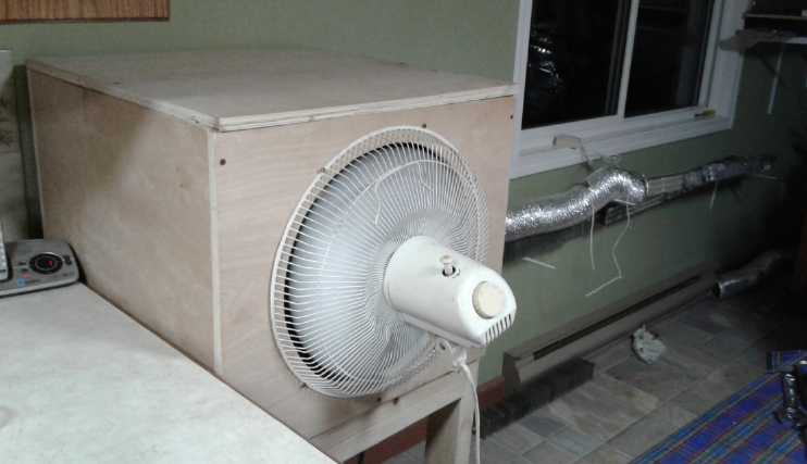 Enclosure with Makita air
compressor (as first
made);
Enclosure with Makita air
compressor (as first
made);
ducts at right loop back to outdoor heat exchanger underneath
compressor box.
It seems there are potentially two main ways to do the
heat pumping.
One is to cludj it with an existing air compressor. This has the
advantage that the heart of the system is ready made. Here one get's
what I've been getting: from COP of perhaps 2 to - maybe, or
seemingly - about 4 or 5, tops, which I seemed to get with the
refrigerator type compressors. But a regular compressor, regardless of
efficiency, expects the compressed air to be used by some other
destination. In heat pumping, the compressed air is simply allowed to
hiss out at the end of the pipes. That is quite a lot of wasted energy.
 The
other and far more effective way would be to make an air compressor
designed
especially for heat pumping. Thanks to some great info sent in by a
couple of readers after my last two newsletters, I discovered how to do
it: after the compressed air has done everything else, given up its
heat to the house and then to heat the incoming cold air in the outdoor
heat exchanger, it can still be used by its decompression to assist the
compressor.
The
other and far more effective way would be to make an air compressor
designed
especially for heat pumping. Thanks to some great info sent in by a
couple of readers after my last two newsletters, I discovered how to do
it: after the compressed air has done everything else, given up its
heat to the house and then to heat the incoming cold air in the outdoor
heat exchanger, it can still be used by its decompression to assist the
compressor.
This ROVAC (Rotary Vehicle Air Conditioner - or it could
as easily heat instead) design from the 1970s uses the cooled,
decompressing air to help compress the incoming air. That gave me the
idea, but my simpler way of doing the same thing would be with two
pistons. The outgoing air would fill the second, in-line cylinder
that has a rod connected to the compression cylinder. When the
same amount of air has filled the outgoing cylinder as is being
compressed in the incoming cylinder, it will have compressed it most of
the way to the desired pressure. This now cold air will have slightly
less volume at the same pressure because colder air is denser, but the
motor is only needed
for (eg) the last 10% and is pumping, and to only 10% additional
pressure over the other cylinder's, rather than all the way up from
atmospheric pressure.
Imagine a COP even of 2 being raised closer to 20 because
so much less additional energy is needed by the compressor. 100 watts
to heat instead of 2000: there's the very cheap building heating!
Better Peltier Modules for Solid
State Heat Pumping?
In January or February I checked on line to see if there
were and better Peltier modules with higher COPs. The Wikipedia article
said some were under development with COP as high as 3. I found some
"high performance" peltier modules
that looked better than most. (A COP of 3 appeared on the graph
lines, but that was with only a 10° temperature differential. The
fridge needed 30° or more.)
Another change from 2012 is all the low cost DC to DC
converters now available on line. One isn't "stuck" with using 12-14
volts from a battery or
putting two modules in series for 6-7 volts. If the best choice looks
like 9.5
volts, that's now a simple screwdriver adjustment.
They were from USA rather than China and hence quite
pricey and pricey to ship. Typically US companies refuse to use the
post office even for the smallest things.
This month I finally ordered four small ones. To my
surprise they arrived on the day a UPS e-mail said they would, instead
of weeks later. (But: 40 $US shipping for 80 $US of parts, and a
further bill for 33$ UPS collect charges (far more than the
tax itself - 6$) came in the mail.) That's certainly how to make your
product uneconomical for the purchaser!
I'd like to say I tried them out, but I threw them inside
the solid state fridge and there they sit. I'm sure I'll get around to
trying them, uh... soon!
Lawn Tractor Electric Conversion
I started looking on youtube for some reasonable way to
break up the grass on part of the mossy turf lawn, in order to turn it
into a garden to try growing grains. Instead I found a conversion of a
lawn tractor to
electric. Then another one. The second one was a guy, Brian Edmund
Electric in Ontario, who had done more than one and who offered a
conversion kit.
Much as I had idly thought of converting mine with my
forklift motor and controller on the cheap, the kit had a 24 volt
motor[, reduction gear for sure] and differential already mounted with
axles for the lawn tractor rear wheels, a one-piece assembly. That
should be quite an efficient drive. And of course all the required
parts for the conversion. That got me. I ordered it (1400$; so much for
"cheap"). In addition it had
two more motors for the two mower blades. No drive belts anywhere.
(Later I
thought the motor/reduction/differential/axles assembly might be
made for some model of mobility scooter. That would have been the place
to find that finished assembly. Oh well!)
The message from all sides was that I wouldn't be ripping
up turf with a lawn tractor. For that I should go up to a garden
tractor - and a 48 volt motor - and "tractor" tread tires instead of
"turf savers", which tend to slip even going up hills. Unless I can
find an old dead one, those cost real money.
But I got the
idea (thinking of "tractor tread tires") that instead of pulling a
plow,
I could weld up steel wheels with protruding (bars or spikes?). The
(side to side) bars
would go down vertically at the front of the wheel as it rolled,
digging in. They would rip up the turf and twist to horizontal as they
came back up behind, scooping up clods of dirt. It should take less
power to drive, or at least, the power (and
tilling depth) would depend on the length of the bars and they could be
made any reasonable length. I could call them "turf ripper" wheels.
The tractor place had thrown out their old
rims. ("Try the dump?" Nope, none to be seen in the vast pile of tires
at the refuse transfer station.) Rats!
Alternate plan... maybe my neighbor with a real tractor
and plow will do it for me?
In Passing
(Miscellaneous topics, editorial comments & opinionated rants)
Catastrophes Galore
(and gardening)
I think I've spoken of all or most of these things before,
other than the "black flamingo" corona virus event.
 Many have been
expecting some sort of
"Black Swan" event, but...
Many have been
expecting some sort of
"Black Swan" event, but...
"No one expects the Black Flamingo!" (...a la Monty
Python)
Now, suddenly, some of the problems anticipated for some
years now are getting real, looming right in front of us.
How bad is the corona virus? Predictably, it is worst in
crowded cities. New York is a prime example. That doesn't mean it isn't
spreading everywhere via air travel, or that one will be entirely safe
even out in the countryside. Much depends on proximity to others and
much depends on careful sanitary measures after being where people are,
or when people come to the door and touch your doorbell, doorhandles,
and so on. Keeping 6 feet distance from others is a big help,
apparently. (It figures that the drug store here is closed and the
groceries are out of sanitation products. Earlier I had asked about
masks but they were already sold out. No one has been the least bit
prepared!) Evidently the almost universal wearing of masks in public
has greatly blunted the spread in Korea. Someone has said that if no
protective measures were being put into place, there would be 40
million deaths. That is almost equivalent to the Spanish Flu of
1918-1919. (50 to 80 million dead, from a global population then under
2 billion) Hopefully it is also wildly exaggerated. This virus, while
wildly contagious, has only a 3-4% mortality rate. (A nephew of mine
who works at a hotel in Victoria had it. Apparently he had one very bad
day with a high fever, but he recovered. I didn't ask, but no doubt he
had very good medical care.)
Many expect this epidemic is likely to abate in warmer
months while people are outside in the
sun, and return for winter 2020-2021. The Spanish flu was also worse in
its
second season.
It has been warned by more than one source that with the
present density of the human population, inevitably some disease will
come along that will kill billions of people. This virus is, then, just
a foreshadow of what's to come. Or perhaps it will mutate and become
more lethal itself. Hopefully that's a decade off, maybe even two, but
we have no
guarantees.
On top of the corona virus two other catastrophes are
looming. One is potential - now seemingly inevitable - famine. This too
has
been warned of for some years. We are so used to having an abundance of
food this seemed - still seems - inconceivable to the majority. But
kicking it off rather suddenly, agricultural production globally was
devastated in 2019. (EG, go over some of the video reports of the past
year
and more on youtube by "Ice Age Farmer". Real figures and articles from
credible sources.) For 2020 we again face outrageous predicted (and
already actual) weather, widespread shortages of seed of many types
owing to drops that didn't grow last year, and even shortages of farm
equipment and repair parts owing to the virus related shutdowns, plus
farmers everywhere who are now bankrupt after last year, and so many
farms won't be
planted this year regardless. And each foolish edict from governments
seems exactly calculated to make a bad matter worse. (I'm sure it's not
deliberate, but no kidding: for example even many retail and mail
order garden seed outlets stopped taking orders in March or they are
out of product. Then at the start of April, some US state governments
had also banned sale of "non-essential" items... which included garden
seeds already sitting on store shelves! As scarcities begin to
manifest, food, seeds and the spring planting season are going to
waste. Milk is being poured down the drain at dairy farms owing to
shortage of labor at the dairy plants and in the UK eggs are rotting
simply because of an egg carton shortage. All while purchase quantities
are being limited in the groceries.)
People wanting to get a little ahead on food for whatever
emergencies are now being called "hoarders", and they are being blamed
along with the virus, but if the warehouses weren't getting empty
already the supply lines could handle these things.
The other catastrophe (along with economic collapse) is
financial
collapse. In Y2K, US dollar base currency was something like 850
billion dollars total. Now the US central bank is nonchalantly printing
6 TRILLION dollars almost overnight to prevent collapse? That's over
18,000 $ for every
American man, woman and child, on top of all its other egregious money
printing. Bank of Canada is now also going to purchase assets - in
accord with all the other central banks. As the central banks print
enough money to buy every investable asset, everywhere, from everybody,
and the
price of food keeps going up, how long will confidence in the currency
remain? And how do banks make money with negative interest rates?
And now that I've hit 65 and have received just two
fabulous monthly pension deposits of 1200 $, the Canadian government is
going to give lots of people all over of any age (excluding the
retired) over 2000 $/month "pensions" owing to the virus.
Unless some very different directions are suddenly chosen,
the banks are
going to collapse and the money will hyperinflate and become worthless.
In what order those happen or with what speed I won't try to guess.
But even these may not be all the troubles that we
experience in the coming seasons. Volcanic activity and earthquakes
have seen a steep increase in recent years. Some places are already
suffering from such activities. If a huge volcano like Yellowstone were
to go off in a major eruption, anywhere 100 miles around it could be a
death zone, and with the ash clouds it could disrupt life in much of
the continental USA and probably not leave Canada untouched.
And recent measurements of the ocean water temperatures
and undercutting of ice sheets in Antarctica and Greenland are warning
us that 3 meters or more of sea level rise may come much more rapidly
than any past predictions.
And if the ice is thinned substantially over Antarctica
and
Greenland, they are sure to rise up in compensation as the immense
weight of
the ice is reduced. When they do, other areas will have to subside. So
probably some continental lands and coastlines will sink by still more
than the 3
meters of actual ocean rise. Along with storm surges and tsunamis,
hundreds of millions could be displaced and become internal or migrant
refugees. Maps or satellite images of the world are likely to look
visibly different by the middle of the century.
Through all these causes, the population will be much
reduced - to under three billion, perhaps even under two. In the middle
of what looks like unmitigated
disaster, the silver lining is that if and as much of the façade
of today's
civilization is ripped away, it is only in order that it be replaced
with something much better - a world and society more humane and
equitable, without wars, with a higher quality of life and plenty for
everyone, stable and
sustainable. In order to renovate, some of the old and inferior aspects
of the dwelling must be torn down in advance to make room for the new
and superior construction to come.
Addendum: Here's another aspect to the farm production crisis
that has "cropped up". Plants need phosphate, the "P" of the three main
"N-P-K" fertilizers. It is mined, and it's getting harder to extract.
(What about that is sustainable in the first place?) Last year with the
bad growing season, demand from US farmers was down, and so costly
phosphate mining operations shut down. Now there isn't enough available
in the USA for this year. China, a very large producer, has banned
exports owing to their own needs. It has been said that US farm yields
could be down as much as 50% from low phosphate levels in the soil
alone. (And they banned phosphates in laundry detergents because the
fertilization effect caused algal blooms in a very few streams or
rivers!)
And to bring that down to the practical level:
* I call nitrogen, the "N" of the above main fertilizers, "vitamin P
for plants". Actually that's spelled "Pee". While I wouldn't add it to
growing garden plants, it's the easy and free way to fortify garden
soil in the winter and when and where there's nothing planted.
* Here on the BC north coast where it's deficient in soils, lime
(calcium compounds) can be added as broken or crushed seashells.
* Potassium ("potash" - the "K") compounds can come from wood ashes.
* Other than buying "bone meal" (pricey) I don't know where to get
phosphates.
* Seaweed is a great fertilizer. (Maybe it has phosphates?)
Fertilizers aside, if it would just warm up above near
freezing with frost at night and occasional snow flakes in the cold
rain (this is April?), I could put some of my seedlings out in the
garden. Now I'm wondering if I should concentrate on greens in the
house. Here's some of my indoor gardening work.
 Some seedlings. They have become
"leggy" - tall
and scrawny - owing to
Some seedlings. They have become
"leggy" - tall
and scrawny - owing to
insufficient light before I finished the "LED wall garden".
 Here are some quinoa seedlings
where the lack
of light earlier really shows.
Here are some quinoa seedlings
where the lack
of light earlier really shows.
(The onion bulbs quickly became rootbound and had to be planted in
the greenhouse. They didn't died of exposure and are growing. Yay!)
The coffee bushes lost a lot of lower leaves owing to having light
coming
only from straight above.
 Some readers will remember my old
"LED garden":
a table with
Some readers will remember my old
"LED garden":
a table with
lights underneath (here turned off) and some rolling dollies for
planters.
I started trying to put some shelves on the wall in the corner, with
some real "grow light" panels. It wasn't as wide to the window as
I had been visualizing - not enough room for two columns of shelves.
(Under window are heat pumping radiator pipes.)
 I ended up taking the legs off
the 'light
table' and mounting it up high on the wall.
I ended up taking the legs off
the 'light
table' and mounting it up high on the wall.
I can't help but think the 20 LED "light bulbs" (~170 watts) look like
a lot more
light than the three grow lights beneath (84 watts).
 The setup by the start of April.
The kitchen/dining area is pretty cold if it's cold out,
so the curtains help keep heat from the lights in.
(They meet quite nicely, but the left end has a gap
caused by the "U" end of the heat pump pipes. But it's a
couple of degrees warmer inside when the lights are on.)
The cherry tomato on the left in the square pot, left over
from last spring, pollinated with a brush, and draping over
the spinach box on the table, is producing enough for salads.
 Here it is open to view with the
curtains open
and the lights out.
Here it is open to view with the
curtains open
and the lights out.
There are now three levels of lights with plants under them.
(More light panels are to be added under the middle shelf.)
Curing
Eye
Floaters with Pineapple?: Bromeliads, Bromelain
Youtube suggested a video by a doctor whose videos I'd
seen before. He was commending a recent study where people ate
pineapple, and their eye floaters disappeared. It wasn't a large enough
sample size to wake up the AMA, but the success ratio, near 100%,
sounded very convincing.
Pineapples are a member of the recently evolved (12 MYA) bromeliad
plant family from South America. It seems the active ingredient in
pineapple is bromelain, which can be extracted from the stems.
I looked that up, and it seems bromelain can dissolve proteins. What
are eye floaters? Dead proteins ("and other debris" - Wikipedia) inside
the vitreous humor in the eyes. So this seems to make sense.
Not being much of a fan of eating pineapple (and
invariably getting cold sores in my mouth), I ordered some bromelain
capsules. (Actually they were "turmeric and bromelain" capsules from
CanadianVitaminStore.ca in Victoria just before they stopped taking
orders owing to unprecedented demand. ...And I thought that was just
garden seed companies!) I'm taking one every day. I (very much) hope to
be able to report good results in 2 or 3 months.
Small Thots
* People always matter more than things. If costly jet liners have to
sit on the ground to slow the spread of the virus, that is better than
having to raise and train new flight crews, and also to replace all the
talent and experience of the passengers who will die.
* OTOH with food already in short supply, the world can't afford
another bad harvest season. If farm labor isn't out there to plant in a
timely manner this spring, as it appears various factors are causing,
the harvests could be even worse than last year.
So, people are at risk in more
ways than one. Where is the "best compromise" line to be drawn?
* US Government: We're closing the border to Mexican migrant workers
because of the corona virus.
US Farmers: We need our trained, willing and able labor force! If we
don't have farm labor, we won't be able to plant, and Americans won't
eat next winter.
(US Government reaction?: Farmers are threatening us again! -- Actually
I think in a brief fit of realism they lifted the
ban. But if the workers have to undergo 14 days quarantine they may be
available pretty late - and will they even come?)
* How might corona virus rate in causes of death in the overall scheme
of things? Respiratory diseases and infections were third and fourth in
2017. Hopefully at worst the virus just might double that, reaching 5
million or
more, or it might be under a million. (300,000 people drown
every year?!?)

* Another addendum to the hair care bits
of recent months: There is a slight feeling of soreness, tenderness,
discomfort (I can't find the right word) of the scalp which I have come
to associate with scalp conditions
improving after having been poor, rather than with it getting worse. I
like to think it happens because previously dormant or damaged hair
follicles are coming back to life. I had
my hair cut very short, almost shaved (she called it "shaved") because
I
had heard it can help with hair loss (the one thing I hadn't tried in
recent years), and also to better see what hair loss I had.
I found the whole top, at the middle, from almost the
front to the back seemed thinner. (the top-back is where I had
previously noticed it in double mirrors.) With 3/4 inch at the front
being just fine, and with my hair
normally combed sideways, I might never have noticed the rest until it
was virtually bald. Without treating it, I might have been headed for
the "Telly Savalas"(sp?) look. After that, I noticed that "discomfort"
of
the scalp at times in that area. So I'm not holding my breath, but I'm
hoping it will come back to
full thickness eventually. After a month or so, it finally occurred to
me to take a couple of pictures. It's less obvious but still visible.
So if it does get noticeably thicker, I'll have "before" as well as
"after" pictures to show it. (Ug! The photos showed more thinner areas
on top than I had been aware of. They looked worse in the straight-on
images than in the mirrors.)
ESD
(Eccentric Silliness Department)
* There is not much silly this month. Swallowed overdose of "serious"
and "viral hysteria". (I thought of two good puns at some points, but I
didn't get them written down... gone. I'm sure they must have been
fantastic!)
* In a video about grid tied plus battery solar in Australia (or was it
New Zealand?) a screen flashed up "5¢ earnt". I laughed for a
moment at this weird spelling. But if money is "spent" why isn't it
"earnt"? Apparently it is in Australia. And why do we use "ed" for all
"regular" past tense verbs anyway? The "e" is often silent. Why is it
(eg) "relayed" and not "relayd"? (Not to be confused in either case
with "relaid".)
* The kitchen table was stacked with debris, largely from 3 months
worth of heat pumping builds and experiments. They being mostly
finished, one day I resolved to clear it off. I didn't get far. I would
take something out to the workshop or the greenhouse and get
sidetracked there on something else. Finally I decided to set myself a
more realistic goal: I cleared off a small but somewhat cluttered end
table in the livingroom instead.
(I did eventually finish clearing the kitchen table, some days later,
bit by bit.)
"in depth reports" for
each project are below. I hope they may be useful to anyone who wants
to get into a similar project, to glean ideas for how something
might be done, as well as things that might have been tried, or just
thought
of and not tried... and even of how not to do something - why
it didn't
work or proved impractical. Sometimes they set out inventive thoughts
almost as they occur - and are the actual organization and elaboration
in writing of those thoughts. They are thus partly a diary and are not
extensively proof-read for literary perfection, consistency,
completeness and elimination of duplications before
publication. I hope they add to the body of wisdom for other
researchers and developers to help them find more productive paths and
avoid potential pitfalls and dead ends.
Electric Transport
Lawn Tractor "Rototiller"?
I ordered a kit to turn my lawn tractor electric. 24
volts. Charge with solar panels and run it for free. Regardless, I want
to use it to turn some lawn into a garden plot.
But the message from all sides was that I wouldn't be
ripping
up turf with a silly little lawn tractor. For that I needed to go up to
a garden tractor - and if it was electric it needed a 48 volt motor -
and
"tractor" tread tires instead of "turf savers", which on the lawn
tractor tend to slip even
just going up hills.
But when I wrote the above line, it struck me: ...want to
rip up
turf ..."turf saver" tires. What's wrong with that picture? Then I
thought, in fact, maybe that's the key: instead
of just "tractor" tread tires and making an attachment to plow or till,
I could make a welded steel
rear wheel (or two?) with spikes/special blades or something to
plow/till/harrow the turf simply by driving over it. Maybe something
like diagonal "tractor tread" pieces but hard steel, longer sharp thin
"treads", angled toward the rear. They would dig down almost vertically
into the dirt, then as the tire continued to turn, the "blade" would
twist to almost horizontal at the back as it lifted out of the dirt.
That should really rip up the moss and ground simply by driving over
it. (If you drove fast clods might even be flying into the air behind!)
I would change the
regular tire(s) for the special wheel(s) after driving out to the
intended
plot. The
wheel(s) sure wouldn't slip while plowing when the plow is the wheel!
And they wouldn't tax the motor like dragging a plow. Gosh, I may have
something here!
The rims of the tires are much
smaller than the tire outer diameter. Some old regular rims that
already fit the tractor might be perfect. Instead of tires I could
attach the
ground ripping components to them.
I found a catch: the tractor place had thrown out all
their old rims. "Try the dump." I suppose I could do that. (Nope,
couldn't find any there.)
Hmm... OTOH... I found a youtube video where someone had
sprayed his overgrown gravel driveway with salt water to kill the
grass. Maybe that would be an easier way than mechanically ripping up
the dirt: just spray salt water and kill the grass, moss and weeds a
few times to prepare the soil for planting? Hopefully by the time one
was planting the old stuff would be pretty dead and a new lawn wouldn't
quickly overwhelm all attempts to weed the garden.
Other
"Green"
Electric
Equipment
Projects
Simple
Air
Compression
Heat
Pumping
- or -
How to Heat a Building Almost for Free
The fridge compressor was pretty quiet and I couldn't hear
it with the warm air "computer" fan running on the heat pump radiator
duct. I had put a 15 ohm, 5 watt resistor in series to slow it down,
but it only slowed it a bit. The fan wasn't loud but it was continuous
with an "edge" to it, and it was so cold out I left it running to help
heat whenever I was home to monitor it. By the 8th I noticed that my
tinnitus had gone wild. I was listening to a piercing tone in my ears
at all times, especially when it was quiet. A much quieter fan
arrangement was needed.
I didn't dare run the system when I wasn't there.
On one evening I had caught the air pressure rising and I turned it
off, and on another I noticed the compressor sounded labored. It had
pinned the needle on the air pressure meter. (and in fact bent it. I
had to get a new one.) It must have been well over 250 PSI - maybe 300.
A pipe-clamped plastic-on-copper join was hissing air, which is
probably the only reason
it didn't go even higher. Air compressors compress humidity along with
air, and when it reaches the outside exit, decompresses and cools
perhaps below outdoor temperature, it condenses and the water was
apparently freezing and plugging up the outlet. I opened the tap later
and a tablespoon or more of water came out.
Ideally one would have a little pipe heater at the exit,
perhaps activated by excess pressure, to prevent freezing. Failing
that, something to shut the system off if the air pressure was too
high. Nobody in town had an air pressure switch. I ordered one from
China (3$) which... hopefully... should arrive by summer.
I rather dreaded hooking up the loud Makita compressor. I
had, or did have, a larger fan that was probably quieter, but I
couldn't find it. One advantage however is that the Makita has its own
shutoff at 120 PSI, and so can safely be left to run unattended. I
could leave it running when I went out. And it had more power. I could
close the kitchen door to block the noise and the kitchen would get
warmer instead of colder. It would (surely!) even want a thermostat
which would shut it off part of the time.
(8th) I cut the pieces of plywood to make the compressor enclosure, and
screwed the bottom and three sides together. The last side needed
cutouts for the warm air duct and the fan and the top would go on after
that.
(10th) Where was that fan? I thought I had seen it, but perhaps I thew
it out when I moved? Not finding it anywhere, I went to
Skidegate. Co-op didn't have one (no surprise), Fields didn't have one
("wrong season") but said I could go to Fields.ca and order one, to be
shipped to the store. I picked one out and got to the "checkout", where
I discovered there were shipping charges ("under 50$"). I looked again
at the choices... "oscillating pedestal fan". Maybe that would be
quieter?...
Wait! I already had an "oscillating pedestal fan"! Someone
had given it to
me a few years ago. The pedestal had broken, and the front of the fan
cage had fallen off. But somehow it hadn't got thrown out in my move.
Wasn't it sitting somewhere in the corner of the shop? Sure enough! I
guess I just couldn't see a white fan in 1/2 a cage in the clutter when
I was looking for an open black fan. So I already had one, and plugging
it in and on "low", it proved to be as quiet as a fan is going to get.
I cut a big round hole in the box and mounted it by putting screws on
the outside of the cage rim.
The motor was too fat to mount inside to blow outward, so
once again it blows into the box and from there into the duct rather
than sucking through the duct and blowing outward. Having determined
that all the pipes (and hence the duct) should gradually slope down to
expel moisture, I'm pretty sure that's backward, trying to push warm
air downward instead of pulling it upward. Maybe later I'll figure out
a mounting so it can work the other way around.
 (11th) Much of
the day was occupied with making a stand for the
compressor box. (It takes longer when you're planing your own lumber
that you milled.) Like the last arrangement (with the fridge compressor
on a chair) I wanted the compressor highest up with the pipes gently
sloping down all the way so moisture would flow along them and go out
the outdoor end. Otherwise quite a lot builds up and burbles in the
pipe. I put the box on the stand and
then lifted the compressor into it.
(11th) Much of
the day was occupied with making a stand for the
compressor box. (It takes longer when you're planing your own lumber
that you milled.) Like the last arrangement (with the fridge compressor
on a chair) I wanted the compressor highest up with the pipes gently
sloping down all the way so moisture would flow along them and go out
the outdoor end. Otherwise quite a lot builds up and burbles in the
pipe. I put the box on the stand and
then lifted the compressor into it.
Then I laid out my finned pipes and found fittings to
connect them all together, and did some required soldering. There were
too many to simply have a straight line, and anyway I wanted some of
the wall space for a new LED indoor garden setup with adjustable
shelves. So the compressor is at the same end as the outdoor heat
exchanger and the pipes do a U-turn and are double along the wall.
The elbow I wanted to use didn't fit properly into the
"drain" hole in the compressor. It only went in 1/2 a turn and ended up
pointing the exact opposite to the desired direction. I got
a "1/4 inch NPT threading die" and expanded the hole in the compressor
a bit.
(12th) I uncovered a way to make a far higher performance compressor,
by making it with a decompressor to help drive the compression cycle.
Efficient
air heat pumping is possible after all! A COP of 10 started looking
minimal. It might not attain to 100, but that's the direction it's
headed I've written that up down below. But it was still frosting and
snowing and under 5°C this far into March. To have heat in the
meantime before I ran right out of firewood, I still had to get the
Makita compressor connected and pumping heat, even if it was only COP 4
or 5.
One thing I wanted was to
make the 180 degree bend at the
far end as a smooth curve without any sharp corners where the air would
make a hissing sound, as I heard in the first couple of experiments
with a 90 degree pipe bend. From the sound I had suspected a leak at
the elbow.
I wished I had some gallium. I've heard of that from brass
musical instrument makers: heat up the gallium in warm water, pour it
into the tube of the instrument, then dip it in cold water. The gallium
freezes, making the tube into a solid rod which will bend nicely. Then
dip it in warm water again and pour the gallium back into its bottle.
 I
hoped the building supply would have a pipe bender. They
didn't, but someone suggested a place that did. I went there and a guy
grinding a piece of metal said he didn't think theirs would work for it
- it
would probably kink. He said to fill the pipe with water, put it in
the freezer, and with frozen ice in it, bend it around something the
diameter I wanted.
I
hoped the building supply would have a pipe bender. They
didn't, but someone suggested a place that did. I went there and a guy
grinding a piece of metal said he didn't think theirs would work for it
- it
would probably kink. He said to fill the pipe with water, put it in
the freezer, and with frozen ice in it, bend it around something the
diameter I wanted.
Brilliant! Exactly what I needed! Why did I have to
think "gallium", expensive and hard to get, when there was water and
ice? Perhaps the instrument makers are afraid of freezing water
splitting the pipes - or just that ice expanding them a bit might
change the
tuning and gallium doesn't expand when it freezes? I cut a block of
wood to
the right shape and drilled a hole in it for one end of the pipe. I
clamped it to a workbench. After I waited long enough and the ice was
solid (2nd try - and the unpressurized ice didn't split the short
pipe), I took the pipe out to the workshop and bent it around
the wood. It worked beautifully! The quite steeply bent soft (annealed)
copper pipe wasn't flattened at all, and had had no tendency to kink.
(Now I know how to make brass instruments... or maybe a shower pipe
more to my liking for the bath, aimed down a little steeper!)
 The "U-turn" pipe at the middle
of the radiator
pipes.
The "U-turn" pipe at the middle
of the radiator
pipes.
I used a threaded pipe union on one end so the two
lengths could be handled separately until assembled.
(Egads, the plant grow lights really make the colors weird!)
Hooked up and running.
 With the fan that draws instead
of pushing.
With the fan that draws instead
of pushing.
(18th) I finished putting it together, and I tried it out 2 or 3
times. The compressor uses so much power it makes the plant lights
(probably on the same circuit) flicker a bit.
Before the last test I
found a different fan at the refuse transfer station. The blades and
rotation were set to draw air through the motor instead of pushing it
away, so I cut a new piece of plywood (as it was smaller than the other
one) and put it on to blow the air outward instead of inward. (It seems
to blow it out the sides more like a centrifugal fan. Perhaps it can't
get enough air through the duct - one can really feel the air sucking
into the end of the duct.) The results seem puzzling. When it's turned
on, the room temperature seems to rise quickly. That seems really
exciting. Then the rise slows dramatically. After an hour it's gone up
maybe 2 or 2.5°.
It uses around 900 watts (the fan accounting for 65). When
I put in 920 watts of electric heaters, the temperature only rose
somewhere over one degree in an hour. So it would seem the COP is at
least better than 1. But it seems more like 2 than 4 or 5.
(22nd) Similar results. It rose a full degree in 8 minutes, then slowed
down and hit 2.5° in an hour. There are any number of wild
variables:
- outdoor temperature
- temperature of the livingroom: if the livingroom is colder than
the kitchen it definitely heats slower.
- The fridge: when the fridge runs, the room temperature goes up
in a few minutes by about 1/2 a degree. (Amazing!)
- door openings and closings (livingroom door, door to cold
entryway, patio door to outside).
- wind chill.
- sunlight coming through the patio doors
- Whether or not the plant lights are turned on.
(270(?) watts of extra heat)
- trying out different air pressures
- The heat pumping blows air, while the electric radiant
heat doesn't. So the heat pump air was probably more heating all the
walls and furniture. The temperature gain might last longer than from
the radiant heaters. Or not - heating the windows is a losing
proposition.
 I
thought about the air flow. I opened the top of the box
and set it slightly askew so it could pull some air through the box as
well as through he duct. Sure enough, the air started blowing out
forward from the fan instead of coming out sideways around the edges.
It must have greatly increased the flow. The compressor heat - both
from its power consumption and from compressing air - must have been
building up in the box instead of blowing into the room.
I
thought about the air flow. I opened the top of the box
and set it slightly askew so it could pull some air through the box as
well as through he duct. Sure enough, the air started blowing out
forward from the fan instead of coming out sideways around the edges.
It must have greatly increased the flow. The compressor heat - both
from its power consumption and from compressing air - must have been
building up in the box instead of blowing into the room.
With the change, the room temperature started rising
rapidly, degree after degree. It soon seemed to be up from 18.2° to
21.0° - notably warmer than the livingroom where I had fallen off
on tending the woodstove and there wasn't much fire. That seemed really
exciting until I realized that the fan was now blowing the warm air
across the room onto the temperature sensor 6 feet away. So that was
really the "warm air out" temperature. That was probably the same
reason as for initially getting better results than later in previous
tests, too. Still, it was blowing a large volume of warm air and could
hardly fail to be raising the room temperature. I opened the crack a
little wider and the air blew even more straight out.
The finned radiator pipes beyond the air duct actually
felt like they were probably above room temperature, too; not really
warm, but not cold either. But the far end was cooler than coming out
of the compressor, so it was radiating.
After the time spent writing this, the air coming across
the room was 22.1° instead of 21.2. That would be because the whole
room was actually warmer by that amount. I turned the noisy thing off.
After a few minutes the temperature read 19.8°. Still, it had
started off at 18.2.
In the evening I ran it again, this time with the
thermometer aside from the warm air stream. Outdoors it was +3°.
Room temperature went up by 1.2° in 45 minutes (from 17.8 to 19.0).
Then I turned it off and put on the 920 watts of electric plug-in
heaters. In 45 minutes they raised the temperature a further .5° to
19.5°. Does that make the COP 1.2 / .5 = 2.4? probably something
like that. That's disappointing, but perhaps some parts of the
compressor are still getting too hot?
 It would seem
that the next thing might be to make some
strategic holes in the box - maybe even put short ducts or shrouds
inside - so that the air flow would be directed right across the
compressor elements making and having the heat. A coefficient of
performance of 4 to 5 or more from a regular air compressor just might
be in there!
It would seem
that the next thing might be to make some
strategic holes in the box - maybe even put short ducts or shrouds
inside - so that the air flow would be directed right across the
compressor elements making and having the heat. A coefficient of
performance of 4 to 5 or more from a regular air compressor just might
be in there!
On the 23rd the house was cold and I decided to run it
while I took a bath. I had taken the lid off. This time I put it back
on with a bigger gap at the back. And I realized that was the right
place:
the fan had to draw the air through the box from the back. If I also
put in a baffle or two, it would have to draw it right past the
compressor. The blow from the fan was stronger with the larger gap and
I realized I hadn't had it open wide enough previously.
I checked the initial temperature: 16.7°. After I came
out of the bath I turned off the racket, and checked again: 15.5°!
Well, it might not be super, but it couldn't be cooling instead of
heating! What was that I said about too many variables? The sliding
door was open to the cooler entryway/alcove area. I guess the fan
blowing so much air had caused more cold air to blow in faster from
there. (Okay, that particular variable should have been under my
control. But I didn't notice.) In fact, that door being open was
probably why the house was cooler in the first place. I closed it, and
soon the kitchen was reading 16.6° again.
(24th) I made the air baffles and tried it out during the day, for an
hour. The room went from 17.8° to 20.1, a 2.3° rise. Of course,
it was +7° outside and some sun was breaking through the patio
doors. Then again, the fire was out in the livingroom so it was cooler
than the kitchen. Variables!
Soon after I turned it off, I opened the lid and felt the
components. The compressor heat sink fins and its ouplet pipe's fins
were too hot to rest one's fingers on. Clearly the COP would be much
better if those could be kept cool. That meant finding some way to get
air blowing right across them at a good speed. Since they were inside a
box and under a shroud aimed sideways, that was going to be tricky. On
the 26th I fussed around and cut some pieces. I arranged them so they
would try to push air through the shroud the same way as the motor's
fan. That should be a fair reinforcement.
Outside it was +7° C. The room went from 17.8 quickly
to 17.6. Grr! Then it started to rise, and in an hour it hit 19.3°.
I was disappointed. But it felt warmer to me. Then I realized that in
spite of all the moving air, the dining area on one side seemed warmed
than the kitchen area where the temperature sensor was. I moved it and
soon it was reading 19.8°! Since I don't think the temperature - in
this single "two cubes" space - was stratified before, that was
2.0° degrees warmer than it had been - except the kitchen was only
up 1.5°. I moved it in front of the fan, five feet away, and it
soon read 22° - the warm air out, even at that distance, across the
table. I shut it off and opened the lid. The compressor fins still felt
hot, but I don't think they were as hot as before the baffles. That
might be about the best that can be done without going to great
lengths. If I'm going to go to great lengths, I might as well do so
making a heat pumping air compressor that would really perform and give
far better performance - very high COP.
I then turned on the baseboard heaters that I almost never
use. (8:47 PM) I had checked the ratings: 1250, 500 and 500: 2250 watts
total. In 1/2 an hour temperature went from 19.8 to 21.8; 21.9 or 22.0
on the dining side where the heaters were. That would have been 4°
in an hour, where the heat pump had got about 2°. So perhaps it was
heating around 1125 watts, and using about 900. 1125/900 = 1.25
COP. That was pretty disappointing - and it certainly didn't seem
as good as I had been getting from the fridge compressors. Still, with
the heat I could feel in the cast alloy fins after it was running it
was obvious it wasn't working as well as it ought to be. The cast
cylinder and fins probably didn't even transmit the heat very well, so
the cylinder and piston were running even hotter than anything that
could be felt on the outside, instead of cool.
A compressor made for the job would give far better
results. The potential to change the whole outlook for heating in the
north (and doubtless air conditioning in hot climes) is still epic and
untapped.
 I noted
previously that while an electric air compressor seems to use an
amazing amount of power even to blow uncompressed air, a bicycle hand
pump takes virtually no effort until it is actually compressing. I
found one in the garage, so here it is for anyone who hasn't seen how
simple they are. The tapered rubber piston seal presses against the
cylinder wall on the power stroke, but lets air pass on the back stroke.
I noted
previously that while an electric air compressor seems to use an
amazing amount of power even to blow uncompressed air, a bicycle hand
pump takes virtually no effort until it is actually compressing. I
found one in the garage, so here it is for anyone who hasn't seen how
simple they are. The tapered rubber piston seal presses against the
cylinder wall on the power stroke, but lets air pass on the back stroke.
April 4th - Another Test
As I still haven't got this newsletter out... on chilly
April 4th morning I thought to try out the Makita system again, this
time with the large fan again, now that I had made the slot and baffles
in the compressor housing. It looked the same as originally except that
I opened the slot in the lid still wider. And it had the baffles
inside. It seemed to work better.
 An improvement to the testing was that the previous day the digital
thermometers I had ordered had arrived. As one might expect, they
didn't seem to entirely agree with each other to .1°, but 3 out of
the 5 were within .2°. The others were "add .3" and "subtract .2" -
at room temperature. Things changed somewhat outdoors at around
+2°. They all read about 1° higher than the old one, so it's
probably the old one that's off. They took those horrible little button
cells instead of (rechargeable) "AA" or "AAA" cells. Those will become
an annoyance. Maybe I'll still look for some others and pay attention
to what batteries they take?
An improvement to the testing was that the previous day the digital
thermometers I had ordered had arrived. As one might expect, they
didn't seem to entirely agree with each other to .1°, but 3 out of
the 5 were within .2°. The others were "add .3" and "subtract .2" -
at room temperature. Things changed somewhat outdoors at around
+2°. They all read about 1° higher than the old one, so it's
probably the old one that's off. They took those horrible little button
cells instead of (rechargeable) "AA" or "AAA" cells. Those will become
an annoyance. Maybe I'll still look for some others and pay attention
to what batteries they take?
After some use, it seemed the amount of disagreement
between units wasn't constant. Perhaps the readings vary a bit
depending on the state of the batteries, among other things?
I started about 11 AM PDT
(9:12 AM actual local time). Outside was +3°. The kitchen was
14.9°. Once it had been running for a bit, the warm air out the
rear slot was 7° warmer than that going in: eg, 22.8° versus
15.8°. As well as saying the 900 watts was making more heat than
the 150 watts of the fridge, that higher rise cuts in half the
potential COP compared to 3° rise from the small fridge
compressors. In addition, the air coming out at the left of the rear
slot was much warmer than that from the right (around 4° warmer
than the incoming), which suggests that the airflow inside the box is
still less than even or optimum. Perhaps I should examine the baffles
carefully. Either that or... have an even bigger, faster fan? Or
another fan inside the box, blowing right on the compressor? In half an
hour the room (and intake air) was up to 16.6° or so. It didn't
seem like much performance.
I discovered that the farther into the housing I put the
sensor (even being sure it wasn't touching or right next to the
compressor), the warmer it was, until it was as high as about 9°
above the incoming air. Yes, definitely the circulation was not the
best in there, and that's partly what was killing the COP. Maximum
potential COP with 10° rise is only 30, where with 3° it's 100.
And the poor efficiency of a regular air compressor of course brought
either of those figures way, way down, but more so with 10°.
I felt the radiator pipe where it came out of the duct
(which was much shorter than the pipe - another inefficiency) and near
the end where it went out the wall into the outdoor heat exchanger. It
definitely got cooler as it went, so it was radiating some small amount
of heat. But it seemed trivial compared to the warm air blowing from
the enclosure.
In an hour the room was up to 17.1°. The kitchen area
wasn't as warm, 16.5°. In spite of an open passage and being open
between the countertop and the upper cupboards (at eye level to the
ceiling), it was taking a while to catch up to the dining area. After
about an hour and a half I turned it off. The room hadn't quite hit
18°.
In about 20 minutes the room had already dropped to
16.6°. At 12:36 I turned on the two portable radiant heaters
totaling 920 watts. In half an hour it was up again to 17.1°. Soon
after that it was 17.5° -- because the fridge had come on. It shut
off again having added .4°. The fridge (itself a heat pump) is a
wild card. Had it been on with the Makita heat pump? Probably, but in
the noise there was no way to hear if it was running. And the plant
grow lights had been on part of the time with the heat pump, but I had
turned them off to take a picture. When was that? I put them back on
for the last 15 minutes of the one hour radiant heating test. Also, I
had put a fire on in the livingroom (long common wall) and it was
substantially warmer, and it had gone up to 4° outside, so the
kitchen should be easier to heat. The the end of an hour, the kitchen
was 17.7°, up 1.1°.
Hmm... about 2.2° rise in an hour with the heat pump,
compared to 1.1° for the radiant heaters of very similar power that
should have had a slightly easier time heating the kitchen. That made
it better than I had thought - maybe 2.5 COP or at least over 2. It
wasn't a stupendous unit that would make the room comfortable in a
short time using just 950 watts of power. And it was very noisy.
Perhaps it's practical except for the noise, but if I want to heat the
house, the workshop, and maybe the garages and the greenhouse as
needed, all very cheaply, then creating air compressors made for heat
pumping is really the key.
Designing a High Performance Heat Pump Air Compressor/Decompressor
(11th) Could there be better ways to make an air compressor
specifically for heat pumping? A couple of readers sent me some little
known or obscure
information on compressed air systems. (Wow, thanks!) Apparently way
back, even before
1900, people were experimenting with complex air compression and
decompression systems. And there was at least one gem, and probably
some more that I didn't get as far as reading and comprehending.
In 1926 someone apparently made a car that needed gasoline
to get up
to 10 MPH, but above that it used a complex system to propel the car on
air alone, and it could get up over 60 MPH - a very high speed at the
time.
It was explained that this wasn't perpetual motion, it was
actually solar energy propelling the car. Acoustics were involved: a
complex mechanism put more air into the pressure tank when the sound
wave created a low pressure point. I didn't follow all of this document
which was
whole chapters out of a book, but I suppose - assuming it actually
worked (I'm not 100% convinced as the inventor didn't disclose all the
details) - that the air came out the end
cooler than ambient after going through three compressed air tanks and
various heating, cooling, compression and decompression cylinders in
the engine, so it was the ambient temperature and pressure of the air
that was being used to drive the car. Wow! (I wonder what happened to
him? Instead of becoming rich and famous, people who have invented such
things usually seem to have disappeared from view soon afterward with
no further news.)
Apparently Nicola Tesla was quite involved in the
technology around 1900. There were compressed air railway locomotives.
I expect they had to start with a charge of compressed air, but by
going through different stages of expansion, compression, heating and
cooling, with three tanks at changing pressures and temperatures,
evidently they got a lot more out of a tank than (eg) Tata Motors
compressed air powered vans in India do today.
Anyway, that info was a couple of chapters from a book.
I'll get around to reading it carefully sometime. Soon!
Another
reader sent a document describing "ROVAC", ROtary
Vehicle Air Conditioner from the 1970s. Since it had a heat radiator
(here outside the cab),
it could have been used either for heating or cooling. Of most interest
was the heart of the beast, the rotary compressor itself. It looked
like it would be pretty quiet. In one half, the air was compressed
(and sent to the pressurized radiator). In the other half of the
rotation that air (after cooling in the radiator) was decompressed
again (making it
even cooler than ambient, for the air conditioning).
I thought that the design seemed needlessly complex and
lossy by friction. Air can be decompressed just by letting it out
through a valve.
Why waste half the rotary compressor mechanism to do it? Was it just to
decompress it gradually and hence quietly?
I looked at it
again in the evening (still 11th) and suddenly realized it had a huge
advantage: The decompressing air helped power the compression! If air
compression was akin to trying to lift up a heavy elevator in a shaft,
the
decompression was a counterweight dropping down on the other side,
balancing it all out. The whole system would use far less energy.
It failed to become commercial. One suspects the
compressor was just too complex mechanically to really work well. It
must have had a lot of friction with all its moving, sliding vanes
having to seal on all sides in the elliptical cylinder. And no one
thought of it potentially for building heating, owing to it being
intended "for vehicles" and "for air conditioning". On a petroleum
vehicle there's no use for heating because most of the energy from the
fuel becomes waste heat anyway, readily available to heat the cab.
Someone on a discussion list had mentioned using
decompressing air to power a turbine to recover compressor energy. This
did it all in one unit! It compressed air, which takes energy, but it
would more freely turn because it was equally decompressing it and
returning much of that energy on the way out. The main work of
compression was
done by the decompression.
There is a loss in the air
itself. Heat pumping isn't magically free. The
pressure is equalized throughout the radiator section, but cold air is
more dense than warm air at the same pressure*. To maintain pressure,
no more molecules of
air can be decompressed than were compressed, so the volume or air to
be decompressed must be less than that being compressed. How much less?
If the air temperature goes from 300°K (when compressed) to
275° (27°C to 2°) through the radiator and outdoor heat
exchanger pipes on a cold day, I expect the cooled air should be
275/300=92% of the volume of the room air at the same pressure. If I
have it right, ignoring incidental losses the compressor motor has to
provide 8% as much energy as an ordinary compressor's motor. So even if
not magically free, heat
pumping could get really cheap!
With a truly efficient air compressor made specifically
for heat pumping, suddenly a
heating COP of 10 looks puny! Suddenly the supposed "inefficiency" of
compressed air heat
pumping is exposed as misinformation, perhaps innocent owing to lack of
imaginative thought, perhaps
perpetuated by corrupt vested interests - or clumsy attempts at
implementation that were considered failures - a century ago until no
one remembered what
was possible. And there are probably more ways to do it - maybe there's
a simpler sort of mechanism - two (or more) connected pistons
compressing and decompressing simultaneously, perhaps? How is it
possible with such promising beginnings and designs dating back to the
late 1800s all this simple yet fantastic technology has been overlooked
and then forgotten for over a century?
It was getting very late. I started trying to think of
simpler ways to do the same thing. I took a clipboard, paper and pencil
into the bath, and then to bed.
(12th) Okay, how about this:
A cylinder has a piston in the middle. The two ends are
separate, and both will hold pressure. One is the compressor end,
similar to other compressors; the other end, instead of being open to
outside air, is the decompressor end.
The center piston may perhaps be screwed in and out as I
proposed last month. or some other mechanism. It pushes air into the
radiator pipe and a one-way
flap prevents the air from returning. The air intake can be a one-way
flap at the same end that only allows external air (indoor air) to come
in from outside the unit. That's pretty standard.
The other end of the cylinder is the decompressor. Here
the
one-way air flaps seem to be backward and I haven't thought of a way to
make them automatic, so they will have to be some sort of activated
valves. It works like this:
On the compression stroke, a valve opens and this cylinder
gets its air from the compressed air radiator pipes. The compressed air
helps
push the piston to compress the next 'batch' of air in the compression
end. In fact, for most of the stroke it will power the piston forward.
When the decompression cylinder has filled with as many molecules of
air as are being compressed, the valve closes. A microcontroller
controls the timing of this based on the desired air pressure. Then in
the last bit the
motor needs to power the piston in, and then only against the pressure difference,
not
all
the
way
from
ambient air pressure. It is going to compress the
same air as any compressor, but using much less power!
At the end of the power stroke, the piston pauses for a
moment. The air inlet valve to the decompression cylinder closes, and
then the air outlet valve opens, releasing the compressed air to the
outdoors. After the air is decompressed the piston does its return
stroke, with both sides of the cylinder open to ambient air pressure.
The return stroke expels the remaining uncompressed cold air from the
decompression piston. The compression side is refilled with new
(indoor) air.
In a short pause at this end the outlet valve is closed
and then the inlet valve is opened to allow more compressed air into
the decompression end. Then the next compression cycle starts. (I am
imagining that somehow the shaft and piston just freely slip to where
the compressor motor needs to cut in and push, toward the end of the
stroke.)
The compressed and hence heated air enters the ducted
radiator pipes, where it radiates away its excess heat ideally down to
room temperature. Still compressed it then goes through the outdoor
heat exchanger, warming the air coming into the house (to feed the
compressor) from outdoors. But the still compressed air, instead of
being directly expelled to the outdoors, is then routed to the
decompression cylinder. It's already cold, perhaps not much above
outdoor temperature, and it gets even colder in the decompression
cylinder before it is exhausted outdoors.
I should think this compressor would be much quieter than
a 'regular' one:
1. The outgoing compressed air pushes the compression cylinder most of
the way to the end even before the motor does any work. That surely has
to be quieter.
2. Because it does far less work, the motor would be much smaller and
hence (presumably) quieter.
3. The planned screw piston moving mechanism should be quieter than a
crank arm type.
4. Large cylinders with long strokes will move a greater volume of air
per stroke, so the speed is much less. That just has to be way quieter.
For a bit I thought maybe if the air had to be routed back
into the house and then out again anyway, the compressor could be
situated outdoors and make its noise (however much or little) out
there. That would actually shorten the piping. But then the warm air
ducts would have to go out through the wall and back in again. That
would make for two big holes through the wall, and the
compressor noise would inevitably come right through those holes anyway.
There may be a more optimum way: Put the compressor
through the wall. Have the compression cylinder indoors, linked by a
push rod in a thin cylinder to the decompression cylinder outside the
wall. Then the outgoing pipes don't have to come back into and out of
the house again to get to the decompression cylinder.
And if that rod in a cylinder were positioned next to the
outgoing air pipe to the outdoor heat exchanger, it would also be in
the same incoming air duct, so there would still be only one hole to
drill through the wall. Of course if the compressor's (small!) motor
was on the outside, it might pay for noise minimization to position the
compressor away from the open air duct with a separate small, sealed
hole for the rod connecting the two halves.
The blower fan will still make noise.
Two concerns will be:
1. elimination of moisture in the pipes, which can't all slope
gently down when they must return to the same compressor/decompressor
unit they started from. A big manual drain (or with an automatic drain
mechanism) water catcher container at the lowest part of the pipes may
be necessary.
2. lubrication of the piston, which being in the middle of two air
cylinders can't have oil sloshing against one side. For this the most
practical solution might be a really long piston with sealing rings at
both ends, whose center is never in the air cylinders, so it can be in
oil. Or it could equally be two separate in-line cylinders with a rod
between them, so that one end of each cylinder is exposed. (That could
fit with the indoor-outdoor, through wall, idea.)
* On Earth the air pressure is ~15 PSI. On Titan it is
~22.5 PSI. But Titan is 1/3 of Earth's temperature, under 95°K
versus 285°. So the air would be 3x denser at same pressure, then
times 1.5x pressure, so Titan's air has 4.5 times as many molecules per
cubic meter as Earth's. In the heat pumping differences are of course
much less extreme: unit percentage differences like 95% or 105%, rather
than 450%.
My
Solar
Power
System
Month of February Log of Solar
Power Generated [and grid power consumed]
(All
times are in PST: clock 48 minutes ahead of sun, not PDT which is an
hour and 48 minutes ahead. DC power output readings - mostly the
kitchen hot
water heater for some months, then just lights - are reset to zero
daily (for just lights, occasionally), while the others are
cumulative.)
Solar: House+DC, Trailer => total KWH [grid power meter
reading(s)@time] Sky conditions
February 29th 09.00,-, 972.49 => 4.33 [55Km,chj; 72475@19:00] At one
point,
the sun came out.
March
1st 10.36, 973.25 => 2.12 [40Km,charging; 72500@19:00] Heavy
overcast, rain: dull.
2nd 14.06, 975.32 => 5.77 [72528@18:30] Mostly SUNNY!
3rd - Power failure and huge windstorm brewing. I decided to
unplug the grid tie inverters and leave them off for now. I don't want
them damaged by power bumps.
4th --
5th -- I turned them back on mid-late PM on the 5th. I
also put a "watch" battery in the house power logger so it wouldn't
lose
readings during power failures (they did again start at 0). Probably
about
3/4 KWH attributed to the 6th was actually collected on the 5th.
6th 05.88, 979.21 => 9.77 KHW [35Km,Chj; 72665@18:30] Sunny (with a
few light
snow
flurries). (Includes ~3/4 KWH from 5th PM.)
7th 11.13, 983.09 => 9.13 [55Km,chj; 72695@18:30] Sunny.
8th 15.68, 986.18 => 7.64 [72715@18:00] Sunny AM, cloudy later.
9th~17.10,~987.05=>2.29 [70Km,chg; ~72750@---] Cloudy. (~estimated
AM of 10th)
10th 21.00, 989.57 =>6.42 [40Km,chg; 72782@18:30]
Clouds, a bit of sun in PM.
11th 23.86, 991.32 =>4.61 [72804@18:30] Cloudy. A bit of sun.
12th 26.39, 992.79 =>4.00 [60Km,charging; 72835@18:30] Clouds &
snow. (Soon after last snowfall at dusk, clear - stars & moon for
whole night.)
13th 31.35, 997.35 => 9.52 [~72915] Sun. Very cold 0°.
Discovered one inverter of 3 at the house wasn't working. Looking at
readings, the house started producing less than the trailer on the
11th. It probably quit then. Everything LOOKED great, the lights were
blinking normally, but it was contributing 0 watts and not loading down
the panels at all. (The manual said if that happened it had probably
failed, to "return it for analysis".) So the house system was running
on 4 panels, the older 250 watt ones, instead of all eight. I swapped 3
new ones and disconnected 2 old ones on another inverter so it had 5.
Apparently I need another inverter... or perhaps two more would be
better, to keep the load on each down.
14th 34.20, 1002.03 => 7.53 [55Km,Chj; 85Km Charging; 72941@18:30]
15th 38.35, 1006.52 => 8.64 [72975@20:00] Sun! 6°. Sometime in
the afternoon I hooked up the two other panels from the DC system to
the grid tie inverter. Now making good use of the two remaining
inverters, with 7 panels of 8 connected. Somehow I was reluctant to
attach the 4th 305 watt panel since that inverter had (?)blown. OTOH
that was the same arrangement as at the trailer - four 305 W panels on
one inverter, still working fine. Instead I hooked the last panel to
the DC system in series to get the PowMr solar input to over 50 volts.
I opened up the dead inverter. With lights blinking normally, it seemed
to me it was probably a blown power transistor. I tested them with a
meter. It was hard to be sure, but they all seemed okay except a couple
I couldn't get at. I couldn't see how to get it the rest of the way
apart. All the screws were out but the board wouldn't slide out. I gave
up and put it back together. Then there were some powerline light
dimmings and I turned the other two inverters off. (Turned trailer
heater down from 500W to 250. Should reduce daily power consumption by
6 KWH/day.)
16th 41.56, 1010.92 => 7.61 [55Km,chj; 73016@19:00] Sunny. (Pattern
is setting in: Frost AM -2° but warmer during day) I didn't turn
the house inverters back on until afternoon and missed some power
collection. I tried the non-functional one again but it still didn't
seem to work. But, but, but... nothing seems to be wrong with it!
17th 46.77, 1015.40 => 9.69 [73033@18:30] Sunny. I had left the
non-working inverter on and in the morning the cooling kept cycling on
as if it was getting too warm, but it was stone cold, no watts output.
It's certainly pretending it's working!
18th 50.69, 1018.25 => 6.77 [55Km,chj; 73063@19:30] Sunny AM, cloudy
PM.
19th 56.23, 1022.62 => 9.91 [73084@20:00] Sunny... and (gasp!)
somewhat warm!
20th 62.10, 1027.39 => 10.64 [85Km,Chj; 73113@19:30] Sunny, rather
warm.
21st 66.52, 1030.63 => 7.66 [50Km,Chj; 73134@19:30] Sun
& clouds.
22d 70.08, 1033.21 => 6.14 [73155@18:30] Clouds &
sun ending with rain.
23rd 74.37, 1036.36 => 7.44 [55Km,chj; 73184@19:30]
mixed clouds & sun.
24th 80.47, 1040.41 => 10.15 [73205@18:30] More sun than clouds and
jet trails.
25th 85.88, 1045.04 => 10.04 [73231@18:00] More Mixed Clouds and Sun.
26th 87.89, 1046.40 => 3.37 [73264@19:00] Overcast.
27th 90.55, 1048.32 => 4.58 [55Km,chj; 73289@19:00] Dang
clouds.
28th 93.72, 1050.59 => 5.54 [45Km,chj; 73321@19:00]
Mostly more clouds.
29th 96.25, 1052.42 => 4.36 [73346@18:30] Clouds, wind and
rain.
30th 99.78, 1054.91 => 6.02 [73382@18:00] More of the
same.
31st 106.26,1059.54 => 11.11 [55Km,chj; 73434@19:30] Some sun again
at last!, dull sun, and clouds. High 5°
April
1st 113.68, 1065.07 => 12.95 [73454@19:30] SUN! At last a full
sunny day! High 3°, low -2. (still feels like winter somehow.)
2nd 117.00, 1067.38 => 5.63 [73485@19:00] CLOUDY! I
guess yesterday was a one-off. High 4°.
3rd 121.55, 1070.89 => 8.06 [55Km,chj;
73516@19:00]
Clouds, 4°. A bit of misty rain and snow to end the day.
4th 124.63, 1072.63 => 4.77 [35Km, chj;
73562@20:00] Mostly clouds, 4°, a few snowflakes.
5th 131.00, 1077.17 => 10.91 [73587@20:00] Pretty much sunny,
all day! Even a bit warm.
6th 134.87, 1079.83 => 6.53 [73608@19:30] Mostly
clouds, a little sun. But getting warmer at last!
Daily KWH from solar panels. Compare March 2020 with March 2019 &
February
2020.
KWH
|
March 2019 (10 panels)
|
March 2020 (11 panels)
|
February 2020 (12 Panels)
|
0.xx
|
1
|
-
|
3
|
1.xx
|
-
|
-
|
6
|
2.xx
|
1
|
2
|
4
|
3.xx
|
2
|
1
|
3
|
4.xx
|
5
|
4
|
9
|
5.xx
|
3
|
2
|
4
|
6.xx
|
2
|
4
|
-
|
7.xx
|
-
|
5
|
-
|
8.xx
|
9
|
1
|
-
|
9.xx
|
1
|
5
|
-
|
10.xx
|
1
|
3
|
-
|
11.xx
|
4
|
1
|
-
|
12.xx
|
2
|
-
|
-
|
Total KWH
|
222.12
|
198.37
|
92.00
|
Monthly Tallies: Solar Generated KWH [Power used from grid KWH]
2019
March 1-31: 116.19 + ------ + 105.93 = 222.12 KWH - solar [786 KWH -
used from
grid]
April - 1-30: 136.87 + ------ + 121.97 = 258.84 KWH [608 KWH]
May - 1-31: 156.23 + ------ + 147.47 = 303.70 KWH [543 KWH] (11th
solar panel connected on lawn on 26th)
June - 1-30: 146.63 + 15.65 + 115.26 = 277.54 KWH [374 KWH] (36V, 250W
Hot Water Heater installed on 7th)
July - 1-31: 134.06 + 19.06 + 120.86 = 273.98 KWH [342 KWH]
August 1-31:127.47 + 11.44+91.82+(8/10)*96.29 = 307.76 KWH [334 KWH]
(12th panel connected on lawn Aug. 1)
Sept.- 1-30: 110.72 + 15.30 + 84.91 = 210.93 KWH [408 KWH]
(solar includes 2/10 of 96.29)
Oct. - 1-31: 55.67 + 13.03 + 51.82 = 120.52 KWH, solar
[635 KWH - from grid]
Nov. - 1-30: 36.51 + 6.31 + 26.29 = 69.11
KWH, solar [653 KWH - from grid]
Dec. - 1-23: 18.98 + .84* + 11.70 =
31.52
KWH, solar + wind [711 KWH + 414 (while away) = 1125 from grid]
2020
Jan. - 6-31: 17.52 + ------* + 10.61 = 28.13 KWH,
solar+
wind [1111 KWH from grid]
Feb. - 1-29: 56.83 + ------* + 35.17 = 92.00 KWH,
solar + wind [963 KWH from grid]
March - 1-31: 111.31 + ----* + 87.05 = 198.37 KWH solar total
[934 KWH from grid]
* Solar hot water tank removed because the mineral-rich water stank.
(Why doesn't it stink in the main house tank?) Now the solar DC system
is only running a couple of lights - not worth reporting. So there's
just the 2 grid tie systems, house and "roof over travel trailer".
Things Noted - March 2020
* The increase from 5.xx KWH on the best days in February, to
about 10 KWH on good days in March, is substantial. (I'm not sure there
was a single day in February without some clouds.)
* The increase is even greater because the angle of the panels, layed
flat on the south facing roofs, is too flat, 15°, (even for June)
and the sun is so low in winter. A steeper angle would work better in
all months, but especially in winter. OTOH, no panels have been blown
off the roofs in windstorms. The two steeper panels propped up on the
lawn are in shade much of the day - and they did blow over in a
windstorm. (Hence, with one roof panel off, the house didn't fare as
well as last year.)
* Overall collection was 89% of March 2019, and 216% of last month,
February - just over double.
* There was less sun - far more cloudy days - during March than in
March
2019. There were fewer quite good days with 8 to 12 KWH - 10 versus 17,
and they were more at the lower end of that. In 2019 6 days were 11 or
12 KWH, while this year only one hit 11 - the last day of the month.
(Maybe a cloudy spring means this summer will be better than last,
which was very dull and cloudy? Well I can dream...) April 1st was
finally sunny and it passed 12 KWH - almost hit 13.
* Perhaps because of having more panels there were fewer days when less
than 5 KWH was generated - 7 instead of 9
If I do put up more panels, I'll definitely try to mount
them at a steeper angle. (I'll also need more grid tie inverters!)
* After a little over a year, the four panels on the trailer roof
passed one megawatt-hour of energy production. From the 5th to the 31st
of March, the seven panels at the house passed 100 KWH.
* As the month passed, the tree shadows shortened rapidly and left the
house roof in the first few days of April - but mostly clouds meant
there weren't any shadows visible.

FWIW: Here's a picture of the
grid tie inverter
with the bottom cover off.
It all looks fine!
Stirling
Engine
Electric
Generator
with
Hot Water Solar Energy Storage? (Concept)
A friend sent me a link to an article about storing solar
energy as melted aluminum, pumped into a storage tank. It would be all
sealed to keep air out of course. The phase change from solid to liquid
aluminum was said to store a lot of heat. Then a Stirling engine was
used to convert the heat into electricity at night. The article said it
was "scalable" - but from 100 KW to 100 MW: huge to humongous. I
suspect 100 KW would be pretty minimal for such elaborate equipment.
Molten aluminum is HOT. The radiation losses through the
insulation must be immense, so one would need a huge storage volume to
make it practical. And to attain such levels of power overnight would
need a huge amount of solar energy in the day - staggering amounts for
an individual installation. My 3.4 KW of solar panels wouldn't
even "light the pilot light". This struck me as one of those "Do not
try this at home!" type of ideas.
One could of course pick a metal with a lower melting
point: zinc, or maybe an alloy like tin-lead solder. At least solder
can melt at a temperature where it doesn't glow red and oxidize.
But what would make way more sense to me would be to use
water. Even without a phase change (to ice or steam) water stores a lot
of energy per degree of temperature change. People on youtube have
described putting a very large, insulated, unpressurized tank of water
in their basement to store heat - an insulated plywood "hot tub" with a
lid. (Indeed, one could probably use a discarded hot tub if one was
available. I might fill my 14 foot aluminum boat with water for all the
use I've been getting out of it!) This is heated by solar energy - even
perhaps by coils of black plastic pipe on the roof, or else by solar PV
with an electric heating element. And these are all relatively safe
temperatures to deal with - nothing like molten aluminum.
Once there's hot water, a Stirling engine runs on any sort
of heat, so it would be a matter of picking one that's suitable for the
desired power and expected water temperatures. Or perhaps a simple
design like my "closed cycle pressure cooker steam engine" drawn up in
December (TE News #139) - which shouldn't actually have to have steam
temperatures to run. Just heat should do. (A bit of steam and phase
change was expected to improve the performance.) The engine would
sit in the lid with the bottom of the pot collecting the water's heat
and the top being outside with heat radiating fins.
For now these are just musings, not something I'm
planning to build. But it would be a way to make electricity at night
from solar collected energy.
In existing or proposed pumped water for hydro electricity
storage, perhaps it's surprising that no one has created or at least
proposed such a system. If one is making a reservoir for hydro storage
anyway, a smaller one could do double duty: The bottom and sides could
be insulated and it would be covered with an insulating blanket of some
sort. When there is excess electric energy, first pump water up into
the reservoir, and then heat that water. When power is needed, (a) use
the heat to make electricity with the heat engine, and when it's no
longer warm enough, (b) drain the reservoir through a turbine to make
more electricity that way.
Electricity Storage (Batteries)
Turquoise
Battery
Project:
Long
lasting,
low
cost,
high
energy
batteries
The PVB filament arrived from filaments.ca and the zinc
plated copper sheets arrived from Peter in Portland.
New Case, 3D Printed from PVB
First try PVB
3D printed
case
 On the 23rd I
(finally) 3D printed a 50x50mm battery case
in PVB filament. I still had to use Skeinforge slicer as the more
modern and configurable Cura didn't seem to do what I wanted.
On the 23rd I
(finally) 3D printed a 50x50mm battery case
in PVB filament. I still had to use Skeinforge slicer as the more
modern and configurable Cura didn't seem to do what I wanted.
I was pleased with the printing. It really did seem
smoother than other plastics, it didn't need higher temperatures and it
showed no tendency to warp and lift like ABS. It could be solved and
glued with alcohol rather than acetone or methylene chloride. (Luckily
there's no alcohol in the battery!) And it was stiffer than ABS.
Perhaps the person from the factory was pretty accurate
when he said it was a "dream 3D printing material".
The cell bottom, four layers/1.6mm thick, was pretty
rigid. The porous inner separator piece less so, but better
than ABS. It's probably the best I can get and I'll hope it's good
enough. "Thin & porous" and "stiff" are somewhat mutually
exclusive. Four stiffening posts in the middle is already a lot to
accommodate.
The two pieces were a bit of a tight fit. I lightly sanded
the outside edges of the separator to get it to go in easily, and when
I pulled it apart one of the center stiffening posts broke off in the
hole. I'll adjust that diameter a touch for the next one.
Then I realized I probably couldn't or at least shouldn't
use a piece of ABS sheet for the top cover, when it is solved by
methylene chloride and the PVB by alcohol. Well, I could easily 3D
print one - in the same print as the other two pieces. (The print would
take about 50 minutes instead of 35.)
 (24th) I added
the top piece. Instead of having it fit flat over the
whole top as I had originally planned, I made it to fit inside the lip.
(I made
the side walls 1.6mm taller to accommodate its thickness.) That way it
could be pressed down until it was pressing everything together nicely
and glued,
instead of either leaving a gap or not being able to fit on, if the
thickness of the electrodes and current collectors wasn't exactly right.
(24th) I added
the top piece. Instead of having it fit flat over the
whole top as I had originally planned, I made it to fit inside the lip.
(I made
the side walls 1.6mm taller to accommodate its thickness.) That way it
could be pressed down until it was pressing everything together nicely
and glued,
instead of either leaving a gap or not being able to fit on, if the
thickness of the electrodes and current collectors wasn't exactly right.
There were a couple more very minor adjustments to be
made, and I made them in OpenSCad for next time. (The inner holes and
support posts didn't quite line up - that must be why one broke off.)
They weren't going to stop me from using this case. It weighed 20.25
grams. Of course all weight that isn't active electrode only decreases
the energy density. But it does need a case. In fact, it's becoming
increasingly evident that a case that is pretty much sealed, and that
holds the internals pressed together, is the key to making a practical
cell that performs well.
One thing I hadn't accommodated: a filler hole and plug
for it. I think a little hole with a rubber stopper like under the
button on the NiMH
"D" cell I took apart is the simple thing. An eyedropper or a syringe
isn't the hardest thing to come by as a filler tool for such tiny
volumes. Now... where do I get a tiny rubber stopper, and just where do
I put the hole? Since I don't know where I'd get them, perhaps I should
put a very short nylon bolt in a threaded filler hole?
 I had designed
the cells to open on the broad
face and lie
flat. But the case looked pretty good standing upright. Setting them
that way presumes no glued-on flat faces will ever leak. Well, that's supposed
to be the case anyway, isn't it? If they leak and they're not just test
cells, they need to be fixed.
I had designed
the cells to open on the broad
face and lie
flat. But the case looked pretty good standing upright. Setting them
that way presumes no glued-on flat faces will ever leak. Well, that's supposed
to be the case anyway, isn't it? If they leak and they're not just test
cells, they need to be fixed.
Then it would make sense to have the filler hole on the
same edge as the two terminals, with that being the top edge.
 Peter's
electrodes having the tabs on the opposite side
compared to my case design, I typed in "mirror([1,0,0]) { ...
everything ... }" in OpenSCad before I printed the usable cell. This
gives me the idea that making half of the cell mirror shape from the
others would mean that
one could simply stack the cells together and bolt the electrodes
together back to back to get higher voltage batteries. That, compared
to any batteries I've seen or had, would much simplify assembling a
larger battery.
Peter's
electrodes having the tabs on the opposite side
compared to my case design, I typed in "mirror([1,0,0]) { ...
everything ... }" in OpenSCad before I printed the usable cell. This
gives me the idea that making half of the cell mirror shape from the
others would mean that
one could simply stack the cells together and bolt the electrodes
together back to back to get higher voltage batteries. That, compared
to any batteries I've seen or had, would much simplify assembling a
larger battery.
Assembly
 The first step was to cut, drill, clean and fit in the cupro-nickel
positive current collector. The drill wandered and I had to file out a
couple of the holes a bit. Then it fit. The metal was much heavier than
it needed to be. In the small cell it was like "plate" metal when
"foil" would have been more appropriate. It weighed 14.0 grams - more
non-producing weight. Why I bought so much of such a heavy gauge of
cupro-nickel, intended for something to do with batteries, escapes me.
Perhaps I should get some that's thinner? The alternative would be to
cut it down to 50mm wide, probably have to anneal it, and run it
through the jewellers rolling mill to thin (and lengthen) it. Yetch!
The first step was to cut, drill, clean and fit in the cupro-nickel
positive current collector. The drill wandered and I had to file out a
couple of the holes a bit. Then it fit. The metal was much heavier than
it needed to be. In the small cell it was like "plate" metal when
"foil" would have been more appropriate. It weighed 14.0 grams - more
non-producing weight. Why I bought so much of such a heavy gauge of
cupro-nickel, intended for something to do with batteries, escapes me.
Perhaps I should get some that's thinner? The alternative would be to
cut it down to 50mm wide, probably have to anneal it, and run it
through the jewellers rolling mill to thin (and lengthen) it. Yetch!
 The second step was to make a nickel-manganates electrode. That meant I
had to make the base for the electrode compactor. Oops, big diversion!
(25th) I found a rusty looking piece of 3/8"plate for the base and got
that done, amongst all the other things I was doing.
The second step was to make a nickel-manganates electrode. That meant I
had to make the base for the electrode compactor. Oops, big diversion!
(25th) I found a rusty looking piece of 3/8"plate for the base and got
that done, amongst all the other things I was doing.
But I didn't get any farther.
The copper current
collector of the negative electrode was also much heavier than it
needed to be, again like "plate" instead of "foil". The electrode
weighed 15.55 grams. This time, I wasn't sure how much was zinc and how
much was copper, but the shiny dip coated zinc from Peter had some
extra thick patches, too.
(26th) I had thought of filing off the thickest patches of zinc. Then I
thought it might be better to squash the thickest spots in the rolling
mill. Then I thought if I was doing that, I should take the smallest
one (they being irregular sizes) and squash it until it was longer and
thinner. I did that, but some small areas of the zinc delaminated from
the copper.
http://www.TurquoiseEnergy.com
Haida Gwaii, BC Canada