Turquoise Energy News #163
covering
December
2021 (Posted January 4th 2022)
Lawnhill BC Canada - by Craig Carmichael
www.TurquoiseEnergy.com
= www.ElectricCaik.com
= www.ElectricHubcap.com
Highlight: The Best Vertical
Axis Windplant Blades & Rotor
Month
In
"Brief"
(Project Summaries etc.)
- "Wind Wall" VAWT Windplant Development & Research - Solar
Panels
Connection & Switching Board - Cross-Current Tidal Power
In
Passing
(Miscellaneous topics, editorial comments & opinionated rants)
- Smol
Thots - ESD
- Detailed
Project Reports
-
Electric
Transport - Electric Hubcap Motor Systems
* (A few measurements for me for later: Planned Unipolar Electric
Hubcap
Motor
Diameters)
Other "Green"
& Electric Equipment Projects
* CNC Table (still not working)
Electricity Generation
* Wind Wall Windplant: Mold & recycled polypropylene rotor
blade development/production -- and some more design research
* My Solar Power System:
- Improvements: Switches to switch panels between AC
and DC systems, and Another Grid Tie
- Daily/Monthly
Solar Production log et cetera - Monthly Summaries,
Estimates, Notes
December in Brief
 The low noontime sun of winter
solstice at 53.4° north.
The low noontime sun of winter
solstice at 53.4° north.
HAPPY NEW YEAR TO ALL!
This month I continued on the windplant I somehow started
last month. Last month was the idea, then mostly "research", online and
then by
experimenting with forms and ideas after making the "mini wind tunnel"
box. This month surely it was all "forge ahead" "development" now? But
I ended up
thinking... surely three blades would be better than two? More quick
fabrications and wind tunnel experiments showed it was a 35-40%
improvement. (So, why do so many people just use two?)
Altogether the experimenting brought about performance way
beyond my expectations, so I am encouraged to continue to develop it
into a product.
The development aspect of the project mainly centered
around trying out and experimenting with what seems a rather simple
but probably unused or little used technique for molding plastic, which
seems especially good for recycling larger pieces of plastic without
having to shred them. It uses alium. box molds with fitted lids. Chunks
of plastic measured by weight (eg, salvaged PP rope or fishnet) are
thrown into the box and the box into an oven, with heavy weights on
top. As the plastic melts, the weights push the lid down to a bottom
position and spread the plastic to fill the mold. Naturally I've
started with the hardest part - the elaborately shaped windplant rotor
blades. If I can get it to work for those, it'll work for anything.
The devil has been in the details so far with promising
but not quite satisfactory results. But I think perseverance will get
it to work well. If so I plan to use an oven element or two, some
sheets of steel, and some rock wool insulation to create an oven long
and wide enough for every mold I wish to make, including one 2 feet
wide by up to 6 or 7 feet long to make flat greenhouse wall panels from
transparent PETE food containers. (And maybe 6 foot long plastic
"boards" or "posts"?)
Aside from that main two-headed project, I made and
mounted a board
(plywood) with some terminal posts and switches on my solar equipment
wall and can now quickly switch 5 or 7 panels between the grid tie
inverters and the DC charge controller.
VAWT (Vertical Axis Wind Turbine) - "the Wind Wall"
I put small pieces of polypropylene rope and fishnet into
the kitchen oven and heated them. At over 420°F the rope pieces
melted into blobs. At 450° the net still looked the same. I
pressed on it with an alium. bar and that spot compacted into
a solid piece. I guess as my brother said, fishnets are nylon. They
seem to have a higher melting point. I may try them later, but for now
I'll go with PP ropes.
Rotor blade
mold minus top & weights: some new rope + a "too small" piece to
remelt
 I made a "box" mold to cast plastic rotor blades in.
It had a curved top face of 2mm alium, a bottom face that matched to
make the rotor shape, and two straight side pieces. Threaded rods
between the sides held the bottom piece in place. The plastic chunks
are set on this bottom piece and the top loosely placed over it. Then
very heavy weights are placed on top to press everything together. As
the plastic melts, the weighted top piece presses everything together
until either it's full and the plastic has nowhere to go, or else until
it hits end stops and won't go down any farther. Naturally, one wants
to hit the end stops at the same time as the plastic is full, so that
there are no gaps and no excess plastic is oozing out every crack in
the mold. To accomplish this one weighs the plastic being put in to get
the right amount each time.
I made a "box" mold to cast plastic rotor blades in.
It had a curved top face of 2mm alium, a bottom face that matched to
make the rotor shape, and two straight side pieces. Threaded rods
between the sides held the bottom piece in place. The plastic chunks
are set on this bottom piece and the top loosely placed over it. Then
very heavy weights are placed on top to press everything together. As
the plastic melts, the weighted top piece presses everything together
until either it's full and the plastic has nowhere to go, or else until
it hits end stops and won't go down any farther. Naturally, one wants
to hit the end stops at the same time as the plastic is full, so that
there are no gaps and no excess plastic is oozing out every crack in
the mold. To accomplish this one weighs the plastic being put in to get
the right amount each time.
I conceive that the curved rotor blades must be the
hardest
parts to cast. All the straight pieces should be pretty simple - just
boxes with lids - so if the technique works for the rotors, everything
else should work fine. An advantage of this whole "primitive" casting
arrangement is that one can just put in pretty big chunks of plastic to
recycle it, and not have to shred the material into little bits.
A friend talked me out of
trying to cast the first rotor
vane in my kitchen oven. (Just as well!) So a couple of days later I
hooked up the stove I'd got at the refuse station. The digital controls
didn't seem to work, so I rewired the long cord (off my old 2006
sawmill) straight to the oven element. I got out a ladder and put it
through the laundry room window to plug into the dryer socket.
I tried casting quite a few blades. It's been a learning
experience. For the first one I just put it in the oven, put weights on
top, and plugged in the oven. The product came out much darker than the
original rope, which I attribute to it having a long time to oxidize as
the oven gradually heated. It took 55 minutes.
 The first one
wasn't too bad except one area was too
thick, and the polypropylene rope plastic didn't make it into any of
the four corners. I thought it was because the edges were uphill in the
curved rotor.
The first one
wasn't too bad except one area was too
thick, and the polypropylene rope plastic didn't make it into any of
the four corners. I thought it was because the edges were uphill in the
curved rotor.
I modified the mold sides and turned it upside down for
the second attempt so the
corners were the low points, and used less plastic. It needed to be
hotter than I had
thought (~250°C?) and so the mold was still in the preheated oven
for almost 1/2 an hour and the part still came out notably darker than
the original rope.
This time the thickness was good, but there wasn't enough
plastic and it still was all in the middle - it didn't get into the
corners and mostly not even to the edges.
So it seems the melted PP plastic wants to contract into a
single fat blob, regardless of where the pieces of rope are placed, and
only sufficient
weight will force it to thin out and spread. This turned out to be a very
heavy amount of weight. At 28 pounds I don't think it's really there
yet. (And if there is any fair gap along the edge it will ooze
out there before it goes into the corners.)
It needed a new bottom piece with wide lips to stop any
potential drips. Also I had decided to cast them as one solid blade
instead of two pieces that bolted together, so it needed a modified
shape having the blades' outer curve instead of flat. But at least
there would be no second mold to make. By Christmas eve I had trimmed
the original lips off the top piece and was rolling up the new bottom
piece.
In the meantime I had been
going with the essential layout
as it had been presented: two blades or vanes on opposite sides of the
shaft, with two pairs top and bottom at 90 degrees to each other.
That's how Savonius had done it a century ago and countless people
since. It seemed like The way to do his "two half barrels"
design. But then, in the middle of thinking what I was doing was
"optimum" and the design was settled and fixed, I had the thought that
two vanes or blades are across the wind nicely for part of the
rotation, but in line with it 90 degrees later. Surely it was letting
some of the wind pass by unused and 3 (or more) blades would be better?
 So I diverted
from "development" back to "research" for 3
days. First I did a top view drawing. It just instinctively looked
far superior! It's funny the things one starts with and takes as
"givens" because that's what others did, and then one may (or may not)
realize one or more of the "givens" has no special basis for being done
that way and in fact can be done better, maybe even much better.
So I diverted
from "development" back to "research" for 3
days. First I did a top view drawing. It just instinctively looked
far superior! It's funny the things one starts with and takes as
"givens" because that's what others did, and then one may (or may not)
realize one or more of the "givens" has no special basis for being done
that way and in fact can be done better, maybe even much better.
I made new plywood rotor end pieces to hold three blades
at
120 degrees instead of two at 180, and two more test blades since
it now needed 6. Then I screwed it all together. Sure
enough, it performed 35-40 percent better than with two blades!
Luckily this rather significant design
change didn't change much else. The shape of the blades I was trying to
mold was unchanged, and nothing else was done yet anyway.
Later I checked the performance of a single blade in the
mini wind tunnel, turning it by hand to see how it fared at different
angles of its
rotation. It had strong forward thrust for around 145°, over 3
times the 60° arc that
had substantial - but considerably weaker - reverse thrust.
Here are the chief
conclusions from my tests (in the "detailed report"):
CONCLUSIONS
 Here is a new
fixed VAWT blade design that has
excellent
forward thrust through a wide arc, and much lower reverse thrust
through a small arc while returning upwind. A 3-blade rotor
made with
these blades has strong torque at all points of rotation and will turn
even in the lightest of winds. Air directed toward the axle by
the thrusting blade(s) is used by the others to assist rotation.
Furthermore the rotor runs near the
speed of the wind instead of the Darrieus (or propeller) type's 4 or 6
times faster,
and so it will have much less noise as well as less stress
and wear on the
components, yet the experiments indicate it should extract a similar
good percentage of
the power of the wind - much more than a typical Savonius design.
Here is a new
fixed VAWT blade design that has
excellent
forward thrust through a wide arc, and much lower reverse thrust
through a small arc while returning upwind. A 3-blade rotor
made with
these blades has strong torque at all points of rotation and will turn
even in the lightest of winds. Air directed toward the axle by
the thrusting blade(s) is used by the others to assist rotation.
Furthermore the rotor runs near the
speed of the wind instead of the Darrieus (or propeller) type's 4 or 6
times faster,
and so it will have much less noise as well as less stress
and wear on the
components, yet the experiments indicate it should extract a similar
good percentage of
the power of the wind - much more than a typical Savonius design.
FURTHER
When a stationary vane (or vanes) is (are) added
to concentrate the wind and direct it to the power stroke side of the
rotor,
significantly more power can be obtained, including from lighter winds.
The rotor
turning only at the speed of the wind is less susceptible to
damage from very high winds than rotors that turn much faster than the
wind. Making it as a "Wind Wall" unit with a mesh to keep
birds out, it will be a simple box that sits and effectively and pretty
quietly generates electricity when a wind is blowing. One expects it
should prove acceptable even in close residential neighborhoods where
other types of windplants have not.
 After the
additional research I went back to trying to
make blades. After making the new bottom, I still was making minor
adjustments to the mold for quite a while. It probably took me several
more tries than it should have to get good results, but I finally
started to get decent ones... sometimes.
After the
additional research I went back to trying to
make blades. After making the new bottom, I still was making minor
adjustments to the mold for quite a while. It probably took me several
more tries than it should have to get good results, but I finally
started to get decent ones... sometimes.
Even to make a 2 foot tall rotor takes six
1 foot tall blades, and each one has to be in the oven for an hour, so
once I "have it" I'll be making them day
after day.
Next I need to make the other parts starting with the
rotor end
pieces that connect the blades to the axle. To do a good job of that I
really need the CNC router table to be working, so it comes to the fore
again.
But even into January I wasn't getting the best or
consistent results making blades. It seems it needs EVEN MORE weight to
really press the top down to the bottom! (Probably over 30 pounds on
the poor little box!)
I did note in the December
cold that the wind was coming
from the north
instead of blowing straight up my driveway from the east - an arctic
outflow coming down from the USA (Alaska) into Canada. I'm starting to
think the "Wind Wall" does really need to be able to pivot. (Maybe a
big pipe
at the front for a foot?) On January 3rd a good wind was blowing up the
driveway again. I took the anemometer-on-a-pole out and measured. Down
in front of the gate the wind was 4 to 6 meters per second, but if I
stuck it up a few feet, it was more like 5.5 to 7.7 - about 1.5 m/s
faster. 7.6^3 / 6.0^3 = 2.0... double the power!
This suggests that the "wind wall", if it is to be mounted there,
should at least be on top of the gate rather than in line with it.
Going up even higher didn't seem to help. That was apparently getting
above
the funneling effect of the driveway slopes.
 Among
the rotor profiles I searched, I found this drawing showing fixed vanes
concentrating and directing the wind at the 'power stroke' side of a
4-vane Savonius type VAWT. It also shows the extra benefit of the air
flow between vanes. (But the flow pattern with the inside-flat blades
is
better.)
Among
the rotor profiles I searched, I found this drawing showing fixed vanes
concentrating and directing the wind at the 'power stroke' side of a
4-vane Savonius type VAWT. It also shows the extra benefit of the air
flow between vanes. (But the flow pattern with the inside-flat blades
is
better.)
 I also found a video of
this ducted propeller windplant. I have said before that a venturi duct
should greatly increase the airflow by the propeller and hence the
power.
I also found a video of
this ducted propeller windplant. I have said before that a venturi duct
should greatly increase the airflow by the propeller and hence the
power.
Even with just half of a venturi, the authors claim the
unit has double the power over having no duct. (Wouldn't having both
halves be even better?)
Solar Panels Connection & Switching Board
For the house system with the 36 V DC "off grid" battery I added
a set of switches with lots of bolt terminals around the edges for
securely
connecting solar panels and equipment. Now of the 11 panels around the
house,
I can switch 0 to 7 of them from the grid ties to the DC battery system
as needed. The original four ~250W panels on the roof still just go to
the top left grid tie. (Now if the six panels on the roof weren't
covered with snow, I might get just a little power from them!) A third,
new, grid tie inverter ([black, orange, green] 700W model GMI700/120V)
is at the upper right to divide the panels up better and give the
system more capacity in the summer. (So far I'm not sure if it is any
better - or worse - than the Y-Solar 1000W grid ties.)

The solar collection in
December dropped to "not much". Only the 5 panels I could reach to
sweep the snow off did much of anything for much of the month. On
January 1st things finally started to thaw. (Then more snow and cold on
3rd!)
Cross-Current Tidal Power
 A friend
pointed me to an article about tidal power in the Faroe islands.
Undersea "kites" with wings and rudders are being programmed to "swim"
back and forth in a figure 8.
A friend
pointed me to an article about tidal power in the Faroe islands.
Undersea "kites" with wings and rudders are being programmed to "swim"
back and forth in a figure 8.
The flows aren't that strong in this north Atlantic
archipelago southeast of Iceland, and power is proportional to the cube
of the flow speed. So the idea was to increase the apparent speed of
the water flowing past the turbines.
A propeller itself is always "tacking" into the wind
faster than the wind (or water) speed. With thin blades it captures all
the flow going through its
cross sectional area. Then, a land based sailing
vehicle on a "reach" across the wind can also travel much faster than
the wind speed. This would also apply underwater with ocean currents.
If
a vessel is traveling across the flow faster than the flow and coupled
with a propeller, the
gain is multiplied by going across the flow in both ways, as the
'kites' fly back and forth behind their tether and electrical
connection. (I've shown these computer models but there are photos of
real ones.)
I don't think underwater units would last long deployed in
the ocean environment, but the concept seems brilliant. They are
talking about getting a megawatt from each unit. I would think a vessel
on the
surface would be more reliable and easier to maintain. A special big
"wing" rudder - or mulitple rudders? - might replace the 'kite' wings.
Floating 1MW tidal power units have already proven
themselves in the Orkneys and they are improving the designs. My own
design of a couple of years ago would have had a rudder to steer it out
into the highest current or back to shore at high tide for maintenance
at low tide. But there is no reason that same rudder couldn't get it to
tack back and forth. If one could tack sideways until the speed through
the water was even just 1.26 (cube root of 2) times as fast as just
dragging out behind the mooring, the potential power would be doubled.
Not trivial, especially during those times when the tide is running
more slowly - during every tide anywhere as well as in the Faroes.
(Hmm, 1.26 x... at what angle would that be?).
Original article:
https://www.goodnewsnetwork.org/faroe-islands-looks-to-tidal-power-with-tis-underwater-kites/?utm_campaign=newsletters&utm_medium=weekly_mailout&utm_source=05-12-2021
In
Passing
(Miscellaneous topics, editorial comments & opinionated rants)
Smol
Thots
* Many millions of Muslims have
converted to Christianity in recent years, spurred by a dream or vision
of or about Christ, Jesus or "a being of light" who they identified
with him. This is unprecedented in Muslim history. For more info about
Jesus and his teachings see "The Gospels", meaning the first four
chapters of
the "New Testament" in the Bible: Mathew, Mark, Luke and John. For more
complete coverage, see the Urantia Book, Part 4, "Jesus' Life and
Teachings". (It's available on line too, eg, at TruthBook.org )
* More odd weather news on the 11th: 30 tornados have swept across the
central-eastern USA, leaving unprecedented devastation. One went
through 4 states, over 200 miles, apparently leaving a swath of
destruction all the way.
December is usually the quietest month for tornados. On the same day my
brother said it hit +18°C in Toronto, Ontario. Here, and in recent
days on Vancouver Island, we had light snow. There has also been snow
on the BC mainland on top of the record floods, and heavy snows in
Europe including even Spain. (Climate Change Channel and others
on youtube bring us the daily dramas of cataclysms and "unprecedented"
weather around the world.)
* I don't understand why the virus responsible for the present problems
isn't called the "Fauci Virus". Although it is said to have originated
in
the Wuhan Institute of Virology, it seems Anthony Fauci funded the
research there and at several other institutions with what must
have been
hundreds of millions of dollars over a 20 year period. (And without the
knowledge of his superiors.) In his work emails obtained by Freedom of
Information requests he is said to have said that doing the "gain of
function" research
to
make a bat virus transmissible among humans was "worth the risk of a
global pandemic." Usually when someone sponsors the development of
something they get their name on it. He seems shy but credit where
credit is due - why
is Fauci's name not all over this
virus?
* Government of Canada death stats for British Columbia (copied from an
open letter to the BC government by many prominent physicians), from or
with Covid by age group for the entire 18 month duration of the
disease as of September 2021 are shown below. The total population of
BC was given as 5,145,851.
Age
Bracket
|
Total
Deaths
|
0-19
|
2 |
20-29
|
0
|
30-39
|
2
|
40-49
|
16
|
50-59
|
30
|
60-69
|
77
|
70-79
|
178
|
80+
|
1117
|
So 0.028% of the BC population died over 18 months, mostly
people over 80. Of the
population under 80, it's 305 individuals, 0.0059% of the population.
Assuming an average lifespan of 70, it can be expected that 2.1% of a
population will die in any given 18 months. So all else being equal
make that 2.128% of the
population who would have died in the 18 months of Covid to the time of
the figures. Percentages for the whole country are similar. In other
words, the percentage of deaths with or from Covid are statisticly
insignificant, and even more so among those below retirement age.
Over this "nothing burger" we have a continuing "fear
blitz", insinuations of mass illness, death and mayhem by the mass
media. We
have shut down our society, our schools, our production and our
economy, and severely restricted the freedoms and activities of each
citizen. We have been imprisoned within our nations, our communities
and sometimes even in our own homes. Indications are that deaths from
other causes such as depression leading to dangerous drug use and
suicide as well as from actual problems resulting from restrictions on
movements and illnesses that went untreated far outnumber Covid deaths.
And we are now in danger of many problems resulting from the shutdowns
including educational deficit, food shortages and breakdowns of un- or
poorly-maintained infrastructure as well as the whole supply chain.
* An anagram of "omicron" is "moronic". Is that intentional? Where did
that name come form? 0 microns is nothing. Is omicron, however
contagious, a big deal when
its symptoms are less severe and shorter than a typical cold? If we get
it do we become immune to the more serious forms as well? That could be
a good thing!
* Many have tried to classify what they see as "the present dystopia"
with one of those
those envisioned in literature. But someone suggests it is a
combination of all of them with a venn diagram.

(I wonder what happened to "Atlas Shrugged?")
ESD
(Eccentric Silliness Department)
* A man went west from China and became disoriented.
* After you found a city, if you leave and have a compass, you can
refind it and return. If it is refined it will have higher culture than
when you originally founded it.
* Make sure you buy only inspired food. Expired food isn't as good.
"in depth reports" for
each project are below. I hope they may be useful to anyone who wants
to get into a similar project, to glean ideas for how something
might be done, as well as things that might have been tried, or just
thought
of and not tried... and even of how not to do something - why
it didn't
work or proved impractical. Sometimes they set out inventive thoughts
almost as they occur - and are the actual organization and elaboration
in writing of those thoughts. They are thus partly a diary and are not
extensively proof-read for literary perfection, consistency,
completeness and elimination of duplications before
publication. I hope they may add to the body of wisdom for other
researchers and developers to help them find more productive paths and
avoid potential pitfalls and dead ends.
Planned Unipolar Electric Hubcap
Motor Diameters
[14th] Really this is just for my own reference. If I write things on
paper I can lose track, but I can always check my previous newsletters.
I got out 12 coils again (same ones as for the last 10
years) and arranged them in a circle. I closed the circle in until I
thought they were as close together as would easily fit and measured
diameters. It seemed to work out a bit smaller than the last time I
tried it, when I got 370mm. That time I had only measured the outer
diameter. Later I realized I wanted the rotor diameter and other
diameters, and that the diameter from the windings (of uncertain,
inexact thickness) probably wasn't a good thing to take other diameters
from.
350mm - Outside of coil windings, inside of outer case
330mm - Rotor diameter (outside edge of magnets, outside edge of
coil cores)
280mm - Centerline of coils & magnets
139mm - outside of trailer wheel hub (for case)
63mm - raised center of hub (stator end of case bolts against flat area
from 63 to 139, with 63mm hole in center.)
Notes:
1. Just 45mm radius from inside of magnets to outside of metal hub.
...How much magnetic drag will that cause?
2. Unsupported end plate from 70mm radius to outside of end plate 175mm
= 105mm. ...How thick PP/epoxy so it doesn't bend with pull of magnets
on rotor? Reinforce?
(WHEN am I going to get that CNC table running? With the HHO torch to
cut the rotors?)
Other "Green" & Electric Equipment Projects
CNC Table
[5th,6th] Given that I seemed to want it
for most every project now, I (finally) installed LinuxCNC and
connected the 'Gekkodrive' stepper motor driver, and then spent the
rest of two days trying to get it to run the motors on the CNC table.
At the end of the second day I discovered the file names it was
offering me to select from were "simulation" files that didn't run any
hardware, and that to see the real file I had created in the "setup
wizard", I had to click a tiny "-" sign in a tiny box and turn it into
a "+" sign. Then the real info file name appeared. When I had done that
and tried to run it again, it finally quit with an error that divulged
it 'couldn't find the parallel port'.
Parallel ports have been obsolete for 18-19 years now. The
one on the computer went out the window with the old malfunctioning
motherboard. So mine was a 'USB to Parallel port' adapter cable. These
are said to have problems and mostly can't run the old parallel port
printers they are supposed to be for. I only need for it to output 6
bits, "direction" and "step" for each motor. Using USB to Parallel
isn't recommended because there can be delays in USB systems in sending
the real-time signals, causing jittery motor operation. But options are
limited.
Other than actually installing LinuxCNC on the first
morning, the only real progress was that at the end of the second day I
wired up the "Z axis" motor to raise and lower the router carriage.
Great, that made 3 connected stepper motors that wouldn't run instead
of 2.
Perhaps more time spent reading would result in less time
spent in futility and frustration? I'm not entirely convinced in this
case, but I'll see if I can dig anything up on 'configuring a USB port
as a Parallel port' in Linux.
[7th] Spent some hours in frustration trying to find out how to run a
USB to Parallel adapter as a parallel port. Info on line is sketchy and
way out of date. There's something called "parport" which has to be
installed and activated. One thing said to enter a string of text into
"the "LILO" file. There are around 20 files called "lilo" on my desktop
computer. The CNC computer has all kinds of needed user stuff stripped
out of the system including no "file finder", no "power manager" (so I
have to log in again every time I leave for a few minutes and can't
change the settings) and no "software center" to go look for missing
items (which I see on my other computer are not available on Ubuntu
"software center" anyway).
[8th] It occurred to me to check out the thing I had done in 2013 to
get the MSP430 "Launchpad" board to talk to the computer over the USB
bus. I found the issue (TE News #63). In it I had linked to the site
with the info... but the site wasn't there any more! Why had I not put
the info into the newsletter? Oops!
I went to the old laptop with the MSP430 stuff on it and
started vainly searching through the thousands of mostly empty
directories that make up the Linux system. Then I went to the MSP430
assembler directory. I had made a copy of the command lines as a file.
Then I remembered a name, "rules.d". /etc/udev/rules.d/ directory
turned out to be where the command lines had been typed in, in a file
named "46-TI_launchpad.rules". Except that it had been renamed
"46-TI_launchpad.rales". Why on Earth did it still work? (Or at least,
it worked last time I tried running the assembler and debugger.) No
matter. Was getting the USB to Parallel port a matter of putting some
configuration line(s) into the /etc/udev/rules.d/ directory (as opposed
to any of the other 5 "rules.d" directories in the system folders)?
That didn't do the trick. Still have nothing nothing
except "You can't use a USB to parallel converter with LinuxCNC." But
for a typical CNC table or whatever, all it needs to do is output 4, 6
or 8 bits (2 per axis), and the for that hardware IS THERE! If the
software can't do it, it's because something is missing.
So now I'm into the 650 page manual for "HAL" (Hardware
Abstraction Layer). (Good God am I going to have to C compile a new
piece into the Linux system? YETCH! I can't help but think that's
really not my department and it will probably come with a steep
learning curve to do what for someone "into" linux programming should
be a simple if not trivial job. If I do it it's not just for myself,
it's to make what they're saying on line "can't be done" into "plug and
play" for everyone in the future.)
Then I thought to write to the Ubuntu developers. I'm
pretty sure this would be a trivial task for those already "into" the
core of the Linux system.
[12th] Having had no answer from Ubuntu, I gave up and ordered a
parallel port that would fit my computer off AliExpress in case
(seemingly like everybody else) I can't get the USB to parallel to
work. It'll run the
CNC table smoothest anyway.
Electricity
Storage
(Batteries)
[31st] I had thought somewhere in there
to get back to trying to
make a working, usable battery. I was frustrated with the cylinder
cells (although if I kept at them long enough I just might succeed). So
I started thinking of flat cells again. Could I make them with
reinforced PVB tops and bottoms so they couldn't bulge? Now I had a new
idea as to form: What about a giant button cell? Copper is the metal
for the negative. Surely one could take a disk of copper, sandwich it
between a headstock and tailstock on the lathe, and push the edges over
a cylinder to form it into a shallow cup? Then sand it even on top.
Coat the copper inside with zinc for a flat plate -ode and paint it
with the osmium dopant and then the agar layer. Another shallow dish of
paper would make a tray for the paste +ode.
Hmm... a nice sheet of graphite for a current collector
over that... and then? How about a lid of PVB with...
Okay, how about a dish of PVB with a reinforced bottom
(turned over to be the top of the cell) that fits inside the copper
rim? It would have a slit for a flat piece of cupro-nickel terminal
that sits flat across the inside of the top of the dish. Under that is
the graphite sheet. Under that, still within the PVB rim, is the paste
electrode. Then a sheet of separator paper whose edges fold outside
the PVB rim, but inside the copper rim. After wetting with electrolyte,
this assembly is inserted into the copper cup, and the edges of the cup
can be crimped over to keep it all together.
Maybe I should think a little more? Isn't there any easier
way?
Electricity
Generation
Wind Wall
[5th] I printed out the template for the
cross pieces for the
rotors at the full size that I wanted: 16 inches outer diameter. One
end was longer to the center than the other: 183mm versus 178mm. Since
it was printed on two pieces of paper, I spread them apart a bit so
they were the same. Were they perfectly straight?
I thought,it was one thing cutting pieces of wood for test
rotors in the wind tunnel. But now, every imperfection of form when I
cut it out with scissors and traced it out for the mold would be
duplicated in every piece on every rotor produced. And the rotors spin;
they should be perfectly balanced.
How to get relative perfection? It keeps coming back to
the same thing: get the CNC table working, and the HHO torch for
cutting metal with it. Then the patterns can be described mathematicly
and cut by machine to perfection. And the generator rotors will need to
be cut out in quantity to exact specifications too.
I wanted to make a mold and try melting PP fishnets into
rotor pieces. It seems it would be better to get the CNC table going.
The mighty, 90
pound sheet
metal machine -- Mighty feeble!
 Still, I could
make an alium. sheet mold piece
for one
face of the rotor... Trouble at the pass with this, too! I had bought a
sheet metal cutter/bender/roller back in Victoria before I moved. It
had proven pretty useless for folding and cutting anything but very
small pieces. Maybe its forte was rolling? I had never had occasion to
try that before. When I tried rolling the sheet of 2mm thick alium. it
wouldn't do it! It seemed 2mm was too thick, and the roller gears just
barely meshed - sometimes - so one roller wouldn't push and it would
just slip. This was probably ruining the gears, too. And it was really
hard pushing on the handle... as with everything I've done using this
machine. I only got it slightly curved and just couldn't go any
farther. I am officially disgusted with this 300$ combo unit - it
doesn't do anything well.
Still, I could
make an alium. sheet mold piece
for one
face of the rotor... Trouble at the pass with this, too! I had bought a
sheet metal cutter/bender/roller back in Victoria before I moved. It
had proven pretty useless for folding and cutting anything but very
small pieces. Maybe its forte was rolling? I had never had occasion to
try that before. When I tried rolling the sheet of 2mm thick alium. it
wouldn't do it! It seemed 2mm was too thick, and the roller gears just
barely meshed - sometimes - so one roller wouldn't push and it would
just slip. This was probably ruining the gears, too. And it was really
hard pushing on the handle... as with everything I've done using this
machine. I only got it slightly curved and just couldn't go any
farther. I am officially disgusted with this 300$ combo unit - it
doesn't do anything well.
 [11th] The 4 little
generators I'd ordered arrived (already?!?) and I
checked them out. The reason they were "low RPM" was because they had a
double planetary gear reduction to the output shaft. This inevitably
meant there was a lot of friction turning the shaft to get the motor to
spin. It didn't look like they would start turning without a
considerable wind blowing, even with high-torque "wind jammer" rotors.
(In fact I couldn't turn the shaft except by sticking a screwdriver
through the hole for leverage.) One of them was much harder to turn
than the others. I suspect a
shorted winding in the motor. Not very confidence inspiring, but what
do you expect for 16$ each? (Hmm, perhaps I could have rigged them up
without one or both planetaries, if that was feasible. Let's see...
direct on the motor shaft in the drill press at 3100 RPM: 1.6 volts.
Forget it!)
[11th] The 4 little
generators I'd ordered arrived (already?!?) and I
checked them out. The reason they were "low RPM" was because they had a
double planetary gear reduction to the output shaft. This inevitably
meant there was a lot of friction turning the shaft to get the motor to
spin. It didn't look like they would start turning without a
considerable wind blowing, even with high-torque "wind jammer" rotors.
(In fact I couldn't turn the shaft except by sticking a screwdriver
through the hole for leverage.) One of them was much harder to turn
than the others. I suspect a
shorted winding in the motor. Not very confidence inspiring, but what
do you expect for 16$ each? (Hmm, perhaps I could have rigged them up
without one or both planetaries, if that was feasible. Let's see...
direct on the motor shaft in the drill press at 3100 RPM: 1.6 volts.
Forget it!)
 [12th] I had
drawn up a plan for a device to bend the metal and looked for some
pipes to make it from. But I thought I'd try again to bend the alium.
This time I rolled it
into the machine as best I could and then used brute force: I pushed
the sheet with both hands to
bend it a little farther than the roller would by itself, then moved it
along a bit and pushed repeatedly. Of course it wasn't
perfect. I did much adjusting over an hour and more trying to get it to
match the simple round curve of the drawing. But eventually I had it
close enough. Better than having to make a whole new machine specificly
to make a couple of bends! Then I put my polishing wheel on the drill
press and did what I could to polish it up so the melted plastic would
flow smoothly and not stick.
[12th] I had
drawn up a plan for a device to bend the metal and looked for some
pipes to make it from. But I thought I'd try again to bend the alium.
This time I rolled it
into the machine as best I could and then used brute force: I pushed
the sheet with both hands to
bend it a little farther than the roller would by itself, then moved it
along a bit and pushed repeatedly. Of course it wasn't
perfect. I did much adjusting over an hour and more trying to get it to
match the simple round curve of the drawing. But eventually I had it
close enough. Better than having to make a whole new machine specificly
to make a couple of bends! Then I put my polishing wheel on the drill
press and did what I could to polish it up so the melted plastic would
flow smoothly and not stick.
Okay, great. That's one face of one mold. Of one element
of a rotor. Of how many for the whole wind wall? Anyway, one more face
and then I could start figuring out how to do the edges and the spring
assemblies for the first one.
Then I went on AliExpress and ordered some new polishing
wheels and some various bars of polishing ("buffing") compound. While I
was there I saw a 20 pole brushless motor that looked like a better bet
for a generator than the ones I had just received. I had reduced my
"wind wall" expectations to 2 rotors wide, since each rotor means more
axles, bearings... and generators. Let's keep the duplication of parts
to a minimum! So I ordered two of those too (and there went another
couple of hundred dollars). I would have to gear the wind turbines'
outputs up to get maybe 1000-3000 RPM from turbines turning 150-750 -
of course all depending on the wind.
The day wasn't done. I went out to the shop and made the
inner face. I needed to make some sharp bends on the ends of this as
well as the curved face. I suppose I did as well as could be expected
when none of my sheet metal folding and bending tools were adequate for
the job. It would have to be good enough. I needed much heavier duty
sheet metal tools perhaps worth 10 times what mine had cost. (In spite
of the little roller/bender/cutter weighing 90 pounds!)
Now it's all in making the frame with the edges and the
springs
to hold the faces "perfectly" aligned while pressing the plastic
together into a solid piece as it melts, to get rotor faces that aren't
just misshapen lumps of plastic maybe full of voids.
 [13th] Moving on to the
sides! I only had vague ideas how I might do them. I was thinking of
angle iron, and welding bits and pieces into place. Or maybe cutting
1/4" plate steel to fit? Then I thought of some outside 1/4 circles of
alium. I had got from Jim at AGO in about 2014 when I was trying to
cast metal. I found two remaining in 3/8" thickness. To my surprise
they were big enough. In fact, just about right. And plastic wouldn't
stick to alium.
[13th] Moving on to the
sides! I only had vague ideas how I might do them. I was thinking of
angle iron, and welding bits and pieces into place. Or maybe cutting
1/4" plate steel to fit? Then I thought of some outside 1/4 circles of
alium. I had got from Jim at AGO in about 2014 when I was trying to
cast metal. I found two remaining in 3/8" thickness. To my surprise
they were big enough. In fact, just about right. And plastic wouldn't
stick to alium.
Then I thought I would connect across between the end
plates with threaded rod. I had picked up some 3 foot sections of
#10-24 when I discovered the Coop Home Centre in Masset had them, a
couple of years ago. (And people wonder why my place is cluttered. But
I had them!) I cut off the sharp ends and drilled holes in the plates
to fit the rotor outside face piece. I threaded one end and made the
other end slip-through. I cut two rods in half into four shorter and
threaded them in, set in the face piece, and tightened the end pieces
together over it with 4 nuts.
 How simple! It
all fit and looked way better than anything I had expected I would come
up with. The cracks at the edge joins were so small I don't think
they'll ooze much if any plastic.
How simple! It
all fit and looked way better than anything I had expected I would come
up with. The cracks at the edge joins were so small I don't think
they'll ooze much if any plastic.
 The inner
piece was just a bit wider and didn't fit in. The belt sander soon took
care of that. There was a slight gap along the left edge around the
middle. Maybe .04"? If much plastic oozes out there, I'll sand or file
the outer piece just in that area to close it up. Most of the rest was
less than half that.
The inner
piece was just a bit wider and didn't fit in. The belt sander soon took
care of that. There was a slight gap along the left edge around the
middle. Maybe .04"? If much plastic oozes out there, I'll sand or file
the outer piece just in that area to close it up. Most of the rest was
less than half that.
The last piece is the spring assemblies to press the
plastic into a single sheet as it melts. I was thinking of 2 or 3 sets,
but maybe I'll try just one first. What works best will depend on how
easily the plastic flows, which will probably depend a lot on oven
temperature. (And the type of plastic. Hmm, my brother says fishnets
are not polypropylene but nylon. Whatever -- if it works I'll take it!)
Looking some more, the top and bottom are pretty open
until the plastic has melted. (I should have put the upper and lower
lips on the lower piece. But I had enough trouble bending it as it was!)
But It's a concave shape. If I stood it at an angle so the
top and bottom were both even and highest, it would be a "bowl" and
minimize loss of plastic through those edges. And when I set it up that
way, it looked like the spring assembly could be replaced simply by
weights on the upper piece, in the "bowl"! - perhaps some bits of
steel. And discovering how much weight to use will be much easier than
trying to adjust springs. Suddenly it's almost ready to try out!
[14th] I finished up the mold by cutting
some angles to help it sit with the two ends level, and added a couple
of "feet" that should hold the upper mold just the right distance from
the lower whe the plastic melted regardless of how much weight was on
top. while I had it apart I sanded the edges of the face pieces just a
bit for a more perfect fit with the tiniest edge gaps.
 I tried
putting a piece of fishnet in the oven in a throw-away alium. pie pan,
and gradually increasing the temperature. It got to 350°F without
doing anything. I cut a couple of bits of rope - polypropylene for sure
- and put them in the pot too. They didn't do anything either. I raised
it to 400° again with no effect that I saw. I raised it again and
at 420° the two ropes had shriveled up into lumpy pieces and could
be easily squashed down when pressed. The fishnet still sat there, but
could be squashed into a solid by pressing hard enough.
I tried
putting a piece of fishnet in the oven in a throw-away alium. pie pan,
and gradually increasing the temperature. It got to 350°F without
doing anything. I cut a couple of bits of rope - polypropylene for sure
- and put them in the pot too. They didn't do anything either. I raised
it to 400° again with no effect that I saw. I raised it again and
at 420° the two ropes had shriveled up into lumpy pieces and could
be easily squashed down when pressed. The fishnet still sat there, but
could be squashed into a solid by pressing hard enough.
I decided to pass on the fishnet for now and cut up the
5/8" PP rope, about 8 or 10 feet long, into short sections of plastic
to put in the mold. The pieces weighed 382 grams. I'll go by weight: if
there are voids it needs more, if it's oozing out and too thick, less.
(I cut them with a nice pair of one-handed branch loppers that work
really well for fat cable, too.)
I was going to put it in the kitchen oven and open some
windows1 to quickly see the result, but a friend talked me out of it.
Well, no doubt it's not the healthiest thing to do. I guess I'll have
to wire up the oven I got at the dump to use outside. (If it wasn't
freezing, snowing and raining out there I would have done it without
hesitation.
[16th] I tried to wire up my "new" stove
from the dump. The solid state controls didn't work properly. No
warranty; can't complain! I rewired it to just power the oven element
whenever it was plugged in. (The oven element drew ~9.2 amps, so 240V *
9.2A = 2200 watts. ...Just 2200? At the freezing point outdoors? No
wonder it took so long to heat! How long will it take if I cut out the
back and extend the oven to 5 feet long, even with rock wool
insulation? It may need two elements.)
 Mold in oven with weights to
press the top and
bottom together. Plastic is oozing out the front onto the drip pan.
Mold in oven with weights to
press the top and
bottom together. Plastic is oozing out the front onto the drip pan.
I put the mold in the oven with a couple of heavy solid
steel weights on it and turned it on. Nothing seemed to happen for the
longest time. Finally after 45(?) minutes some plastic started changing
and some was oozing out. Then I remembered (just in time) to put a drip
tray under it.
Then I noticed the mold had warped at the front edge! The
alium. expanded more with the heat than the steel threaded rods holding
the end plates, and it had to go somewhere. Apparently alium. needs
alium. threaded rod. Since there is no such thing, I'll replace the
rods with long, thin alium. bars, and thread bolts into those.
For this session I took it out, loosened the nuts, and put
it back in. It was in the oven a total of 55 minutes. After that time
plastic was oozing out the front and the mold had, mostly in the last
minutes, squashed down on itself as planned. I opened the oven door and
unplugged it. There had been a fair bit of smoke, and I was happy that
I hadn't done it in the house. (Although, if I had, I wouldn't have put
it in until the oven was up to temperature, so the time would have been
much shorter.
 After Cooling
After it had cooled the top of the mold pulled off easily.
It mostly came away from the bottom too, except where it had dripped
and curled around to meet the bottom surface, which I hadn't polished.
But that wasn't badly stuck either and it was a small area. It worked
off easily with a little flexing.
The rotor wasn't perfect but the plastic had filled
everywhere solidly - except that the corners were all missing. It was
also too thick in some places. My desired 3mm (1/8") had become 6mm
through an area toward the fat right edge. (It may have been partly
because of the warping of the bottom piece. Also the weights were
placed a bit too far to the left, which may have left the right side
not fully pressed down.)
 First rotor vane as-is removed
from mold.
First rotor vane as-is removed
from mold.
(Sometime, considering the airfoil-like shape, I decided the
new design is better described as "blades" than as "vanes".)
Rotor blade after chiseling away
the drooled
front edge and scraping the edges.
A piece of the original PP rope shows the darkening of color. The
pieces on the drip
pan were quite dark and brittle - oxidized. This indicates I should
heat
the oven first,
then put in the mold with the plastic, to minimize the time it's at a
high temperature
and especially the time the PP is exposed to air before the mold starts
to close down.
(That should also minimize smoke.) (FWIW: There was one short
piece of thin yellow
rope, bottom left.)
For the next time, I would straighten the bottom out, do
the alium. bars to eliminate the differing expansions problem and put a
lip on the bottom piece along the front edge to stop - or very much
slow - plastic from coming out there. That will mean attaching a piece
of alium. to the bottom, and removing the lip from the top piece, since
the two would clash. The rear edge, at least on this first try, didn't
seem to be a problem. Away from the corners it was perfect and came to
a point as planned.
Actually instead of changing the threaded rods I'll
probably just leave the nuts somewhat loose, so they're tight when it's
up to temperature. After all, the plastic won't ooze out the cracks
until it is up to temperature and it melts, and then the nuts will have
tightened up and the cracks will be gone. I'll save the alium. rods for
the next mold.
Finally, I would have to carefully place extra plastic
near the corners to ensure they got filled. Of course, if it wasn't for
the dripping front and the extra thick area, there should have been
more than enough PP to fill the whole mold. So I'll use the same amount
(weight) next time. And more weights, better distributed, to press the
mold together.
When I get to the next mold, I'll probably get more of it
right the first try. In a way this is "pioneering" in that usually
little plastic bits are melted in a heater and extruded into a very
solid mold made with a milling machine of thick metal, under high
pressure, filled rapidly before it can freeze again. Here I'm using big
chunks
of plastic - pieces of scrap PP rope (or hopefully fishnet - nylon?) -
and gradually squeezing them down under low pressure with weights, with
the oven
keeping everything at working temperature until the process is done. If
I expand the oven I should be able to make very large shapes - like
wide 5 foot long "boards" (HDPE?) for the frame and stationary vanes of
the wind wall, and 2 foot by 5 foot transparent greenhouse panels from
scrap clear PP or PETE food containers. First, I have to "perfect"
things to get good results, consistently.
[17th] Okay the plastic didn't get into the corners, but it dripped out
one end where there was no lip. What if I flip it over? The top piece
with the front & rear lips becomes the bottom, and it's downhill to
the ends where the corners are. The plastic would then fill the
corners, and drain away from the center part that was too thick --
hopefully not leaving any voids there. I can put a couple of bolts
through near the sides to set the desired thickness at the front, and
the holes they make can become bolt holes for the final rotor. Worth a
try! So first I needed to drill new holes in the sides to reposition
the threaded rods since the mold faces would now be on the other side
of them.
[18th] Someone suggested that the "stationary" vanes might move to be
less effective in high winds, to prevent over-revving of the rotor. If
the wind aiming vane could pivot, it might be held by a spring that
would be overpowered by sufficient wind. Or perhaps the old inclined
ramp trick: to pivot away, the vane must climb a sloping ramp. A very
strong wind would be sufficient to push it up, and it would slide back
down into its usual position when the wind weakens. This is maybe
getting more involved than I had meant to get, but if the ramp is built
into the mold, it's little extra to manufacture.
 Late at night
I drilled the holes and moved the rods. It's
ready
to try again tomorrow.
Late at night
I drilled the holes and moved the rods. It's
ready
to try again tomorrow.
 [19th] This time I used
some fat green rope I had salvaged off the
beach a couple of years ago. The first attempt coming out too fat, I
tried just 200 grams. I plugged in the oven. I decided to wait 50
minutes and then put the mold in. At 48 minutes the power went off.
When it came back on I plugged it back in, but of course the heat-up
timing was screwed up. I got out a meter with a thermocouple to measure
the actual oven temperature. Just as well - I learned from that. The
plastic didn't seem to melt below about 250°C, if then. The oven
was preheated to that temperature. But when I opened the door and put
it in, the temp. dropped to ~180°C and had to warm up again from
there.
[19th] This time I used
some fat green rope I had salvaged off the
beach a couple of years ago. The first attempt coming out too fat, I
tried just 200 grams. I plugged in the oven. I decided to wait 50
minutes and then put the mold in. At 48 minutes the power went off.
When it came back on I plugged it back in, but of course the heat-up
timing was screwed up. I got out a meter with a thermocouple to measure
the actual oven temperature. Just as well - I learned from that. The
plastic didn't seem to melt below about 250°C, if then. The oven
was preheated to that temperature. But when I opened the door and put
it in, the temp. dropped to ~180°C and had to warm up again from
there.
 Twice the weights slid off the back, and once slid down to
the front, so I had to keep opening it and replacing them, cooling the
oven again. But by the end of 35 minutes with the mold in, it read
around 275°C, and it looked like the plastic had squashed down. I
opened the door and let it cool a short while. When I pulled it out and
saw it it was apparent I hadn't waited long enough. Or something. The
left hand edge hadn't fully squashed down. And when I pulled it apart,
I found the idea of inverting it so the plastic would flow downhill to
the corners hadn't worked at all. Instead, it seemed the plastic just
wanted to pull itself together into as compact a blob as it could even
against gravity, and only the heavy weights on top made it spread out
at all. It was about the right thickness, however, so obviously it
wasn't enough plastic. The only solution I could think of was MORE
WEIGHTS. But if inverting it did nothing to spread the plastic out, I
could at least turn it the other way up again so the weights sat in a
valley instead of skiing down from a hilltop. Then I could use a big
lead ball fishing weight. (Oops, no! The oven must get awfully close to
the melting point of lead if not exceed it! More bars of steel, then!)
Twice the weights slid off the back, and once slid down to
the front, so I had to keep opening it and replacing them, cooling the
oven again. But by the end of 35 minutes with the mold in, it read
around 275°C, and it looked like the plastic had squashed down. I
opened the door and let it cool a short while. When I pulled it out and
saw it it was apparent I hadn't waited long enough. Or something. The
left hand edge hadn't fully squashed down. And when I pulled it apart,
I found the idea of inverting it so the plastic would flow downhill to
the corners hadn't worked at all. Instead, it seemed the plastic just
wanted to pull itself together into as compact a blob as it could even
against gravity, and only the heavy weights on top made it spread out
at all. It was about the right thickness, however, so obviously it
wasn't enough plastic. The only solution I could think of was MORE
WEIGHTS. But if inverting it did nothing to spread the plastic out, I
could at least turn it the other way up again so the weights sat in a
valley instead of skiing down from a hilltop. Then I could use a big
lead ball fishing weight. (Oops, no! The oven must get awfully close to
the melting point of lead if not exceed it! More bars of steel, then!)
Re-inverting it meant going
back to the plan of putting a
lip on the outer (again the bottom) piece to keep plastic from dripping
out the front. And removing the lip from the inner one.
Then I had the thought that perhaps I should make them one
piece. They weren't so thick in the thick area that it would take a
whole lot of extra plastic. In that case maybe I should make a new
outer (lower) mold piece anyway, because it would need to be a bit
longer. OTOH I could just add the extra plus the lip. (By the 21st I
had decided to do a new mold bottom with the "bulging" cross section
and large front and rear lips to prevent any plastic from drooling out.)
Back to the Design (Wait, what? Oh No!)
Thinking I had "the ultimate" and with the plans all set
in my mind, I now conceived that 3 rotor blades might be better than 2.
With 2, they were alternately across the wind and then in line with it.
How could they be capturing the full potential of the wind? With 3 they
would go from 1.5 rotor blades width across the wind to 1.73 and back
as it spun - much more constant.
On the negative side of adding blades there is the drag of
each blade to consider. But with rotors going about the speed of the
wind, that would be less notable than for "Darieus" blades moving 4 or
6 times faster. For the one(s) going downwind it's more power being
caught. Only coming back upwind is there additional drag. For 3 blades
it's probably
less than the extra power obtained.
While the
power was off I did a little drawing and rather
liked it. I decided it was worth trying out in the wind tunnel. And
since 3 rotor blades would be bound to be self starting at any angle of
attack, why would one want to separate them into two or more vertical
sections at different angles? Why not just one tall rotor of the entire
desired height? The only thing having two vertically in-line sets might
do was even out torque ripple a bit. And the only problem with that was
my 12 inch wide sheet metal roller still wasn't any wider. Also a maybe
20 inch tall max. rotor would fit in the oven until the oven was
enlarged. I want to undertake things one step at a time. Now I'm into
more experiments (research), trying to change the mold to do the whole
blade at once, and still trying to get it working right in the oven.
Looks like too many things to do at the same time already! (How did I
get into this?)
As the RPM seemed to have gone up with use, I ran the wind
tunnel with the original rotor (#3) and no stationary vane. It had
rather inexplicably gone from 90 RPM up to about 102(?) with use of the
mini wind tunnel. Now that the tunnel hadn't been used for a while
(plus the temperature was down to about freezing every day) it was back
down to 86! I'm glad I checked this detail. I'm using the blades from
this rotor (+ 2 new blades) to make the new one, so I won't have it any
more to compare with. I'd have made the new rotor and thought 95 RPM
was lower performance instead of higher. (I should really have checked
it with
a stationary vane, too.)
[20th] One point in the drawing was bothering me. With 3 blades, the
gaps in the center were smaller, presumably by cosine 120 degrees or to
.866 of the original gap. That would restrict the air blowing through
the center area, which now also had two exit paths to take instead of
one. That would surely have some effect on the efficiency. Moving the
inside of the blades farther from the center should be better. Because
of the angles it would also decrease the outer diameter a bit with the
same blades. It would also be a hard thing to try and adjust to find
"optimum" because I would have to make new center pieces to hold the
blades for each try. Unless I came up with some new system. It would
also
be hard to measure the results without an actual generator (or
dynamometer) connected: since the diameter would change a bit, the RPM
reading would have a slightly different meaning. I decided to just use
my sense of judgment. It should look like there was enough room
between the blades at the center to pretty freely pass the amount of
air being scooped in, but no more. And I figured that if in theory
changing the inner space would change the blade shape, it was by such a
tiny amount as to be negligible, so I wouldn't (didn't) change it.
Before I went any farther... that reality check that is so
easily forgotten in the excitement of discovery: Was my work really
original, or could I possibly be duplicating or coming very close to
what someone else had already done? and maybe was already for sale
somewhere? I did a web search and went through 20 pages of thumbnails
of windplant rotors. Nope. Nothing close. There were Savonius rotors
with 3 or 4 semicircle "blades" and with air spaces in the middle, and
even shaped "Savonius" blades something like the drawing I had found,
and there
were airfoil section blades for Darrieus rotors, but nothing close to
the highly curved blade shape having wing-like thickness to it that I
had come up with. So my design seems to be a first. Probably worth
developing, then. And hopefully producing!
Using the same
paper template one blade at a time and a
30-60-90 drafting triangle,
I outlined an end piece of the test rotor size on a piece of 3/4"
plywood and cut it out. I sanded it
smooth and cut 3 more. It was a pretty good job because when I turned
one
on top of another by 120 or 240°, they still lined up almost
perfectly with each other. By evening (in spite of a 2 hour diversion)
I had made two additional blades and put it all together. I
assembled it like the others with the top section blades offset midway
between those of the bottom section. The diameter measured about 9.75".
Results: Measuring just the 3
blade rotor with no stationary
vane, two 30 second counts said 118 RPM and one said 116. That compared
really well with 86 RPM for the same design with 2 blades in each
section - and 4 of the 6 were the very
same blades. I then tried putting in a
stationary vane and
got it up to 152 RPM. (I didn't run the 2-blade rotor with
the vane before
disassembling it.) After running a while at low and medium speed, it
would only do 108 RPM on high. I still didn't understand why the RPM.s
should vary at different times. Perhaps the grease in the lower bearing
stiffens up in cold weather? - it certainly is colder this month than
last.
The most enthusiastic case for three blades over two (and
seemingly the most likely to be the most accurate) would be 118/86 RPM
= 1.37 times the speed. The worst case, taking the lower speed achieved
by the 3-blade and the best ever with the 2-blade (both with the fan on
"high"), is 108/102 = 1.06 times. Even that suggests the 3-blade is 6%
better, but it would seem to be unreasonable to use those figures given
that the 2-blades one wouldn't even get back up to 90 RPM in its last
trial.
Here is the table of results extended with the new rotor's
figures:
FAN SPEED
|
AIR SPEED
meters/second
(maximum
reading with
no rotor in
wind tunnel)
|
1st "OVERLY
OVERLAPPED
SAVONIUS"
ROTOR RPM:
(Second Tests)
(OD = 7")
|
2nd "FLAT
SCOOPS"
ROTOR RPM
(OD=10")
|
3rd
"COMPOSITE"
ROTOR RPM
(OD=10")
|
3-BLADE
"COMPOSITE"
ROTOR RPM
(OD= 9.75")
(later trial)
|
LOW
|
2.1
|
00 (20)
|
40
|
40
|
57 (56)
|
MEDIUM
|
2.6
|
30 (50)
|
62
|
66
|
90 (86)
|
HIGH
|
3.1
|
60 (80)
|
82
|
90 (102, 86)
|
118 (108)
|
The fan "low" and "medium" figures ("very low wind") as
well as the "high" round off to 1.4 times better. Everything is saying
"more watts in lower winds" with the 3-blade design. With everything
else that goes into producing and selling a useful product it would
seem silly to not produce the 3-blade design.
Taking a couple of days for this new bit of research thus
seems to have paid off. But again, what about a 4-blade rotor? Would it
be a further improvement? No doubt there's the law of diminishing
returns. But would it be NO significant return? I think... I'm just not
going to go there at this time! The designs have far surpassed simple
Savonius rotors and my expectations. I think I'd rather get the project
developed and into production
than experiment to perhaps squeeze out what would likely be just a few
more percent of power.
[21st - Winter Solstice] I decided to investigate why the wind tunnel
test results would vary with the same rotors at the same fan speeds at
different times - seemingly identical conditions. The chief
environmental
factor I could think of was the temperature, since the shop was
unheated.
With a stationary vane to aim the wind I got "before"
readings with the new 3-blade rotor. Then I popped out the lower
bearing and warmed it up by the
woodstove in the house. It was very warm, almost hot, in my hand as I
took it back out and replaced it. It had felt free-turning enough when
it was
cold, quite unlike some very stiff bearings, but it seemed to have
almost no friction hot. I immediately
turned on the fan and got a second set of readings. The difference was
so impressive (and the bearing so easy to pop out and put back) that I
reheated the bearing for each fan speed for maximum results on each:
Fan
|
RPM "Before":
Bearing
Cold (~ 1°c)
|
RPM "After":
with bearing
very warm
|
High
|
140
|
200 even
|
Med.
|
108
|
158
|
Low
|
72
|
106
|
So! The bearing indeed has a great bearing on the
situation. It was probably a warm day when the 2-blade rotor (with no
wind aiming vane) got up to 102 RPM, but it would have been around
freezing when it only got up to 86.
In comparing the 3-blade rotor with the 2, we should use
figures obtained at identical temperatures. The two readings closest
together in time (tho not on the same day) and at least similar
weather, and both at the start of testing with the fan not having run
for long in either case (I'm not sure why that seems to make a
difference either), are the 86 and the 118 RPM figures, which also are
the ones to show the 3-blade rotor to be the most improved over the
2-blade.
So to get entirely consistent results the mini wind tunnel
should be run at a consistent temperature. I can't get that. (And I
should check the wind speed each time in case the fan output varies?)
Two things are clear: (1) Results will vary widely in actual use. Lab
tests only mean so much. (2) It doesn't take much friction to slow the
rotor a lot. That surely means it won't put out a lot of watts at low
wind speeds. Well, there isn't much energy in a low wind. This design
should do better than most. But when there's the weight of the
generator on the bearings, what wind speed will it take to get it going
and actually making electricity? Evidently everything should be built
lightweight: small shafts and bearings, small light generators. But
then, they also have to stand up to high winds. It'll be useless if
things just break or overheat when there is a good gale blowing. And
that's just when one gets more significant power - maybe even like a
solar panel.
Getting more from light winds... Since bearing friction
effects seem significant, if (eg) I make the wall just two rotor
sections high, I could use 3/8" threaded rod for shafts and turn the
end down to use smaller bearings causing less friction, eg, 6mm or
1/4". A thrust bearing could help minimize friction from the weight of
the generator or its rotor(s).
[28th] Still in the realm of research, I had thought of one other thing
to measure: over what angles was there positive force turning the
blades versus counteractive force? I took one blade off the 3-blade
rotor and screwed it back onto two of the 2-blade rotor blade holders,
and put a straight shaft through it. It seemed to have positive turning
force through all 360 degrees! Wherever I set it the rotor started
spinning. For a moment this seemed incredible. But the one-blade rotor
was off balance, and the mini wind tunnel box wasn't quite level (or at
least, the shaft wasn't quite plumb). The blade wanted to point toward
the fan when it wasn't running. So when it was going upwind, it was
also going "downhill".
I put some shims under the box until the rotor stayed in
whatever position it was placed without trying to turn somewhere else,
and turned the fan on again. This time it had positive force, measuring
from the axle to the outside edge of the blade, from about 350°
(just before it reached the fan end) to about 230° (well past where
it pointed straight away from the fan). Thus it was providing thrust
for 2/3 of the circle and resistance for only 1/3. Moreover,
subtracting the areas where there wasn't much force either way, the
thrust was reasonably strong from about 45 to 190°, a 145°
range. As the blades are 120° apart, one blade will always be in
the strong thrust area. The resistance was strong from about 270 to
330°, a 60° range. So the region of good thrust was over twice
as large as the region where it was really resisting. Moreover, while I
had no instruments to measure it, the forward force around the maximum
area felt substantially stronger than the resistive force around its
strongest area. Maybe double or more? It's all in the shape of the
blade!
Using a single blade I couldn't account for the effects of
the air blowing through the center of the rotor between blades, but
they are additional positive effects rather than negative, making it a
still better design.
CONCLUSIONS
Here is a new fixed VAWT blade design that has excellent
forward thrust through a wide arc, and much lower reverse thrust
through a small arc while returning upwind. The 3-blade rotor made with
these blades has high torque at all points of rotation and will turn
even in the lightest of winds. Furthermore it runs near the speed of
the wind instead of the Darrieus type's 4 or 6 times faster, and so
will have much less noise as well as less stress and wear on the
components, yet it seems it should extract a similar good percentage of
the power of the wind.
Bonus Drawing
Among the rotor profile images I searched was this
"vortex" image, showing the redirection of the wind toward the power
stroke side of this 4-vane rotor and away from the vanes retuning
upwind similar to what I plan with the Wind Wall. The improved action
of having air flow through the center between vanes is also shown,
although the geometry isn't as good with semicircles as with the new
"flat inner" blade shape. (Whether 3 blades or 4... or even 5... will
prove best is still something of a question in my mind, and further
experiments - later - are probably warranted. 3 however has shown
itself much better than 2.)
Meanwhile, Back to the Development
 [25th - Christmas!]
Somewhen in the last days I had cut a sheet of alium. for the bottom of
the mold, the "outside" of the blade. I got back to the "development"
part of the project in the afternoon, rolling it up. This
time I left generous lips on the top and bottom edges to keep plastic
from coming out. It must have been just a bit thinner - or a different
alloy - as it seemed somewhat easier to
roll than the previous sheets, but I still was doing it partly by
"brute force" by shoving on the sheet to get it to bend a little
farther each time. Finally I had it shaped as desired. I fitted the two
pieces together. With sufficient weight nothing would stop the top
piece from squashing the plastic down to nothing, or at least to too
thin. So I put in two threaded holes and put bolts in to keep the two
pieces separated by the desired blade thickness.
[25th - Christmas!]
Somewhen in the last days I had cut a sheet of alium. for the bottom of
the mold, the "outside" of the blade. I got back to the "development"
part of the project in the afternoon, rolling it up. This
time I left generous lips on the top and bottom edges to keep plastic
from coming out. It must have been just a bit thinner - or a different
alloy - as it seemed somewhat easier to
roll than the previous sheets, but I still was doing it partly by
"brute force" by shoving on the sheet to get it to bend a little
farther each time. Finally I had it shaped as desired. I fitted the two
pieces together. With sufficient weight nothing would stop the top
piece from squashing the plastic down to nothing, or at least to too
thin. So I put in two threaded holes and put bolts in to keep the two
pieces separated by the desired blade thickness.
[26th] I polished the sheet and put the mold together. To solve the
problem of differing expansion I put springs on the threaded rods. They
always push the sides together, but allow the sheets to expand with
oven heat.
I put in the 200 gram piece of
PP molded previously, and another 250 grams of the same rope. I had
been cutting the rope by clamping it in a vise and sawing it with a
hacksaw. This seemed absurdly labor intensive. I tried the bandsaw. I
held the rope firmly but the coarse teeth dragged strands far into the
machine until it stalled. I was going to try the radial arm saw, but
after that I wasn't thrilled with the prospects. Then I thought of the
angle grinder with a zip disk. It cut fast and easily, leaving the ends
melted. Thank goodness, a fast, easy way to do it!
I plugged in the oven and waited 20 minutes. The
thermocouple said the oven was 300°C, or 572°F. Can a kitchen
oven actually get that hot? How far do I trust a thermocouple that
seems to give suspicious and not very consistent readings? After
various manipulations and waiting over 15 minutes, the rope seemed
to have melted and the mold somewhat compacted, but not all the way
down. Further waiting didn't seem to help. Either there wasn't enough
weight on it to press it down well (23 pounds) or there was too much
plastic and it wouldn't go any farther. I unplugged the oven and let it
cool. I didn't see any plastic in the corners.
 The mold
popped open without prying it. The rope was hardly melted! Only the few
strands that I saw, that had been sticking out of the mold. Inside, the
ropes were only sort of stuck together. I thought I had given it lots
of time, and that the oven was plenty hot. (Could it have anything to
do with it being -10° outside? And too often opening the oven
door?) Apparently it needed more time.
The mold
popped open without prying it. The rope was hardly melted! Only the few
strands that I saw, that had been sticking out of the mold. Inside, the
ropes were only sort of stuck together. I thought I had given it lots
of time, and that the oven was plenty hot. (Could it have anything to
do with it being -10° outside? And too often opening the oven
door?) Apparently it needed more time.
 I plugged the oven back in and
tried again. This time I decided to forget about the thermocouple and
just leave it in longer. How about 15 minutes to heat up, then put the
mold in for another 25 minutes - without opening the door? Opening the
door seemed to cool it immensely. (Any surprise?) I went for a walk on
the frozen beach and got back just as the time expired. It still hadn't
pressed down all the way, so I gave it another 10. It was all taking
much longer than I had anticipated. Of course, there was also twice as
much PP in the mold this time, 500 grams. [I thought - actually 450g]
This time it had squashed
down to about the right place. I unplugged the oven and left it with
the door shut for another 10 minutes, then opened it. This time there
was a bit of plastic oozing out the edges - yay!
I plugged the oven back in and
tried again. This time I decided to forget about the thermocouple and
just leave it in longer. How about 15 minutes to heat up, then put the
mold in for another 25 minutes - without opening the door? Opening the
door seemed to cool it immensely. (Any surprise?) I went for a walk on
the frozen beach and got back just as the time expired. It still hadn't
pressed down all the way, so I gave it another 10. It was all taking
much longer than I had anticipated. Of course, there was also twice as
much PP in the mold this time, 500 grams. [I thought - actually 450g]
This time it had squashed
down to about the right place. I unplugged the oven and left it with
the door shut for another 10 minutes, then opened it. This time there
was a bit of plastic oozing out the edges - yay!
It's all learning experience. I had thought 5 minutes in a
preheated oven would do it. If that's 45 minutes or even an hour
instead, it's not a big deal. (barring mass production!) I just had to
know it actually needs that long and isn't, as I was concerned, turning
brittle, evaporating or boiling off, or frying to a crisp being in such
a hot oven for such a long time.
When I opened the mold this
time, and then cleaned up the edges, it looked almost perfect, except
that one edge had some small gaps and a bit of the lower corner there
was missing, and the shape, perfect uniform thickness in the curved
part of the right side, was a little off on the left - thinner in one
area. To fix the shape, one of the face pieces needed just a bit of
tweaking. For the missing corner and gaps, it seemed just a little more
material was in order - maybe 550 grams instead of 500. (I'm narrowing
it down!)
 Outside or leading face
 Inside or trailing face.
(Quite smooth, contrary to the seeming appearance.)
Note from the patterns how the material flowed in to fill the corners
on the left.
The "perfect" right edge profile
of the blade
Fishnet
I didn't look when I started the oven, and I had forgotten
that I had previously put a piece of fishnet in it on a pie plate, that
I was going to see "next time" when and how it would melt. This was
"next time". When I opened the oven after 20 minutes at "300°c" and
saw it, it looked like it was fried to a crisp. But later I pried it
off and it seemed to have simply melted nicely. As a chunk of net just
lying there with nothing pressing it down it was naturally lumpy, and
of course oxidized some
in the hot air, turning the color from dark green to black.
It was strong and hard, but not brittle. Thin and
irregular as it was, I could only flex it a bit. There was no sign it
might break. In fact, it seemed like it could be ideal material for
windplant rotors, blades and stationary parts, whatever it was. I'll
try it out sometime soon.

 Melted Fishnet
[27th] Take 4
After adjusting the mold faces slightly I cut and weighed
575 grams of the green rope and set the pieces in, and heated up the
oven for 15 minutes. Then I put the mold in the oven for 35 minutes
with the same 23 pounds of steel weights on top. That didn't seem to be
enough - the front edge hadn't closed down. I gave it another 10
minutes. It seemed to have partly closed, but it still wasn't
there. I gave it another 10. This time some had dripped down onto the
pan underneath and caught fire, and that had lit the plastic in the
mold. Yow! I ran in and unplugged the oven. Then I opened the door and
tried to blow it out, but it was too hot. I yanked the mold out into
the snow, and managed to blow out the bubbling dripped piece.
It turned out that the plastic was well melted, probably
in 35 minutes, certainly in 45. What had happened was that the back had
slid down too far, and that held the front up and prevented it from
dropping into place. Somehow in previous meltings the front started off
more closed and it was the back that had to drop down. The front can't
really go down any farther than intended. Apparently how the mold is
loaded, where the plastic is positioned, is after all very important.
Or maybe I should make a couple of hooks so the back can't slide down
too far?
[28th] Take 5
There was a lot of darkened plastic stuck to the mold and
I scraped off the lumps. I rubbed it with scotchbrite and put it
together. It no longer fit quite right and I had to adjust the bends a
bit. Too hot for too long with too much pressure and the plastic on
fire, I guess.
I bent the front lip up a little farther. I don't think
the rear can slide down now until the front is in position. This time I
sprayed it with silicone lubricant hoping the plastic wouldn't stick to
it. It did help and so I sprayed it on every time afterwards. (My 1982
spray can is finally empty now!)
I started thinking there wasn't much percentage in
preheating the oven since the mold had to be in it so long after it was
hot anyway. I put in a new 575 gram bunch of the green rope, turned the
oven on, put it in, and set a timer for 40 minutes. I just put one
8-1/2 pound weight on top, thinking that really should be plenty. It
wasn't ready. Another 5 minutes and another 5 minutes didn't seem to
help. Once the door has been opened, it takes time to heat up again and
the timing is all messed up. I opened the door and let it cool down,
took it out and looked, and the ropes were only partly melted. I think
I accidently set the timer to 30 instead of 40, because it had seemed
to go by rather quickly.
Since nothing was wrong except it wasn't done (and now it
was cool enough to touch and the oven was cold), I set the timer to 40
and put it back in.
And why do I keep opening the door to inspect? I'm
starting to think I should make my own oven rather than just trying to
extend the back of this one. It would have two distinct advantages: (1)
I could make it the exact size needed to hold my largest pieces. (2) I
could make the glass so you could actually see through it. This glass
is half painted over with opaque "deco stripes" and the only thing you
can see inside is the glow of the heater element. Even a flashlight
doesn't give me a view of my mold. My kitchen oven is just as bad
except it's white dots instead of stripes. Even the oven light doesn't
give any real sort of view. I can't tell if food is cooked or still
raw. Why do they bother with glass at all? They might as well just have
solid steel doors. Perhaps I would do a small inspection glass - or
maybe two, one for a flashlight from the side and the other to look in
at the molds from the top.
It still wasn't done, but it looked like it was getting
close. I gave it another 10 minutes - 5 seems to be useless. But I
really didn't want another fire. Now I'm really glad the oven is out in
the driveway away from the house! When the time was up I pulled it out
onto the door to cool. I didn't see any plastic oozing out near the
corners, and thought it must still have voids. As I pulled it out the
side pieces came loose and the inside piece shifted. I didn't think
much about it, but when I came to get it, plastic had oozed out the
sides where they had become open. OOPS! Obviously one should leave it
undisturbed until it has cooled some.
It seemed the weight was enough to make plastic ooze out
the open sides. But seemingly not to force it into the corners. Oh!...
And a large area wasn't completely pressed down, in spite of
everything. So there definitely wasn't enough weight. I'll use the two
8-1/2 pound weights next time, and leave it 45 minutes in the oven.
Surely that should do it.
Learning a NEW Trade?
But so far, I'm still learning, feeling my way around a
novel recycled plastic molding technique or trade that I seem to be
creating, with no experienced tradesmen or experts to ask "How do
you...?"
I watched a video where some people made a "board" out of
recycled HDPE plastic. It seemed ludicrously labor intensive compared
to my method, using laboriously collected small plastic bottle caps
melted a few at a time in a "waffle iron" device and then a small oven
until there was enough material for it. Then they quickly put the soft
plastic into the mold and put on the top piece and C-clamped it down.
The end result looked like a nice board -- a "1 by 4" all of a meter
long, which they then planed to perfection with woodworking power
planes.
I think it would be easier to make the big oven I have in
mind than to do all they did just to make one piece. Well, at least in
the long run, much easier. (They did say it was their first try and
they were thrilled with the result, and perhaps they'll make a longer
mold next. But they'll need a much faster way to process and melt the
plastic, and they certainly [unfortunately] can't put a wooden mold in
an oven as hot as it needs to get.) In other videos people made plastic
tiles in waffle irons, cutting plastic containers into little bits with
scissors. Somehow these don't seem much like commercial production
techniques.
A better one was PreciousPlastic.com 's sheet press, a
meter square. They made a beautiful roof for a shed with that; big PP
tiles. But it still took shredded plastic bits, had its own special
heaters to melt the plastic and a hydraulic jack to press with, weighed
a ton and was on a heavy stand - an enormously expensive and bulky
piece of kit.
Box molds with lids and weights on top, all simply placed
in the same oven to melt the plastic and fill the mold, really seems
simple by comparison. (Why did I pick one of the two most critical,
most complex parts to start with? Well, if it works for rotor blades,
it'll surely work for anything!)
Take 6
Take #3 was still the best rotor. (Cut the 2 inches of bad
spots off and it would be a perfect 10 inch tall rotor.) But a
"perfect" one seemed very close. 9:30 PM... I weighed out the rest of
the cut rope pieces. Say!... 575 grams and a few strands more! I
decided to make another try before bed, again with fresh rope. (I'll
saw up the bad outcomes to fit back in the mold and remelt them later.)
I sprayed the mold, put the rope in, put the mold in the oven with the
weights, then plugged in the oven, then set the timer for 45 minutes.
This time... at the beep unplug the oven and open the door. DON'T move
the mold for at least 15(?) minutes, whatever it looks like.
But after turning the oven off, I took a flashlight and I
could see the back hadn't pressed down. Either it still wasn't enough
weight, or it still wasn't enough time. I put the third weight on top,
closed the door, and gave it another 12 minutes. (The door had been
open 3-4 minutes. How much had it cooled? Yet the plastic had oozed out
last time when it was sitting out on the open door.)
That seemed to do the trick. I had thought I had been
using a ridiculous amount of weight (23 pounds), but (assuming it
wasn't that the time was too short - which I really doubt) it doesn't
seem to work without all of it. When I finally took the mold apart, the
plastic was melted into a solid block and the back had gone down some,
it still wasn't pressed all the way down. Unbelievable! It
hadn't spread to one edge or into any of the corners. Perhaps it needs
even more weight to ensure it will work! How much weight the
the mold and the oven rack stand?
For the next try I can just put the same piece right back
in, add yet more weight, and try 45 minutes again. If that doesn't
work, it must be the time that's too short, and it's not getting runny
enough to flow nicely.
I weighed the blade to see if it had lost any weight.
Instead it seemed to have gained 3 grams. Then I weighed that "most
successful so far" #3 blade which I had thought to be 500 grams. It was
just 430! I went back and read #2, above, in which I had thought I had
used 250 grams, but it was only 200! So when I had added 250 to that
for #3 it was only 450 grams, not 500. (and some got trimmed.) So using
575 grams was definitely too much. It should be 475 or 500. that might
affect both the timing and the weight required to press it down. Next
try will be: 500 grams PP, 50 minutes heating, 30(?) pounds of weights
on top.
[29th] Take 7
I cut one of the previous attempts down to 475 grams in
two sections and put it in the oven for 45 minutes with a couple more
weights on top [total 28? pounds]. Aside from 575g being too much, I
had become convinced that they needed a LOT of weight on them to press
the mold right down. The PP seemed to have an enormous amount of
surface tension trying to get it to form a tall, compact blob instead
of spreading out, especially into the corners.
When I opened the door I could see that it still
hadn't worked right. Instead of being pressed to the bottom, I think
the front was up higher than it was when I put it in the oven! How
could that be? I vainly tipped it forward to shift the weight to the
front, and closed the door again, but without turning the oven back on,
and left it a few minutes. Could it possibly still ooze into place
before it solidified? Nope. This was getting really frustrating.
After 10 minutes I pulled it out and pulled the top off.
It came off easily - because the plastic hadn't melted yet. The two
blobs were only sort of stuck together. Maybe it was taking longer
because it had started as a solid lump with a small surface area for
the volume instead of separate ropes? I put it back in and this time
gave it 50 minutes. (I'd have done 55 if it hadn't already been quite
warm. And if it still wasn't done when I looked, I'd give it another
10. Then I'd be out of time. Where is the point when one starts risking
a fire? Surely not until after the plastic has melted!)
This time when I opened the oven I could see plastic
oozing out the front corners. Yay! I had to go into town, so I left it
there to cool. It had reached the front corners, but not the back edge.
Strike 7!
[30th] I sanded the mold pieces to reduce the edge gaps where plastic
oozed out. Then another try. This time I used the plastic of another
previous try, trimmed down to about 490 grams. I put it in for 50
minutes with all the weights. When I opened it the mold with its narrow
feet had tipped over backward. But mainly it still didn't seem to be
long enough - hardly starting to melt. As it had largely cooled down by
the time I checked, I put it back and this time gave it a full hour.
Bingo! There was melted plastic all along both edges to the corners and
along most of the back/outside edge. There was just enough along the
bottom to see that it had filled. (Then I realized I had forgotten the
silicone spray.) It seemed to be taking longer to cool. Gosh, could
that be because it had actually got hotter?
So that was the key: 60 minutes in the oven, and pretty
much all the weights I could fit in.
It wasn't perfect. One side was thicker at the front, so
it had hung up just above "home" (not a first). One side of the thicker
outer-curved "wing" was thicker than the other. It has a couple of
voids/bubbles with sharp edges. But it was a blade, and I would use it.
I put the two pieces of the mold together and looked. Sure
enough, on one side the curve really was thicker. How could I have not
noticed that? I had thought they were perfectly even. Perhaps I need an
exact, CNC made template to check the curves against and make sure
everything is dead even. Here we are again, back to needing the CNC
equipment working! I need it for the piece that holds the blades on the
axle, too.
One thing I can do is make more blades so that
when the other things are done I can put rotors together. 2 rotors 2
feet tall will take 12 of these small blades. For 4 feet tall, make
that 24 - ug!
I had wanted to make these blades maybe 16 to 30 inches
tall and need fewer for a taller wind wall. It's probably just as well
I started with the 12 inch size for learning. 20 (plus the mold) is
about the longest that will fit in this oven. But I'll have to beg,
borrow or buy a hefty, 3 foot wide (or at least 2) sheet metal roller
to make a more exact mold for longer size blades.
[31st] Take 8, 9
I bent the outer piece to be more even. Then I filed
down the front edge of the inner piece hoping to keep it from catching
and making the front thicker. The alium. pieces seemed easier to bend.
Perhaps they has been annealed by the heat? (Does alium. anneal?) I did
a few more little things to the mold - trimmed an edge slightly and put
some bolts in the extra holes made by the "upside down" experiment to
prevent making little sprues that tended to hold the plastic in the
mold.
I cut another failed piece to 477 grams (target 475) and
set it all up in the oven. I turned it on and set the timer fo 60
minutes. (Oops, forgot the silicone spray again!)
It came out pretty well except for 2 corners and I decided
to keep it. I optimisticly did a second one before dark (473g), a
little oozed out the sides as usual, but it didn't quite fill to the
outer edge of the blade (top/back of the mold). Probably in both cases
it wasn't quite enough plastic. I think 500 grams will be the
new target amount.
Of the fairly successful casts, the worst spots are mostly
near the left and right ends and in the corners. If there isn't quite
enough plastic, corners are missed. Also, the thick parts of the wing
profile come out notably thicker within about 3/4 of an inch of these
ends. I surmise the plastic hardens first there (while there still is
other liquid plastic to fill in), and in the middle later as it
gradually cools. So it shrinks more in the middle. To get blades with
uniform ends and complete corners all I need to do is trim an inch or
two off the ends and have 10 inch tall blades instead of 12. (That's a
lot of wasted casting. Now there's where it'd be nice to be starting
with much longer blades!)
But even into January I wasn't getting really satisfactory
results making blades. On the 2nd I opened the oven and could see it
wasn't totally pressed down. I got a stick and leaned heavily on it.
Some plastic oozed out the sides. It needs EVEN MORE weight to really
press the top down to the bottom!?! Just how much upward push can a
'plate' of melted plastic apply, anyway? I'm going to have to look for
some more heavy steel pieces. But is my alium. not going to bend under
all that weight? (And I found something to support the oven rack so it
doesn't sag so much and maybe buckle in the middle.)
I decided what I needed was cut steel square bars going
from almost the left edge to almost the right. I would arrange them
from front to back to have the most even pressure, then put more
weights on top.
My
Solar
Power System
Noontime panorama shows the difficulty of solar
power in the winter at 53.4° north:
To the east is an east-west row of 4 spruce trees, and there are more
spruce trees across the highway running north-south.
To the south are my neighbor's spruce trees. To the west is another
long
north-south row of trees, spruce and alder.
Here at the winter solstice the sun is only 14° above
the horizon at noon, and daylight is under 8 hours.
The cabin, with an open field to the south, only gets full sun when the
sun crosses the gap in the trees seen right above it.
The house roof behind the camera gets a little more - the shadows from
the neighbor's trees don't quite reach it.
But it has the nearby row of 4 to contend with all morning. And then
there's the cloudy west coast weather...
And for flat mounted solar panels, the mere 15° tilt on the south
slopes of the roofs
misses over 50% of the sunlight that does make it their
way. And then there's snow.
Of course on the 16+ hour summer days solar works really well. If it's
sunny.
Another Improvement, Another Grid Tie
Inadequate arrangement and the
terminal bolts
are too close together
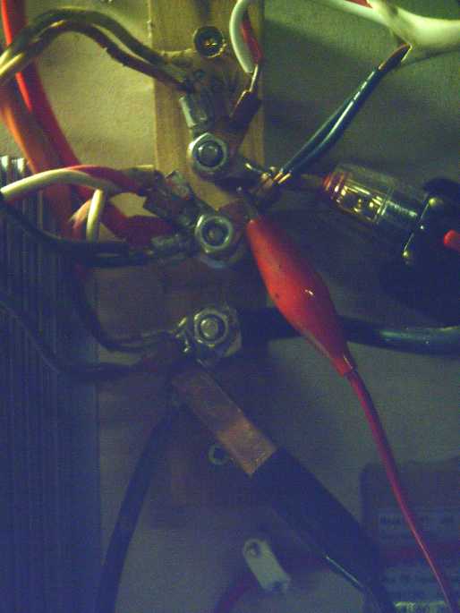 [13th] The means I had been
using to switch solar panels between the grid ties and the DC system
left a lot to be desired. Probably the PowMr charge controller could
utilize all my panels (except maybe on the brightest days of midsummer)
if there was sufficient demand for DC power. That could happen if (a) I
was actually driving the Chevy Sprint car on the highway, or (b) if the
grid power was down for an extended period of time. But presently it
would be almost impossible to wire them all up to the DC.
[13th] The means I had been
using to switch solar panels between the grid ties and the DC system
left a lot to be desired. Probably the PowMr charge controller could
utilize all my panels (except maybe on the brightest days of midsummer)
if there was sufficient demand for DC power. That could happen if (a) I
was actually driving the Chevy Sprint car on the highway, or (b) if the
grid power was down for an extended period of time. But presently it
would be almost impossible to wire them all up to the DC.
One problem was that the PowMr was a step-down (buck)
converter, and to put out ~40 volts it had to have 2 sets of panels in
series for 55-80 volts. That meant some panels had to switch between
two voltage levels. I had put up a piece of wood with 3 terminals, and
could connect the panels various ways, but it was awkward to switch
them. The terminal bolts were both too short and too close together for
comfort, and could be easily shorted. In fact, I hadn't dared to
connect the two new panels properly - just carefully with alligator
clips.
So after wanting to start
in November I finally put together a new board with more terminal bolts
and some DPDT switches that could connect solar panels (or small groups
of solar panels) to either of two destinations without having to rewire
anything.
Three terminal bolts replaced the ones on the original
board. Others made it easier to tie solar panels together into groups.
I wasn't entirely clear with what I was doing, so I left some spare
terminals and a couple of holes in the alium. switch plate to mount
more switches.


[17th] I realized the wires for the 2 solar panels on the post came
from
the right and were too short to reach to the left side of the panel. So
I wired up switch 4 on the right and connected it to the rightmost
terminals. I mounted the panel late in the evening and connected some
wires. I figured it's best done when it's dark and the solar panels
have no voltage.
[18th] In the morning I wired up the rest. I left switch 2 unconnected
for now. I added one of the new grid tie inverters (top right). With
switch 1 and
4, either or both sets of two 305W panels - on the roof or on the pole
- can be routed either to the top side (36 & 72V side) of the PowMr
or to the new grid tie. The three solar panels on the lawn go to the
low side (0 & 36V) and also to the middle grid tie inverter. They
get to fight over it. (If the grid power is off, the grid tie will use
none. If the high-side DC is switched to the grid, the DC side will use
none.)
The left grid tie inverter is connected to the original
four 250W solar panels on the roof, and they don't go to anything else.
So now up to 7 solar panels can connect to the DC system, and all 11
can connect to the AC.
At some point I may change the arrangement so all the
solar panels can connect to either the grid or the DC. Now that I have
done the whole thing, it occurs to me I could have put the triplex
T-plug plates on eac set of solar panels, and put a couple of plugs on
each of the grid ties and 4 on the PowMr, and simply plugged together
the solar sources and loads as desired at any given time. But I should
make the "click-lock" connectors with the shrouded pins for that. And
this arrangement I've just put in will be fine anyway.
If was sunny and, whether the new arrangement is credited
or not, there was more solar power than any previous day this month. It
still was nothing to speak of as it was December with the sun very low
on the horizon even at noon.
The next morning the power went off. It came back on a
little later, but not before I had plugged the fridge into the inverter
and set the two switches to provide maximum power to the DC system.
Daily/Monthly/Yearly Log of Solar
Power Generated [and grid power consumed]
(All times are in PST: clock 48 minutes ahead of sun, not PDT which
is an hour and 48 minutes ahead. (DC) battery system power output
readings are reset to zero
daily (often just for LED lights, occasionally used with other loads:
Electric car, inverters in power outages or other 36V loads), while the
grid tied readings are cumulative.)
Solar: House, Trailer, (DC@house) => total KWH [grid power
meter reading(s)@time] Sky conditions
Km = electric car drove distance, then car was charged.
November
30th 2419.40, 1092.61, .00 => 1.22 [55Km; 89444@16:30] New grid tie
at cabin but missed an hour in AM while installing.
December
01st 2420.53, 1093.20, .09 => 1.81 [55Km; 89489@16:30] Started
snowing in evening.
2nd 2421.50, 1093.20, .00 => 0.97 [89542@22:00] More snow. I
brushed snow off 2 panels on post & 3 on lawn. Sun for a while.
Cord to cabin had come unplugged... when and for how long? no power
there! Probably not much under snow covered panels anyway.
03rd 2422.13, 1093.21, .05 => 0.69 [85Km; 89608@24:30] The solar
panels at the cabin were still 1/2 covered with snow.
04th 2423.54, 1093.23, .07 => 1.50 [55Km; 89637@17:30] Sunny. Wow,
an almost clear sky late PM!
05th 2423.73, 1093.23, .10 => 0.29 [not read] Snowed in evening
06th 2424.31, 1093.74, .10 => 1.09 [89725@17:00] The snow melted off
cabin roof solar panels & 4 of the 6 house panels
07th 2424.43, 1093.84, .09 => 0.31 [89772@16:30] Rain, 1°.
Snowed overnight into 8th.
08th 2425.14, 1093.89, .05 => 0.83 [89814@16:30] Snow 1°. More
snow. I brushed off the 5 accessible panels in the AM to get most of
what little collection there was.
09th 2426.58, 1094.02, .10 => 1.67 [89865@17:30] Panels still hav
snow except the 5 I brushed off. Rain overnight, snow cleared of solar
panels.
10th 2427.17, 1094.35, .10 => 1.02 [90Km; 89906@16:30] Rain, bit of
sun. 1°
11th 2427.65, 1094.36, .11 => 0.60 [55Km; 89972@17:00] Mor Snow,
covering the solar panels again. I swept off the 5.
12th 2428.27, 1094.38, .02 => 0.66 [90034@20:30] Not much melted.
13th 2429.30, 1094.40, .04 => 1.09 [90066@16:30] Ditto. Some sun.
(-1° early, hit about 2)
14th 2429.48, 1094.41, .01 => 0.20 [40Km; 90136@24:00] Wow, could it
come any closer to 0.00? Still snow on all but the 5 panels I swept off
- melting a bit in very cold rain in evening.
15th 2430.88, 1095.08, .22 => 2.29 [90167@17:00; 55Km] Solar panels
melted off by early morning. Fair bit of sun, 1-3°
16th 2432.35, 1095.63, .12 => 2.14 [90221@17:00] Good bit of sun
again.
17th 2432.42, 1095.70, .06 => 0.20 [90268@16:30] They said
it would be a dark winter! Well, compared to many places, we have
nothing to complain about here! More lawn than snow patches now.
(Deeper snow in Port Clements.)
18th 2434.19, 1096.52, .10 => 2.69 [90305@16:30; 60Km] Sunny!
19th 2435.22, 1097.02, .15 => 1.68 [90362@16:00] Some sun. 1°
20th 2437.29, 1098.08, .13 => 3.26 [90405@16:30; 55Km] Sunny! 0°
to -1° Brr! Thick frost looks like snow.
21st 2437.64, 1098.26, .10 => 0.71 [90459@16:30] Winter Solstice.
Cloudy, dark. 1°
22d 2438.94, 0001.13, .23 => 2.66 [90511@19:30; 55Km] Mostly
Sunny again! 0°. New power meter at cabin early AM.
23rd 2439.02, 0001.18, .23 => 0.36 [90564@16:30; 35Km] Snow! --
covering panels. 0°
24th 2439.68, 0001.22, .26 => 0.96 [90608@17:30] clouds, -4°,
still snow on panels except the 5 I swept.
25th 2440.63, 0001.27, .02 => 1.02 [55Km; 90680@16:00; 50Km] still
snow, -8°, essentially it's just the 5 panels.
26th 2441.44, 0001.31, .07 => 0.92 [90756@17:00] I turned off the DC
charging (switched all 4 "upper" (35-70V) solar panels to the new grid
tie) as it's been -10°. I don't even know what lithium-ion "100%
charge" voltage is at -10°, but it might be below the 39.4V where
it is
presently sitting. High (& evening) about -6°
27th 2441.85, 0001.31, .27 => 0.68 [90815@17:00] Morr snow. Swept 5
panels again. Hit ~-1 before evening.
28th 2442.42, 0001.32, .08 => 0.63 [90868@17:00] Yet morr snow,
another sweeping. Almost got up to 0° but cooled some by night.
29th 2442.51, 0001.32, .15 => 0.24 [90930@20:00] Cloudy. Hit 0°.
Rain late PM.
30th 2443.36, 0001.32, .27 => 1.12 [90974@17:30] Bit of sun, around
0° to -2.
31st 2443.40, 0001.32, .37 => 0.41 [91033@17:30] -4,-2° again
January
01st 2443.60, 0001.85, .36 => 1.09 [91080@16:30] +3° (Yay!) Snow
melted off cabin roof & panels, but only partly off house roof
panels.
2nd 2443.70, 0002.17, .29 => 0.71 [91134@17:00] +1°. Still
snow on house panels.
03rd 2443.75, 0002.22, .05 => 0.15 [91186@16:30] -1 to +2°,
snowing, wind.
Daily KWH from solar panels. (Compare December 2021
with November 2021 & with December 2020.)
Days of
__ KWH
|
November 2021
(14 solar panels)
(2 doing not much!)
|
December 2021
(14 solar panels - all 15
contributing as of 18th.)
|
December 2020
(12 solar panels)
|
0.xx
|
10
|
17
|
18
|
1.xx
|
3
|
9
|
8
|
2.xx
|
10
|
4
|
5
|
3.xx
|
7
|
1
|
|
4.xx
|
|
|
|
5.xx
|
|
|
|
6.xx
|
|
|
|
7.xx
|
|
|
|
8.xx
|
|
|
|
9.xx
|
|
|
|
10.xx
|
|
|
|
11.xx
|
|
|
|
12.xx
|
|
|
|
13.xx
|
|
|
|
14.xx
|
|
|
|
15.xx
|
|
|
|
16.xx
|
|
|
|
17.xx
|
|
|
|
18.xx
|
|
|
|
Total KWH
|
57.43
|
32.98
|
31.52
|
Km Driven
on Electricity
|
917 Km
(~140 KWH?)
|
793 Km
(~120 KWH?)
|
|
Monthly Summaries: Solar Generated KWH [& Power used from
grid KWH]
2019
March 1-31: 116.19 + ------ + 105.93 = 222.12 KWH - solar [786 KWH
used from
grid]
April - 1-30: 136.87 + ------ + 121.97 = 258.84 KWH [608 KWH]
May - 1-31: 156.23 + ------ + 147.47 = 303.70 KWH [543 KWH] (11th
solar panel connected on lawn on 26th)
June - 1-30: 146.63 + 15.65 + 115.26 = 277.54 KWH [374 KWH] (36V, 250W
Hot Water Heater installed on 7th)
July - 1-31: 134.06 + 19.06 + 120.86 = 273.98 KWH [342 KWH]
August 1-31:127.47 + 11.44+91.82+(8/10)*96.29 = 307.76 KWH [334 KWH]
(12th solar panel connected on lawn Aug. 1)
Sept.- 1-30: 110.72 + 15.30 + 84.91 = 210.93 KWH [408 KWH]
(solar includes 2/10 of 96.29)
Oct. - 1-31: 55.67 + 13.03 + 51.82 = 120.52 KWH, solar
[635 KWH used from grid]
Nov. - 1-30: 36.51 + 6.31 + 26.29 = 69.11
KWH, solar [653 KWH used from grid]
Dec. - 1-23: 18.98 + .84* + 11.70 =
31.52
KWH, solar + wind [711 KWH + 414 (while away) = 1125 from grid]
2020
Jan. - 6-31: 17.52 + ------* + 10.61 = 28.13 KWH,
solar+
wind [1111 KWH from grid]
Feb. - 1-29: 56.83 + ------* + 35.17 = 92.00 KWH,
solar + wind [963 KWH from grid]
* The solar DC system was running the kitchen hot water
tank. Now it's only running a couple of
lights - not (usually) worth reporting. So there's just the 2 grid tie
systems:
house and "roof over travel trailer".
One year of solar!
March - 1-31: 111.31 + 87.05 = 198.37 KWH solar total
[934 KWH from grid]
April - 1-30: 156.09 + 115.12 = 271.21 [784 KWH
from grid]
May - 1-31: 181.97 + 131.21 = 313.18 KWH
Solar [723 KWH from grid]
June - 1-30: 164.04 + 119.81 = 283.82 KWH Solar [455 KWH
from grid]
July - 1-31: 190.13 + 110.05 = 300.18 KWH Solar [340
KWH from grid]
August- 1-31: 121.81 + 83.62 = 205.43 KWH Solar [385KWH
from Grid]
Sept. - 1-30: 110.68 + 65.09 = 175.77 KWH Solar [564
KWH used from grid]
Oct. - 1-31: 67.28 + 42.55 = 109.83
KWH Solar [1360 KWH from grid -- Renters!]
Nov. - 1-30: 35.70 + 20.79 = 56.49
KWH of Solar [1301 KWH from grid]
Dec. - 1-31: 19.78 + 11.31 = 31.09
KWH Solar [1078 KWH used from grid]
2021
Jan. - 1-31: 25.47 + 18.58 = 44.05
KWH Solar [1185 KWH used from grid]
Feb. - 1-28: 47.18 + 33.22 = 80.40
KWH Solar [1121 KWH used from grid]
Two years of solar!
March - 1-31: 81.73 + 55.22 + 2.2 (DC) = 139.15 KWH
Solar
[1039 KWH grid]
April - 1-30: 161.83 + 112.35 + .44(DC) = 274.62 KWH
Solar
[680 KWH from grid]
May - 1-31: 156.25 + 97.22 + 1.29(DC) = 254.76
KWH
Solar [678 KWH from grid]
June - 1-30: 197.84 + 112.07 + 2.21(DC) = 312.12 KWH Solar
[& 448 KWH from grid]
July - 1-31: 204.35 + 121.21 + 4.06(DC) = 329.62 KWH
Solar [426 KWH from grid; 150(?) KWH used by Nissan Leaf]
August- 1-31: 176.19 + 102.91 + 5.37(DC) = 284.47 KWH Solar [477 KWH
from grid; 165 KWH (est) used by car]
Sept. - 1-30: 94.35 + 51.34 + 3.30(DC) =
152.29 KWH Solar [590 KWH from grid; 155 KWH (est) used by car]
Oct. - 1-31: 77.52 + 41.85 +
4.10(DC) = 123.47 KWH Solar [1066 KWH from grid; 150 KWH (est) used by
car]
Nov. - 1-31: 34.69 + 18.92 + 3.82 = 57.43
KWH Solar [1474 KWH from grid (ouch!); 140 (est) used by car]
Dec. - 1-31: 24.00 + 5.22 + 3.76 = 32.98 [1589 KWH from grid (ouch
again! Must be the -10°'s); 120 KWH used by car]
Things Noted - December 2021
* Haida Gwaii is surely one of the worst places in the world for
collecting solar energy. In winter it is abysmal. The collection for
the whole month of December is less than that of 2 sunny days in June.
And just 2% of December's power from the grid - which with some
electric
heat is huge.
* If the panels (still) sitting propped up on the lawn (which have
somehow never
blown over) were in (wood?) frames to keep them just a bit off the
ground, the snow would come off more easily and not pile in front to
shadow the bottom cells.
* I got 3 new "no name" AC power meters from China. I wondered if they
worked both directions, that is, could tell me how much power a plug-in
grid tie inverter was putting into the wall. It seemed to work, but the
reading wasn't the same as the Blue Planet (BP) AC power meter.
Roughly, where the BP. one read 150W, the new one only read 120W - 80%
as much. That's a considerable discrepancy. Which one is right? Does
the direction, power in or out, matter? Is the Canadian Tire (CT) one
at the cabin accurate? How do I tell?
I took a new meter down to the cabin and plugged it in
in place of the CT. It seemed to read slightly higher - maybe
75 over 70 or thereabouts. The direction didn't seem to matter. As the
CT one only measures one direction and I had to rig it up with special
cords (two male ends - don't uplug the wrong end first!), I replaced
it with the new one. I'll save the CT for measuring consumption only.
I guess it's the BP one that seems to be reading a little
too high. Perhaps
I should replace it too?
Annual
March 2019-Feb. 2020: 2196.15 KWH Solar [used 7927 KWH from
grid]
March 2020-Feb. 2021: 2069.82 KWH Solar [used 11294 KWH from grid]
(See TE News #156 for the two year writeup... which technicly should
have been two months earlier.)
https://www.TurquoiseEnergy.com
Haida Gwaii, BC Canada