While nothing more is actually finished and ready to use, this newsletter is simply packed with strong progress in several areas and also holds what I believe to be a fantastic idea for a new government organ, the "Department of Inventive Progress".
Early in the month I made excellent progress with design and tools for home or small scale fabrication and formation of alkaline or salt batteries, whatever chemistry is chosen for the electrodes. Not only was the case former improved and an acceptable large "seamless body" case produced, but a solution to another intractable problem, compacting electrode materials into briquettes, was found and the press made. As so often happens, complex and expensive solutions were being visualized (hydraulic press equipment) while a practical, simple solution (torque down some bolts) was just a concept away. I suddenly visualized that solution in the first days of October.
The lead-acid battery renewal project proceeded apace, a couple of dozen battery cycling tests being run. Yes, it would seem lead-acid batteries now can be de-sulfated - renewed - fixed - and made long lasting - simply by adding an electrolyte additive: sodium sulfate salt. There is good promise that they will potentially last 3 to 5 times as long as previously, ten or twenty years instead of three or five. This suddenly makes them a much more practical choice for off-grid energy storage and electric cars. The prognosis is so far based on other peoples' good results with alum plus seeing that sodium sulfate is chemically the better salt. So simple it seems just too good to be true, but there it is!
I've been publicizing it on some battery related chat lists to spread the good news, gratis, hopefully far and wide. There is skepticism. Experiments continue to determine best quantities to add and to put actual performance figures to the "anecdotal evidence", but firm figures to convince the skeptics, especially for increased life span, will take time and effort, and it's not my prime focus. The project could really use a full-time researcher... perhaps a university grad student.
It dawned on me that the government is missing an organ, a "Department of Inventive Progress" overseen by a government minister, and that that lack is a major stumbling block in advancing civilization, from doing things from adopting concepts for improved and updated methods of government when good ideas appear, to paying inventors so original inventions happen, and then liaisoning with industry for commercial adoption to ensure that they aren't cast aside and wasted once invented. (Another great example of an invention cast aside with no one looking out for the public interest also came to light this month: George Constantinesco's 1923 Mechanical Torque Converter, which I write more on in this newsletter.)
I spent a couple of weeks on the project of writing and explaining the idea in some detail to Canada's Minister of Finance with whom I had had previous correspondence on the subject of funding for inventors. I CC'ed to my M.P. Dr. Keith Martin, who had put me in touch with the minister, and to the Premier of BC, to whom I had also complained earlier about the complete lack of funding. Whether this effort will bear fruit I don't know, but I've now done what I could.
I also offered to speak on the subject, "Hidden Barriers to Inventive Progress and the Government's Missing Arm" at Island Tech '09 on November 13th following their request for speakers, but was turned down.
As I was spending my time writing, I was also considering how best to make the magnetic torque converter work. The project details evolved considerably in my head up to the last week of October without building anything more physically, and I felt I now had a more or less final design for a prototpye that would actually drive a car. I started making it on October 25th and got the basic assembly made that day. Construction goes faster when you know what you're building.
Then on testing simply by turning the rotors by hand, new design ideas arose one after another, and the "moving target" plan shifted yet again. Now the torque converter will use masses and inertias and no magnets, and so will be mechanical rather than magnetic. Looking up that idea revealed that mine won't be the first mechanical torque converter, and that their performance is simply amazing. Using one will surely allow a 5 HP electric motor to run a car. Mine will be the simplest one to make and easiest to understand, with the fewest moving parts - one. That's not counting the input rotor (which is the motor) and the output rotor (which is the car wheel).
November holds considerable promise for definite results!
the government's missing organ
Canada's Minister of Finance, the honourable James M. Flaherty, had replied during the summer to a letter I wrote in the spring about the possibility of getting funds to be made available to inventors via an inventors professional association that I had proposed and tried to organize.
My letter followed, first, my e-mail to my M.P., Dr. Keith Martin, which was simply a "FYI" about trying to make an association, and then, a letter that Dr. Martin wrote to the minister on the subject. (Dr. Martin had tried unsuccessfully to find me funding for the wave power project a couple of years previously.) I saw that his letter didn't explain things in sufficient detail to be likely to cause the minister to act, so I followed with my own.
The reply showed the minister, like most everyone, had no idea what the problem was or that there was a problem. I spoke of support for "inventors" and "inventing", but his reply spoke of Canada's support for "businesses" and "business innovation", as if they were the same things. Meanwhile I had found there weren't enough inventors around with the interest and the time to try forming an association and had given up the idea.
I just thought, "Well, that figures - no point pursuing that!" For quite a while I let the matter drop. This month I was using the back of the minister's reply letter as scrap paper to write some battery test results on. Seeing the letter again I thought, well, nothing ventured, nothing gained - why not write again and try to explain better?
I would describe how inspired individuals invent new solutions, not companies (and still less "consortiums of companies" per SDTC), and how impossible it was for inventors to actually access funds that were supposedly made for doing "innovative" things, forcing them instead to find other work that would allow them to live and eat.
And for an excellent example of how government was unable to recognize solutions and act to bring about the very progress it was trying to achieve, I had no farther to look than my own recent experience. How absurd was it that $10,000 couldn't be had by - surely - one of Canada's most experienced and accomplished inventors, to prove that a practical design of floating ocean wave power units would work. If it did, it could well save three billion dollars and a major tract of Peace River valley land? I had taken the case to my MP and the BC Premier's office - the highest levels of government short of the prime minister - and no one could suggest a source of funding that proved accessible when investigated.
Early in the writing, inventive inspiration struck. I suddenly realized the problem is that the government is missing an arm!
Both the education department that funds university research and the department of industry that funds corporate developments feel, probably rightly, that inventors, inventing, inventions and the progress of society and civilization are outside of their mandates - hence the non-support for inventors. There's no Department of Inventive Progress headed by a government minister to enable and foster the advancements the government and people want to happen.
No one notices it's missing - the store shelves don't empty, there's no disorder on the streets. But the effects of its absence have gradually shaped our world.
For example, we've all wanted electric cars for decades. Inventions help, but there's never been a technical barrier - there were electric cars before gasoline cars - what has been the hold up? The Department of Inventive Progress would not only fund promising inventions, but make sure that once invented and proven they don't go to waste, get spirited away by "dog in the manger" vested interests or tied up in government red tape. It would identify and work to overcome barriers to adoption of desirable technologies and ideas, to enable, foster and ensure motion towards progressive goals.
My letter proceeded along those lines. I spent a couple of weeks on it, with supporting documents. I sent "CC"s to Dr. Martin (one of parliament's top speakers and legislators) and to the honourable Gordon Campbell, Premier of BC. Whether it will bear any fruit, I can't say. But I think it's the right idea, and I'm glad to have taken the time to figure it out and to say it.
This has general applicability as well as specific. I'm writing it up because I've read it's "not really possible" to disassemble epoxy glued parts once the epoxy has set, and there are in fact ways to do so if it's important enough. My brother Stuart, a biochemist, suggested trying vinegar or amonia. I won't do "1, 2, 3" instructions as situations will vary.
The first couple of times I had to remove supermagnets glued to a steel rotor, I put the rotor in a bath of vinegar for a week or more until the magnets were loose. But the magnets were quite corroded by the acid by that time.
Then I tried sodium hydroxide, again for a week or more. The steel metal and the supermagnets didn't corrode in that, but it didn't seem to work as well. Here I first put a 14" crescent wrench across the magnet and tried to twist it.
Then I hit on "Draino". It has sodium hydroxide plus some other chemicals. That seemed to work as well as the vinegar or better without corroding the metals. I think I dumped in about 1/3 of the can into 3 or 4 liters (quarts) of water.
These chemicals don't dissolve the epoxy, at least not on the time scales I used, but they soften it enough to make it possible to break the parts free.
The next time, I didn't want to wait a week if I could possibly help it. So instead of a plastic bucket, I put the rotor and Draino solution into a big canning pot and simmered it on the stove for a few hours. (I put in an aluminum chunk to keep the rotor magnets from clamping onto the bottom of the pan too hard. The aluminum corroded quite badly. (oh ya... aluminum in sodium hydroxide is a no no - perhaps the vinegar is a better bet for aluminum parts. I haven't tried it.))
I took it outside, pulled out the rotor and hosed off the chemicals, then I put the big crescent wrench on a magnet and hit the handle with a hammer. Most of them came loose with the jolt, but a couple of magnets shattered. To get the very last one of these off - I should say its remnants - I put it back and simmered it a while longer and then soaked it overnight in the Draino solution. Then it/they came off.
Sodium Hydroxide and Draino are dangerous chemicals. They can burn your skin and blind you. ("Blindness is forever" - chem prof.) Wear face/eye protection and rubber gloves.
I had an accident regardless of precautions when I picked up the pot: the magnets yanked out the stove burner, ring and drip pan, and then dumped the burner face down on my kitchen floor. It had been on low, but it was enough to burn a black spiral into the beautiful lino. There's a warning if you use this technique to unglue a magnet rotor!
October In Detail
The design for the Electric Hubcap motor and the (updated) design for the Turquoise Motor Controller are on the web. They are "finished" as far as the original intent to make a motor and controller that work for the drive system. I updated the motor controller manual again this month with a clearer schematic of the power MOSFET transistors and supporting components of the heatsink area.
A system to propel a car now only needs a working Carmichael Magnetic Torque Converter, the subject of the next section. The motor and torque converter unit now weighs about 56 pounds.
I was finding that the motor didn't want to start going very well on the bench, and I mistakenly attributed this to my "skip tooth" magnet configuration. In fact, the problem persisted when I'd changed to just six whopper 2" x 2" magnets. It was actaully swapped phase power wires to the motor, ie: BCA instead of ABC, when I wired up the new APP connectors.
Come to think of it, it was working just fine with the "skip tooth" magnet arrangement on the car previously.
It's too bad I didn't recognize the problem before I changed the magnets: the "skip tooth" configuration didn't get a fair trial to see if it might in fact be superior, similar, or not as good. However, having come up with a way to soften the epoxy glue and get the magnets off a rotor in a day opens possibilities for trying things like that out more easily.
Magnet spacing options worth comparing:
* The six double size magnets
* Six pairs of regular (2" x 1") magnets, all twelve evenly spaced around the rotor.
* The "skip tooth" arrangement with 18 positions, 12 occupied: NxNSxSNxNSxSNxNSxS.
* Close regular magnets in 18 positions (6 gaps): NNxSSxNNxSSxNNxSSx. (Not so different from the six big magnets.)
One of these might have highest starting torque, another might have more even torque, etc.
I've decided to order some hall effect sensors to try out, as they appear simpler to install and use than the optical position feedback system.
It seems the MC33033 brushless motor controller chip is to be discontinued, but it also seems I've missed seeing some more recent chips that may be better.
I looked one up that appeared it could be quite good and would be a single chip solution, as it has the high-low mosfet drivers built in. (Only good for 50 volts instead of 200 or 600... but this is a 36 volt motor, so hopefully it should just make it.) Maybe I can find one with regenerative braking built in!
I'm not looking forward to designing a third circuit board, however.
It occurs to me that with a measured 25 pounds of force required to pull a small steel cylinder away from a supermagnet, when only a line of metal is in contact, the force needed to pull two clamped together supermagnets straight apart must be at least hundreds if not 1000 or 2000 pounds. This potential crushing force is why it's a serious hazard to get a finger between two of them.
Here's a little anecdote to show how innocently magnet accidents can happen.
In the rotor work for the magnetic torque converter, I was working in the kitchen because there are simply too many metal things around in the shop. I was sanding the (previously used) magnets clean and setting them 16 inches apart on the kitchen floor preparatory to epoxying them on. I decided a couple of them were too much in a traffic area and should be moved elsewhere lest I kick one.
I went to pick them both up to move them... both at once in the same hand. Oops! Of course, this did the very thing I most wanted to avoid: brought two magnets together, with my fingers there. Luckily I wasn't gripping the first magnet in my hand very strongly, and it jumped out of my hand as the two clapped together. Neither one shattered, and I used the jig (see torque converter project, below) to get them apart.
I wonder if it might be good safety policy to get some tongs (eg stainless steel or plastic) and always hold the magnets with the tongs, never touching them by hand at all. I can also see this would make it awkward to get them off the strip, apply the epoxy glue, and get them onto the rotor. I mostly handled the big 2" x 2" x 1/2" magnets with pliers, except when I was applying the glue. Stainless steel or other non-magnetic pliers would have been much better if there was such a thing.
Then when you're done, there's the dangerous rotor with a bunch of magnets all on one or both faces, capable of clamping onto a piece of metal with several tons of force!
Mechanical Torque Converter Project:
Torque Leverage Without Gears
September Details
This writeup became something of a diary, with ideas coming fast and furious throughout the letter part of the month. I cleaned it up a couple of times to reflect the latest thoughts... and then more ideas came, making what I'd just written a day or two before obsolete.
While writing the letter about the "Department of Inventive Progress", I kept thinking at odd times about how the magnetic torque converter might work.
I had had the inspiration that magnetic pulses should provide short moments of high torque, while for the remainder of the motor's rotation, it would have no load and thus would be able to resume its speed in order to impart the next torque pulse.
Then for some reason, I intended to put six pivoting magnets on the output (wheel) rotor. Since there were ten magnets on the input (motor) rotor, five of each polarity alternately, each magnet would produce its torque pulse at a different time, many times (30, I expect) per motor rotation. That would be smooth, but it would just average out to more pulses of a fairly low torque instead of producing the highest possible peak torque and then motor speed recovery time.
What's needed is the torque pulse of, eg, five magnet attractions at once, to get the car to start to move. So now I've put five magnets on the output rotor instead of six, and five attracting magnets on the input rotor. These will all meet at the same time, five times per revolution of the motor. Five magnets at once will naturally give five times the torque of a one magnet pulse, one fifth as often. It will then be five times as hard to hold back the car wheel and prevent it from starting to turn. (It is unnecessary to twist the magnets per last month's idea; they are left "on the flat", which will work equally forward or reverse.
Since all the magnets were now to act together, they wouldn't need to be on separate pivots: the entire plate of magnets on the output rotor can move at once, and has become the "slip plate".
This is the first arrangement I've hit on that would surely have enough torque to start moving cars up hills and accelerate them well, rather than just gradually get them moving on level ground.
The next idea was that instead of moving the output rotor magnets up and down, the plate holding them should be free to turn a couple of inches, to twist back and forth relative to the car wheel. Here's the sequence of operation, and for simplicity we'll say the output rotor doesn't turn:
1. The input and output magnets aren't in close contact. The motor, spinning freely, picks up speed.
2. The magnets of the input rotor start to overtake the output rotor magnets. As they attract, the output rotor magnets are pulled backwards. The magnet plate twists freely until they line up with each other. No backwards force acts on the output rotor and car wheel.
3. As the input magnets continue to turn, the plate starts twisting back again, with the output magnets freely following the input magnets.
4. Then the plate hits its end stop. The output magnets try to continue to follow the input magnets. They can't unless the wheel turns, but the attraction is very strong, and a whopping torque pulse is produced. The motor loses speed at this moment. Some of its momentum energy is transferred to the output rotor, the car wheel, which tries hard to turn. (If the wheel is turning and not too much torque is required, motor and wheel lock together magnetically here, providing a lossless direct coupling.)
5. The input/motor magnets pull away from the output magnets, then the motor starts to pick up its lost speed.
6. By the time the input magnets start to overtake the next set of output magnets the motor has regained its speed and all repeats, every 72 degrees of rotation.
This works equally rotating either direction. The magnetic pulses all pull in the direction the motor is turning. The spots where "equal and opposite" force should be pulling backwards are nullified by the free twisting of the magnet plate, like a bicyclist pedaling backwards.
The faster the motor is turning, the less time there will be between pulses for the car to try to roll back to where it was. But even at just 300 RPM, there are 25 torque pulses per second.
Towards the end of the month I considered the mechanical details for an actual prototype output rotor implementation. There seem to be at least two considerably different main arrangements to achieve the above effect: to have the magnet plate slip back and forth within the frying pan, or to have the plate affixed and make some bearing & stops arrangement at the center shaft to allow the entire assembly to shift back and forth.
I selected the former as being the easier to make, and also the slip pins (or whatever), which will suddenly hit their end stops as the motor turns, will have much less torque pressure behind them at the rim than near the center, reducing wear and tear.
Nevertheless, I'll probably have to beef up the aluminum slot ends with some strong spring steel end-stop springs or something. But before I get too fancy I'll try it out as is to see how it works.

The magnets clamp themselves magnetically to steel.
Aluminum is a different case!
Later it was found that the epoxy didn't really adhere to the aluminum regardless - magnets simply fell off under stress.

The magnet slip plate assembly.
(Before mounting the magnets.)
On the 25th I made the pins and their mounts, and cut the slots in the frying pan rim. That's the main assembly. Then it occurred to me that to compensate for having the extra magnets stuck on the input rotor, I could widen the slots and allow the slip plate to rise up and somewhat away from the repelling magnets "giving them a miss" and only use the attracting magnets.

The complete output rotor.
The four black bolts hold this rotor and the axle, and hence the entire system, to the car wheel.
I had made the input rotor earlier with 10 magnets, 5 of each polarity alternating. But the more I thought about it, the more I liked the idea of just having the same few magnets, all the same polarities, on both rotors. That way, the motor has the most time to speed up between "all alike" torque pulses, which can be set to be as strong as desired with the magnet sizes and gap. On the 26th I finally decided to bite the bullet, get the magnets off the rotor, and start again.
I put the rotor in a solution of Draino and water. From previous experience I expected I'd have to wait a week or so for the "epoxy steel" glue to loosen, delaying the final assembly until November. Then I thought, hey, why not heat the water - simmer it? That'll speed up the reaction, and the motions of the water will get the stuff in under the magnets better.
A "magnet accident" occurred in this. First, to put it on the stove, I had to put the rotor in a big steel canning pot rather than a plastic pail. I put a chunk of aluminum on the bottom so the rotor wouldn't clamp down flat magnetically in the pot. Then I put it on the stove, and it glommed down on the metal stove and became hard to move. After a few hours, I went to take it outside to see if the magnets would come off.
When I pulled hard enough (on a pot with caustic soda and a supermagnet rotor - yikes!), it came off -- complete with the burner ring, the drip catch piece and the burner element, which then fell on the floor, face down. It had been on "low" and the water wasn't boiling, but by the time I'd set the pot of hazardous chemicals and magnets down safely, the burner had melted a nasty black spiral in my beautiful near-new kitchen floor, one of only two really nice looking floors in the whole house! Visual appeal isn't my strong point, but this made me feel rather sick.
The magnets mostly came off, but I broke the second one. My technique is to get the magnet in the jaws of a 14" crescent wrench, then hit the handle of the wrench with a hammer to twist the magnet and break it loose. I hadn't quite closed the jaws and so the pressure was on one corner and the middle of the other edge instead of spread out. I got it off and was more careful after that, but one of the last ones simply wouldn't budge. It crumbled into pieces. All ready to go in just one day, except for this one chunk of rubble still glued solidly to the rotor! (Anybody want some strong, jagged fridge magnets?) I put the stove burner back together, put the rotor back in, boiled it a while, and then left it to sit overnight. It came off the next morning.

Magnet rotor with the first three 'whopper' 2" x 2" x 1/2" magnets installed.

I used pliers pulling these magnets off the strip, and it wasn't easy.
I got two pairs clamped together and had to make this wooden jig (arbutus, no finish) to separate them by sliding them apart. I used the radial arm saw to make the grooves and then chiseled out the squares. (Note the distance between the pieces & magnets - they're only this close together for the photo!)

When installing the second three of these extremely powerful magnets, prudence required making sure they couldn't glom onto the nearby ones by fully covering them. (Rosewood sapwood with painted ends.)
Always bring the magnet straight in to its position, not near the rotor on the approach.

Finished motor side of the magnet rotor.

Assembled for a motor test run before installing torque converter magnets.
(shown without motor stator)

Re-magneting the torque converter side. The spacers were required as the magnets all tried to slide up against the center hub until the epoxy set.
(Here I didn't cover adjacent magnets as they are well separated. Note the foam safety cover, held in place magnetically with sheet steel, over the magnets on the other side.)
When I put the two rotors together on the shaft, I found it impossible to turn them relative to each other by hand. It seemed like plenty of magnetic coupling to turn a car wheel. They went together violently, and I had to use wooden wedges and spacer pieces to separate them enough to pull them apart.
On the evening of the 29th I made a spacer to slip onto the axle before the bearing, to keep the rotors farther apart. With a gap over 3/4", I was able to turn the two pieces against each other by hand. As long as there was slot travel, the plate would follow the motor rotor rather easily, but on reaching the end of the travel, there was about a 1.5" range where I could barely pry them into going further - the torque pulse area. So that's around 7.5" out of about 37.6": 20% of the total range where the motor supplies torque, and 80% where it gets to pick up lost speed. The maximum torque boost thus works out to perhaps 5 to 1. With direct drive to the wheels, even Electric Hubcap motors on all four wheels would have less punch for starting the car moving than just one with the torque converter.
Well, that was the result at first. Then things got strange: the forces dropped way down and there was the sound of things sliding around when the rotors were twisted. Sure enough, three of the five output rotor magnets had come loose! The other two I tapped off easily with a hammer. I guess "epoxy steel" doesn't stick to aluminum.
My main concern is that it may be hard (read "not possible") to start the motor turning against the powerful force in the torque pulse area. And the motor is bound to come to a stop in that very position almost every time.
But the test, turning the rotors by hand, led to more observations and ideas...
I note that there's a bit of lifting (ie, repelling) force when a magnet is held between two of the output magnets rather than over one. Perhaps it will be beneficial to arch the slots so the slip plate can "rise" away from the input rotor during its turning.
A separate thought is to force the slip plate up with an arch just before it hits the end stops. That way, the stops would be gradual, gentle, instead of simply a sudden hit at the end, and perhaps that's a key to having the motor able to start turning, without losing the essential wheel turning torque.
Then on the 30th I had a substantially new idea, and the more I thought about it, the more new ideas started flowing in all day. I've been keeping the twist plate light. What if, instead, it was made rather massive, so when the pins hit the five end stops, much of the torque is developed from the impact of the mass of the plate, rather than directly from the magnetic fields. That way, the field only has to be strong enough for the motor to carry the heavy plate back and forth, not to develop the actual wheel-driving torque. Any torque ratio might be achieved, and the magnetic fields could be kept light enough not to hold the motor stalled regardless of stopped magnet positions.
It's conceivable with this design that one could possibly use the motor rotor itself as the slip plate, driven back and forth in a complex sequence with a computer program, and "hitting" the wheel at only one or two points of revolution so it could get some speed up before the hit. Yikes! On the other hand, the motor needs to spin to really get up speed and develop power.
So I thought I'd stick with the present three piece design, but add mass to the slip plate.
Another thought was: if all the magnetic fields are attracting fields, and if they are too strong anyway, why have supermagnets on both rotors? Why not just have steel blocks in their place on the output rotor? Heavy ones to give the desired mass?
Then the next idea came in. If, instead of end stops, the slip plate pins hit 45 degree slopes, there'd be flat "high" areas and flat "low" areas, with 45 degree slope points in between. The plate would be free to turn with the motor rotor. Each time the pins hit a slope (all five at once), the plate would shift "up" or "down", and in the transition, some of its rotary energy would be transferred to the output rotor, especially if the plate was massive. If the magnets were strongly attracting, most of the force would be developed on the "up" slopes while the "down" slopes would be a free ride. Once again, it provides short spots of torque with long areas where the motor has no load. It's a variant of the "clock escapement" mechanism mentioned last month.
These ideas led to the next thought: If the plate simply rotates with the motor rotor, why have a separate plate at all? Why not just mount the pins on the motor rotor? Or, mount the plate on the motor rotor, rotating with it but free to move in and out?
And then, what are the magnets for at all? why not just use springs? or even, why not just make the pin mountings or plate massive enough to impart their kinetic energy at the 45 degree slope points without any particular springs or magnets forcing them one way or another? The stopped motor would be free of any notable starting load no matter what the relationships between the stopped rotors. Since E = 1/2 M * V2, the torque developed would be a function of the motor speed squared, as it ought to be.
With several attractive designs suggesting themselves at almost the end of the month, it was obvious there would be no electric car test drive in October, the anniversary of the motor first moving the car across level pavement. I feel like I've just gone through several generations of torque converter designs, any of which might be made to work, more in my head than actually built.
Then there was the thought that if no magnets were needed, it went from being a magnetic torque converter to a mechanical torque converter. I started thinking, "wow, if it's just mechanical, if it doesn't need supermagnets, it could have been invented long, long ago, but it wasn't!"
Or was it? A web search on "torque converter" had turned up only hydraulic ones (as far as the eye could see). Then I had looked up "magnetic torque converter", and though I found a couple of patents by that name, I didn't find anything that actually was a torque converter as such - they were just magnetic-tooth "gears".
Not so searching for "mechanical torque converter"! It seems the first design - nothing like my latest concept but achieving the same effect by similar means - masses and inertias - was created about 1923 and an efficient automatic transmission car (no gears!) was made, and later, locomotives and other applications! So, it actually was invented rather long ago! And there are some more recent patents. (What's the betting they've all been acquired by oil companies and stuffed in closets?)
So possibly I may be re-inventing the wheel, but looking over a few of the designs, at least I hope to make a much simpler, easy to make and to understand wheel, and my work will be unpatented "open technology" available now, not in 2028 or so.
And, lets not forget the people trying to create "continuously variable transmissions" with belts and pulleys since the 1970s. Laudable, and progressive compared to what's actually in use, but this far superior solution had already been around for the taking for 50 years - now it's headed for 100!
By the morning of the 31st, I'd decided on a specific design (unless another new idea hits before it's made!):
The torque converter will be mechanical, not magnetic. The plate - now an "inertia plate" - will rotate with the motor rotor, mounted on six posts (smooth bolt bodies, between the six magnets on the motor side of the rotor) that will allow it to shift up and down as it turns. There'll be a steel slot just inside the rim of the pan that the ends of the pins will ride in, which will have a 45 degree bend, every 36 degrees around the rim (10 bends), alternately "up" and "down". The pulse of torque each "hit" on a 45 degrees bend will produce would depend on the motor speed (squared), and will be adjustable by changing the mass of the plate, adding or removing metal from steel blocks. There'll be no resistance beyond slight friction to starting the motor to turn. Thus it will never be stalled. The load on the motor will increase exponentially with motor speed. (More precisely, with the difference in speed between the motor and the car wheel.)
45 degrees is the angle the watch makers say imparts the most energy with the least amount of friction. It may be desirable to use ball bearings on the pins to further reduce friction. Here's the path of the slot around the rim of the pan, causing torque by repeatedly forcing the inertia plate to suddenly shift sideways:
_____ _____ _____ _____ _____
>__/ \_____/ \_____/ \_____/ \_____/ \___<
Now to get those magnets off the rotor... again! ugh! (or should I just keep them there, just in case they'll turn out to have some use next week?)


George Constantinesco's Mechanical Torque Converter: First Prototype, drawings, 1926 automatic car (with improved version of converter).

There's even a Meccano Set version for kids,
...but not one in your car!
Here's some text describing the impressive capabilities of the mechanical torque converter:
(from http://fluid.power.net/fpn/const/const005.html )
"George first successfully tested a Torque Converter in a car in May l 923, using an experimental model that had been built only for bench tests. He obtained an old Sheffield Simplex chassis and replaced the big 45 hp engine with a 10 hp "light car'' Singer engine, and built a platform on the chassis. This car was driven around the outskirts of London loaded with 10 people, including the inventor at the wheel, fig. 21, and later towed a lorry [truck] up a steep hill. As a further demonstration of the capabilities of the car, six inch wooden blocks were placed in front of the wheels. When the accelerator was depressed the car climbed over the blocks smoothly and without hesitation, to the astonishment of the bystanders. This test was merely to demonstrate the possibilities of the Torque Converter, because even a 10 hp engine was much larger than necessary for the production car envisaged."
That I'd never heard of a "mechanical torque converter" before conceiving one myself is a good demonstration of how information on the web is easy to locate... IF you happen to know exactly what you're looking for and exactly what search terms to use.
It's also a good demonstration of how good inventions get sidelined and collect dust on the backs of shelves. The mechanical converters have high efficiencies, and they can be made with wide conversion ratios that completely eliminate the need for transmission gears. ("Forward" and "reverse" gears for gasoline engines were done at the rear axle where there are other gears anyway, thus with no extra transmission gearbox and its added weight and inefficiencies. Electric motors on wheels will run either direction and independently, eliminating all need for gears.)
It's apparently superior in all respects, yet the automotive industry rejected it. In fact, General Motors made a lucrative sounding agreement with Constantinesco that prevented him for some time from going to other car companies with the product, but "then" chose not to make them - no doubt their plan all along - and the lack of the agreed and expected royalties left him in financial trouble. It probably wasn't the first, and certainly wasn't the last, time the big automakers have acted in bad faith and contrary to the public interest.
The industry chose instead, and continue to choose, much larger engines than otherwise necessary, driving wasteful fluid converters coupled to wasteful gear systems that need gear shifting: giant, heavy dinosaurs requiring operator attention and with an overall 30-40% loss of power (per Wikipedia etc.) in the drive train.
Unbelievable! Why are we bailing out these corrupt, moribund automakers when their ships are full of gaping holes and they don't lift a finger to repair them until water is pouring into the bridge? Instead, why not fund creative people having ideas and ideals, people like Constantinesco perhaps, to become innovative auto makers and bring progress and new industry? The 80 million dollars just in bonuses that the 50 "top" stuffed shirts at Chrysler awarded themselves last year alone while their company was going down the tubes could have given someone who actually cares a very good start!
Here we can guess that a government "Department of Inventive Progress" would have been known and understood as the proper place for Constaninesco to submit the prospective design, hopefully it would have recognized the amazing potential, fostered development into a practical product (ie, contracted him to make it and paid him the trifling sums needed to enable him to create, prove and improve his design and live a normal life), and then finally ensured the torque converter would find its way into vehicle use to supplant the dinosaurs, whether by means of existing companies if they co-operated willingly, or by fostering new, more progressive companies to take over.
October Details
Design Decisions: sizes
After finding that the 1/4" thick ABS plastic cases needed to withstand considerable pressure to have a sealed battery, I previously settled on 3" wide electrodes as being (a) an even divisor of the 6" x 12" purchase size for nickel-silver or nickel sheet metal and (b) the widest size likely to handle the pressure well.
Then I thought I might as well simply split the sheets in half and have 3" by 12" electrodes. But now I think that's just too much to deal with at a time for home manufacture, and I'm shrinking it (at least for starting out) to a more managable 3" by 6". I have made an electrode compacting jig for that size, the latest and most fantastic tool for home battery making (below).
The newly made battery case forming jig (below) will handle 13" cases, but I'm sure 7" long cases will be easier and luckily no modifications are required.
With the 3" ABS pipe, it seems to work out that forming it to 3-1/4" wide about a 2" width is obtainable, for eight 6mm thick electrodes: four bipolar cells or quadruple prismatic plate sets.
Voltage of course depends on the chemistry chosen, but bipolar cells would make a battery with four times the voltage, eg, 2 volt cells would make an 8 volt battery, while prismatic construction would make a single cell with four times the current capacity of a single pair of plates.
For a "dry cell" with limited (non-flooded) electrolyte, the bipolar "battery pile" construction is preferable because there are no internal welded connections to potentially fail except one to each terminal post.
In looking at the Alkaline Storage Batteries book by Falk and Salkind detailing the state of the art in 1969, 3" x 6" electrodes seems more than ambitious. Pocket electrode briquettes were usually made 9 or 14mm wide and about 4" long (Edison's & Jungner's original size, I think), and this size of small pockets were combined into flat electrode plates maybe 3" by 4" or so.
I can go back to 3" by 12" (or other chosen size) later if desired by making a new electrode compacting jig for that size.
I improved the torture rack for stretching three inch I.D. round pipe into 2+" x 3+" rectangular. This forms it, stretching the 9.43" inside radius to about 10.75" to get the desired size rectangle. Hmm - that adds 1.3", no wonder the screws are hard to tighten sufficiently!
It seems to take 3 or 4 times, tightening the screws a bit each time, heating for an hour in the oven total. Perhaps I'll try getting it hotter next time, say 350ºF, and see if it's easier to work with. I've gradually gone up with each case, from 285º to 300 to 325. Of course, I'd rather it didn't melt down -- and I really don't want it to catch fire! At 325º leather gloves are just adequate for turning the thumbscrews, but they might take less turning pressure at 350 if the plastic is softer.
Another idea to try is to set the nuts so that when the right size is reached, they're all the way in, touching the metal tubes. That way you'll know when you're done without taking several measurements, and the size will be more consistent. (The hex nut and the wing nut are strongly tightened against each other to make a solid "bolt head", and they can be set anywhere on the threaded rod.)

"Case Former - Mark 2" to make round 3" ABS pipe rectangular.
The plastic is heated in a kitchen oven to soften it (~325ºF), then the screws are turned in until the pipe is square and the desired size. Weights with aluminum top and underneath plates make the long sides flat. Two new pieces (not shown) are to be inserted in future to prevent the ends of the long sides from bending inwards in the middle.

The case, ready for bottom cover glueing.
I'd rather put in a gasket and screw on the top cover. That would make the batteries potentially repairable.
Interior size is 2" x 3-1/4" x 6-3/4" for four bipolar (or prismatic) cells with 3" x 6" electrodes plus electrode side, top and bottom clearances.
This version has the wing nuts all on the outsides where they are easily accessible. Only two long bolts have to be unscrewed to insert the rack through the 3" tube before forming.
A great answer hit me as I was considering possible pocket electrodes (below): How to compact the electrodes? Screw it! Sandwich the electrode between two pieces of steel with many bolts all around the edges. Oil the bolts and screw them up a bit at a time until they just won't go any farther. If there's enough bolts for the plate size it should end up as a well compacted electrode briquette!
Wow! So there's the multi-tons strength press I've been wanting all these many months! Another of the several intractable battery making problems is solved, suddenly and simply!

Electrode Compactor
To make an electrode, a nickel-silver or nickel electrode collector plate (A) is covered by fine stainless steel mesh (B). The 12" plates to be connected to the terminal posts are cut especially in half by hand "jogged" to make a tab (f) to weld to the post. The missing bit on each side taken for the other tab (g) is filled in with a small scrap of the same sheet metal under the mesh (h). The mesh is cut a little bigger than the plate and is wrapped tightly around all four edges for good connection between the active electrode material pressed into it and the collector plate. For a two-sided electrode, the mesh is wrapped all the way around. (This leads to the thought that the metal sheet is perhaps not even needed for interior electrodes - it could be a mesh-wrapped plastic sheet. Cheaper!)
The ready electrode plate (C) is placed in the bottom of the compactor and the active material paste (of whatever formulation) is scooped in and spread evenly. Depending on results, the edges may if required be lined with plastic to keep the material from sticking to the sides.
A plastic liner and then the punch plate (D) is placed on top of the electrode "stuff" and the lid (E) on top of that. The screws are inserted and gradually torqued tighter and tighter to compact the electrode material into a solid briquette that is embedded firmly into the conductive mesh.
Then the screws are removed and it's just a question of getting it out in one piece. If I make one end wall removable, a spatula or whatever can be inserted under the electrode to pry it up.
The electrode thickness depends on the amount of paste and how much it compacts. The sides of the press are 1/2" tall, and the press plate is 3/8" thick. If the finished electrode is less than 1/8" the press plate will need a spacer. If it all gets too thick - more than 1/2" of uncompacted material is required or if it's the second side of a thick two-sided electrode - I may need to replace the sides with taller ones, or put extender sides above these. (Hmm, I do have 1/4" and 3/16" side pieces for extenders - left over from the previous design. Problem solved!)
Wanting something simple that actually works just to say it does, I keep thinking of the old "pocket electrodes" used since Edison's time in alkaline batteries.
The stopper is not having perforated nickel sheet or tube. (I e-mailed a company that says they make them in August, but they didn't reply.) I have the nickel silver sheets, but drilling hundreds of holes in a sheet would likely just waste all the fine drill bits the hobby shop has. I found perforated brass sheet at the hobby shop, but that would corrode quickly and attempts to nickel plate it have been unsatisfactory - then when I cut it the new edges would need replating.
I thought a couple of times of the #60 stainless steel mesh as a "perforated sheet", but it's about 80% open space and I know the electrode material would simply make its way through.
But I started thinking "if only they made it with flat pieces of stainless instead of round, it would be like a flat wicker basket and mostly closed space." Then I thought, "Hey! Why don't I take a piece and flatten it in the rolling mill?" (Hmm... stainless steel... well, the rollers have hardened steel faces, which *should* be harder than stainless and they *shouldn't* dent... theoretically!)
After several runs through the mill with two (very rapid) annealings with the propane torch, the mesh wires were flattened to the point where they occupied about 1/3 of the total space, length and width, and so the holes were down to around 50% of the area. Hmm... just *might* hold the stuff in! And the cross junctions were pretty well mashed together for good electrical connections. (Better still, I didn't feel any dents in the rolling mill rollers!)
And what's left of the thickness for strength? Hah! It's now like a satin fabric. It's just 0.0025" thick - about like grocery bag plastic! It's floppy in one direction, though the width still has some stiffness.
I may try it, but it's not going to work except at a very small - experimental - size.
I asked about CMC (carboxy methyl cellulose) at Victoria Clay Arts as I wasn't satisfied with my electrode results, had seen "CMCs" mentioned as binders for alkaline battery electrodes, and had noticed "CMC" in the Seattle Pottery Supply catalog. Evidently it's sold for pottery as a gum, "CMC Gum". I was told there's "Veegum" as well. On looking it up on the web, it sounded like Veegum is really more promising. However, near the bottom of the excerpts copied from the Veegum info itself, it suggests combining both Veegum and CMC gum for maximum effect:
VEEGUM and VAN GEL Clays (R.T. Vanderbilt Company)
(Long excerpts...)
VEEGUM Magnesium Aluminum Silicate and
VAN GEL Magnesium Aluminum Silicate
are natural smectite clays that have been water-washed to optimize purity and performance. Smectite clay (also known as bentonite) is valued for its ability to swell in water and to impart useful rheological properties to aqueous compositions. VEEGUM and VAN GEL clays have consistently been the formulator's choice to stabilize suspensions, perfect emulsions and optimize flow properties
HOW THEY WORK
The value of VEEGUM and VAN GEL clays as stabilizing and rheological agents is due to their colloidal structure in water. Each smectite particle is composed of thousands of submicroscopic platelets stacked in sandwich fashion with a layer of water between each. A single platelet is one nanometer thick and up to several hundred nanometers across. The faces of these platelets carry a negative charge, while edges have a slightly positive charge. The net negative charge of the platelet is mostly balanced by sodium ions. These charge-balancing ions are associated with platelet faces and are termed "exchangeable" since they are readily substituted by other cations.
Hydration - When clay and water are mixed, water penetrates between the platelets, forcing them further apart. The cations begin to diffuse away from platelet faces. Diffusion, the movement of cations from between platelets out into the water, and osmosis, the movement of water into the space between platelets , then promote delamination of the platelets until they are completely separated.
RHEOLOGICAL PROPERTIES
Once the clay is hydrated (i.e., the platelets are separated) the weakly positive platelet edges are attracted to the negatively charged platelet faces. A three dimensional colloidal structure forms, commonly called the "house of cards". The formation of this colloidal structure accounts for the characteristic rheology imparted by these clays. Dispersions of VEEGUM and VAN GEL clays are thixotropic and pseudoplastic, in addition to contributing useful yield value.
This colloidal structure is particularly valued for its ability to trap and segregate solids in suspensions, oils in emulsions, and gases in foams or
mousses.
Yield Value
-
The colloidal structure also provides the smectite's most useful property - yield value. This is a measure of the resistance of the structure to breakdown. A certain minimum force, the yield value, must be applied to start disrupting the structure. Solids, oils and gases are trapped and segregated by the structure. They must exert a force greater than the yield value to be able to move through the liquid. This means that the greater the yield value, the more stable the suspension, emulsion or foam. A unique and valuable feature of VEEGUM and VAN GEL clays is their ability to impart yield value at low viscosity. Stabilization of the dispersed phase is possible even in thin, fluid systems where flowability is important. Most common organic thickeners [CMC Gum?] possess little or no yield value and can stabilize suspensions, emulsions or foams only at high viscosity.
The properties of individual smectite clays - e.g., viscosity, hydration rate, electrolyte tolerance - vary according to their particular structure, exchange cations and exchange capacity. Each of these properties can be manipulated by the choice of smectite clay, based on location and type, and by blending smectites from different locations so as to obtain the desired balance of properties. For example, VEEGUM K clay provides greater electrolyte tolerance while VEEGUM clay provides greater viscosity and yield value. In addition, certain gums, such as xanthan gum and CMC, act as synergists and protective colloids when used together with VEEGUM and VAN GEL products. They can significantly improve the compatibility of the clay with relatively high levels of water solubles.
I suppose any old bentonite/smectite clay would have the right sort of properties, but the Vanderbilt Veegums are specially formulated, eg, Veegum K "provides greater electrolyte tolerance" - presumably especially good in a battery. But I don't have that, so it'll be the basic stuff.
On the 12th I made an electrode using the gums and the press. I wanted a 1/4 size test electrode to fit my testing case, so I walled in a 1.5" x 3" space and made a press plate that size.
Here is the latest and strangest technique for making an electrode:
Ingredients: Ni(OH)2 6g, Monel 6g, Co2O3 0.3g, veegum 1g, CMC gum 1g, agar 1g, LiCO3 0.22g, KClCrO3 0.6g, Sunlight dishsoap 1g, water 6g. This made quite a dry mix, but as it's compacted it gets moister - a wet mix before compaction would be oozing water everywhere during it.
I brushed enough Ca(OH)2 onto the electrode plate to loosely fill up to the screen. (The voltage of the calcium oxidation is 1.5v, about right to prevent oxygen gas generation if the battery/nickel is overcharged.)
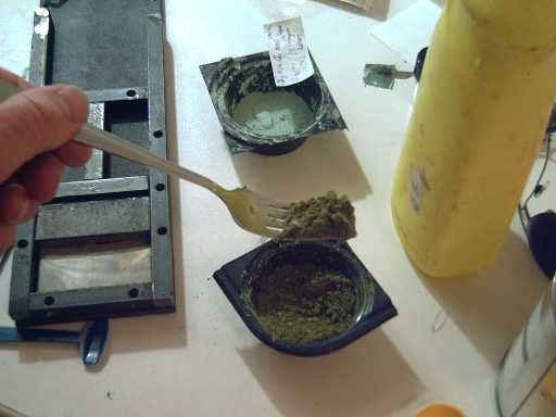
Nickel hydroxide electrode mix for Ni-Mn: surely a "green" battery formula
I only put about 2/3 of the mix onto the plate in the press. I did up the bolts as tightly as possible, just the six near that end of the press. The electrode compacted from 8 or 10 mm to a 3 mm thick briquette. The things weren't very well mixed for all my efforts - splotches of potassium chlorochromate were apparent here and there. Evidently I need a "kneading machine" (being unwilling to stick my hands in there, especially with the potassium chlorochromate). The electrode was still fairly dry, except around the edges, where it appeared saturated, and there were actual drops of yellowish liquid under the plate.

Next I dripped ethanol (AKA Alberta "triple distilled" vodka) onto it and wetted the whole surface. Then I steamed it for a couple of minutes in a pot on the stove. The wet heat activates the agar, and creates acetaldehyde between the chlorochromate and the ethanol. The electrode rose a bit, somewhat like a sponge. That's probably okay - the battery book says positive nickel electrodes swell.
Then I dripped on HCl and wetted the whole surface with that. The acid changes the acetaldehyde into an acetal ester monomer, which then polymerizes (using dishsoap ingredients) to make a plasticy filling to help glue the electrode together. ...Or so goes my rather tenuous theory.
The electrode changed color back to turquoise. Under a 10x magnifying glass it appeared to be well gelled. The impression is of a dense sponge, which consistency is to be expected with the gums. One corner curled up a bit and lifted away from the mesh, but most of it was embedded.
The best proportions - or even good proportions - of ingredients have yet to be worked out. A considerably less spongy electrode (less gums, maybe less agar) would probably conduct better, or else it needs more monel.

Steamed/gelled nickel electrode
Finally, I put the electrode in a tray with some 3% NaClO (bleach) to oxidize it to NiOOH, in hopes of starting with the battery at least partly charged, which may help establish the chemistry. Questions are whether it'll be beta or gamma, and whether it will work at all without adding also NaOH. However, unlike with previous electrodes, it looks like I'll be able to rinse the bleach out of this one without washing away material.
(Well, the rinsing did wash away some material, though not very much.) The color changed from turquoise to blackish (hmm, no picture). That probably indicates success - and that evidently NiO(OH) isn't the turquoise color of Ni(OH)2.
In the last electrode set I made, I noticed that part of the stainless steel mesh had corroded away. I thought steels were impervious to alkali, but evidently the anodic action in KOH is too corrosive even for stainless. It would seem I should buy nickel mesh for (at least) the positive electrodes, which is unfortunately pricey and much more so as it's not available in Victoria and will probably have to be imported. Unless of course I can make the salt-based battery as I hope to do, in which case the stainless mesh, and also the nickel-silver, *might* not corrode.
Then I made the manganese electrode.
I used: 6g Mn powder, 3g MnO2, 0.1g Sb4O6, 0.9g KClCrO3, 1g veegum, 1g CMC gum, (0.5g agar), 1.2g Sunlight, and 3g water. The 3g of water was too much: the mix seemed only damp, but on compaction, yellow liquid was oozing out and puddling on the table. I'll try half that next time.
After compacting the electrode, to about 2mm thickness, I realized I'd forgotten the agar. Scraping the mix off the electrode screen wasn't easy - it was well stuck down and came up in slices with a knife. It also filled the mixing dish much lower than before.


Accidental reaction!

Rinsing it off - wonder what's floating away?
Now if I've charged the positive electrode, as intended and as it appears, and accidentally discharged the negative, the whole thing, in theory, shouldn't work! If it doesn't, I'll use H2O2 to discharge the positive and try again, having no way to recharge the negative.
I put both electrodes in water, which I repeatedly changed until the yellow color from dissolving chlorochromate was much reduced.
The texture of the negative electrode is reminiscent of a piece of rough sponge rubber, although bits break off rather easily. The positive is more brittle and it lost quite a few bits before it made it into the battery. Charging the battery should solidify them - I think.

Mn electrode
The separator sheet was:
- a layer of Arches heavy watercolor paper nest to the manganese electrode. The side facing the electrode was painted with zirconium silicate (ion shield for the manganese), and the other side with ferric oxide.
- The negative electrode with said paper was wrapped with two layers of cellophane.
- The nickel electrode was faced with a piece of watercolor paper and then another piece of cellophane.
Rather than immersion, it was put together as a dry cell.
It doesn't seem to want to charge, like all my other batteries except the one Ni-Fe one I made as an alkaline wet cell 'pocket battery'. I REALLY have to figure out why this is happening, or in spite of all else, I'm not making batteries!
Next I'll try some other ingredients in the electrolyte. Copper chloride will be first.
Another thing to try is to make a gelled separator with agar (& the gums?) to create a "salt bridge". Something I read recently about agar says it's used for this purpose, and a salt bridge is something I've wanted to try all along without knowing how to do one. This leads us straight into the next section on membranes, written earlier...
Now that I finally have working cellophane, I probably have a decent microporous electrode separator sheet, in conjunction with the watercolor paper, for alkaline batteries. But it will last longer if the side next to the positive electrode is protected against oxidation. Separator failure is the main cause of failure of small alkaline batteries. (Hence the longevity and popularity of pocket electrode batteries without separator sheets.)
Plus of course, I would really prefer to make batteries with safer salt electrolyte rather than strongly acidic or alkaline chemistry.
It's quite possible that since the discharge reaction product of salt batteries at the negative electrode is a chloride, and since most chlorides are soluble in water, to have a rechargeable salt battery requires the separator sheet to be a semipermeable membrane that won't allow the dissolved metal ions to pass across to the other electrode. That, of course, would be on top of the zirconium ion shield and gelling the electrode.
The manganese metal powder (and more monel) arrived on the 9th. I'm getting quite excited about using manganese - electrochemically it looks just about perfect for a negative alkaline electrode, and it's quite conductive. Barring some unexpected problem (the dendrite growths that have plagued zinc electrodes come to mind), it is surely the best element for the purpose on the whole periodic table! It's almost as good in salt solution - the reaction voltage is lower but still higher than most.
I sort of wonder how I missed it earlier. And why did no one else spot it in the past? Well, the many reactions and valences of manganese are sort of overwhelming. I've looked at it before and missed seeing that the best one on the far right wouldn't do anything weird, at least if the battery is positive limited - the usual case - and not driven into reverse charge. (Even then, it's probably reversible.)
Mn(OH)2 + 2e- <==> Mn + 2OH- [-1.56 volts in alkaline solution, probably about -1.2 in salt] And, manganese oxides seem to be very conductive as oxides go.
MnO2 (Mn valence IV) is the standard grocery store dry cell and alkaline dry cell positive electrode material (discharging to MnO(OH) - III), and a lower oxide (Mn(OH)2 - II) should be substantially more conductive. Unless there is a hidden problem, it should make for excellent cells with inherently high current capacity, about 2 volts for Ni-Mn in either alkali or salt.
Tabulating the 'rare earth' elements discloses that praseodymium and terbium could make good alkaline battery positive electrode chemicals.
In alkali, XxO2 dioxide (or XxO(OH)2, oxyhydroxide) <==> Xx(OH)3, valence IV to III:
La +? - No valence IV energy listed, but "lanthanum oxyhydroxide" exists.
Ce -0.7 volts
Pr +0.8
Ne +2.5
Pm, Sm, Eu, Gd - no valence IV listed.
Tb +0.9
Dy +3.5
Ho, Er, Th, Yb, Lu - no valence IV listed.
Pr(OH)3 + OH- <==> PrO2 + 2H2O + e- [+0.8V]
Tb(OH)3 + OH- <==> TbO2 + 2H2O + e- [+0.9V]
Those are better voltage than NiO(OH)<==>Ni(OH)2 [+0.5 volts] and might be fairly good alternatives to it. On the other hand, these are likely to be moderately pricey elements, the molecular weights are higher, and the electrical conductivity remains to be determined. If the conductivity is higher, that would be a good point in their favor. I still haven't determined for sure that lanthanum oxy-hydroxide (which has been mentioned on the web but isn't in the regular tables) has a workable voltage as I suspect. Lanthanum is considerably more common than praseodymium or terbium.
La(OH)3 + OH- <==> LaO2 + 2H2O + e- [around +1.0V or a bit more in alkali and +1.5V in neutral salt solution is my guess - and hope. That would make La-Mn cells around 2.45 volts nominal. Pr-Mn: 2.25V, Tb-Mn: 2.35V.]
molecule weight
Ni(OH)2 (59+34) = 93; NiOOH = 92
La(OH)3 (139+51) = 190; LaO2 = 171
Pr(OH)3 (141+51) = 192; PrO2 = 173
Tb(OH)3 (159+ 51) = 210; TbO2 = 191
Owing to the molecules being about twice as heavy, hence having half the amp-hours per kilogram, any of these will have to have over twice the voltage of nickel to improve the energy density. Or, they need to be denser by enough to shrink the size of the electrode and hence the battery, which would reduce the weight of the monel needed to get good conductivity and of the case and electrolyte. Since Ni(OH)2 is very fluffy, it isn't impossible one or more of these elements could be better overall. (Or, they need to charge to valence five and move two electrons per molecule, eg, LaOO(OH), which idea I have little confidence in as I've never seen it mentioned for any of them.)
All October's new battery design work was in the early part of the month. Then the letter, lead-acid battery tests and the magnetic torque converter took precedence.
Finally, here's what people who get funding get for testing individual electrodes so they can see what's working out and what isn't:

The Lead-Acid Battery Renewal Project:
Progress Report

Project Overview
On August 31st I heard some people had been renewing lead-acid batteries by replacing the electrolyte with alum (sodium aluminum sulfate). A short web search revealed that it was also being done by adding epsom salt (magnesium sulfate) to the existing electrolyte. Since the batteries normally work with sulfuric acid ("hydrogen sulfate"), these related salts seemed to make some sort of chemical sense and I decided to check it out.
First I should dispel a couple of fallacies: Some people wrote that their scrapped battery seemed to perform "better than new" after being restored. This appears unfounded - but "like new" is probably attainable. It should also be noted that some were saying that the electrolyte was now "safe" because it was salt solution instead of acid, but in fact whatever sulfate salt is put into the battery quickly forms sulfuric acid and the pH drops to 1 (strong acid).
I determined that both alum and epsom salts would leave solid precipitates - sludge - in the bottom of the battery, but that Glauber's salt (sodium sulfate) wouldn't: it's the "correct" salt. I also discovered that the pH of the electrolyte quickly goes to 1, strong acid, regardless of what is used or added.
So after several weeks of playing around and experimenting, I found the right salt, have the essence of the renewing action figured out (more or less), have written practical instructions for treating or renewing a battery, and obtained some illustrative test results. These findings and renewal instructions are below.
Sodium sulfate salt appears to solve the main problem of lead-acid batteries: gradual passivation of the electrode surfaces by non-conductive lead sulfate build-up. It appears to dissolve this corroded layer. Instead of ever decreasing performance, lead-acid batteries should continue to give "like new" service for long periods.
Claims by enthusiasts of alum and epsom salt that restored batteries seemed to perform "better than new" appear to be unfounded, but I confidently expect that the life span of lead-acid batteries will be more than doubled with sodium sulfate salt - perhaps tripled or quadrupled, allowing them to provide many years of "like new" service in all applications - and that they will suffer considerably less damage from overdischarge, or from being left for a while in an uncharged condition, than has been the case until now.
Now for me, the time has come to quit this detailed experimenting and just use it. (I do have other things to do!) I'm putting some sodium sulfate salt (as sodium hydroxide) in my car battery and in the three big "deep cycle" batteries I've been using to test the Electric Hubcap motors, though they have been so far in good shape. (The car battery is near new, the previous one having been recycled a few months ago.)
I've changed my car battery to the Panasonic in "Experiment 1". The next test on it will be after I've used it there for a couple of months, to see if there's been any "long term" improvement with the salt in it in actual use. Then, similar "long term" tests with the batteries for the electric motor once I have the car running with it.
The main killer of lead-acid batteries is buildup of corrosion on the electrode plates.
It is commonly said that this is a build-up of lead sulfate. I first conceived that it must build up to a thickness or consistency where the surface of the electrode is no longer in electronic contact with the electrode's connections - the good layer is shielded from the electrolyte by the bad. This "passivates" the "sulfated" portion of the electrode. Passivated portions, can't charge up to eliminate the corrosion and renew themselves any more, and the useful portion of the battery plates keeps shrinking.
But on considering the problem and the solution, it seems likely to me that the main problem may be a build-up of lead oxides - corrosion. The positive plate is supposed to have lead oxide, but the negative plate is supposed to be metallic lead. When the corroded, oxidized negative electrode is charged, it charges only from the oxide to the sulfate ("sulfation") instead of from the sulfate to the metal, while the positive plate has finished charging and the battery will charge no further. The battery gradually becomes more and more out of balance as the lead corrodes.
By solving this main problem, these batteries will last far longer, and will perform well for most of their life rather than continually deteriorating.
When the sodium hydroxide or sodium sulfate is put into the cells, a couple of visible things happen. First, they percolate - obviously the immediate cleaning action - and sometimes the gas (sulfur dioxide) may be seen coming out the hole. Second, the electrolyte turns from clear liquid into dark brownish, sludgy looking liquid. This color gradually clears, the lead sludge probably sinking to the bottom of the case. It appears to form clumps, so it probably won't move once it's settled.
An invisible thing happens too: the specific gravity of the electrolyte drops a little, eg from 1.250 to 1.225. Evidently the battery is discharged some in the process. It seems to come back up after recharging.
Here is my basic take on what's happening: The motive cleaning factor is that the voltage of the PbO2 to PbSO4 reaction is 1.68 volts in acid, however, in neutral solution, it would be over the 2 volt limit for aqueous solutions, and the lead dioxide will discharge spontaneously to lead sulfate. Adding a salt puts neutral factors into the solution and the oxide starts discharging. Even if oxide on the positive plates is discharged, the overall effect of reduction of oxides brings the battery back into balance so it can be fully charged (and the pH lowers to 1).
But I don't have it all figured out. The brownish color is probably some form of lead oxide (there are several types) or lead sulfate, a powder that has come off the plates, and the gas is part of the same reaction. For example: PbSO4 (plate sulfation) ==> PbO2 (powder) + SO2 (gas). I'm not sure how the interactions would work to cause such a reaction. There may well be lower oxides involved in oxidized plates: PbO, Pb2O3, Pb11O15... or conceivably higher oxidized sulfations: PbOSO4, Pb(SO4)2 (which may or may not exist but if they do may well be insulators and hence can't be electrically discharged). I'll leave it for some chemist who may someday get paid to figure out exactly how and why it works.
The presence of the salt appears to have a lasting residual beneficial cleaning action.
In September I was under the illusion that the pH of the electrolyte could possibly be raised, which might yield a higher battery voltage. Owing to this, in most of the batteries I was putting extra sodium in some cells trying to get the pH and voltage to rise. This made for delay and poor test conditions for simple battery renewal, and used up my batteries, leaving them in unknown conditions for trying to record improvements.
I wrote of one battery that at the end of the month was taken from a non functional state with an internal bad connection (presumably corroded) to a working condition. But it still had very little energy available.
In October another experiment was performed on a newly acquired battery with some performance figures noted, and I did some practical renewal of batteries that were in actual use, some on what would normally have been their last legs. I had planned to do at least two well documented battery renewal experiments, but the first one took up considerable time and I didn't have the stomach for doing it again.
First experiment: A scrapped medium size (about 33 pounds wet) "Panasonic" car starter battery was load tested, then treated, then retested, then re-treated, then retested again over about 3 days. Ongoing load tests continued for several more days to determine any gradual or residual changes. No performance specs were printed on the battery. Discharge Rate in all tests was very close to 10 amps (4 car headlights: Actual data: at 11.2V they drew 9.8A; 11.6V - 9.9A; 12.8V - 10.5A). Charging was limited to 8 amps by a "smart charger" that reduced the current as the battery came up and ended with a small continuing float charge. Load tests were terminated when the voltage dropped to 11.00 volts. As the voltage dropped it dropped progressively faster, and discharge to, eg, 10.5 volts would only have added another minute or two to the times - even just seconds in the first two tests. I wrote down exact time and voltage figures, but the main results are the interesting thing.
Two discharges on the untreated battery gave the following results:
Test 1: In 12 minutes and 30 seconds (12'30") the battery discharged to 11.00 volts
Test 2: It discharged in 12' 30" to 11.50 volts
For the greater part of both tests, the voltage stayed near 12 volts, then it started dropping rapidly. I accidentally stopped the 2nd test 1/2 volt higher than the others, but the voltage was dropping so fast by 11.5 volts that it would been down to 11.0 in another minute or so. These tests indicate about 2 amp hours were available (above 11 volts) at this discharge rate. The battery recovered to over 12.5 volts both times, indicating it had only used around half of its stored energy owing to poor operational conductivity. (With a slower discharge rate, eg one headlight, it might well have given more amp hours overall.)
The treatment was 60 cc/cell of s.g. 1.30 sodium hydroxide solution. This was squirted in the vent holes with a syringe, and mixed by sucking and squirting the fluid with a hydrometer to circulate it.
Gas could be seen emitting for a short time, mostly visible while the NaOH was being squirted in. The cells percolated vigorously for a minute or two. The electrolyte turned a dark brown, almost opaque. This gradually cleared up.
(I wore a face shield but only one rubber glove. I thought I was keeping my other hand well away but later I noticed a finger was sore and I found a small hole through my skin by a knuckle, doubtless made by a small unnoticed stray drop of splattered acid or caustic soda. Without the face shield it could have been my eye! A nice pair of pants has three small holes in them from previous stray drops that I didn't think could reach there. Here again, you're warned - these are dangerous substances; don't take any foolish chances!)
Test 3: Discharged to 11.00 volts in 23 minutes.
Test 4: 11.00 volts in 24'40".
Battery sat overnight after charging; in AM (Oct 5th) voltage was 12.69 --
Test 5: 11.00 volts in 23'23".
As before, the battery lingered around the 12 volt level for some time, but when it started dropping, below about 11.75 volts, it was more slowly than before so that the running time was about doubled and figures of around 4 AH were attained instead of 2.
The recovery voltages after 5 - 15 minutes were lower (around 12.2 - 12.3), indicating the battery was conducting better - it had been better able to draw on its stored energy and had less remaining.
There seemed to be no further increase in performance over time or charge cycles.
After test 5 I added another 30 cc/cell of NaOH (Oct 6th) to see what effect that might have -- better or worse. There wasn't a lot of bubbling, and there was much less brown in the electrolyte this time. The first time it was almost opaque, this time just a somewhat darkening color to the liquid.
This is no doubt partly because I only added 1/2 as much NaOH, but the great amount of decrease suggests that there was much less lead sulfate remaining on the plates to react with.
Test 6: Dropped to 11.00 Volts in 24'25".
Test 7: 25 minutes even to 11.00.
Test 8: 26'30" to 11.00v.
Test 9: 27'13".
- sat on float charge 36 hours -
Test 10: 29'05".
Evidently adding more salt had no immediate notable effect. But the energy storage after treatment appears to be very gradually increasing with time and-or cycling, a 26% increase by the last test.
The voltage drop at one minute into the load tests increased in tests 3 to 10, the voltage being, eg, 12.03 volts in the first couple of tests to about 11.8 volts by the last ones. Recovery voltage in 5 minutes after turning off the lights progressively decreased from tests 3 to 9: 12.26, 12.22, 12.20, 12.17, 12.14, 12.14 and 12.10 volts. One might attribute these results to gradual deterioration, but that is belied by the gradual increase in running time. And this was a car starting battery, not a "deep cycle" battery. This type is well known to hate being very much discharged and cycled, an operation these tests repeated ten times.
3.8 AH (rising to 4.85 AH by test 10) doesn't seem like much energy. Of course, when one takes batteries off a recycling pile at "Battery Doctor", who themselves reconstitute whatever batteries aren't too far gone for resale, one must expect very questionable batteries. (Two of five I got had leaks!) Questions for further study:
1. Was 60cc/cell already more sodium hydroxide than was needed for restoring this battery?
2. Will the "excess" sodium sulfate remain in solution and cause the battery to remain healthy for an extended period of time?
3. Is it useful to add salt to a new battery?
Perhaps questions 2 and 3 are already tentatively answered by the gradual increase in performance after treatment. There must be some optimum amount to add, though.
I added another 20cc/cell and did more cycle tests. It hit the 1/2 hour mark. I put it in my car. In a month or two I'll bring it back in and see what change there may be in its performance, better or worse.
(I must note that in experiment 5 there was a similar initial doubling of capacity in the third and fourth tests without adding any salt.)
Second Experiment: The next battery that looked like a good test candidate was a Megatron Deep Cycle battery about 7w x 10L x 8t nches, 45 pounds wet. (This was from a different store's scrap bin.)
To my surprise it was 12.6 volts before I even did anything. After charging and then sitting all night, it was still 12.98 volts in the morning. Why then was it in the scrap bin? Answer: reduced capacity.
Test 1 (Oct 10, untreated): Dropped to 11 volts in about 57 minutes. (9.5 AH)
The exact time to 11.00 volts wasn't recorded: at 55' the voltage was 11.46 and dropping increasingly quickly, but I answered the phone and unexpectedly it was way down to 8.5 volts when next read at 60'. Like the Experiment 1 untreated battery it died rapidly once it went under around 11.5 volts.
The treatment was 25 grams of anhydrous sodium sulfate powder poured into the hole of each cell. When I did this, to my chagrin I discovered that the fluid level was way down in all cells and it took over 2 liters of water (400cc/cell) to refill it. The level was probably well below the tops of the plates (the plates can't be seen in this battery.) Unfortunately, this makes the results of the "before" test (test 1) pretty much irrelevant, and the salt was now in the battery.
After the salt treatment and refilling, the S.G. was only around 1.075 - very diluted. (Normal for a charged battery is 1.25.) After charging it went up to 1.16 or so. The next morning it was 1.175 and I did a load test. It stayed near 1.175 even when the battery was discharged.
Test 2: dropped to 11.00 volts in 83'45'. (14.0 AH)
Better, but not very good. I tried it a couple more times with similar results, and then added another 10g salt.
Third Experiment: A friend brought a car battery that wasn't starting his car (not until the very day it wouldn't start), another 33 pound Panasonic battery. I charged it a little while and did a load test at 10 amps. The battery ran above 12 volts for almost 5 minutes, then nose-dived to 11.00 volts, where I shut it off after exactly 5 minutes. It almost immediately recovered to 12-1/2 volts. 15 grams per cell of anhydrous sodium sulfate were added to the electrolyte, which only clouded a bit and bubbled a bit.
I was expecting dark brown and considerable percolation. Seems it's only when you add sodium hydroxide that that happens, and it probably indicates that adding sodium hydroxide straight to the battery is a bad idea.
I recharged the battery at 8 amps until it seemed pretty much charged. This also gave the salt some time to act. Then I ran a second load test. The battery dropped more slowly and didn't "plummet" until below about 11.4 volts, and ran a total of about 17 minutes to 11 volts.
Probably it will continue to improve for a while with use.
I charged it again for 15 minutes at 15 amps until my friend (who had phoned just as the second load test ended) came and took it back to use on his car. I only had it a couple of hours. I asked him for a report in a week, but he brought it back the next day saying it was barely starting the car and he'd bought a new one. It didn't get much chance. I wished I'd been able to charge it more and cycle it a couple of times.
I didn't have time to look at it again for a while, but on the 30th I charged it quite a long time and then did a load test. This time it lasted over 24 minutes, again spending most of that time above 11.5 volts and only a couple of minutes once below 11.25, and it recovered to 12.33 volts in 5 minutes. On the 31st I ran it again and it went 29 minutes.
Fourth Experiment: Trojan T-105s. Somebody gave me two of these huge 6 volt batteries and I hurt my weak back carrying them into the house. The SG of the cells was very low - one or two seemed to be just water. I charged them for a couple of days, and they were still drawing several amps of current. The SG went up to 1.10 to 1.125.
As they were so large, I decided to run tests at 25 amps load instead of 10. The voltage dropped below 11 volts in 45 seconds, but as it dropped the rate of decrease slowed, so I ran them down to 10.5 volts. As the rate of decrease was still slowing, it was evident that they still held considerable charge, but I ended the tests there. In the "before" test, they ran 4'30".
Then I added just 15cc/cell of Na2SO4. That seems like not much for such giant cells, but I think I may be adding too much, so this is an attempt to see how little is effective. The electrolyte was almost clear.
The second test, they lasted for 6'. Better but not much. But if they continue to improve, perhaps it's enough that they will gradually restore? More tests!
The third test they only went 5'.
I dropped the load to 10 amps and they behaved better, but they seem to have lower voltages than most batteries. Running them down to 10.00 volts gives them up to about 2 hours time, or 15 - 20 amp-hours. But they don't seem to be improving much over time, and they glurp and spit out or drool acid that collects on top while they're charging, even with a very low charge rate. I think I'll toss them. The voltages test even between the two, so it's not just one bad cell in one battery.
Fifth Experiment: this is a third Panasonic, which had been sitting unused for some time. This time I did several "before" tests and it showed considerable improvement just from being cycled.
Initially, it didn't stay up to expected voltage, dropping to 12.2V overnight.
"Before" tests (time until voltage dropped to 11.00 volts, in whole minutes): 18, 16, 28, 29, 35, 37, 33.
After these cycles, it held at 12.9 volts overnight.
Evidently, cycling of a battery that's been sitting does considerable good even without the salt.
Then 50cc of sodium sulfate solution, SG 1.25, equivalent to about 12.5 grams of anhydrous salt, was added to each cell. Tests afterwards ran 26 and 29 minutes. Here time ran out - I'll try a few more runs in November.
This experiment wasn't a very positive report for the salt for immediate improvement, and it suggests that some other results may have been positively affected by cycling as well as or instead of by the salt. I still expect it should work well for long term maintenance of condition, instead of the usual gradual deterioration. I'll be putting it in my healthy batteries and monitoring them over the long term... and I'm still using the previously discarded battery from experiment one in my car - almost 3 weeks now.
Using the salt is safer than using sodium hydroxide. I said "15 grams" below, but I'm still not sure what might be an optimum amount to put in. I've tried 15 to 50 grams, and beyond, but somewhere beyond is worse. If 15 grams doesn't seem sufficient, try 30.
1. Buy: face shield (at least eyewear), rubber gloves (grocery), a funnel, and at least 100 grams of anhydrous sodium sulfate salt (compounding pharmacy), preferably more, eg, 500. (You might also find it at a pottery supply, but it may be impure and-or it may be hydrated, in which case double the weight or four times the volume (2.27 (over double the molecular weight) x 2.66/1.46 (density, g/cc) = ) is required.)
2. Don the eyewear and gloves. This is important - the acid is very corrosive, and you don't want holes in your pants, nasty little red sores on your fingers, or much worse to be severely burned or blinded. (I met a virtually blind chemistry professor recently. Familiarity may breed contempt, but it doesn't lessen the danger.) Old clothes you don't care about are an asset.
3. Remove the covers to open the 6 holes in the top of the battery. Set them on the battery, on cardboard or in a plastic container. Be careful not to splatter anything on yourself. The acid will make holes in your pants and-or in your skin. I've taken to putting a piece of cardboard (or a cardboard box) between me and the battery, so only my gloves, old sweater and face shield are subject to little flying droplets. (I've ruined two pairs of pants so far and have had three small painful sores on fingers.)
4. Check the fluid levels in the battery. If any appear low (eg, tops of plates exposed), add pure water (use the funnel?) to top them up. (If you used the funnel, you then need to dry it.)
LEAVE THE COVERS OFF THE CELLS AFTER PUTTING THE SALT IN.
5. Using a measuring device (scale, measuring spoons), for a medium car battery (25 - 35 pounds) measure out somewhere around 15 grams, 15 cc or one tablespoon of sodium sulfate. (That's for the anhydrous salt. Use 30 grams, 4 tablespoons for the decahydrate.) Using the funnel, pour it into the first cell. Repeat 5 more times. Don't lose track of which cells you've done. I feel the salt will all dissolve sooner or later so there's no need to mix or stir it in, which has the additional risk of possibly splashing acid.
6. The cells may "percolate", bubble, weakly or strongly for quite some time, even hours. If the covers are replaced while there is too much percolation, they might pop off, splurting acid all around. This would be hazardous. Some types of covers are screw-on, which is safer, but others simply pop on - and off.
7. Carefully rinse off the gloves, covers, and any equipment or surface that may have got acid on it. When it seems the percolation has died down, or if there isn't much or any, put on the gloves and eyewear and replace the covers.
8. Use the battery.
also see "simplified instructions" immediately above.
1. Get a battery hydrometer (auto supply, eg Canadian Tire), rubber gloves (Grocery) a face shield (Builders Supply) or at least eye protection goggles, and some sodium hydroxide (NaOH, caustic soda - Borden Mercantile gardening etc. supply (in Victoria) or a soap making supply). (I presume you have a lead-acid battery.)
2. There are two alternatives: use sodium sulfate salt directly (drug store or compounding pharmacy) or make it using sodium hydroxide. I'll describe using the hydroxide here for now because it's what I've mostly been doing. The salt is safer to handle -- it's been used as a laxative. But it will only go to around 1.125 density when dissolved unless it's heated up to about 35ºC, at which temperature it's much more soluble.
3. Put on the face shield (or at least eyewear) and rubber gloves. Fill a jar with pure water, not to the brim, and put it in a sink. With a small scoop, slowly add sodium hydroxide powder while stirring. It takes minutes not seconds to dissolve, and during that time it gives off heat. If you add too much too fast, a plastic jar may melt or a glass one shatter, or perhaps the water may boil. The powder and solution (it's also called "caustic soda") is corrosive to skin and will BLIND eyes. When the water clarifies and isn't too hot, you can add more powder. Check with the hydrometer and stop when the specific gravity is about 1.25 or so. I tend to add half, go have a coffee or something, then come back and add the other half.
3. Put the lid tightly on the jar and rinse everything: sink, jar, scoop, gloves, counter. Put away the caustic soda powder.
4. Now to the battery: In addition to face shield and gloves, shield bare skin. Old clothes or coveralls are an asset. Place the battery outdoors or in a sink (bathtub?) where a spill won't do much to anything. (Remember the acid will etch and eat stainless steel if it doesn't get rinsed off.)
5. Siphon acid out of the battery down to the plates with the hydrometer, into a jar. Put the lid on the jar. (What to do with the acid??)
6. Add some sodium hydroxide, an equal amount to each cell. I'm guessing 80cc per cell for a small car battery - maybe a couple of hydrometer fills worth. Keep the liquid level fairly low, not far above the tops of the plates. Leave the top covers off the cells!!! (Otherwise, it might explode, spewing acid!) There will be a strong bubbling, percolating action, bubbling off sulfur dioxide gas. This seems to be the cleansing and renewal of the battery.
7. Charge the the battery, preferably still outdoors. It may bubble furiously the first 2 or 3 charges and the covers may still 'explode' off if they're pushed on - that's dangerous.
8. Do some charges, and discharges down to about 11(?) volts to recondition it. I use a halogen car headlight or two or four for a load - they draw about 3 amps each... and if placed strategically the light will remind you not to accidentally leave the battery running until it's dead again.
At some point the bubbling will be reduced to the point where it is safe to replace the battery covers. It seems no matter how much salt or alkali is added, after the bubbling the battery pH is 1: strong acid. Thus, there's probably a limit to how much sodium sulfate is useful or desirable. Another question is: Does it just act once, or is there an ongoing anti-corrosion or other beneficial (or otherwise) effect?
BTW: If you notice a white powder around the battery holes: if it's long thin "needle" crystals, it's sodium sulfate salt (Na2SO4) formed by the acid (H2SO4) and the hydroxide (NaOH). (The other product of this reaction is H2O) If it's simply powdery it might be NaOH, nasty hydroxide, AKA "caustic soda". (If there's liquid it might be anything.) Whatever... put the covers on the holes after it stops bubbling and hose down the battery.
http://www.turquoiseenergy.com
Victoria BC