Turquoise
Energy Ltd. News #42
Victoria BC
Copyright 2011 Craig Carmichael - August 2nd 2011
http://www.TurquoiseEnergy.com
= http://www.ElectricHubcap.com
= http://www.ElectricWeel.com
Spotlights:
* Advanced "Current Ramp Modulation" Brushless Motor Controller made
and tested
* "Battery Sticks": Stacking dry cells in pipes makes using a
zillion of them for big (EV) batteries more practical.
Month
In Brief
(actually pretty brief this time - lots of pictures)
Electric Hubcap System
* 'Final' version Hubcap
motor: "the kit" parts photo, assembled, runs great
* IR2133 Motor
Controller Works Great (Yay!)
* Advantages of "Current Ramp Modulation" ("CRM") over "Pulse
Width Modulation" ("PWM")
* Finally a great controller (tentatively $499) for a great motor
(kit $499!)
* Regenerative Braking control! (a simple add-on control
circuit)
* Zinc undercoat: spray it on, heat treat it in oven, then spray
paint finish coat over it. Forget powder coating!
Nickel - Metal hydride Battery Project (focus:
Battery Cases)
* NiMH Battery Update: bought a pile of D cells, NiMH
prices, sold a
car battery
* Stressed solder joints fatigue with road bumps & vibration.
* New Case Design: Battery Sticks! load NiMH D
cells into Plastic Tubes. Fast. No soldering.
* Motorbike tests, with new controller... and battery sticks.
* 6V (5 D cells), 10 AH, 1 foot sticks, and 12V (10 D cells), 10
AH, 2 foot sticks: 14-20$ - batteries not included.
Electric Weel Motor Project (Electric Wheel
Motor... Rim Motor...)
Torque Converter Project
LED Lighting Project A little
energy efficient home lighting, anyone?
* The kitchen lights: 20 watts replaces 200.
* LED PVC pipe & mushroom diffuser table lamp (Similar lamps
from me: $95)
* Bedroom: Installed ceiling LED globe or mushroom Lights: Simple
- almost trivial!
* My LED table lamp seems to outshine four Wallmart LED
lightbulbs. (YES!)
DSSC Solar Cell Project
* Overall & Latest Concepts overview... but no actual work.
Turquoise Battery Project (no
report)
Newsletters
Index/Highlights:
http://www.TurquoiseEnergy.com/news/index.html
Construction Manuals and information:
-
Electric Hubcap Motor
- Turquoise Motor Controller
- 36 Volt Electric
Fan-Heater
- Nanocrystalline
reflective rear electrodes to enhance DSSC Solar
Cells
- Simple Spot Welder
for battery
tabs, connections
Products:
- Electric
Hubcap Motor Kits, Parts - Build your own ultra-efficient 5 KW
motor!
- Sodium Sulfate
4x
longevity additive & "worn
out" battery renewal.
- NiMH Dry Cell Car
Batteries (please e-mail me to order batteries)
- NiMH Custom Batteries (EVs, E-Bikes, Scooters, etc. - eg, 10 AH
36V $275)
- NiMH individual Dry Cells (D - 10 AH, $10 -- AA - 2.5 AH, $2.50)
- Motor Building
Workshops
...all at: http://www.TurquoiseEnergy.com/
July in Brief
July saw valuable new ideas for easily making large dry
cell
batteries and LED lights, and important electric drive components
finally
starting to come together.
I finally assembled an Electric Hubcap motor in
the planned 'production kit' form, and ran it with the newly designed
and made IR2133 motor controller. The motor ran great, but the
controller
still had some "glitches".

The parts of the Electric Hubcap motor kit
(body 'ring' parts were drilled & painted shortly after photo,
coils were redone with ilmenite)
The
motor/controller set is key to moving cars regardless of everything
else, so I then focussed on the controller. It had the very same
troubles with spurious very high currents as previous types. Re-reading
IR's app notes on driving high
power
MOSFETs led to a minor change
to the power MOSFET wiring... which cured the problem! Since then it's
been stable even at the full 42
volts with heavy loading and high stress tests. Evidently nothing more
than unshielded
MOSFET gate wires 2 or 3 inches too long caused much of the grief and
many of the blown MOSFETs and chips over the past couple of years.
But the new IR2133 controller is the best. With it I was
finally able to
verify that regen braking is done
simply by reversing the motor thrust. This causes it
to pump current back into the batteries as it slows down. A simple
add-on circuit tied into the brake pedal will activate this process.
At last I seem to
have a fine
controller, with the superior "current ramp modulation" and regen
braking, to go with the
fine motors!

'Production kit' version Electric Hubcap motor

Motor controller with IR2133 as controller chip.
Longer gate wires became twisted pairs for shielding.
Other things inevitably got neglected. The promising
[Mn/Ni]-Ni battery went untouched, as did the torque
converter.
I did do some work on the Weel motor: I put
the polypropylene-epoxy skin on the stator parts, painted the metal
center, and entered drill co-ordinates for the CNC machine. For 162
hole positions, I finally thought to use a spreadsheet to generate the
numbers instead of a hand calculator, making what would have been a
very tedious job manageable, and I got the holes drilled.
And with a dozen bright Cree XM-L-H LED emitters, I did a
few more LED house lights. And I've ordered some
more LEDs and components - this time a greater variety to try out, and
some LED drivers -
thinking also of how much fuel LED lights could save in gas cars, and
the increase in range (however slight) for electric vehicles. After
mid-month, I realized I was turning on LED house lights without even
thinking about it. I was already used to the whiteness of the light and
it seemed normal. This played some small part in getting my lowest
electric bill in decades.

Kitchen Counter Hanging Globe


2 Emitter PVC Pipe Mushroom Diffuser Table Lamp

Bedroom Globe at peak of sloped ceiling - 2 emitters pointing down
Unfortunately, no one seems to make receptacles that fit the electrical
boxes used for lights. Instead,
I had to install a light socket and put in a screw-in receptacle for
the power
adapter, after removing an unsuitable old fixture.

Typical LED light circuit
I also got some more NiMH D
cells, "on sale" at the lowest
price yet - 365 US$/KWH list. I made and sold a NiMH car battery
($275),
and I now have
250 cells available - 3 KWH - enough for
35-40 Km range with only 100 pounds of weight and for about $1500.
Unfortunately, prices (no doubt for all batteries) went up
substantially before the end of the
month, D cells (in quantity) suddenly going from about $5.80 list to
$7.20.
(A bit of a shock.) I
also note supermagnets have tripled in price and more since February.
Seems I got my supplies at the right time, and I wish I'd bought more
of everything! These things are made in China. It would seem western
society really needs to tear down
the barriers erected by corrupt vested interests to making such hi-tech
things here,
and start learning how to produce our own.

12V NiMH battery in Honda Insight
I took the
battery out of my car and checked it. On the bottom side, some solder
joints had
come loose. The weight of nearby cells was stressing some of the
joins apart on road
bumps.
I'm now trying out an entirely different construction,
putting them end to end into tubes such as 5 cells (6 volts) or 10
cells (12 volts), with tube ends that press them together for good
contact, and links between tubes. That seems to eliminate all the
problems... and the soldering... to make for cheap, reliable car
batteries. Any number of small cells are now easily employed to build
huge (EV) batteries.
And I can just sell cases and let people find their own D cells
(or AA or C?) to fill them with.


And, I wrote up my latest
thoughts on a design of DSSC
solar cells using the borosilicate glaze/glass with nanocrystalline
titanium oxide that I developed. If I have no time to work on it,
perhaps it can
at least point directions for future experiments, by me or others.
There
would be no
expensive ingredients in these solar cells, so they could potentially
become 'dirt
cheap' and solve a lot of clean power generation problems.
Electric Hubcap Motor System
Electric Hubcap motor - kit version, parts, assembly
I could have put a
motor together fastest in one of the
three first, larger diameter cases - two of them are ready to use
except for paint and
some hole drilling. But I wanted to do one in the new production size
case -- the first one to be done just as I wanted to sell as kits.
I made the first
flat plate magnet rotor in June. Now
I made the outer edge cover of the rotor compartment. I wrapped a
couple of winds of 2" PP strapping around the rotor end cover and
epoxied it, using the UHMW polyethylene disks from the molds to hold
the shape and diameter. After it set, I wrapped and epoxied a couple
more winds of
1.5" strapping on the inside. This gave a rotor outside edge almost
1/4" thick, with a flat to set the center ring/cover on and a lip
around the
edge to hold it centered. (It would have been more ideal if it made the
rotor compartment
about 1/8" or so wider. But I can't seem to find 1-5/8" and 2-1/8"
strapping.)
The $500 Electric Hubcap motor kit: all the parts spread out on the
workbench.
(Magnet rotor without magnets is shown - supermagnets and epoxy for the
rotor aren't supplied with the kit.)
At the time of this image, the body pieces still needed painting and
their holes drilled.
The coils were a reused set, from a recently disassembled motor.
From Top-Left: Magnet sensor board on inner ring, rotor
compartment cover with bearing holder & bearing,
1" axle/shaft with SDS taper-lock shaft bushing to hold magnet rotor,
plastic bug
screen, 2" wide PP strapping to hold magnets, magnet rotor,
some spacers, APP power plug housing, coils & bolts, outer stator
ring, bearing holder pieces with spacer, bearing & bearing 'cup'.
Next I spray painted the PP-epoxy parts with Dolph's
polyurethane insulating spray paint (color choice: brick red only -
source: Troy Electric motor shop) to make the surfaces heat resistant.
Then I put the bearing and bearing/planetary gear holding plate
on the
rotor side, and assembled the axle (the one set up for attaching the
sun gear) and rotor.
Next day (12th) I fired up the CNC machine and drilled the
stator holes in both pieces, and in the ones for the three larger
diameter motor cases as well.
I also took the 'used' coils apart and
dissolved off the rutile/sodium silicate, which didn't work as well as
ilmenite does. I found some of the sodium silicate seemed to have
become insoluble all by itself and there were a few sections I couldn't
get off. Perhaps if it's left dry long enough, it will all gradually
become permanent. Then I spent time sanding the coils, hoping the
ilmenite would stick better and not flake off. (It didn't seem to help.)
On the 16th I spent some hours trying to get washers for
the coil bolts. The ones I had were too thin, and when tightened turned
dish shaped instead of spreading the force. I had tried before in
passing to get some, but Rona and Capital Iron both had only the thin
ones. I knew where I wanted to go: Fastener Force. But it was Saturday.
I would have had to wait until Monday. I finally found some thicker
'metric' washers at Canadian Tire View Royal. At the end of the day I
finally had the motor together.
The next day I tried to run it out at the car. It ran, but
it didn't seem I had the phases connected right. (There are two "wrong"
ways out of six where it seems to run but draws way more current going
one way than the other, three where it won't run, and one right way. I
haven't found a system... yet... to figure them out on a new motor
besides trying them out.) While swapping wires around, the controller
made some alarming noises a couple of times, and the currents shot way
up. Then on one try it blew. Sigh!
Finished Motor, 32 pounds all up.
(finished except for bug screen - must be a better way to fasten
it than staples!)
The new motor ran
great with the new IR2133 controller on the 18th, though the
controller still had some glitches.
At about 16 volts, I
got
no-load readings of 2.2 amps at a steady 500 RPM (35 watts) and 4.7
amps at 1000 (75 watts). These are fantastic figures for a 5 KW motor!
As an indicator of how far things have come, the earlier Electric
Hubcap
motors used 250-500 watts no-load at 1000 RPM.
Recapping the big improvements:
- the PP-epoxy composite stator rings replaced the metal (disk brake
rotor) plate, reducing
magnetic drag
- the very low loss iron powder coil cores replaced the iron laminate
cores, reducing drag & current
- the ilmenite in sodium silicate coil coating creates a low
magnetic resistance path that bends 'wasted' lines of magnetic flux
around into the core, providing more flux with the same electrical
current. This innovation of mine gives it an edge over every other
motor.
IR2133 Motor Controller
After it gradually
dawned on me that low low-speed torque from the MC33033 controllers
was a big
part of the reason the car wouldn't move regardless of mechanical
designs, and after all the failures of
the
A3938 controllers I'd been trying to make since last fall, I designed a
new one around the IR2133 chip -- taking
the design back almost to 2008 when I actually got the car to move with
the IR2130 controller, but with important improvements, especially
including the variable frequency 'current ramp modulation' ("CRM", with
its
implicit overcurrent protection), and needing
only
two
chips instead of four or five.
The
IR2133 can be used as an
advanced single chip brushless motor controller. I used certain signals
and
features in (surely) unexpected ways to achieve that, not as suggested
or
implied in the datasheets, and along with the missing forward/reverse
function - one missing pin requiring a whole second chip to replace - I
have little
doubt that the maker, International Rectifier, has no inkling that it
can be so used.
The variable frequency CRM
does three things that PWM doesn't:
* From motor start and at low RPMs current ramps up quickly and the
peak allowed current is rapidly reached. With PWM when the peak current
is reached, the rest of the fixed frequency cycle is "shut off" to
prevent overcurrent, and there's no more torque until whenever the next
PWM cycle begins. With CRM The motor is only shut off for a short fixed
off period (lower 10s of microseconds), then the next cycle commences,
so (unless the PWM frequency is set high) the average current is much
higher.
* As the motor speeds up, it takes longer for the current to rise
(owing to back EMF - generated voltage - reducing the effective voltage
to the motor.) A fast switching fixed frequency PWM is then wasting
energy and making heat in the controller with unnecessary switching.
The CRM frequency will naturally drop as the current takes longer to
rise to the setpoint.
* Current lags voltage in an inductor (a motor is an inductive load),
so using current control instead of voltage control also helps correct
the phase angle of the current with respect to the actual positions of
the magnets, again improving torque. When the commutation switches as
the magnets rotate, the very first modulation stays ON until it brings
the new set of coils up to the selected current and torque using the
full available voltage. Only a control that anticipates changes of
commutation, or magnet sensors advanced from the switching mid-points,
can improve on this timing... and such measures are pretty much
academic at the Hubcap motor's speeds. CRM is simple and effective.
Sometimes I've wondered why I was bothering with my
own
design when there are
commercial controllers out there. I guess it was the lure of
potentially coming up with something better - or simpler to make - than
what exists. I think the layout is
excellent, and the "CRM" will prove better than
"PWM", which is what other controllers are probably
using.
Certainly the Electric Hubcap motors have turned out to be
exceptional, and people certainly were asking,
"Why are you bothering? There's lots of motors around." And a year ago
my only real answers were "To get that 'pancake' shape, and an easy to
build motor."
On the other
hand, after 3 years until this month I was still struggling to come up
with a controller
that really worked well at all. Certainly I - an experienced (if
somewhat dated in practice) computer and interface circuits designer -
didn't quickly understand the rigorous requirements of every detail in
multi-kilowatt power switching control circuits. I suppose while I was
grasping the basics, I glossed over some finer points in my mind -
particularly the need for short gate drive wires, and the need for
driver chips to be able to handle heavy voltage spikes in the phase
sense lines without damage.
Near the start
of the month I polished up the circuit design and board layout as best
I could think of, and
e-mailed it off to APCircuits[.com] to get the boards made.
Then I ordered the actual IR2133s and a few other parts, and was happy
to think of setting it aside for a while. The parts
arrived within 24 hours of hitting "purchase" on the Digikey.com web
site! The boards arrived the following day. No rest for the wicked! In
another day I had put the
controller together.
Motor controller with the new IR2133 two-chip controller board
But I
got my respite. I wanted to try it on a motor in the shop under
controlled
conditions, and for that I needed to put together another motor
(above). And I wanted it to be a
'final version' motor. I didn't have it
together until the evening of the 16th.
On the 17th I tried the new motor on the car's MC33033
controller. The
motor ran, but while trying to get the phases the right way around,
that controller blew, too! Now the only controller that might work
(without repair) was the new one.
In the new controller (new IR2133 PCB replacing the
MC33033 PCB) I found four blown mosfets before
even starting. No doubt a legacy of the last try on the motorbike. When
that was fixed, I found a solder blob short on the circuit board (power
to ground), and
then a
resistor that hadn't been soldered on one end. My eyes aren't
what they used to be. I did inspect the board as carefully as I
could when I assembled it, using a magnifying glass.
Before connecting
the power leeds to
the motor I checked all the voltages and signals I could think of -
uncovering a wrong value resistor and a couple of
things that needed changing.
I found that
although the datasheets said the 10 to 20 volt IR2133 inputs could
handle logic voltages "as low as 2.5 volts", it seemed they couldn't
handle any higher
than 5 volts! Higher voltages were dragged down to 5.6V. They might
have mentioned that! Admittedly there was a
clue in the "recommended operating conditions" being 5 volts max, but
"absolute max" said 15V. I did wonder why it wasn't 20 or 25V like the
rest of the chip. Had I been more cautious, I'd have e-mailed IR
tech support for clarification. I designed
the whole board around 12 volts. Now it seemed some things would have
to be
redone and a 5 volt supply added for no other reason than to satisfy
this silly
5V logic input voltage limit on a 20 volt chip. For now, I would simply
bend up
the output pins on the CMOS XOR gate and put in diodes in series to
make the gates "open drain", and allow the IR2133 to drag pull-up
resistors
down to 5.6V. That meant unsoldering the 4070. I had
socketed the IR2133 (yay for socketable DIP chips!), but not the 4070,
which seemed unlikely to blow. I
didn't have the stomach for it that day, so I made an LED light for my
bedroom -- something that was highly likely to (and did) work without
any special
trouble.
When I did connect the motor, it was through three .47 ohm
resistors. Once I had the phases right, it ran! The current ramp
modulation seemed to work great, the signals oscillating more or less
as they
should! After a few more tests, I couldn't see anything amiss or think
of anything else to do. I very reluctantly removed the
resistors before they got fried. After all the A3938 failures, I could
just see the IR2133 now going up in smoke the same way, inevitably
taking out a few mosfets with it. It didn't. Hurrah for International
Rectifier's great high voltage MOS driver chips!
After all the troubles, I was cautiously
optimistic that this controller would work well and reliably. But 16
volts
wasn't 36 or 42, and 22 max amps DC wasn't 127. So I went through a
checklist sequence:
Checklist:
- check and decrease 'short fixed off period' with smaller capacitor -
it's long
- view the currents on the scope and see what the real instantaneous
MAX current is
- try higher voltages: 24, 36, 42 volts
- permit higher currents to the desired max...
then (if all is still going well)
- try the motorbike!
Results:
- Off period is variable and short enough as is. (I wish there was some
way to add a little hysteresis to the switching - that should probably
give more uniform results.)
- looked like there were very short transient pulses uniformly of 100
or so
amps - these were no doubt
transient switching spikes. It looked like currents might be increasing
as the control was turned up - or did high currents simply get more
frequent? There was lots of hard to figure stuff on
the scope, including what looked like some RF oscillation. The
oscillation
could be seen simply by having the scope probe near the
controller with the motor running. Nothing looked really neat and
clean... except maybe the motor coil signals. I think a
recording/graphing scope would be useful.
- 24 (actually 27) volts: 40 amps, works fine
- 29 (32) volts: 45 amps, works fine
- 36 (40) volts: worked for a while, but there were some very high
currents with the
control pot turned up even part way. I saw the meter say "150 amps" and
then it
malfunctioned.
Here again, the higher voltage caused problems and major
current spikes. This time nothing blew up (luck?) - it just quit
working. It
seemed one(?) phase still worked but not the other(s), and the motor
came to a stop. When depowered
and repowered at 24 volts, it worked fine again. Seemed suspiciously
like CMOS latch-up. Prime suspect: 4070 CMOS XOR gate, even though it
shouldn't be getting anything but simple logic voltages. On the other
hand, its signals come from the hall sensors in the motor, near
the coils. In the last controller design, I had put in some
filtering... this one I didn't bother.
Another possibility was that the power mosfet maximum
voltage had been transiently exceeded and caused some sort of latch-up.
The IRFP3260s are rated for 60 volts - should I switch to 70 volt rated
IRFP3207s? That seemed less likely, though.
But on going over more of IR's AN978 application note, I
became more impressed with the need to keep all the connections short
and straight. It said "gate connections 2 inches max" - a figure I'd
long since forgotten if I even noticed it on first reading. If it's
longer,
it's an antenna. But the mosfets need to be
spread out on a heatsink for cooling. Even the driver chip itself is
1.6
inches long. This
requirement is impossible. But evidently twisted pair gate wires can
help for longer runs - the twisted pair gives common mode rejection of
induced voltages.
Evidently also, negative turn-off spikes on the mosfet
source
leeds (as well as other induced voltages) can cause the gate to become
positive compared to the source, spuriously turning the mosfet on at
the wrong time.
Spurious switching would explain much of the trouble I've
had. I
decided to shorten the gate leeds if possible, and to run twisted pair
gate wires as recommended in AN978 to all the gates. Not much I could
do about the length of traces on the circuit board, or about having the
mosfets spread out for good heat dissipation, which is just as
necessary.
-
There seemed little need to increase current limiting. If it was to
be increased, I would increase it by upping the voltage to the control
pot and having higher voltages with more noise immunity, rather than by
reducing the 'sense resistor'.
In fact, I might allow 3mV per amp with a 3 mΩ sense
resistor, and set the pot voltage to 381mV for 127 amps instead of
127mV. The noise immunity on
the current sensing should be better. But that sense resistor - 4" of
#8
nickel-brass wire - would get warm if not hot!
Next Steps...
Having similar
runaway current problems at the same voltages as the MC33033 controller
seemed to
indicate that the layout was at least a part of the problem. With the
high currents being switched, every piece of wire must be viewed as an
antenna: an
inductor, capacitor and resistor all at once. My MOSFET layout is set
up not only to keep the transistors apart for heat dissipation, but to
make for short, straight runs on all the high power signals. This is
good, but the gate leeds must reach everywhere.
Evidently the thing to do was to use a twisted pair of
wires, and run the gate
driver to the gate and also the mosfet 'source' signal to the common
return (low side) or to the
phase output (hi side). Any spike on the source is coupled to the gate,
and external
signals are "common mode rejected" - actually coupled to both leeds at
once, canceling the effect at the mosfet.
Consider the spark you get when you touch and remove a 12
volt
battery leed from a coil - it can take a notable chunk out of a
lead-acid battery terminal post. These are the sort of forces the
controller
is dealing with continuously, and it's a miracle any solid state
controller can work at all! I guess it should be no surprise that some
things you wouldn't even think about, like a few inches of skinny
wire, turn out to be quite critical.
I twisted another wire around the longer gate wires
including the 1.5" runs between transistor pairs and soldered them at
the appropriate points, ignoring only a couple of 1" runs to phase "B".
Another problem was the motor sitting there and not even
drawing current when it was supposed to start turning. Flipping the
direction switch and starting the other way usually worked. It seems to
be some problem with not getting
the floating hi-side supply charged, and I had it in 2008 with the
IR2130 too. The one advantage to having the low side transistors stay
on when the high side turns off is that the coils are pulled to ground,
charging the floating high side supply with each modulation. I've
already put in 10KΩ resistors to tug the motor lines towards ground so
the floating supply capacitors charge. So a second mod was to try 1uF
ceramic bootstrap capacitors
instead of .47uF to hold the voltage longer and get the motor to start
turning. Once it's turning, commutation brings each phase to ground
(low driver on), repeatedly charging its high side supply capacitor.
But it has to start turning first...
In IR's app notes, they talk about using "ultra fast recovery diodes".
But then they use some weird numbered diodes that aren't even nearly as
fast as a common 1N4148 fast signal diode. That's puzzled me ever since
I started, but I finally figured it out: they're selecting high voltage
diodes for line voltage motors, and the 1N4148 is only good for 75 or
100 volts. Under about 50 volts, the common 1N4148 is in fact the best
choice.
A third next step was to increase the sense resistor
from 1 milliohm to 3mΩ, making the voltage rise at 127 amps .381 volts
instead of .127. That provides more noise immunity for the current
sense. Thinking a 12"
piece
of copper wire was really long, I used a piece of #8 nickel-brass (aka
"nickel-silver") wire. Measuring the voltage drop with a 1.0 amp
current, it turned out a 4" length was .003 ohms. I didn't immediately
replace the resistor supplying the speed control pot, so the peak
current would be limited for the time being - theoretically - to around
45 amps.
Test...
With these mods, I tried out the motor on the 24th at 17V
and everything went well. It started considerably better - it usually
started turning with no trouble... unless you turned up the control
very gradually and held it back by hand, in which case it would go one
step and then cease drawing current on the next one. Then if you turn
it off a moment and try again, this step works and it stops at the next
one, etc. But the mod has helped. On further trials I found that it
seems unstoppable if you just 'tromp' on the gas a bit instead of
taking it as slowly as possible.
If it proves necessary, I'll increase the capacitance as much as may
prove to be necessary for reliable, high-torque starting. I'm not
convinced further increase from 1uF is really necessary, but ceramic
capacitors up to 2.2uF are under 50¢ at Digikey, so there seems
little reason not to order some and use them.
Success - no spurious currents!
Then I tried it at 24 volts, 29 volts, 36 volts and 42
volts and had no problems. No current readings were seen above about 35
amps. In fact, currents dropped as voltage was increased. At 36 volts I
could hardly catch it above the 20s of amps as the motor gained speed
so fast; at 42 seldom above the teens. That's a far cry from suddenly
seeing 80, 120 or 150 amps 'randomly' flashing by on the meter at the
higher voltages. The twisted pair gate wires seem to have done the
trick.
Further Tests - Higher Currents, Regenerative Braking
I increased the control potentiometer voltage to
theoretically get 100 amps peak current. If I turned the control right
up and then switched the motor on, I saw actual (average) currents up
to about 62 amps with the control turned right up. This suddenly
applied maximum power at maximum voltage is the scariest test to do.
It's where any weak point is most likely to cause everything to blow
up. But everything ran smoothly, and the motor accelerated very quickly.
I also tried reversing the motor from high speed. As I've
suspected all along but never been certain of, the current flows
backwards - into the batteries - as the motor is forcibly decelerated.
Thus, a small external control circuit could enable regenerative
braking:
* If RPM indicates insufficient speed (perhaps under about 15-20 Km/H),
disable the circuit. (This is to prevent the car from trying to go
backwards after stopping.) If the circuit is enabled:
* If "brake" is on (signal from car brake lights), use analog switch to
switch from gas pedal pot to brake pedal pot, and reverse the signal to
the direction switch in the controller.
When the car has slowed enough, the RPM sensor will again
disable this circuit. Note that if your left foot rides on the brake
pedal and presses on it far enough to turn on the brake lights, that
will override the gas pedal and you'll be braking regardless of what
your right foot is doing.
Note: The MC33033 had an
undocumented
"feature" - if the motor was turning the "wrong" way, the low side
MOSFETs shorted it out to bring it to a quick stop. So The IR2133 is
the first controller I've been able to try out regenerative braking on.
On the 29th, after getting not much of a ride on the
motorbike, I reduced the resistor that sets the control potentiometer
top voltage, this time from 39KΩ to 30K, which would theoretically
limit current to the desired maximum, 130 amps. But that limits the peak
current, and the average will be less. At this setting (and 36 volts
supply), I saw currents on the meter (amp clamp) up to 75 amps as the
motor accelerated. I had to remove the motor from the electronics bench
and C-clamp it to a separate table as everything was vibrating off the
bench. I reduced it further to 22KΩ. This time I saw one reading of 103
amps and several in the 90s. The motor accelerates so fast that only
one high current reading flashes by before currents drop off with
speed. I may never be seeing the actual maximum. Then I tried reversing
it while it was accelerating at maximum power, full forward straight to
full reverse. I wouldn't have dared try this with any previous
controller. Everything worked normally - no problems or unexpected
effects. (!) I'll try it out on
the bike before increasing the current further - the currents
might already be hitting 127 amps, which will become visible under
heavier load.
As anticipated, the
current sense
resistor got very warm - almost hot in a short time. I may have to cut
it from .003 Ω to .002 and
drop the sense voltages by 33%. There was little or no heat evident in
the power MOSFET transistors, which are around that same resistance but
the average load is shared by six (x 2 - high and low sides) and they
are mounted on the heatsink.
It certainly appears
I finally have a reliable 5KW
motor controller. Theoretically
the doubled 120 amp MOSFETs can handle 240 amps
continuous, and momentary currents up to 1680 amps(!). I don't plan to
go anywhere near those values - a good safety margin is vital, and the
motor itself would overheat if driven too hard.
"Version 2" will
have a few changes to reduce gate drive runs on
the
board to the very
minimum feasible lengths. Also since 5
volts is needed anyway, I'll replace the 4070
CMOS XOR gate with a 74ALS86, eliminating any chance of CMOS device
latch-up. Other than those points and using a 9 resistor SIP pack to
replace several pullup resistors and save some soldering and board
space (for the 5V supply), it seems good to go.
Ultrasonic Noise
Following the main testing sessions, my tinnitus went
wild, a loud, high-pitched whistling in my ears being clearly evident
especially for a day or two. I had it before recently, too, but was
unable to identify the cause... it was probably when I increased the
frequency of the MC33033 controller. It will probably take weeks to
more or less fade away.
(And I've been so careful lately, wearing ear protection at the
computer and any source of continuing noise, too, trying to get some
peace and quiet back!) The motor coils 'sing' at the modulation
frequency increasingly with the current. There's an audible squeal, but
it doesn't seem very loud. However, paying close attention, I started
to sense at the top of my hearing range that there are very loud
harmonics to this 'innocent' squeal, and I'm sure these loud ultrasonic
sounds - 15, 20, 30... KHz - are ultrasonic earritants.
This is in fact a main reason I chose to use lower PWM frequencies when
I didn't realize it made a difference to operation: If there was
irritating noise, I wanted to hear it and know it was there.
And on a car, a certain amount of sound is actually desirable, as a
warning that something is coming. Only during one of the earlier tests
did I think to
wear hearing protection part way through, since I barely hear
anything... until later.
Fortunately, the motor goes on the outside of the car
(dogs beware!), or under the hood. But if a zillion cars are using high
frequency controllers switching powerful motors, might it be a bit like
car headlights? -- individually okay, but in mass traffic lines, at
times one can
hardy bear to look towards the glare of beams pointed almost straight
in the eyes. Muffling sound is of course possible if it should prove
necessary, but it's easier and the need for it is more obvious if that
sound can be heard.
But perhaps that whole concern is best left to a future
where people have finally overcome the many obstacles and are finally
driving in numbers under electric power! It's probably a good trade
because then the rumbling and bellowing combustion engines will at last
be following the rest of the dinosaurs to extinction.
Metal Parts Coating: Heat
Treating the Zinc and Spray Painting a
Finish Coat
I read a bit more about zinc coatings. It's a good primer
that paint adheres well to, but not a good finish. It also seemed
pretty soft. I heated the finished parts up in an oven to about
225ºC, about
the temperature used when putting it on as a powder coating primer.
That hardened it up considerably, though it could still be scraped off
with a thumbnail.
I spray painted some light beige paint over top of this as
a finish coat. This seemed to work quite well. It's probably as good
as powder coating except for a less perfect looking finish - depending
on the spray paint
used.
Nickel - Metal hydride Battery Project
The NiMH Battery Project is back, this time as an
exploration of the best ways to make NiMH dry cells into batteries
rather than covering electro-chemical aspects. The quality and
potential of the chemistry can now be taken for granted, and the
problem is we want car & EV batteries and we only have AA or D
cells.
A big leap in battery design concept was made: the
elimination of soldering, by stacking cells end to end in tubes with
screw-on ends. It simplifies (almost) everything.
Battery Sale - then a big price
increase
All-battery.com had a "Fourth of July" sale on NiMH "D"
dry cells, and I ordered 140 more of them - 1680 WH. I now have 250 D
cells available - 3 KWH, 95 pounds. That's probably 35 Km or more of
Electric Hubcap travel range, and all 250 at the sale price would have
been
about $1300 to my door. Similar range with lead-acid would weigh about
270-300 pounds, take up much of the
luggage space, cost $700 or more,
and they would hardly last half as long (if!) even with sodium
sulfate
added. (Price isn't counting putting heavier springs in the car's rear
axle.)
I also have about .9 KWH in NiMH AA and 4/3AF cells if I
choose to employ them, for about 3.9 KWH total. But I'll probably stick
to using all identical cells, thought there's no important reason to do
so.
Significant for electric transport, the sale price worked
out to only 367 $/KWH, for the first time under $400. (US$ list price
before shipping, tax, etc.
Lithium types are about 500 $/KWH - straight from Thundersky.com in
China to the battery dealer - and up.) I hoped this sale was part of
the continuing NiMH price reduction trend and would be
repeated
and subceeded. (add to spelling dictionary.) Then NiMH
dry cell battery packs will become ever more
attractive and economic. Lead-acid may gradually become a thing of the
past and
electric transport more economical to purchase.
But near the end of the Month they went up substantially,
from under 6 US$ list to over 7. This probably applies to all batteries
and is part of the price trend of Chinese made products generally.
For range
comparisons: someone reports using around 100 WH/Km in his electric car
(a Canadian Electric Vehicles Suzuki Swift conversion, lithium
batteries). Another
electric car owner (self converted) with lead-acid batteries says he
only has about 20 Km range. But it gets him to work... at an auto
service shop.
I made and sold a battery for a
Honda Insight hybrid, which had (as usual) a lead-acid 12 volt battery
under the hood, that had gone bad. It had to fit in a vertical space,
and I
ended up making a plexiglass case. (an extra pound of weight, but looks
nice!) (I wouldn't be surprised if the unusual shaped lead-acid
replacement battery would have cost as much as or more than the NiMH.)

Ni-MH dry cell battery replaces lead-acid in Honda Insight.
Foam spacers can be seen filling in the empty spaces to keep it from
rattling around.
I also made a new frame to hold the
hexagon pattern I seem to be employing almost exclusively with D cell
batteries, which fits them into a smaller space.

Straight 5 x 6 cells holder for soldering "side 1" (behind)
and hex pattern holder for "side 2" (front).
For electric transport
batteries, I liked the Insight battery's vertical profile. One could
place several side by
side in a small space. I've looked all over the web for appropriate
cases - I can see having to make them. The acrylic is heavier than
necessary and considerable work. PP-epoxy?
All that of course is for new batteries. Cheapest (though
laborious and messy) course is still to scrounge old lead-acid
batteries (or buy
them cheap from a recycler) and renew them with sodium sulfate.
Another interesting NiMH thing I did was order eight 2 AH,
"10C" high rate AA cells. I used them in a new battery pack for the
cordless drill. The original packs were 1 AH high rate ("20C?") NiCd
cells that would put out as much as 20 amps (though that was pretty
much short circuit current). Since NiCd dry cells generally short out
after a while and don't last, the originals packs were long since
kaput. (To get the above specs, I tested an individual cell that was
still working.)
2 AH NiMHs supplying 10C is also 20 amps. Where the drill
had been underpowered with the regular NiMH AA cells I bought at a
store some time ago, these new ones gave it back the power it
originally had and was capable of. The double amp-hours of the NiMH
cells in effect doubles the "C" rating compared to the NiCd cells -
something that might not be readily apparent from a specs sheet. And
the drill battery was lighter and had considerable empty space in it as
the AA cells were smaller than the originals.
For electric drive, these cells would give you the most
power with the least battery on board. But they wouldn't take you very
far. For transport, 10 times as much substance at 1C rate with regular
cells gives lots of power, plus useful range.
Trouble at the Pass
Later, on two occasions I
had a short
dream just as I woke up that my car starter wouldn't turn over. Finally
one day I
took my own car battery out and had a look. On the bottom side, three
of the solder joints had come apart, and two more had weakened and came
apart when I
pulled it out of its case. The weight of the batteries was stressing
some of them on road bumps and they were working loose, and I was lucky
it hadn't stranded me somewhere.
These were soldered
quite solidly when I
made the battery in February - I tugged and twisted the wires with
pliers to make sure they wouldn't come loose - not without redoing the
occasional join.
I repaired the joins and put a piece of 1/2" styrofoam
underneath. This
should deform and help even out the weight. After the repair, the
starter
regained some zip
that said "better than lead-acid", whereas recently it had only seemed
"as good as". The fact that the car continued to start at all with
three disconnects vindicates my paralleling all the cells at every
second step to support any weaknesses. Perhaps I'll adopt stacking
cells
vertically as in the Insight battery to reduce the stress - lucky
that's the only one I've sold! Perhaps I should do even more, like put
in solid plastic supports for every cell.
New Battery Design!
Then I thought perhaps instead I should change the whole
design:
put the cells end to end in round plastic tubes (PVC pipes?) and
connect them at the ends. Someone had mentioned this being done in
hybrid car batteries. I had never considered this to be a viable
solution, automatically discarding it without due consideration: one
thinks of those unreliable little battery
compartments in tape recorders and flashlights, with inductors (coil
springs) on one end.
But the terminals at one end could screw in and clamp the whole string,
to securely tighten
the connection points and make the whole thing reliable. The plastic
ends would have just enough flex for thermal expansion and contraction.
That would eliminate all that soldering. Then, depending
on the end connections and pipe mountings, it would be simple to put
together batteries.
And it would be simple to replace individual cells or all of them.
For tubes with 5 cells - multiples of 6 volts:
* a 20 D cell battery (240 watt-hours) of 6, 12 or 24 volts, 12" x
2.75" x 2.75" (4 tubes of 5).
* a 30 D cell battery (360 W-H) of 6, 12, 18 or 36 volts, 12" x 2.75" x
4" (6 tubes of 5).
* a 40 D cell battery (480 W-H) of 6, 12, 24 or 48 volts, 12" x 4" x 4"
or 12" x 2.75" x 5.5" (8 tubes of 5).
For tubes of 10 cells/12 volts, there'd be half the tubes but they'd be
two feet long.
I got excited about this idea and spent much of the next
day, the 27th, shopping for appropriate tubes and fittings (instead of
trying out the motorbike with the new motor controller). It was only
supposed to be one short trip to Rona, but when you're trying to do
something new, anything can happen. First I looked all over without
being really satisfied with anything. I almost got some plastic
electrical conduit pipe at Torbram until I found out the price. I ended
up getting 1-1/4" ABS pipe and fixtures at Andrew-Sherret. But when
weighed, this seemed rather heavy. It would add the equivalent of 10
extra cells to a 30 cell battery - 33% extra weight. I had seen some
lighter PVC pipe at Rona, and I ended up going back and getting a
length of it and some PVC fittings. The batteries were an even sloppier
fit - oh well. It turned out that this pipe had a bigger I.D. but the
same O.D. as the others, so it took the same outside fittings.
I made up a 5 cell, 6 volt pipe with the PVC fittings,
then I realized the ABS fittings were substantially lighter and also
fit on this pipe. I made a second pipe, 10 cells, 12 volts, with the
PVC pipe but ABS end pieces. The ABS fittings used had a recessed PVC
screw-on plug, which made for a recessed electrode that can't easily
short to anything. This may be an advantage, or it may just make it
hard to connect over to other pipes. In many batteries that's done
simply with flat bars of metal with a hole at each end, but here a flat
piece won't fit on - unless an extra long terminal bolt (threaded all
the way) is used.
Construction was
simple and quick: drill 1/4" holes in the endcaps and put through a
1/4" x 1" stainless steel bolt, sticking out, for a terminal, check the
fit and cut the pipe to length, and glue the endcaps on. Slide in the
cells and screw on the removable end plug - hand tighten to a
reasonable pressure (preferably after the glue is set). They only take
10 minutes to make, and by the next evening I had 7 pipes, and nine
boxes of batteries (8 per) were loaded in. AA cell pipes would be about
the same with smaller pipe.
I'll temperature test them in a fridge, a freezer and in a
warm oven to ensure the contacts are reliable in any weather with
thermal expansion and contraction.
I made two 17 cell
pipes, 20.4 volts and 3-1/2 feet long. 14 of those could mount under
the ceiling of the station wagon (pretty much from behind the front
seats to the top of the tailgate), to provide my 3 KWH, at 41 volts,
for the Electric Hubcap system. Then instead of cargo space, they'd
take up only rear headroom that - with my usages - is rarely wanted,
and in any event is still adequate, if only just, for average adults.
The weight penalty is still 20% with the 10 cell pipe and
the lighter fittings. The 1-1/4" "irrigation" pipe and the fittings are
all a little
oversize, and the end pieces perhaps a little overkill in wall
thicknesses and strength.
There's no 100 PSI of water here. But I looked on the web for a source
for slightly smaller tubing closer to the battery diameter and found
nothing useful. Well, this pipe is good with appropriate wall
thickness. If I find lighter end fittings I'll use them, but the system
is servicable as-is. I'll replace my
current car battery, and (if all goes well with that for a few weeks),
the one I sold, and not have to worry about solder joins working loose
on the road.
So: Rather than making
and selling NiMH batteries, I'll simply make and sell D cell battery
PIPES, probably with "pipe racks"(?) to mount them.
Then people can make their own NiMH car, EV or other batteries. I'll
call them "Battery Sticks" - 12V, 6V or custom size. So simple!
Inventory will be minimal, and so will shipping costs.
On the 29th I finally tried out the motorbike with the new
controller - and with the three 12V "battery sticks". Currents hit 40+
amps. The cells are rated for 30 amp continuous, 50 intermittent. On
the first try I could soon smell
overheated plastic. I thought it was my thin jumper wire (a #10 wire
that I could yank off for a quick disconnect, there being no
breaker/switch), but it was
one of the tubes. When I made them I loaded the batteries before I was
sure the
glue was set, so I didn't tighten the ends. One got left that way, and
the poor connections heated the whole pack of batteries and the
terminal bolts going through the plastic endcaps. I
tightened the screw-on end, and it seemed to go a long ways. That was
because it was simply pushing the bolt at the far end right through the
softened plastic. On examination, I wondered if PVC would be better
than ABS. But then at the other end I found the bolt was half way
through the PVC
plug as well, so that was little or no better. Conclusion: be sure to
tighten them up before use! The enlarged hole now fit a 3/8" bolt, so I
put one in.
I got a bit of a ride on level ground. Then I got out a 6V
stick to get 42 volts, but it didn't even seem as good. I brought out
another meter (brand new - measures inductance!). The voltage measured
40 instead of around 45, and when I hit the throttle, it dropped to 31
and even 24. In a few minutes of running I had pretty much discharged
the batteries with such high currents.
(40A / 10AH = 4C = less than 15 minutes to discharge, and even less
owing to the high discharge rate - maybe 10 minutes or less total.)
In these further tests, none of the sticks seemed to get
notably warm despite the heavy currents.
I should use about 9 sticks to have 3 banks in parallel,
or the equivalent, ie the battery packs already made. But the sticks
got a good testing at high currents, and a weak point was revealed.

Melted end: the screw-on end wasn't tightened, making poor connecions
and heat.
Another test would be to compare voltages between a
soldered battery and a "battery stick" at similar high output current.
I tried that, using the "pentagon" headlights panel, and (after
measuring
voltages at the load instead of directly at the battery terminals the
first couple of times) came up with the following representative
results:
Soldered Battery (3 banks, 30 AH)
Vi=13.74, @ 40.1A after 10 seconds: 12.81V, 1' recovery 13.58V
Battery Stick (1 banks, 10 AH) Vi=13.74, @ 14.0A
after 10 seconds: 12.81V, 1' recovery 13.65V
It would certainly seem the conductivity through the
battery stick is as good as the soldered connections. If there were any
poor connections, the 12.8 volts would have been lower, perhaps
substantially lower. No telling about durability, but the soldered
joins aren't holding out well in moving vehicles, so my money's on the
battery sticks. If anyone else would like to buy one or some, I'll
happily make them. Batteries not included.

"Battery Sticks" 21 volt, 12 volt and 6 volt, recessed "+" electrodes
except on one 6V stick.
A number of possible end fixtures were found.
After making these two - 3-1/2 feet long - I decided to drop the 21
volters.
Higher current motorbike test with 6 tubes
I got six sticks mounted on a piece of plywood, 36 volts,
20 amp-hours, 60 amps rating. On August 1st I got that mounted on the
motorbike. With currents up to 60, 70 or 80 amps instead of 30 or 40,
it performed somewhat better, even managing to go slightly uphill. But
it was still a disappointing ride. (So I didn't post a video.) I
weighed the bike: 210 pounds all up. Add a 150 pound rider and the load
is 360 pounds. It did better when I got off and walked beside it, using
the throttle so I didn't have to push it uphill.
Higher currents for further performance improvement will
need 3 sets of cells in parallel, 30 amp-hours. The motor coils got
warm for once, but the transistors in the controller still felt cool.
The .003 ohm current sense wire was warm. The third set of tubes would
allow briefly pushing the motor and controller to their 127 amp design
limits.
Or a larger gear reduction (or a torque converter) would
improve performance. I wasn't measuring RPM but I expect it never got
very high. Twice the revs at the same bike speed would have given it
some good oomf.

20 AH, 36V Battery. 30 pounds for 60 cells - 38% extra over the cell
weight.
The pipes were plumbing, but the clamps were from the electrical dept.
Best easy way to mount the batteries I could see.
12 volt, 10 amp-hour, D cell Battery
Sticks (~2 feet long, 325g,
1950g full)
1 - 2 | 20 $
3 - 5 | 17 $
6 - ? | 15 $
6 volt, 10 amp-hour, D cell Battery Sticks (~1 foot long, 225g,
1045g full)
1 - 2 | 19 $
3 - 5 | 16 $
6 - ? | 14 $
(Now, must get those and the 95 $ LED table lamps onto the catalog on
the web site!)
Electric Weel Motor
On the 21st I applied the polypropylene-epoxy skin to the
first plywood stator ring, and the next day to the other one. I must
remark they seem pretty flimsy compared to solid molded PP-epoxy
composite.

Coating the rings with PP-Epoxy (non-woven PP 'landscaping fabric')
I had sprayed
zinc on the stator center plate in June, now I heat treated it. It
barely fit in the oven diagonally. (What will I do for the magnet
rotor,
which is considerably larger?) Then I spray painted it. I used up most
of a can of gloss yellow rust paint that I had on hand. It should be
much more rust-proof with the zinc undercoat, and it's a much thicker
coating.
I had marked off one of the stator rings for coil bolt
hole drilling, but I finally decided that although a CNC program would
take considerably longer to write than simply drilling by hand, it
would do a better job, and it would simplify making future Weel motors.
The waterjet places have software to automatically space
points and define lines spread evenly around a circle. My CNC system
has nothing, and I couldn't find a CAD program to download that would
do it. I could see spending many
hours with a calculator doing sines and cosines to figure out 162 X,Y
hole positions. But when I went to do it, it suddenly occurred
to me to use a spreadsheet. The coil bolt holes were listed in front of
me in half an hour. Doing the rest, and then copying and pasting them
to the CNC drill sequence programs for the two rings, took longer. It
was initially done in a morning, but there were three mistakes in the
formulas -- sine instead of cosine or "+" instead of "-"... and each
mistake was duplicated 27 times. The corrected numbers all had to be
copied, pasted, and rounded off to three decimal places again. But the
bulk of the anticipated long hours of tedium were
eliminated. I kick myself for not thinking of using a spreadsheet when
I did the
smaller motors! Within two days I
had the stator ring holes drilled. Until now I had considered the CNC
machine
to be "overkill" in size compared to my needs, but a 30" x 30" bed is
none too
large for a 28" x 28" piece - I had to shift the center point a couple
of times to get it to work!
Later I drilled and tapped the 27 mounting bolt holes in
the metal stator center piece (3/16" steel, 19" diameter). Wow, 27
holes in two separate pieces that all line up! That would have been a
painstaking manual job without the CNC machine. I didn't think to do
any bolt holes in the plate to mount the motor in a vehicle, or to
mount the triple motor controller on it - in fact, I haven't really
thought much about arrangements for them.
Next would seem to be to coat the coils and wire them on.
But I've decided to put a second layer of PP-epoxy on the stator rings
to stiffen them up, so that comes first.
Torque Converter Project
In getting the motor controller running, I've done nothing
on the torque converter. But here's a little second hand report on
somebody else's attempt to improve the drivetrain.
They are developing a gear transmission especially for
EVs,
and
claiming it'll give 15% efficiency improvement. That's the right
direction, and the first time anybody seems to have tried to do much
about all the nasty drive train losses or awkward RPMs that sap
performance.

http://www.gizmag.com/...
[article link]
"the efficiency of electric motors still varies at different speeds -
they operate at a peak efficiency of around 90 percent but this can
fall to 60-70 percent, particularly at low speed. The question is
whether or not it's worth adding a multi-speed transmission to the EV
drive-train to optimize efficiency at all speeds. According to Antonov,
the answer is definitely yes."
But is it really so different from other gear
transmissions? Bypassing the
drive shaft and turning the wheel from the outside with a mechanical
torque converter should still be better in all respects, except for
sticking out from the wheel.
LED Lighting Project
Conclusions first...
I did some more LED house lights - the kitchen ceiling and
counter, a table lamp, and my bedroom ceiling. Here are my main
conclusions:
* BAD: Screw-in 120 VAC LED light bulbs seem to be an awkward solution
for LED
lighting. The ones in the stores now seem like toys - very expensive
toys - compared to the emitters I'm getting. LED lighting seems to call
for new solutions with
low voltage DC power. At this point, that appears to mean
buying LED emitters and
making your own lights. There are some LED emitters and 12 volt DC
designs locally at RV and marine places (Industrial Plastics has a good
selection), but the real solution for house lighting
seems to be to buy them off the web, eg, at ledsupply.com or
dealextreme.com, and run them with power adapters.
* GOOD: The best actual tiny LED
emitters made
for lighting have great quality white light and use next to no power.
Diffusers covering all directions are absolutely necessary as these
'point source' lights are so
bright they can damage the eyes. Aluminum heatsinks are also required
since all the power goes into that tiny emitter and electronics can't
run anything like as hot as light bulbs. In the course of doing several
lights, I've found a pretty decent 'standard' or 'general'
configuration using off the shelf parts.
* POWER: The bright lighting LEDs seem to drop about 2.9 volts, or 8.7
volts for the "triples". The simple and best way to power LED lights
from 120 VAC seems
to be with
DC power adapters. Specifically, 3, 6,
9, and 12 VDC adapters that will supply an amp or more are good for 1,
2, 3, and 4 single emitter LEDs. 9 VDC adapters rated for 350 to 500 mA
are good for triple emitter types.
Use a small series resistor (eg, 1/2 ohm, 5
watts) to set and limit the current. Keep the current below the
adapter's
rating, eg, maybe 800 or 900mA for a 1 amp adapter. At and above the
rating,
the power used from the AC line goes up sharply without supplying much
more current to the LEDs, reducing the efficiency and making the
adapter run hot. With most power adapters, an extra filter capacitor in
the circuit appears to be necessary to minimize 60 Hz flicker/strobe
effects.
* LED CURRENT: The emitters are most efficient and run coolest at 1/4
to 1/2 their maximum rating. And they'll probably last longer than you
will at those levels. The "2.9 volts, 1000 lumens, 10 watts" emitter
will supply considerably more than 500 of its lumens at 5 watts. I'm
running them at about an amp, which is only 3 watts but perhaps 400
(?) lumens or better. The 9 volt triple emitters use triple the
voltage,
1/3 the
current, for similar power and light output. The 'maximum rating' is
just the top end of where they won't quickly burn out (given a
sufficient heatsink), not a
recommended or efficient operating power level.
* LIGHT DIMMER: A 'universal' power adapter with a switch having
several voltage
settings makes a great 'light dimmer' where several lamp brightnesses
can be selected.
* THE PATH AHEAD?: LED
lights powered by power adapters can quickly be manufactured and
commercialized.
I'll even do one-off globe or mushroom diffuser LED lights
similar to those shown myself, for $95. The lamps are especially simple
to use: just buy one and plug in its power adapter. With an
external a power adapter, it needs no 120 VAC electrical safety
ratings. (Good
news for crafts lamp makers!) They still need the heatsink and should
have a fuse.
But retrofit
installed LED lighting is almost as easy, done the same way - as long
as a power adapter with a visible wire to the light isn't considered
too objectionable. The base, a 3" PVC pipe endcap, is simply screwed to
the ceiling or wall. The power adapter is plugged into the old light
fixture with a screw-in power receptacle, so it runs off the original
light switch. There's no wiring, so the light can easily be moved or
removed if desired, leaving only a couple of screw holes.
For new installations, eventually there'll be complete
light
fixtures with everything - power supply, LEDs,
diffuser - all built in. Or perhaps new buildings will
start installing low voltage DC wiring for lighting and drop the heavy
AC light
circuits entirely.
For installed lighting with external light switch, just drop the on-off
switch.
For three LEDs in series, use 9V power adapter.
(3V for one LED, 12V for 4)
When checking LED current at resistor, be sure emitters are facing away
from you or are covered.
I should probably mention that I like
brighter lighting than most people seem to. As far as I'm concerned
(and within reason),
the more light the better. I like to heat my office with lights and
have both warmth and brightness to ward off SADS on our overcast
Pacific northwest coast short winter days and long nights. Elsewhere,
and in warm weather, I
could save considerable energy with more efficient lighting.
I ordered a dozen more of the super bright LEDs. When they
arrived, I put 3 in series into the kitchen central light, powered from
a 9 VDC, 1 amp power adapter, again plugged into a power plug socket
that screws into the light bulb socket. A few days later I did 2 in
parallel for the light over the sink/counter with a 3 VDC, 2 A adapter,
this time hanging a small (6") frosted globe from the ceiling. In both
units, I ended up putting .47 ohm, 5 watt resistors in series with the
LEDs to limit the current to 1 amp.
The light is whiter than any other type of lighting. With
one LED in a room (4W) I call it "ultra bright moonlight", with
somewhat more it might be called "pale" light. In the literal sense
it's a cold light - you no that no matter how bright it is or close it
you get to it, it has no heat to it at all. My early impressions are
that I like it better than tungsten and much better than compact
fluorescent (CF). It may be better for preventing SADS, and I suspect
it's better for your eyes. Perhaps when it becomes common, fewer people
may end up wearing glasses?
Kitchen Ceiling Center Light
As I expected, the patterned ceiling light glass in the
central fixture didn't diffuse the 'point source' LED's light as well
as the globe light did. It was good enough, but plain frosted gives
much better diffusion.
I noticed there was a
strong strobe effect, too - like old (or new) 60Hz fluorescent tube
fixtures. Evidently
that power adapter didn't have much of a filter capacitor in it to
match its one amp rating!

Kitchen ceiling - center, LEDs mounted in the original fixture.
But using the original fixture seems to be the hard way to manufacture
LED lighting.
On: strobe effect interacted with camera to create this odd pattern.
Someone asked about
the efficiency of
using power adapters, so this time I checked it out: the AC power going
in versus the final DC power out to
the LEDs. But my DVM has two current ranges: 0-300mA and 0-10A. When
I put it on the high range, it read .16 (occasionally .17) amps. That
didn't seem like the best resolution, but when I put it on the low
range, it would flash "overflow"... and then instead of reading around
160mA, it read 32mA - 1/6 of the other reading.
readings:
120V AC: 160mA (19W) or .032A (3.84W)
9.0 VDC: 1.2 A (10.8W)
So we can believe
almost anything from
the transformer using up to almost 9 watts (so, only 56% efficiency),
to having it
magically deliver the 10.8 watts to the LEDs while only drawing 3.8
watts from the mains (281% efficiency - zero point energy!). For 100%
efficiency it would have drawn .09A.
I decided to check
it out with some other current meter before
drawing firm conclusions.
After several hours
the heatsink and the power adapter got pretty hot, and I decided to put
in a resistor and a couple more bits of aluminum for heatsink. (The
fixture would have more room without those silly lightbulb sockets in
it!) I used a 5 watt, .47Ω resistor. This time I measured the AC
current with an amp clamp on a split-wire extension cord. That gave:
120 VAC .09 or .10 Amps (11 - 12W)
DC: 1.0 amps (9W)
I neglected to measure the DC voltage, but since the power adapter load
current was reduced, and because I put in a 4700uF capacitor to stop
the flicker (it worked), it would surely have been no less than before
- 9 volts. So the resistor didn't reduce the output much, and the
efficiency seemed to be over 75% - perhaps partly the meter, and partly
because the adapter was now operating within its one amp output rating.
That's more like it!
Kitchen Counter Light
At first I thought I'd try fitting two or three plastic
dome lights over the kitchen counter, but the fact that they weren't
made for such mounting, plus the need to get the wires from one to the
other looked like it would be troublesome. In addition, I thought maybe
if the light was lowered, it would light the sink and counter better.
This suggested a hanging globe light.
I found a 6" frosted glass light globe at Canadian Tire,
and I got a white PVC plumbing pipe end cap for a cover. I put 3 screws
through the PVC to hold the glass on, and a 3" piece of 3/8" lighting
fixture pipe for the wires and to hold the works via the center of the
aluminum heatsink mount. I drilled 3 extra holes in the end (the top)
to let heat out. This globe I hung from the power adapter cord. The
power adapter was at the ceiling plug so only the 2 LEDs and their
current limiting resistors were inside the
globe.
Kitchen counter hanging 6" globe light
The two LEDs face down.
This adapter was 3V, 2A. So
I put the two LEDs in parallel
instead of series, and used a couple of 1.5 ohm resistors (what I had
on hand on a Sunday) to limit and balance current between them. This
resulted in only .6 amps current, * 3V = 1.8 watts each. The next day I
bought a small selection of low value resistors and replaced the 1.5
ohmers with .47 ohms.
120 VAC: .09A (10.8W - amp clamp), 1.1A (13W - DVM)
3.38 V (unit), 2.90 V (an LED), 1.0 A - (6.8 W from adapter: 5.8 W
LEDs; 1W resistors)
Assuming the amp-clamp reading was right (given some weird
readings with the DVM), the efficiency was still only 54%. Evidently
the higher voltages with LEDs in series reduce the losses. There was at
least an extra 1/2W owing to the second resistor, and probably more
transformer losses owing to the higher current, with nothing gained by
the low voltage.
The light had some flicker, and I decided to pull it down
one more time and add a filter capacitor: if it's going to outlast me,
it should at least be done best.
Inefficiencies and all, now the entire kitchen was about
25 watts for light, with about 15 watts of actual light.
I couldn't decide if the kitchen was as bright as it was
before with two 100 watt bulbs - the difference in color of the light
made an exact comparison very much a subjective judgment. Adding a 100W
lamp on the kitchen table naturally brightened the room, but it did
before, too. This time the color difference with and without it was
also quite notable.
Store-bought 120 VAC LED Bulbs
Canadian Tire had a selection of ready made LED bulbs for
line voltage, from night lights to a 10 watt, 450 lumens bulb... for
$60. That's probably about as bright as each $9 emitter I'm using, and
it looks like their efficiency is under 50%. Somehow spending over $200
to
replace a $1, 1700 lumens, 100 watt bulb with 1350 lumens of LEDs in 3
bulbs seems uneconomic to me in spite of the 70 watt electricity
savings. The story was much the
same at Zellers. They seemed like toys - pricey toys at that.
Nonetheless, I
bought a couple of cheaper ones to compare.
One was a dull (60 lumens) decorative "candle" light for $15. Judging
by the shadows in a hallway chandelier, it seemed substantially
brighter than a whitish 7W CF bulb, but not as bright as a yellowish
one.
The other was a 2.2W 'spotlight' of only 100 lumens for
$20 - again not much 'bang for the buck'. I tried it over the kitchen
sink. It gave sufficient light over
the sink, but the dishrack to the right and the counter to the left
were left in relative darkness. My 5.8W globe gave brighter light even
on the sink, and this brightness extended in all directions.
Furthermore, the spotlight had the worst strobe of anything I've ever
seen - I think it must have been turning fully off as the AC crossed
zero. It was for that reason
unpleasant to wash dishes under.
I've heard the filter capacitors dry out and go first, but this bulb
didn't even seem to have one. And of course, there was no way to add
one to the sealed unit. The heavy glass construction seemed out of
place for a solid state, low voltage light that had almost no heat. Why
not lightweight plastic?
Screw-in LED bulbs will probably come down in price and
rise in brightness, but I
don't think they're a very appropriate format for LED lighting. LEDs
are inherently a low voltage, low power DC light. The power adapter
approach despite its inefficiencies appears to be the more efficient,
and it's more flexible: the power adapters can be replaced, replaced by
batteries
if required, or by low voltage DC wiring as desired. (I think it would
be worth considering putting in low voltage DC house wiring for
lighting for new construction.)
I think in general permanent LED house lighting fixtures
should be made complete with appropriate LEDs, rather than considering
the LED as an accessory to be screwed into place later by the user. But
as I tried things out, I discovered that making globe or mushroom
diffuser fixtures to replace existing light fixtures was simple to do
-- if one uses power adapters, no wiring is required.
LED Table Lamps
Doing the globe over the kitchen sink gave me an idea for
LED globe or 'mushroom' diffuser table lamps. A freestanding LED lamp
would simply have a power adapter plug on the side and a small power
switch. Here's a universally applicable idea, capable of infinite
variation by designers and crafts lamp makers!
I found that while the globe fit into the 3" PVC pipe
fittings that fit over the pipe, the lip of the mushroom's hole was
slightly smaller and fit into
the 3" pipe itself. This suggested that the simplest LED lamp structure
was a mushroom diffuser, a 3" pipe of the desired length, and a base of
some sort. A frosted plastic diffuser
could be better - then the lamp would be lightweight and not fragile.
But glass ones
are what's available, since plastic wouldn't take the heat of
incandescent bulbs. The only plastic diffusers I've found so far are
the small battery dome light ones.
* Take a length of 3" PVC pipe
* Mount the LED emitter(s) on a heat sink held showing above the top of
the pipe
* Drill holes for adapter plug
and switch, and wire it all up according to the diagram below
* put in 3 screws 1/4" from the
top about 120º apart, and mount the mushroom diffuser covering the
LED(s). (WARNING: Don't look at lit LED emitter without diffuser - it's
bright "like welding arcs"!)
* put it on a
table and plug in the adapter, and turn it on!
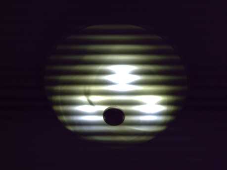
6" mushroom diffuser table lamp with switch
The two LEDs face left
and right, hence the darker band in the middle.
General LED lamp circuit with 2.9 volt LED emitters.
An installed light fixture doesn't need a switch if it's run from a
wall
switch.
I threw the first
'mushroom' lamp together with two emitters and a .27 ohm resistor, and
a power adapter plug at the bottom of the PVC pipe. The only suitable 6
volt, 1 amp power adapter handy was my 'universal' one with settings
from 3V to 12. It turned out that the different settings made for a
great dimmer switch with several brightness levels, each a little
brighter than the last!
It also showed how the power adapter's efficiency drops
when its output rating is neared and exceeded. At the "7.5 volt"
setting, it drew around .03A (just 3 or 4 watts) from the AC line; at
"9 volts", .06A (7 watts); and at "12 volts", .12A (14 watts -
and the adapter gets very hot). At
the same time, the LED current was a little under an amp at "9 volts"
and a little over an amp with the "12 volts" setting - certainly not
double. (I didn't measure at "7.5".) The brightness at only 3-4 watts
(1.5 or 2W per emitter) surprised me. You could easily read sitting by
it, though 7W was better. The "6 volts" and "4.5 volts" settings
dropped the brightness considerably, and the light went out at "3
volts". (In fact, 5.8 volts are needed to overcome the forward drop of
two emitters, so the voltage at "4.5 volts" must have exceeded 5.8 with
the light (bad pun alert!) load. It's common for unregulated adapters
to be considerably
higher than they say with no load.)
Later I added a switch, and a 4700uF, 25V capacitor to
reduce 60 Hz flicker. Still later, I found black ABS floor flanges for
the pipes that make a stable if not decorous base.
'Installed' LED Light Fixtures the Simple Way: a path to the Future!
Then it started to occur to me that all that was needed
for 'semi-permanent' LED mushroom light fixtures on ceiling or wall was
a short length of pipe and the base. The base had screw holes for
mounting. But this idea got even simpler!
Globe light fixtures suddenly started to look ridiculously
easy: a 3" PVC pipe endcap, the globe, and (obviously) the light
circuit parts. Holes could be drilled through the end of the cap to
affix it to the wall or ceiling, one on the side to plug in the power
adapter, optionally one for a switch, and a couple more to let heat
out. And of course three screws 1/4" from the open end to hold the
globe, which would be put on after installation.
There would be no permanent wiring to add. It would hardly
be more work than hanging a picture! To move or remove the fixture,
just take the globe off and unscrew the screws holding the base. The
only mildly objectionable feature (don't look!) would be the external
power adapter
and its wire. Where the adapter could be mounted in an existing light
fixture with the screw-in receptacle, the same switch on the wall can
be used to turn it on and off.
Essentially, it was my kitchen counter light with the base
of the endcap screwed to the ceiling instead of hanging, and the power
adapter plugged in instead of hard wired to the light. On the 17th, I
put one in my
bedroom.

When mounted on the angle of a sloped ceiling, a mushroom diffuser
would look more lop-sided than a globe.

Inside the light. (Yes, you can fit the globe over the fanfold aluminum
heatsink et al.)
With a 1 ohm resistor, the current was 1.1 amps, so the
LEDs (at 2.9 volts each) were using 6.4 watts - and the resistor 1.2
watts. The AC current was around .09 amps, or about 11 watts power in.
This made the brightest light I've had in the bedroom. So the power
adapter (6V, 2.1 amps) was using almost 4 watts. However, this same
adapter uses a watt or two even without a load, so little better
efficiency could be expected from it, except that if its voltage had
been a little lower, I could have used a smaller resistor.
With the 4700uF/25V capacitor I used, no flicker at all
was evident. In fact, this one
light
continues to glow dimly and then ever more dimly for a couple of minutes
after it's shut off. It makes a good night light to see my way into bed
after I turn it off!
Same as the kichen counter,
I ran the wire through a plastic clip that I screwed to the
light fixture so that if an adapter ever comes unplugged, it won't
fall. (in this case onto my bed.)
I mounted the fixture at the next rafter over.
The same idea could be used
with mushroom fixtures. I bought a new 10 foot piece of 3" PVC pipe,
and to my chagrin
it's slightly smaller than the old one, and the mushroom
diffusers don't quite fit in. (maybe if I sand the pipe on the inside?)
I visited a house where LED lightbulbs from Wallmart were
in use in the kitchen. There were four fixtures hanging spread out from
the kitchen ceiling. The light, from many small emitters in each
"bulb", mostly pointed downwards, though they had better spread than my
Canadian Tire one. After you looked towards one, you saw spots in front
of your eyes. I put my two-emitter LED mushroom table lamp on the
counter. The kitchen seemed much brighter with it than without it, in
all
directions, and there was no penalty for looking towards it.
So I'll continue doing it my way with the Cree XM-L-H
(2.9V), the nice '500 lumens' 9V ones with no I.D. (DealExtreme.com SKU
5876)
or similar emitters, frosted diffusers, and a DC adapter.
I'll try the constant current drivers tho - they just might be more
efficient than the power adapters & current setting resistors,
though less convenient since they have to be wired into the 120 VAC.
Dye Sensitized Solar Cells Project
I haven't had time
to return to the DSSC solar cell project to try and make actual,
working solar cells. But I think I should write up my later, though
untested, concepts on the subject - before I
forget them myself. Some of the planned materials and methods are
different from what others have done before, and the ideas are way
ahead of
the actual implementation. I fear these ideas might go to waste without
ever being constructed and tested. Perhaps they might add value to
someone's
future designs even if I never get back to it myself. So the DSSC Solar
Cells project seen mainly in newsletters #28 & 29 is back, if only
as a cross section diagram with
some explanatory notes, in this issue.
The first special newer idea was that the borosilicate
glaze with nanocrystalline titanium oxide would probably be even more
useful as a front cover
glass than in a rear reflector. (The first borosilicate nanoparticles
were made in Sweden in 2008.) Without having attempted to properly test
it, judging by other borosilicate glasses, it should be most
transparent in the visible light spectral area (400-700nm) where the
energy of sunlight is the strongest, and it should block shorter
wavelength UV light, which will prevent deterioration of the internal
components and the dye.

Typical borosilicate glass (lower) has very good transparency where the
sun's energy is strongest,
but is opaque to the damaging far ultra-violet
A second idea is to use
tartrazine (yellow food dye - grocery store) as a dye, probably in
combination with blackberry juice dye, to better absorb the whole
spectrum. (The dye currently
in favour is an uncommon, pricey substance found at scientific
suppliers. If those are the sort of things you try out, they're what
you'll
find... I just bet more common and cheap dyes can be found that work
just as well!)
Then, a related idea
is that the dye(s) can probably be 'set' in the TiO2 to make them
permanent. The chemical to do this would be a thiosulfate. Thiosulfates
are "used to set dyes in textiles". ...Or maybe here in titanium
dioxide.
A third special idea is to use zinc oxide as the
electrolyte instead of iodine and iodide. The zincate ion, so
troublesome for using zinc as a rechargeable battery negatrode, can
transport the electrons back from the rear electrode to the front.

DSSC
1. Nanocrystalline borosilicate cover glass
2. antimony-doped tin oxide - conductive electrode collector
3. dyed sintered nanocrystalline titanium dioxide
4. zinc oxide electrolyte space
5. wire grid electrode collector
6. nanocrystalline borosilicate glass rear reflector
7. titanium oxide glaze
8. porcelain bottom cover
http://www.TurquoiseEnergy.com
Victoria BC