Turquoise
Energy Ltd. News #101
covering June 2016 (posted July 8th 2016)
Victoria BC
by Craig Carmichael
www.TurquoiseEnergy.com
= www.ElectricCaik.com
= www.ElectricHubcap.com
= www.ElectricWeel.com
Month In Brief
(Project Summaries)
- Commercializations? - Variable Torque Converter (PGTC) Transmission -
Taxes - LED Lighting - J1772 adapter - Rocket Stove
In Passing
(Miscellaneous topics, editorial comments & opinionated rants)
- Climate Chaos: Jet streams weaken, cross equator - Mass
Animal Die-Offs - Speculation to Help Fuel High Food Costs - Very Hot
Drinks Linked to Esophageal Cancer - Coffee is good for you - Precious
Metals Price Breakout - Screw for Denmark! - BREXIT - A War Would
Have No Winners - Dimetrodon: Contrary Statements? - Huge Beetle (what
is it?)
- In Depth
Project Reports -
Electric
Transport - Electric Hubcap Motor Systems
* Electric Hubcap motor, Chevy Sprint & Variable Transmission:
- Take-apart of Sprint manual transmission
- Two-Sun Planetary Gear?
- Simplification: differential gear to replace planetary gear
- Slipping gear to link to drive shaft to return previously
wasted energy
- The Sticking Brake: Half the Problem All Along!
* Idea for a New Type of Flat Belt Torque Converter: A "Double Barrel
Torque Converter" (might actually be useful?)
Other "Green"
Electric Equipment Projects (no reports)
Electricity Generation (no reports)
Electricity Storage - Turquoise Battery
Project (NiMn, NiNi, O2-Ni), etc. (no reports)
June in Brief
I seem to have written on many noteworthy topics in In
Passing, mercifully rather briefly on each one. Several of them
seem to form a linked chain of topics.
What project work I did was on the variable torque
converter for the Chevy Sprint. No other projects even made the radar
screen in June owing to busyness with other things including last
year's corporate tax return.
Commercializations
I dream about commercializing some of the
technologies I've been working on for so long now. And I believe it
will happen. The world is now changing rapidly. As good-hearted people
of means realize that new energy technologies just aren't happening the
way they ought to be, some get interested in contributing to the
planet's future themselves. And of course there is very good potential
return on investment to
be made in such fields. And I have made much progress over the years on
various things, and these newsletters may occasionally be read by
people with connections.
Someone has introduced me to an intermediary to another
potential source of green energy funding. Specifically mentioned was
ocean wave power. This seems like a very good,
doable project, starting of course with a pilot project installation -
perhaps somewhere in the west coast wilds where they aren't on the
grid? And successful larger installations could bring in fabulous
ongoing
revenues to the makers and investors... and dare we imagine, lower
power bills for
everyone?
Some of what I've been busy with, contributing to a delay
of this newsletter, is correspondence with those interested in this
project.
Communications have focused on an ocean wave power
project. But
the green energy funders might have a broader view too, and it would
also be nice to discuss the possibility of commercializing the Electric
Hubcap motors, as well as further developing even better motors and
controllers, and the torque converter transmission (which with a
further improvement I now believe will be marvelous). And perhaps
smaller things like the CAT standard 12VDC wiring products, LED space
and grow lighting, and solar connection products.
The nickel-air batteries and perhaps the VHE ray
converter/electric generator will be mentioned as well, but I want to
concentrate at first on the more developed things where investors will
see a clearly definable path from start to finish, to salable products.
Rick Linden's floating river hydro is surely worth a
mention at some point, too. I could see that being scalable from little
auxiliary units carried around for camping on creeks to giant permanent
installations on major rivers for helping to power the grid. This is
especially applicable to BC where there are fast-flowing streams and
rivers everywhere.
But for now, the wave power!
I met with Jay James, the son of someone I know, who
wanted to make a new design in plastic, and wanted to know more about
3D printing, possibly to make a prototype. It was a possibly useful
design, but I didn't think he'd get anywhere marketing it. He mentioned
he lived off the grid with 12 volt power.
I thought of the CAT standard 12 volt wiring system I had
come up with. Seeing how I've done so little with it myself in a couple
of years and since I was potentially frying bigger fish, and seeing he
had experience with 12 V systems, I suggested that if he wanted to try
to commercialize that, to make them, sell them and install them, it
might be a good business proposition for him and I would help out where
I could. I showed him my plugs, sockets and wall plates, and gave him
some samples. I think he was excited by the prospects.
Variable Torque Converter (PGTC)
Transmission in
Chevy Sprint:
- Sticking Brake has been a main source of problems all along!
- New Configuration with Differential Gear & 2 Pulleys will
return slipping belt energy to shaft.
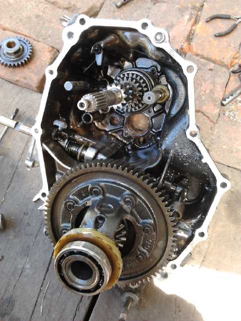
 I managed to
pull all the
gears and things off the transmission shafts of the manual Sprint
transmission without damaging anything
in order to re-configure it into a "double sun planetary gear". I
wasn't sure how it could be done, and on the
9th it occurred to me to see
what others had done along those lines on youtube. I kept
thinking that the 20 ton hydraulic press was the right tool... but I
couldn't see how to fit things into it to press in the right places.
The tiny space between each gear was a big problem for inserting
something solid between them. I finally just put the press on the
biggest
gears and a couple of times pressed several off at once. But it worked,
with 3 to 5 tons of force each time.
I managed to
pull all the
gears and things off the transmission shafts of the manual Sprint
transmission without damaging anything
in order to re-configure it into a "double sun planetary gear". I
wasn't sure how it could be done, and on the
9th it occurred to me to see
what others had done along those lines on youtube. I kept
thinking that the 20 ton hydraulic press was the right tool... but I
couldn't see how to fit things into it to press in the right places.
The tiny space between each gear was a big problem for inserting
something solid between them. I finally just put the press on the
biggest
gears and a couple of times pressed several off at once. But it worked,
with 3 to 5 tons of force each time.
A second reason for disassembling it was that I thought I
might use the whole transfer case and have an oil-lubed system.
But soon I was onto another idea: I had noted long ago
that a differential gear, like a planetary, had three separate
connections. A video reminded me of this idea. If only one wheel of the
car was driven, the heavy
differential gear could be used for the variable torque converter. I
had originally dismissed the idea of driving only one front wheel out
of hand. Upon reconsideration, it seemed like just the right thing to
do. By using the left side as the slipping gear, one could get a
variable rate to the right wheel.
While the wheel was apart, I went to an auto parts store
and I replaced the front left brake cylinder. I knew all along that it
had been sticking, but it didn't seem to be much. However, the
car was so much easier to push I immediately realized that it had been
a
considerable part of my problems all along! It knocked 20 or 30
foot-pounds off the force needed at the wheels to start the car
rolling. Not only would the planetary gear torque converter have worked
better (and I might have even licensed the car and run it on the back
streets), but some of my earlier and more adventurous designs, such as
the magnetic impulse torque converter as well as the centrifugal ones,
might at least have got the car moving.
 Then a superb
refinement occurred to me. The left side
slipping shaft ended up being under the extended motor drive shaft, and
it
turned the same direction. Instead of slipping the pulley to a stop, it
could be slipped to another pulley on the drive shaft. Thus much of the
slipping force would add to the motive force to help bring the wheel up
to non-slip speed rapidly, instead of being wasted. Instead of a rope,
since everything was now rotating, it would be easier to use a flat
belt and an idler pulley to tension it.
Then a superb
refinement occurred to me. The left side
slipping shaft ended up being under the extended motor drive shaft, and
it
turned the same direction. Instead of slipping the pulley to a stop, it
could be slipped to another pulley on the drive shaft. Thus much of the
slipping force would add to the motive force to help bring the wheel up
to non-slip speed rapidly, instead of being wasted. Instead of a rope,
since everything was now rotating, it would be easier to use a flat
belt and an idler pulley to tension it.
It appeared I could use the two flat belt pulleys I had
made on the 3-D printer quite a while back to get a reasonable drive
ratio (albeit the driven wheel would turn the opposite direction from
the motor... so what?), and the same 'poly-V' belt I had been using as
a flat belt.
some of the pieces including a couple of the manual transmission pieces
proved to be just what I needed to attach the pulleys.
This time I would put sides on the pulleys to keep the
slipping belt from coming off one side somewhere. And this time there
was room around them for some fat side pieces. I got some aluminum
scraps the right size at AGO, and large hole drills for the center
holes on the 28th (each one was a different size) and did some work on
the 29th, but mostly I was too busy with other things to work on it.
The aluminum 'idler pulley' (which I had also made) and
its mounting and
connection for the driver to tension it will have to be installed.
Completion and installation of the components, and testing, will be
done in July... I hope.
Tax Return
In off hours now and then since the start of March I had
finally decided - based on looking back through TE News issues - what R
& D projects to report to Canada Revenue for 2015. Then I roughed
out what to say about each one for the SR & ED tax credit program.
Then I sorted out receipts for materials I had purchased for each
project in that year and added them all up. About the middle of the
month, with my accounts getting low and having a lot on credit cards, I
started thinking I had better get serious about it, as my potential SR
& ED tax credit refund will be my main source of income for the
work of
2015 in order that I may continue in the latter part of this year. So
the projects finally were set aside for 10 days to accomplish
this and I finally put the package in the Canada Revenue drop box on
the 24th. It probably would have taken at least a couple of weeks or so
overall - 14 plus days - if I had been able to sit down and do the
whole thing without other diversions. It looks like I'll get about
15000 $ for my efforts of 2015 (not to mention the time spent writing
it up), but of course I spent much of that on materials. Really, the
reverse mortgage on my house has provided most of my working funds in
recent times.
Here are some projects of interest by others.
LED Lighting
Jim Harrington has been pursuing LED lighting and
especially grow lighting with more energy than I've had for it for a
couple of years. Jim's philosophy is to use all the "off the shelf"
parts he can find, use them in innovative ways, and build only what he
has to. (The spring being unusually warm, I got a good garden going
outdoors and am ahving early crops without needing lights. To continue
into fall and winter, however, I'll need to expand my own grow light
selection. I have the components!)
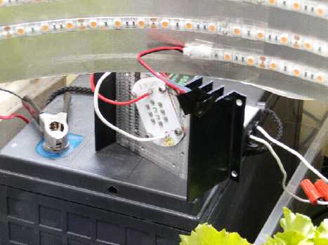
 L: A 30 Watt red-blue plant growth LED emitter,
mounted on a heatsink. This stays pretty cool.
L: A 30 Watt red-blue plant growth LED emitter,
mounted on a heatsink. This stays pretty cool.
A 260 watt solar panel and batteries are used to make 24 volts for
red/blue 'sunlight' indoors,
and to extend the day into the evening.
If used without a diffuser, it should be mounted so one can't look
directly at the emitter.
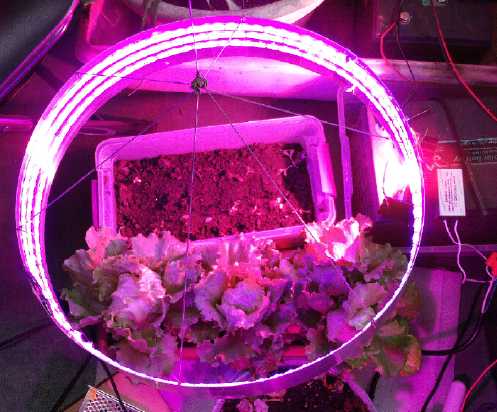
R: Jim's ring light shown previously, growing some small but good
looking heads of lettuce.
 The leaf lettuce has been getting tall and
spindly - a sign it doesn't have enough light.
The leaf lettuce has been getting tall and
spindly - a sign it doesn't have enough light.
A new second ring light (R) has a more powerful LED strip - 30 watts
instead of 10,
for greater light intensity.
Electric Car J1772 Charger Adapter
 Eric Jenkins
has put together an adapter to plug his 1981 Bradley GTX Electric car
into a 'modern' J1772 style car charging port. His charger was already
240 volts, so it just needed the 'dryer' socket, J1772 plug, and
components to tell the charging station the car was plugged in.
Eric Jenkins
has put together an adapter to plug his 1981 Bradley GTX Electric car
into a 'modern' J1772 style car charging port. His charger was already
240 volts, so it just needed the 'dryer' socket, J1772 plug, and
components to tell the charging station the car was plugged in.
He's lucky to be able to plug in there. Plugging into a
regular outlet, one gets hassles. "We don't allow plugging into our
regular outlets!" or "You can't run an extension cord across a
sidewalk." These spurious objections have been at the very same
buildings where thousands of dollars have been spent putting in the
'special' charging stations for vehicles that can use a lot more
electricity to charge for free.
I've been complaining that they put in no neutral pin on
the J1772 charging system, and there's a 'ground fault' detector, so
one can't use the ground as neutral, so the whole thing is useless if
you have 120 volt chargers.
It affects those with handicap scooters, road scooters and
e-bikes, too, who could be using these outdoor-safe charging stations
if they had 120 volts.
Someone has said that the thing to do is to make the
ground connection elsewhere, like with an alligator clip to the metal
on the charging station post itself. Maybe I'll try that sometime.
Thanks J1772 designers for creating a deficient system
that doesn't meet half the real needs out there, and so has needed
upgrading from the moment it was put into service!
Rocket Stove
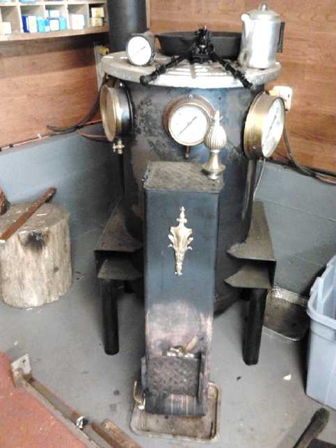 Rick, a
retired plumber I used to work with in the Victoria School District
long ago, has in recent years been creating interesting energy products
such as solar hot water collectors, gassifiers to run cars from
firewood, and a couple of rocket stoves.
Rick, a
retired plumber I used to work with in the Victoria School District
long ago, has in recent years been creating interesting energy products
such as solar hot water collectors, gassifiers to run cars from
firewood, and a couple of rocket stoves.
The rocket stove is interesting in that it burns small
bits of wood very efficiently. The burner is at the front. It is fed
from the top, and burns at the bottom, so if sticks of wood are fed in,
they get shorter and shorter, with the bottoms always falling down to
the fire level.
The flame goes through a pipe into the center of the round
cylinder at the rear. Air is fed in to burn any remaining smoke at the
bottom of the cylinder. (or is it the top?) The warm exhaust air
travels to the chimney around the outside.
By the time it's going out the chimney it's cool and clear
of visible smoke. In operation it has a whooshing sound like a rocket.
The disadvantage compared to a woodstove is that in taking
small loads of fuel, it has to be fed quite frequently. There are
however some interesting designs of larger partly 'earthenware'/pottery
rocket stoves for heating houses on the web and on youtube. The clay
holds the heat for hours.
In Passing
(Miscellaneous topics, editorial comments & opinionated rants)
Climate Chaos: Jet streams weaken, cross equator
Earth's stratospheric jetstreams normally run East to West
in four bands of high speed winds: The northern and southern
tropical-temperate and temperate-arctic jetstreams. These normally
separate
the tropical, temperate and arctic climates. Climatologist Paul
Beckwith
[you tube channel] at the University of Ottawa's Laboratory for
Paleoclimatology has done a great video lecture showing how the
jetstreams have become weak and chaotic, leading to severe arctic
warming, cooling and even glaciers in areas in temperate latitudes
(which is probably why some people think there's global cooling rather
than warming), and a decrease in
seasonal temperature variations. They have never become chaotic like
this or crossed the equator before since weather
records have been kept, except in the last couple of years. He says we
may even have a "blue water
event" (meaning little or no sea ice, I presume) in the arctic ocean by
August this year. (The real-time maps of winds at various altitudes can
be found at a website called earth.nullschool.net
for those interested.)
He describes many strange and record setting weather
phenomena. He ends with some important conclusions: "There are very
strange things happening on planet Earth. I can't stress how important
this is to the climate system. You can look at my other youtube videos
to help understand this better. We need to declare a climate change
emergency. We're going to have massive hits to the food supply. We're
going to have massive geopolitical unrest."
Beckwith doesn't mention causes of the problem in this
video. The
obvious main cause is the somehow invisible elephant in the room, the
USAF's nearly worldwide, highly energetic 'geoengineering' program:
the spraying of chemicals like coal ash high in the sky from jets, and
blowing away the ionosphere with mobile HAARP machines mounted on
ships, trains or wherever.
Globally, old records for heat, drought,
and flooding are being broken almost daily. And the sprayed chemical
'fertilizers' cause huge
algal blooms. As the algae dies, its decay leaves oxygen depleted
water. In Florida this week an algal bloom so bad it's "like guacamole"
has prompted declaration of a state of emergency. (It's bound to lead
to some marine mass die-offs.)
Unfortunately, looking at one of his other videos, it
seems Beckwith sees aerosol spraying as part of a solution, not the
problem. Reduced sunlight penetration however is countered and more by
the insulating effect the particles seem to have on the atmosphere,
reducing cooling off at night. Perhaps they reflect infra-red heat back
to the ground just as well as they reflect sunlight. And he ignores too
the many deleterious side effects: droughts, flooding, ocean
acidification, algal blooms and die-offs. It looks like the people
deciding to do these things have little real idea of the effects of
what they're doing, just academic theories, and see these disasters as
reasons to redouble their efforts, not as results of their programs.
But why have the problems so rapidly become so much worse, exactly
since they started them?
The one and only real and effective solution is obvious:
to stop polluting the air by switching from burning fossil fuels to
electric transportation and other equipment. Along with electric cars,
if we electrify and modernize the railroads it would eliminate most of
the air traffic, especially for freight. Electric CNC farming machines
would eliminate most of the petroleum use on farms. Once the fossil
fuel burning is greatly reduced, everything then will solve itself.
Anything else is essentially a distraction, not a solution.
Seeing the effects on the jetstreams, and the arctic
meltings and methane releases, I can't imagine weather patterns
returning to normal in anything less than a decade once all the problem
activities (meaning at this point the geoengineering much more than
fossil fuel use) are stopped. Possibly it will take much longer - even
centuries.
 My amateur rendition of a panorama of
chemtrails over Victoria BC, July 2nd 2016,
My amateur rendition of a panorama of
chemtrails over Victoria BC, July 2nd 2016,
whipped up by gusty winds into artistic brushstroke
shapes ... somewhat reminiscent
of the odd, broken patterns of the jetstreams around the world map.
Some hours
earlier these formations had been more a pattern of straight lines,
with a giant "X"
right over the town.
Mass Animal Die-Offs
Perhaps you've seen a mass die-off or two of sea life
in the news. It's horrifying to think of the bulk of a whole population
of starfish, sea lions or marine birds being wiped out of the ocean in
one fell swoop. But even this gives little hint of the scale of what's
happening. Whatever anyone thinks about a site called
"end-times-prophecy.org", I got a link to their page about mass fish
and animal die-offs. It staggers the imagination! There are more mass
die-offs happening around the globe than there are days, and many days
have 2 or 3 mass
dieoff stories - there were even a couple of 5 story
days. The list for 2016 alone goes on and on. Each one has a link back
to an original news article from a reputable source. http://www.end-times-prophecy.org/animal-deaths-birds-fish-end-times.html
One starts to get a disquieting picture of life, especially marine and
aquatic life but not limited to that, dying off at a furious
pace all over the planet.
While some of the mass deaths have specific known
causes, I have no doubt that the bulk of the carnage is directly or
indirectly attributable to the various effects of 'geoengineering'.
Speculation to Help Fuel High Food Costs
"Trade Genius" Bob Kudla on Next News Network, said that
speculators are latching onto what is turning into a bad crop year
because of various climate anomalies in widespread areas including
China,
Europe and the USA. They are buying up futures contracts on crops so
that if there are scarcities, they will have control of the remaining
stocks. This by itself (even where there's enough to go around) will
drive prices even higher over the coming fall and winter as they hope
to take big profits from their speculations - at the expense of the
eating public. One more reason to stock up some keepable foods! And
probably one more reason we need to change some of the ways the world
does business!
Precious Metals Price Breakout
Many analysts have been saying over and over for several
years that as things get worse, having real
property - things of value like precious metals in your own hands -
will be
almost the only way to preserve your wealth through the chaotic period
they see coming.
People seem to be catching on, and the precious metals are now rapidly
climbing in price. Silver went up by over a dollar on Canada day
(Friday July 1st) alone, from about 18.60 to 19.75 $US. (It was about
14 $US at the start of the year, and it's well over 20 as of Sunday
night.) There may be 'pull-backs', or they
may just keep climbing. But in the coming months, or year, or maybe
two or even three, they and all commodities will reach prices that will
make us all
gape in awe, as that vast pool of paper money printed in the last
decade and more all
chases desperately after the same quantity of real goods, causing
hyperinflation and finally complete loss of trust in and the value of
fiat currency. Venezuela is a great example of what happens.
Very Hot Drinks Linked to Esophageal Cancer - Coffee is good for you
WHO's (World Health Org.) IARC branch (Int. Assoc. for
Research of Cancer) has linked very hot drinks, drunk at over
65-70°c, with cancer, in particular esophageal cancer. The trouble
is as you'd suspect: the hot liquid burns the lining of the throat,
causing damage over and over as the drinker makes a habit of it. Hah! I
always thought that, surely, scalding hot drinks couldn't be good for
you!
In the same RT.com article, IARC looked at over 1000
studies that all show coffee has no apparent link to any cancer.
(Unless of course it's too hot, I presume.) In fact moderate coffee
drinking reduces incidence of death from diabetes, heart diseases and
neurological diseases. No mention of whether that was with or without
cream and or sugar. Or whether it was Arabica or Robustica coffee (Low
or High caffeine coffee subspecies). Perhaps it makes no difference?
Screw for Denmark!
Birth rates in the developed world, which mostly means
where white people live, have been below replacement values for decades
now. But in some parts of the "undeveloped" world, birth rates are
still very
high. Now a national government has pointed out the obvious: that if
white people don't start having more kids, they will have to let in the
hordes of surplus people from places where they have foolishly,
thoughtlessly, ignorantly or otherwise failed to control their
population growth. White people will soon be in the minority even in
North America and Europe where they have been the bulk of the populace.
In the USA as of last year, white babies became a minority. Will this
trend increase until there are no more white people? What will happen
to advancing culture? While
the white races need perhaps more than most to curtail reproduction of
their defective, degenerate and antisocial stocks, I can't see the
submergence of their - our - genetic and creative potentials as being a
good
thing.
The Danish government has started the "Screw for Denmark!"
advertising campaign pointing out that Denmark as a people and culture
will vanish unless they start having enough children to keep schools
open and to support the present population when they are elderly. "Take
a vacation. Go to Paris. Go to the beach. Have a good time. Relax. Have
some good sex." And the campaign, not a year old, in combination with
local campaigns, is having its effect: the birth rate has gone up.
Denmark's schools are to stay open.
'Screw for Denmark' sex campaigns
produce baby boom in months ...
https://www.rt.com/news/345499-denmark-baby-boom-sex/
A racy ad campaign, started only nine months ago, has
really hit the spot for Denmark's campaign for more baby-making. The
country now ...
A Danish TV ad for the campaign ends in English with "Do It for
Denmark!"
I will also remark along these lines, that as I saw the
reduced birthrates
here in the 1990s and closings of a few schools here and there, and a
reduction in immigration from other parts of Canada, I was relieved. I
expected life would get easier, without the unrelenting pressure from
more and more people competing for the land and resources, without the
need for never-ending urban expansion. It seemed our problems could be
solved. Homelessness would end. Traffic would stop getting heavier and
heavier. Competition would decrease and co-operation and leisure time
would increase, and the three core values of social sustainability
could take root: an improving quality of life, equality, and
opportunities for fulfilling, growing living for all. Could it be that
some sort of Utopian living standard for all was within sight?
Instead our governments, Canada and BC, simply started
letting in more and
more immigrants from ever more overpopulated lands, and life has kept
getting
harder and harder for everyone. This is partly the fault of the western
unsustainable debt-based financial system, which relies on an
ever-expanding economy borrowing ever-expanding debt to avoid
deflationary debt collapse. It can't
permit a stable population and economy! Chaotic as its fall will be, no
one will miss it after it's gone.
BREXIT
A European Union is a fabulous idea - even an
inevitability - but the structure of the
present organization was very badly thought out. There's no one in
overall charge, and an expanding, corrupt and overpaid autocratic
bureaucracy has grown up from which there is no democratic appeal. The
European central bank and European Commission (not to mention the IMF),
out of harmony with real needs and again with no appeal process,
dictate to nations what they shall do. We see the disasters they've
made of Cypress and Greece, apparently with more countries to follow
those into the abyss.
Near the end of June, the people of Britain voted to
disassociate their land from this costly, corrupt autocracy. I looked
on Google Earth,
and there is already to be seen a wide channel of water between Britain
and the rest of Europe. By autumn, barring a second and contrary vote,
they should
be well out into the mid Atlantic.
Having retained their British Pound currency, they are in
a much better position to leave than most European nations. (I still
remember then prime minister John Major keeping them out, saying the
Euro currency was "deeply flawed" in concept. Apparently he was right.)
A War Would Have No Winners
In the past, various nations, or more usually their
leaders, have agitated for and started
wars. In prehistoric times, genetically unprogressing, unfit or
degenerate groups, sometimes hardly more than animals (which we did
evolve from, after all), could perhaps be
annihilated by savage war, genetically improving the overall human
population. In ancient times, city states, and then empires could be
built by
military expansion - but by then usually to the detriment of the
general civil
population
of the empire, conquerors as well as the vanquished. In the 19th and 20
centuries, wars became more and more devastating, each one costing
millions, then tens of millions, of lives. Even in the limited Middle
East wars millions have died and tens of millions have been displaced,
becoming refugees from bombed ruins that used to be cities, now with
nowhere to go.
Wars escalate. If there was ever another major war,
casualties might be
numbered in the billions, and might even include everyone. If not,
there
would still be devastation everywhere with major portions of the globe
rendered uninhabitable long into the uncharted future. Some in the
ruling circles in the USA think they can "win" against Russia with a
sudden nuclear strike. Even if they got exactly their way, and the
largest country in the world was wiped off the map without firing a
successful
shot in reply (more than unlikely), execution of this plan would still
probably doom us all
to a painful, lingering death by gradual but unrelenting radiation
poisoning.
And if by some miracle the rest of the world could somehow
carry on? What, exactly, would have been won by utterly destroying the
object of the attack? Booty? Poisoned Lebensraum for an overpopulated
America? How absurd! The nations need each other for many reasons. The
planet is too small to toss them away and make it smaller.
Yet the madmen in charge especially in the USA's
"military-financial complex" continually agitate and provoke for war
and turmoil, and to forcefully quell antagonism toward such programs at
home by lies and repression. Journalist Pepe Escobar calls the USA "The
Empire of Chaos" since that is about all they have been leaving in
the wake of their aggressions for quite some time now. Now warships are
sent into the Black
Sea and huge wargames are held in eastern Europe within sight of
Russia's borders "to
promote peace". Warships are sent into the South China Sea to
"assert freedom of the sea lanes" (or however exactly it was phrased).
Such
doublespeak now being heard heard again and again sounds just like Nazi
propaganda from shortly before World War II, or from George Orwell's
book 1984. Predictably Russia and
China have reacted by building and strengthening their defenses. Russia
has created some fearsome new and advanced weapon systems. Would China
be building islands and turning them into military bases if it didn't
feel threatened?
The USA 15 years ago didn't have an enemy in the world.
The "military-financial complex" was threatened by irrelevance. Enemies
had to be created out of thin air to justify it greedily gobbling up
over one
half of the entire US budget! And despite the vast expenditures, the US
is now being outclassed in weapons systems.
Devious intrigues and war are no longer realistic options
for solving anything, if they ever were. Let us pray. Surely the
disastrous
plans of these evildoers will never be played out!
NO
MORE
WARS!
NO MORE WARS!
NO MORE WARS!
But words are only the start. People must regain control over our
societies, not hand power over to elected officials who aren't working
in our interests, or who at least have many conflicting interests
besides ours to contend with. HandsOnDemocracy.org
again has concepts for doing that.
Dimetrodon: Contrary Statements?
In looking up something not closely related in Wikipedia I
ended up
at Dimetrodon and found a statement diametrically opposed to
the one I read earlier on another web site (which one, unfortunately I
didn't note),
which said that bone microanatomy indicated a low metabolic rate in
dimetrodon and edaphosaurus, which would be consistent with their being
aquatic or
amphibious. [all quotes below are from Wikipedia]
"The
exact lifestyle of Dimetrodon (amphibious to terrestrial) has long been
controversial, but bone microanatomy supports a terrestrial
lifestyle,[50] which implies that it would have fed mostly on land, on
the banks, or in very shallow water."
Of course, that still doesn't preclude them being
amphibious, and the author admits it's controversial, but it seems like
the opposite conclusion to what I read on
the other
website. It's also still true that there weren't any seed plants yet,
so there probably were mostly only sparse bugs and fern leaves to eat
except in and around the water. (Not that there weren't some very
large bugs!)
There was also a statement that I had been unable to find
about the young, a mild contradiction to what I had been led to infer
before that they may perhaps not have been found: "Although some
Dimetrodon species could grow very large, many juvenile specimens are
known." But might the eggs still be laid in the water?
Now that I think about it, there's one thing I hadn't
considered, and that's live birth. Even some fish give live birth, so
it doesn't seem impossible some amphibians might have it or once had it.
Hadn't I read the Wikipedia article on Dimetrodon? That
seems amazing
considering how many things I looked up on the subject. Might those
parts even
have been added since I wrote my piece last month, perhaps as a
refutation of it? Most likely I somehow missed it. But other
topics and species the search led me to still seemed to me to validate
my original conclusion, that
all the Permian inhabitants were amphibians until near the end of the
period. Also that there
seemed to be stronger agreement - or at least more and more evidence -
for this than I had realized. For Dimetrodon and Edaphosaurus to have
been reptiles in that early time seems more and more out of place.
In other articles I found that "Reptiliomorpha" happened
to potentially include amphibians from the Carboniferous and Permian,
not just reptiles.
"The name Reptiliomorpha was coined by Professor Gunnar
Säve-Söderbergh in 1934 to designate amniotes and
various
types of late Paleozoic tetrapods that were more closely related to
amniotes than to living amphibians. In his view, the amphibians had
evolved from fish twice, with one group composed of the ancestors of
modern salamanders and the other, which Säve-Söderbergh
referred to as Eutetrapoda, consisting of anurans (frogs), amniotes and
their ancestors, with the origin of caecilians [modern limbless
amphibians living akin to worms or snakes] being uncertain.
Säve-Söderbergh's Eutetrapoda
consisted of two sister-groups: Batrachomorpha, containing anurans and
their ancestors, and Reptiliomorpha, containing anthracosaurs and
amniotes.[5] Säve-Söderbergh subsequently added
Seymouriamorpha to his Reptiliomorpha as well."
Others disagreed with this theory. In one definition,
"Reptiliomorpha" includes only early amphibians - those
presumed to be the ancestors of the reptiles.
"Michael Benton (2000, 2004) made it the sister-clade to Lepospondyli,
containing "anthracosaurs" (in the strict sense, i.e. Embolomeri),
seymouriamorphs, diadectomorphs and amniotes.[4] However, when
considered in a Linnean framework, Reptiliomorpha is given the rank of
superorder and includes only reptile-like amphibians, not their amniote
descendants."
and
"The informal variant of the name, "reptiliomorphs", is also
occasionally used to refer to stem-amniotes, i.e. a grade of
reptile-like labyrinthodont tetrapods [amphibians or pre-reptiles]
that are more closely related to amniotes [reptiles, birds,
mammals] than they are to lissamphibians [modern amphibians],
but
are
not
amniotes
themselves; the name is used in this meaning
e.g. by Ruta, Coates and Quicke (2003)."
[My italics]
Like I said, by getting into the whole subject, one is
entering a labyrinth.
Huge Beetle
 One day in a
parking lot I found this huge beetle, about 2" long, with huge
'antlers'. It didn't like water. I'm guessing it's some kind of forest
beetle, at home under the bark in
rotten douglas fir logs. Full marks if anybody knows what it is.
One day in a
parking lot I found this huge beetle, about 2" long, with huge
'antlers'. It didn't like water. I'm guessing it's some kind of forest
beetle, at home under the bark in
rotten douglas fir logs. Full marks if anybody knows what it is.
Newsletters Index/Highlights: http://www.TurquoiseEnergy.com/news/index.html
Construction Manuals and information:
- Electric Hubcap Family Motors - Turquoise Motor Controllers
- Preliminary Ni-Mn, Ni-Ni Battery Making book
Products Catalog
(Will accept BITCOIN digital currency)
...all at: http://www.TurquoiseEnergy.com/
(orders: e-mail craig@saers.com)
Electric
Hubcap
Motor
Systems
-
Electric
Transport
Electric
Hubcap motor, Chevy Sprint & Variable Transmission
Changing to a Sprint Gearbox - Just
the box?
Instead of trying to find parts that didn't need
lubrication, it seemed to me for a while it might be better to enclose
everything
in a box with gear oil. The best box, if I could use it, would be one
made for the car.
I had bought a Sprint/Metro manual transmission at an auto
wrecker some time ago. I had been unable to disassemble it, but I
thought I would try again. Perhaps if I removed all the convoluted
clutter of gears, shafts and levers, there would be room for one
planetary gear on one shaft, with the slipping mechanism sticking out
one end and the motor on the other, and a chain to the enclosed
differential.
On the 4th I borrowed a large gear puller
from AGO and put it on the gear that wouldn't budge. That and a propane
torch heating it until the bearing balls were glowing finally got it
loose. In the convoluted mechanism were a number of split pins and
things that had to be punched out. I finally realized that the gears
weren't coming out until each piece of the maze of shifter parts that
connected to the gearshift lever was removed first.
I got most of the rest disassembled (besides what I'd done
long
ago) in about an hour and a half. Then I got to the rod that connected
to the shift lever. In a deep recess was a bolt holding a piece on the
end of the shaft that kept the whole rod from sliding out. I loosened
the bolt, but there just wasn't quite enough room to pull it out, and
its end still stuck in a bit and kept the rod from coming out. How had
they done that? I finally had to give up. My mind had a picture of the
recess as being a bump in the casting on the outside. The next day I
finally decided I would drill a hole to pull the bolt out through. But
when I looked on the outside, there was a sheet metal plate cover over
the inside recess, held by 3 bolts. Duh! The bump in the casting I was
thinking of was elsewhere. So having wasted an hour, I removed the
plate, the offending bolt, and the lever on the shifter shaft, and got
the shaft out. Total time now was doubled to 3 hours, over one simple
little thing. Such is mechanics!
 There was over
5" of length available. If I put a
planetary gear on either of the original shaft positions, it could only
be 4" in diameter. If I made a new hole at the center of the space, it
could be 5" diameter. The biggest chain sprocket I could put on the
differential was just 6" instead of 8". That would mean a pretty small
sprocket. It would have to fit beside the ring gear rather than over
it, adding an inch to the length. So the planetary could then be only
4" long instead of 5". Unless I punched out the whole end of the
transmission. Well, that could be done!
There was over
5" of length available. If I put a
planetary gear on either of the original shaft positions, it could only
be 4" in diameter. If I made a new hole at the center of the space, it
could be 5" diameter. The biggest chain sprocket I could put on the
differential was just 6" instead of 8". That would mean a pretty small
sprocket. It would have to fit beside the ring gear rather than over
it, adding an inch to the length. So the planetary could then be only
4" long instead of 5". Unless I punched out the whole end of the
transmission. Well, that could be done!
A New Solar System: The Two-Sun
Planetary Gear?
I looked at all those gears on two shafts, some of them
spinning freely and others fixed to the shafts, and wondered if there
might be some way some of them could be turned into a planetary gear,
but it didn't look possible. There may be some way, but it really needs
a ring gear with the teeth on the inside, and a ring of mobile planet
gears with their shafts circulating freely, meshing between the other
two.
Or was there some other way? Let's see... If a shaft had
one
fixed gear and one floating gear to replace the sun and ring gear, one
might contrive to put on two concentric "washers" on bearings, that
could circulate around the main shaft. Between the two washers there
would be short shafts with double gears affixed to them. One gear of
these
pairs would mesh with the fixed gear and the other with the floating
gear.
This would constitute a planetary gear. And all the gears would have
outer teeth, no inside ring. The two gears must be different diameters
to match the different main gears, and the ratio is any desired ratio
except one-to-one, but preferably substantially different. Whatever the
ratio, the freely rotating "planet pairs" assembly will need axial
stiffness
beyond that needed for the regular type.
Then, let's see... one end could be driven by the motor.
That could be considered either the "ring gear", if it was the larger
one, or the "sun gear", if it was the smaller one. But we want the
slipping mechanism to be on the smaller "sun" gear. Or on the "planet'.
Now... how do we get the gear elements connected to where they need to
connect? Concentric shafts? Slipping pulley inside the housing? If two
connections were internal, it *could* be all mounted on one solid shaft
with a bearing at each end. The possibilities, the possibilities!
Wow, I just might save that couple of thousand dollars
that I was about to spend on a planetary gear after all! Time to give
the whole thing a lot of thought! And see which gears can mate with
which in there. There were in fact 5 pairs of gears which mated on the
two shafts, one fixed and one floating on each pair, all of them always
turning on both shafts, while only one pair is engaged for any of the 5
speeds. (No wonder transmissions gobble up 30% of the power put into
them!) Reverse has a slightly different arrangement with a third gear
connecting across the two shafts and changing the direction from the
others. It's also straight ("spur") gears instead of helical, giving
that typical "backing up" sound when in use.
Of course, there could only be one "planet" instead of
several,
made from one pair of gears. Well, they're the same gears that were
singly driving the car before. But there wasn't room for them inside
the case if the planet had to circulate around the main shaft. The
diameter became 6" or more. I'd have to hack up the case. Well, sobeit.
I occurs to me that surely people must have thought of
this arrangement before, probably many times. There are lots of people
with far more devious mechanical minds than mine! They should be easier
to make - why have we never seen such gears? On the other hand, there
was that guy that said he worked at GM's main plant in the 1960s-70s,
who said the engineers there would cry over all the patents for
improved things that GM had bought up and stuffed into the drawers,
which they weren't allowed to use in designing new vehicles. They might
have even had the variable PGTC before. So much priceless technology
has been held back from us! Well, the internet is putting an end to
that.
(Are those "planetary" gear names still appropriate? Well,
"ring gear" never did fit with "sun and planets". Maybe it should have
been called the "Kuiper belt gear" or the "Oort Cloud"? We could
perhaps call this the "double star" planetary gear?)
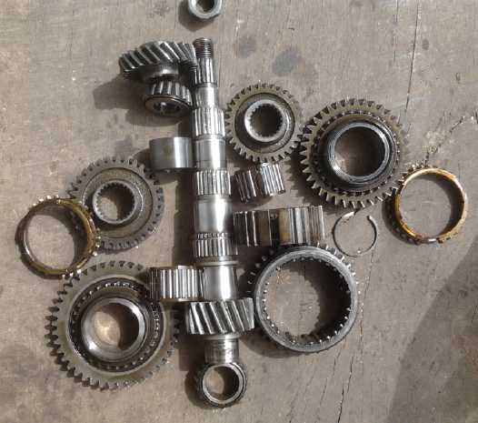
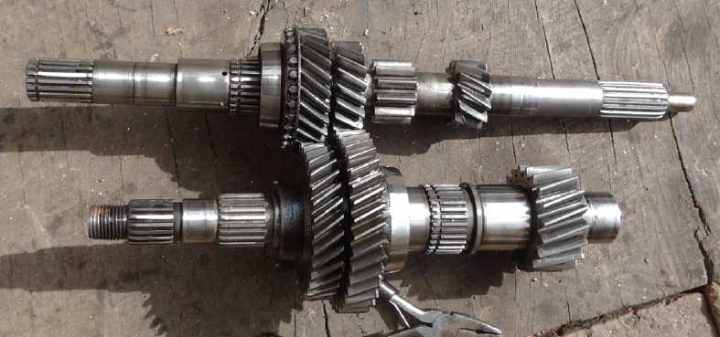
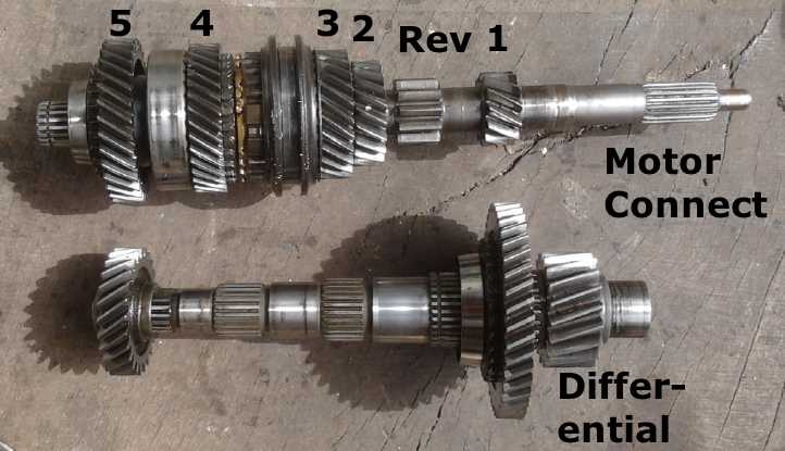 The two shafts from inside the transmission.
Most of the gears have been removed from the output shaft,
The two shafts from inside the transmission.
Most of the gears have been removed from the output shaft,
leaving just first and fifth. For all 5 forward gears, the gears always
rotate against each other, but only
one gear selection at a time has both gears locked onto both shafts.
Helical gears have higher losses than
straight 'spur' gears such as the reverse gears, but run quieter. All
these ever-churning gears doubtless explains
much of the 30% losses of a typical manual transmission. A large
straight gear of the lower shaft for reverse
(not shown) doesn't quite touch the small one shown. A gear connecting
between them is moved into position
for reverse, causing the output shaft to rotate the opposite direction.
Between 3rd and 4th on the input shaft a sliding engager can be seen.
In its current position pushed to the right,
it connects the brownish fixed ring to the third gear. Slid to far
left, it would lock 4th to the shaft instead.
In the center both 3rd and 4th spin freely allowing some other gear
selection. There is a similar engager
between first and second on the output shaft, and one just for 5th at
the left end.
As a side note, I've been told now and then that "fourth
gear goes straight through from the motor to the drive shaft, so it
gives better fuel economy", and that fifth gear is an "overdrive". That
has always puzzled me. Certainly in
the Sprint manual transmission 4th and 5th were just two of five pairs
of gears
continually churning against each other. But then I saw a Youtube video
about transmissions, some sort of training film from the 1950s, and
they actually did make them like that back then. There was a third
shaft, and in fourth, it was disengaged and the engine was indeed
coupled straight through to the drive shaft with all the gears
disengaged. There usually was no fifth gear. Either the newer way is
simpler, smoother or easier to make
or to shift, or it has been made the way it is now deliberately to
prevent
drivers from getting better fuel economy, since it all has been
controlled until very recently by "big oil". (Ever notice that vehicles
never more than just meet government mandated fuel
efficiency standards? They have until recently been worse than in the
1970s.) The way they were once made has become an urban
legend that has had no substance since probably the 1950s or early
1960s. But I
digress.
Gear Shafts Disassembly
I wasn't sure how on Earth I was going to get all those
gears and things off the transmission shafts without damaging anything
in order to re-configure it into a "double sun planetary gear". On the
6th it occurred to me to see what others have been doing along those
lines on youtube. First there was a "Snap-On" gear puller that looked
better than anything I'd seen before. But I wasn't confident it would
do the job. I kept thinking that the 20 ton hydraulic press was the
right tool... but I couldn't see how to fit things into it to press in
the right places. The tiny space between each gear was a big problem
for inserting anything solid between them.
And I noticed that some of the fixed gears weren't pressed
onto the shaft, but appeared to actually be part of the same piece of
metal. That would make it even more tricky! No way to take those off at
all. But that could be accommodated since the mating 'freespinning'
gear for each could be removed.
I started thinking of a large tube that would hold the
whole shaft complete with gears, then a couple of pieces of metal
across the top to hook under the end bearing and first gear to be
removed. (They were too close together to do separately.) Finally I
took the shaft up to the press. Hmm, the fattest gear did after
all fit inside the bottom rest. Okay, forget the tube! And the blocks
that came with the press had triangles cut into the centers as if just
for this sort of thing. Okay, we had the pieces! I put it all in, and a
cardboard box 'cushion' under in case the whole shaft fell down, and
started pressing. When it hit about 5 tons there was a sudden bang. The
gear and end bearing had come loose! Perhaps I could do the next two
gears at once, too, since it would be really hard to get between them.
I found some thinner (3/8") slabs that would fit and pressed again.
Again it banged loose suddenly, at 4 or 5 tons. The two fixed gears I'd
now pressed off weren't just a press fit. They fit on the shaft via
splines. I got the large end of the other shaft apart easily enough,
but I couldn't budge the small end. It seemed they just had to
be a press fit, or else how had they been fitted? In the press I
cracked the first gear teeth. Okay, that was far enough on that! They
could stay on, and I certainly wasn't going to use first gear.
Death and Reconfiguration... then Simplification
 In order to turn these into a "double sun
planetary gear", one whole shaft would have to be able to revolve
around the other.
In order to turn these into a "double sun
planetary gear", one whole shaft would have to be able to revolve
around the other.
This certainly wouldn't make for a smaller gear package than the
regular planetary gear formation.
Once they were apart I
started thinking of how best this
"double sun" planetary gear might be fit together. It looked like I
could use 3rd and 4th gears. Both shafts had one fixed gear and one
floating. Per the plan, the gears on one of the shafts had to be locked
together. Easily done by putting on its gear shifting parts. Then, the
planets shaft had to poke out one end to attach the motor to. (Or the
larger sun gear end, depending on configuration.) That was easier said
than done. But what if I used 5th gear, which was mounted beyond the
bearings, outside the main case, with 3rd or 4th? There was access!
Oops, that was the one gear the rotating "planets" shaft couldn't use,
for that very reason.
But was there some way to do it without one shaft having
to revolve around the other like a planet?
On the 8th I spent the evening watching videos about
variable torque converters on Youtube. They weren't looking very
promising.
Finally one at midnight jogged my memory, that long ago I
had noted that a differential gear had 3 elements and was in
that sense similar
to a planetary gear. It was even a 1 to 1 planetary gear, or 2 to 1
from the drive if one 'wheel' was stopped. How badly did a "pavement
only" electric car need both front wheels driven? I rejected the idea
out of
hand when I originally thought of it, but what if one drive axle was
cut off to a stub and a slipping pulley mounted on it? The differential
would become the variable torque converter. One could contrive to put
in a 3 to 1 reduction chain drive with a 36 tooth (6", using #50 chain)
sprocket on the differential and a 12 tooth one right on the motor - or
on the top shaft of the transmission housing. That way one would have
the original housing containing only the top shaft and differential
with a chain, and the torque conversion slipping pulley on the outside
at the bottom. With no slip the motor would do 3000 RPM for... wait!
with one shaft stopped, the wheel side would go twice as fast, halving
the reduction ratio. So it should be 6 to 1 to give 3000 RPM on the
motor for 1000 RPM on the wheel. That
would then be a 6 tooth, 1" sprocket on the top. That would be a pretty
tiny sprocket! Or it might have to
be 5 or 7 teeth, because there'll be no way to adjust the chain
length to eliminate slack except by changing the sprocket sizes. But
really the smallest sprocket might be about 12 teeth. It would need a
20mm
weld-on center core.
It occured to me that I do have two differentials since I
bought the manual transmission, but I didn't see an easy way to employ
the second one so both wheels could be driven. So I decided to try the
single wheel idea. Also, I note that some original manufacturers' car
transmissions do in fact employ a chain drive to the differential
instead of gears, and it's supposed to be better. You just don't know
it's there because it's inside the transmission housing. I do have
concerns:
1. The whole differential spins, and takes the full force of the drive,
but usually the four bevel gears
inside it only turn slowly, when turning left or right or if one tire
is
a bit smaller than the other (eg, different tire or underinflated).
With this system, they will be constantly spinning except when the
wheel and slip pulling are both turning the same speed. They just might
wear out rather quickly. I'll take that chance.
2. With just 2 to 1 speed increase, will it have enough torque? It
probably will - the original setup had about 3 to 1 slowdown, so that's
6 times faster and so will probably be more like 120 foot-pounds
instead of 20. If the motor speed is here reduced by 6 to 1
(increasing its torque 6 times) hopefully it'll be far more than
adequate. (Given a constant motor speed and
torque, the pulley will slow down as the wheel/car speeds up.)
3. Driving the car with just one front wheel. One rear wheel seems
"more okay" somehow. I know I didn't much like it when one rear brake
wasn't working in the Mazda, but I still drove it that way for a couple
of years until I found that was why it was pulling sideways a bit. But
acceleration is more gradual than braking sometimes is, and the other 3
wheels won't tend to skid even if the driven one does, hence it's much
less critical.
4. If the feel of the car is acceptable driving just one front wheel,
some inspector might regardless say it can't be driven on the street.
That would be really distressing!
But the whole system is so fantastically simple compared
to anything else, with so few parts to buy, I just have to try it.
It'll be a whole big
transmission case with almost nothing in it! If it doesn't have the
torque I'll find out soon enough. I think it will. I'll soon know how
one front wheel drive works out. Assuming that's okay I'll license it
and find out if the differential busts after 500 miles and I have
to have the car towed home, or if it'll still be working just fine 5000
miles later and beyond. I suspect everything will be fine.
The next morning (9th) I went out and looked at the car.
If I jammed up the upper planetary gear or put on a shaft coupling, the
motor would drive the chain to the differential directly with the
present housing and not much change. If I then removed the drive shaft
to the right wheel, I could put on a short stub (spare CV drive shaft
end) to attach the slipping pulley to. Simple! It wouldn't solve the
lubrication problems, but it would be the fast way to get the car going.
Then came the nitty-gritty of the slipping pulley. In
looking at it, the shaft would have to be 6" long for the pulley to
clear the mountings, and then I suddenly realized it would have to be
about 10" or more long to get it past the motor and the flywheel, or
they'd hit. And that would be with any of the available housings,
unless they were arranged to have a considerable space between the
motor and the transmission to accommodate the pulley. If I used the
left wheel instead, there was lots of room right by the housing, even
for a 12" pulley, so that was the choice. The whole tensioning rope and
cable arrangement would of course have to be remounted however I did
it. That arrangement only applied to my housing. The original one stuck
out 6" past the differential on that side, so using mine was again the
choice for a prototype.
As a side note, the first 12" pulley I'd bought for a
flywheel was about 9 pounds. The second one, the double pulley, was
only 11
pounds. I had thought it would be heavier.
Sticking Brake: Half the Problem All Along!
Well, enough writing; the course was clear... Off with the
left wheel! [4 hours later:] While I had it apart, I knew the left
front brake was sticking a bit, so I bought new a caliper and replaced
it. (The pads were like new.) I hadn't thought it would make much
difference, but Holy Hannah! the car was easier to push! It
easily knocked 20 or 30 foot-pounds off the force required to turn the
wheels from any position. The sticky brake had been far more of a
problem than I had realized. Here I had been blaming what I sort of
recognized as extra force all along on "spongy, rough lawn" - and still
not recognizing how much extra force it really was. It also doubtless
contributed to my erroneous conclusion in 2012 that the torque
conversion didn't seem to work until the vehicle was moving.
I can only think that everything I had been trying in the
last couple of months including starting on up-slopes would have worked
- if only barely. I just might have dared to insure it and venture out
onto the back streets for more testing. (If only there weren't so many
steep hills right around here!)
In fact, some of the various more adventurous torque
converter designs like the magnetic impulse one as well as the
centrifugal clutch one might have at least moved moved the car!
(I replaced the right from brake caliper when I bought the
car. It was much worse than the left one.)
What Next?
I had the thought that I could put the drive shaft
back on, put everything back the way it was, and try it out again. It
would be bound to have better results than before. It would probably do
shallower hills okay. Steep ones would probably still be 'out'.
Onward and upward!, I decided. The left CV drive shaft was
now out, and ready to be replaced with a 12" slipping pulley, for which
there was just enough clearance all around, on a short axle stub. The
present chain drive ratio, 16 teeth driving 48 (just 1.5 to 1 reduction
if the
slipping gear was stopped), would do unless proven otherwise.
There were four main tasks to accomplish:
1. Mount the 12" pulley on a shaft that would stick out from the left
side of the differential. This I did on the 10th in the late morning. I
found the lower shaft from the disassembled transmission seemed to have
the right
spline for the differential, 2nd one in. So I cut the end off. It
didn't
go in easily, and then I remembered that as a gear spline, the gear had
been a press fit rather than an easy insert. Thus the spline was subtly
different. I didn't want to press it in with tons of force - I'd
never get it out again! But it went in a little way easily, 4 or 5 mm.
Good enough; I would use it that way.
Then I milled out an "H" taper-lock shaft bushing (the
pulley center) from 1-1/8" shaft to 30mm to fit the next flat face on
the
shaft, which was about the right distance out. I left the rest of the
shaft sticking out for now instead of cutting it off (keep options
open?), and I screwed on the
pulley. (In fact, I was rather distressed about having to cut off the
one end, but I didn't see any way around it.)
As there would be nothing to hold the shaft in the
differential except the tensioning rope on the pulley, I decided to add
a couple of big retaining clips, at the top and bottom of the pulley,
so it couldn't slide out regardless. I made one for the top. The rope
1/2 way stay could double as the bottom clip.
2. Connect the cable and a spring to pull the rope. The line-up wasn't
simple and straight now. I figured out and made a mounting bracket in
the afternoon. While the setup was less than ideal in the way it routed
and bent the cable, it was simple used some parts of the previous
mounting. And it solved the problem without (as I had feared) having to
add a thin rope and pulleys to rout the pulling force.
3. Mount the tensioning rope. It needed the 1/2 way stay at the bottom,
the metal eyes in the ends, and a longer rope for the 12" pulley. I got
these in on the afternoon of the 11th.
4. Attach the motor via some sort of shaft connector. I'm not sure joy
couplings are good for that much torque. For the first tests, I'll just
put in some bits to jam the previous planetary gear and use it as the
link. (Especially seeing I haven't been able to get the pressed-on sun
gear off the motor yet.) I remembered having trouble jamming the gear
and I found in TE News #98 I had made 3 pieces of shiny steel to make a
clamp. (It seems so long ago!) I couldn't find them and came up with
another arrangement.
I tried it out before supper. The shaft with the pulley
popped out of the socket, 2 or 3 times, preventing an effective test
run. It obviously needed something to hold it on securely. All I could
think of to do was to put a bolt into the end of the shaft, with a
washer that wouldn't go through the hollow gear in the differential, so
the bolt held it from popping out. The space inside the differential
was cramped. I could get a 1/4" or 5/16" bolt to go into the gear, but
not with the washer on it. (In fact, a 5/16" bolt would probably need
its hex head ground thinner.) I decided it would have to be a washer
with a slot in one side: put in the shaft with the bolt sticking out
the end, slip the slotted washer onto the bolt from the side, and then
tighten it.
I had put some beer on to brew on the 6th, and it was
overdue for bottling, so I spent much of the 12th on that. The bulk of
the time making beer, it seems - several hours - is spent washing,
rinsing, sanitizing and again rinsing bottles, then carefully measuring
sugar into each bottle. Siphoning in the beer from the fermenter and
clamping the lids on the bottles is the least of the process! The
innocent looking little beer kit from a grocery store made 23 liters,
which filled a lot of bottles. I used Britta filtered water. Everyone
thought it was great beer!
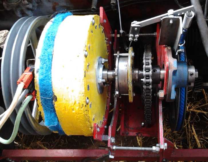 Before dark I
got the shaft and pulley from the car. I
removed the upper retaining clip, but found the lower one was quite
effective. It would have been a pain to remove and replace, so I cut it
off with the angle grinder to pull the pulley and shaft off. With a
bolt holding the shaft in, the clips were presumably superfluous. The
next day I drilled a hole in the center of the shaft on the lathe with
a center drill and then regular drills, and tapped it for 1/4" 20 TPI.
I cut a slot in a washer and put the whole thing on. This held it
firmly. (I worried about the bolt eventually unscrewing.)
Before dark I
got the shaft and pulley from the car. I
removed the upper retaining clip, but found the lower one was quite
effective. It would have been a pain to remove and replace, so I cut it
off with the angle grinder to pull the pulley and shaft off. With a
bolt holding the shaft in, the clips were presumably superfluous. The
next day I drilled a hole in the center of the shaft on the lathe with
a center drill and then regular drills, and tapped it for 1/4" 20 TPI.
I cut a slot in a washer and put the whole thing on. This held it
firmly. (I worried about the bolt eventually unscrewing.)
The results were disappointing. The car would hardly move.
If the rope slipped on the pulley, it just slipped without vehicle
motion. If it didn't slip much, the motor was overloaded. The rope soon
had smeared melt marks along it from getting too hot. (The original got
a few eventually, but nothing like this.) After trying a few
adjustments and not getting very far, the rope actually broke. The
previous arrangement, tho it had been limited to 20 foot-pounds, had
worked much better.
The first question now was,
why didn't it work? With a 2
to 1 speed-up instead of a 3 to 1 slow-down, it should according to my
theory now be turning faster and needing less torque. OTOH, the
slipping was now
on the wrong side of the 3 to 1 chain reduction from the motor, so 3
times slower and 3 times more torque. (Or is it 1.5 times slower since
its speed is doubled if the car isn't moving?) And being that the
torque converter was
the
differential, it wasn't possible to move it to the other side.
The second question, seeing it didn't seem to work, was:
what next? Seeing the original planetary gear did work, just not quite
well enough, I suppose that I should try other similar configurations.
Whether to spend 2000 or 2600 $ on one with my budget in hopes that it
might work better, seems a touchy point. In lieu of that, perhaps the
most practical ideas are to reconfigure the original gear and to try
the other planetary gear I got in the same Chrysler transmission gear
set.
If I turned the original planetary gear around, would it
be better as I had thought... or worse? It would of course take a lot
of rebuilding to reverse the planetary. But maybe not too much?
I could take the motor shaft with the sun gear on it and make that the
output shaft. A new motor shaft could drive the ring gear, with the
slipping pulley still on the planets assembly. On the other hand, the
sun gear was the fastest-turning one with the lowest torque to control
it. It seemed most logical that it should be the slipping gear.
A Missing Link
On the 14th, it occurred to me that instead of just having
the rope slip the pulley to a stop, it could instead connect back to
the motor
shaft. If the car wasn't moving, the differential's left side was
trying to spin 2/3 as fast as the motor. With some optimal pulley
ratio, instead of dragging and slowing things down, it would add its
derived force to the push of the motor, increasing the torque to itself
and to the wheel.
I had tried to think of ways to do this back in 2012,
but the output turned the opposite direction to the input, and it
seemed problematic to try and link them together. Likewise the slipping
gear turned more slowly than the motor/sun gear, and they were in-line
on one shaft. Unless the speed could be 'geared up' somehow in the
link, tying them together would still be little better than not. One
way would be to
put a generator on the slipping element and feed the generated voltage
back to the motor - the approach of Toyota Prius and Chevy Volt. It
would still take a bigger motor to make that
power, and my idea was the minimalist motor and components.
I had considered that the planetary gear acted like a
transistor, with a small force on one 'gate' element controlling large
forces flowing between the input and output elements. I discounted the
losses involved as being 'minor'. But the rope and pulley got pretty
warm in tests, suggesting that it didn't really work that way. I still
discounted them because they would decrease as a percentage of speed
until the rope didn't slip at higher speeds and lower torques. Now with
the differential gear heating up the rope until
it melted, I started to reconsider.
But now the differential gear, the slipping pulley and the
motor shaft - in fact, everything - turned the same direction. And
there were two shafts. A new
way for the torque converter to work started to
glimmer in my mind: If the force of the 'slipping' element
shaft was mechanically fed back to the driving shaft, the torque
would be multiplied based on the
speed of the motor and that of the car. I'll use 10 RPM per km/hour as
the
wheel speed for simplicity. (About right for typical 13" wheels.) Now,
if the rope is geared so it tries to
drive the motor at 1 to 1 speed when wheel RPM = Rope Pulley RPM =
Differential Center RPM (ie, geared up 3 times, to match the gearing
down of the chain drive), then, as long as the car speed (wheel RPM) is
below 1/3 of the motor speed, the previously wasted energy of the
slipping pulley is helping to speed up the motor, increasing its
torque. Now that seems more like it!
I entered some numbers into some tables to help visualize
the effect.
Vehicle Speed
(Km/Hr)
|
Driven Wheel
(RPM)
|
Motor Shaft
(RPM)
|
Differential Center
(RPM)
|
Differential Left
(RPM)
|
Slip/RPM Ratio
Diff.Left/Motor
(Pulleys geared 3:1)
|
0
|
0
|
300
|
100
|
200
|
2
|
10
|
100
|
300
|
100
|
100
|
1 (No slip)
|
20
|
200
|
300
|
100
|
0 (won't happen)
|
-2
|
|
|
|
|
|
|
0
|
0
|
1200
|
400
|
800
|
2
|
10
|
100
|
1200
|
400
|
700
|
1.75
|
20
|
200
|
1200
|
400
|
600
|
1.5
|
30
|
300
|
1200
|
400
|
500
|
1.25
|
40
|
400
|
1200
|
400
|
400
|
1 (No slip)
|
If instead the pulley and rope were geared to 6 to 1
instead of 3 to 1, a different range of values would be applied because
the slipping pulley would be pushing the motor until the wheel was
turning twice its speed.
Vehicle Speed
(Km/Hr)
|
Driven Wheel
(RPM)
|
Motor Shaft
(RPM)
|
Differential Center
(RPM)
|
Differential Left
(RPM)
|
Slip/RPM Ratio
Diff.Left/Motor
(Pulleys geared 6:1)
|
0
|
0
|
300
|
100
|
200
|
4
|
10
|
100
|
300
|
100
|
100
|
2
|
15
|
150
|
300
|
100
|
50
|
1 (No slip)
|
|
|
|
|
|
|
0
|
0
|
1200
|
400
|
800
|
4
|
10
|
100
|
1200
|
400
|
700
|
3.5
|
20
|
200
|
1200
|
400
|
600
|
3
|
30
|
300
|
1200
|
400
|
500
|
2.5
|
40
|
400
|
1200
|
400
|
400
|
2
|
50
|
500
|
1200
|
400
|
300
|
1.5
|
60
|
600
|
1200
|
400
|
200
|
1 (No slip)
|
It seems an odd sort of variable torque converter where the speed of
the car is directly proportional to the speed of the motor. But that's
"at speed", no slip. If the vehicle is below speed, the 'gear ratio'
has increased reduction for inceased torque. Or, put another way, at a
given vehicle speed, the motor will run faster and the pulley will slip
when more torque is needed.
If the pulleys were 1.5 to 1 increase to the motor shaft,
it would be 2 to 1 at the differential and the motor
would drive the shaft freely - the car wheel end wouldn't turn.
But what if the pulleys were less than 1.5 to 1? Then it would turn
backward, so the motor would be run in reverse. If the pulleys were 1
to 1:
Vehicle Speed
(Km/Hr)
|
Driven Wheel
(RPM) (Differ-
ential Right)
|
Motor Shaft
(RPM)
|
Differential Center
(RPM)
|
Differential Left
(RPM)
|
Slip/RPM Ratio
Diff.Left/Motor
(Pulleys geared 1:1)
|
0
|
0
|
-300
|
-100
|
-200
|
.67
|
10
|
100
|
-300
|
-100
|
-300
|
1 (No slip)
|
20
|
200
|
-300
|
-100
|
-400
|
1.33 (Won't happen)
|
|
|
|
|
|
|
0
|
0
|
-1200
|
-400
|
-800
|
.667
|
20
|
200
|
-1200
|
-400
|
-1000
|
.833
|
40
|
400
|
-1200
|
-400
|
-1200
|
1 (No slip)
|
Here we see lower ratios -
relatively high torque conversion - and also that the differential gear
will be
spinning like mad. Obviously there are
adjustments that can be played with in pulley
ratios to get different 'gear ratios' for different motor speeds. If
the torque increase was insufficient, the pulley could drive the motor
shaft at a ratio just slightly faster than the motor was in fact
turning, and the torque would be magnified more, with the driven wheel
speeding up with more force to a slower final non-slip RPM. The less
the pulley set gears up the speed, the more tension the rope can apply
to push the motor shaft faster, by however much or little added RPM.
I note that everything is turning the same direction, and
the free end
of the differential is spinning fastest. Hence, instead of connecting
it to
the motor shaft, one might instead tie it to the differential's center,
or
to the wheel end, with whatever reduction gearing seemed appropriate
for that element. However, the only easy place to connect it as it's
set up now
is to the extended motor shaft via pulleys.
Anyway, perhaps the originally mistaken concept about the
'low' losses acted as a bridge to help me to persevere until I saw a
more solid way through.
How to?
Adding the pulley set looked surprisingly simple: The
outer end of the upper drive shaft linked to the motor shaft almost
lined up with the slipping pulley I had just put on. If I simply moved
the pulley out a couple of inches on that shaft I hadn't chopped the
end off of "to allow future options?", they would be in line. The 12"
pulley would be too big, so it would be a matter of buying some new
pulleys and "H" taper-lock shaft bushings for them. I might have to
turn out the center on one to a metric size again. A troublesome aspect
is that the pull will be to the side, and the shaft is only supported
at one end, in the differential. I'll probably have to add a support
bracket and outside bearing.
Then the rope would doubtless need an idler pulley and
spring, and perhaps one for each direction. Then again, why was I using
a
rope? Why not a flat belt? I still had the poly-V belt I bought. It
would pass for flat, and it was
about the right length. The only downside would be finding pulleys. But
flat belt pulleys can be made on a lathe! Plus, I had the two 6"
pulleys I already made on the 3D printer quite a long time back. That
would give the ratios in table 3. It might be worth connecting them
because that should certainly drive the car, easily, at "in the yard"
testing speeds. I can change them later. And I'll see if they just fall
apart. Now about that unsupported shaft...
When one has pre-made parts not made for one's purpose,
they never fit what you want to do. You have to adapt by making your
own parts. When I went to put a pulley on the lower shaft, I got a
splined piece from the transmission. It fit perfectly onto the splines
on the shaft at about the right place to line up with the upper pulley.
To my great surprise, its outer splines meshed perfectly with the 3
bolts meant to hold the pulley onto an SDS taper-lock shaft bushing,
holding the pulley centered and preventing it from slipping around the
shaft. If I took long bolts, I could take a large washer and drill 3
holes, slip it over and put nuts on. I got the bolts... then instead of
a huge washer I found an SDS bushing for a 2" shaft. It fit right over
everything and the pulley bolted solidly into place via its three
pre-threaded holes. WOW! It was virtually as if everything from two
totally different sets of parts had been made to fit together. The
shaft sagged a bit, and if pulled up came about level. Since the belt
would pull it up, I decided it could do for testing without adding the
support. That was one major piece of a custom assembly, ready to go in
an hour! Remaining were the top pulley and the idler wheel for the
center of the belt, which would be attached to the gearshift lever for
the variable slip.
For the top pulley I found a big 3/16" steel ring just
slightly too large to fit. I turned it down to fit in the lathe. Then I
drilled holes to line up with those in the pulley to attach it with.
These were also useful to mount the pulley on a backing plate for the
lathe, which allowed me to center it, tighten the bolts, and turn out
the inside diameter to fit a 1" I.D. SDS bushing. (My 3-jaw chuck
wasn't big enough to grab it by the outside edge.) I almost turned it
out too large - you mill and mill and mill, and it takes so long to get
near the right size, and suddenly it's past it. But it still fit on the
bushing (almost at the fat end) and tightened it onto the 1" shaft from
the motor.
I dug out the old idler wheel I had made to go with these
pulleys. (Wow, I found it!) Then I spent 10 days doing Turquoise
Energy's annual taxes.
I was sure the pulleys would need sides to ensure the belt
didn't slip off the side. In theory the slightly convex face keeps the
belt centered, but with a slipping belt, the forces may be less
favorable than with one that doesn't. On the 25th I got some 3/8" thick
scrap aluminum pieces from AGO to make the sides from. I checked and it
looked like there was indeed room for such thick pieces.
Jim said to make the center hole with a hole saw, cut off
the corners on the bandsaw, and turn the outside on the lathe. I
figured, if I was going to use such thick pieces and turn them, I could
also shape the insides of the rims so they would guide the belt but not
bind, and so that the belt would always touch against rounded edges and
not a sharp outer edge. Even if the 3D-printed pulleys fell apart, I
could still make new pulleys and use these same edge pieces - as long
as I didn't change the pulley size. I bought some hole saws that
afternoon... and a 12" combo sheet metal shear, bender and roller that
I saw, for 280$. I had almost bought one of those about 15 years ago
for 189$, regretted ever since not having done so whenever I worked
with sheet metal, and had never seen another one before. Aside from the
shopping, I still didn't have any time to work on it until the 29th,
and I only got a bit done, and then was diverted again.Hopfully I'll
have it together and tested in July.
The pulleys on the differential's left 'drive'
shaft and on the motor shaft.
Behind is the idler wheel, and an aluminum circle cut to be one of the
four end plates for the pulleys to retain the belt. (The motor is just
sitting there, not connected or in place. The yellow plate clamps the
planetary gear ring and planets together so it will simply act as a
coupler.)
Yet Another
Possible New Type of Variable Torque Converter
(The "Double Barrel Torque Converter"?)
As I considered yet again possible alternatives for making
a variable torque converter, I came up with this idea, which just might
be practical.
Some converters use a belt and two split "V" pulleys. The
sides of the pulleys can be moved in or out to vary the width of the
"V", oppositely to each other, to vary the effective diameter of the
pulley against the fixed width belt. This is used in a few cars, where
it requires quite a rigid metal segment "V-belt". Lightweight versions
with regular V-belts are used in snowmobiles and small motorbikes. I
have a hard time thinking it's very efficient. (But I don't have any
figures for it.)
Another one like it has more of a flat belt and two
opposite cone shaped pulleys. The belt can be moved toward one side or
the other, again reducing one diameter and increasing the other. This
one requires the belt to deform side to side as it turns in addition to
having the flat face wrapping around the pulleys. I doubt the efficacy
of the system and I haven't seen it in use. A demo one I saw on youtube
took up quite a lot of space.
Of course one can't use gears or toothed sprockets in any
such variable system, because in varying the sizes there are places
where they just won't match up. A sprocket or chain can't have 21.5
teeth. So it
has to be some sort of traction type arrangement. If it is employed
before a final gearing down to car wheels, hence at a higher RPM and
lower torque, a reasonably small flat belt on 'sticky' (as opposed to
'slippery') pulleys stands a good chance of having sufficient traction.
If one had a relatively (3"?) wide flat
drive belt, instead of a round pulley, it could turn on something like
a wooden barrel with 'boards' or 'staves' running across it from one
end to the
other. If those staves were expanded outward, the
flexible flat belt would still run around it even tho there would then
be gaps between them and the drum would be (eg) a hexagon instead of
round. The belt would link to another 'barrel'
with expanding boards that contracts and expands oppositely.
I can think of a couple of basic ways to do this, but
since I have no plans for building one at this time, I'll leave the
mechanics to the imagination except to note it could work manually, or
automatically.
For automatic, as the input shaft speeds up, its barrel
would expand by centrifugal force, and increasing belt tension would
force the output barrel to contract. So as the motor speeds up, the
'gear' reduction would decrease, and vice versa. In this case the
staves on the output barrel would be spring loaded to spring outward,
and would be forced inward as the input pulley expands. These springs
would also set the belt tension.
Once again, if a flat belt isn't slipping, its drive is
said to be almost 99% efficient. The belt has to be wide enough and the
coupling 'boards' in total broad enough with traction enough that it
doesn't slip at any expansion or contraction positions. A wider belt
will work with smaller pulleys and vice versa. Probably a good
arrangement of such pulleys and belt wouldn't take up any more space
than, eg, the split pulleys type of converter. It would need no oil and
so could simply be under a cover to keep dust out, and hence the belt
or drums could be easily replaced.
http://www.TurquoiseEnergy.com
Victoria BC Canada