Turquoise
Energy Ltd. News #102
covering July 2016 (posted August 1st 2016)
Victoria BC
by Craig Carmichael
www.TurquoiseEnergy.com
= www.ElectricCaik.com
= www.ElectricHubcap.com
= www.ElectricWeel.com
Month In Brief
(Project Summaries)
- Sprint/Variable Transmission - Ocean Wave Power - New Chemistry
Batteries (Air-Nickel) - Solar Panels for
the Miles Electric Truck? - Hydro Power from
Small Creek on the Cheap (a Video)
In Passing
(Miscellaneous topics, editorial comments & opinionated rants)
- Rising Sea Levels? Not so fast! - Platinum Gets Rare - Turkey
Shoot - Violence Starts with Ruthless People - More
Lawlessness - Where are the VHE/Lambda Ray/"free energy"
Collectors/Converters?
- In Depth
Project Reports -
Electric
Transport - Electric Hubcap Motor Systems
* Electric Hubcap motor, Chevy Sprint & Variable Transmission:
Other "Green"
Electric Equipment Projects (no reports)
Electricity Generation
* Solar Panels for the Miles Electric Truck?
* Oscillating Water Column (OWC) Ocean Wave Power Buoy Drawings
Electricity Storage - Turquoise Battery
Project (NiMn, NiNi, O2-Ni), etc. (no reports - see month in
brief)
July in Brief
Sprint/Variable Transmission
As in June, most of the month's project work that I
managed to get done, which wasn't very much, was on the variable torque
converter for the Chevy Sprint.
After not getting the last newsletter off until July 8th,
it was another couple of days before I finally got a bit of project
work done: part of one of the pulley sides. By the 14th in spite of
minor challenges I had two sides done and the lower pulley together,
and on the 15th and 16th I did the other one. Shaping the sides on the
lathe and cutting the bolt holes and getting everything to line
up occupied
considerable time.
Then the drive shaft wasn't quite long enough as I already
knew, and when I
finally tried to test the system, the pulley came off the end. There
was nothing for it but to make a new shaft. I also got 'joy' couplers
to connect the motor to this shaft, and I had to cut the sun gear off
the motor shaft. I was very reluctant to do this, but nothing else
worked, and I was even more reluctant to disassemble the motor so I
could press it off in the hydraulic press or replace the whole shaft.
Since the drive shaft was now connected to the motor at one end, it
should only have a single "steady" bearing at the other, so I took off
the cut-down trailer wheel hub with its two bearings and replaced it
with a single press-fit mounted needle bearing. Luckily I saw how to
mount it very easily with the same bolts as the hub, just by grinding
and filing the outside edge a little so it became an exact, locked in
fit.
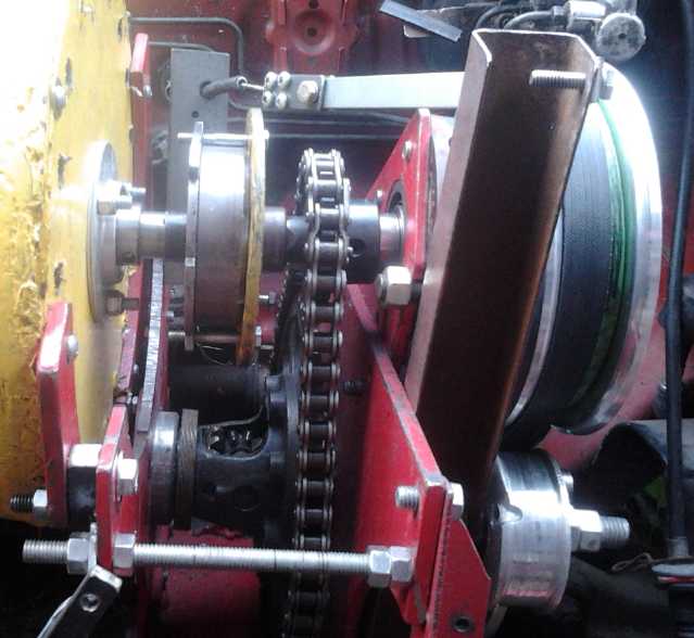
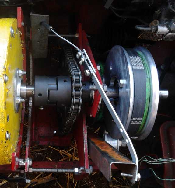 L to R on shaft: Motor, Joy (flexible)
coupling, chain drive to differential
L to R on shaft: Motor, Joy (flexible)
coupling, chain drive to differential
center, needle bearing, slip-belt pulley to differential left (port)
side.
Idler pulley is seen below, mounted on steel "U" arm, with hinge pin
at the bottom and tensioner from shift cable at the top of the arm.
When I finally had it all together, testing didn't go
well. The thin steel "U" piece I'd used to mount the idler pulley, tho
just the right size, flexed a bit and the idler didn't get a lot of
tension. When it got enough, the 'poly-V' belt melted poly-V
grooves into the ABS pulleys. The belt was pretty warm and I could
smell the hot plastic. I turned the belt inside out with the flat face
against the pulleys. It took so much pressure on the belt to force it
to engage that I ran a bungey cord to the driver's door and pulled on
that as well. Then the adjustment screw in a slot, strongly tightened,
slipped and the belt slackened. Later I noticed that the smooth face of
the belt was also quite slippery compared to the textured poly-V
face.
In all the testing, the car moved: only backward, 3 or 4
times, a foot or two, and only if it started from a position where it
wouldn't
take much of a push to start it going. I wondered if the reduction
ratio was sufficient even with the slipping belt, but I wasn't really
sure it ever got a fair test, either. And it seemed the idler would
have to be on the back side instead of the front to drive forward. Two
idlers?
On the 30th I went to Princess Auto to get another idler
pulley to install on the back side. I noticed they had a wide, fat belt
from a variable torque converter such as is used on small motorbikes.
I thought that if a fat belt like that would grab at the
edges of the pulleys like a big V-belt, it should take far less
force to get sufficient friction for things to engage as desired.
Finding such a belt was another problem - theirs was too short. I
started thinking of somehow using multiple strands of rope to create a
wide belt. Or maybe single ropes in double V-belt pulleys? What, change
the pulleys back to V-belt?!? Or maybe a couple of layers of PP
webbing/strapping the full width of the pulleys?
Ocean Wave Power
In saying what project I actually worked on, I can't omit
a thing I actually spent far more time on: considering ocean wave
power
and discussing it with potential funders and participants in Australia.
Someone pointed us to Wikipedia, an obvious source of information we
all should have thought to check earlier but of course didn't.
That made me think of youtube, and I started watching
videos. At first, my contention that the rope and pulley system with
all the floats tied into a tower on the shoreline was better than one
done with hydraulics seemed to be gaining sway. Then I found a video
about a floating machine using the oscillating water column (OWC)
method of extracting the energy. I had long ago heard about the one in
Scotland - a big cement structure on a steep bank - and I thought (ie,
without thinking) they had to be made like that.
Seeing the floating one revolutionized my thinking. Large,
heavy floats are ponderous. It takes time to get them moving. If the
waves are large that's okay, and large floats can extract more energy,
but if the waves are too small large floats won't move much to extract
even what energy they have. A water column in an open bottom tube buoy
reverses this inertia problem, immediately rising or falling with each
wave of whatever size, and exhaling or inhaling air through an air turbine covering a hole at the
top of the tube. It can extract the max from small or mediums waves,
but will start to follow large ones up and down, reducing stress in
storms. I drew 3 diagrams and sent them to the group. I've included
them in the "detailed report", which actually has just the drawings.
Someone else did a presentation in LA, CA, USA about wave
machines in general and what crappy designs there were out there (eye
opening in itself), and then showed his version of a floating OWC
machine, and how it would generate electricity for 2¢/KWH. It was
different in that it used a water turbine rather than air, in a venturi
under the water column's surface.
At first I thought this might be as
good as or better than the air turbine. Then I thought it wouldn't.
Then I realized it was his buoy design I didn't agree with, and decided
that if the buoys were similar, its performance would also be pretty
similar. (depending on relative turbine setup and efficiency.) But
moving parts
under the sea would corrode faster, and furthermore, a single air
turbine-generator unit could be more easily unbolted from the top of a
buoy and removed for servicing. So I went
back to thinking the air turbine was the better idea.
If he continued his experiments he would probably come up
with good units. But like most of us
working in green energy, he ended by saying he needed money to get any
farther. Big oil and even (now totally uneconomical) nuclear energy get
subsidies. Green energy gets the
cold shoulder or even sabotaged. (How did we ever even get river hydro?)
The air turbine model too (as I visualize it) needs mass
if it is free-floating, but in this case we don't want it to
rise and fall, so it works the other way, reducing power output
efficiency as the waves get bigger, while making the most out of the
small ones. I think that's the way to get the most and steadiest power,
including during those many calmer months when swells are a meter or
two instead of 3, 4, 5 meters or more. The motions it does make *might*
actually be helpful in amplifying wave effects. I could see it getting
up to 3 times as much average power over a year as non-OWC systems.
At both ends of the Pacific, we figured that 'politics'
and 'bureaucracy'
was probably going to be a harder problem than the actual project. I
was sorry
to hear it sounding like Australia would be as bad as Canada.
The first wave power unit to actually go on the European
power grid is one mounted on a wharf in Gibraltar. Another that is said
to
be going on line next year is in Denmark. Note these places: the
decisions permitting the projects were doubtless made locally. In
larger countries, the entire shoreline is government property and
bureaucracy makes everything so difficult
that no one can get anywhere, so the first success was Gibraltar rather
than Germany, France, Britain or Spain, with all the resources any of
these
could potentially throw at it. And as I may have said in 2008 in some
of the first issues of TE News, trying to get anywhere with anybody
here in BC seemed like rowing up a waterfall.
There are no little countries or duchies in North America
nor in
Australia where one might skirt the big bureaucracies. But there are a
few little out of the way islands and isloated places. I'll leave that
thought for now.
On the 24th a news article about making drone engines with
3D printers in Russia reminded me of that process. Maybe I could more
easily make the smallest wave power turbines for testing buoys - and
for comparing turbine types - from
plastic on the
3D printer? I continued to think of cutting the bottom off an old hot
water tank, and cutting a square wind hole in the top and outfitting it
to be a wave power buoy. I would cut pieces of 2" styrene foam as
floatation and glue it on with canned spray foam - a technique I
learned while making the peltier module fridge.
On the 29th I went out to the garage and tracked down a 24
volt lawnmower motor I mentioned many newsletters ago as a potential
low power generator. That might handle what the water tank can put out.
For more power I'll have to either sacrifice my 12 amp, 120 volt mower
(I loaned out the other one - sigh!) or else convert an alternator to
permanent magnet armature.
On the 31st I looked for "air flow turbines" and finding
nothing for sale, ended up reading about OWC design and theory on the
web, complete with all the funny greek symbols in complex equations. I
started to think that a "common sense" estimate of everything might
work out just as well as getting lost in a maze of formulae.
On August 1st I ground the welds off my 2007-8 attempt at
wave power, lurking in the bushes in a corner of the yard for nearly a
decade, to liberate the two rusty old hot water tanks. Now each tank,
all by itself (with hanging weight, foam floatation, and a turbine and
generator on top) could be its own wave power unit that would doubtless
capture more energy than the entire 2007 unit that included both tanks,
welded joiners and various mechanical parts and supporting stucture.
 2007-8 wave power attempt; rusty water tank:
Cut off bottom and outfit as
a wave power buoy?
2007-8 wave power attempt; rusty water tank:
Cut off bottom and outfit as
a wave power buoy?
Much was made of the need for airflow turbines/fans that
would turn the same direction with air coming from either direction.
The standard seemed to be the Wells turbine, but a youtube video
compared that to a modified wells turbine with blades that flipped
back and forth
depending on the air direction, which seemed to perform much better.
But even that isn't the optimum wing/propeller airfoil shape. I struck
me as the wrong approach. I think
it might be better to use one-way louvers or flaps so that the air
always hits the turbine from the same direction, regardless of whether
it's going into or out of the buoy, and make an optimum turbine.
A 'DIY turbine' in a youtube video reminded me of computer
fans. I got out my largest one (120x120mm), 48v @ .15a or 7.2 watts.
Spinning it with the vacuum cleaner on "blow" I got (aside from some
funny and inconsistent much higher voltage readings) about 7v o/c and
.06A s/c. for a maximum possible .42 watts. That could light a bright
LED. I think that would make a disappointing demo. On the other hand,
one facing each way, each with a flap, seemed a simple solution to the
bidirectional flow dilemma.
New Chemistry Batteries - Air-Nickel
On the 19th I stuck the nickel-air cell (now sitting on
the counter for about 2 months) into a jar of water. I pulled it out to
drain and changed the water, several times over several days, to
hopefully dissolve out impurities. All that beeswax that seemed so
sticky came loose all the way around the edges. And the top bulged up
like a big bubble. And then I started cleaning up the
counter instead of working in a mess... and didn't get any
farther. Sigh!
Solar Panels for the Miles Electric Truck?
I started driving the truck more in July. Where it had
been able to do 30 MPH with the original bad or intermittent motor
rotation sensor, after the repair it would only do 25. Ugh! So I stick
to short very local
trips. The puzzling thing is the Miles vehicles are supposed to be
fully road safety rated, so why are their electric ones, only, with the
same frame and cab as the gas ones, deliberately so limited
in speed?
I had been
thinking of using two 90 watt solar panels in series as a possible
charging system for the 36 volt Sprint. The maximum open circuit
voltage per the specs is 22.3, so two would be 44.6 - theoretically
enough for a 42 volt float charge on 36 volts NiMH.
 The
truck is 72
volts. On the 23rd I set the two panels on the truck and measured about
39 volts.
For charging a 36 volt segment, that would be 13 volts per 12
volt section - a good minimum float charge voltage for lead-acid. 1/2
of the batteries initially measured 38.3 volts. Clouds came on and off,
and the charging current varied between 50mA
and 330mA; at one point .4 amps. The panel will supply about 3 or 4
amps (4.9A at
MaxPowerPoint) if the batteries need charging.
The
truck is 72
volts. On the 23rd I set the two panels on the truck and measured about
39 volts.
For charging a 36 volt segment, that would be 13 volts per 12
volt section - a good minimum float charge voltage for lead-acid. 1/2
of the batteries initially measured 38.3 volts. Clouds came on and off,
and the charging current varied between 50mA
and 330mA; at one point .4 amps. The panel will supply about 3 or 4
amps (4.9A at
MaxPowerPoint) if the batteries need charging.
After 20 minutes the voltage was 38.6. But an isolating
diode is needed to prevent the batteries feeding back into the panels
when their voltage is lower (ie, no sunlight). And as panels warm up,
their voltage drops a few volts. With them already marginal, I begrudge
another 1/2 a volt diode drop loss.
After considering various "almost works" choices, I
decided
maybe the best solution (and only since they are
6V lead-acid batteries) would be to use the four 90 watt panels as four
18v
charging sections, and design my own oscillator circuit to drive some
switching
mosfets, to switch the connection (the minus side) on and off at high
speed to give "pulse
charging", which will automatically weaken to "not much" as the
batteries reach full charge... if it's sunny... in the summer. This
would
also incorporate a
shutoff for when the panel voltage is less than the battery voltage.
And the mosfets would act as "active rectifiers" without the loss of
over 1/2 a volt for passive diodes.
The real voltage from the panels is a little too low to
float
charge NiMH. The Sprint with NiMH and or lithium cells will need
another plan.
---
Then I think in the cab I should put four 18 volt meters
on the dash to show the state of the battery charges of each section.
If a battery is dying, one can isolate it to one of the four
sections and replace those 3 - and keep the two still good ones
for the next dud, maximizing use of every battery and keeping cost
down. The immediate problem with that is that the present batteries are
only 180 amp-hours instead of the usual 220-260 amp-hours of most 'golf
cart' batteries. New ones with more capacity will upset balance
when charging from 120 volts, and one might want to replace the lot to
increase range anyway.
Hydro Power from Small Creek on the Cheap - Video
I've watched this video a couple of times now: Water
Wheel
Generator by Off Road/Off Grid youtube channel. With a
very small creek, a chute of a few boards, a big old wire drum/spool
made
into a water wheel, a bicycle wheel as a big pulley and an alternator
converted to a permanent magnet armature, this fellow has made a hydro
power plant for his country mobile home. With a very low head, it puts
out about 40 volts and is probably well under 100 watts if not under 50
(he didn't say -
maybe he doesn't really know, and of course it would vary with water
flow in the creek). But of course it runs continuously, which is better
than most alternative energy sources.
He uses it with a modified charge controller to charge
some old 12 volt batteries. The batteries feed a 1000 watt inverter.
Thus when he wants power, even hundreds of watts for a while, he has
it, and recharging starts as soon as the load is turned off.
I got a call from AGO on the 27th. They finally had
all the parts to make more ships' winches slip rings, and needed two
made ASAP. Considering how little I'd got done in July on projects, I
figured that would probably pretty much end the month. Ah well, a
little extra income doesn't hurt! Anyway, I didn't get them finished
before the August 1st long weekend, and I did do a bit more project
work.
For August I hope to do a bit more variety of work than
just the variable transmission, whether it's battery development, wave
buoy construction, or just the solar panels for the truck.
In Passing
(Miscellaneous topics, editorial comments & opinionated rants)
Rising Sea Levels? Not so fast!
Last winter I wrote of unusually high water levels which
several times flooded the lowest parts of the sea walkway near my house
at high tide. Such flooding had only occurred once before, perhaps a
decade previously. I took this to mean the expected rise in sea levels
had become perceptible. However, these episodes weren't repeated and
there have been some pretty low tides this summer. Then I heard that
ocean levels have risen by only about 2cm - less than an inch. NOAA has
this to say: "Since 1992, new methods of satellite altimetry (the
measurement of elevation or altitude) indicate a rate of rise of
3 millimeters or 0.12 inches per year." This figure
indicates a rise of nearly 3" from 1992 to 2016. Not huge, but not
insignificant, either.
On top of the 3", the extra high waters here last winter
may have been a combination of factors which would have included El
Niño, heavy rainfall on the mainland gushing out the Fraser
River mouth, and "super moon" especially high tides.
The 3" however is sure to continue growing.
Platinum Gets Rare
Okay, so you already knew it was rare. Until the last 3 or
4 years, for decades platinum has cost substantially more than gold,
even double. Now it's substantially less. Like gold and silver it's
considered a monetary metal so there's no sales tax. I decided to buy
some platinum since it'll probably revert to its usual higher price as
the manipulations end and all the precious metals rise.
I have been having a bit of trouble getting it. I ordered
a bar and it came immediately. I ordered another one later, and it took
almost a month, with the usually prompt supplier (SilverGoldBull.ca)
eventually e-mailing and apologizing for the delay. On the phone, a
lady said a shipment they had expected didn't arrive and they had
run out. It was perhaps "on allocation". (limited quantities to
dealers) There have been times platinum (and sometimes palladium)
simply isn't on the shopping list at on-line dealers - as was again the
case for the platinum bars for a while before my order arrived. I've
never
found any locally.
Demand for gold and silver are continually rising as
people lose trust in paper money and blips on banks' computer screens
(conjured up out of thin air). Soon they too will be more in demand
than there is stored metal plus new supply, and there will be waiting
times and the prices rises already happening will accelerate.
A diminution of precious metal price
subsidization started to happen in June. By August 1st platinum
(retail 1 ozt bars) cost 1600 $Canadian versus 1330 $ in mid June. The
western world's
vaults are said to be about empty, and the scheme can't be continued
without at least some real metal backing the unbelievable amount of
paper futures contracts for metals that will never be delivered. (I'm
sure the guards at Fort Knox are only there to prevent anyone from
finding out!) Why are they doing it? Because if gold and silver were
continually rising in price in a free market, the decline in purchasing
power of fiat currency would become more glaringly evident than it is
at the grocery store. Then many people would start buying metals
as
a hedge against inflation, accelerating its fall. Now they can't hold
the beachball under the water much longer. (While precious metals have
gone down since 2011, people are telling
me unbidden they are paying double for food what they were a couple of
years ago. Surely it isn't that bad yet, is it? I'll get there and
more... but whoa!, I covered that last issue.)
Turkey Shoot
The attempted coup in Turkey was apparently fomented by
the CIA and other American/corporate/financial interests. A Turkish
woman living in the USA predicted on Corbett Report many months
previously that she expected the CIA to attempt such a coup.
The plan apparently was to kill Erdogan, get rid of the
Turkish prime minister and parliament, and install the
ultra-influential Moslem guy living in Pennsylvania as a dictator. (I
forget his name - he was already wanted in Turkey before the CIA
spirited him out of the country.)
Omitted in the media demonization of Erdogan with much
groundless name slinging like "tin pot dictatorship" and then how
"Erdogan" was maltreating thousands those involved in the failed coup
and that he was bringing back the death penalty for them, has been that
he was democratically elected by the people of Turkey. So was the
parliament. The justice department of Turkey is the body rounding up
the coupsters and those involved in groups which had been known for
some time as having violent anti-government leanings. True, Erdogan
said in an exclusive Eljazeera interview (youtube) that if parliament
passed a bill to bring back the death penalty, as was being demanded by
the people, he would sign it.
The coup was timed for the middle of the night when
everyone would be asleep, and by morning when everyone woke up, it was
supposed to all be over - fait accompli. Some factors that led to
its failure: Erdogan got warning in time to be elsewhere than his hotel
room when they stormed it to kill him, and likewise to warn others in
the government. Social media spread news quickly that something was
happening. (Also spreading lies that Erdogan had fled the country and
the coup had succeeded.) Erdogan asked the citizens of Turkey to go out
in the middle of the night and occupy the town squares and government
buildings. This they did, even climbing onto tanks, and 270 lost their
lives. The police went out and arrested many of the military
participants - even tho these were wielding powerful military assault
weapons which they could not match. (Many of the military were told
they were simply taking part in an "exercise".) All these courageous
acts indicate that people prefer an at least nominally democratic
government to a dictator installed by a foreign coup, a process that
doesn't seem to have worked out very well for the people of Ukraine.
Violence Starts with Ruthless People
In the USA lately, some policemen shoot innocent people
and are acquitted. In fact, there have been more annual
gun
deaths by the police in the last 2 or 3 years than by everyone else put
together, and more robberies by the police from persons or from
vehicles ("redistribution of wealth"
or "civil forfeiture") than by everyone else.
Then we have the topper: After a chief witness against
Hillary Clinton, no less than a former Secretary General of the UN,
turned up dead with his throat crushed (they tried to say it was a
heart attack, but the real cause got out - now it's "from exercise
weights in his gym"... let's see: he was weak enough to be in danger of
a heart attack, but he was exercising with crushing weights?), the
head of the FBI read off
a litany of her crimes as Secretary of State on TV... and he ended up
by saying she won't be charged (but he said that if you try the same
things, you will be). He carefully phrased things to leave out typical
incriminating words, such as saying "reckless" instead of
"criminally negligent". Perhaps he and his family were
threatened. Likewise, Attorney General Loretta Lynch, after meeting
"secretly" (it got out) with Bill Clinton, pursued no charges.
It is now plain to all that rule of law is dead at all
levels, and that even the biggest predators - especially the biggest
predators - are free to continue their predations.
A result this summer is a growing struggle
between those most oppressed and the authority of the state as embodied
in its increasingly corrupt police forces. Caught in the middle are
society at large as well as the good police, who will be targeted just
as much as the bad just for wearing their uniforms.
Many Americans are pointing to this as "The Day the
Republic Died." Some say "Republic" now has to be preceded by "Banana".
But it has been in decline for over a century. I might rather point to
November 1963 when president John F Kennedy was shot and killed.
Kennedy was a beacon of hope to a nation that had already been
increasingly darkened for decades by private and corporate agendas that
went against the public good. He tried to eliminate government secrecy
and corruption, harness tidal power for virtually free energy, have the
US treasury print money directly instead of via the private "Federal
Reserve", stay out of wars and disband the CIA, and expose hidden
agendas, and for these things he was hated by most every special
interest group. Only the public loved him, and that wasn't enough
support.
Since Kennedy, corrupt private interests have seen to it
that no such president was ever again elected, including by murdering
his brother Bobby in 1968 when he tried to run for the office. Hope for
a brighter future died with the Kennedys. The last vestiges of real
public control over national affairs were dead.
Of course, my own ideas on how to take back full control
of our affairs are at http://www.HandsOnDemocracy.org
. It wouldn't be that hard if people were awake and realized that they
can't simply hand over their own political power and authority to
others, avert their gaze from the political "black box" machine for
four years, and expect good results. The internet can be a powerful
tool
for making sure that what goes on in government is known publicly
and is what people really want to have happen, and that people who
wish to serve rather than to rule can be chosen for public offices.
We are today seeing that when ruthless predators are
allowed to run amok, not only does it make things worse for everyone,
but that society eventually cannot survive at all. In the future, if we
are to have socially sustainable societies, we must have the temerity,
audacity and nerve to stand up to ruthless people who prey on the
innocent when once we recognize their crimes as such -
people like the original Rothschilds, the David Rockefellers,
the JP Morgans, the Alfred Sloans, some of the 'big oil' and bank
executives, the Clintons, probably many or even most of the 65 people
who have as much wealth as half the planet's population, and, well, the
list could go on and on and on. We will need to arrest such people, try
them
fairly and impartially by a judgment group, and execute the guilty,
rather than have them return to society at any later time to take
revenge and resume their manipulations, robberies, abuse and killings
so many unsuspecting souls, and to continually decimate our most
progressive social, intellectual and creative elites when they try to
make progressive changes. They sideline progress, generation after
generation, nowhere more than in energy, finance and governing
institutions.
The "mainstream" media is on their side - paid lackeys,
who will lose their jobs or their broadcasting licenses to 'go against
the narrative'. They demonize those the corrupt don't like with lie
after lie. One would believe from the "mainstream" news that Trump,
Putin, Assad, Erdogan and others are the most evil of people. I have
heard people say that if Donald Trump is elected, he'd start World War
Three. Really??? The man who said Putin is a great leader, and that he
could work with him? It is in fact Hillary Clinton who said that a
nuclear first strike against Russia is not off the table. So by
their own words: Is it Trump who is likely to start world war
three? Putin himself praised Trump in return, and warned that if
Clinton
is elected, the world is headed towards war, and (to
western reporters) "It really worries me that you seem insensible to
the
danger."
Another person said "Don't let them undermine or
federalize your county sheriff's office." In the USA sheriffs are
elected and are not accountable to those in any other political office,
only to the public by election. They represent only the enforcement of
law and order. This was a brilliant move on the part of whoever set it
up. The sheriffs may soon be the only people standing between civilized
society and slavery or civil war, anarchy. If or when the time
comes, when the crimes are seen to have caused a horrendous economic
collapse, the local sheriffs are not employees hired by the rest of
government. The politicians don't have authority to give them orders or
to fire them. They will have the authority to arrest all these corrupt
politicians and all their corrupt associates - lawyers, judges,
bankers, anyone - and lock them up pending trials.
When the old system has definitely failed and everyone is
looking for answers, they will be ready to try out ideas like Hands On
Democracy, and to build socially sustaining communities embodying the
six core values of Quality of Life, Growth, Equality, Compassion,
Empathy and Love, starting at the local level.
More Lawlessness?
Here is some heresay from a video on youtube. I think
I mentioned a while ago that police in the
USA have been searching cars and relieving people of any cash they find
- "Prove it wasn't drug money." or some such nonsense.
Now (it says) Oklahoma has apparently
carried the program to a whole new level. The video I saw said they
have devices that will
scan your debit card and prepaid credit cards and take the credit or
the money from your back account. However, if they are real, I haven't
heard any stories
of them being used for such theft - yet.
This source thinks law enforcement are stealing a
hundred billion
dollars a year now from innocent motorists who will never be charged
with a crime, but who have nonetheless been relieved of their money by
highwaymen, er, highway patrols. Evidently truck drivers are a
particular target because they may have large expenses, and hence carry
more cash. (I used to hear tales of Mexican
police wanting $20 if they pulled over a "rich American tourist". They
were being modest and polite!)
The same video also says the federal government got
scared by how much they were "raking in" and quit, but now many
desperate states are in on the game. (And
here I thought it was just crooked cops!)
Whoever is behind it and however widespread it is and
however much is being taken, the CBC news, usually a pretty reliable
source, warned Canadians traveling to the USA about the robberies a
couple of years ago, with a couple of disturbing motorists' tales of
losing, for example, the money given a student by his parents to go to
university with. If more and more people hear
tales from people in their circles about being robbed by police,
doubtless many more
Americans likewise will start fearing to go on the road -- especially
truck
drivers, even out of proportion to the amounts stolen. Ultimately that
can only lead to the breakdown of the delivery system and social order
as a whole. Unless all this isn't true,
in
a culture of increasing lawlessness there are doubtless those who will
now flee from the police just because they're carrying their
own money -- and
perhaps some who will open fire on them if they can't get away.
Civilization is built on rule of law and trust that that law is
properly and
equally applied to all. How can it possibly survive
such an onslaught? Look for new stories of high speed police chases
and be sure to wonder why the 'suspect' was fleeing from police.
Where are the VHE/Lambda Ray Collectors/Converters?
I have written about VHE (Very High Energy) or (as I
called them) "Lambda" rays, recently at last identified beyond the
gamma ray spectrum, and theory for how to turn them into electricity.
Others have made these exciting and astounding discoveries long before,
even without having the whole theory. I have written how in some of
Steven Mark's last e-mails he said he was being threatened by the US
government with jail if he didn't shut up about it. (Yes, they had all
his e-mails - spying without a warrant. Think government spying is
benign or is used against "terrorists"?)
Then there were the two people in Brazil who had Brazilian
patents for free energy devices, did a youtube video about them and
offered to sell them locally, and who then vanished from the radar
screen, after having been arrested once on trumped up charges and then
released.
I don't watch "Dragon's Den", and can count on 2 or 3
fingers the number of pitches I've seen. But one of those, as I channel
surfed by, definitely caught my attention. Someone brought in a free
energy device, placed it on the floor, and turned on some incandescent
light bulbs powered by it. He said something to the effect that there
were no batteries in it and that the light bulbs would stay lit as long
as anybody wanted.
It was quite a short presentation. After a few moments,
one of the "dragons" jumped up, walked over and shook his hand, and
said "If the technology works, I'm in." As usual, rather than changing
the world, that was the first and the last I ever heard of that.
A Malaysian Airlines plane (called 'Flight MH370' IIRC)
disappeared over the ocean some time later. It suddenly and
mysteriously vanished with no distress call and it was never found...
but it seems a damaged piece of the elevator appeared a year or two
later on an island in the Indian Ocean. I hardly remember the details,
but it seems to me some thought some dents or holes indicated a bomb
had gone off on the plane.
It's somewhat 'common knowledge' that when those in the
top positions of power and influence want to get rid of someone, a
plane crash is sometimes used. That anyone having wealth and influence
could be so evil, so utterly lacking in conscience and moral nature, as
to sacrifice a whole plane full of innocent people to kill one innocent
person they don't like stretches most peoples' credulity, and so his
death would have to be seen as an unfortunate accident, not as a
targeted killing. Yet, "collateral damage" - violent death of multiple
innocent people in pursuit of a violent agenda - appears to be quite
acceptable in some circles. A bomb on a plane? Well then, it must have
been terrorists.
I heard a rumor shortly after the crash that there was a
small group of people on board who had gone to Malaysia or to Singapore
to arrange for manufacture of a free energy device. I have always
wondered if this was connected to the Dragon's Den episode.
Newsletters Index/Highlights: http://www.TurquoiseEnergy.com/news/index.html
Construction Manuals and information:
- Electric Hubcap Family Motors - Turquoise Motor Controllers
- Preliminary Ni-Mn, Ni-Ni Battery Making book
Products Catalog
(Will accept BITCOIN digital currency)
...all at: http://www.TurquoiseEnergy.com/
(orders: e-mail craig@saers.com)
Electric
Hubcap
Motor
Systems
-
Electric
Transport
Electric
Hubcap motor, Chevy Sprint & Variable Transmission
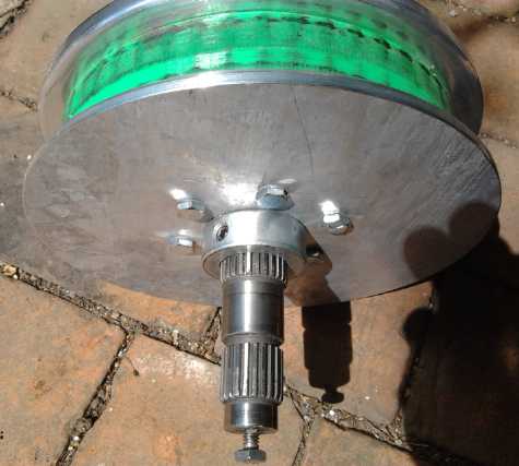
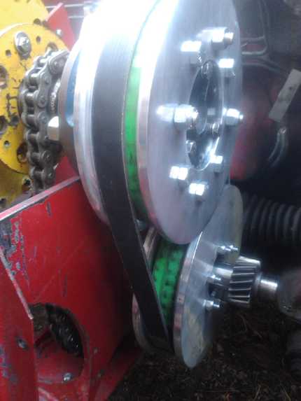
Differential Variable Transmission
with Slipping Belt that Returns Power to Motor Shaft
 On the 10th I finally got
a bit of project work done: part of one of the pulley sides. The
splined center piece that went on the shaft was a bit too wide, and
held the side away from the pulley. On the 12th I did some more, and I
figured out that if I machined a 'bowl' in the center of the inside
side as deep as the offending extra width, it would
fit. But it didn't fit in my small lathe to be able to dig it.
On the 10th I finally got
a bit of project work done: part of one of the pulley sides. The
splined center piece that went on the shaft was a bit too wide, and
held the side away from the pulley. On the 12th I did some more, and I
figured out that if I machined a 'bowl' in the center of the inside
side as deep as the offending extra width, it would
fit. But it didn't fit in my small lathe to be able to dig it.
I took
it down to AGO where a new machinist did it for me after the piece he
was presently working on. Marvelous! In the meantime, I had
done the other side for the same pulley. The edge rounding, to
keep the belt from rubbing on a sharp corner and wearing rapidly or
even
jumping off, didn't match. Oh well! I also had to trim the outer
diameters down a bit, as fitting it on the car showed that the sides of
the two pulleys were going to collide - I wouldn't be able to
get both pulleys on. I hadn't thought they were that close together;
apparently less than 7"!
 The first pulley was the bottom one, and only a 1/4" bolt
with small split washer that just might bend and slip through holds it
into the differential left side. There's no room inside the
differential for anything bigger and better. The second one was the
top, and the drive shaft, pulled out as far as I could, was a
little short, so it was only gripping at one end of the SDS bushing.
These things weren't satisfactory, but the bottom seemed almost
problematic, and changing the top shaft would be a fair bit of work.
The first pulley was the bottom one, and only a 1/4" bolt
with small split washer that just might bend and slip through holds it
into the differential left side. There's no room inside the
differential for anything bigger and better. The second one was the
top, and the drive shaft, pulled out as far as I could, was a
little short, so it was only gripping at one end of the SDS bushing.
These things weren't satisfactory, but the bottom seemed almost
problematic, and changing the top shaft would be a fair bit of work.
 By the 19th I had everything together and on
the car,
having done the idler wheel tensioning arm and its connection to the
shift lever that day and the previous. I found a piece of "U" shaped
channel steel for it that was the perfect shape. However, the thin
metal proved more flexible than I'd hoped, twisting to the side
some when pressure was put on the idler pulley.
By the 19th I had everything together and on
the car,
having done the idler wheel tensioning arm and its connection to the
shift lever that day and the previous. I found a piece of "U" shaped
channel steel for it that was the perfect shape. However, the thin
metal proved more flexible than I'd hoped, twisting to the side
some when pressure was put on the idler pulley.
With these three deficiencies my level of confidence that
it would actually work on the first test was about 2%. Sure enough, the
twisting arm didn't seem to put enough pressure on the idler pulley,
and after a few moments the upper pulley fell off the end of the shaft.
First order of business would be to make a shaft about 2" longer. Then
somehow stiffen the arm. Then would the bottom pulley hold okay?
I considered making a very long drive shaft that would
be the motor shaft and run all the way across the transmission
(~17"), but then I considered that then I couldn't take the motor off
without disassembling several things, and the transmission with the
motor would be too heavy to handle. The motor with the 13 pound
flywheel was now ~42 pounds all by itself. Better to put in a coupling.
I milled the required keyway slots in a 9" piece of shaft
on the 23rd. None of the 1" shaft parts would fit on the '1"' shaft -
it was slightly oversize, and a bit oval. It also wouldn't fit into the
1" center hollow in the lathe chuck. On the evening of the 24th I took
it out to the somewhat larger lathe at Victoria Makerspace and trimmed
it down - the first use I'd made of my rather pricey membership in well
over a year. It worked much better than mine for this job, the whole
head having a center hollow bigger than 1".
The next day I started trying to assemble and
fit
everything. I decided to get rid of the shortened trailer wheel hub. It
pushed the top
pulley out about 1/2" over from the others. And with the joy couplings,
what was needed now was a single bearing that could be twisted a bit to
line up with the motor shaft, wherever it was: a pressed needle
bearing.
I found it would be very simple to grind 3 semicircle crescents for
bolts in the extreme outside of the press fitting, and then it would
fit securely, held by the same bolts that had held the trailer hub on.
I was very reluctant to cut the sun gear off the motor
shaft, but nothing else worked (even with a propane torch), and I was
even more reluctant to disassemble the motor so I could press it off in
the hydraulic press, or replace the whole shaft. If I ever go back to
the planetary gear, I'll regret that.
The joy couplings had only one set screw - where the key
was. I remembered how the electric Caik outboard had been messed up by
one of those working its way up the shaft with the key until it had
forced the motor shaft and rotor up and it jammed against the stator
compartment wall. So I took the two couplers and drilled set screw
holes
at 90° to the originals for a proper lock onto the shaft. Then I
hunted around for 5/16" set screws but couldn't find any. I thought I
had at least one! I finally got some bolts for temporary use, only to
discover that I had now somewhere misplaced one of the couplers. After
everything else was mostly done, with it still not found, I quit for a
while. Later a fresh search found it still in the vise from threading
the new set screw slot. I'd looked on my messy workbench all around it.
I took it out to the car and somehow found that I had now misplaced the
rubber cushion piece that goes between the two metal ones. Another
search all over, a coffee and some other things... Finally I rolled the
car back a few feet in case it had somehow fallen under it. Sure
enough, there it was.
I had to carve a small 'V' out of one side of the
transmission box body because it was in the way of a bolt - just a bit,
and I had to carve a bit of a motor mount piece that wouldn't quite
adjust to where I now needed it. Then I couldn't move the new shaft out
quite far enough because the key for the chain sprocket went
just a bit too far that way.
The next day (26th) I took it apart, cut off a bit of the
key, and put it all together. With the new bearing arrangement, the
shaft was about 3" longer than it needed to be. I could have just used
the old one! The car wouldn't move, but it didn't seem the idler pulley
got very tight. I put a bungey cord on it that I could pull from the
driver's door. I operated with one foot outside, one on the electron
[gas] pedal, and one hand pulling the cord. Not an arrangement for
going very far!
The car would go backward from a level to "almost rolls by
itself" slope, but not uphill. It did go smoothly. It wouldn't go
forward. Evidently it needed a second idler wheel around the rear for
that, or extreme tension on the front one. The ABS plastic pulleys and
or the drive belt very soon smelled quite hot, much sooner than the
motor started getting hot. Somehow I hadn't considered that at any time
before or since making ABS pulleys on the 3D printer. I can see some
changes will be needed to the materials being used and of course to the
idler wheel mounting, as already noted. Maybe once those are done it'll
start moving more robustly? - I sure hope it's much more!
The next morning (27th) I tried again and this time the
belt jumped off the pulleys. It was really a poly-V belt, and it had
melted poly-V grooves into the pulleys, which reduced the effective
pulley diameter and loosened it. I turned it inside out, flat side out,
but somehow that was even looser. The chain needed another link to
get the pulleys a little farther
apart. But obviously those pulleys weren't going to last. After all
that work on them!
Either I could make some the same of another material, or
I could change the sizes entirely and have sizes that wouldn't spin the
differential so fast once it was in sync. And since the car movement
had been less than robust, I should probably size them for a greater
speed reduction to the wheel, per the tables in last month's TE News.
If I made one smaller pulley, the slip would be on it. Then I could
keep the lower pulley without it quickly melting. Of course, it would
need a shorter belt. I guess I'll have to make one from a polypropylene
strap, melting the ends together per an issue of TE News a while ago.
Perhaps better still, I could line up the ends flush, and bridge them
by melting a second piece onto the outside.
But making new pulleys and changing setups is time
consuming. Perhaps I should try the flat side of the belt (adding
another 1/2 chain link), and just replace the idler mounting for
now, and see how that works? After all I'd hardly run it and I might
find I want to change other things or do something differently once I
had this working as best it may as it is. (And if the belt was tight
enough when loose, maybe the idler mounting will work 'as is' too.) I
added the link, made the adjustments, and tried again with similar
results - the car would only go backward from an easy spot, and stalled
when the going got tougher.
Furthermore, the idler pulley needed a lot of
tension to engage the belt sufficiently, and it seemed the bolt
adjusting the height of the bearing, and hence the tension on the chain
and on the belt, had slipped down in its slot, in spite of being
tightened as much as I could. Thus, the belt loosened off as it went. I
think that probably happened before too, and was probably part of
the problem with getting the car to move and to keep moving. Something
will have to be added or changed to lock the adjustment securely in
place.
Later I realized the smooth surface of the belt was much
slipperier than the other side. And when I went to buy a second idler
pulley for "forward" I saw a torque converter belt used in small
motorcycles. If I had a belt that gripped the edges of the pulleys, it
would take a lot less pressure for it to have the required grab on the
pulleys. Finding one that would fit is another matter. Perhaps I can
make something out of ropes or multiple layers of polyproylene
webbing/strapping?
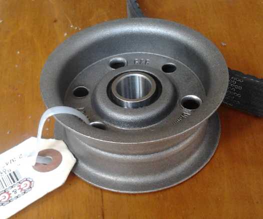 New Idler Pulley
Let's see... on the motorcycle, there's a cam wheel with
indents set at different places. When the chain is adjusted, rotate
that
wheel as far as it'll go and lock it there. The chain slot can't slip
without the wheel moving to a lower position. Something like that to
keep the adjustment from slipping...
Electricity
Generation
Solar Panels
for Charging the Miles Electric Truck?
I started driving the truck more in July. Where it had
been able to do 30 MPH with the original bad or intermittent motor
rotation sensor, after the repair it would only do 25. When it hits 26
the motor switches off or even to braking to keep the speed down.
That's disappointing, because I'd be embarrassed to accumulate
a line up of traffic when I drive. So I stick to short very local
trips. The puzzling thing is the Miles vehicle frame, used for a number
of similar vehicles, is supposed to be
fully road safety rated, so why are the electric ones, only, limited
in speed? All I can think of is that the motor would be over-revving,
beyond its specs, above 25 MPH. It certainly does wind up! If it wasn't
for the fact that it might have trouble starting up from a pothole or
whatever, I'd think it would generally be better if they'd stuck it in
3rd gear instead of 2nd. A "2-1/2" gear might have been ideal.
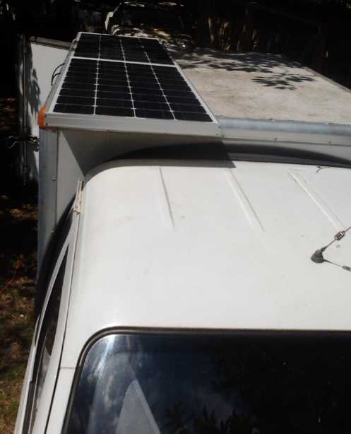
The
truck has a flat roof over the cargo box, and on the
23rd I decided to try an experiment. I had been
thinking of using two 90 watt solar panels in series as a possible
charging system for the 36 volt Sprint. The maximum open circuit
voltage per the specs is 22.1, so two would be 44.2. The truck is 72
volts. I set the two panels on the truck and measured about 40 volts.
For charging a 36 volt segment, that would be 13.33 volts per 12
volt section - a good float charge voltage for lead-acid. I connected
them to 1/2 of the batteries, nominally 36 volts. They initially (after
connecting them for a few seconds before I remembered to check)
measured 38.3 volts. They'd have been lower if they had needed
charging, below 38. When I checked before connection, the panels said
39 volts.
Clouds came on and off, and the charging current varied between 50mA
and 330mA. The panel will supply about 3 or 4 amps (4.9A at
MaxPowerPoint at 36.2 volts) if the load has a lower voltage - ie, if
the batteries are low. Well, they could keep
the charge up, and on sunny days could do much of the charging if one
was patient. (Maybe all of it for the amount I drive it!)
After 20 minutes the voltage was 38.6. But tree leaves
started shading one of the panels, and it was soon down to 38.1. It
seemed the batteries were feeding into the panels, so an isolating
diode would be needed. With the voltages already marginal, I begrudge
another 1/2 a volt loss. Maybe it should be active rectification with
mosfets?
The next morning there was a clear blue sky (no clouds, no
chemtrails - a bit of luck), and around 10:30 DST there were no shadows
on the truck. I took the panels back out and set them on top. They read
41.0 volts. I found an alternator diode and again connected the panels
in series to 1/2 the batteries, through it. I got 40.0 volts open
circuit. (As panels warm up, their voltage drops.) When connected, the
panels dropped to 39.2 and on the battery side of the diode, 38.4.
Inserting the current meter, it showed .40 amps.
Well, that seemed to work nicely - on a sunny day with no
shadows on the panels. There's lots of room for 4 of those panels on
the square roof if they overhang the cab a little. In fact the panels
are 22" x 46", and the space per panel is 27" wide, or 29" if that
silly vent wasn't in the way. Should I get 2 more of the 90
watt panels, or should I get the biggest ones that will fit with that
voltage spec, perhaps 140 watts? Two more 90 watt panels is
definitely the cheapest option (~400$) since I already have two, that
have been sitting around unused for a couple of years now. They would
provide a rated 360 watts. The 140 W panels, which would make 560 total
rated watts for about 1000 $, were a good width at 26.4", but they were
almost a foot longer and would need a "roofrack" over the cab to hold
the front ends steady. I decided, if I was doing this configuration, to
stick with the 90s.
Then I thought that perhaps a better option would be to
find 3
somewhat shorter "full size" panels of over 200 watts, and use three 24
volt charge controllers. Two panels could go sideways over the box. The
third one would need a "roofrack" frame to mount over the cab. These
could charge with over 600 rated watts, even 1/2 the speed of the
plug-in charger. At well over 1000$ this
would also be the costliest option. But since the charge controllers
would be pulse chargers that should improve battery life, it would
replace my present desire to replace the existing 72 volt charger with
six 12 volt pulse chargers each costing 140$ + taxes, a theoretical
saving of 940$
plus all the electricity eventually saved.
My search eventually disclosed that panels are made
with 36, 60 or 72 cells. I have two 54 cell panels on my roof from
2012,
but HES says these are no longer made. They're the voltage and the size
I want for the truck for the three banks of 24 volts, but I only have
two of the three needed, and I would also have to extract them
from my high, steep roof (and replace them with others).
With existing choices then, I can't fit the three panels I
need to get the 24 volt charging systems. I don't want panels that
stick out past the box (back or sides), because the first time you get
the truck too close to something, instead of a near miss (or perhaps a
dent) you'll hit with a solar panel and probably break
it.
I finally concluded that the best solution (and only since
they are
6 volt lead-acid batteries) would be the four 90 watt panels as four
18v
charging sections, and to design my own oscillator circuit to drive
some
switching
mosfets, to switch the connection (the minus side of each panel) on and
off at high
speed to give "pulse
charging", which will automatically weaken to "not much" as the
batteries reach full charge since that's the voltage the
panels are... if it's sunny... in the summer. And it would have a
shutoff for whenever the panel voltage is less than the battery
voltage. The mosfets would act as "active rectifiers" without the loss
of
over 1/2 a volt for passive diodes - a notable help with the marginally
high
enough voltage.
Then in theory if one battery gets weak earlier, I only
need to replace a set of 3 instead of all 12. Of course the other sets
will doubtless go soon enough, but it spreads out the expense and gets
more the maximum life out of each battery.
One caveat: I would have to park on the street to get the
sun. My yard is too shady. (Or cut down the old cherry tree, which is
actually long overdue anyway. But that would only be a partial solution
since the house itself shades the driveway much of the afternoon.)
---
To even just "float charge" nickel-metal hydride batteries
well, the open circuit voltage would have to be 42.0 volts (even
assuming low drop active rectification). The most I got in full sun was
41 volts, and even that soon dropped to 40.
I figured out why the open circuit voltage had gone down
the first day between readings: Just one of the several spec sheets I
looked at had a temperature graph. It showed lower voltages at higher
temperatures. The spec.ed voltage was 43.2v at 25°c. Theoretically
that meets my 42.0 volt requirement. But it dropped down to about 38v
at 50° and 34v at 75°. As my black panels sat out in the sun
they got warmer and their voltage dropped.
So getting near the highest rated voltage, to over 42.0v
for a NiMH float charge, sounded fine, but it was actually a
fantasy. The panels would have to be kept cool in full sunshine, and
they would have to be aimed at the sun. But really the only practical
orientation on a vehicle roof is flat. So my original plan for charging
the Sprint with solar wouldn't work. Like the Peltier modules, solar
panels could be made in just about any voltage rating in small steps,
but they're made either 22.3 volts or somewhere over 30 volts, 36, 60
or 72 cells, neither of which seems very convenient or efficient for
either 12 volt or 36 volt battery charging. (Maybe it helps them sell
DC to DC converting charge controllers?)
So the Sprint with NiMH and or lithium cells will need
another plan. Unless... if I used only 8 NiMH cells in the third "12
volt" battery, it would be 33.6 nominal volts instead of 36, and the
panels could put out 2.8 volts less for float charging: 39.2 volts
instead of 42.0. That could work, but it would bring its own set of
headaches, especially for charging the last one from three regular 12V
chargers.
Oscillating Water Column (OWC) Ocean Wave Power
Buoy Drawings
Here are some drawings I did to illustrate how an OWC
sytem
for capturing wave power might be implemented. The design can be scaled
to sizes from "demo" to very large.
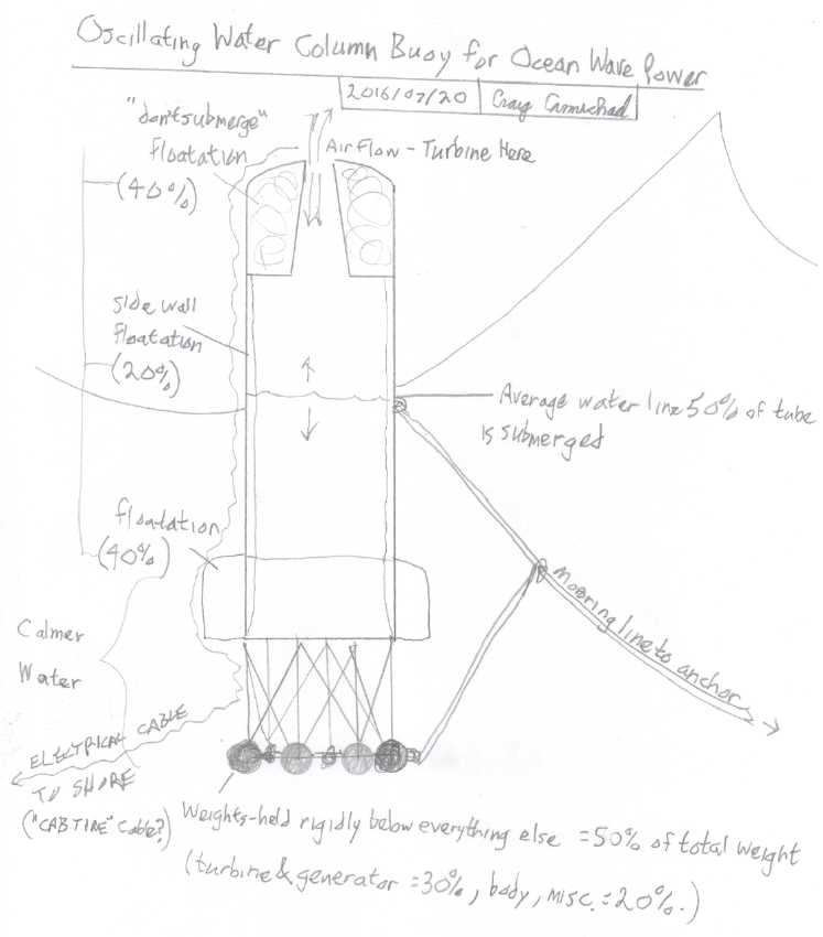 The open-bottom buoy
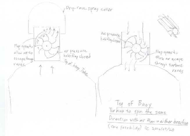
One idea for a turbine to turn the same direction with air inhaling or
exhaling
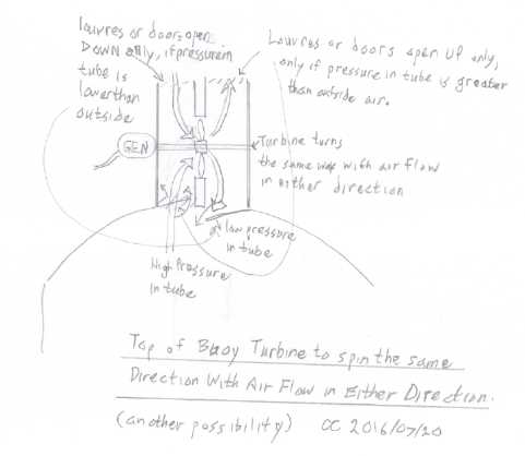
A propeller type wind turbine approach
http://www.TurquoiseEnergy.com
Victoria BC Canada