Turquoise
Energy Ltd. News #103
covering August 2016 (posted September 2nd 2016)
Victoria BC
by Craig Carmichael
www.TurquoiseEnergy.com
= www.ElectricCaik.com
= www.ElectricHubcap.com
= www.ElectricWeel.com
Feature: UNIVERSAL INFINITELY VARIABLE TRANSMISSION (UIVT):
Reverse-Idle-Low-Street-Highway
reduction ratios with One Smooth Lever. Efficient. Cars, Boats...
windplants? aircraft?
[see Month in Brief, Electric Transport]
Month In Brief
(Project Summaries)
- UIVT: from Sprint/Variable Transmission project - Ocean Wave Power -
New Chemistry
Batteries (Air-Nickel) - DIY Pelton Hydro Power with a 500W EBike Hub
Motor
In Passing
(Miscellaneous topics, editorial comments & opinionated rants)
- Material and Social Sustainability - Rain Bombs -
Local Societal Dysfunctionallity - Precious Metals Price Manipulation
- In Depth
Project Reports -
Electric
Transport - Electric Hubcap Motor Systems
* Electric Hubcap motor, Chevy Sprint & Differential gear Variable
Transmission:
- New refinement: Belt & Pulleys Variable Torque
Converter ("CVT") replaces slipping belt, making a...
- UNIVERSAL INFINITELY VARIABLE TRANSMISSION (UIVT)
* Double Barrel Torque Converter - Design Refinements... to be used in
the above!
Other "Green"
Electric Equipment Projects (no reports)
Electricity Generation
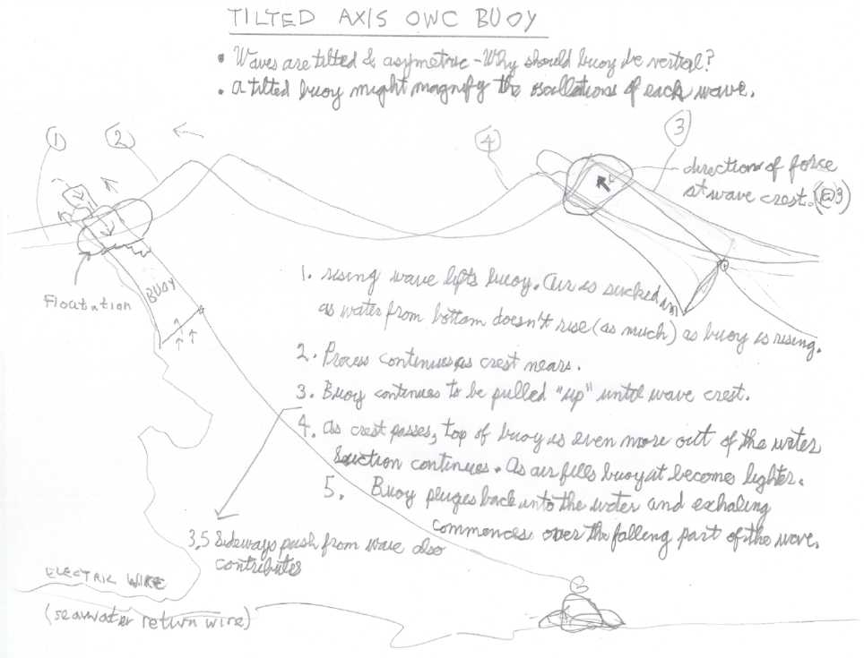
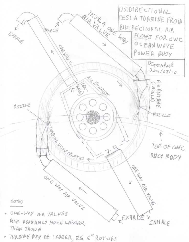
* Oscillating Water Column (OWC) Ocean Wave Power Buoy Drawings
* Waves are angled: Angled Buoy idea
* Green opposition to wave power?!? Really?!?
Electricity Storage - Turquoise Battery
Project (NiMn, NiNi, O2-Ni), etc. (no reports)
August in Brief
On April 16th the insurance ran out on the electric Mazda RX7, and
on August 21st I finally sold it for a low price after removing all the
pricey
batteries. The buyer said he pulled out the parts
for another conversion and had the rusty old carcass towed away. I note
that a
replacement motor alone costs
substantially more than I sold the whole car for. Ah well! (And the
'Curtis AC34' motor in the Miles truck costs 3500$US new!) So the
RX7-EV
is gone, the 4-Runner is gone, and the Tercel is retired. The Miles
electric truck is a better vehicle than the RX7 was. I haven't gone a
long distance in it yet, but the batteries stay up - it obviously has
far more range. (And that's with only 72 volts, 180 amp-hours - 12960
WH. And replacement batteries would have about 230 AH, giving 16560 WH.
I don't know where they found these lower capacity ones.) The Echo
fills my longer distance, higher speed travel needs, and the
Sprint has sat in the back yard
looking ever more promising but still not quite there... until I had a
sudden "Eureka" moment (not without antecedents) of a fantastic new
transmission conception. For water transport, the boat simply
awaits reassembly of the electric outboard, whenever I may get around
to that.
THE UNIVERSAL INFINITELY VARIABLE TRANSMISSION! (UIVT) - Chevy
Sprint/Variable Transmission project
I tried to get a wider and maybe 'stickier' belt for the
slipping belt system, but I was having trouble finding anything
suitable. Making
one from PP webbing/strapping didn't work out. I looked at belts made
for variable pulley "CVT" torque converter systems for mopeds and
snowmobiles, and from there came up with a whole fresh and fantastic
idea. As per last month's
tables, if the pulley ratio was 1.5 to 1 ratio (1.5:1) with the chain
drive being 3:1, the elements of the differential gear would spin 2:1:0
such
that the car, driven by only the right wheel, wouldn't move. I was
using 1:1 ratio pulleys on the left side. That should be good
for higher speeds, but I was having trouble getting the car to move. If
the ratio was say 1.4:1, the car should be very easy to move, with a
high
motor speed moving the car quite slowly. Then, 1.6:1 would cause the
car to
move slowly in the other direction - without changing the motor
direction! Now, instead of picking one specific ratio and slipping the
belt until the speed conforms, why not use the variable width pulley
"CVT"
system, and simply control the variable pulley ratio, and hence control
the reduction ratio of the chain drive system, with the shift lever?
Then all those useful ratios mentioned above and in the tables last
month would
all be available on demand while driving. Instead of a simple 'gear'
ratio, the final ratio depends on the difference between 2
ratios - 1 variable, 1 fixed - applied to 2 different elements of a
differential or planetary gear, which together differentially drive the
3rd element of the same gear. Hence it might technically be denoted as
a "differential
transmission".
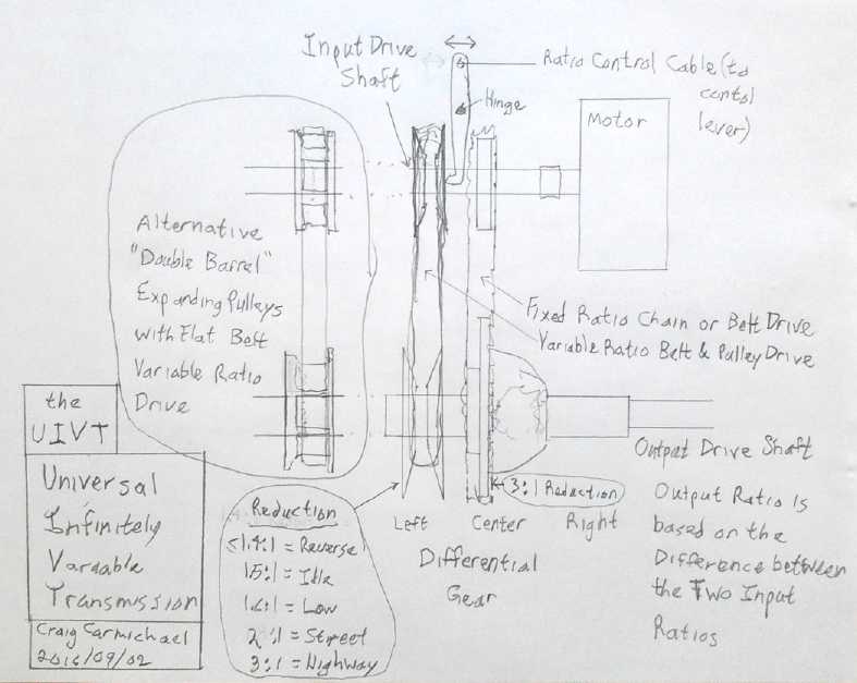 First sketch of the Universal Infinitely
Variable Differential Transmission, configured as first conceived
First sketch of the Universal Infinitely
Variable Differential Transmission, configured as first conceived
All those ratios are within the compass of the "CVT"
variable
pulley system. With the pulleys and belt I found, it should be variable
from less than 1.5:1 up to maybe 3:1 (a difference of a little more
than
2 to 1) if it was ideally set up.
 Variable Pulley Transmission (1" shafts -"up to
10 HP") from PrincessAuto.ca
Variable Pulley Transmission (1" shafts -"up to
10 HP") from PrincessAuto.ca
This would be just 1/2 of the UIVT, the other being a fixed ratio (eg)
chain drive.
In principle we here have an infinitely variable
transmission that is completely predictable and understandable by
anyone who 'gets' the operation of a
differential or planetary gear. There's no more slipping belt 'clutch'.
It can go from one direction through idle to the opposite direction,
with ratios from "bull low" to "highway speeds", seamlessly with a
single sliding lever action. And of course the lever's action could be
automated if desired. In addition to automotive uses, it would
have practical applications in boats (where it would eliminate the need
to match propeller and motor or engine RPM.s in advance by allowing
adjustment under way), and it could be used to turn a windplant
generator at a constant speed in spite of varying wind and propeller
speeds. It might possibly have aircraft uses for governing propeller
speed as well.
At the risk of there being something I haven't seen
yet, or of having someone else come up with something better tomorrow
(never say "Impossible!"),
it looks like I've come up with an ideal form of transmission,
better than anything else that's ever been
created. I've looked a lot for variable - and now for "differential" -
torque converters and transmissions over the last few years and found
nothing comparable, except one that was so complex with so many gears
that I couldn't wrap my head around it -- much less make one.
Up to last month I only had things that just might or
might
not do the job. This month has brought a clear concept for a seemingly
ideal
form for a transmission. It illustrates how individual technology
advances aren't a linear progression but occur in sudden leaps of new
imaginings. But nothing would have been accomplished except for 7 years
and 3 months of trying a wide variety of ideas trying to create some
sort of workable variable torque converter or transmission to run an EV
with
a single smaller motor.
 I ran an experiment with fixed V-belt pulleys, and found that while a
high reduction ratio was obtained, it was impossible to keep the belt
from slipping to go uphill. A chain can take the high torque, but a
V-belt can't. And I had trouble getting enough tension with the flat
belt, too.
I ran an experiment with fixed V-belt pulleys, and found that while a
high reduction ratio was obtained, it was impossible to keep the belt
from slipping to go uphill. A chain can take the high torque, but a
V-belt can't. And I had trouble getting enough tension with the flat
belt, too.
For actual production, I
don't think much of the likely efficiency of the variable width pulleys
system. As used here it's ideally just changing the ratio of the chain
drive to the center of the differential. But as configured driving one
end of the differential directly, it would have to take a lot of
torque. As with the other belts, I'm not sure it could be made strong
and tense enough to not slip.
A high efficiency alternative would probably
be the almost as recently conceived "Double Barrel Torque Converter"
type of "CVT" with a flat or
poly-V belt. But this would probably also slip. So instead of driving a
car differential directly, the main gear could be a planetary gear,
with the variable section turning the sun gear. The
speed of this variable drive section would then be much increased and
the torque as much decreased, with the ratio determined by the relative
size of the sun gear used.
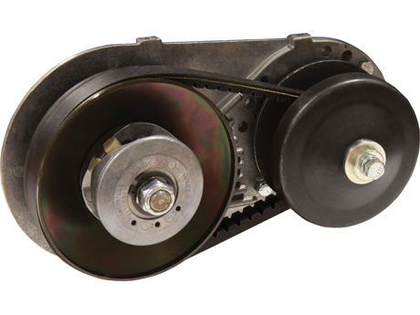
 These centrifugal clutches illustrate the basic
idea of the "expanding barrel" pulleys.
These centrifugal clutches illustrate the basic
idea of the "expanding barrel" pulleys.
I played with some drawings for means to construct them and
connect them to be expandable under control of a lever
These
features will be pursued, along with ideas in earlier issues for a dry
running transmission with plastic gears that need no lubrication to
mesh with steel ones, all produced in a larger size to spread loads out
for the softer materials. I've ordered the essential equipment to cut
spur gear teeth, after looking up techniques for gear making on
youtube. At least the plastic ones should be easy!
Ocean Wave Power
Anyone who thinks it's just wave power that has trouble
handling
storms should watch one or more "Wind Turbine Fails" videos of big
windplants catching fire and burning, blades spinning off, and towers
breaking and falling over.
Of course, I've seen pictures of logs being tossed up on
end by big waves at the shoreline on the west coast of Vancouver
Island, and even heard of them landing on a coastal highway - and heck,
I've seen it with smaller logs right here in town. So never mind waves
- buoys should be designed for surviving being hit over the head with
large clubs. But hopefully if they're away from the shore they'll only
be bumped from the side, not hammered from above.
So I figure there are a few construction rules to observe:
1. It has to float even if punctured, broken loose from its moorings,
tipped over,
and generally knocked about. This says it probably needs closed-cell
foam filled floatation chambers.
2. For the BC coast, it has to survive very occsaionally being hit by a
log anywhere near the waterline. It has to either be strong enough to
withstand the hit, or flexible enough to bounce back after being hit.
Foam filled plastic laminate skins probably aren't going to cut it.
3. Of course it has to survive salt water corrosion, preferably with no
maintenance for years. 2 and 3 are starting to suggest a moderately
thick aluminum outer shell, stainless steel being heavy and costly.
I ordered a Tesla turbine (high efficiency air turbine)
and Tesla one-way air valves (no moving parts!) to try out. I changed
my conception of the best form of a buoy to match those of most
peoples' designs on youtube. But I saw the buoy being pushed sideways
at wave crests and figured that they might be designed to tilt over on
rising waves to take best advantage of wave force vectors near the
crests, which do have a strong horizontal component. (Hmm... it might
not work very well.)
Then the out-of-the-way place where I had expected we
could quietly moor the buoys off the shore of the property long enough
for a testing and development phase was sold. The idea was pretty far
"outside the box" for its likely advantages to be swiftly grasped, and
potential funders either didn't think it was viable or were too slow
deciding. Or it just sounded like more money than they had been
considering for the project. It had to be "struck while the iron was
hot", and it wasn't.
But with my previous experiences and hearing of various
tales, I decided that without a suitable property on wavy waterfront,
pursuing it would be pretty much an academic exercise. The funders
heard the same story. Permission to moor them for longer term testing
and then to connect them to the grid would probably never be granted by
government. (I can already visualize the buck being passed from hand to
hand through the bureaucracy with no one feeling they had both the
authority and the technical understanding of the project to lease or
assign a piece of waterfront land (one department - provincial), lease
the foreshore and tidal zone at the same place (another department -
federal) and give a go ahead (another department?) - until we gave up.)
I'm pretty sure that's why it isn't being done anywhere already, except
a few off-grid experiments and at the small Gibraltar installation
where (doubtless) only local approval for the project would have been
needed.
New Chemistry Batteries - Air-Nickel
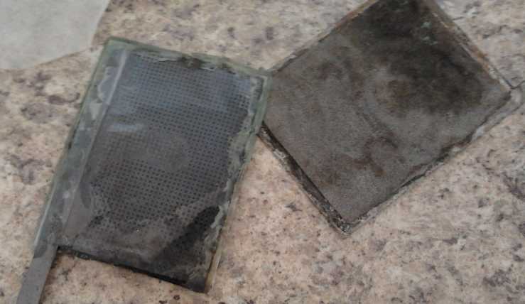 I really didn't do much on this,
but on the 22nd I finally got around to dropping some
potassium sulfate onto the nickel-air cell. It read about .21 volts.
The beeswax was gone from around the entire edge (so much for using
that as a seal!), and it was in three pieces: the cupro-nickel bottom
plate, the nickel foam and powder as a single loose piece sitting on
that, and the separator sheet, carbon fiber and top piece of presumably
permeable
plastic all stuck together on that, with the "graphite foil" electrode
terminal.
I really didn't do much on this,
but on the 22nd I finally got around to dropping some
potassium sulfate onto the nickel-air cell. It read about .21 volts.
The beeswax was gone from around the entire edge (so much for using
that as a seal!), and it was in three pieces: the cupro-nickel bottom
plate, the nickel foam and powder as a single loose piece sitting on
that, and the separator sheet, carbon fiber and top piece of presumably
permeable
plastic all stuck together on that, with the "graphite foil" electrode
terminal.
I hooked
up the power adapter, which provided 3.0v through 560 ohms for 5 mA of
charging current. It rapidly (seconds) ascended to .66v, then began a
slow (minutes) rise through .8v, still under 1v after 1/2 an hour.
After a few hours it was around 1.8v, and it stayed there. The
trick here is that with the edges open, it'll keep drying out, and I'll
have to keep adding water, and the readings taken will be less than
definitive because of not knowing how moist it is.
When the charge was removed, voltage quickly sank to
around 1.2v, then 1.1. However, it kept self-discharging from there. I
lost track of it (twice) and later found it down to about .5v.
 By the morning
of the 24th it was 2.05v (on charge), which
meant that the water was drying up. I pulled the top off and added a
few cc.s. There seemed to be some sludge on the nickel sheet, and I
brushed it with a stiff brush. Some areas were clean metal, as they
should be if it was charged, others were dark and dull. There didn't
seem to be any reason for the patterns, such as depressions in the
surface.
By the morning
of the 24th it was 2.05v (on charge), which
meant that the water was drying up. I pulled the top off and added a
few cc.s. There seemed to be some sludge on the nickel sheet, and I
brushed it with a stiff brush. Some areas were clean metal, as they
should be if it was charged, others were dark and dull. There didn't
seem to be any reason for the patterns, such as depressions in the
surface.
When I put it back together, I tried pressing down on it
with different pressures. Obviously, with no pressure, the bulging top
piece wouldn't make much contact with the middle. Reading the voltage,
it seemed that more pressure was helpful up to a few pounds, but more
than that only improved it very incrementally. And would it not finally
puncture the separator sheet somewhere and short the cell with too much
pressure? I set a
small lead-acid battery on top of a kiln block on top of a sheet of
porous fabric on the cell to give it sufficient weight but still let it
breathe. The voltage only went up to about 1.5 volts instead of 1.8.
Apparently the internal connections were somewhat better. But really,
why wasn't it taking hundreds of milliamps instead of ones? A paper on
one experimental zinc-air cell showed that it did 200mA/sq.cm without
too much voltage drop. At that rate my cell should be capable of 15
amps. What might be stopping it from performing like that? I turned up
the current a bit (2.3v/280 ohms=8mA) and the voltage stayed under
1.6v... still slightly better than it was. Maybe I needed to try
physical
experiments with materials, placements and pressures to try and improve
things?
Also, thinking back to the
nickel-zinc in oxalic acid cell I once did,
I might try that acid as another alternative electrolyte. The
improvements needed are about 3 orders of magnitude, but perhaps
this can be achieved -- if I can find time to really start trying
things out.
"DIY Pelton Hydro Power - with a 500W EBike Hub Motor" ... and 3KW
on the
Zambezi river
After the last hydro power video last month, here's
another one I ran across with the above title. This person simply takes
an old e-bike wheel with a 500 watt hub motor, removes the tire and
tube, and attaches a bent spoon at each spoke nut, making it a pelton
wheel. There are no added gears, pulleys, belts or chains, and it sits
on a simple stand over the water course. It could hardly be simpler!
The voltage he showed, about 14 VAC, should be good for charging 12 V
batteries if all three phases were full-wave rectified with 6 diodes.
Again we don't know how many watts the system might produce and one
suspects under 100 from the garden hose, but it might be somewhat more.
The limiting factor would probably be the motor producing limited
current at the speed attained.
What he didn't have (in common with many videos about
hydro power) is a source of pressurized water other than his garden
hose. The pelton wheel type needs good pressure. For lower pressure
water, one might create an overshot wheel with the e-bike wheel and hub
motor. The spoons would be replaced with some sort of cups that hold
the water, and the weight of the water in the cups turns the wheel. The
cups dump out as they reach the bottom and go back up empty. One might
place them beside the rim (even on both sides) instead of on the
outside of it to reduce the diameter and get higher speed. But that
would be a subject for experimentation.
I doubt sufficient RPM could be attained by giving it
paddles and mounting it over shallow flowing water as an undershot
wheel. There we would definitely be back to a more complex setup with
speed-up pulleys and belts or sprockets and chains.
Well, that led to lots of other videos on the same
subject. One thing of note seen from the next couple of videos: he'd
get much better results - more RPM and potential power, using less
water - with a pressure nozzle on the end of his hose. (These are
available wherever garden hose attachments are found.)
Another good watch was a video where a pair of connected
pontoons was
moored on the Zambezi river with a big paddle wheel between and a
spiral pipe mechanism to make a water pump,
pumping up to a set of cisterns up on the bank. The reason for that was
that
crocodiles lay in wait for people who took water straight from the
river, and sometimes they got someone. After that was running, they
added a
generator as well and said it was making 3KW. It looked rather
makeshift, but it seems quite similar in
essential form and output capacity to Rick Linden's 12KW pontoon hydro
generator project. ('fraid I don't remember the video's name - look for
'Zambezi River'. I recall there were some
North American university students involved.)
With a screen around the underwater space swept by the
paddle wheel, or maybe even without one, such units would be perfectly
safe for fish and crocodiles, virtually entirely environmentally
benign. I can't help but feel the straight sided paddles could be much
improved on. A curved "L" shaped paddle should cut into the water
smoothly at entry and even reflect it back (extra force), do just as
well in the middle of the stroke, and exit with the water still pushing
it and little friction.
These are just samplings of the various small
hydro-electric projects that can be seen on youtube. The only thing
most of us lack for free power is the flowing water.
In Passing
(Miscellaneous topics, editorial comments & opinionated rants)
Material and Social Sustainability
The piece below (not by me) explains the quite new concept
of Social Sustainability, which is centered on the core values of
Quality of Life, Growth (provision of opportunities & potentials
therefor) and Equality. When decision making is centered on enhancing
these values, with Empathy, Compassion and Love, and things which don't
enhance them are treated as secondary or rejected (or thrown aside
forcibly if necessary in cases of social predation), societies will
become stable and sustainable. We can see in the progression of our
societies and cultures that we don't have it yet! It will have to begin
at the local community (or even family) level and progress from there.
All people of all races, cultures,
ethnicity and nationality should have the same opportunities to grow
into the potential they brought with them into
life.
Today, “material” sustainability is a commonly understood
term. It encompasses things we can see and touch, like trees,
water, fish and air, etc. Concepts like “use only what you need,”
and “reduce, reuse and recycle” are familiar to many.
“Social” sustainability on the other hand, is much harder
to wrap one’s head around. It refers to concepts that include
quality of life, growth and equality, etc.
Many people are now realizing that we cannot truly succeed
until we apply both, material and social sustainability. Our
societies cannot survive over the centuries without both being equally
important. People are the only resource for creativity,
curiosity, inventiveness, intelligent choices – and these skills must
be taught to our children just as much as planting trees and cleaning
our waterways.
Conscious applications of these truths will yield far more
positive results than working with them separately.
Rain Bombs
In attempting to describe the enormity of the sudden "1000
year flood" deluges that we have been seeing around the world in the
last
couple of years, the term "lake from the sky" and "river from the sky"
have been used. (The "rivers" last longer and cause more serious and
extensive flooding.) Now a few have been caught on camera from a
distance.
They look like a nuclear bomb "mushroom cloud" there's so much rain
coming out of the cloud so fast. Hence the term "rain
bomb", formerly a "wet microburst" weather phenomenon, has been coined
or
brought into use to describe these extreme rain events, some of which
which in size might be termed "wet macrobursts".
Readers will know that I attribute the many bizarre
weather events of the last few years to geoengineering far more than to
climate change
brought about by fossil fuel burning, with atmospheric aerosol spraying
at the top of the list. The climate change we were getting was very
gradual. The rapidly accelerating climate chaos today is surely being
caused
by deliberate but obviously misguided attempts to halt global warming,
especially by the spraying. There seem to be a number of effects being
overlooked.
It seems that people noted the temporary cooling, even
global cooling, brought
about
by volcanoes that spew volcanic dust high into the atmosphere, and
simply seek to emulate that by spraying aluminum oxide and other
chemicals (mostly coal burning ash as I understand it).
But dark volcanic dust absorbs sunlight rather than
reflecting it, which heats the usually cold stratosphere. This is heat
that would normally have been made at the ground. So the ground cools.
And the heat in the stratosphere creates an inversion layer, disrupting
the normal vertical circulation through the atmosphere. This is
different than the effects of high albedo aerosol particles that
probably
reflect infra-red from the ground at night back to the ground, reducing
normal nightime cooling the same as cloudy nights. This has contributed
to the atmosphere containing much higher levels of moisture - "lakes in
the sky". Furthermore, reducing solar insolation as my solar collectors
indicate it clearly does, must slow the growth of plants, which absorb
carbon dioxide, so the levels of the greenhouse gas carbon dioxide will
rise. And the actual water vapor exhausted from jet engines is itself a
greenhouse gas that will cause temperature rise. So just the large
increase in the number jets flying at any given moment itself
exacerbates the problem.
The biggest weather results, so clearly seen, would be the
droughts and
the "rain bombs".
What you see here is called a wet microburst, a weather phenomenon that
occurs when cool air and rain fall to the ground, often during a
thunderstorm, at high speeds. Once this wave, so to speak, hits the
ground, it disperses horizontally, creating incredibly high winds
(sometimes over 150 miles per hour) and literal balls of rain. This
timelapse video shows the phenomenon in action, as you see what look
like giant waves moving toward the ground, expanding slightly before
making contact.
http://www.wimp.com/watch-a-literal-rain-bomb-descend-upon-tucson-arizona/
Bryan Snider recently caught this particular series of wet microbursts
in action above Tucson, Arizona. The footage Snider took just goes to
show the raw power of nature, and how quickly the weather can change.
This is definitely a sight to see.
Local Dysfunctional Society
It was mid morning, so I thought for once it would be a
good time -
I could simply drive to the store without encountering traffic jams,
buy a V-belt pulley, and drive home before having breakfast. Instead I
almost gave
up trying to get there at all. They were doing "roadwork" (which today
may even be just gardening in the center meridian) on one of
the only two routes between one half of Victoria and the other half. I
waited in the non-moving line for a while with no indication of where
the work was being done, how long it might be, or that it would ever
move again. I remembered that the last time they were working on a
light pole at the far end, this entire route was jammed for miles right
from one end to the other - people must have waited hours. I was very
glad I had been going the other way and was only an observer, not a
participant. But more often than not, I have encountered considerable
delays trying to get to the western part of town.
This time, a few cars trickled through from the other
direction, so it appeared the jams must be very long and in both
directions. I finally did a U-turn and went back (luckily there being a
rare spot with no planted concrete meridian just where I was stuck),
intending to take the
much longer alternative "highway" route. But I didn't get very far down
the road toward the highway either, before I could see it was also
jammed ahead, doubtless for the whole couple of miles, with other
vehicles trying to get to the highway to get around the blockade.
I turned down a side street, at this point intending to make my way
home again. Then I decided to try another and by now even longer route
to the highway, being part way there anyway. This one wasn't bad. When
I got on the highway, there was one delay, then the wall-to-wall
traffic started moving well. I made one wrong turn on the unfamiliar
route and had to turn around. (The route markings in BC are
lamentable.)
Knowing the other route was blocked, I took the same detour home.
Homeward was the only "normal", somewhat relaxed drive of the trip. My
45 minute, 20 Km trip turned into double that time and distance in
spite of circumventing the main obstacles. (and I hoped the milk for my
cereal hadn't been out of the freezer in warm water long enough to give
me a migraine, which would typically show up in the afternoon and last
until the following afternoon or evening.) The dysfunctionality of our
society even at the local level becomes apparent when it has been
obvious for 30 years that that road has needed to be expanded to 4
lanes, and
that there is an existing railway through this bottleneck with an
existing passenger locomotive that hasn't run in a decade, in the face
of crying commuter needs.
Whoever is in charge of transportation
facilities, having let things get to this pass and still doing nothing
about them, should be booted out on his ass, and someone who gives a
darn, whether or not they have any technical qualifications for the
position, put in his place. But apparently his supervisor, elected or
unelected, cares just as little. The worst problems could be easily
fixed with less expenditure than has already been spent in recent
years "beautifying" the horribly clogged streets, making dangerous
concrete obstructions in the roadways and even in intersections,
holding often large plants, many of which seriously impede visibility.
All our money seems to be being spent to make things worse for us.
Precious Metals Price Manipulation
Since the rapid climb to a high in early 2011, the
financial powers that be have colluded to lower the prices of precious
metals, cutting them in half and more by 2015; gold almost in half.
Some people tried to get a lawsuit happening about silver prices,
giving quite specific evidence, but the government took years and then
said "We don't see anything actionable." Since then, Deutschebank has
admitted to suppressing the price of gold in conjunction with a number
of other major banks. They have in fact spent countless billions of
dollars buying and selling "naked short" futures contracts with each
other on the COMEX to do so - for example, dumping 6.2 billion dollars
of "paper gold" into the market just in the past week - 1/4 of the
world's annual mine production of actual gold. (Probably they recoup
most of this by moving the price up and down. I don't know exactly how
it works.)
At the end of 2015 there was a turnaround, and prices went
up by 20 to 30 percent in the first months of 2016. What happened?
There was an announcement that perhaps few took note of, by two or
three of the biggest silver mines in the world, that they were going to
cease production in 2016, because they were losing money digging it out
of the ground. If there's one thing that would drive up prices fast, it
would be scarce supply. The "money changers" had to let the prices rise
somewhat to prevent that.
Some people thought the rising prices meant that with the
ever increasing demand, the manipulators had lost control, and they
were probably surprised when they stabilized, went down a bit again,
and stayed there. At some point the COMEX will lose credibility because
they can't deliver the promised physical gold or silver, and precious
metal prices will skyrocket. In Europe on September 1st there was what
looks like a failure to deliver gold by Xetra gold ETF, via
Deutschebank, but the situation isn't yet clear. ("That service is no
longer available." ...speaking of their own application procedure to
request physical gold delivery.) Whenever it happens, it will be pretty
sudden. Not only will prices skyrocket, there won't be any gold, silver
or platinum to be had anywhere except what people have already bought.
That day is not here yet, but it's coming soon.
---
Why is the first practice called a "rehearsal"? Isn't it
just a "hearsal"?
Ance a port has been used twice, is it a "report"?
Newsletters Index/Highlights: http://www.TurquoiseEnergy.com/news/index.html
Construction Manuals and information:
- Electric Hubcap Family Motors - Turquoise Motor Controllers
- Preliminary Ni-Mn, Ni-Ni Battery Making book
Products Catalog
(Will accept BITCOIN digital currency)
...all at: http://www.TurquoiseEnergy.com/
(orders: e-mail craig@saers.com)
Electric Hubcap Motor Systems - Electric Transport
Electric
Hubcap motor, Chevy Sprint & Variable Transmission...
and then!: the Universal Infinitely Variable Transmission (UIVT)
Differential Variable Transmission
with Slipping Belt that Returns Power to Motor Shaft...
Or maybe Incorporating a Variable Pulley Variable Transmission as one
component?
Early in the month I looked for a "variable
transmission belt" of the type made for small motorbikes and
snowmobiles. At Victoria Motorcycle Jim looked up a catalog for me and
we found a selection, including one that seemed to be the right length.
But my pulleys were 1.25" and I wasn't
really happy with a narrow 7/8" belt, the widest one. The whole idea
was to get some friction at the edges. So instead I tried to make one
of 1.5"
polypropylene webbing/strapping, wrapping it around twice and using a
clothes iron to melt the layers into each other. That was too wide, and
I made it a bit too long, so I wasn't happy with that either. And it
didn't seem that secure. I thought it would fall apart quite soon.
In the meantime I thought about the actual torque
converter it was meant to go on. I was using a 1:1 pulley ratio. With
"torque converter" variable pulleys, one could put a 1:1.5 ratio on the
differential left end. Then with the 1:3 chain ratio in the
differential center, they would both spin with the right end staying
stationary, ie, without trying to move the car. As that ratio was
changed from 1:1.5 to any lower or higher number, the right wheel would
try to move - backwards to the motor for lower, forward with higher.
The direction itself is unimportant, but the fact that it makes both
directions available is huge! If it was, eg, 1:1.45, full speed of the
motor would give a very
slow "bull low" movement of the wheel, while 1:1 or higher would offer
considerable vehicle speed. It would be a really smooth
transmission.
First sketch of the Universal Infinitely
Variable Transmission, configured as first conceived
My recent idea of a "Double Barrel Variable
Torque Converter" with variable diameter pulleys and flat belts (TE
News #101) could fill the same function as the variable width angled
pulleys more
efficiently, and over the month I came up with some good design ideas
for making one. Making and fitting either type will be a demanding job
- a
whole new and more complex section of the transmission to replace the
slipping belt section.
But I decided I was really onto something good here! If it
was robust enough, it could hardly fail to get the car moving, since
super high reduction ratios could be obtained at the shift of a
lever, or perhaps automatically. Here I've come a full circle, from
thinking the "CVT" variable pulley type of converter was probably a
pretty inefficient and flimsy drive system, to thinking it would be a
good way to control the
drive ratio, without it being the main force transmitting mechanism.
It would be ideal if it mostly only changed
the ratio, with the chain transmitting most of the drive. The way to
accomplish that is with a planetary gear instead of a differential
gear. The variable part would turn fastest with the lowest torque,
driving the sun gear. The smaller the sun gear is, the faster it must
turn to keep up with the others, but with proportionately lower torque.
Variable Pulleys
On Saturday the 13th I went to Victoria Motorcycle. Jim
wasn't there. the guy who was said take whatever if I knew where it
was, and call Jim to settle it on Monday. That might have
worked well except that I accidentally got two rear (wheel) pulleys
instead of one of each. There seemed to be extra parts, which I soon
realized were a centrifugal clutch shoes and drum. Since the
configuration would allow the car to go right down to zero speed with
the motor turning any speed, there would be no use for that. Just the
pulley.
It's probably rather lightweight. A more serious
problem is that it's sized for smaller shafts than the 1" diameter I
try to stick with.
I measured the approximate diameter of the belt on the
pulley in its inner position. It was about 4.5". Then I pushed the
halves of the pulley apart and pushed the belt in as far as it would
go, and got 2-3/4".
The next day I took one of them apart. Notwithstanding
that I managed to get a slip ring out from inside, a hammer wouldn't
budge the main bearing. I had to break up the smaller bearing inside,
then I was able to press the main one out in the hydraulic press by
putting a large socket under the center so it would have room to slip
out, and two 1/2" sockets (largest that would fit) into the inside so
the press could press through them on the bearing. This was nothing
like as bad as the alternator mentioned under "wave power" - a ton or
two of force and it slid out. But it was another case of something easy
to press together but much harder to get apart again.
On the 15th I showed the Sprint with the concept to
someone. He pointed out that
the differential gears would be stressed by spinning rapidly instead of
just turning a bit when turning the car left or right since they
weren't made for it, especially with
no oil bath. And that a "moped" "CVT" belt & pulley system would be
pretty lightweight for a car. I could hardly disagree. I said that what
I was making was really a prototype to
demonstrate the possibilities, rather than a finished product. And that
I might have to make my own larger pulleys.
Of course I could use small and large variable pulleys and
use ratios above 1:1.5. Then as the car went faster and the pulley
ratio approached 1:3 as the vehicle picked up speed, the gears in the
differential would slow and stop spinning. My fear in that is that a
small pulley might never get enough grip on the belt with the
considerable torque that's required, and would slip. So I would rather
use two large ones because it would be disappointing to make yet
another time consuming component that doesn't work well. OTOH, perhaps
I could use a "moped" large pulley as the small one and only have to
make the
large one? An interesting feature of the configuration would be that
the lowest drive ratio would be with the input pulley at its maximum
diameter, and the highest at its minimum, instead of the other way
around.
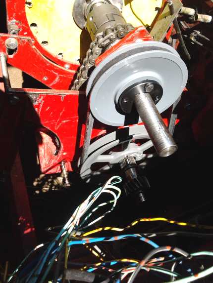
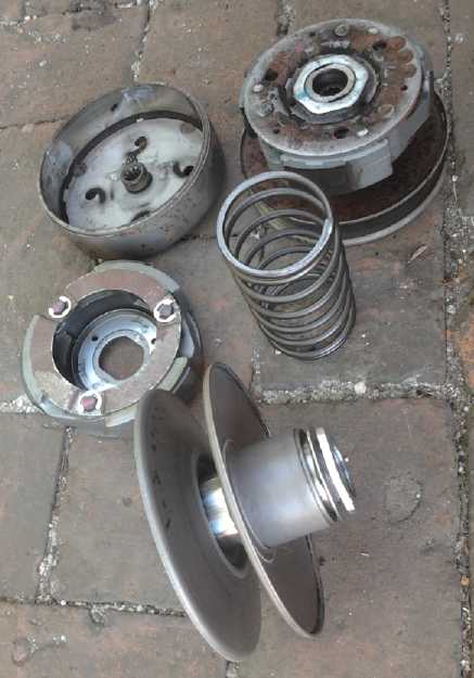 "CVT" variable output/wheel pulleys. One (back)
is together with
"CVT" variable output/wheel pulleys. One (back)
is together with
its centrifugal clutch. The other is separated into its components
with the variable pulley itself at the front.
Fixed V-Belt Test
On the 23rd I decided to buy another V-belt pulley and put
together a fixed ratio drive on the Sprint and see how it worked.
It was mid morning, so I thought it would be a good time
to drive to the store without encountering traffic jams, buy the
pulley, and drive home before having breakfast. But my 45 minute, 20 Km
trip turned into
double that time and distance. There is no need for daily all day
traffic tie-ups here - it's been created by uncaring politicians and
bureaucrats lacking in the core values of empathy, compassion and love
and resulting in degradation of these aspects of the other core values
of quality of life, equality and growth. (More on this aspect of
dysfunctionality of our society in "In Passing".)
The pulley I
had was about 5.25" and I got a new one of
7.25", giving a ratio of 1.38:1. What that works out to as the overall
ratio to the wheel I didn't check, but it's pretty close to 1.5:1 which
would be "idle", so it should be a pretty "low gear". I measured
everything in the store and found a 34" V-belt looked about right.
Things seemed to fit well, but it didn't work well. Tight as I managed
to pull the belt, it seemed to slip. At one point a pulley slipped on
the shaft. The car would move, seemingly easily enough, through easy
spots where the belt didn't slip. The gearing seemed good and
validated the "differential ratios" principle of the unit. It just
didn't seem to be hefty enough for the job. Bigger pulleys on both
sides would give the belt more friction, but there wasn't room to go
much larger. And the variable pulleys were substantially smaller, not
larger. I wasn't getting a good feeling about using them when even this
experiment
didn't work well.
Then it seemed the whole shaft wasn't turning freely and
seemed prone to jamming. I found set screws that must have come loose,
throwing off adjustments, and the chain wasn't running straight. Maybe
it was because I was prying with a crowbar trying to get more tension
on the belt.
For a car that's so easy to push around, it sure seems
hard to get it to move under motor power. Perhaps the most frustrating
aspect is that I've always wanted fatter belts and beefier hardware,
but nobody seems to make and sell it.
My next idea was to buy an extra "poly-V" belt or two
identical to the one I had, and make wider flat belt pulleys with the
belts side by side. Then the tension on each belt could be less. Maybe
I would then do the slipping belt technique instead of the variable
"CVT" pulleys? -- just because I would have adequate belts and pulleys
for it. But would I really want to do that, having found a better way?
Other options might be to make larger CVT pulleys on the lathe (but
then where would a heavier belt come from?), or to try to create the
"double barrel" type of "CVT" pulley, again wider with multiple flat or
poly-V belts. But I would want to come up with a really good looking
design before attempting that. By the end of the month, I had many of
the details worked out for this. Why make anything but the best, once
you've found a superior design?
Perhaps the biggest message from the test was that it
would be a lot simpler if the variable drive ran at a higher speed with
lower torque, reducing the loading on all its parts. That would mean a
substantially different design, preferably with a planetary gear, and
that driving the Sprint as configured looked problematic.
Producing Transmissions?
Technically one might term this a "differential torque
converter", since it makes use of the difference between two reduction
ratios, one of which can be varied, to obtain the effective overall
reduction (or increase) ratio. This might be a pun since it uses a
vehicle differential gear, but a planetary gear or other three-element
gear could be employed just as well.
In that case, the variable pulleys can be set on a higher
speed element, with appropriate ratios, and the variable drive would
run at a higher speed and lower torque, where these pulleys are more
effective. Or, the whole transmission might run at a higher speed and
lower torque, and a final chain or belt drive reduction would be used
to connect to the car's differential or to a pulley on a wheel. That
configuration would allow manufacture of a "standard" transmission (and
perhaps more than one model, with different speed and power ratings),
which could then be attached to any vehicle or other application with
any final gearing ratio.
A "standard" configuration transmission using a
differential gear might be an input shaft with a 2:1 chain reduction to
the center of the differential, and a variable pulley and belt to one
end of the differential, running from under 1:1 up to 2:1 or so. The
other end of the differential would be the output, which would run from
a slow reverse, through "idle", up to 1/2 the speed of the input shaft.
The chain drive and the differential gear would run in an enclosed
"transfer case" space in an oil bath. The "CVT" section would of course
run dry under a dust cover. The control lever need only enter the dry
section, and the entire unit could be pretty compact and salable for
multiple purposes not limited to automotive.
Using a planetary gear and hence higher speed "CVT"
components might however be preferable to the differential gear. A
planetary I have has about 3.1:1 between the planets assembly and the
sun gear with the ring gear stationary, instead of the 2:1 of the
differential. (This assumes the ring gear will be the output because as
an input it
would turn backward compared to the sun gear.) The ring gear is about
1.8:1 from the sun gear. So for a 3:1 final minimum reduction, the
chain reduction would be 1.67:1 and the pulleys at idle would be .54:1,
or in fact nearly a doubling of speed rather than a reduction. The
motor would run at the same 3x (or any higher ratio) the wheel speed as
in
the differential example, with the chain drive at 1.67x. (1.67 * 1.8 =
3) These figures provide for the transmission to handle lower torque
(and hence smaller, lighter components) at a higher speed for the same
output. If the
pulley ratio was changed to 1.08:1, the desired minimum 3x reduction to
the wheel would occur... I think. (Darn, the math is more confusing
than for the simple differential gear!) If the pulley reduction was
increased to 1.67:1 (the same as the chain reduction), the three gears
would rotate all together with a reduction of only 1.67:1.
Then, if a custom planetary gear was to be produced, it
could have even a very small sun gear with a high ratio to minimize the
torque requirements of the variable drive components.
And maybe the "double barrel" type of variable drive [see
next article below]
should also be considered.
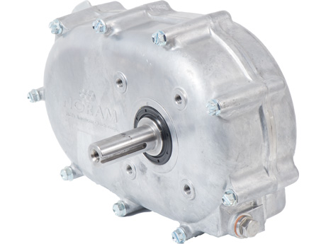 This "2-to-1 Gearbox with Centrifugal
Clutch" illustrates the initial sort of production transmission box
concept I have in mind.
This "2-to-1 Gearbox with Centrifugal
Clutch" illustrates the initial sort of production transmission box
concept I have in mind.
The centrifugal clutch would be dropped and there would be two side by
side enclosed spaces:
the chain drive and differential or planetary gear in oil, and the
variable conversion section in air.
We might thus see something like a flat mounting plate between the two
case halves, and a somewhat fatter unit overall.
For small initial production perhaps the entire case could be made from
flat aluminum pieces(?)
In addition to the input and output shafts, there would be a "shift"
lever to smoothly vary the reduction ratio,
which might vary from (eg) -20:1...0...20:1...7:1...3:1 ... from slow
reverse - idle - slow - faster - fastest.
[
http://www.princessauto.com/en/detail/2-1-centrifugal-clutch-gear-box/A-p8676199e
]
Perhaps approaching a company that already makes gears and
things might be a better approach than manufacturing from scratch?
In the meantime I started thinking about how one would
actually produce the transmission. Shafts, bearings, sprockets and
chains are easy to buy. The main gear (differential or planetary) will
be a special order product and probably costly. I am also concerned
about continuing availability. I don't want to design a product around
something that then becomes unavailable. I can't use Sprint/Geo Metro
car
parts! But if I can find something ready-made, that might be the best.
Large, strong variable width CVT pulleys and belts for
them would also be a custom product, and might well have to be made.
Expanding barrel pulleys would doubtless be better, but of course so
far there's no such thing. They would definitely have to be made.
That would make a typical oil immersed chain and gear
section. That would be fine, but it would be great, I think, to make
one that doesn't need
to run in oil. That would mean using a toothed belt drive in place of a
chain drive. These exist but are much less common and standardized than
chains and sprockets. It would also entail making the main gear, one
having plastic elements meshing with the steel ones, eg, plastic planet
gears between ring and sun gears. It would also mean making the gears
much larger, increasing both diameter and width, to reduce the loads at
all points so these lighter components wouldn't wear out.
One might expect that this type would be the more
difficult to create, but an oil bath case type has to be carefully
sealed. And if the gear does have to be made (can't find a suitable
gear, or if it's very costly), the big one with plastic might well be
easiest, because the steel components wouldn't need case hardening,
which would not be trivial to do. And, with the barrel type variable
section, it should have very low losses. An aspect militating toward
making gears is that the smaller the diameter of the sun gear compared
to the others, the faster it turns and and the lower the torque to
match the other gears. The size of sun gear will have a lot to do with
the size and strength required of the variable pulleys, which as
applied directly to the car's differential would appear to have to be
impractically large and strong.
On the 28th I looked up "how to make gears" on youtube and
came up with needing a "dividing head" and "involute gear cutters" to
make simple spur gears, of which there seem to be a fairly small number
of standard tooth sizes. "King Canada" tools (Chinese), had "rotary
tables"
(vertical and horizontal) and "dividing plates", apparently to make
them into "dividing heads". This was starting to look like 1000$ to get
started. Not surprising I suppose. Doubtless better than paying
1000-2500$ for each large and less than ideal planetary gear! Plastic
gears would cut easily and
quickly; steel ones slowly with wear to the cutter. The next day I
ordered a 6" table and its dividing plates at a local store.
Of course for production, it could be set up with CNC for
automatic production. In fact... what if I used a stepper motor and CNC
in the first place? The stepper motor could be geared down to turn to
thousands of of exact angles. It might be then (eg) 37 steps from one
tooth cutting position to the next, and all would come out even at the
end of the circle. I might not need to buy and set up the "dividing
head" at all? But I'd probably have to make appropriate gear sets for
the stepper motor first! And the "rotary table" will no doubt be useful
for
pulleys, too, so the 500$C order stands.
On the 30th I found a set of eight "M4" involute gear
cutters with "20° pressure angle", apparently the most common, via
aliexpress.com . Depending on the gear diameter, the teeth - or the
spaces cut out between the teeth - need
slightly different shapes. A set of eight cutters covers from 12 tooth
gears up
to 135 tooth plus "rack", a straight line gear. I hope "rack" will
cover a large ring gear with inside teeth as well. There were various
ones to be had from North American sources, but they weren't in sets
and they cost more. This set looked like it'd be around 300$C by the
time I had it. The center bore is apparently 27mm (the specs are
actually a little sketchy), which is going to
take making a very fat shaft to fit it onto the milling machine.
Configuring
The components could probably take a higher speed than
might be dealt to them with most electric traction motors. Higher speed
would be less torque, and less torque means smaller components. So
perhaps (with a differential gear) it would be well to make the
transmission variable between zero
(even less for reverse) and 1 to 1, and have all desired fixed
speed reduction ratio follow with a fixed gear, chain or belt, to be
determined by the application. For example in the Sprint, there would
be a reduction of 3 between the new transmission output and the
original differential (again driving both wheels) to get the 3000 motor
RPM to 1000 wheel RPM on the highway. Any variable higher reduction
would be available for lower speeds. And the torque the transmission
needs to handle is 1/3 as much as trying to drive the differential
directly - those V-belts might not have slipped!
Then, to use a planetary gear could further increase the speed
and decrease the torque of the variable drive component. The highest
speed element is the sun gear, so that should be where the variable
drive connects. I considered that since the two drives were turned the
same way, the sun gear and the planet gears would be the inputs, since
the ring gear would be turning backwards. But if a pair of big gears
(one metal, one plastic) tied the drive shaft and the ring gear
together, it would turn backward compared to a chain (or belt) drive,
as well as eliminating it. Then the sun gear would be the variable
element and the planets carrier the output. One would then see the ring
gear with teeth on the outside to connect with the drive shaft gear, as
well as on the inside. It would be a naturally compact arrangement:
shorter, slimmer and lighter. Of course, larger plastic gears would add
bulk.
As I was finishing this newsletter on September 2nd, one
last possibility occurred to me for modifying the present configuration
on the Sprint so that it could work, rather than creating a whole
production unit first: I could add a gear or chain drive onto the left
side of the differential to change the pulley system drive ratio, and
hence increase the speed and reduce the torque of the variable belt
section as desired. Different variable section ratios could be tried
out by changing chain sprockets and ratio. Perhaps the Sprint could be
running this fall after all!
Double Barrel
Variable Torque Converter - Conceptual Improvements
I thought up this variable torque converter, two
oppositely varying diameter drums and a flat belt, a couple of months
ago, as a highly efficient replacement for the variable width angled
pulley type. But I wasn't very serious about it. I had serious
reservations about
actually trying to make what I was visualizing, especially for any
high-torque purpose. Then it started to look like it would be valuable
for the infinitely variable transmission, so I started coming up with
ideas to start making it sound more practical.
I had conceived of the surface of what would usually be
some sort of pulley as being "barrel staves" that would expand outward,
so that the barrel would become larger in effective diameter, with
spaces between the staves. The concept seemed good, but it sounded like
it would be inherently flimsy. How would one make that robust?
Perhaps it might attain strength via some novel attachment
mechanism within. Then I started thinking of the staves as hinging from
the leading or trailing edge. In order that they will have as much
surface as possible contacting the belt, but with the belt not going
over a sharp edge as the segments swing up, the unhinged face would be
more curved. They might overlap the next segment. This probably has its
limitations, but the segments would definitely be intrinsically
strongly held on by the hinges.
OTOH... if the sides of the staves had thick sides and ran
in and out via slots in sturdy side plates, it might be plenty strong
enough. Especially if the pulley was narrow. How about fat "pie" pieces
rather than thin "staves" just on the outside?
The design definitely bore closer investigation with the
idea of creating a working prototype.
Another idea or two is belts: A poly-V-belt might replace
a flat belt if the staves have the appropriate grooves. Perhaps a
toothed belt isn't outside the bounds of possibility. The constraint,
and it's a big one, would be that the staves would have to "click"
expand in unit tooth-length increments, not smoothly varying, in order
that the belt teeth wouldn't jump the grooves. Uneven tooth spacings
between segments might still work for a time, but the belt would jump a
bit at each change of segment, and so the teeth would probably start
wearing down rather rapidly. (Or might the belt itself push the
spacings closer or farther to mesh properly, expanding or contracting
the diameter by a tiny amount where they come together to do so?
Perhaps this idea merits more thought?) With a toothed belt, the belt
might be an inch wide or less and still have excellent grip on the
pulleys without excessive pulley tension.
Then for the above article I conceived of using two belts
side by side, and that could apply here as well. Surely two or three of
the nice poly-V belts (I saved the package in case I wanted another one
the same!)
would be better than a variable width pulley system using pulleys that
are too small diameter with belts that are too narrow, and hence just
slip like the V-belt? And so the Sprint variable transmission project
and this new idea are beginning to merge.
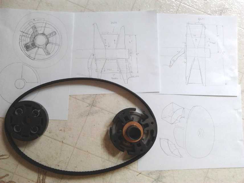
Two centrifugal clutches
with a belt to illustrate the expanding pulley idea, and some
sketches
I conceived that if two identical pulleys could expand out
to 1.5x their closed diameter, oppositely, the range of ratios between
1.5 to 1 and 1 to 1.5 would be 2.25x difference, just what was required
to go everywhere between a moderate reverse and "full speed ahead". In
order to get there, a 2" radius (eg) had to be able to expand to 3",
with a 1" in-out travel.
On the 30th I got out a centrifugal clutch. It had the
basic elements:
four quarter circle "staves" that could move in and out. But not very
far. After drawing a few things on a piece of paper, I came up with
some pieces of a plan. The pulley base could be a stiff, strong metal
spool. The sides would cover the edges of the
pulley - would be the edges of the pulley even when it was
fully
expanded. In each end would be 4 slots running from near the middle to
near the outer edge. Into this spool four 'tall pie' 1/4 circle pieces
of plastic would fit, with the inner corners cut out where the pipe
'axle' was. From near the inside and near the outer rim of the pies,
two threaded rods would go right through, sticking out both ends into
the slots in the spool sides. A metal slider piece would go over the
ends of the bolts, to slide the pie piece in and out on the slots, by
that 1" travel.
A linkage would connect the slider pieces to a
'washer' on the shaft. As the 'washer' moves back and forth on the
shaft, the pulley would expand and contract. The exact form this might
take was still only hazily defined.
On the 31st I thought of
another improvement. Instead of straight sides and a pipe axle on the
input pulley, they could be tapered sides, like the variable "CVT" belt
pulleys, and the center pipes would protrude outward, leaving these
tapered end pieces free to slide in and out on the drive shaft. The pie
piece ends could match these angles. When the ends were pushed
together, the pie pieces would be forced outward to a larger diameter
(per above sketches). Springs would pull them in so when the lever let
the ends move apart, the diameter would contract. Here then just might
be the last piece of the puzzle - a good way to change the expanding
input pulley's diameter from the shift lever. The next day, I started
thinking that the pulleys shouldn't shift their position as the
diameter changed - they should stay exactly in line. The idea could
still work, but the moving end would have a greater angle, and the
fixed end would be vertical so that the "staves" would stay in line
with it. (Now I understood why some CVT belts have one vertical side
and one angled instead of being symmetrical!)
The output pulley is different, needing no external
control input. It can still be the "spool" with slotted straight sides,
spring loaded to push the "staves" or "pie pieces" outward, oppositely
to the input pulley diameter, which also applies the required belt
tension.
Finally, I had the idea that since the belts aren't
intended to slip at any time, but since they can't be toothed belts,
one might make the pulley faces textured, or regardless cut in 'teeth'
something like toothed belt pulleys, to help give them more traction to
prevent belt slippage, especially if used with textured belt surfaces
such as with the belt I have.
Electricity
Generation
Oscillating
Water Column (OWC) Ocean Wave Power
Buoy
The Turbine
If one is going to the trouble of putting together buoys
or other units to be deployed in rough waters and electrically
connected to the shore, it would seem only sensible to get the largest
possible output from each one. If one buoy was 40% efficient, it would
have to be twice the size of one that was 80% to produce the same
output, and obviously more costly and harder to work with. One major
component in this efficiency will be the turbine.
In considering what form of turbine or propeller to use to
make rotation
from the air being exhaled and inhaled by the buoy, I looked at the
unsatisfactory 'wells turbine' types of bidirectional designs, and
thought of directing air with louvers or flaps so that it would pass
the vanes from the same direction regardless of whether the buoy was
inhaling or exhaling. But that seemed to add unnecessary bulk and more
moving parts to the system.
The idea then occurred to me to have two propellers in the
airstream, one for inhale and the other for exhale, both made to turn
the shaft the same direction. These would have cogs to the shaft so
that the one not pushing in the right direction would simply slip.
Evidently there are "one-way bearings" which sound ideal for the
purpose.
And perhaps free spinning rotation of these blades in the
wrong direction would be blocked by one-way cogs to stationary. A two
or three blade propeller not turning in the airstream would have little
effect on it compared to the one that was spinning. And if the cogs
were arranged to stop the blades right behind the supports for the
generator and axle (needed in any event), they would still less affect
it, relatively speaking.
At first I thought that the 12" plastic propeller I had
from the diver's propulsion unit, or segments with the same profile,
would be ideal. Then I remembered that windplant propellers are mirror
image to propulsion propellers. I could still copy and mirror the shape
manually.
Later it occurred to me that if the one propeller was
freely spinning backwards, it would still have little effect on the air
flow. Only a propeller driving a load slows the air.
But in searching I ran into "Tesla turbines", yes,
invented by Nicola Tesla. These interesting turbines have no blades,
but closely spaced disks, and they force the input air into a
decreasing spiral pattern that exhausts from near the center. On the
9th further searches on the web disclosed more
about Tesla turbines, and even a place that had tiny ones for sale,
with tiny motors for generators, for 75 $US. In order to study the
whole concept further I ordered one. In addition to reputed very high
potential
efficiency, these are very compact, handling ridiculous amounts of
power for their size, at ridiculous RPM.s. But the best efficiency
evidently is gained when they're not driven too hard - just as should
be the
case with the OWC buoy. Made from plastics, they would be very
lightweight.
On the same website they had the "Tesla valve", a device
with no moving parts that lets air pass through freely in one direction
but with great difficulty in the other. In one direction the air has a
clear path. In the other it keeps hitting loops that each turn some of
it around and deflect the passing air from the straight path toward
the next loop. It was said that it was 40 to 200 times harder to blow
air through it one way than the other, depending on how many loops
there were, 4 to 11. I was very surprised to see such amazing figures,
since there's clearly just as much room for air to pass through in
either direction.
Again a small one was for sale. Since one idea was to have
flaps or louvres to direct air, I ordered one of these too, for 25 $US.
I still question whether the unit is freely scalable or if it works by
boundary layer effects like the turbine, in which case it might not be
very effective when scaled up to a size useful for large OWC buoys
unless it has many tiny convoluted surfaces. I still can't quite
believe it could be so effective, but if everything works out, one
optimally configured Tesla turbine with four Tesla "solid state air
diodes" to make the air flow right for both inhale and exhale, might
just be the best answer, with the spinning turbine being the only
moving part.
In theory the output air could be directed to a second
stage Tesla turbine if there was much energy left in the air to
extract... Or does the single turbine act like multiple stages all by
itself?
One fault of the original Tesla turbine is said to be that
it doesn't have much torque until it gets up to near its synchronous
speed for the input air energy. On the 10th I had the thought that,
while everyone tries
to make the Tesla turbine plates smooth, one person used some stator
laminate plates from a stepper motor (indeed he used the whole motor
for the turbine - case, bearings, shaft, laminates), and staggered the
slots, making a helical opening through the plates, which he thought
would give it extra torque at lower speeds. So then... the air would
grab better on a rough plate than a smooth one? Once it was up to speed
roughness or slots should make little difference. Until then, roughness
should give it more torque. This makes me think of using my rather
coarse, lumpy 3D printer to make the plates. Wouldn't that be simple
for production!... if they didn't fly apart.
Another interesting idea would be plates with a spiral
shape ridge on the surfaces, the shape of the path the air is supposed
to take, perhaps with no plate gaps between the spiral ridges at all.
These seem like some very promising variants, and once having a case
and bearings, it should be easy to print various rotors and try them
out. And with an air compressor and gauge on a test bench and driving
the same generator driving the same electrical loads each time,
performance differences should be easily determined.
The Tank - and Air Duct, Turbine, Generator?
On the 2nd I cut the bottom off one of the hot water
tanks with the angle grinder. It went easily and didn't quite wear out
one zip/cutting disk. The next question was what to cut out at the top.
Should I simply cut a square for a computer fan (or two back to back?),
or do something more ambitious, perhaps with the 24V lawnmower motor?
But I started to worry that the brushes in the motor would make for an
undesirable mount of friction. Maybe an alternator, converted to
permanent magnet armature, then?
Then I thought that, whatever, for initial testing the
first tank should probably have a series of removable covers to take it
from being a quite small opening to a fairly large one, and the air
velocities should be measured at different size openings - and ideally
in several different sizes of waves. If the air velocity could be
converted to a voltage, it could be charted for hours with a device
Tristan gave me 5 years ago. How could that be done? With a generator,
of course! With no load, it would have linear voltage output per air
speed and little resistance to the air. If I could hold up the
anemometer to the opening and get a reading or two, and also see what
the voltage was, they could be at least nominally correlated. I had
several computer fans from small to large to try out, so this suddenly
looked like just the thing to do. Smaller fans/holes should give higher
airspeeds, since the same amount of air has to come through regardless
of size - until the size is too small, at which point there would be a
significant damping effect, and not all the air will come out/go in
before the wave height reverses.
Then with a load on the generator - if any of the fans
could put out enough watts to make a difference - one should see the
damping and airflow reduction effects even with larger holes. In this
manner, one may start to get gross estimates of how much power to
expect from a buoy the size of a hot water tank, and what size
turbine/vent area to employ to get the most out of it. The operative
formula is that the power increases with the cube of the air velocity,
so the maximum air velocity that can be obtained under generator load
without choking off too much of the available air will give the most
power. (Why cubed? e = 1/2 m v^2, with
e=energy,m=mass,v=velocity, and 'm' of the air at 1.4
kilograms per cubic meter also increases with velocity as more cubic
meters of air go by in a given time.)
The bottomless tank measured about 46cm O.D. x 105cm long.
That's only about .16 cubic meters, or 6 cubic feet. And some of that
will be occupied with flotation foam. If the water rises and falls
about 1/2 way, that's .08 cubic meters of air that will be exhaled and
inhaled. .08*1.2Kg/m^3 = ~.1Kg of air mass. It doesn't seem
like much! (You'd think a "bottomless tank" would hold an infinite
amount!) All depends on the velocity and cross section of that air at
the turbine and the period of the waves. Other than that, obviously the
bigger the tank, if the waves can sufficiently fill and empty it, the
more the power. and the more tanks there are, the more power and the
more continuous (steady, even) it will be.
Changes of Approach
On the 8th I found some theoretical studies and tests
about 'OWC Buoy's in a web search. In fact there was a long list
of them in the search results. I could scan them all for good ideas and
estimating proportions. They're also good fodder for any investors who
might be interested: piles of supporting theoretical studies along with
any real world designs and tests we do.
From the ones I had a chance to look at briefly that
afternoon, I already decided on an important change. It seemed they
were all made like the one shown by the guy in LA, who wanted to use a
water turbine instead of air. That is, the flotation was all at the top
of the long tube, which was hence mostly submerged. This apparently is
called a "spar buoy". The bottom of the tube was supposed to be in
deeper, calmer water, and when it bobbed up, closely following the
crest of a wave, that was supposed to suck the water out at the bottom,
sucking in air at the top. Let's call this the "bobbing tube" approach.
My idea on the other hand was to have both flotation and weight at the
bottom of the tube, arranged so that much of the tube was sticking up
into the air. When a wave crest came along, the buoy would only slowly
rise. This would be the "stationary tube" approach. So the wave would
rise around the tube, and water would come in from the bottom to match
the outside level, forcing air out the top of the tube.
Probably either approach will work. I thought I was
getting away from inertia, but I wasn't accounting for the inertia of
the water itself, which is what makes the bobbing tube work. Guessing
by the fact that everybody else is using the bobbing tube approach,
it's probably better - even if it's only because it'll be
intrinsically easier to make it stay more or less upright in the waves.
The tube with no flotation will counterbalance the generator and
turbine on top. But I suspect it probably actually works somewhat
better, too.
One might improve the stationary tube design's performance
with some moving parts so that the water could enter through holes or
slots from just below the surface level, but these would (have to) be
closed to air from above the water line. That would minimize the
water's inertia by minimizing the amount of water being moved and the
distance it has to go. Maybe a telescoping tube whose bottom is always
just below the water line... But moving parts -- ugg!
So it seemed I should change the approach. This was still
trivial - no steps to undo - since I hadn't got any farther than
cutting the bottom out of the tank.
Next I had to decide how long to make the tube and how to
shape it. The bottom has to be well below the main wave action, and a
wider "bell bottom" opening seemed to be how others are doing it. I
figured I might try it with just the hot water tank tube, then with a
bottom flare screwed on (making it longer, too).
Then I hit on a second modification to the approach.
Everybody's buoys were vertical. But waves strike at an angle, and
their forces act at an angle. In videos I saw the buoys tip at each
wave
crest. If the buoy matched the wave angle, or at least came closer to
it than vertical, as it lightened inside by inhaling air, the whole top
end (ideally) should virtually pop out of the water (more) just when
the wave
crest has passed, giving it that much longer to inhale and then that
much longer and more air inside to exhale with that much more force on
the descending part of the cycle.
However, on later reflection I realized that tilting the
buoy very much brings the tube bottom closer to the surface, so the
suction effect from it being in calmer, deeper water will be less. I
tried drawing a "bent" buoy, but that would resist up-down motion more,
and any angled buoy might tend to twist around and face the wrong
direction in the waves. By the end of the month I had little conviction
that the idea would work as well as a straight vertical buoy. Crests
are only a brief part of the wave, even if the most energetic part.
Even a vertical buoy should pop out decently at wave crests, and
simplicity has advantages. However, here is a drawing.
Buoy to tilt as wave crests approach, to take
advantage of the
horizontal component of wave force as well as the vertical.
But I'm not confident about the efficacy of this approach.
Then I started thinking about the weight of the water tank
and how hard it could be to carry it, handle it, and to position it out
in the waves, with a long stick from standing on the rocks (latest
strategy - I know a deep wavy spot next to a point of rock), and keep
it where it was wanted. I started to
think about the turquoise piece of 30cm PVC pipe, still just 3" shorter
than the hot water tank even with all the pieces that had been cut off
it for doing motor cases. It might only be 1/2 the volume of the tank
of less, but it was also 1/2 the weight at 31 pounds. Or maybe I should
go for something even thinner than that, something very easily handled
and thrown out into the water, using the electrical and data
transmission
cords for a rope?
The Generator
I started out thinking that the 24 volt lawnmower motor
would be a good generator, but as a DC generator it's not a very
powerful one. Then I started thinking that the brushes seemed to have
quite a bit of drag. Like the sticking brake on the Sprint, that might
reduce the output by enough for low power but promising results to look
needlessly
dissapointing. In the micro hydro video linked last month, the maker
had converted a car alternator to brushless. And I had heard of that
idea before. There were some videos on youtube about it. The two main
components are of course the rotor or amature, and the stator.
The usual conversion seemed to involve replacing
everything but the case and bearings. A new armature covered in FeNdB
supermagnets facing outward is used. But why couldn't the coil simply
be replaced by a big neo ring magnet (ideally the same size and shape
as the coil) in the same armature?
Then, it seemed that usually the stator was replaced with
one having more turns of finer wires - that must be either to use with
24 or 48 volt systems, to run at lower RPM.s, or because the field
magnetism was weaker. I doubt the magnetism from neo magnets is weaker
than the coil's, so that means it's for lower RPM.s or higher voltage
systems. With a small diameter turbine in the wave buoy, it would have
high RPM.s. Surely if one was running the usual sort of RPM.s for the
alternator and wanted a 12 volt system, no change to the stator would
be needed?
Thus presumably, conversion of a car alternator to a
permanent magnet alternator should simply involve disassembly and
removal of the brushes, disassembly of the armature, replacement of the
ring coil with a suitable neo ring supermagnet, and reassembly.
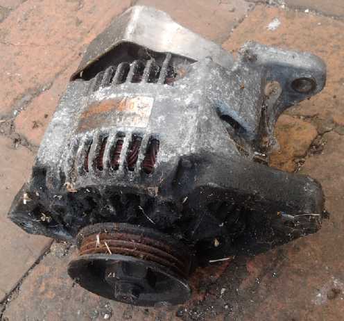 On the 5th I
remembered I already had a small alternator,
removed from the Sprint car. I dug it out from the Sprint parts bin.
Even with its field brushes it spun much more freely than the mower
motor. I spent the afternoon disassembling it, and part of the next day
getting the armature parts off the shaft. There were some challenges to
these operations. The stator stuck fast to the wrong half of the
housing and I had to disconnect the wires to avoid ripping them out.
Luckily the wires unscrewed from the outside, and when bent straight
could be pulled through holes. Then, it took 6 tons of pressure in the
hydraulic press to get the armature parts off the shaft. I didn't put
that kind of pressure on it on the first try and I looked for some
other way, but finally I figured if the shaft bent or something broke,
I would just have to go buy some other alternator, which was no worse
than if I couldn't get it apart. It finally came loose with a mighty
"crack!" and after that it took no more than 3 tons(!) to move it to
the end of the splined shaft.
On the 5th I
remembered I already had a small alternator,
removed from the Sprint car. I dug it out from the Sprint parts bin.
Even with its field brushes it spun much more freely than the mower
motor. I spent the afternoon disassembling it, and part of the next day
getting the armature parts off the shaft. There were some challenges to
these operations. The stator stuck fast to the wrong half of the
housing and I had to disconnect the wires to avoid ripping them out.
Luckily the wires unscrewed from the outside, and when bent straight
could be pulled through holes. Then, it took 6 tons of pressure in the
hydraulic press to get the armature parts off the shaft. I didn't put
that kind of pressure on it on the first try and I looked for some
other way, but finally I figured if the shaft bent or something broke,
I would just have to go buy some other alternator, which was no worse
than if I couldn't get it apart. It finally came loose with a mighty
"crack!" and after that it took no more than 3 tons(!) to move it to
the end of the splined shaft.
Since no one else seemed to have converted a car
alternator in this manner, I took footage to do a video about it for
youtube in case it was successful. Then I found one done this way on
youtube, titled Modificaciòn de Alternador a Generador
Eléctrico. (I seem to be running into a lot of interesting
things in Spanish lately!) Unfortunately I couldn't understand a word
so I don't know what they said about it, but it had 2 or 3 ring magnets
to make up the desired size. They seemed to be using speaker magnets as
ring magnets.
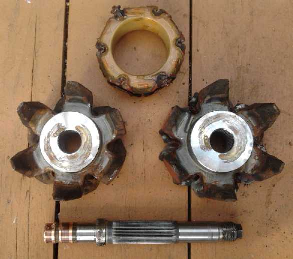 One disconcerting thing was that the hub in the center
occupied more space than I had expected. (Those silvery center areas
stick out, and touch each other when assembled.) the coil was about
40.89mm
I.D. x 58mm O.D. x 24mm wide. There were two ways to go: I could find a
rather fine ring magnet with a large center (ie, the shape of the coil)
to fit those dimensions, or
else I would need to turn down the diameter of the center hub on the
lathe, both halves, so it would hold a ring magnet with a smaller inner
diameter. A search found only a 2" OD x 1" x 1" magnet anywhere close
to suitable, so I'll have to do the turning down. And it's a scary
magnet: at 180 pounds pull it's more than I like to handle. With
shipping and conversion from $US to $Canadian, the 23$
magnet4less.com magnet became about 70$. And that was before taxes and
"brokerage" collect charges. It now looked more like a 100$ order.
Indigo.com in Canada didn't have any that large. I went to
Aliexpress.com, but the search couldn't be narrowed down by size, and
after a while of looking through a maze of otherwise unsuitable magnets
of 50mm diameter, I gave up and ordered the first one. It arrived about
the end of the month.
One disconcerting thing was that the hub in the center
occupied more space than I had expected. (Those silvery center areas
stick out, and touch each other when assembled.) the coil was about
40.89mm
I.D. x 58mm O.D. x 24mm wide. There were two ways to go: I could find a
rather fine ring magnet with a large center (ie, the shape of the coil)
to fit those dimensions, or
else I would need to turn down the diameter of the center hub on the
lathe, both halves, so it would hold a ring magnet with a smaller inner
diameter. A search found only a 2" OD x 1" x 1" magnet anywhere close
to suitable, so I'll have to do the turning down. And it's a scary
magnet: at 180 pounds pull it's more than I like to handle. With
shipping and conversion from $US to $Canadian, the 23$
magnet4less.com magnet became about 70$. And that was before taxes and
"brokerage" collect charges. It now looked more like a 100$ order.
Indigo.com in Canada didn't have any that large. I went to
Aliexpress.com, but the search couldn't be narrowed down by size, and
after a while of looking through a maze of otherwise unsuitable magnets
of 50mm diameter, I gave up and ordered the first one. It arrived about
the end of the month.
Then I realized the whole metal center needs to go,
leaving just enough to hold the magnet - the full bar inside the magnet
would short out its field.
I was hoping this simple sounding conversion would be in
the "simple home DIY" category. Unfortunately both the hydraulic
pressing and the required lathe work tend to take it out of that
category, as well as complicating it and making it time consuming. And
100$ for a single magnet to put into it hardly makes it economical.
(Maybe I should have just cut up some 2" x 1" x .5" rectangular magnets
on the angle grinder and stuffed in the pieces?) Or perhaps I should
have
been looking to see if there are today more cost effective permanent
magnet alternators on the market than there used to be.
Next thing to find out is how well it works. It could
hardly ask for a stronger single magnet. Hopefully it'll put out 250
watts or more at useful voltage, current and RPM, which is doubtless
more power than can be had from a hot water tank wave power unit even
at peak air movement times, much less continuously.
An old (2005?) alternator
experiment. The old rotor with its petals being long gone, it'll
need a new one with supermagnets around the outside. And the coils will
need reconfiguration.
But the main case and parts to make a permanent magnet generator are
there.
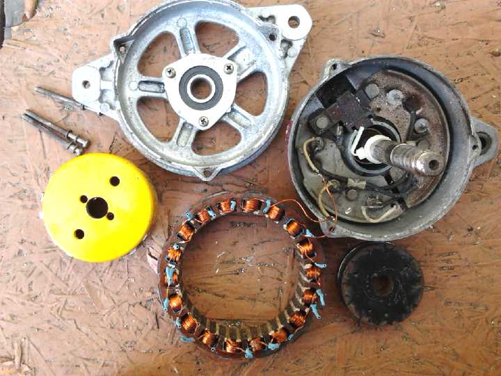 Looking for something in my
garage on the 12th, I
discovered another old alternator. Changing the rotor and rewinding
this had been one of my first experiments in motor work in about 2005.
I hadn't looked for it because I thought I had given it to someone long
ago. Much needs changing and the original armature is gone leaving only
the axle, but with supermagnets added and some wiring changes, it might
also be made to work well enough to be a generator for a second wave
power test tank or other generating task.
Looking for something in my
garage on the 12th, I
discovered another old alternator. Changing the rotor and rewinding
this had been one of my first experiments in motor work in about 2005.
I hadn't looked for it because I thought I had given it to someone long
ago. Much needs changing and the original armature is gone leaving only
the axle, but with supermagnets added and some wiring changes, it might
also be made to work well enough to be a generator for a second wave
power test tank or other generating task.
Recording Test Equipment
By the 7th I started worrying more about what would happen
during testing. If I only got a glimpse of what was happening and had
to remember a bunch of rapidly accumulating readings, it would be hard
to quantify test results. One would really like to record output
performance moment by moment, along with recording the wave heights and
all
other relevant parameters causing that output. If everything was being
automatically recorded, the testing process itself would be much
smoother, faster and simpler, with detailed examination and analysis
later indoors. One might test a configuration in low,
medium and high wave conditions (by moving the buoy around into more
and less sheltered spots), in the same time as doing one test with
hastily jotted down and unsatisfactory manual readings.
The recordings would allow later detailed comparisons, say
with a different type of turbine or a different generator
configuration, to see which one really performed better under real
world conditions. Turbine "A" might work fine and we were thrilled with
it during testing, but why manufacture it if turbine "B" gives 15% more
output from the same buoy?
Among the candidate measurements would be:
- Air temperature (read once or occasionally during test)
- Water height on a stationary "stick" near the buoy to get the wave
heights
- Water column height inside the buoy
- Water column height on the outside of the buoy (maybe even on the
front face and the lee side)
- Airspeed entering and exiting the buoy (at first without turbine
attached and with various test sizes of entry/exit holes)
- Air pressure at the same point
- Generator/turbine RPM/frequency
- generator voltage
- generator current (various loads may be turned on and off)
- Camcorder visually recording actual motions of buoy
It dawned on me that setting up equipment to measure the
vital parameters will doubtless take more design and setup than the
test buoy itself. But it only needs to be made once and then can be
used on future buoys.
I decided that the way to do it would be to use the same
MSP430G2553 microcontroller that I have in mind for other projects.
This would mount in the generator compartment on the top, out of the
spray and salt. It would connect to the various sensors and be
programmed to record every reading several times a second. It's
somewhat equivalent to instrumenting a space probe. It could either
send the readings to a computer on shore in real time by wire, or
simply store them for later retrieval.
I think some of the sensors will take some creative
design, and the readings will be numbers that will have to be
calibrated to some useful units. I can see the path from beginning to
end, but overall this is a project that one would allocate several
solid months to build, and once again I must ask myself: when
I am going to find the time? I think it's unlikely to get there without
funding to draw in some additional talent.
Trouble at the Pass
After lavishing all the above attention to the project,
toward the end of the month a remote waterfront property that had a
nice house with a huge workshop, was sold. There I had thought we might
quietly develop and thoroughly test the wave power components and
systems for a couple of years, refining everything to reach "well
tested and salable" product stage before "going public". The potential
investors hadn't decided to buy it or help me to buy it. I think that's
a shame, because unlike most money thrown into an R & D project,
the full value (and probably more - it was a bargain) could have been
recouped by selling it again. Probably the plan was either more money
than they had in mind, or just too "outside the box" for business
minded people, who also might well have considerably less confidence
than I about being able to effectively circumvent bureaucracy during
the experimental development and testing time with it, until we had the
solid time-tested data with development and improvement of the
units, that it seems no one has been able to get for want of fixed
access to the sea.
But it was really the only plan I could see that was
likely to succeed. One of the potential funders had visited
with wave power developers in Scotland - supposedly a "hotbed" of wave
power development - and had been told that government and supposedly
"green" "environmental movement" opposition was so bad in their
experience that we should give it up. With that advice and without the
unique place where I thought it could be done quietly, we all decided
to take the advice of the Scots. I said I would put no more of my
valuable unpaid time into it. In the meantime, as luck would have it, I
had after all these years of trying to make a variable torque
converter, come up with the Universal Infinitely Variable
Transmission
concept, which might well be far more profitable to investors anyway.
My
mind turned rather abruptly to designing with a view to making it a
potentially commercial product.
"GREEN" Opposition?!?
I suspect the so-called "green" opposition mentioned by
the Scots must have been people being paid to protest by vested
interests like petroleum and nuclear power. That this sort of outrage
is a common occurrence, foisted on us by some of the very richest men
on the planet who don't want change, is never reported in the news, but
it's gradually being uncovered via the internet, instance after
instance. George Soros's name repeatedly comes up for paying street
people to perform evil machinations, mostly political. For strong
protest to erupt "out of the blue", fast and hard against something
hardly known, in its early experimental stages, with the utterly
minimal environmental impact of wave power, and all the people who
would like to see us move toward sustainable energy sources, it's hard
to see how it could be otherwise. Consider how 'big oil' paid people to
create "Citizens Against EV Charging Stations" in California, as
revealed in the documentary Who Killed the Electric Car? The
few wave power experiments being done would be way beneath the radar
screen of real environmental groups trying to oppose real environmental
problems like oil pipelines and nuclear plants, let alone be seen as an
actual concern worthy of protest without even knowing what might be
developed and what its characteristics and effects might be.
http://www.TurquoiseEnergy.com
Victoria BC Canada