Turquoise
Energy Ltd. News #104
covering September 2016 (posted October 2nd 2016)
Victoria BC
by Craig Carmichael
www.TurquoiseEnergy.com
= www.ElectricCaik.com
= www.ElectricHubcap.com
= www.ElectricWeel.com
Highlight: Differential transmission concepts proven by
experiments, work progresses (see Month in Brief, Electric Transport)
Month In Brief
(Project Summaries)
- UIVT: from Sprint/Variable Transmission project - Conversion of a car
alternator to a permanent magnet alternator - Tesla Turbine Windplant
Concept
In Passing
(Miscellaneous topics, editorial comments & opinionated rants)
- World Nearly Loses an Inventor - Fruit Picking Pole Makes Picking
High-Up Fruit Safe & Easy - Tilapia update - The Ultimate Theft:
Private
Central
Banks
are
Buying
Up
the
Whole World with Money They Print Out
of Thin Air
- The Web of Conflicts of Interest of Officials, between the USA
Government
and
"Corporatocracy" - Canadian Parliamentary Voting Reform
Committee meeting - Honey Bee Ecological Catastrophe
- Improve Health and Increase Life Expectancy: Metformin
- In Depth
Project Reports -
Electric
Transport - Electric Hubcap Motor Systems
* Electric Hubcap motor, Chevy Sprint & Differential gear Variable
Transmission:
- Sprint Prototype with Third Shaft?
- Single Variable Pulley with Third Shaft - or Controlled Idler
Arm
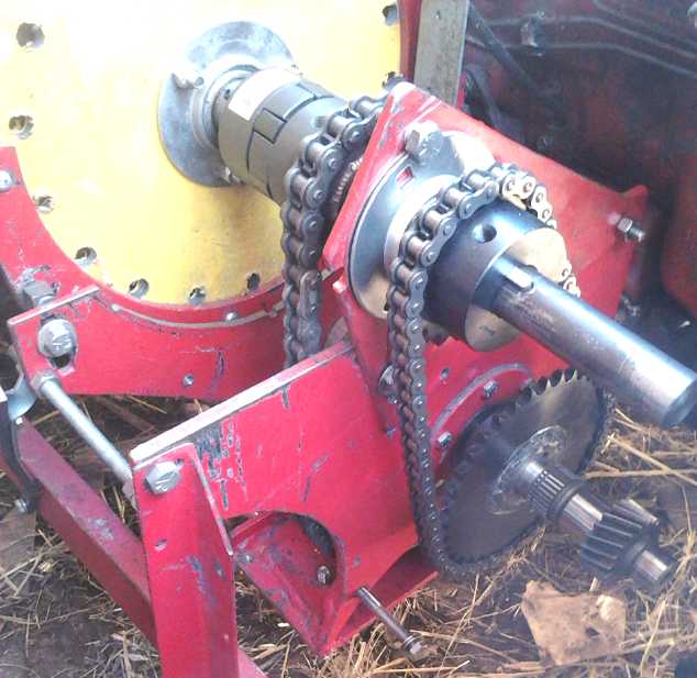
- Chain Drive Experiments/Tests
- Conclusions (proves concepts)
- Electric Hubcap Motor Troubles (Wiring)... & Electric Caik
Motor Upgrade
- Gear Cutters
- Gear Making Calculations
- Other ways to Make Plastic Gears!
- The Spur Gear Differential Gear Unit & Variants
- Configuring a Production Model
Other "Green"
Electric Equipment Projects (no reports)
Electricity Generation
* Conversion of a car alternator to a permanent magnet alternator with
a ring magnet
* Tesla Turbine Wind Turbine?
Electricity Storage - Turquoise Battery
Project (NiMn, NiNi, O2-Ni), etc. (no reports)
September in Brief
Between the experimental work on two projects that turned into
about four, news that seemed worthy of note or comment, a close
call with a bus, and meetings with Parliament's Voting Reform Committee
and a BYD electric vehicle demo, there seemed to be a lot to write
about this month.
A few days were spent in the first half of the month on
finishing
the conversion of a car alternator into a permanent magnet alternator
using a big ring magnet. It seemed to work quite well, but had more
magnetic friction than I had expected. (Owing to that friction, near
the end of the month I started thinking more favorably of the Hugh
Piggott frictionless air core axial flux generators for use in
electrical generation projects. The main components of these can be
purchased. I started coming up with improvements, especially my rotor
magnet strapping system, that might give these units higher power
ratings (+50% or better) by getting more cooling air flowing through
them.)
The alternator was interspersed with testing aspects of
the new
differential variable transmission, proving out the theory, which
became the sole focus when the alternator was finished and tested. And
that branched out into consideration of how transmission gears might be
produced and what types of gears to make.
I found more ways to make plastic gears in or inspired by
youtube videos, figured out what seems like a better way to do the
variable ratio belt drive part, and I found a differential gear made
entirely of spur gears instead of bevelled gears. It looks better, and
it would be easier to make. It's quite similar to my idea for a "double
sun"
version epicyclic gear, but the casing and construction illustrated was
far superior to my vague ideas. It would be thinner left to right than
any ordinary
differential gear type, making for the smallest - or at least thinnest
- "OEM" transmission.
Along with that work went repairing the
Electric Hubcap Motor that was running the Sprint test car. One more
time motor and controller troubles got in the way of the transmission
project. I found
frayed insulation causing a short, and a power wire connection that had
never been
soldered, that had somehow run reliably for 5 years since
making the motor until, I suppose, the short had stressed it.
But it still wouldn't run right, and to be sure whether it
was the motor or the controller, I decided to (at last) repair the
Electric Caik Outboard's motor so that I would have a second motor to
try out on the Kelly BLDC motor controller. That should have consisted
mostly of reassembling it, but if I was repairing it, I should upgrade
the magnet attachments so it could do 3000 RPM safely instead of just
2000, which would be much better for the boat. So that project got
underway - much belatedly, really, considering the last boat trip and
the incident were August(?) 2015. It was the lure of making potentially
better motors - unipolar PM, switched reluctance and 'permanent magnet
assisted' - that had initially stopped repair, but those projects have
now
themselves been on hold for some time, without having brought motors
and controllers that really perform well so far.
One day in there an inattentive bus driver ran me, not off
the road, but over the centerline into the oncoming traffic lane. I
swerved in time not to be crushed by the bus, but if there had been a
center divider or any oncoming traffic, #103 might have been the last Turquoise
Energy
News. I wrote this incident up in In Passing to try
and help clear it out of my mind.
On the 18th I conceived of doing a Tesla Turbine Windplant
with a "horn" facing the wind to funnel air into it. This seemed to
have the potential for making more power per wind frontage area than
any other type, with Tesla's clever invention potentially beating the
"Betz limit" by virtue of effectively having multiple turbine stages in
one stage, and thus transferring most of the energy and reducing the
windspeed to "not much" at the outlet. It would also have no spinning
parts on the outside, making it safe for birds and near people, and
probably quieter. But my mini Tesla turbine still hadn't arrived at the
end of the month.
I ended the month on the 30th by going to a second meeting
about BYD ("Build Your Dream") and getting a ride with the other
attendees on the electric bus they had brought to town. On part of the
route, an electric Nissan Leaf was right in front of us.
It seems humorous that I walked to the venue, and at an
intersection the electric bus pulled actually up and stopped beside me.
I stuck out my thumb and called "Going to BYD?" But it said BYD on the
bus and the driver didn't catch on. Maybe if I'd called "Going to 360
Harbour Road?" he'd have realized I must be an attendee and opened the
door. But as he turned right and pulled out next to me I really noticed
it: No roar! No stench! The bus has a 300Km range and recharges in 3
hours from 480 volts at up to 100 amps.
BYD makes their own lithium-iron phosphate batteries.
Their philosophy is never mind getting the best or ultimate battery
specs - just make them as reliable as possible and to last as long as
possible. A friend attended who I wanted to exchange the latest with.
He suggested coffee, and somehow I forgot to check out the 5 ton
electric truck and electric car they had also brought. I also neglected
to take any pictures of the event.
If things go as BYD is planning, they may sell more
electric cars in the next 3 or 4 years than everybody else has up to
this point. And hopefully quite a lot of buses and some trucks.
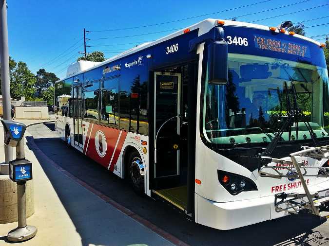 A BYD Electric Bus in California
And I don't know what would stop them from building a
similar version with railway wheels for passenger and commuter service,
other than having to stop for charging several times per day. Of course
strategically placed sections of line with overhead wiring could solve
that problem: they could use grid power and charge while travelling.
After, I went straight to my other destination, Mac's Auto
Electric, and bought a 5-Vs poly-V belt pulley that matched the belt I
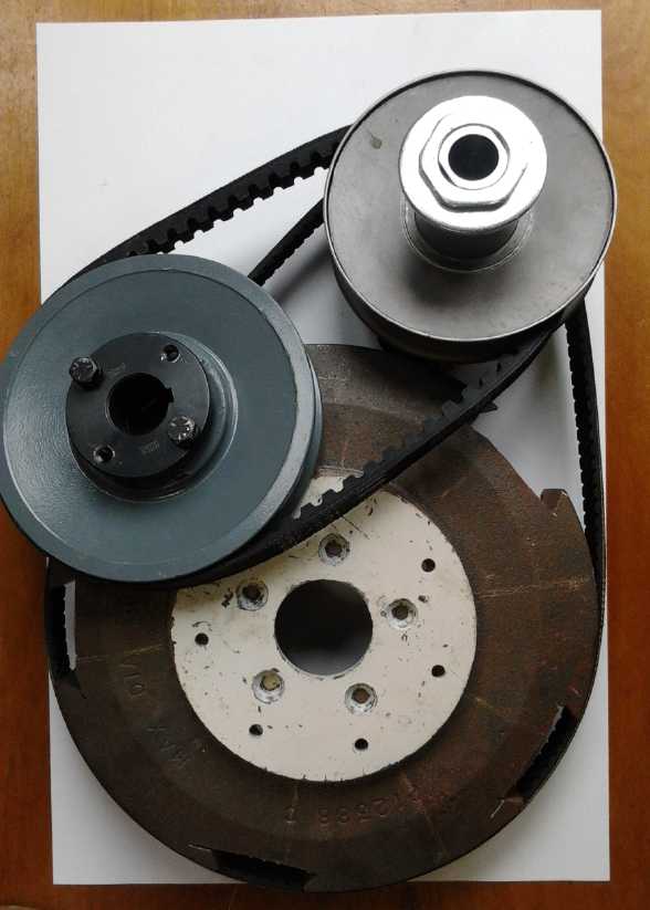
had, for the production prototype of the differential transmission.
THE UNIVERSAL INFINITELY VARIABLE TRANSMISSION (UIVT) - Chevy
Sprint/Variable Transmission project
Experiments with two chain drives proved the
differential drive principle, yielding
forward and reverse and reduction ratios that varied greatly, with only
slightly
different size sprockets.
 Having
established the principles of an infinitely variable
torque converter or transmission, I tried in August to prove them by
running the
differential drive with simple fixed ratio pulleys, but mostly the belt
just slipped,
showing that for high torque, very hefty builds are necessary. For
September I decided to try the same experiment with a chain and
sprockets.
Once the problems were (for the most part) worked out this (mostly)
worked. I found that 9 to 1 from
the motor to the wheel was still a pretty high ratio for getting
moving, which surprised me somewhat. It would be a good "second gear"
from about 10 to 30 Km/H.
Having
established the principles of an infinitely variable
torque converter or transmission, I tried in August to prove them by
running the
differential drive with simple fixed ratio pulleys, but mostly the belt
just slipped,
showing that for high torque, very hefty builds are necessary. For
September I decided to try the same experiment with a chain and
sprockets.
Once the problems were (for the most part) worked out this (mostly)
worked. I found that 9 to 1 from
the motor to the wheel was still a pretty high ratio for getting
moving, which surprised me somewhat. It would be a good "second gear"
from about 10 to 30 Km/H.
Then I bought another sprocket that made for both a higher
reduction ratio (-16 to 1) and a
reverse drive.
That is, the motor had to turn backward to move the car forward. Since
the motor turns equally well either way this
is of little consequence except internally to the gears.
With the
greater reduction ratio the car should have started moving easily on
the rough lawn, but with the high tension the chain, not pefectly in
line, jammed up. This effect in milder form probably also contributed
to the 9 to 1 not moving the car upslope more effectively - smoother
should run better.
The tests did however prove the differential drive theory
(in case there was any doubt). If the free left end of the differential
wasn't driven, it would turn twice as fast as the center drive and the
right car wheel wouldn't turn. Since the differential center drive had
a 3 to 1 speed reduction from the motor in its chain drive, a left side
reduction of 1.5 (to 1 - twice as fast) would produce "idle" and the
car wouldn't move. The lower sprocket I put on the differential right
had 36 teeth, so a 24 tooth sprocket at the motor shaft would give
"idle". With the 20 tooth sprocket (left end chain ratio 1.80) the
ratio
between that and the 3:1 drive of the other chain to the center of the
differential made for a final drive ratio of 9 turns of the motor for 1
turn of the wheel. The 26 tooth gear (ratio 1.385) gave a final drive
of -16
to 1, in other words being less than 1.5 it ran the car in reverse, and
being closer to "idle" than the 20 tooth sprocket it gave a
higher final reduction ratio.
Adding the variable drive and not having its belt slip, to
make a working "infinitely variable" torque converter or transmission
will probably be the largest challenge, but some ideas to help do that
have emerged.
As the month went on, I got
gear tooth cutting wheels and started putting together my conception of
a production unit. I layed out components (not all the actual ones I
would use) on a piece of 11" x 17" paper and started sizing things up.
 Laying out components and sizing things up for
a production unit.
Laying out components and sizing things up for
a production unit.
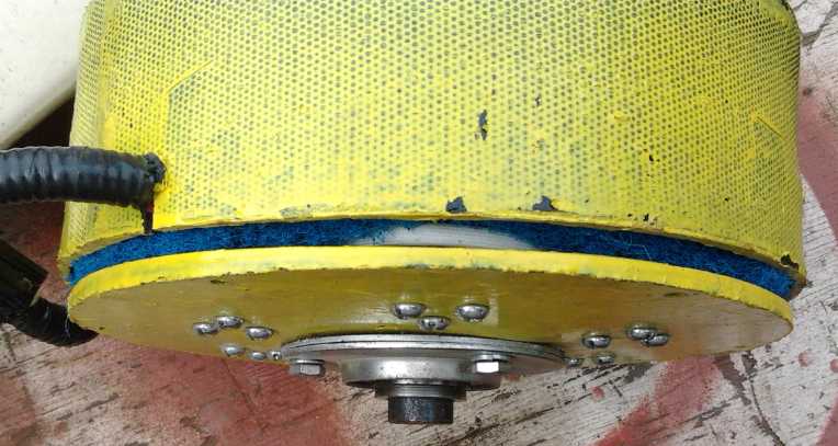
Motor (& Controller?) Troubles - Caik Motor Rebuild
Just as I finished the second set of fixed ratio chain
experiments, there was motor trouble. I found that the insulation had
frayed off the power wires going into the motor and shorted two of
them. Then I found a join that had never been soldered, leaving me to
wonder why it had worked well for several years.
When I put the motor back in the car, it still didn't run
right, losing power in 1/3 of the positions. Finding no more trouble in
the motor, this sounded like blown drivers in the Kelly controller.
To be sure, I decided to at last repair the Electric Caik
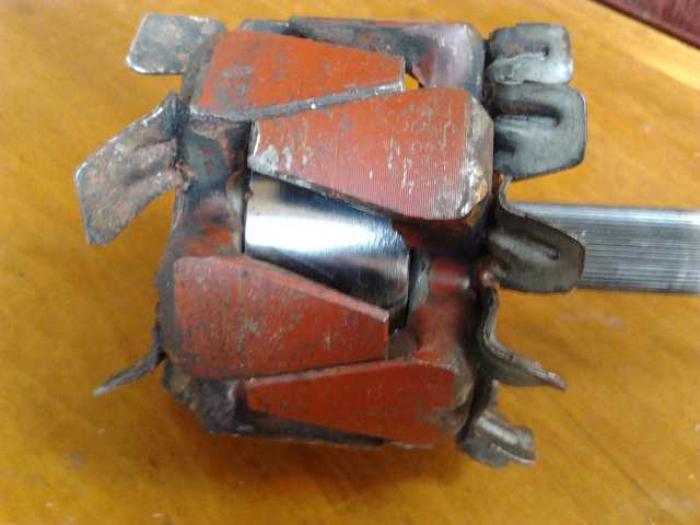
Outboard in order to have another motor to try out with the same
controller. But I also wanted to upgrade the rotor to having an epoxied
strap wrapped around each magnet, which I estimated would make the
motors safe up to at least 3000 RPM instead of 2000. This would be much
better in every way for the outboard. It required milling a slot in the
rotor for each magnet. So the Caik motor rebuild and reassembly became
a project in itself. Other matters came up, and at the end of the month
the motor still needed installing back in the outboard.
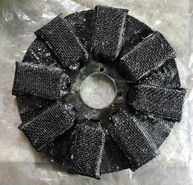 The improved Electric Caik rotor, allowing
higher RPM.s
The improved Electric Caik rotor, allowing
higher RPM.s
(I had to trim the outer corners off the straps - they rubbed on the
outer wall in some places.)
 Bulged stator end of the Caik motor.
Conversion of Car Alternator to Permanent Magnet Alternator
The trouble with car alternators as alternators/generators
for windplants and the like is that they have a 'field coil'
electromagnet in the armature, which is what the brushes power. This
uses power. The more the desired voltage per RPM, the more current has
to go into the field coil to give it more magnetism. In one alternator
I measured 3 amps at 12 volts, or 36 watts, being consumed by this
coil. If your small windplant is making 50 watts in light wind, that
would only leave 14 watts output.
A permanent magnet on the other hand uses no electricity,
so the whole 50 watts is available for output. The disadvantage is that
its voltage (and the current capacity) rises linearly with the RPM.
Typically it won't work at all until the RPM is high enough to give
voltage higher than batteries being charged, and above that it will
put more and more current into the battery regardless of its state of
charge. I decided to put a very powerful ring magnet in in place of the
coil. It
would probably give more volts per RPM than the coil at full strength.
There are other ways to regulate output voltage (once
rectified to DC) for battery charging or other load. A DC to DC
converter with a fairly wide input range will go a long way toward it.
And maybe when it's done, the infinitely variable transmission
(probably under computer control) can maintain some desired output RPM
and hence
output voltage level, regardless of propeller (or other input) speed -
and regardless of varying loads.
 This sounded
like an almost trivial conversion: replace
the toroidal coil with a toroidal permanent magnet. But the devil is in
the details. I wrote last month of the surprising challenges in getting
the alternator apart. Now (September) it had to be modified and put
back together.
This sounded
like an almost trivial conversion: replace
the toroidal coil with a toroidal permanent magnet. But the devil is in
the details. I wrote last month of the surprising challenges in getting
the alternator apart. Now (September) it had to be modified and put
back together.
There was a 'cylinder' of magnetic material that passed
through the coil. That would short out the permanent magnet's
field like a 'keeper'. (At least... I think I have that right. Or I may
be wrong and was wasting my time removing it.) So I
was going to turn away most of the center iron from inside the coil on
the lathe, just leaving a 'button' on each end to mount the magnet on,
but owing to various protrusions there didn't seem to be any way to
attach the pieces to my small lathe. I had to go down to AGO and get
machinist Ralph to do it for me on a very large lathe with a big chuck
that could grab it around the outside without bending the fan blades. I
had hoped this could be a home project for any handyman. It was
certainly not in my thoughts that I'd have to have outside help myself!
Alternator rotor with the electromagnetic coil
replaced by a powerful supermagnet ring
magnet. (The spacings between petals were evened out when pressing the
assembly back
onto the splined shaft. When free they wanted to snap to one side or
the other.)
In Passing
(Miscellaneous topics, editorial comments & opinionated rants)
World Nearly Loses an Inventor
It was probably quite a rare situation. On the 6th or 7th,
I was driving down Quadra Street in Victoria, minding my own business.
It's not a street I often travel on. I stopped at a red traffic light.
There was one vehicle ahead of me. A bus behind changed into the right
lane and came up beside us. The right lane was full of parked cars
except for the space the bus pulled into, the intersection, and a bus
stop not much more than the length of the bus after it. So I hope the
reader will pardon me for assuming the bus must be stopping for
passengers, and I gave it no more thought.
When the light turned green, the car in front of me turned
left, and I started moving. The turning car occupied my attention as we
all started up. The front of my car was just a few feet
behind the bus driver - not much short of being beside him, or should I
say under him. As I accelerated, the bus also accelerated. We both went
through the intersection, both picking up speed and maintaining the
same relative positions. I had expected to almost immediately pull
ahead as the bus slowed, but I couldn't. I couldn't believe he had both
forgotten I was there and also didn't see me. Where would he think I
had gone? What the heck did he think he was doing, with me
almost right beside him? By the time I realized that
he was accelerating at full throttle and had no intention of stopping,
it was manifestly too late to do anything. I could neither pull ahead,
nor drop back the entire length of the bus to get behind him. He
changed lanes right into the space I was occupying, and I had to steer
into the oncoming traffic lane on the left side of the road. Luckily
there was no road divider there and no one was coming. I honked and
finally the bus driver slammed on his brakes and let me get back on the
right side of the road. (Whew, not homicidal after all!) Then, after
almost killing me, he had the nerve to honk at me from behind!
The next traffic light was again red. This time I was the
front car. The bus came up from behind again and pointedly changed into
the right lane again, and pulled way ahead into the intersection to
where I could see a left turn signal flashing in the middle of the bus
- which had again hardly finished changing lanes to the right. He
pulled the same maneuver. This time of course, I waited until he was
well down the street and back in the left lane before I started moving.
Luckily there were no serious consequences except for the
incident haunting my mind, sneaking in unbidden and unwelcome, for
weeks whenever I wasn't concentrating on something else... like when I
tried to sleep or meditate, and on waking up in the morning. And having
to tell myself it was pointless to be paranoid of every other vehicle
on the road when driving - especially buses snapped me instantly to an
extra adrenalin level for a few days. Being unable to telepathically
read the bus
driver's intent, I don't know what I could have done differently. If I
hadn't managed to veer left fast enough or if there had been a center
divider there or oncoming traffic things might have turned out very
badly, and if I had had the wherewithal to honk sooner, or managed to
gain just a few feet to where he would (at last, surely!) have seen me,
the
bus might have run headlong into a row of parked cars.
I kept thinking too of things I might have shouted at the
bus driver at that second stop. Given his honk and his further
aggressive maneuver at that point, I have the impression that because I
didn't respond, he somehow
thought the whole thing was my fault. I'm sorry to have left him with
that delusion. The more I thought about it, the more I think I should
have given him a long return blast from the horn after he honked, or
yelled
"Watch where you're going!" at that next stop. I hope he gave it some
more
considered thought afterward,
or that a passenger told him I had been there all along. Anyway, I
did my best as it happened at the time, as usual not thinking fast
enough and being sure enough of myself in real time to give an
appropriate response. I refrained from shouting anything hurtful.
Finally I decided to write this piece about it in
hopes of maybe helping to clear it out of my mind. Anyway, at least I'm
still
here to think about it.
Some years ago (maybe it was a decade or two), bus drivers
had been complaining that it was hard to get back out into traffic
after stopping for passengers, and a bylaw was made that other vehicles
had to yield to a bus pulling out from a bus stop. Fine. And I've never
had a bus driver expect cars to slam on their brakes and pull out
unreasonably from a stop while they are being passed or are about to
be.
But this bus hadn't stopped or even slowed down. With just two small
vehicles ahead (only one at the next intersection), surely he could
plainly see there were no passengers at the stop before he changed
lanes, and obviously he knew none were getting off. There was,
therefore, no reason for his lane changes -- except to take license
with the bylaw in order to pass a vehicle or two: on the right, through
an intersection, and with nothing but parked cars right ahead if
anything didn't go exactly as planned. When I mentioned the incident to
someone later, they said "Oh yes, they do that." So I guess it wasn't
just this one driver. But if I've ever seen anything like it before, I
don't remember it. Someone else said "The taxis and buses seem to think
they own the road."
If any other vehicle, commercial or private, tried to pull
such an unusual, unexpected and IMHO dangerous maneuver, the police
would be all over them. To do it without even checking his blind spot
for traffic for the whole time was very careless. But nobody's perfect.
I've certainly made my share of errors of judgement and missed seeing
important things while driving over the years. As I say,
doubtless the whole thing was a very rare situation, and possibly I'm
out of line... but I wish the bus drivers would save their stunt
driving
for a movie set.
The fact that my car was metallic dark blue may have been
a contributing factor to the driver not noticing me. I prefer bright
colors, but it was the best, not to say the only, good deal I found
when I
was car shopping. The headlights were on, but they were as much below
the driver as behind him.
Near the end of the month a bus pulled a similar stunt
in a long lineup of traffic, driving down a street
in the "right turn only" lane and then pulling into the through lane in
front of all the other waiting vehicles when the light turned
green - including another bus which had politely got into the lineup
with everyone else.
Fruit Picking Pole Makes Picking High-Up Fruit Safe & Easy
These have long been known, but they're the sort of
product that word doesn't spread about, because no one makes money off
it. There are many variations on the theme, but basically one uses a
long pole with something on the end to pick the fruit with the picker
standing safely on the ground. Mine I made at least 30 years ago with a
12 foot long 1" * 2" board and a large juice can, screwed to one end. A
slit is cut into one side. The user raises the the can on the pole and
gets the can under the fruit. Then he works the stem of the fruit into
the slit and twists. Usually the stem breaks off and the fruit falls
into the
can. For most apples or pears one can pick two, then lower the can end
and release the fruit onto the ground.
I picked about 8 pounds of apples one day from a tree down
by the sea walk, and 9 a couple of days
later. The picking didn't take long - it was the carry home that kept
me from picking more. My fig tree had a few juicy looking figs way up
at the top, too
high even for this pole (and invisible from the ground), but it was
near the house and I could see and just reach some from an upstairs
window.
The can
being horizontal instead of vertical, 3 of 4 figs fell down to the
lawn. My chickens were elsewhere. I had just heard some raccoons go by
below and I hoped they wouldn't return. They
didn't, but by the time I got down to the lawn, a deer was just
munching
one down. It backed off a ways and I found the other two.
Maybe I should move out to the country where things aren't so busy!
(The next time I looked, starlings had found the figs and pecked big
chunks out of the riper ones.)

 12' pole going up to pick figs. - 9 pounds of
otherwise well out of reach apples I bagged.
12' pole going up to pick figs. - 9 pounds of
otherwise well out of reach apples I bagged.
The slit in the side of the can to break off stems is a key feature.
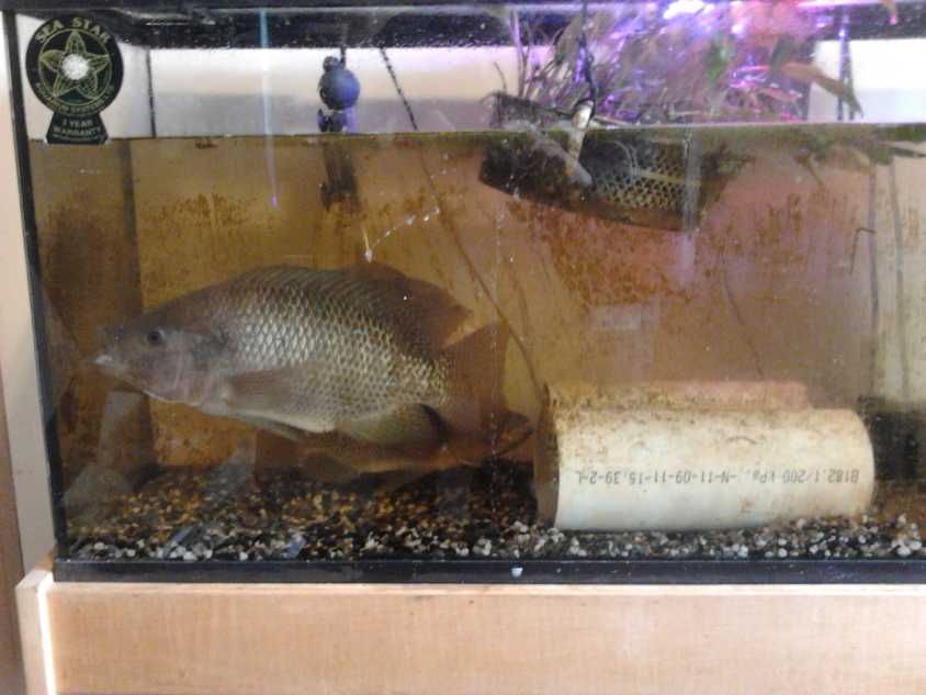
Tilapia Update
Well, I didn't get into aquaponics this summer, but I
still have the 3 tilapia in a 30 gallon aquarium. Every second or third
day I siphon out 2 or 3 gallons of water along with fish poop on the
bottom, and replace it with fresh dechlorinated water. It's
considerable work, but if I don't do it enough the water gets cloudy
and a bacterial bloom starts, and the fish wouldn't last very long.
They just keep getting bigger. The 4" pipes for the smaller males to
hide in are getting to be too small, and the big female can hardly turn
around. But no new brood so far!
The Ultimate Theft: Private Central Banks are Buying Up the Whole
World with Money They Print Out of Thin Air
Well, the title pretty much
says it all. The US Federal reserve, a private corporation as are all
central banks in the western world,
along with the other big banks, collectively own outright over half of
all real
estate (as I understand it, by property values) in the USA. They are
also the
largest landlord. After they [claimed
they] stopped printing 85,000,000,000 $/month, so-called "quantitative
easing", the BOJ (Bank of Japan) went on a printing spree, and then
the ECB (European Central
Bank) started printing up 80,000,000,000 Euros/month. Presently global
printing is said to be at a rate of 160 billion $/month. Next will come
"QE4"
from the "Fed", who are speaking of
printing another 4,000,000,000,000 $. That four trillion will just be
for starters. If the printing stops, the financial and credit system
will immediately crash, which will then crash the economy. This has now
been going on for nearly a decade, multiplying the amount of currency
previously
in existence by many times over. The only thing that's prevented
hyperinflation so far is that the "money velocity" is at historically
low levels, that is, that most of that money isn't really circulating
through the economy - yet.
However, the central banks have been buying up government
bonds ad nauseum, and now governments haven't been taking on more debt
fast enough, so they've
started buying up corporate bonds and company shares - thus also
boosting the bond market and stock market
bubbles so they don't come rapidly crashing down. One result is they
are
also the major players, probably owning large percentages of the total
outstanding stocks in every stock market. And they give loans at almost
zero percent to large corporations, which instead of investing in
growth use the money to buy back their own shares while they lay off
more workers. This again boosts the stock market, and makes the
'earnings per share' stats look better. It's all manipulated to boost
published economic figures - while jobs disappear and more and more of
the whole population is marginalized. The big banks that made far too
many bad loans, for too low rates, highly inflating asset prices in the
process, will all be bankrupt if those inflated prices are ever allowed
to correct to fair value - to where citizens can afford houses et al
again.
Another result is that the companies taking advantage of
these offers are so highly leveraged that when business turns down for
a bit, they become bankrupt. Hanjin shipping (7th largest in the
world?) went out of business in early September leaving 14 billion
dollars worth
of cargo floating abandoned in the world's oceans. Their assets were
frozen and they couldn't even pay the
port fees to land the cargo - goods purchased by the stores for next
Christmas
season. The abandoned crews are running out of food and jumping ship,
leaving them as floating ghost ships. Don't the banks even want to
recover the ships and cargoes, or retain the crews? Maybe that's too
much trouble - just get
more free money instead? The banks have been less than good managers of
the assets they gobble up. Hanjin is only one of many companies now
deeply leveraged which will probably go belly up in the near future.
(This also demonstrates how the entire distribution system will freeze
up when
credit dries up.)
So the banking system keeps itself in business by buying
up everything so prices don't drop, with payments to politicians to
keep governments in collusion and have special laws written for them,
while the real economy sinks under
the burdens of inflating prices with (on average) dropping incomes, and
the
artificially created scarcity.
The Swiss and Norwegian central banks recently (~Sept.8)
printed a billion dollars worth of currency and used the money to buy
up shares in mining companies - a clandestine means of buying gold and
silver without crashing the COMEX and LBMA and driving precious metal
prices way up - which might by itself initiate the economic implosion.
It's all theft on the largest scale. Those who print the
money are becoming the owners of every tangible asset on the planet,
while the whole population is being gradually stripped of whatever they
have.
Most people, using their increasingly hard
earned money to buy things they need, are now in direct competition
with those who freely print the money, whenever they try to buy any
form of real property. Are they not being cheated? Are the 99% not
getting shafted? On the 22nd it was reported that almost 100,000 people
in New York had applied for one-time emergency assistance to pay their
rent. All over the USA, people are living in campers, vans or even
cars, or are entirely homeless. Where are the core values of social
sustainability -
Quality of Life, Growth Conditions and Equality? They are going down
the drain in a sea of debt owed to those few who so freely create the
money. Is this not the world's largest bubble in all of history, with
virtually everyone
heavily in debt (owed to who?), which must soon pop?
An aside: Growth of societies that suddenly collapse with huge
losses of population has been the history of this planet so far. They
are usually preceded by unsustainable population expansion. You've
heard of the fall of Rome. But did you
know it was preceded by such onerous taxation over the decades that
many peasants abandoned or lost their land and became slaves to large
villas,
or went to live with the barbarians? With such inequality there were
repeated bouts of plague, and no thriving rural population
in the Italian countryside to draw from when Rome needed soldiers to
defend the city as there had been in the times of the republic. And
you've heard about the Black Plague that killed over 1/2 the population
of Europe from around 1350 to 1450. But have you heard about the
banking collapse of the 1340s that cut off all credit, impoverished
Europe and so paved the plague's way? And you've heard about the Irish
potato famine, but did you know it was the introduction of the potato
to Europe from the new world that had first brought about a rapid,
unsustainable growth of the Irish population?
The juggernaut forces hurtling us towards the economic
cliff are
almost global, or at least they pervade the entire western
financio-economic-political system, as David Quintieri so clearly
illustrates (see next item). Climate disasters, huge die-offs of life
(mostly caused by geoengineering?) and (for whatever reason) a great
rise in occurrence of physical catastrophes everywhere threaten food
supplies at their source. Huge population bubbles in eastern Asia and
Africa, along with antibiotic immune disease organisms, are setting
things up for a sweeping plague or plagues. The crash or even a series
of crashes can hardly
be prevented or too much
longer delayed at this point.
We can however, educate ourselves to understand what is
happening and why, and perhaps begin to formulate and discuss solutions
based on the core values so that this will be the last time it happens
on this planet. After some real, population crashing disasters both
environmental and socioeconomic, now complacent people who survive will
develop enquiring minds, ready
and receptive to new solutions: environmentally sustainable
technologies and socially sustainable institutions. eager for them.
Will the new solutions be available for them, or must we enter a new
dark age? It's always up to individuals, and everyone can play some
large, medium or seemingly small part in making the world better
instead of worse -
improving the quality of life, growth potentials and equality among all.
The Web of Conflicts of Interest between the USA Government and
"Corporatocracy"
One sees that the USA government for decades now has
always put corporate interests ahead of the public interest. Perhaps
most visibly Washington defames peaceful leaders to invent enemies and
puts
war ahead of peace on behalf of the arms merchants. They are nearly
always at war.
David Quintieri has done a youtube video that clearly
shows why this is inevitable: in a series of Venn diagrams he gives
names of an amazing list of people who occupy both a high, influential
post in government (eg, congressman, senator, senior civil
service, committee head, regulatory agency head...) and a high,
influential post
in a huge, corrupt corporation (eg, CEO, CFO, board member, head
lawyer...). There
are separate diagrams for Big Banking, Monsanto, Big Pharma, General
Electric, big military industrial corporations, and some others. You
will see some perhaps familiar names.
These rampant conflicts of interest show how the whole lot
of them are in it for selfish gain and power, and why they will never
as a group do anything to try to fix the problems. (One always holds
out hope for individuals, but any there may be are bucking a flood tide
pouring over and bursting through all the levys.)
Sometimes they are even conflicted within themselves, such
as when the Pentagon objects to the Navy developing a new weapon
(magnetic rail guns) instead of buying existing munitions from the
ensconced arms merchants, and when CIA (cocaine importing agency)
backed rebels in Syria fight with Pentagon backed rebels.
Title: Give
Me 7 Minutes and I'll Prove Google and Government are One Entity (And
More)
By: David Quintieri
Date: August 15th 2016.
https://www.youtube.com/watch?v=IVzXdZRVbII
As I indicate, this little viewed video goes far beyond
Google and constitutes the most convincing exposé of the
collusion and connections between government and parasitic huge
corporations I've ever seen. I think it should be given the widest
possible distribution!
Dr. Paul Craig Roberts (co-father of "Reaganomics") also
speaks of "the deep state" and why it won't matter much who is elected
president unless he can immediately replace a whole host of officials.
"We faced this with the Reagan administration. It was a real
knock-down, drag-out fight to get anybody on the administration who was
on the president's side." says Roberts. "When he appointed me, they put
a hold on my appointment. They didn't want anybody there who was going
to do what the president wanted." He says a study has shown the public
today has zero influence over decisions made by government. It all
makes perfect sense once you've watched Quintieri's video.
"When plunder becomes a way of life for a group of men in a society,
they create for themselves over the course of time a legal system that
authorizes it and a moral code that glorifies it." --
Frédérick Bastiat, 1848
Voting Reform Committee Meeting
I have previously mentioned the ideas I've written about
in http://www.HandsOnDemocracy.org .
Now the Canadian government, having promised in the last
election, has set up a 'voting reform committee', and it - about a
dozen members of parliament (MPs) - had a public meeting on Tuesday
September 27th in Victoria, which I attended along with 100 other
people. There have been similar meetings in other Canadian cities.
Someone from the 2003 "BC Citizens Committee on Electoral
Reform" was featured and the MPs asked him a lot of questions, which he
answered very well and articulately. Perhaps all their work was not in
vain after all! I hope the sessions in other cities went half as well
as the one here in Victoria.
Members of the public had 2 minutes to speak. I mentioned
something about "common ideals, the core values of quality of life,
opportunities to grow into one's potential, and equality", and the
HandsOnDemocracy.org URL, and said that the subjects covered at the
meeting were a subset of a larger puzzle. I gave out a few cards I
printed with the URL, including to a few of the MPs.
I don't think there has ever been anything like this
before, and I'm glad I went. It's along the lines of the national
government becoming "a learning organization", able to evolve from the
petrified forms of yester-year toward more advanced procedures, with a
"design team" of a dozen members charged with fact finding, public
consultation and formulation of whatever they formulate. It's a very
promising development, and perhaps historic! I should have stayed to
the end, but it was past suppertime and I left a while after I spoke,
with another 50 people (nearly 2 hours) to go.
Of course not all ideas from everyone agreed entirely with
mine, or with each other, but assuming they are actually listening (it
seemed they were) - and if the government elected by the present system
is actually willing to change it - there will be changes made to the
way Canada votes, and they will be improvements. I was pleased to hear
several people speak who recognized how the present single ballot "X"
voting system has polarized politics, and some other sentiments and
ideas on voting and elections similar to some on my web page.
Honey Bee Ecological Catastrophe
In fear of mosquitos with zika virus (an obscure African
virus which is (or until recently was) available for sale in vials on a
Rockefeller website for about 600$), South Carolina sprayed a
nicotinoid pesticide
(one that's banned in Europe) to kill them. They got an environmental
disaster as it killed every honey bee in at least one county. Entrances
to hives everywhere were littered with dead bees, a symptom of acute
pesticide poisoning. Doubtless other species of bees were also killed
off. We may not hear more on this story, but the area will surely be
impoverished in life next spring and perhaps for several or even many
years, as honey bees are the most important of all plant pollinator
species, and animal life depends on plant life. Depending what's grown
there, the area extent of the die-off, and how fast bees move in from
elsewhere (assuming the pesticide dissipates over the winter), they may
get no crops next summer.
(Weeks later:) The spraying continues in the region. It's just one more
in a
long list of ecological
disasters, which are mostly man made. On October first, Full
Spectrum Survival youtube channel's Daily News Update
reported that a number of USA bee species have just been placed on the
endangered species list.
Improve Health and Increase Life Expectancy: Metformin
Life expectancy has been on the rise for quite a while.
When one looks back at the earlier music composers from the 1400s to
the 1700s, one sees from their birth and death dates that many (eg
Mozart) died in
their 30s. In the last couple of centuries people often made it to 80
or 90 if nothing struck them down. Edgar Casey was occasionally asked
about "How long should I expect to live?", and the answer was usually
"around 120 years" - for one person, "140". I also hear that on very
advanced worlds the people can live for hundreds of Earth years.
Why is it virtually no one makes it to 120 or 140 or
beyond? What are we missing, or how are we harming ourselves, that we
never get there? We don't know. But there is a drug that holds
considerable promise for changing that. Metformin was created in 1922,
and started to be used as a type 2 diabetes medicine. Once it had that
label, any idea of using it for other purposes was overlooked or
forgotten. But in recent decades it's been discovered that it has a
whole host of health giving properties. It's anti-cancer, anti-obesity,
anti-diabetes, anti-Parkinsons, anti-dementia/alzheimers, probably some
other things I don't remember -- and anti-aging. A real miracle drug!
It has mild side effects, which may include: gas, upset
stomach, 'loose stool' or even diarrhea. These usually subside if it's
being taken regularly. (I can get those from eating chilli, which is
non-prescription.)
It has received glowing reports from all the more recent
research as a means for greatly extending one's potential life span.
The Articles mention the same "120 years old" figure, or "live 40 years
longer". And not only will it help one live longer, but those years
will be healthier.
I am somewhat dubious of the "40 years more" claim. When
people find out something new, they usually seem to overstate the case
by
a good margin. Still, if it's 5 or 10 extra years, and if those
are healthier years, is it not worth taking? But if "40 years" isn't
here yet,
perhaps with further research still better things will be created.
The other technique of course is for people to consciously
select partners and put an emphasis on selective breeding to gradually
create better and longer lived races of people with fewer and fewer
genetic defects. We know more about genetics now, but even in ancient
times people selectively bred plants and animals with good results. And
once steps are being taken to limit the global population to prevent
yet another
repeat of the "grow until collapse" scenario now playing out, it will
be much easier to say, "you guys are great, go ahead and have 4 kids",
or "could you please limit the size of your family, or not have one, in
the community interest?" Such measures would of course have to be by
general and genuine social agreement, not imposed from "the top" down.
Now I have seriously digressed! Working from both angles, I'm sure such
age figures will someday be attained and then surpassed by most of the
population, who will then view our shorter lives as a part of history,
the "bad old days".
My sister in law has diabetes and takes four 500mg tablets
of Metformin a day - 2000mg. I believe it's what got her (and another
diabetic I know who takes 1500mg/day) off the insulin needle. Her
doctor has said "They should
put it in the drinking water!", which he probably wouldn't actually
recommend if pressed, but it's a powerful endorsement. No doubt he
takes it himself.
Again proponents are likely to think that if some is
good, more is better, overstate the case and suggest taking more than
is really helpful. (One doctor thinks everyone over 40 should take 2mg
of melatonin per night as "the body no longer produces enough." The
pills come in 3mg and 10mg sizes. I find at age 61 that 1mg really
helps me stay asleep at night.)
Perhaps 250mg of metaformin a day would be a good dose for
healthy
people. 500mg would surely be the top. Side effects would doubtless be
minimal if not unnoticeable at low doses. And maybe it would be good
for people over 50 or so -- or younger if there are any signs of
troubles it can prevent. And potentially it's cheap - "16¢ a
pill". But having been prescribed for diabetes, it's become a
prescription medication and you can't buy it unless your doctor says
so, and apparently unless you have diabetes most doctors won't
prescribe it. And even if you get a prescription, it will cost a lot
more than it would if it were freely stocked in store shelves.
Considering all its healthful properties for so many
things and its few and mild side effects, this is a pointless and sorry
state of affairs. It's not
a dangerous substance that needs to be carefully administered, and it's
not an antibiotic whose use would be controlled to prevent pathogens
from becoming immune to it. It should
be freely available over the counter to anyone who
wants it. The very fact that it is prescription doubtless prevents
people from hearing more about it. Tylenol overdose
causes 50000 deaths a
year in the USA and that's considered acceptable. Metformin will
doubtless be hardly a blip on the radar screen, if that, by comparison.
It would become matter of course for the doctor and pharmacist to
mention it if something is prescribed that doesn't mix well with
Metformin.
If Metformin is anti-cancer et al and extends health and
life, there's
a good argument to be made that keeping it "prescription only" is in
effect
killing millions upon millions of people, making them less healthy and
ending their lives needlessly early.
Nepot & Sons
Far and away the best example of nepotism is "royalty".
Take a nation's top political post (head of state), get your entire
family in on it from grandma to the kids, and pass it on to your next
of kin in perpetuity.
An astronaut? What's that? Man: "What do you want to be when you grow
up, son?" Kid: "I want to be
a juggernaut!"
Newsletters Index/Highlights: http://www.TurquoiseEnergy.com/news/index.html
Construction Manuals and information:
- Electric Hubcap Family Motors - Turquoise Motor Controllers
- Preliminary Ni-Mn, Ni-Ni Battery Making book
Products Catalog
(Will accept BITCOIN digital currency)
...all at: http://www.TurquoiseEnergy.com/
(orders: e-mail craig@saers.com)
Electric Hubcap Motor Systems - Electric Transport
Electric
Hubcap motor, Chevy Sprint & Infinitely Variable Transmission
...& Electric Caik motor
A thought occurred to me on the 4th. If the left end of
the differential is speeded up instead of slowed down, in addition to
reversing the direction the torque
required of the variable pulley drive should drop. So, decreasing
torque from it as the car heads towards highway speeds. The difference
between say 3 to 1 and 9 to 1 is substantial. However, that's backwards
- it doesn't
help
much for getting it going. with 3x reduction on the fixed side, the
neutral point is 1.5x either way. The difference between 1.3 to 1 and
1.7 to 1 for a "low gear" isn't a lot. Either way it's a lot of torque.
Just a thought.
Sprint Prototype with a Third Shaft
In August a fixed ratio V-belt drive experiment failed to
perform in
place of the planned variable drive because the belt just slipped under
load. Owing to the high differential ratios, it didn't need to slip
much to prevent the car from moving. (I should have tried sanding the
smooth enamel
painted pulleys to roughen them up to grip the belt better.) I
started to think it would be necessary to make something like a
production transmission unit, placed before a final drive reduction, in
order to lower the torque loads to the variable section, before the
Sprint could be made to run the way I intended.
Then I conceived that if a third, intermediate, shaft was
added, the unit could have a lighter variable section running at higher
speed to that
shaft, then a chain drive reduction to the differential gear. This
would lower the torque requirements and also add flexibility, because
this new shaft could be placed so that any reasonable length belt in
the variable
section could be the right length.
On the 3rd I made another shopping trip to Princess Auto.
I bought the asymmetric "CVT" belt, a 36 tooth sprocket gear and hub
for the end of the differential, a 16 tooth one to connect the 3rd
shaft to that, and a 20 tooth sprocket and hub for an experiment. These
were all for #40
chain which I have some of, and I got a couple of links and half links
for it to close the ends.
I also looked at, but didn't buy, one of the complete
"CVT" units. Both ends were unsuitable. The input pulley was operated
by centrifugal force, which made
it operate backward to the desired configuration. The output pulley
had a centrifugal clutch, which only went to a small, lightweight chain
sprocket, maybe #30 chain, 12 teeth. There
was no way to connect it straight to a shaft. And the input pulley was
smaller than the output, which (see below) was also backward. But if
nothing else, I learned that the asymmetric drive pulley angles are
18° and
2.5° - not quite straight. 2.5° makes sense as the belt might
rub
on the outside of the pulley if it was absolutely right angle.
The 16 tooth to 36 tooth chain drive gives a 2.25 to 1
reduction, so the "CVT" will run that much faster with that much less
torque load than if it went straight to the differential. (still a
pretty hefty load!) So the lowest desired reduction would be
1.333 instead of 3, and the idle point .667 instead of 1.5. In other
words, the speed is actually increased for 'low gears' and the output
pulley need be only a little larger than the input one for the 'high
gears'.
Single Variable Pulley with Third Shaft - or Controlled Idler Arm
Usually with a "CVT" unit, if one pulley expands the other
must contract in order that the belt length remain correct. And this
also allows a considerable variation in reduction ratios, over 3 to 1
or maybe 4. On the 18th
I conceived that with only needing a 2 to 1 change
in ratios to get a huge difference in final drive
ratios, only one variable pulley would be needed. The other end
(either end, as convenient) could have a fixed size
pulley. But then of course, the distance between pulleys would vary.
But in
fact, that could be a big advantage: changing the distance between the
two pulleys, one
being a spring loaded variable width pulley, could be the means to vary
the 'gear' ratio.
The third shaft could
pivot on an arm with a pivot bearing at the differential. No matter
where it was pivoted to, the chain length between the third shaft (now
the control shaft) and the differential would stay the same. Thus the
chain
drive would be unaffected by the pivoting. The third shaft could
move toward and away from the motor shaft in a small arc, forcing the
spring loaded variable pulley to expand or allowing it to contract. No
connection to a variable pulley
to move it in and out would be required - moving the arm would do it.
That of course would be accomplished via the cable to the shift lever
in the car. And maybe later under completely automatic control.
So, it won't need a throw-out bearing and "clutch forks"
to move one side of a pulley along the shaft after all! It's still not
going to be trivial to put together either the prototype or a
"production" unit, but each new idea so far seems to be making it
simpler.
The spring loaded variable pulley I got
goes from about 2.5" to 4.5" effective belt diameter, a variation of
1.8 to 1. Since the motor has its own reverse, that should be good
enough, with the right size fixed pulley. The symmetric belts seem to
fit well right at the outside of the cast steel regular V-belt pulleys,
tho cast aluminum pulleys seem too narrow. If
anything,
they seem less inclined to slip than a regular V-belt.
Next Experiments: Fixed Ratio Chains
I thought that the fixed differential drive ratio
experiment should be repeated, with a chain drive instead of the
V-belt. The chain drive couldn't slip. (unless a sprocket gear slipped
on the shaft - which did happen with the belt drive. It's a lot of
torque!) So it should move the car this time, unless some other problem
introduced itself.
For this I got the 20 tooth sprocket, providing 1.8 to 1
reduction to the 36 tooth one, which would be installed on the
differential left end both for this and for the final configuration.
Since it'll be going direct to the differential for the experiment (no
3rd shaft yet), that's turning somewhat slower than the 1.5 to 1 idle
point. A
24 tooth sprocket would have given the idle point ratio, where
the car wheel wouldn't move at all. I had wanted a 21 or 22 tooth to be
fairly close to that but not on it, but there were no sprockets
available between
20 and 24. There was a 26 tooth sprocket that was closer, on the other
side of the idle point. (Who cares which direction the motor must run?)
Why I didn't buy that one instead? I don't remember. If the 20 tooth
was
geared too high for getting moving I'd go back for the 26.
 I bored out
the 36 tooth's hub to 30mm (from 1-1/8") for
the shaft that
fit into the splined differential's socket, then welded the hubs to the
sprockets. I just tacked on the 20 tooth one so I can grind it off
later and re-use the hub if I want a different size. In spite of buying
one of them new-fangled auto-darkening welding helmets, my welds with
the
new MIG welder look just as professional as those done when I first
started with the big stick welder a decade ago. Not that I get much
practice.
I bored out
the 36 tooth's hub to 30mm (from 1-1/8") for
the shaft that
fit into the splined differential's socket, then welded the hubs to the
sprockets. I just tacked on the 20 tooth one so I can grind it off
later and re-use the hub if I want a different size. In spite of buying
one of them new-fangled auto-darkening welding helmets, my welds with
the
new MIG welder look just as professional as those done when I first
started with the big stick welder a decade ago. Not that I get much
practice.
4th: Starting before breakfast, I fitted them on and
turned the motor by hand. The car seemed to want to move but
didn't. I drew some felt pen marks on the shafts. Sure enough, tightly
as I'd done up the set screws, the sprocket at the differential was
slipping. I took everything apart. I tried to mill a key slot in the
lower shaft, but it just dulled the 1/4" HSS end mill, badly. And
somehow
that turned out to be the only 1/4" mill I had. I gouged a rough keyway
into the shaft with the angle grinder and ground a key down to fit it.
Then I resharpened the mill (not very well) and did a keyway in the
upper shaft before the upper sprocket had a chance to give similar
trouble. I made a key for the slot, and then spent some more time
putting everything back together and into adjustment again. Sometime in
that I had breakfast after 2PM.
I powered up the motor controller and got in the car. It
didn't seem to want to move backward, but it moved forward a bit, then
when I flipped it to 'back' again, I had rocked it out of its little
pothole and it went - for a couple of feet. Then the chain started
skipping.
A bolt in a slot, which is done up with the chain tight
(or now, with one tight and one almost tight) had slipped. Tight as I
did it up, when the going got tough it kept slipping and slacking off
the chains, which then skipped. I already knew it needed some way to
positively lock it into position. I did it up one last time, pressed on
the pedal gingerly and drove a few feet into the shed to park. The day
was pretty much gone and I had other things to do.
5th: I found where I could put in a thin
wedge of steel and put a nut
on a bolt to hold it in place, to hold the chain tension adjustment
from slipping. It was a bit makeshift, but the simplest solution and it
worked. When
the third shaft is added things might need changing anyway. I backed up
the car a few feet and suddenly the motor was spinning freely. Sigh!
The thin washer with a slot in one side to slip it in, to hold the
shaft in the differential, had bent and it had loosened off of the
splines that lock them together. I had been worried about that weak
spot. I found a fatter washer and cut a slot in it, but I had to grind
a little off the head of the bolt and then mill down the path of the
head along the slot in order to force it into the thin space.
Tightening the bolt seemed to pull the shaft farther into the
differential socket instead of bending the washer, so it was better
than the
first one. I'm still worried the bolt will unscrew itself while driving.
Then I drove the car back and forth a bit. Again it didn't
start moving readily, and the slowly turning motor got hot pretty fast.
It probably would have been a pretty good "second gear" ratio from say
7 to 30 Km/H. When I went between forward and reverse there was a lot
of slack after the motor started turning before the car jerked into
action. The chains were both pretty tight, but there's a lot of play in
the differential gear. The play is magnified by the reduction ratio.
Recalling that 24 teeth would have been "idle", using the
20 tooth gear had not made for a really low final differential
reduction ratio, 9 to 1, and the car didn't start moving readily if it
was uphill. A larger motor should have had no trouble even on hills
with
this ratio, but it's part of the plan to run a car with a smaller
motor, and with a variable drive ratio one should be able to get close
to the 'idle' ratio and run at high reductions of 15, 30 or even 50 to
1. (Obviously the final drive ratio obtained can be calculated by some
simple pretty formula. So far my mind has rebelled at attempting to
figure out what that formula is.)
Nevertheless, I found out later when I tried a 26 tooth
sprocket that things were jamming up when the torque needed got higher,
ie, when going uphill. Without that unsuspected problem, the 9 to 1
would
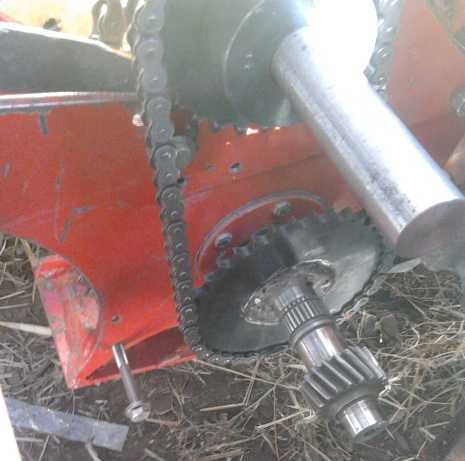
surely have worked better. On to that...
The 26 tooth gear would be 1.38 to 1 against the 36, not a
big speed change from 1.8 in itself, but it provided about -16 to 1
final ratio from motor to
wheels. That should have been nearly double the start-up torque - also
reversal of motor
versus car direction. Since the motor runs either direction fine,
direction isn't important except it would be nice considering wear for
the differential gear to slow down as the vehicle speeds up, rather
than speeding up. OTOH, in a production model, the 'differential' would
be one
that was made for the job, to spin freely in air without issues, so
that should be no concern except for this prototype. A 21 tooth
sprocket - the size I would have got if they'd had one - should have
been about 13 to 1. At this point I wanted to try the 26 tooth
sprocket, but it was labour day and the store would have been closed,
so that was it for the day.
 The next day I bought the 26 tooth sprocket and a hub. But someone had
put a 7/8" bore hub in the 1" bore bin, and I neglected to check when I
bought it. So I had to go back the next morning (7th) and get the right
hub. I welded the sprocket to the hub first thing, because it looked
like it might rain and I couldn't weld if it was damp out. Then I got
out another piece of chain and made one to fit.
The next day I bought the 26 tooth sprocket and a hub. But someone had
put a 7/8" bore hub in the 1" bore bin, and I neglected to check when I
bought it. So I had to go back the next morning (7th) and get the right
hub. I welded the sprocket to the hub first thing, because it looked
like it might rain and I couldn't weld if it was damp out. Then I got
out another piece of chain and made one to fit.
Basically everything checked out according to theory:
forward became reverse, and the motor turned about 16 times for one
turn of the wheel - a very high reduction ratio. Or it would have been
if it
could go a whole turn of the wheel. One would expect the car would move
readily, uphill and down, with this high reduction ratio. But it didn't
go far before things seized up. Somewhere, when the torque got too
high, something was jamming. With this sprocket, one chain is highly
taut at
the front and loose at the back, while the other is opposite. Finally I
had to slack off the chains to get the seized-up differential to move
and the car to roll again, at all, in either direction. It was after
this that I realized that high friction was doubtless the same problem
the 20 tooth ratio had had with going uphill. It wasn't that 9 to 1 was
necessarily
too small a reduction ratio for small hills. This 26 tooth one, giving
18 to 1, actually worked much worse!
I suppose the tension on the chains, and hence the
propensity to develop high friction, is multiplied by the reduction
ratio? That doesn't sound right... Could there be some hidden, inherent
problem in the whole idea of this torque converter? The cause needed to
be identified
before anything else.
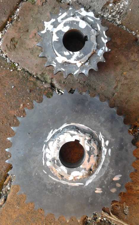
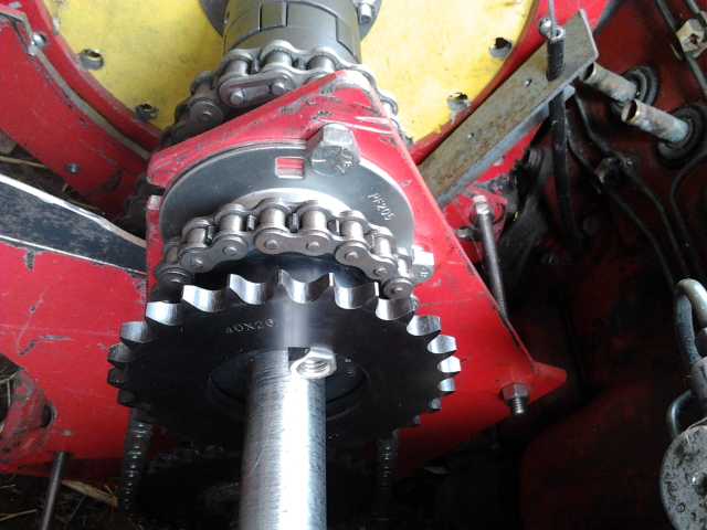 The 26 pin and 20 pin sprocket sizes compared.
This illustrates the effective amount a variable pulley would have to
change to go between
"reverse" and "2nd gear" ranges. And highway speeds would be somewhat
smaller yet.
With a motor that reverses electrically, it wouldn't need to expand
much beyond the smaller size.
I would have put the 20 tooth sprocket back in and checked
for friction - turning the motor by hand reveals it just as well as
running it - but it started to rain. The next morning (8th, sunshine!)
I went out and looked again. This time I stood inside the hood with one
foot on the end of the shaft sticking out of the differential, and
started turning the motor by hand. And this time it didn't jam up until
it hit quite a steep uphill point, when the chain no doubt had more
tension on it than my weight. I thought that was it! The differential
gear could handle heavy symmetrical loads, but with only one bearing on
one end of the shaft, the left end couldn't handle sideways pulling
loads like a chain or belt. And with the center gears running around
the middle through opposite points, it may have worked (eg) at 0
degrees and 180, but not at 90 and 270°. That might explain some of
the effects, like with the 20 tooth starting up okay and then stalling
- it wasn't actually hitting hills, it was reaching a bad point of
rotation. I was glad I had left the long end on the shaft so that I was
able to perform this test. Otherwise I might have cast around looking
for other causes for some time. But the next day I did find another
cause.
Second Fixed Ratio Chain Tests
At first I despaired of finding some way to mount a
bearing to take all the force on the outside of the shaft. It would at
least involve taking everything apart and welding something new onto
the case. Maybe I should be thinking instead of a production prototype
after all? Then I thought that I could simply make a bar with a bearing
at each end and put it between the two shafts. That should exactly
counter the force of the chain between the two, and luckily I had made
the top shaft extra long, too. That should do for experimental
purposes,
anyway.
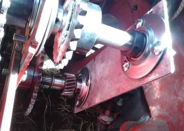 On the 9th I
made a 12" x 4" x .25" aluminum "bar" piece
to hold two needle bearings (luckily I had them) at 8-7/16" apart, the
approximate distance between shaft centers with the lower one between
flopped down and pulled up, and with the main chain relatively tight
(fixing the position of the upper shaft). I cut out the bearing holes
with a jigsaw. Filing them out until they fit took quite a while,
starting with the cuts a little undersize in many places. If the holes
were too big they would fall through and my mounting scheme wouldn't
work.
On the 9th I
made a 12" x 4" x .25" aluminum "bar" piece
to hold two needle bearings (luckily I had them) at 8-7/16" apart, the
approximate distance between shaft centers with the lower one between
flopped down and pulled up, and with the main chain relatively tight
(fixing the position of the upper shaft). I cut out the bearing holes
with a jigsaw. Filing them out until they fit took quite a while,
starting with the cuts a little undersize in many places. If the holes
were too big they would fall through and my mounting scheme wouldn't
work.
The needle bearings, each with a stamped-out bearing
holder pressing them into their holes in the aluminum piece, can lock
to the shafts with a setscrew - vital since there were no attachment
points except the two shafts. I wasn't sure 8-3/8" wouldn't be better,
but it could be adjusted slightly closer if desired by sliding the top
bearing along the shaft before doing it up, with the bar angled a bit
between the shafts instead of straight on. I thought this arrangement
would be adequate to prevent the differential gear from jamming.
The result was disappointing. It seemed to jam almost as
badly. I finally realized that the two shafts didn't quite line up. The
chain fit a little differently than with the 20 tooth and pulled the
top shaft down more, twisting it relative to the lower one. And then I
realized it was the chains, just slightly out of line, that jammed at
high torque as each new link, under high tension, was being pulled onto
the driving shaft's leading sprocket. This was unexpected to me. Of
course, although it had been quite a while since I had made the
original chain drive, I had never tried designing something with a
chain drive before. Working on bicycles as a kid... the bikes were
already made, lined up! And the torque was much lower and the chains
longer,
reducing the effects of the misalignments of 10 speed gears. I hadn't
realized that the sprockets have to be in absolutely precision
alignment, at least if there's a heavy pull.
This wasn't a problem (AFAIK) with the original chain.
(...or was it part of the reason the earlier converters only seemed to
work up to a certain torque level? Hmm!) But the new one, being badly
out of line with the 26 tooth sprocket, worked very badly. (Maybe the
chain needed another 1/2 link?)
 I put the 20
tooth sprocket
and chain back on, but it didn't seem up
to pulling the car uphill. In fact, I found I couldn't push it up
either, nor crank it up with the torque wrench on the wheel, which
pinned out at 150 foot-pounds or more. That was a first! It had never
needed that much torque at the wheels to move it before. That upped my
previous estimate that 150 foot-pounds would be enough to get the car
moving under any normal circumstances. It needs to have 200 available.
Of
course it will get it if the variable converter is working right.
I put the 20
tooth sprocket
and chain back on, but it didn't seem up
to pulling the car uphill. In fact, I found I couldn't push it up
either, nor crank it up with the torque wrench on the wheel, which
pinned out at 150 foot-pounds or more. That was a first! It had never
needed that much torque at the wheels to move it before. That upped my
previous estimate that 150 foot-pounds would be enough to get the car
moving under any normal circumstances. It needs to have 200 available.
Of
course it will get it if the variable converter is working right.
I had rolled - driven - the car back farther than usual.
The back wheels were definitely going upslope. I decided a front one
must have fallen into a pit the chickens had dug, and in fact I had to
jack one up and put a board under it before I could finally rock the
car ahead. (I'm not sure about the chicken theory, but all 4 wheels had
to get out of their ruts to move it.)
Well, misaligned chains and shafts were a big problem in
the prototype. Of course in a production unit, everything would be
perfectly aligned by design, not thrown together. One expects perfectly
aligned chains and sprockets wouldn't jam... would they? Was it perhaps
time
to give up on the persnickety prototype and start designing a
production one after all? Let's see... if I made flat plate sides, I
could have them cut from aluminum or steel at a CNC waterjet place.
That would
avoid making cast pot metal cases and still effect precision placement
of mounting points to avoid potential misalignments.
Chain Tests: Conclusions
The experimental tests were a success, and proved to be
valuable if not essential to the general progress. It shows the value
of doing such an
experiment even tho the results would seem to be a foregone
conclusion.
As expected the reduction ratios between motor and wheels
were demonstrated to be based on the difference in ratios between the
two drives to the two components of the differential gear, and as that
ratio approached 2 to 1 (or in this case 3 to 1.5), very high overall
reduction ratios, of 9 and -16 to one, were attained from a single
stage of reduction gearing. Relative to motor direction, the car moved
in one direction below [3 to] 1.5 and the other direction above 1.5. It
was pretty obvious that it would have to, from a description of the
operation or a drawing, but here was proof that there were no flaws
in the logic.
They also demonstrated once again that the forces to move
a car are very substantial (in case we didn't already know that) and
that unless everything is robustly and properly built, something will
slip, give out or jam before it obliges by moving. That the poorly
aligned
chains, and perhaps the unsupported left end of the differential, were
jamming - the unsuspected cause of frustrating problems - was
disclosed. If I had built the variable belt drive prototype without
doing these experiments, the belt would surely have slipped because of
a jamming chain, and
without understanding the real reason, the whole project might have
been once more set aside, perhaps indefinitely, in frustration.
And not all the effort was single-use: The 36 tooth
sprocket on the differential left end was to be the finished component.
Motor Trouble & Electric Caik Motor Upgrade
After I got the car out of the potholes I ran it back and
forth a couple of times, noting that it went okay except a couple of
times it either jammed up or couldn't make an uphill bit - I'm not sure
which, as they would both happen at similar higher torque points. Then,
at the
end of the day and having done all the tests, the motor ceased to run.
In the evening I checked out the repeatedly blinking codes on the red
light in the controller: [... .. ... . ...
.. ... .] Um, "reset"
and "frequent reset". "High current or momentarily low battery
voltage." Could the batteries be low already? I charged them overnight
and in the morning (10th) I checked the connections and put a meter on
the power at the controller. Everything seemed fine except the blinking
light on the controller. Then I wiggled the wires at the motor. The
controller then stayed green, but the motor wouldn't turn. Okay, that
would indicate: One of the power wires had come loose, and it was
shorting to another. When I wiggled the wires, the short came
disconnected, but the motor only got power in two positions out of six,
when just the other two wires were powered.
When I opened the stator of the motor (12th), I found
frayed insulation just where the wires entered. There was nothing
disconnected. That seemed very bad, because when I had un-shorted the
wires in the car, presumably it should have run. The fact that it
didn't and yet had no bad connections now seemed to point to trouble in
the
motor controller, no doubt caused by the short. It was some time before
I ventured to continue working on it. The wires had cloth insulation
(old salvaged wire from the days before plastic (?) coated wires.) and
I had put motor sleeving over them. All had worn through with vibration
- physical and probably electromagnetic. My opinion of wire sleeving as
insulation went down drastically. Apparently I needed to improve
the arrangements! The first thing that occurred to me was that most
motors have a wiring box on the outside. The second thing was
immobilization, which would presumably be with epoxy for this motor.
The third was that since my
motors have plastic bodies, I could easily route the 3 power wires
through 3 nearby but separate holes, where none could touch each other.
I picked that solution.
But what about the fact that it hadn't run when un-shorted? It seemed
worth going through it and checking for any bad connections. But where
might a bad connection be? Maybe it was just some anomaly? But it was
the
17th before I closed up the motor, and by then I had put the problems
out of my
mind. It took it out to the car, and it didn't run. Finally I got a
multimeter and checked. There seemed to be an open circuit on one of
the power wires. I didn't entirely trust the meter's test leeds and
tried several times. Nope, there seemed to be an open circuit.
I took it back in and opened it up again. There didn't
seem to be anything to be seen. I turned off the lone marrette
connector that joined the ends of all three wires (the "Y" point) and
found they were soldered together. I got a different meter and tested
it again... and everything seemed to be fine! Was it just that meter?
The coil wires were soldered together and a piece of sleeving was slid
over each bare join. Finally I started sliding these pieces of sleeving
off the connections, and on just the second one, I found the wires had
been tinned, but never soldered together. I went from wondering what
could possibly be wrong to wondering how the motor could possibly have
run for 5 years without ever an electrical problem until now.
I also wonder if that loose connection may have had
anything to do with my own motor controller's phase 'B' low MOSFETs
repeatedly blowing up. Probably not, but it did keep blowing the same
drivers.
When I put it back on the car, for the first time I had
meters that made it convenient to view both the DC current from the
battery and the AC current to each motor phase at the same time. With
the motor idling, about 1 amp of DC battery current (1a * 36v = 36w)
led to about 6 amps of AC phase current in the first phase I checked.
The trick is that the most of the AC current in a an idling motor is
out of phase with the AC voltage and so it doesn't represent power
actually being used. Or another way of looking at it for a BLDC motor
is that most of the current energizing the coils is returned to the
power line capacitors when those coils shut off. But this was the first
time I
could readily see the DC/AC currents difference in one of my motors. It
also started to make somewhat more sense that my own motor controllers
have trouble at higher currents: if 40 amps DC made 240 amps in
the AC, that would be a lot more current being switched by the
contoller. It probably isn't that high, but still it's probably
substantially higher than the DC.
But the phase currents weren't all the same, and the motor
still didn't power through a complete cycle. There were still places it
stalled or wouldn't start. The green light stayed on on the controller.
It was probably 'off' for 1/3 of each turning cycle now instead of 2/3.
On the 19th I took the motor apart again. I couldn't find anything
wrong. That opened the possibility - seeming inevitability - that one
set of outputs in the controller had died, notwithstanding that its
trouble lights stayed green.
There were two things that could be tried to be sure it
was narrowed down: running the motor with another controller, and
running a different motor with the Kelly controller in the car. Perhaps
it was time to finally repair the Electric Caik Outboard, sitting now
for over a year, and try running it with the Kelly controller? I
decided on that course.
The Caik's rotor was the 7.5"
one that still didn't have the improved magnet bonding. I decided it
should be upgraded. That way I would feel safe running it up to 3000
RPM instead of 2000. The boat could run at 24 volts instead of 16 or
18 and still go full throttle safely, for a faster boat ride. Assuming
the
controller didn't blow up (possible), the motor overheat (unlikely) or
the 50 amp breaker blow.
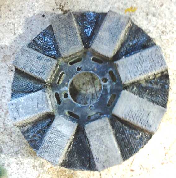 So on the
afternoon of the 22nd I spent a couple of hours
milling slots in the rotor so I could wrap the magnet strapping around
the magnets and rotor, and another hour prying the steel filings off
the magnets
and then sanding them rough so the fresh epoxy would adhere. I just
"eyeballed" the small slots, trusting they'd be close enough. The next
day (23rd) I sanded the weak zinc coating (and the paint over it) off
the back of the rotor with the belt sander to give the epoxy a good
grip on the steel back. Then I cut the strapping, folded it in thirds
and fed it through the slots (dry), and then epoxied it into place.
When I had done the magnet side I flipped it over and did the back. I
positioned the straps where they should be, put some thin PE sheet over
each one, and put on some little steel weights that I have. I put an
aluminum disk over the whole thing and put a heavy weight on top. I
left it to set undisturbed, since everything would probably shift while
moving it to the oven, and there was no rush.
So on the
afternoon of the 22nd I spent a couple of hours
milling slots in the rotor so I could wrap the magnet strapping around
the magnets and rotor, and another hour prying the steel filings off
the magnets
and then sanding them rough so the fresh epoxy would adhere. I just
"eyeballed" the small slots, trusting they'd be close enough. The next
day (23rd) I sanded the weak zinc coating (and the paint over it) off
the back of the rotor with the belt sander to give the epoxy a good
grip on the steel back. Then I cut the strapping, folded it in thirds
and fed it through the slots (dry), and then epoxied it into place.
When I had done the magnet side I flipped it over and did the back. I
positioned the straps where they should be, put some thin PE sheet over
each one, and put on some little steel weights that I have. I put an
aluminum disk over the whole thing and put a heavy weight on top. I
left it to set undisturbed, since everything would probably shift while
moving it to the oven, and there was no rush.
Slots milled, and everything
cleaned off and
sanded
Finished upgrade, except some of the epoxied
fabric corners stuck out too far and
had to be snipped off with side cutters.
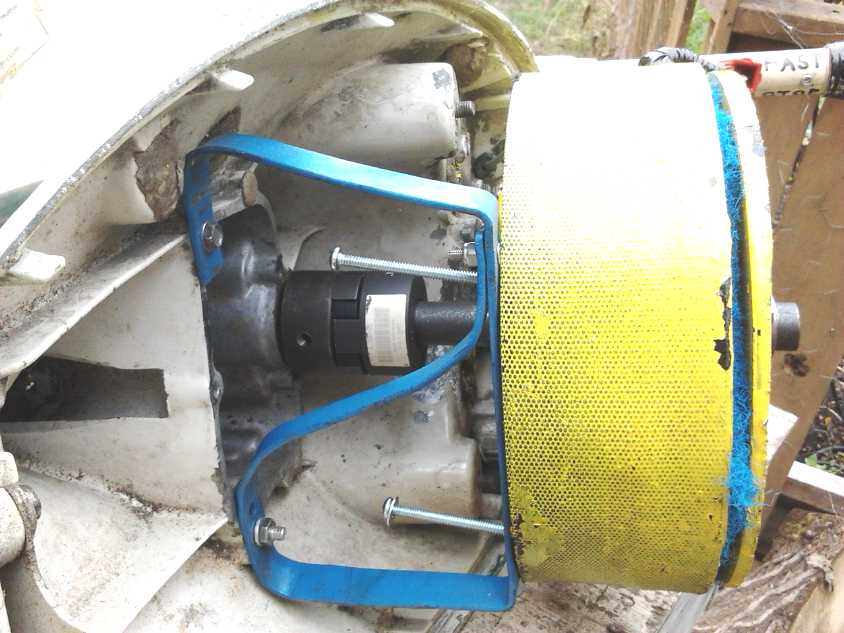 Checking the fit of the motor in the outboard.
But several things then came up and I didn't get the Caik
motor completely reassembled and back in the outboard by month's end.
After taking the (Electric Hubcap) motor stator apart and
reassembling it 3 times
(not to mention probably previous times in years back), some of the 27
bolt holes holding the stator compartment together seemed to be
stripped, the machine screws refusing to tighten. I really ought to
stuff some epoxy and bits of polypropylene cloth into the holes, then
re-drill the holes out to repair them... Or maybe drill them out larger
and put in 1/4" nylon screws that would have no electromagnetic heating
effects? I went to the drawer of plastic screws. There were just 9. The
Hubcap motor would need 27. The Caik motor would need 18. But there was
a box of longer ones that could be cut down. But this work too was
halted until October.
Gear Cutters
The set of gear cutters arrived on the 13th. They came
with 27mm keyed holes in the middle. I scrounged a 1.25" x 2.5" piece
of stainless steel shaft to make a center axle for them that would fit
in the milling machine's largest collet chuck, and turned it to fit the
same day. On the 15th I added a 1/4" machine screw hole to screw on a
washer so the cutter couldn't fall off the end, and a shaft keyway so
it couldn't slip instead of turning.
Jumping ahead, I noticed the cutter had some wobble to it,
and on the 21st I did some more work on it. I had to trim it down from
5/8" to 9/16" collet chuck size. I got it pretty true.
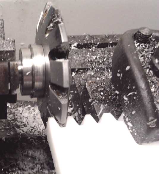 The rotary
table and dividing plates still hadn't arrived (and didn't during
September),
so I couldn't make an actual gear. I mounted a piece of plastic in the
tool holder on the lathe and cut a few sample teeth. The plastic cut
like butter, and my estimation of the practicality of making plastic
gears went way up. OTOH, it had better not break or wear down as
readily as it cuts! Someone in a video took apart a piece of equipment
in which he thought its nylon gear would surely be worn down. But it
still looked like new, and if anything, he said, the brass gear it
meshed with looked slightly worn. This is encouraging!
The rotary
table and dividing plates still hadn't arrived (and didn't during
September),
so I couldn't make an actual gear. I mounted a piece of plastic in the
tool holder on the lathe and cut a few sample teeth. The plastic cut
like butter, and my estimation of the practicality of making plastic
gears went way up. OTOH, it had better not break or wear down as
readily as it cuts! Someone in a video took apart a piece of equipment
in which he thought its nylon gear would surely be worn down. But it
still looked like new, and if anything, he said, the brass gear it
meshed with looked slightly worn. This is encouraging!
Gear Making Calculations
Later on the 15th I looked up how to do gear making
calculations.
From the Website:
http://khkgears.net/gear-knowledge/gear-technical-reference/calculation-gear-dimensions/
(From Japan. They still make things in Japan?)
Gear dimensions are determined in accordance with their specifications,
such as Module (m), Number of teeth (z), Pressure angle (a), and
Profile shift coefficient (x). This section introduces the dimension
calculations for spur gears, helical gears, gear rack, bevel gears,
screw gears, and worm gear pairs. Calculations of external dimensions
(eg. Tip diameter) are necessary for processing the gear blanks. Tooth
dimensions such as root diameter or tooth depth are considered when
gear cutting.
4.1 Spur Gears
Spur Gears are the simplest type of gear. The calculations for spur
gears are also simple and they are used as the basis for the
calculations for other types of gears. This section introduces
calculation methods of standard spur gears, profile shifted spur gears,
and linear racks. The standard spur gear is a non-profile-shifted spur
gear.
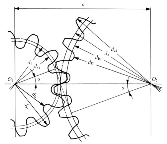
(1) Standard Spur Gear
Figure 4.1 shows the meshing of standard spur gears. The meshing of
standard spur gears means the reference circles of two gears contact
and roll with each other. The calculation formulas are in Table 4.1.
Fig. 4.1 The Meshing of Standard Spur Gears
( α = 20°, z1 = 12, z2 = 24, x1 = x2 = 0 )
Table 4.1 Calculations for Standard Spur Gears
NOTE 1 : The subscripts 1 and 2 of z1 and z2 denote pinion and gear
All calculated values in Table 4.1 are based upon given module m and
number of teeth (z1 and z2). If instead, the module m, center distance
a and speed ratio i are given, then the number of teeth, z1 and z2,
would be calculated using the formulas as shown in Table 4.2.
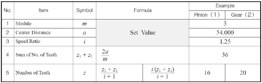
Table 4.2 The Calculations for Number of Teeth
Note, that the number of teeth will probably not be integer values when
using the formulas in Table 4.2. In this case, it will be necessary to
resort to profile shifting or to employ helical gears to obtain as near
a transmission ratio as possible.
(2) Profile Shifted Spur Gear (Huh? More than I want to know... I hope!)
I decided that the next thing I should do would be to cut
a pair of sample gears... but the rotary table and dividing plates
hadn't arrived yet. Well, at least I could calculate them. The cutters
were M4. I presume all the dimensions are in millimeters. How about a
16 and a 27 tooth gear pair, just for somewhere to start?
So per the illustration 4.1:
1. M = 4
2. alfa = 20°
3. z1 = 16 z2 = 27
4. center distance (16+27)*4/2=86mm
5. reference diameter d = zm: 16*4=64; 27*4=108 (wasn't that easy!)
6. base diameter = d*cos(alfa): 64*cos(20)=60.14; 108*cos(20)=101.4868
(also simple... with a calculator)
7. addendum 1*m: 4; 4
8. tooth depth h = 2.25*m: 9; 9
9. tip (outermost) diameter da = d+2*m = 64+8=72; 108+8=116mm
10. root diameter df = d-2.5*m = 64-10=54; 108-10=98.
4. z1 + z2 = 2a/m = 2*101.6/4 = 25.4 teeth. Hmm, that might not be very
convenient. Let's make it 100mm and hence 25 teeth.
Apparently these teeth can be divided as desired between the 2 gears.
But that's not very many teeth!
For 16 teeth, 360/16 is 22.5 degrees between teeth. One would use
cutter #2 (of 8), for gears with 14 to 16 teeth.
For 27 teeth, 360/27 is 13.33333 degrees. Use cutter #5, gears 26 to 34
teeth.
Starting from a disk of diameter da, one would cut in each tooth until
the inner diameter was down to df. The reference diameter of of the 27
tooth gear is over 4". A 60 tooth gear would be almost 9.5". Excellent!
Gears with the large M4 teeth I chose to buy (it was just a rough
guess) are big in diameter. That's exactly whet I wanted to make: big,
fat plastic gears. They should handle the forces involved in moving
cars by virtue of their size reducing the loading at all points. At
least that's my plan! And UHMW gears will be as slippery as teflon
(PTFE), so they should be very low friction with little to no heat
buildup, and low noise.
So, that's 43 total teeth, so the reference diameter between axle
centers with M4 teeth is
43*4=172mm. The speed ratio is 27/16=1.6875.
A differential gear unit composed of spur gears only
(below)
solved a key problem of having to make either a planetary type gear
with
an inside ring gear, or a differential gear with beveled
gears. It somewhat belatedly occurred to me that I can't fit
the milling machine into the inside of the ring to cut inside teeth,
and I expect beveled gears require more than just the simple
cutters, too. Now only spur gears will be needed. I'm counting on the
plastic material to make them as smooth and quiet as metal helical
gears... or at least smooth and quiet enough.
For this, I chose a ready-made housing, to hold 50 and 47 tooth m4 main
gears. The gear diameters are:
50*m=200mm (~7.8"), and
47 teeth, 188mm (7.4").
That should leave room for the configuration discussed below.
Other ways to Make Plastic Gears!
I already knew the 3D printer was out. The materials
available weren't strong, slick UHMW, and finished pieces weren't as
strong as those made from any solid plastic. The surfaces were rough,
and they would quickly fall apart if handling stresses.
Well, I had bought the stuff, looked up the instructions,
and did the calculations above. I followed all the 'regular' steps and
was merely waiting on the rotary table and dividing plates. After all
that, late in the evening (still the 15th) it occurred to me to look at
youtube and search for plastic gear making.
The first thing that occurred to me as I looked down the
list of choices without even watching any of the videos was that those
rather large teeth could doubtless be molded instead of milled. In a
video - just the thumbnail image - the person was casting gears of
epoxy(?) in rubber moulds. Instead
of a rubber mold I could make one injection mold for each desired gear.
(for a production model)
Then they could be mass produced in UHMW. I would only have to make an
inside-out gear for the mold. (Now there's a way to make an inside ring
gear... it would be on an outside! But then what about all the other
gears?) Injection moulding would allow for more complex shapes, such as
a ring gear with gears inside and out.
Next I went to a simple 78 second video titled simply
"Making Gears Outta Plastic". No voice, just music... and just
about fell out of my chair! A big gear with 17 big teeth was being cut
out of a fat piece of UHMW by a CNC router much like mine! What could
be simpler to do, or (for me) require less investment in equipment?
Forget the involute gear cutter set I'd just spent hours making a
mandrel for, forget the rotary table and dividing plates. It could all
be reduced to numbers in a spreadsheet or CAD program, and a 1/8"(?)
router bit with a long shaft! Inside and outside gears could be cut!
A 1/8" router would make for slow cutting, but it would be
the largest router that wouldn't horribly deform "m4" gear teeth. They
might still be a bit distorted right at the inner tips of the spaces
between teeth.
Now, if only I had started thinking about alternatives and
watched those youtube videos before I ordered all the gear
making stuff!
Then I started thinking about how hard all that math would
be for the shapes. What if I used OpenSCad to design the gears,
designing only a single layer thick, and then ran Pronterface as if I
was going to print it to the 3D printer (and maybe actually print, just
to see it). I could then take the G-code file generated by Pronterface
and... wait a minute... Pronterface wouldn't account for the diameter
of the router bit. I should probably order the 800$ "Rhino Express"
that Victoria Waterjet uses. Yikes! Canada Revenue hadn't come through
with my refund for 2015 yet (it did arrive later) and not to mention
credit card debt, my bitcoins were disappearing rapidly.
I wished I'd bought that instead of all these metal gear making tools.
Spur Gear Differential Gear & Variants
On the 17th I searched for differential gears on the web
- thinking perhaps to buy - and came across (wouldn't you know it?)
Wikipedia. Once again I was
surprised by finding something I had had no inkling existed: the first
image in the article showed a differential gear made entirely of spur
gears - no bevel gears, no inside ring gear. (Beautiful pencil sketch!)
Thus it would be much
easier to make if one is making the gears. Or one might buy the simple
gears that make it up. If one wants the "no
lube" effect of
plastic, big steel gears could be purchased and the small ones done in
plastic. In the drawing, it looks like one could fit 6 or 7 pairs of
planetaries around the perimeter to spread the loads out.
It's sort of a variation of what I called the
"double sun
planetary" I had conceived a few months ago. (I already suspected the
gear arrangement I "invented" could hardly be very original in a well
explored field like gears!) Doing the planetaries in counter-rotating
pairs to make two equal ends at 1 to 1 ratio, and having all three
elements rotating the same way, is one more demonstration that there
are
mechanical geniuses out there. (But it's my differential
variable
transmission idea, arf! arf!)
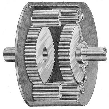 A spur gear differential constructed by
engaging the planet gears of two co-axial epicyclic gear trains.
A spur gear differential constructed by
engaging the planet gears of two co-axial epicyclic gear trains.
The casing is the carrier for this planetary gear train.
(The planetaries turn against each other in pairs as well as against
the
sun gears.
That's why the teeth extend into the middle. It took me a bit to figure
this out.)
The fixed drive would turn a gear or sprocket on the
outside of the casing. Now, we don't need symmetry for the differential
transmission. If one side had a larger sun gear than the
other, its planetaries would turn outside the limit of the other gear,
and their teeth could go right across. The other sun gear would have
narrow "planetaries" connecting it to the outer ones. The sun gears
could then be
adjacent with just a tiny gap, narrowing the profile. It would also
be a differential with a different ratio between the two sides.
Probably one end could be given the reduction ratio wanted for the
variable drive. But the
larger the difference between the two sun gears, the larger the planets
of the smaller one would have to be for their axles to clear the larger
one - unless their axles didn't go across to that larger gear.
Hmm!
Maybe my own 'double sun' version would be better for the transmission?
There's one less set of meshing gears, and the shell rotates the
opposite direction, like a planetary gear. Later I realized that was
what the choice was: if one drive turned in the opposite direction to
the other (eg, one was driven through a pair of gears, causing its
direction to reverse) one would want my configuration, but if both
drives went the same way, the modified differential would be the choice.
But whatever the exact gear configuration inside, I like
the case layout. Somehow I was still wondering how to
mount my gears of this form, and this is the now obvious solution.
Configuring a Production Model
From the various bits, pieces and ideas, by the 20th I
started considering how a production model might actually be
configured, and "mocked up" the layout with the various potential
components or substitutes for them on a piece of 11" * 17" paper. There
are four main components within the case:
* The motor shaft
* The main differential/planetary/epicyclic gear (hereinafter
"the differential". The "slow speed" end is the output shaft.)
* The fixed drive from the motor shaft to the differential
center/case (gear, chain or belt)
* The variable drive from the motor shaft to the "high speed" end
of the differential (variable pulley belt plus gear, chain or belt
reduction - or - variable pulley belt with internal reduction in the
differential unit). A control lever sticks out of the case to control
the pulley and hence the final drive ratio.
If the differential has the reduction built into it,
there's no need for a chain drive reduction. And it would be
undesirable since it needs lubrication. Why then would there be a third
shaft? The next morning I had the potential answer: an idler pulley on
a stiff arm could set the ratio, being variably inserted to force the
variable pulley to smaller diameters. But on checking it out with the
actual pulleys and belts, I found that the difference in belt length
between fully out and fully in was so great that an idler would have to
push the belt in so far it would hit the other side of the belt and
more. An idler pushing outward might work in theory, but mostly it
would only serve to reduce the grip of the belt on the pulleys and
probably make it slip. And like a third shaft, it would create a "knee"
forming a triangle which would make the whole thing bulkier.
Reducing to one variable pulley for a production model
started to sound rather tricky after all. Maybe a longer belt to make
room for two idler pulleys for the belt to 'wrap around' - one in, one
out? Those could be on a single pivot pin, which would pivot on a
common center, twisting the belt between the two idlers to pull it in
and change the variable ratio. Hmm, that would twist the belt too much.
I decided the third shaft would be needed after all. But
instead of a chain, I would prefer to use plastic gears if possible.
When I layed out the components I found that if I made the gear drive
go to the motor shaft and the belt drive go to the differential, the
pulleys wouldn't stick out farther than the 10" differential required
anyway,
and so the shape could be rectangular. But it proved more practical to
have the reduction external to the differential, so that wouldn't work.
The bulge would have to stay... unless a short variable belt with just
the right size of pulleys could be fit in.
Perhaps interestingly the differential could pretty easily
be made as a sealed oil bath type unit with metal gears
if desired. I thought of the Raybestos brake drum I had used long ago
in an attempt to make a centrifugal torque converter. It had one solid
steel
side and a thick solid steel rim. I found this hacked-up part at the
bottom of the
shelves and pulled it out. (What a junk collector I am! I was unable to
find a second one I thought I had - must have tossed it?!?) If the
inner
rim was turned off on the lathe, a round disk of steel plate could form
the
other side and be bolted securely into exact place for the center
bearings and planetary axles to go straight across. It was just big
enough to hold some good size gears about 5/8" wide. I would have liked
wider. It might need those metal gears. It seemed
awfully heavy, but so was the casing on the original planetary gear on
the car. Given the torque and radial forces, this case needs to be
very stiff. So this unit should be excellent for a prototype - perhaps
even for a production model. (The Raybestos model/part number is in
some
ancient issue of TE News or old motor making manual.)
Or, I have a couple of pieces of aluminum pipe, 9" and 10"
diameter and 3" or 4" long. And at least the 9" can be bought readily.
With aluminum, turned to fit (and maybe one side welded on), they'd
hold wider plastic gears. And they'd be lightweight. Then again, steel
is stronger... I should stick with it. And the brake drum is already
precision turned. If I make the precision planetaries axle holes by CNC
waterjet in the plate for the second side, I can use it as a template
to drill out the ones in the drum.
Another thought is that the cast Raybestos drum is 10"
O.D, 1.75" wide, flat on the outside and has a rough finish. Is this
not ideal to be turned by a fat 99% efficient flat belt instead of
either a gear or a chain? No extra width for that! (Or if that slips,
the rim is thick enough to cut toothed belt teeth into.) In fact, 2 of
the 5-V poly-V belts I already have one of, driven by 2 poly-V pulleys,
might be about right. On the 30th I bought a 2.75" poly-V pulley for
it, giving a reduction of about 3.5 to the drum - not dissimilar to the
3.0 of the chain on the Sprint. It starts to look doable!
There'd have to be some serious calculations to
have all the gear sizes, case size, belt lengths and overall chassis
size and shape come together. Maybe mock-ups, incorporating some paper
or cardboard, as a reality check on them. But perhaps this whole
'production model' thing might start to
come together in a relatively doable form after all?
2nd "Mock-Up", with variable
belt to differential unit & fixed drive to input shaft.
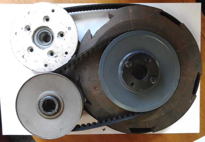 I started a "mock-up" on the 20th with an overall chassis
layout using all the parts I had tentatively determined on. Allowing
for a 'Raybestos' 2.5" wide differential/epicyclic gear, bearings and
the variable
pulley, I came up with about 5.5" thick, by 13" wide by 16" long -
inside
dimensions. The width was allowing for a third shaft with a 6" pulley
and a gear pair (one gear represented by the off-white circle) driving
the end of the epicyclic gear. But really that width only needed to be
a bump in the side of an 11" wide space. And of course measures like
rounding the ends could further reduce the overall profile.
I started a "mock-up" on the 20th with an overall chassis
layout using all the parts I had tentatively determined on. Allowing
for a 'Raybestos' 2.5" wide differential/epicyclic gear, bearings and
the variable
pulley, I came up with about 5.5" thick, by 13" wide by 16" long -
inside
dimensions. The width was allowing for a third shaft with a 6" pulley
and a gear pair (one gear represented by the off-white circle) driving
the end of the epicyclic gear. But really that width only needed to be
a bump in the side of an 11" wide space. And of course measures like
rounding the ends could further reduce the overall profile.
If the 'flat' belt is a poly-V belt like the one shown (or
two side by side for more strength and better grip), the small
pulley(s) could easily be a genuine poly-V pulley, which would keep the
belt in line on the large flat surface. (I don't envy the person who
has to change the flat belt. One side of the unit will have to come
right off.)
Soon I noticed that if the gears went to the motor shaft
and the variable belt part to the differential shaft, instead of the
other way around, it could be reduced to 11" wide (needed for a 10"
epicyclic gear regardless) because the motor shaft was offset from the
center, leaving more room. And then with a slightly longer belt than I
had, the protrusion (gear attachment permitting) could be pointed
inward to chop an inch off the thickness to 6": 16" x 11" x 6". If not,
perhaps the protrusion could just be a bulging arc cover?
I started thinking about
the many innovations, that there
were so many of them in one project. Too many? Anything that didn't
work could
set things back considerably. The first thing was making plastic spur
gears for the differential. Should I just buy some metal gears for the
first tests? I thought about that until the 21st, when I found that
cutting plastic gear teeth was simple - the UHMW plastic cut like
butter. (except for a bunch of shavings to trim off
after) So I decided to do it the other way around: go with plastic
gears unless they definitely didn't work. A 6" diameter gear 1.25"
wide, with 6 planetaries compared to a steel sun gear from a Chrysler,
would be, um:
diameter: 45/152.4 = .295
width: 15/31.75 = .472
planetaries: 4/6 = .667
Total relative loading: .295*.472*.667=.0929, or 9% as much force on
the large gear teeth surfaces as on the small commercial ones. That
sounds promising in itself. However, it has to be tempered by the fact
that it's our output gear, whereas in the Chrysler it still goes (at
the least) through some final reduction gear before the wheels. The
tentative conclusion is that unless there's a final reduction to the
car wheels, the gear might not be strong enough. One could of course
incorporate the 3 to 1 chain reduction in the Sprint now following the
variable transmission (or something similar in another vehicle) to
achieve that end, perhaps running 1 to 1 (minimum reduction) through
the variable transmission part. That would allow driving both wheels
again.
A better comparison might be with the gears out of the
Sprint manual transmission. All five gears plus reverse run on the same
shafts, with only one meshing connection between each input and output
gear, and they're followed by a 4 to 1 final reduction to the
differential gears before the wheels. I didn't get these out to check
by the end of the month, but they seem to take a lot of torque for a
small size.
With the 'brake drum' body for the differential the gears
could only be about 15mm wide. OTOH the large gear could be up to
almost 8". These would modify the force per gear tooth area
calculations somewhat. On the 25th, I thought of expanding the whole
thing to use a 3" wide * 12" diameter differential, allowing very large
and wide plastic gears. But I went back to the solid, already made and
machined Raybestos drum.
Considering the differential gear element
spacings, I decided I would make an 8", 50 tooth large-end sun gear,
leaving just enough radius outside for the planetaries, and a 47 tooth
small end. I would have liked to go much smaller for an internal gear
reduction from the variable belt driven end, but by making it just a
bit smaller than the other, the axles for its planetaries could go
right across without hitting the large one, simplifying construction.
The speed reduction can almost as easily be external.
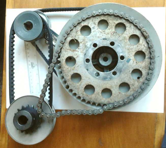 I reluctantly
concluded that to do that, at least for the
prototype, I should use a chain drive. A gear drive would reverse the
direction, and I decided that the unidirectional differential would be
easiest to make. (For a production model, one might use three gears
instead of two to double reverse the direction, and the mid gear might
also take it sideways, which could shave a layer off the overall
thickness, potentially bringing it down to around 4".) With the last
mock-up on the 30th I decided to add a inch to the width, and it looked
like I could take one off the thickness and make it rectangular, 12" *
16" * 5" - inside dimensions. Maybe with the bulge for the variable
pulley.
I reluctantly
concluded that to do that, at least for the
prototype, I should use a chain drive. A gear drive would reverse the
direction, and I decided that the unidirectional differential would be
easiest to make. (For a production model, one might use three gears
instead of two to double reverse the direction, and the mid gear might
also take it sideways, which could shave a layer off the overall
thickness, potentially bringing it down to around 4".) With the last
mock-up on the 30th I decided to add a inch to the width, and it looked
like I could take one off the thickness and make it rectangular, 12" *
16" * 5" - inside dimensions. Maybe with the bulge for the variable
pulley.
I couldn't make gears until the rotary table and dividing
plates arrived. But I had them pretty much sized up. It seemed the next
things to do were to were to find roughly 3.3" pulleys for the poly-V
belts, and when I had all the dimensions to start laying out the steel
plate parts for the other side of the drum and the outer case.
From about the 25th I
started hunting for a new computer
to run "Rhinoceros 3D" CAD program for designing these metal parts, to
be cut by CNC waterjet. (also to run "Sibelius 8" music notation
program for composing orchestral & concert band music.) Newer
versions of those won't run on my old Mac and of course they don't
offer any of the older versions that did and still would if I could get
them. And there are no Linux versions. (The one I wrote my music with,
"Overture 2", which was a great program, has been unsupported since USB
was created, and doesn't run on any newer computer or O/S.) A
knowledgeable friend said Windows software can be run under Linux and
had no reservations about being able to get them going. So I got a new
(used) box that's actually running Linux. But it has much more memory
and CPU power than my old Linux laptops.
While we were setting it up we found "MuseScore" and
installed that. IF I find when I have time that it'll do the job I can
skip buying Sibelius. And "Blender 3D" was mentioned. IF that'll do the
job I may pass on Rhinoceros too. Those would be big savings over the
commercial software even if I donate pretty nicely to the creators - as
was buying a 'government surplus' used computer.
As I wrote this, I thought again of "OpenSCad" that I
already use for the 3D printer. When you're starting with numbers,
positions and sizes, it's quite easy to just enter numbers and hit
"render" to see the result. No learning curve. OpenSCad is after all,
open source, and theoretically I could make a version, or a ".DXF" file
exporter, that (as required by Victoria Waterjet) defines curves (as
you originally define them) instead of converting them into a series of
short straight line segments. But the learning curve for doing that
programming would surely be beyond anything I'd want to attempt. And it
wouldn't help for doing CNC router porjects where the diameter of the
router bit needs to be taken into account.
Electricity
Generation
Conversion of
Car Alternator to Permanent Magnet Alternator
I started this thinking I'd want an alternator(s) for
testing wave power units. The wave power has been put aside, but having
started on the alternator, and it showing the promise of being a small
project that could be completed quickly, I thought I would finish the
conversion. Then I might try it out, perhaps as a small hydro generator
with a primitive
pelton wheel, just with the garden hose. (Maybe in a windplant? Well,
later!)
The trouble with car alternators as alternators/generators
for windplants and the like is that they have a 'field coil'
electromagnet in the armature, which is what the brushes power. This
uses power. The more the desired voltage per RPM, the more current has
to go into the field coil to give it more magnetism. In one alternator
I measured 3 amps at 12 volts, or 36 watts, being consumed by this
coil. That's probably the maximum, but if you don't use that, you need
some way to give it some lesser voltage. And then it will need higher
RPM to get the same output. If your small windplant is making 50 watts
in light wind at a lower RPM, consuming 36 watts would only leave 14
watts output.
A permanent magnet on the other hand uses no electricity,
so the whole 50 watts is available. If a 'supermagnet' (eg an FeNdB
'neodymium' magnet) is used, the flux should be very high, giving
maximum power per RPM. The disadvantage is that its voltage (and the
current capacity) rises linearly with the RPM. Typically it won't work
at all until the RPM is high enough to give voltage higher than
batteries being charged, and above that it will put more and more
current into the battery regardless of its state of charge. I put a
very powerful ring magnet in in place of the coil. I thought it would
probably
give more volts per RPM than the coil at full strength.
There are other ways to regulate output voltage (once
rectified to DC) for battery charging or other load. A DC to DC
converter with a fairly wide input range will go a long way toward it.
And maybe when it's done, the infinitely variable transmission
(probably under computer control) can have it maintain some desired RPM
and hence
output voltage level regardless of propeller (or other input) speed -
and within limits of available input power, regardless of varying
output loads.
Many conversions are done by replacing the entire
armature, with one having supermagnets spaced around the outside facing
the coils in the typical 3 coils per 2 magnet poles 3-phase
configuration. This technique also works for most any three phase
induction motor. The biggest problems are making the new armature,
making it solid enough that it won't fly apart at higher RPM.s, and
that ideally the magnet outer faces should be curved to match the
diameter to get close magnetic coupling.
My plan for
this conversion was a little different:
Replace the toroidal electromagnet coil in the armature with a toroidal
(ring, donut) shaped supermagnet. The rotor's soft magnetic 'petals'
would be the alternating north-south 'facing magnets' as before,
carrying the magnetic field of the magnet in the center. Since it was
unchanged, they would be the right number of magnets, spacing and flux
gap to the stator. It sounded really simple, but the details concealed
devils. The first one was getting the old thing apart, which wasn't
trivial as described last issue. The second one was to fit the magnet
into the unit when it had a different inside diameter than the coil.
On the 5th I went to turn down the 'coil center cylinder'
pieces that
were inside the coil. They were too large in diameter for the magnet
with its smaller center hole, and I figured they'd short out its
magnetic field. (hmm, I think I have that wrong?) So I was going to
turn
away most of the center iron from inside the coil on the lathe, just
leaving a 1" diameter by 1/8" round 'button' on each end to mount the
magnet on.
But owing to various protrusions there didn't seem to be
any way to attach the pieces to my small lathe. I had to go down to AGO
the next day and get machinist Ralph to do it for me on a very large
lathe with a big chuck that could grab it around the outside without
bending the fan blades. I had hoped this could be a home project for
any handyman. It was certainly not in my thoughts that I'd have to have
outside help myself! (The mid-size lathe at Makerspace might have
worked, but I wasn't at
all sure it was big enough, and I didn't want to drive all the way out
there only to find it wouldn't. I had already spent 2 hours in
surprisingly heavy midday traffic to get to just a couple of places,
once again double the time it should have taken.)
Pressing bearing back into
housing.
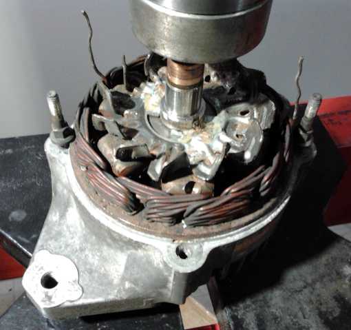 On the 7th I
pressed the armature back onto the shaft. The
first time I didn't quite get it to the end, and the case wouldn't fit
back on. The second time I put too much pressure on it and the needle
moved on the gauge. (A ton?) Then I remembered it was the ball bearing
I was pressing on. It dented the race or the balls and now it runs
rough.
On the 7th I
pressed the armature back onto the shaft. The
first time I didn't quite get it to the end, and the case wouldn't fit
back on. The second time I put too much pressure on it and the needle
moved on the gauge. (A ton?) Then I remembered it was the ball bearing
I was pressing on. It dented the race or the balls and now it runs
rough.
But that wasn't the only problem closing the case. The
coil had been 24mm wide and the magnet was 25.4. Furthermore, Ralph
couldn't quite get to the bottom, so there was an extra millimeter of
thickness at each end. I could see that the fan blades hit the end
before it closed together. I opened it again and took out a 6mm thick
washer I was now sure would prevent it from closing, and I bent the fan
blades. In doing that they swung outward a bit and wouldn't go past the
stator. I snipped the protrusions off. It still didn't turn and I
hammered the blades down some more. Now they were well recessed (and
would move ~1/4 as much air) but it still didn't turn. Then I realized
some of the fan blades on the other end were bent and hitting the
connection wires where they passed by. I stuck in a screwdriver and
bent them straighter again.
When I had it together there seemed to be too much
friction. I tried more than once to take it apart and redo it, to no
avail. All I accomplished was to break a minor crack in the housing. I
think it's magnetic friction, in spite of there being no
apparent cogging. (Unless I did actually bend the shaft a bit when I
took it apart. But it seems too uniform all the way around for that.) I
put the
poly-V belt pulley back on the shaft, and with the extra grip of the
pulley instead
of just the shaft, it was easier to spin and didn't feel absurdly
stiff. It still came to a stop within about half a second when spun.
The next morning it seemed better all by itself - anyway better than
the
lawnmower motor, my other sample of a smallish permanent magnet motor.
Were my expectations just too high? I guess the magnetism is bound to
make for some friction compared to something without magnets in it. The
alternator shaft attracts steel pieces. Not quite satisfied yet, I
removed the brushes from the lawnmower motor. Now the drag was
comparable. Must be an inevitable magnetic effect. Freely as it spun
before the conversion, it doubtless would have had a similar drag
effect running with the electromagnet on, so really no efficiency has
been lost in the conversion. However I do believe it's possible to make
permanent magnet motors and generators that don't have this drag by
careful design. It seems to me I've seen some very large ones that turn
considerably more freely.
Spinning it
14 volts DC at 20 amps continuous when rectified seems
reasonable for a small car alternator. That would be 280 watts or 1/3
HP. You wouldn't turn that power by hand, and not for long with bicycle
pedals! With a 24/7 driving source, that would be a lot more, more
reliable overall power than a 260 watt solar panel.
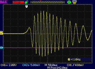 By
giving it a spin it by hand, with the oscilloscope connected between
two phases,
it produced about 12 volts peak to peak at about 50 Hz.
By
giving it a spin it by hand, with the oscilloscope connected between
two phases,
it produced about 12 volts peak to peak at about 50 Hz.
Project Creep!
Effectively the project was finished: I had converted the
alternator. Of course, I had
no idea what RPM it got up to or how it might perform. It needed to be
connected to a motor and
spun at a steady speed. Uh-oh! This was supposed to be a short, simple
project! But what was the point to converting it without testing it to
see how good it was?
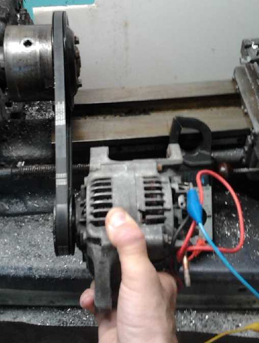 In order to do that, on the 8th I dug out a
poly-V belt
pulley from the Sprint engine parts that matched the alternator's
pulley, and cleaned the thick grease off it. (yuk!) Then I did
likewise, as best I could, to the belt. (And I wish I had cleaned the
alternator better when I had it apart!) The pulley was the water pump
pulley, and it had no center. I thought, what better center than the
shaft and end off the water pump? I went out to the engine and removed
the water pump. That started a whole comedy of events. I couldn't get
it apart. Trying to press the shaft out, the case cracked and half of
it flew out of the press. (And here I had neglected to put on safety
glasses!) Then I figured if it was that flimsy, I would hammer it apart
on a rock with a big maul. With safety glasses on, I took a swing.
Nothing broke. Instead the pump flew straight at my shin, leaving a
good bruise. I gave up for the day. The next day (9th) I started
cutting the 'pot metal' case apart with the angle grinder. With a slit
down each side it finally snapped apart when hit with a hammer onto a
screwdriver in the biggest slit. Even then, the shaft still had two big
bearings covering its whole length and seemingly no possible way to
press them out. I finally had to cut these apart as well, and then I
finally had my shaft with attached pulley mounting. I think it would
have been easier to make one from scratch.
In order to do that, on the 8th I dug out a
poly-V belt
pulley from the Sprint engine parts that matched the alternator's
pulley, and cleaned the thick grease off it. (yuk!) Then I did
likewise, as best I could, to the belt. (And I wish I had cleaned the
alternator better when I had it apart!) The pulley was the water pump
pulley, and it had no center. I thought, what better center than the
shaft and end off the water pump? I went out to the engine and removed
the water pump. That started a whole comedy of events. I couldn't get
it apart. Trying to press the shaft out, the case cracked and half of
it flew out of the press. (And here I had neglected to put on safety
glasses!) Then I figured if it was that flimsy, I would hammer it apart
on a rock with a big maul. With safety glasses on, I took a swing.
Nothing broke. Instead the pump flew straight at my shin, leaving a
good bruise. I gave up for the day. The next day (9th) I started
cutting the 'pot metal' case apart with the angle grinder. With a slit
down each side it finally snapped apart when hit with a hammer onto a
screwdriver in the biggest slit. Even then, the shaft still had two big
bearings covering its whole length and seemingly no possible way to
press them out. I finally had to cut these apart as well, and then I
finally had my shaft with attached pulley mounting. I think it would
have been easier to make one from scratch.
I found 4 bolts that fit it in the Sprint bolts box and
put
it together.
Converted Alternator Performance
The shaft was too big to fit in the drill press chuck, but it fit
in the lathe chuck. I set the lathe to medium speed, put the belt on,
and simply held the alternator in the correct position with the belt in
line and relatively taut. Calculating from motor speed and pulley sizes
of 3 sets of pulleys, I got the following result between two phases:
18.5 VAC (RMS), 228 Hz, at a calculated 2435 RPM. The frequency
doubtless indicates it was actually 2280 RPM. Shorting two wires
together (through a light alligator clip test lead) gave about 18-19
amps AC. Presumably shorting all the outputs would have yielded more.
(I forget the math - 19 * sqr.root of 2 = 27 Amps AC? or was it
sqr.root of 3?) That probably means you could get the 20 amps at 14
volts DC after it was rectified - at 2280 RPM. Higher RPM would give
more potential, but at some point it will overheat. The poly-V belt
pulley sizes raised it from 1068 RPM to 2280 with no gear noise and
probably quite low losses, so that would be the way to go with a lower
RPM energy source, rather than trying to find a lower RPM alternator.
I reduced the lathe speed and got 10.4 VAC at 130 Hz/1300
RPM. 10.4 * 2280/1300 = 18.24 VAC, the voltage measured at 2280 RPM,
demonstrating that voltage is indeed linear with RPM. (It's probably
even closer than the calculation - the RPM.s aren't exact... from the
meter reading jumping between 228 and 229, and 129 and 130, I estimate
they were probably closer to 2282 RPM and 1296 RPM. And the voltages
only had one decimal point on this meter too.)
It seems in line with the
performance I'd expect from this
small alternator, but without wasting maybe 20 or 30 of whatever watts
were generated to activate the field coil. Thus, it seems like a good
way to convert a car alternator to permanent magnet. It probably took
too long and cost too much for a one-off unit that I have no
particular use for with the wave power project set aside.
Other options would be of course a 120V, 12A lawnmower
motor, which would need no conversion, or perhaps to build the
frictionless Scorag/Piggott axial flux windplant's alternator from
scratch or from
available kit components. Those run at good lower RPM.s for a typical
small windplant. Or maybe there's good PM alternators or generators for
sale at good prices these days, perhaps from China?
Is it a way someone might earn cash?
I have the thought that someone might get good at taking
alternators apart and fitting them with ring magnets, then selling them
to people who want to make energy generating devices. If one had it
down pat, and found which models converted the most easily, it
shouldn't take so long to do one. It would be simpler and
cheaper than converting induction motors. To do it, one would need a
press, a lathe, a source of cheap alternators, and to buy a supply of
ring supermagnets. Don't try to convert a very small alternator like
the
Sprint's with a coil thinner than the magnet. Expanding the armature
length just makes for much fiddling around to get things to fit. If the
coil is thicker than the supermagnet, leave some extra metal when
turning down the inside so that the armature size doesn't change.
But I would see it as a means to an end, that it might
open up further opportunities. For more value added, make whole energy
generator units
like VAWT.s or pelton wheels and sell the whole thing? (Aren't there
any good small VAWT.s for sale commercially - just buy and hook up?
There must be a market! Days later: gosh, see below!)
Tesla Turbine
Windplant?
After considering using a Tesla Turbine for the OWC wave
power's air turbine, and having at least for now dropped the wave power
again, and having made a spare permanent magnet alternator (above), an
e-mail said the sample Tesla turbine I'd ordered had at last been
shipped. On the 18th I started thinking about using one for wind power.
They seemed to be sort of like having a multi-stage turbine all in one
unit, which might actually be able to exceed the theoretical "Betz
limit" of about 58% efficiency for a single stage unit such as a
horizontal propeller, to get more power per square meter of wind
frontage.
Perhaps one could make a "horn" and aim it into the wind
to focus air pressure into the intake. If Teslas were really so
efficient when used at lower air pressures, might it not be better than
anything else, or at least better than a VAWT? A big rectangular "horn"
pivoting from the front would always aim itself into the wind. It could
be made out of plywood or other handy material, and have a square or
rectangular profile. It could have spring panels on the sides, so that
if the wind was too strong, they would open to prevent damage both to
the turbine and to prevent bending of the axle. Being horizontal axis
it would need a slip ring to prevent twisting of the output wires. But
there would be no spinning parts on the outside for birds or anything
else to run into.
I decided I could make a very miniature version to try out
with the tiny test model. Perhaps at this scale one could make various
shapes and sizes of horns from paper and tape to see which shape worked
best, or if it mattered very much. And at that scale if there was no
wind, there was always a fan or the vacuum cleaner on "blow". Later
that day, some sensors that had been intended for the wave power
arrived. Some of them would be useful: an anemometer and pressure
sensors to record performance data, either by microcontroller or just
by hand. Ideally I'll want to know the air velocity and pressure inside
the "horn" at the turbine intake compared to that downwind at the
output. But the turbine still hadn't arrived by month's end.
http://www.TurquoiseEnergy.com
Victoria BC Canada