Turquoise
Energy Ltd. News #105
covering October 2016 (posted November 10th 2016)
Victoria BC
by Craig Carmichael
www.TurquoiseEnergy.com
= www.ElectricCaik.com
= www.ElectricHubcap.com
= www.ElectricWeel.com
Coming Next month (November):
*
Tesla
Turbine Windplant? * Hydro Power Wheel with Curved Blades? *
Plan for Floats for Floating Hydro Power Units --- I didn't have time
to finish these writeups, so I'll just note here that some interesting
ideas
have been thought of and are coming for next month.
Month In Brief
(Project Summaries)
- Late Newsletter, etc - Differential Torque Converter: Gear Cutting -
The Electric Suzuki Swift! ... Regen Braking ... Swift compared with
"ultra-efficient" Ideals - Big Oil is on its way Out - Personal Doings
& 'Business' Trip - Tidal Power in Haida Gwaii? - Building
Renewable Energy Mechanisms Workshop/Lecture Series?
In Passing
(Miscellaneous topics, editorial comments & opinionated rants)
- Evolution of Democracy
- In Depth
Project Reports -
Electric
Transport - Electric Hubcap Motor Systems
* Electric Hubcap motor, Chevy Sprint & Differential gear Variable
Transmission:
- Gear Making
- Kelly Motor Controller Troubles
* Electric Caik Outboard Upgrade
Other "Green"
Electric Equipment Projects (no reports)
Electricity Generation
* Improved 750/1500 Watt Hugh Piggott Frictionless Axial Flux
Alternator?
Electricity Storage - Turquoise Battery
Project (NiMn, NiNi, O2-Ni), etc. (no reports)
October in Brief
Well, this issue covering October is the latest TE News in years, if
not ever. Several factors conspired for delay. First was my trip to
Haida Gwaii on October 31 to November 3rd to look the island over, to
look at properties, and to assess the potential for doing 'green'
electricity generating projects there, including potential for
community involvement. Obviously the newsletter would be delayed until
the 6th or 7th. I liked it and hope to move there. Then I spent a day
looking for and at 8' x 20' shipping containers to pack my many
belongings into.
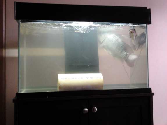 Then, a
bacterial bloom had started up in my tilapia aquarium which I hadn't
managed to change water fast enough to get ahead of. The days of the
trip were just too much. The water got too bad and one of the fish
died. That was the last straw on that. I set up a tiny 10 gallon
aquarium and moved the fish to it. With just a quart of water from the
first tank, the water tuned cloudy overnight! I think it all might have
something to do with chlorinated water, too, even tho I was putting
chlorine/chloramine removal drops in the water before adding it.
Then, a
bacterial bloom had started up in my tilapia aquarium which I hadn't
managed to change water fast enough to get ahead of. The days of the
trip were just too much. The water got too bad and one of the fish
died. That was the last straw on that. I set up a tiny 10 gallon
aquarium and moved the fish to it. With just a quart of water from the
first tank, the water tuned cloudy overnight! I think it all might have
something to do with chlorinated water, too, even tho I was putting
chlorine/chloramine removal drops in the water before adding it.
I set up a new 30 gallon aquarium that I had bought some
months previously when a pet store was going out of business. I dragged
water up the stairs from a rain barrel outside, bucket after bucket. It
has a great filter system and a faucet to drain water, which will be
much easier than siphoning it out. (But it won't clean the gravel.) And
a bright white or dim blue LED light. The two remaining fish finally
started perking up and hopefully eating again. And maybe I should
mention here that I left a cover off the pond outside and an otter (and
maybe raccoons) ate my 17 goldfish, which had grown from tiny to 4 or 5
inches long.
I'm not proving to be much of a fish farmer, and setting
up another aquaponics system is looking far off. Perhaps it's fortunate
that the tilapia haven't bred.
I set aside for next issue
a couple of 'idea' articles about floating hydro power and one about
wind power with a Tesla turbine, that I hadn't finished working out. I
had it about ready to go on the 8th, but when I got up from an evening
nap to finish up, there was water everywhere. My hot water tank had
sprung a leak after 19 years and 11 months of service, and of course
replacing it made itself top priority for another day. (Just a few more
months and it could have been somebody else's problem!) Usually they
last less than 10 years. I attribute its longevity to buying a better
than base level tank in 1996 and to having the hot water at 130°F
or less instead of the scalding 140°F most people have it at, which
would surely reduce the rate of corrosion.
Congratulations to the Americans on their election! Of the
available choices I think it was a good decision. The rampant
corruption within all the ruling structures including the
blatant propaganda news media, who all staked everything on Mrs.
Clinton winning when Trump won the Republican nomination, just might
take some sort of hit. While the "oligarchy", "corporatocracy" or
"shadow government" can be expected to spare no effort or expense to
hamper and discredit him from behind the scenes via the media
(hopefully further
discrediting themselves in the process), Mr. Trump certainly won't
start world war three or end democracy, which were potentially in the
cards. Whatever Clinton supporters feel, there are certainly some
nations breathing a huge sigh of relief and seeing a new light shine in
a bleak landscape.
Of course, no election result changes the fact that our
democratic forms are all very primitive and badly need to evolve to
forms that are suitable for increasingly enlightened people with so
many capable of contributing so much, in an age of advancing
communications and growing interconnectedness. We are gradually better
learning how this might look, and I will soon be posting another update
to http://www.HandsOnDemocracy.org .
Differential Torque Converter: Gear Cutting
Having conceived it and seeing it seemed the most
suitable, I decided to go with the "Asymmetric" Differential unit I
mentioned last month. On the 8th I got the rotary table and dividing
plates for gear cutting. Much of the physical project work I managed to
do in October was setting up the equipment and jigs, and cutting gear
teeth and sample gears for the asymmetric differential unit that is to
be a main component of the torque converter.
Perhaps I chose too large a tooth size, because the
smallest gears are pretty large in diameter. That forced me to shrink
the center gears and to have only 4 pairs of outer gears. I'm no longer
confident that plastic ones will be sufficiently strong at the smaller
diameters with fewer sets of teeth taking the loads. It looks like
it'll have a mix of UHMW plastic spurs and larger steel center gears,
but still, meshing against each other with low friction and no need for
lubrication.
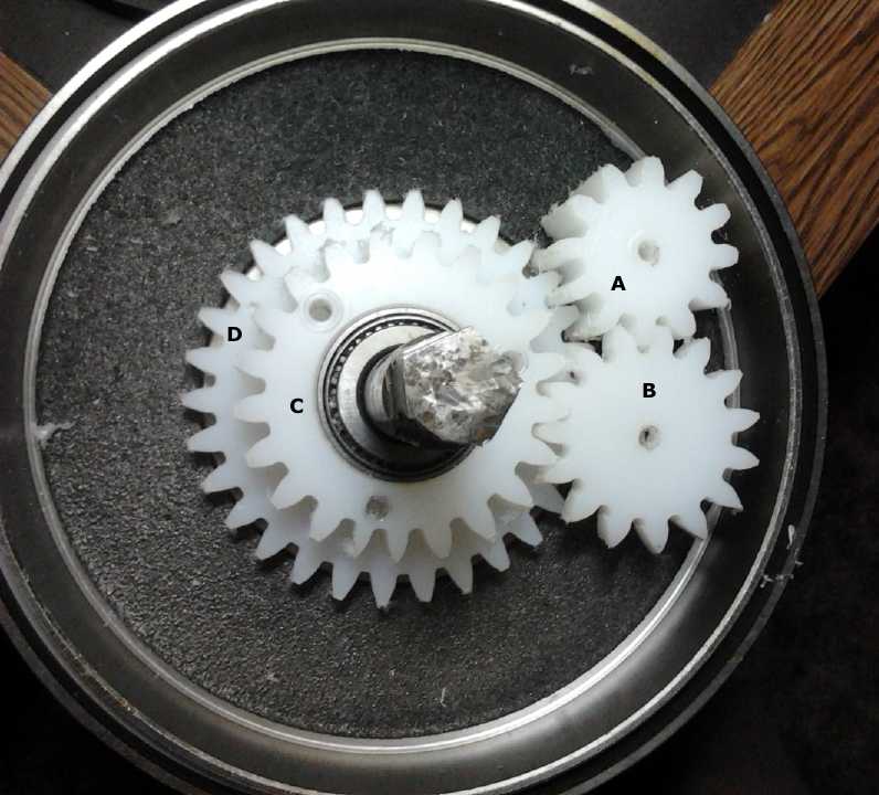 "C" is to be connected to the front,
and "D" to the rear, side shafts of the differential.
"C" is to be connected to the front,
and "D" to the rear, side shafts of the differential.
The whole (brake drum) case, with an opposite side cover plate (yet to
be made), is the center element.
'Spur' or 'planet' gear "A" is double width and meshes with "D" and "B".
"C" is just enough smaller that "A" doesn't touch it.
"B" is the direction reversing connection gear between "A" and "C". It
is beside "D" and its shaft is outside from it.
"A" and "B" are to spin freely on metal shafts running across between
the two sides.
There are to be 4 pairs of "A" and "B" gears around the outside to
reduce the loading per gear tooth.
I also found poly-V-belt pulleys at Mac's Auto Electric,
to use on the motor shaft with two of the same poly-V-belts as the one
I've had all along, which will turn the rough outside rim of the 10"
differential drum, used as 'flat belts' at that end. With the single
variable pulley on a swinging arm with a fixed pulley on the same
shaft, running to large pulleys on the motor shaft and on the
differential input end, the main components are pretty much picked out,
leaving lots of little details about shafts, bearings and shaft
fittings, and the chassis to hold them all together while allowing for
all required belt tension adjustments.
Various further details are of course to be found in the In
Depth
Project
Reports - Electric Transport.
The Electric Suzuki Swift
 On about the
13th a friend offered me an electric Suzuki
Swift, without batteries. It had been converted some years ago by
university mechanical engineering students under the tutelage of Randy
Holmquist of Canadian Electric Vehicles. It hadn't been on the street
since 2013, when the owner got a Mitsubishi iMiEV. This particular
vehicle had exceptional driving range, 65-75 Km, with just 9.6
KWH of batteries: 96V, 100AH. This is much farther than the Mazda
RX7-EV went, and with only 3/4 of the battery storage capacity. It was
of course a great asset that they were all lithiums rather than
lead-acid.
On about the
13th a friend offered me an electric Suzuki
Swift, without batteries. It had been converted some years ago by
university mechanical engineering students under the tutelage of Randy
Holmquist of Canadian Electric Vehicles. It hadn't been on the street
since 2013, when the owner got a Mitsubishi iMiEV. This particular
vehicle had exceptional driving range, 65-75 Km, with just 9.6
KWH of batteries: 96V, 100AH. This is much farther than the Mazda
RX7-EV went, and with only 3/4 of the battery storage capacity. It was
of course a great asset that they were all lithiums rather than
lead-acid.
Knowing what the owner had said about the car back when he
was driving it (as best I recall), it only used 120-140WH/Km
instead of the RX7's 170-200. Yet the owner lived in the country and it
was
around 50Km to and from town plus whatever driving he did in town, so
that range, plenty for most of my driving, was marginal for him. Hence
he purchased the
iMiEV with enough additional range to make the difference. But he also
complained about heavy steering, 'spongy' brakes, and that if one
accelerated too fast for very long, drawing over 350 amps, the motor
controller didn't like it and started a loud beeping.
After doing the paperwork, he drove it to my house and I
drove him home. The 25Km from Metchosin to my place used about 33% of
the range, according to a "% left" meter. It was well equipped with
meters -
except for the one I consider most informative as to state of charge, a
voltmeter. There was even one of those, a multiple meter of some sort,
but it hadn't been installed (yet). He
left me the batteries for the time being, so I can compare it with
before and after changing them. Personally I thought the steering was
fine. As a front wheel drive it was much lighter than the rear wheel
drive RX7. But then, I rarely drive a vehicle with power steering. The
brakes had no vacuum assist, and they did take much more push
than one expects or desires. Nevertheless, pushing hard enough does
make
tires skid. When I drove it accelerating up a hill I was favorably
impressed with the power - for a few seconds until the controller
started beeping. But the batteries as well as the controller are
probably stressed by supplying
that much current. I backed off a bit (ampmeter then read 200) and
after a few more seconds it stopped.
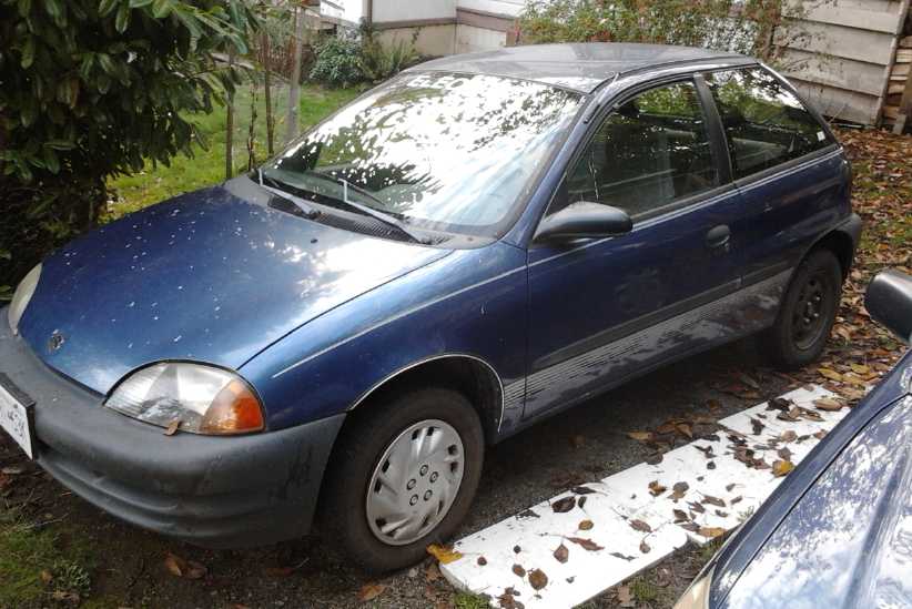
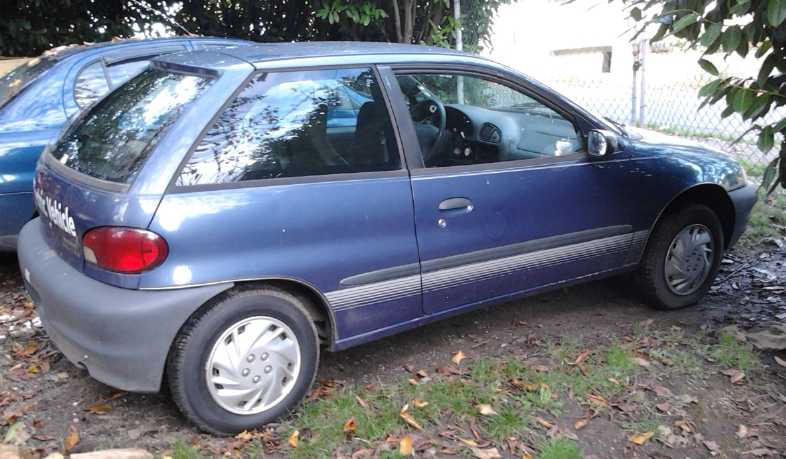 1998(?) Suzuki Swift.
In 2010 (just 6 years ago!) there were very few electric cars on the
road,
and those who converted it were justly proud to paint "Electric
Vehicle" on the back.
I could put in my 11
lithium cells (36v), which were
apparently the same as the 30 being removed, and 5 NiMH batteries, each
12v, 100AH for the other 60 volts, making up the 96 volts at the same
theoretical capacity. They certainly weren't going to fit in the
battery box that had been welded together under the back seat for 30
compact lithium cells. I figured I could sacrifice the bottom of the
small rear cargo space, or 1/2 the back seat.
Toward the end of the month I bought several 12 volt
battery chargers for the NiMH batteries. In the meantime I was doing
nearly all my driving in it with the original batteries and getting a
good feel for it. It seemed to be using around 135-150 WH/Km, about 'as
advertised', and that in cooler fall weather.
Regen Braking
Like the Miles electric truck, this vehicle has an AC
induction motor and regenerative
braking, engaged simply by lifting one's foot on the 'gas' pedal. (They
don't have the torque of the RX7's DC motor from a
stop, but it picks up quickly once it gets moving.) There being an
ampmeter, again I note that the amps being
returned by the braking are far less than those being put in during
acceleration. I checked it on a hill. The downhill test (both tries!)
was shortened or distorted by someone pulling out right in front of me.
Anyway I got that going up at 50 Km/H took around 200 amps. Going back
down at 50 Km/H seemed to return only around 40 amps in the brief times
I was able to maintain that constant speed. When I noted the large
difference before, some interpreted my remarks as indicating that I
didn't think regen braking was worthwhile or useful. Not at all. What I
was pointing out was that to get those very different figures between
acceleration and similar deceleration showed
how many losses there were through a car's drive train: through the
usually lossy automotive transmission, the differential, the wheel
bearings, and the tires on the road. Plus wind resistance and any
electrical losses within the motor and controller. If one calls it 200
amps and (being generous) 50, the middle would be 100 amps, suggesting
a 50% loss of the power applied and 50% loss of the power returned. The
actual figures thus give us a rough idea of how much room there seems
to be for improvement in vehicle efficiency - even for electric
vehicles. (The Mitsubishi iMiEV is reputed to have exceptionally
effective regen braking. Perhaps it simply has lower drivetrain losses.)
Perhaps it's also
worth noting that radial ply tires, which decades ago became an almost
universal standard, have about 10% less rolling resistance than the
bias ply tires that were previously the norm. The difference between
power applied and regen regained, as well as the total power needed to
drive, would only be worse if we still used bias ply tires. We also
know
that tires with low air pressure have noticeably higher rolling
friction than well inflated tires. This suggests that the most
significant areas to focus on improving are the transmission (as I've
been doing) and probably, still, the tires. (Think how easily a rail
car with almost frictionless steel wheels rolls compared to a car with
rubber tires.)
Mea culpa!... I got a good demo of the effect of tire
inflation. On November 7th I finally went to inflate the air suspension
units on the back of the Swift, added because of the battery weight.
They were completely flat and I put in 25 PSI. Then I thought to check
the tires. Three of them were down around 15 PSI. (The other had gone
completely flat recently and had been replaced by the previous owner.)
I pumped them all up to over 35 PSI. Now I'm not sure if the ride is
softer with the suspension inflated or harder with the tires inflated.
But it takes palpably less power to accelerate and more energy is
returned (or it slows less quickly) with regen braking. Sure enough, in
considerable driving around town on November 9th related to the hot
water heater, the Swift only used 120 WH/Km. That's excellent economy
and perhaps a 15% improvement over having 3 low tires!
Motor and controller efficiency also plays a roll. Even an
88% peak efficiency induction motor is also 12% minimum losses, so the
Electric Hubcap motor at perhaps 95% peak efficiency is some modest
improvement.
Compared with "Ultra Efficient" Ideals
My 'ideal' target for an "ultra efficient" drive system
has been 100 WH/Km. Realistically, while my Sprint is still small and
light, it's the somewhat larger 4-door version of the same car design
as the Swift, and perhaps I won't improve much on what the
2-door Swift
already does. At least, perhaps not without one of those new "permanent
magnet
assisted" or "electro-permanent magnet" motors that apparently can give
seemingly miraculous performance. (Another sidetracked project, but one
can only do so much at a time!) Still there's that reputed 30% loss in
automotive transmissions, that might favorably surprise us if
eliminated.
Even counting that, I'm guessing that for general
driving around town, I'll probably want two Electric Hubcap motors
rather than one for acceptable (and still not powerful) performance.
People said one wouldn't be enough power. I reserved my judgment, but
it looks like they must be right. On the prairies with flat ground one
just might do it, but here
one is always going up and down hills. Or if there was no gasoline
available (or it costs too much) and nobody cares if a car is sluggish
as long as it runs, one
might do.
For those interested in such details, here's my take on
"power
required" based mainly on seeing the ampmeter in the Swift and knowing
it's 96 volts, and that hence, about 100 amps means it's using 9.6 Kw -
about 13 horsepower. The "ultra efficient" case figures in the table
below would be for a car the same size and weight, assuming an "ideal"
30% higher transmission/drivetrain efficiency.
Power Required
|
Swift: Amps = KW, HP
|
Ultra-efficient Ideal: 30% more
efficiency - KW, HP
|
Constant speed driving, Downhill Grades
|
0-50 = 0-4800, 0-6
|
0-3360, 0-4.5
|
Lighter Acceleration, Uphill Grades
|
100 = 9600, 13
|
6720, 9
|
Stronger Acceleration, Steep Hills
|
200 = 19200, 26
|
13440, 18 (2 Electric Hubcaps)
|
Very strong Acceleration
|
300 = 28800, 38
|
out of reach - (3 E.H. motors?)
|
Moderately Strong Regen Braking
|
0- -50 = 0- -4800, 0- -6
|
0- -4800, 0- -6
|
In the regen braking case, I used typical figures for the
Swift, then considered that lower transmission losses for the 'ultra
efficient' means more power is returned in order to attain similar
braking effect, making the regen braking more effective compared to the
figures for thrust.
(The table was based on Swift figures as seen with low
tire inflation. When they were properly inflated, currents & power
went down perhaps 15%, and the regen similarly went up. So "Lighter
aceleration, Uphill grades" might now translate to "Moderate
acceleration, Moderate hills". Etcetera.)
Big Oil is on its way Out
A new article on RT.com said that analysts at BHP
Billiton (whoever they are) said that 2017 will be the year the
electric car revolution really gets started. In 2016 550,000 electric
cars were sold - no longer trivial numbers, and in Japan there are now
more charging stations than gas stations. The number of EV.s on the
road has risen sixfold even since 2014. What a change that is from 2008
when I started on trying to make a motor to add onto a car wheel, or
even since 2010 or 2011! Then, the only electric cars were
home-converted gas cars, and there was no such thing as a dedicated car
charging station.
But the International Energy Agency (IEA) said that
electric cars won't make much difference to oil consumption or stop it
from rising - that most of it is consumed by ships, planes, trains and
trucks. I think he's simply trying to downplay the significance. Also
BYD is now making electric freight trucks, and we could easily
electrify the railroads. With electrified railroads, cross-country
freight wil be so cheap and fast that people won't want to ship larger
items by air, and the reduction in air cargo will further curtail the
air freight service. And there are even small electric (manned)
aircraft, and electric boats that run straight off solar panels, which
have the potential to go bigger.
And this is disregarding technology advances and
innovations which will doubtless occur. Even years ago there was a
"sail assisted" freighter ship, which not only used less petroleum, but
was nicer to be on because the sails damped out most of the usual
rolling motions caused by waves.
Personal Doings & 'Business' Trip
My personal big news for October is that I
made up my mind to sell my house and move to Tlell on Graham Island in
Haida Gwaii. With the "housing bubble" in
Victoria, I should be able to sell my house for an exceptional price.
The
second property I had looked at in Haida Gwaii just up the road from
the first, was very economical at 180,000$, with a cabin having rental
income. It had a 12'x18' outbuilding that might make a decent shop, but
I hope to build a bigger one.
On the sensible advice of everyone, I went up to Haida
Gwaii on
October 31st, and flew back on November 3rd. (Hence the late
newsletter) I could see from the air that in contrast to most of the
mountainous west coast, much of the island was flat and even boggy. It
seemed like a cross between Alberta prairie and the less populous
Vancouver Island of decades ago. I think it will thrive in the future,
and also pass through troubled financial and economic times relatively
undisturbed.
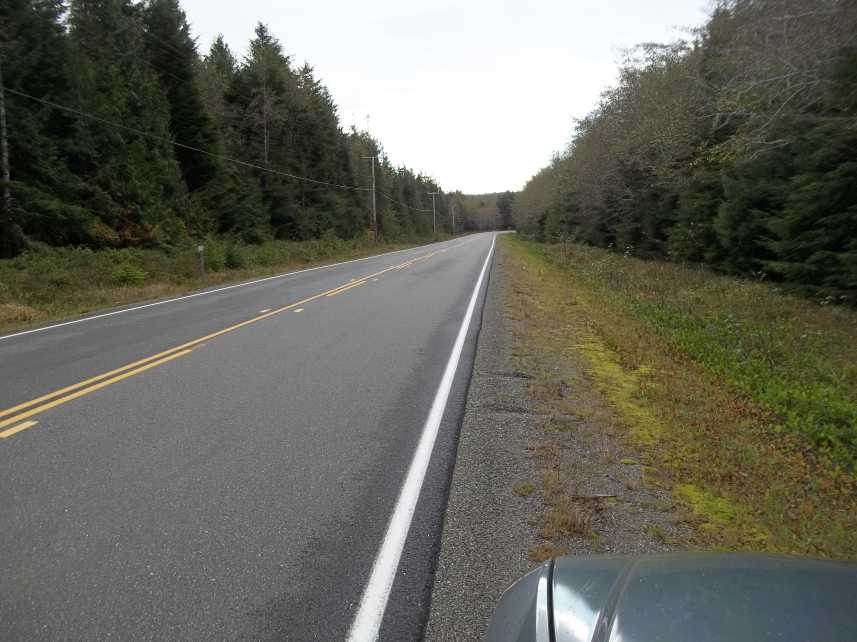 A typical section of highway from Masset to
Port Clements, October 31 2016.
A typical section of highway from Masset to
Port Clements, October 31 2016.
Between Masset and Tlell I met no traffic going my way and passed only
about 10 vehicles going the other way.
I decided I didn't especially like the layout of this
property. That realization alone of course made the 1500$ trip worth
while. There was a third prospect just two places over - south of the Crow's
Nest
Country
Store and Cafe instead of north of it: a
large but dumpy looking house on 15 acres of mixed clearing and forest.
I thought there must be something wrong with the house for the price of
220,000$, that perhaps it was rotting into the ground. The real estate
ad images betrayed no hint that it might have much value. But in fact
it had solid
looking concrete foundation walls. We (the owner of the first place
accompanied me)
found the door unlocked and walked through it, and (tho without being
able to inspect underneath) it seemed perfectly sound and solid. It
seemed like the opposite of most houses where a great looking paint job
distracts the viewer from noticing many problems: it seemed it really
only (and badly) needed
some painting, staining and varnishing, and some cracked windows
replaced, to be very nice. Soon she said what I had just started
thinking myself: "I think this might be better for your purposes than
my property."
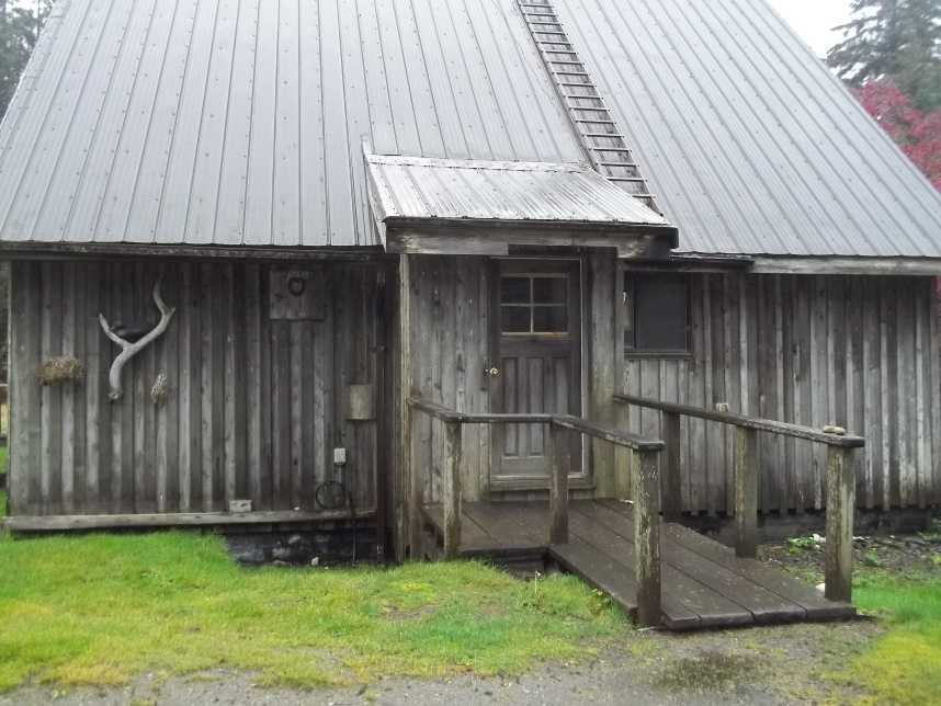 House in Tlell.
I had a different impression on actually seeing it than I did from the
pictures: As far as I could tell it seems
basically quite sound and up to modern standards, and has some nice
features and almost 2000 square feet.
Obvious problems were ugly (IMHO), dark paint colors inside, virtually
vanished paint or
stain outside, missing eavestroughs and cracked windows. These aren't
major work to fix.
The big question is: can I buy it? The
owner, after (he said) 12 years trying to sell it, was just in the
process of signing an agreement with a buyer. After all that time, was
I
just weeks or even days too late? If so, I'm deeply
disappointed, having thought I had found pretty much just what I wanted
at a price I could afford, and I'll have to keep looking, because I'm
still going to sell my house while the prices here are so high. It
makes financial sense "looking toward retirement" if that term still
applies in a collapsing economy where there are getting to be more
people in the "retired" age groups than in prime working ages.
In addition to that, I toured Graham Island pretty much
from one end of the road to the other, from Masset and the north
beaches to Queen Charlotte city (small town) in the south, and peered
down Skidegate channel. Without changing my general view of how to
proceed, I noticed there were more little stores and services here and
there than
I had feared.
My last dinner there was by prearrangement with the owner
of the property I'd gone up to look at, and the main course consisted
entirely of local food. It turned out she knew my sister in law! And
the freezer at the DIY B & B I stayed at was stuffed with salmon.
In spite of cost my plan is to ship almost everything I
have up there
including most of the tools, equipment and pieces for all my projects,
since not too much beyond basic living
and building supplies is available locally
and everything will cost plenty to buy there or to ship in if purchased
later.
There's still the possibility of sneaking a wire under the highway and
doing ocean wave power if I get some funding for that. I plan to take
the
electric vehicles up there. They couldn't be driven up along many
hundreds of miles of highway, but they have enough range to go between
towns on Haida Gwaii and will be especially valuable up there.
(Gasoline was 1.52 $/liter where I filled up.)
Tidal Flow - and River Flow - Power in Haida Gwaii
I read in the news that someone is doing a "tidal
power" experiment somewhere up there. A floating paddlewheel type unit
is
supposed to pump water up into a reservoir, and a regular sort of
hydroelectric turbine is to use the water to make electricity. The
floating paddlewheel itself is a good idea because it simply floats up
and down with the tides, maintaining the wheel's optimal depth. But the
overall plan
seems complicated and costly for attaining the desired result.
It really requires three separate projects: - the paddlewheel unit in
flowing
water, perhaps in the channel into Masset inlet, a large artificial
reservoir for sea water at some good elevation, and a hydroelectric
plant.
Their unit could be substantially more effective at
capturing the flow of water, too. The squareish, flat paddles are a
poor
shape: I'll have an article next month in the Electricity Generating
section about a 'venetian blind slats' curved 'wing' shape of blades on
a paddlewheel unit. (And since thinking up this "original" idea, I've
seen a couple of wheels with that shape of blades in videos on Youtube
on November 7th.) When I visited
Port Clements, I actually saw this unit tied up at the wharf. I can't
help but
think all those elaborate water pump fittings visible at the sides of
the wheel must have cost far more, and were far harder to make and
install, than a generator. (They probably pump more water than the
simple "pipe coil" pump units on Youtube, but those could simply be
multiplied at low cost to pump more.) And the vessel seemed to be much
larger and more elaborate than it needed to be for its simple purpose.
I suspect they would have changed a things substantially if they had
done some on-line research before building.
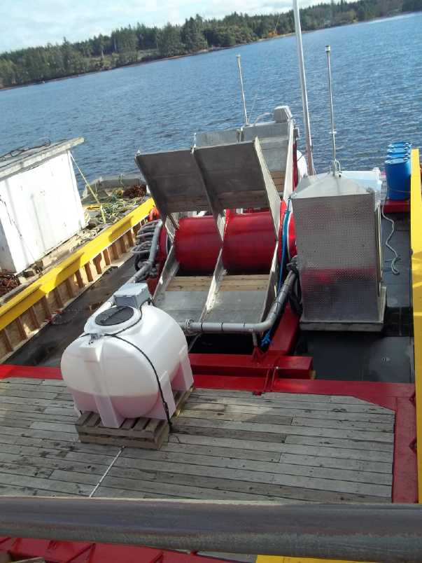 Tidal Flow Power Unit at Port Clements wharf.
The paddle wheel is about 6 feet wide.
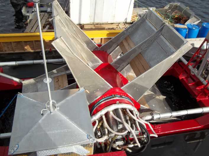
Another view.
Note the many elaborate connections in the water pumping system,
apparently duplicated on both ends.
It would be far more practical in my view - and I have
lately been considering such a
project (more details next month) - to start much smaller, and to have
multiple paddlewheel units each turning a generator
directly - along the lines of the successful (if crude looking) Zambezi
River project shown on Youtube and mentioned in TE News a month or two
back. Such units in tidal flows
would each of course provide intermittent power, nothing being
available
when the tidal flows are slack. However, in addition to Masset inlet
fed through a long, narrow channel off the north coast, there's the
narrow Skidegate channel between
Graham and Moresby islands on the south coast. Without having
studied the tide charts, I suspected there was at least an hour
difference
between the tidal flows. Someone up there told me it was several hours.
Perfect! When one current was slack the other would be streaming away.
One hitch is that there are no power lines connecting the northern and
southern halves of the island. But there are tall poles there, with
only
telephone cables half way up, all ready to wire up power lines to at
the top.
Looking at the terrain on Google Earth on November 7th, I
spotted a considerable inlet off the south of Masset inlet, fed by two
very narrow channels. It was plainly visible in the image that water
was just ripping through one of them in a very fast tidal flow. The
energy is thus much more concentrated than in the broad channel into
Masset inlet. It wasn't named on this map, but I'll call it the
"Justkatla Inlet" and "Juskatla Narrows" in honor of the only thing
nearby showing a name and having a road to it. Making several floating
power units to harness this energy could be a community project that
might potentially even supply power to the whole island when the tides
run - probably well over 1/2 the time. (A private project wouldn't be
feasible because a couple of kilometers of power line will be required
to send out the electricity.)
Even in addition to tidal flows, there are many small
rivers
on Graham Island, draining a lot of interior wetlands. The very same
(smaller size) paddlewheel units could be moored in rivers, which would
provide continuous flow.
Unfortunately for that idea, the flows seem to be pretty leisurely in
most
areas. It would be a question of finding fairly deep but rapidly
flowing points, close to existing power connections.
Again I think that on the small scale, using BC Hydro's
"net metering" program and selling power from small installations, with
approval and co-operation from the community and riverfront property
owners, would be the way to get it started. Juskatla would come after
experience gained with the smaller installations.
Building Renewable Energy Mechanisms Workshop/Lecture
Series
I met with the owner of Haida Gwaii Trader magazine
(HaidaGwaiiTrader.com), just after seeing the tidal flow machine at the
wharf and thinking how awkward parts of their plan and design looked. I
told her I
had been doing electric transport and sustainable energy projects for 8
years, and that I could have had a couple of suggestions for the tidal
flow power
project.
She told me that despite often favorable wind speeds, the
island community had rejected doing wind power. But, I asked, what had
they rejected?... Of course what they didn't want was big propellers
going whoop, whoop, whoop, making an unpleasant environment, unsafe for
birds and giving people headaches from their low frequency sonic or
subsonic effects. I said there were other ways to do wind power, and
that I had a couple of VAWT designs including one with a Tesla turbine
that had no external spinning parts (more details on that next issue).
I did very much like hearing again that there is
an island community, making decisions of that nature for itself,
instead of having them imposed by some somewhat 'out of touch' 'higher'
level of government centered elsewhere. It's easier to achieve in
isolated areas with small populations, but this is what needs more
development for social sustainability in communities around the world.
Back to making electricity... I thought that what was
really needed now was less theory (not of course
to belittle theories, calculations and new ideas!) and more building
and
installing of working projects.
Somewhere in all those thoughts and about the time of the
meeting, I got the idea,
with all my experience at building green energy devices (whether
successful or
not!), to give a series of workshop-lectures on how to
actually design and put together working equipment. I would cover
generators and turbines and their construction, and ideas for various
wind and water electrical generating products and potential practical
construction techniques.
But also I would cover the mechanical details of shafts,
keys, bearings, fittings, chassies and so on, and what all the various
options are for various types of fittings, and what all the little
parts are called, how they fit together, and where to buy or order
them. And importantly, I would talk about means for connecting smaller
electrical sources
to the power grid via the "net metering" program with induction
motor-generators and grid-tie inverters.
Those are the things that most people trying to start their great
little green
energy project know little to nothing about - as I didn't when I was
starting out in 2008. All the lectures would be done with samples and
examples of the devices and components being talked about, for people
to touch and fit together for themselves. Essentially, the series would
be piles of the more useful stuff from all the issues of TE
News, all concentrated into one set of lecture-workshops.
If I do that, and capture imaginations (which must surely
already
be fired up for people to want to attend), there might soon be many
green energy generation projects built than I could ever get working
myself. I might try in Victoria, but I'm also sure there must be eager
students in Haida Gwaii. In Haida Gwaii, I have good hope that
fortuitously situated property owners and the community would be happy
to be involved
with the green energy builders, and that builders would get together,
so that power projects could be joint ventures sanctioned by the
community instead of one person
needing to have everything including all the requisite tools and
the target energy source, and to build everything himself. And I would
like also to discuss with participants, ideas for how to equitably
split electricity revenues between land owners, the builders, and
anyone who invests money into the projects. But
anywhere, useful things would be likely to be built following the
lectures.
Gosh, maybe someone could record the lectures and they
could go up on youtube and a web site. Wouldn't that spread these
essential knowledge
tidbits quickly? No longer would one have to 'be where the action is'
to uncover the 'industry secrets', or really industry specialized
knowledge. They'd be up there for all!
In Passing
(Miscellaneous topics, editorial comments & opinionated rants)
Evolution of Democracy
A constitution may perhaps be a marvelous document. But
while the American constitution was a radical and progressive document
when it was written, the founding fathers could never have imagined the
world as it is today, nor would we fit happily into their world. In 240
years, most everything has changed. The world is always changing and
adapting - evolving. The fathers were happy to have created a way to
change governments without death of a monarch or a revolution. They
didn't consider that needs are ever changing and so failed to put
provision for evolution into it. It gradually became ossified and
obsolete, and for a long time now has not been well serving the public
good. Without consideration of the core values in decision making,
"social creep" gradually allowed, then fostered, narrow predatory
interests to come into positions of social, political and economic
dominance.
There are better ways of doing things. They just need to
be dreamed of and tried. In the town of Nelson, BC, Canada, the great
"status quo club" (or "oligarchy" or whatever name one chooses to call
it) pulled out
and left the town in economic ruin. A university, an art school, a mill
and other sustaining institutions were all shut down within a short
period - almost all at once. However, the workers at the lumber mill
purchased the mill and started to run it for themselves. I don't know
the exact arrangements, but without profits from the mill being sucked
away, the workers did better than ever before, spent much of their
money locally, and the town regained its economic health.
But this story is exceptional. Quite often, and especially
in the USA, when some new endeavor outside of the "status quo club"
prospers or threatens to become prosperous, it is usually attacked and
ruined by interference from the government that ought to be ensuring a
level playing field for all. The "American dream" is permitted only to
"oligarchy" members, and then only if they don't "make waves" and only
see the "bottom
line" as being monetary gains. For them, the government will do any
favors,
bend over backward to help - because so many of the same people who run
them also run the government. (I mentioned David Quintieri's video on
these conflicts of interest in a recent issue.)
There needs to be an intention first to evolve new
democratic forms and systems, and then in that evolution to put the
core values first.
Today with modern communication including the internet, it
is both practical and necessary to have means for citizens to have the
means for even daily communication with the elected, to make those
interested in an issue active participants in the decision making
process. Electing a representative every few years and expecting them
to act as desired on whatever issues may arise in our fast-paced modern
society is ludicrous.
The universal core values: Quality of Life, Growth, and
Equality; overlie many subsidiary values, which have often mistakenly
been put first as part of an ideology. There are underlying assumptions
when secondary values are promoted, for example when espousing that
socialism or capitalism is the "ism" to base society on... because,
implicitly, it is supposed that it will improve peoples' quality of
life, provide growth opportunities, and help attain toward equality.
But basing societal (and even family) decisions on
secondary values instead of directly and explicitly on the primary ones
results in a "social creep" away from the primary values as decisions
are made, one after another, over time. Adherence to any "ism" prevents
seeing clearly what is truly needed or best in each given situation,
for ongoing social sustainability. It gradually subverts progress and
social evolution and leads to eventual collapse, which has been the
final outcome of every civilization so far throughout history.
It need not be so. Social sustainability design teams can
explicitly consider: Does making this decision improve quality of life
for each person?, does it provide for growth?, and does it provide for
more equality? Society today is better equipped than ever before to
create socially sustainable families and communities, followed by
regions, nations and finally - when democratic systems have evolved in
accord with the core values, considered and administered in empathy,
compassion and love, to the point where it will be a blessing to all
mankind instead of a global tyranny - the world.
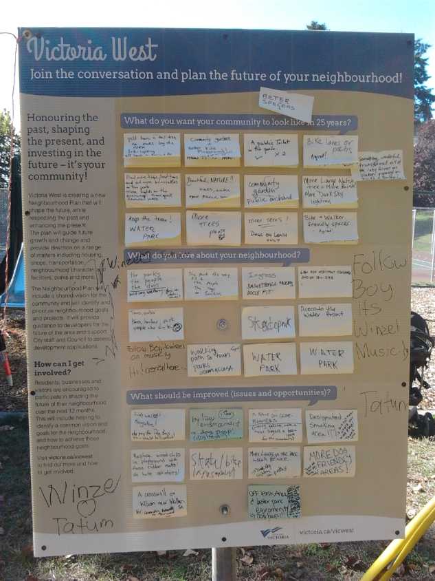
Here is an idea fom the City of Victoria BC for gethering
public input: a billboard with "post-it" notes for people to write
ideas on. I see merit in this, even while it is being abused by the
thoughtless and can't be considered any sort of complete solution.
Newsletters Index/Highlights: http://www.TurquoiseEnergy.com/news/index.html
Construction Manuals and information:
- Electric Hubcap Family Motors - Turquoise Motor Controllers
- Preliminary Ni-Mn, Ni-Ni Battery Making book
Products Catalog
(Will accept BITCOIN digital currency)
...all at: http://www.TurquoiseEnergy.com/
(orders: e-mail craig@saers.com)
Electric Hubcap Motor Systems - Electric Transport
'Hubcap'
motor, Chevy Sprint & Infinitely Variable Transmission
Differential Torque Converter in the Sprint?
Getting back to getting the Sprint going, I thought about
how a misaligned chain would jam up, and then again about the V-belts
that just slipped. I was pretty sure the V-belt pulley alignment wasn't
quite as critical as the chain sprocket alignment.
What if I put the so-called 12" (11.75" O.D.) V-belt
pulley, the largest one that would fit in the space, on the end of the
differential? That would need just 66% of the torque that the 7.75"
pulley needed, and it would have more surface gripping the belt. Also
it could be sanded to make the surface rougher, plus I now had the
wedge to keep the tension adjustment from slipping looser - factors
further increasing the grip. If I used the 5.75" pulley on the control
arm shaft, that would be about 2.04 to 1 reduction. Thus to get near
the 1.5 to 1 reduction idle point, the variable pulley section would
have to speed up instead of slow down, also reducing the torque it
would
have to handle.
The first thing to do if they would fit would be to try it
with two fixed pulleys on the two shafts, both larger than the ones I
had tried before. With the 11.75" pulley on the bottom, a 6.75" pulley,
if I could find one, would be ideal for the top, making a ratio of
1.74:1.
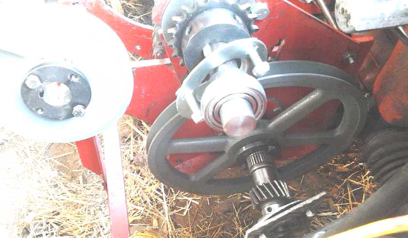 12" Pulley on Differential Left.
Oops, not enough space to the drive shaft for the other desired pulley.
Of the pulleys I had, the 5.75" would make too high a
"gear"
for low speed car motion (6 or 7 to 1), while the 7.75" one would be
awfully close to the 1.5:1 idle point (1.516). But the two shafts were
a little too close together to fit even the 5.75" with the 11.75". Did
I really want to go out and buy a 10" pulley and belt to try? All these
parts - pulleys, hubs and belts - just for experiments add up, and with
the store being somewhat distant, the shopping takes up time. The ratio
worked out nicely for a 'low gear', 1.7:1, which should make a final
drive of about 12:1, motor to wheel. But how much less torque did it
need than the 8" pulley? Might it just slip like the first one?
The next day I decided to buy them, but I got a pressed
metal pulley and 1" weld-on hub instead of a pulley to fit the "H"
taper-lock bushing that I had bored for the differential end shaft.
This was because I started thinking about the configuration with the
third shaft. If there was a 10" pulley on the motor shaft and a 12"
pulley on the differential, the third shaft could have two relatively
small pulleys (one variable) and spin much faster, without needing a
whole lot of torque.
However, this left the experiment in limbo. Either I
should have bought two pulleys to have one that uses "H" bushings for
the experiment (the costs add up!), or I would have to do some welding
and un-welding to have a 30mm center for the experiment and then
replace it with a 1" center for the motor shaft.
Then again, if I was to make the third shaft - the
reduction control shaft - it would have to be aligned 'perfectly' to
the differential anyway... so why not have the chain drive instead of
the
V-belt? But this could be done similarly, with a big sprocket on the
differential (minimizing the pull required to get sufficient torque)
and a small one on the third shaft, sized to match the big-small
variable pulley system coming from the motor. If I used a 72 tooth
sprocket on the differential instead of 36, the chain pulling radius
would be double and so the force on the chain would be cut in half. It
would have less tendency to jam.
There's room for that if there's a relatively small sprocket on the
control shaft.
Unlike on typical configurations of two-variable-pulley
drives there's no centrifugal clutch. I note here that it would
doubtless be hard to force the variable pulley halves apart by pushing
the third shaft away from the first, if the mechanism isn't turning. So
if it needs to be apart to get to "low gear" and get it turning, there
might be problems getting it started. But slacking off the pulley to
allow the halves to come together would cause slack in the belt. In
that case, either spontaneously or by trying to go, the belt would
surely pop out a bit and allow the spring to push the halves together
until there's belt tension again. So the "lowest gear", to get the car
moving, should be had with the pulley at its maximum diameter and the
control lever slack. The other way, just as good in theory, would
likely prove troublesome. Pulley sizes and configurations need to take
that into account.
Thinking about how and what to do was as far as I got.
Kelly BLDC Motor Controller Repair
When I had assembled and tested the Electric Caik
Outboard, I took it out to the Sprint car, disconnected a battery to
have 24 volts instead of 36, and hooked it up. When I had finally
figured out the correct phase connections (made more difficult since
the controller wasn't working right), I found there were still
rotational positions that the motor wouldn't start from. My fears were
confirmed: The Kelly BLDC motor controller must have some blown
drivers, the lows or the highs of one of the phases, and so only 4
positions in the rotation sequence of 6 were providing power. It wasn't
some additional unseen fault in the Electric Hubcap motor.
The next question was, could blown power mosfets simply be
replaced, or did the trouble extend back into the gate drive circuitry,
requiring sending it back to Kelly for more extensive repair or
replacement?
I disconnected and dismounted the controller and brought
it into the house. I opened it and saw (and smelled) the burned spot
where the magic smoke had escaped from. (Electronic devices don't work
if the magic smoke trapped inside the components escapes.) I looked
at all the screws that had to be removed just to get at the circuit
board, and the inaccessible screws sandwiched behind other plates to
remove the power transistors. This unit was definitely not designed and
made for serviceability. I didn't get any further in October.
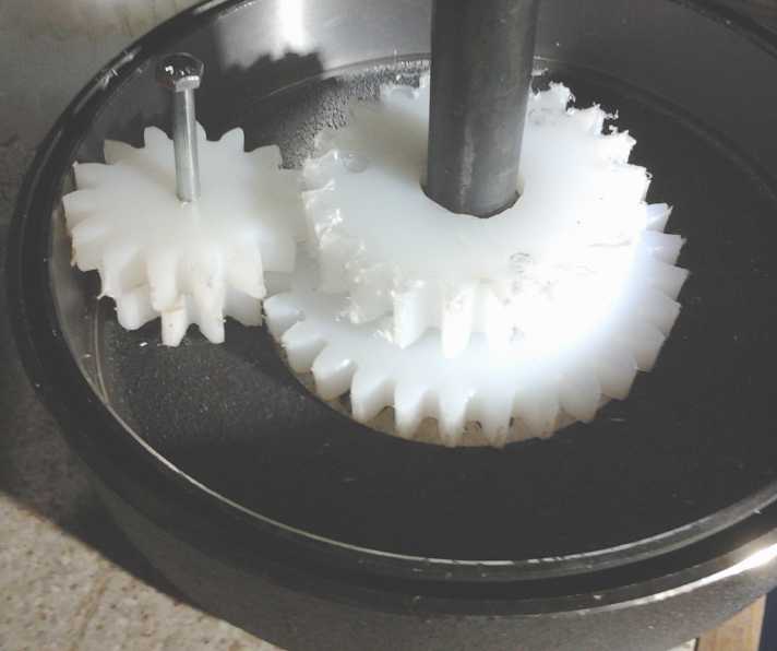
Asymmetric Differential with Spur Gears: Gears & Gear Cutting
On the 9th the rotary table and dividing heads arrived.
(Actually they said they had had them a week, but someone was on
holiday and they couldn't find the paperwork to call me.) After that,
gear making dominated the project work.
On the 12th I turned a sample gear to the diameter for 33
teeth. I used a disc of UHMW plastic that happened to have SDS mounting
holes drilled in it, and I went with that. I had already cut SDS
mounting holes in a plate for the lathe, so it was easy to mount it and
turn it. The rotary table also had 3 radial slots for mounting things,
so the "T" nuts could be moved in and out, 120° apart like the SDS.
"T" nuts usually have 5/16" or 3/8" threaded holes, but the SDS is
1/4", so I couldn't use regular "T" nuts. On the 13th I figured out I
could just use 3/4" wide steel bar pieces and pound them just a bit
wider so they fit exactly in the slots under the lips, and make 1/4"
threaded holes for the bolts. So the bolts went through the plastic,
through an SDS bushing (used as a spacer), and threaded into the holes
in the bars in the slots.
The rotary table was too big to mount directly on my
little milling machine in a position for the cutter in the chuck to cut
the gear teeth. I had a late nap and got up and made a plate to hold it
on the bed, then tried cutting the gear 33 tooth practice gear.
Somewhere I divided the depth by 2. I had just watched a video of a guy
using a dividing head, going about 1-1/2 turns between teeth. Mine was
a bit more than 1/2 a turn... but it should have been 2-1/2 turns, not
1-1/2. With the depth too small, and all the fuzz of plastic sticking
to everything, it didn't seem too bad until I had done quite a few -
15. Wait a minute, shouldn't I be 1/2 way around the gear by now, not
just over 1/4?
When I'd figured that out, I put the piece back on the
lathe and turned it down to the size for 30 teeth. Then I put it back
on the rotary table. This time TWO and a half turns per tooth!!! Well
of course that was wrong again, because that was angle for 33 teeth,
not 30. After just a few teeth this time I realized my mistake and went
into the kitchen for a cup of coffee. There I found the real problem:
the clock said 1 AM - midnight! (DST) I had no idea it had got so late.
I discovered years ago that when I worked too late at night computer
programming, in the morning I often returned and found I had made
numerous silly mistakes, and wondered what drugs I had been on. While
we may become "night owls", the brain nevertheless seems to lose focus
at night and one becomes something of a zombie on autopilot. I had only
planned to make the mounting plate, but I got excited about actually
being ready to do a gear. I should have checked the clock then, and I
certainly should have quit when I found I was doing the 33 teeth wrong.
By the evening of the 14th I had marked out out the 50
tooth gear and cut it on the bandsaw, drilled SDS holes in it, and
turned the outside smooth on the lathe. I then mounted it in the rotary
table and went to mill the teeth. There was no 50 - the dividing plates
went up to 49! And there was no 25 either: one plate went 21, 23, 27,
29. I would have to do it all manually without the plates.
360/50=7.2°. Let's see, that's 1-3/4 turns and another "12" little
marks on the crank wheel. Get any one wrong at any point, and the gear
was toast. I wrote down each of the 50 angles on a scrap of paper. I
thought the right cutting wheel was mounted, but I checked it to make
sure. I had to get mirror under it and then figure out the backwards
numbers. Nope, it was the "26 to 34" teeth wheel. (And why wouldn't it
be?) I put the right one on, "35 to fifty something".
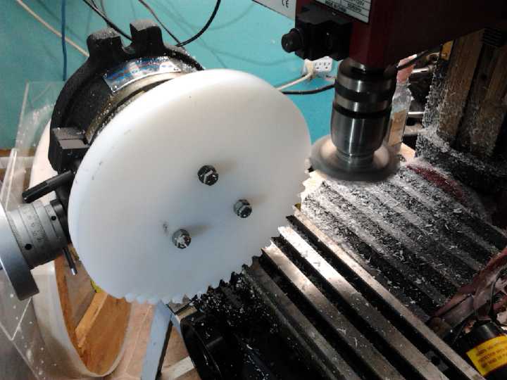 Milling gears
is both tedious and nerve racking,
winding the wheel around to exact positions and then cranking the table
"X" back and forth to move the gear through the cutter, but I did it
without any mistakes on this occasion. "Tool depth" was supposedly 9mm
(2.25*m4). I
measured about 8.75 and thought that would be okay. When I meshed it
with the practice gear (on which tooth depth had come out only about
8.25mm) they meshed smoothly, but the gear disk centers were 163mm
apart instead of 160 and could come no closer. (30+50 teeth)* m4 / 2 =
160. Even with the teeth 1/4mm shallow, theoretically it should have
been 161mm center to center. Perhaps it's that plastic
cuts a bit differently and not as smoothly as metal. Obviously if one
is precision cutting the chassis with axle and bearing holes spaced
exactly "X" distance and they need to be "X" + 3mm apart, that's going
to be trouble.
Milling gears
is both tedious and nerve racking,
winding the wheel around to exact positions and then cranking the table
"X" back and forth to move the gear through the cutter, but I did it
without any mistakes on this occasion. "Tool depth" was supposedly 9mm
(2.25*m4). I
measured about 8.75 and thought that would be okay. When I meshed it
with the practice gear (on which tooth depth had come out only about
8.25mm) they meshed smoothly, but the gear disk centers were 163mm
apart instead of 160 and could come no closer. (30+50 teeth)* m4 / 2 =
160. Even with the teeth 1/4mm shallow, theoretically it should have
been 161mm center to center. Perhaps it's that plastic
cuts a bit differently and not as smoothly as metal. Obviously if one
is precision cutting the chassis with axle and bearing holes spaced
exactly "X" distance and they need to be "X" + 3mm apart, that's going
to be trouble.
There was another problem.
I had bought another 2767R
brake drum to use as the housing, but I hadn't actually sized up the
drum to see how the gears would fit. When I set the 50 tooth gear in
the drum it was obvious there wasn't anything like enough room on the
outside of it for the peripheral 'planetary' gears - the 30 tooth
practice gear was a better fit!
On the 15th I thought, wait a minute! The calculations
with metric "m" gear cutters are amazingly simple. For the m4 size I
got, you just need to size up the drum in millimeters, subtract 8 to
account for
the outer margins, and divide by 4 to get the total number of teeth
that will fit. It doesn't seem to matter which gear has how many teeth
as
long as they add up. It was 228mm, so 220/4=55. The smallest number of
teeth one could put on a gear is 12: the #1 tooth cutting wheel says
"12-13" and they go up from there. A 12 tooth gear is 48+8=56mm in
diameter - over 2"! I had been thinking they would be considerably
smaller than that, not to say half, but m4 is pretty big gear teeth. So
55 teeth would be 12+31+12=55, allowing for 12 tooth planetaries on all
sides of the center gear. In order to have a bit of outside clearance,
it would in fact be exactly a 30 tooth gear in the middle.
I decided to cut a planetary. The "SDS" bushing was out,
as the cutter would hit the mounting screws even if they weren't past
the
outside edge already. I looked at the center hole of the rotary table
and
realized it was a #2 morse taper. I dug into my lathe tools box and
found something I had made for turning pieces that mounted on a 1"
keyed shaft. I drilled a hole in the end and threaded it for 1/4" x 20.
It wasn't ideal as it already had a 3/8" hole there, so the 1/4" hole
started inside the 3/8" one. But it did the job - or seemed to.
I drilled a 1/4" hole in a piece of UHMW-PE, then roughed
out the disk on the bandsaw. I turned it on the lathe to the right
diameter, then moved it to the rotary table and milling machine.
Unfortunately, the holding piece wasn't quite long enough and the
cutter would hit the rotary table if it cut all the way across. I
decided to just cut the gear, and maybe turn it around and re-cut to
get the last bit. The jig must have slipped a bit on each tooth or on
some of the teeth, because one tooth ended up somewhat wider than all
the rest. (And it would have been hard to miscalculate 30.0° tooth
angles!)
It seemed like a great way to do it, but it wasn't quite
there. I decided to make another similar morse taper shaft, but with a
longer body for the cutter to clear the rotary table and holes to the
sides for pins. The pins would stick into the plastic gears so they
couldn't rotate on the shaft and the teeth would be even.
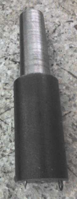
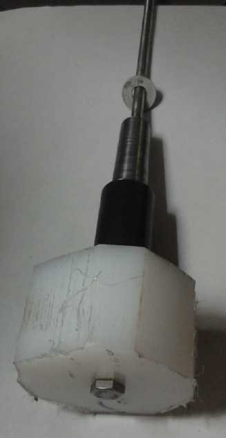 The new holder for small gears, both for the
lathe and the rotary table.
The new holder for small gears, both for the
lathe and the rotary table.
A nut and washer on the threaded rod ensures it doesn't come loose in
either device.
I checked out the fit in the drum. With the 30 tooth
practice gear in the middle, the 'planet' fit inside the outer rim in
any direction with about 2mm clearance as expected. (How about that!)
On the 19th I made a 27 tooth gear. It was the first
"perfect" gear, I thought, other than the teeth being about 9.4mm
instead of 9.0. Maybe I need one of those fancy digital position
readouts on the milling machine after all. Sigh! Later I noticed the
real problem: the disk hadn't been quite centered on the rotary table,
so the teeth were a bit deeper on one side and shallower opposite. They
averaged out to 9mm. Another refinement: on the lathe, when cutting the
outside circle, bore out the center to fit over the 1" shaft of the
same morse taper piece I was using for the small gears, to hold it
exactly centered. They have to be bored out some time for their shafts
anyway; I just hadn't bothered yet. Which was just as well, because
none
of the gears so far was usable...
I figured, each tooth smaller made the diameter 4mm
smaller. So a 27 tooth gear would be 12mm smaller diameter than a 30
tooth gear, and the teeth were 9mm deep, so the teeth of the smaller
gear would entirely clear those of the planetary of the larger. When it
was done I saw that they didn't. Duh! 12mm of diameter is only 6mm of
radius! It would have to be 25 teeth, 5 teeth and 10mm of radius less.
From 50 teeth down to 25, and now only 100mm effective diameter; 108 to
the outside. Tho they were still twice the diameter of typical metal
gears, this was starting to get pretty small in my estimation, when my
idea was to make very large plastic gears with low loading per surface
area owing to their size. I hadn't counted on the large m4 teeth making
for such a large minimum sized gear as to so much reduce the size of
the center gears. Perhaps I should consider steel gears for the two
not-so-large center ones. I wonder how much they might cost to buy...
versus how hard cutting steel teeth would be. The planetaries can still
be plastic so there are no steel gears meshing with steel gears, which
would require oil lubrication.
I started to think I should have bought m3 or smaller
tooth cutters. But then the smaller they are, the more there are to
cut, and this was tedious work! And, without really examining the
issue, I'm pretty sure bigger teeth are stronger and better for plastic.
On the other hand, as indicated in "Fixed Gear
Experiment?" below, maybe the thing to do is to keep the RPM up in the
transmission unit itself, even raising the output speed in the highest
ranges instead of lowering it, and then have a considerable final fixed
reduction before a car wheel drive. The gears and the belts would run
faster but with less pressure on them. Then they might be quite
adequate.
Up to this point I had been using 7/8" thick scrounged
plastic, but two of those wouldn't quite fit in the rim width. I could
do one that thickness, but at least one couldn't be more than 3/4" and
both 3/4" would be better. On the 19th all I got done was to buy a
small piece of plastic, 5/8" thick as they had no 3/4" handy, for a 30
tooth
gear and maybe a couple of planetaries. But really the 5/8" is probably
a better fit.
On the 20th and 21st I got a 25 tooth gear cut out and
lathed, with a 1" hole bored in the center, ready to cut the teeth. But
before cutting them, I wanted the 1" center axle described above, with
a #2 morse taper
that would fit in the rotary table and hold the gear for sure dead
center. I also wanted this to be the improved mounting piece for the
small spur/planetary gears, and I spent a couple of hours turning it
down to the taper and drilling and tapping both ends. I cut the gear
teeth on the 22nd. Then I drilled two holes in the 1" center near the
outside edge, cut two nails to fit, and put them in the holes with the
points sticking out. On this I mounted a 1.5" thick piece I had cut for
a wide 'planetary' to go across the main gears, turned it round, and
milled its 12 teeth. It was harder milling than the larger gears. Not
only was there a long distance, but the 12-13 tooth cutter seems to
take
extra power, and unless I cut very slowly the milling machine's motor
suddenly stalls and won't restart until it's turned off and on again.
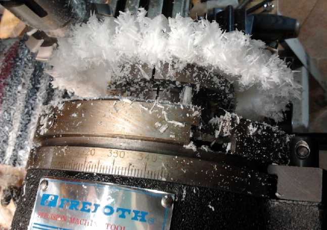
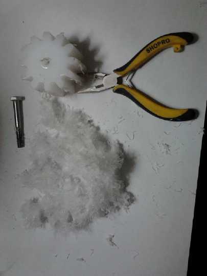 The best technique to rapidly remove
most of the plastic fur seemed to
be to pluck it off with a small pair of pliers.
The best technique to rapidly remove
most of the plastic fur seemed to
be to pluck it off with a small pair of pliers.
Another result of the large size of the spur/planet gears
was that when I sized everything up (now having cut enough gears, good
or bad, to do so) it became apparent that only 4 pairs could be fitted
around the rim, at 90° angles. Of course one turns gears until the
teeth line up to put them together. As I went to bed, it occurred to me
that if there were 4 sets of planetaries, on the same two large gears,
all of them had to line up at the same time. If some were 1/2 a tooth
offset from others that were in line, the whole thing wouldn't work.
And in order to have quadrilateral symmetry, the number of teeth of the
large gears had to differ by 0, 4, 8, 12, etc. 25 teeth is different
from 30 teeth by 5. I tried the spacings to make sure, but there wasn't
room for 5 sets of planetaries around the rim. (3 could potentially be
fitted in the 5 spaces by having one of the side gears on the other
side.) With 26 teeth would hit the teeth of the larger gear. Next down
is 22 teeth.
So we now have "big" gears that are much smaller than I
planned, only 5/8" thick, and meshing with only 4 sets of planetaries
instead of 6 or 8. The only thing still big and robust is the tooth
size - and the peripheral gears. Everything could be fitted, but to
make it all more as I had originally envisioned it, the drum would have
to be more like 12-15" in diameter instead of 10. That would lead to
other fitting problems. Or the gears would have to have much smaller
teeth, which in plastic I think would be less robust. (But I'm
beginning to think m3 might have been a better choice.) It became more
and more apparent that the "big" gears, smaller and smaller than what I
had envisioned, would need to be steel. That still doesn't make the
objectionable steel on steel meshing since the spurs/planetaries are
still plastic, so it's probably better than needing a very large size.
Cutting plastic gears seemed okay, but I didn't have much
confidence in doing steel. I decided to order them. The 30 tooth one
was simple. It would be 5/8" or maybe 11/16" wide with a 1" keyed
center hole for a 1" keyed shaft. The 22 tooth one had to be on
bearings and able to turn independently round the other, meaning its
shaft would be a sort of a pipe over the 1" shaft with a bearing at
each end. I hadn't yet figured out the inner and outer dimensions for
that.
 On the 27th I
tried to make a 22 tooth gear. Again the
calculations got more complicated. 360/22=16.363636 degrees/tooth. The
knob turns the table 4 degrees per turn, so that's 4 turns, leaving
.363636°. .363636*22=8. There wasn't a 22 indents setting on any of
the plates. 8/22=4/11. Nope, nothing less than 15 indents. But it's
also 12/33, and there was a 33 indents plate. So I set the divider to
traverse 12 holes per tooth. I neglected at this point to remember the
knob turns the table 4 degrees per turn, so I had 12/33 of 4 degrees
instead of 12/33 of one degree. It should instead have been 3 indents
forward per tooth. The gear came out with 21 teeth and uneven spacing
on the last 2 teeth, which I at least tried to even up by eye.
On the 27th I
tried to make a 22 tooth gear. Again the
calculations got more complicated. 360/22=16.363636 degrees/tooth. The
knob turns the table 4 degrees per turn, so that's 4 turns, leaving
.363636°. .363636*22=8. There wasn't a 22 indents setting on any of
the plates. 8/22=4/11. Nope, nothing less than 15 indents. But it's
also 12/33, and there was a 33 indents plate. So I set the divider to
traverse 12 holes per tooth. I neglected at this point to remember the
knob turns the table 4 degrees per turn, so I had 12/33 of 4 degrees
instead of 12/33 of one degree. It should instead have been 3 indents
forward per tooth. The gear came out with 21 teeth and uneven spacing
on the last 2 teeth, which I at least tried to even up by eye.
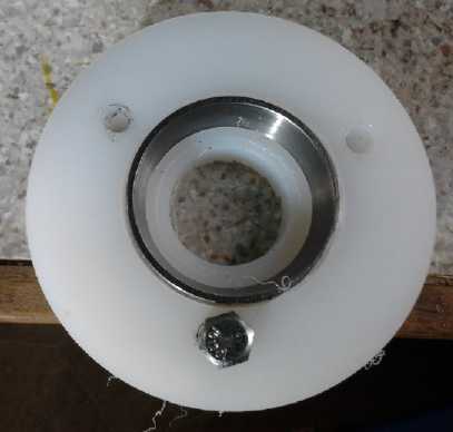
It did give me enough gears to start thinking about how
the bearings and shafts might fit together. I put in a center shaft and
a couple of bearings. That allowed it to actually turn the gears
against each other in the differential, if one held and turned the
small outer gears. I turned it to show someone how it all worked
together and he said it hurt his brain. (Well, I haven't seen this
combo anywhere before, so perhaps it's an invention within the overall
invention. It is thinner than a similarly constructed spur gear
differential as illustrated in Wikipedia. Maybe I'm some sort of
mechanical gear wizard after all? If a pretty amateur one.)
I then realized that even tho it was asymmetrical, if it
was used as a wheel differential, if the wheels were turning the same
speed, the gears inside would be motionless. I had been thinking they
would slowly turn, but that's not the case. (Not a mechanical wizard
after all.) What is different is that one wheel would doubtless have a
bit more driving force than the other, based on the difference in
center gear diameters.
"C" is to be connected to the front,
and "D" to the rear, side shafts of the differential.
The whole (brake drum) case, with an opposite side cover plate (yet to
be made), is the center element.
'Spur' or 'planet' gear "A" is double width and meshes with "D" and "B".
"C" is just enough smaller that "A" doesn't touch it.
"B" is the direction reversing connection gear between "A" and "C". It
is beside "D" and its shaft is outside from it.
"A" and "B" are to spin freely on metal shafts running across between
the two sides.
There are to be 4 pairs of "A" and "B" gears around the outside to
reduce the loading per gear tooth.
 Here is my alternative to the
asymmetric differential, what I called the "double sun planetary gear"
Here is my alternative to the
asymmetric differential, what I called the "double sun planetary gear"
in previous TE News issues. The overall diameter needs to be a bit
larger (or the gears a little smaller)
because it has to accommodate the larger spur gear of the two, now
needing a few more teeth and
both turning tied together on the same axle. In the other unit,
the larger spur gear's axle is a little
closer to the center.
A functional difference is that the differential has a reverse
direction
of rotation - If one of the two
ends is rotated with the center stationary, the other end turns the
other way. In this configuration
they both turn the same way, at different speeds. Another difference is
that up to 8 (7?) of the single
axle spurs could be fitted instead of just 4 pairs, halfing the load on
each plastic tooth.
Fixed Gear Experiment?
On the 20th I got the idea to make fixed ratio plastic
gears and
drive the Sprint car with them, just to try out actually using the
plastic gear idea in a car. I visualized a small spur gear on the motor
and a great big one on the differential, with the left wheel's drive
shaft hooked up again. If things ran smoothly and easily, I still
figured it would take at least 8 to 1 reduction to reliably move the
car. Since the smallest gear has 12 teeth, the big one would need
12*8=96 teeth.
But there were problems with that idea: First, it would be
a lot of work. The whole box would have to be disassembled and the gear
put in, not to mention reconnection of the left drive shaft. Then,
making the gears. Then, a 60 tooth gear is about all that will fit in
the transmission box, and also about the largest the present tooth
milling setup can handle without modification. That only gives 5 to 1
reduction, so it would need 2 stages of reduction, by mounting another
shaft and having 4 gears. That seemed unpalatable just for an
experiment.
Or perhaps I could mount it on the left of the
differential and put something in to jam the differential so it was
essentially directly driving the right wheel drive shaft. Outboard a
12" gear could be fitted. That could be up to 74 teeth - still only 6
to 1, so it would still need 2 stages of reduction. That seemed to be
beyond what I wanted to make just for an experiment.
On the other hand, a smaller final drive gear would give a
closer approximation of how the smaller transmission final gears I was
now making would fare if they directly drove a wheel. I have a feeling
that they'll fall apart and will have to be made metal. Unless they are
run at higher speeds and have a 3 or 4 to 1 reduction before the final
drive shafts. The whole unit can make a speed increase or at least no
decrease in its "highest gear", which would then be followed by that
fixed decrease. Yah, that's the ticket, yah! So that 60 tooth gear
might just be a good size to try out right on the differential, driven
by a 15 or 20 tooth gear. And if it can't be any larger in diameter, it
could be quite wide, even a couple of inches, if 7/8" teeth don't like
the load. I set the idea aside for and kept cutting gears for the new
differential.
Electric Caik Outboard Upgrade
On the 10th I finished reassembling the Electric
Caik Outboard with the upgraded rotor. To make sure it ran okay I
brought in the motor controller from the boat and tried it out. It ran
fine. Furthermore I checked out the cheap ampmeter with the modified
shunt sensor that I use in the boat, against the clamp-on DC ampmeter.
It read a few percent lower but close enough for general use. And I
don't actually know for sure which is off, or if the truth is somewhere
in the middle.
I do know that with 16 volts from a lithium battery it
took almost 30 amps to spin full speed in air - 2250 RPM. The high
current
surprised me at first... but then it was only only 16 volts (so 480
watts). At 24 volts it would have been only 20 amps. In TE News #61 I
measured that friction in the outboard leg accounts for over 2/3 of the
power consumed, so the motor itself probably took less than 150 watts -
an unsurprising 6.25 amps at 24 volts.
(And of course with the darned gearing down in the foot of the
outboard, the propeller was only going around 833 RPM.)
The 2250 RPM @16V figure also indicates that the 0-3000
RPM
Caik motor could be slightly over-revved to 3375 RPM at 24 volts - but
only out of the water. In the water the drag from the prop would surely
slow it below 3000.
When all seemed to work fine, I took it outside to test
the Kelly motor controller in the Sprint car - which was the original
reason for tackling the Outboard project at this time. I wouldn't have
done it just to test the controller, but of course I also wanted to at
last upgrade and reassemble the Caik Outboard -- and try it on the
water to see what it would do. Getting the 14' aluminum motorboat
moving faster would be nice. Getting it up on any sort of plane would
be fantastic!
(I also have this ongoing desire to build a 20' catamaran
to run with an electric outboard. It would glide effortlessly through
the water, and
could carry wave power buoys (and their anchors) between the hulls
for deployment in the ocean, or tidal/river flow power generators could
be carried or towed. Hulls would be polypropylene-epoxy on
polystyrene foam sandwich construction with a few strategic wooden
spars - strong and lightweight. - - - Easy there, easy!
Enough new projects already!)
Somehow I didn't get the boat into the water by the end of
the
month. Rats!
Electricity
Generation
Improved
750/1500 Watt Hugh Piggott Frictionless Axial Flux Alternator?
On September 28th, thinking I just might get access to a
small
moving stream, I started thinking about an alternator. It might make
more power than my recently converted car alternator would handle. Or I
might want to put more than one floating unit in the water, each with
its own alternator. It would be better to be set up to make alternators.
The large
diameter Piggott/Scorag axial flux air core layout with a resin cast
stator was great, but it was said to overheat with more than about 500
watts continuous load. I had had
the same trouble with the very first prototype Electric Hubcap motor.
In spite of making some ventilation holes, I could soon smell hot
polyester resin. Of course, I was putting a lot of power into it and
the RPM was quite low. There seemed to be two factors contributing to
the overheating at what is a pretty low power for the size.
The first factor is that the stators are cast as a solid
block of resin, 1/2" wide by about 14" diameter, with no ventilation.
This might be improved by ventilation holes near the wires and by
making the surface rough rather than smooth, just with sandpaper.
I could also consider the
"heat conductive" epoxy resin right around the coils, but it was sold
in small containers and cost too much for general application. I
wonder how they make it "heat conductive"? Is there something I easily
add
to regular epoxy resin?
The second factor was that there was no ventilation fan.
Granted it was being used in a windplant, but sitting with a flat face
to the wind, it wasn't designed to take advantage of that. The
magnets were cast into a solid disk of epoxy with a steel backing,
which would circulate the least amount of air while blocking air flow
near the stators.
The fix for that is exactly the way I've been doing motor
rotors: Wrap a popypropylene strap around each magnet and epoxy it in
place. The rotors would be easily done by CNC waterjet complete with
all holes and strapping slots. The magnets then act as centrifugal fan
blades. If cool air is permitted to enter near the center, it gets
flung outward to cool the stator coils. (assuming there is somewhere
for the warmed air to escape, of course - vent holes around the
outside.) I figure one could surely increase the power output by 50%
without overheating. It might even be double. That would mean 1000
watts instead of 500. But I'll stick with the more conservative figure,
making it 750 watts. That's one horsepower. (1HP = 746.7W)
A unique aspect to the Piggott design is having no iron
coil cores, which makes it frictionless and non-cogging. I discovered
in converting the car alternator to permanent magnet that even with no
cogging, there is some magnetic friction, which can only reduce the
efficiency. In a small windplant "frictionless" is especially important
because friction and or cogging will prevent the propeller from
starting to turn in light wind. And even if it turns it will need a
higher wind speed to reach a point where useful power is being
generated. For most any purpose where the driving force is
limited, frictionless is better - the ultimate in efficiency.
A 1500 watt unit would be made by doubling 750 watt
(formerly 500 watt) stators on
a single shaft. Instead of four rotors,
there would be a special center rotor common to both stators, so only
three would be needed. That would be cast in epoxy with polypropylene
or perhaps carbon fiber. (Awk! I'm getting itchy just thinking
about carbon fiber!) No steel plate would back it. It would be just the
width of the magnets, which would thus face both directions for the two
stators. It would have a steel center portion inside where the magnets
turn, and it might need a stainless steel (non-magnetic) ring around
the outside for strength. Depending how it was made, it might or might
not be an effective fan. If it was, the units could perhaps be expanded
to 3 or 4 stators and 2250 or 3000 watts. If not, two stators with one
cooling rotor for each would be the limit.
I am thinking about setting up for production. The 12"
diameter steel rotors would be a contract for Victoria Waterjet: The
same as my motor rotors fitted for an SDS taper-lock center bushing, 12
magnet strapping holes or slots, and vent holes near the center. (The
magnet strapping holes might be extended to fulfill the vent hole
role.) PP-epoxy end caps and outer rims would be similar to my earlier
Electric Hubcap motors and could probably use the same molds (assuming
I still have them), and the stators could have new UHMW molds, with the
O.D. sized to fit into and attach to the rims. I could use 1" shafts
and the same "trailer wheel" bearings and fittings as for the motors.
On November 10th, thinking about how wide bushings like
SDS or weld-on hubs are compared to the narrow axial flux alternators,
it occurred to me that I should put in holes in the rotors in positions
similar to car lug bolts, That way, the thin center rotor(s) of a
multi-stator, multi-rotor unit can be hung on threaded rods from the
outer "bearing" rotors. Otherwise the hubs will be fatter than the
space available. In addition, the rotors could optionally be mounted on
car or trailer wheel hubs per the Piggott windplant design. Two sets of
four holes in offset positions would allow mounting on a wheel hub and
adding threaded rod to extend it. Better more options than fewer!
I thought for a bit that if I sized the rotors right, I
could use 3 early motor cases now sitting around. But they're a bit
small in both directions, sized only for one 10" rotor and external
stator. Maybe I can use them up in special one-rotor small versions.
With my oldest 10" magnet rotor made from a brake disk for one of them.
They could have a bearing in the case and another external. Or is that
just a waste of time, wire and epoxy? It's said a rotor on each side of
the stator is needed to get good output at windplant propeller speeds,
and a 10" rotor already needs to turn faster than a 12", and allows
less room for coils. Well, with the existing parts, it's probably worth
one cludgy experiment.
http://www.TurquoiseEnergy.com
Victoria BC Canada