Turquoise
Energy Ltd. News #106
covering November 2016 (posted December 4th 2016)
Victoria BC
by Craig Carmichael
www.TurquoiseEnergy.com
= www.ElectricCaik.com
= www.ElectricHubcap.com
= www.ElectricWeel.com
Month In Brief
(Project Summaries)
- Project holdups - Improved Hugh Piggott 'frictionless' alternators -
Improved Tesla Air Turbine for wind power & OWC ocean wave power -
Water wheel blades, & (better) "Spiral Staircase" Underwater
Turbine idea, for energy capture from flowing water - Floats for
Floating Hydro Units - Setting up for another Sprint fixed ratio
differential transmission test - End of the Old e-Motorcycle Story
In Passing
(Miscellaneous topics, editorial comments & opinionated rants)
- Voter "Dating App": Impartial and Comprehensive Candidate
Information to help you decide who to vote for - The Power of Groups
with Intentions - USA "Electoral College" System needs to be Dropped -
More Precious Metals Price Manipulation
- In Depth
Project Reports -
Electric
Transport - Electric Hubcap Motor Systems
* Electric Hubcap motor, Chevy Sprint & Differential gear Variable
Transmission - Another Fixed Ratio Chain (still being made)
* Asymmetric Epicyclic gear with Spur Gears: Gears & Gear Cutting
Other "Green"
Electric Equipment Projects (no reports)
Electricity Generation
* Improved 1500-4000 Watt Hugh Piggott Frictionless Axial Flux
Alternator
* Tesla Turbine Windplant
* Hydro Power Wheel with Curved Blades... or Spiral Staircase propeller
shaft?
* Floats for Floating Hydro Power Units?
Electricity Storage - Turquoise Battery
Project (NiMn, NiNi, O2-Ni), etc. (no reports)
November in Brief
I was unable to get very much farther on gears or other actual
construction work in November owing to many things happening including
preparing to receive a 20 foot metal shipping container in the yard
(arrived December 2nd) and several small emergencies -- especially a
plague of rats rather suddenly besieging the house on all sides and
getting into the emergency food supplies, chewing through every manner
of plastic containers and bags. I found and covered three entry points
but finally resorted to traps. There must be at least one more cleverly
hidden chewed entry hole somewhere. Rain and cold prevented testing the
upgraded Electric Caik outboard on the water and curtailed work outside
on the Sprint. It looks like December may have snow.
However, exploring thoughts that have been coming together
for some time for how to generate power, especially for Haida Gwaii and
other off-grid places by wind, wave and water flow, I went a lot
farther developing concepts and even designing a few components:
* Improved, multi-element Hugh Piggott axial flux alternators
able to handle much higher powers, perhaps even to 16 KW
* Tesla Turbines designed specifically for harnessing wind power
(including for OWC wavepower)
* Shapes for water wheels or underwater turbines for river or
tidal flow power units
* Pontoon floats-vessels for mounting floating river or tidal
flow power units
These projects are linked because they work together: A
big "horn" wind concentrator with the Tesla turbine and an alternator
for wind power; water wheels or turbines plus the alternators mounted
on the vessel for catching flowing water; and again the turbine plus
the alternator for oscillating water column (OWC) ocean wave power.
I seem to have split the writeups for these four between
here and the "Electricity Generation" 'detailed project reports'
section. The latest thoughts are here.
Alternators
Attractive features of the Piggott style axial flux
alternators are:
- They are a known design: the designs, construction and
performance are pretty well charted, even for several variations.
- They are highly efficient and convert mechanical energy to
electrical energy very well.
- They spin at the lightest touch. Having air core coils, they
have no magnetic cogging or friction and no iron losses.
- They are easily made at home, and could be readily produced in
smaller production quantities.
- The design, even for production, is amenable to infinite
variations of size and form as desired. (But first, the 'base' design!)
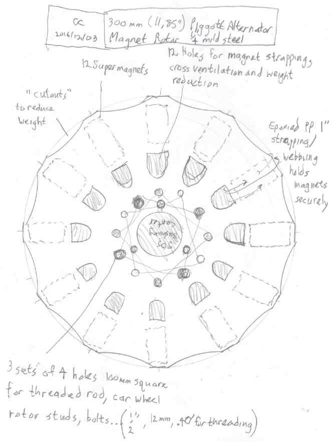 I
designed improved rotors for them, and took the drawings to Victoria
Waterjet to be cut out from 1/4" steel. (I didn't scan them first and
they still have them, but here's a quick drawing.)
I
designed improved rotors for them, and took the drawings to Victoria
Waterjet to be cut out from 1/4" steel. (I didn't scan them first and
they still have them, but here's a quick drawing.)
I think, if they can be made in varieties with from 1 to 3
or 4 stators in line on one shaft, they might just be the best and most
efficient answer for electrical generating projects for from under 1,
to between at least 4 and perhaps up to as much as 16, kilowatts.
The actual top ratings will be derived via temperature
measurements. Temperature rise at heavy loads will depend on the number
or stators and rotors, the electro-magnetic coupling at whatever RPM is
employed within an effective and safe range, making cast stators from
thermally conductive epoxy resin with various vent holes, and how
effectively the magnets acting as fan blades push cooling air through
the machine.
Since it was called a "refractory material", I left it
with Victoria Clay Arts pottery supply to try to come up with some
Boron Nitride powder, a compound added to epoxy (24 wt%) to make it
more thermally conductive. (They had never heard of it, so my hopes
aren't too high.) BN is composed of elements 5 and 7, one on each side
of element 6, carbon, and said to be able to form similar allotropes,
akin to "graphite", nano-thin "graphene" sheets, and nanotubes, and
"diamond". Unlike graphite, these are all electrical insulators, but
apparently (like graphite) quite thermally conductive. Electrical
conductors such as graphite powder might cause electromagnetic drag and
heat, even if they are good thermal conductors.
Meanwhile, I worked through in my head how I might make up
a mold for easily casting the stators. Plywood by itself doesn't appeal
to me (resin sticks to it) and all UHMW would be rather costly, but
UHMW center pieces with thin PE sheets lining a plywood top and bottom
might work well for a low cost.
Tesla Air Turbine
Tesla turbines have always seemed to hold a lot of
potential, with the actual inward spiraling flow path said to be up to
95% efficient. But they don't seem to have lived up to this potential
and have been used only occasionally. Major problems at the air entry
and exit points dramatically reduce the overall efficiency. But the air
intake always seems to be a thin slit. I think that's the main mistake.
I've come up with what I think is a solution for the air
intake, one especially suited to wind power. The air enters through a
"volute" spiral shape, a gradually narrowing "snail shell" path that
pushes more and more of it into the turbine disks around a considerable
portion of a single turn, with low constriction to the flow at any
point and overall. That's the other way around from how a centrifugal
pump - including a Tesla turbine pump - sends it out into a gradually
widening space. The small end of the windplant "horn" or OWC wave power
buoy top opening would fit to the volute end opening of the turbine,
the whole forming a smooth and gradually contracting airflow with
increasing air velocity into the turbine.
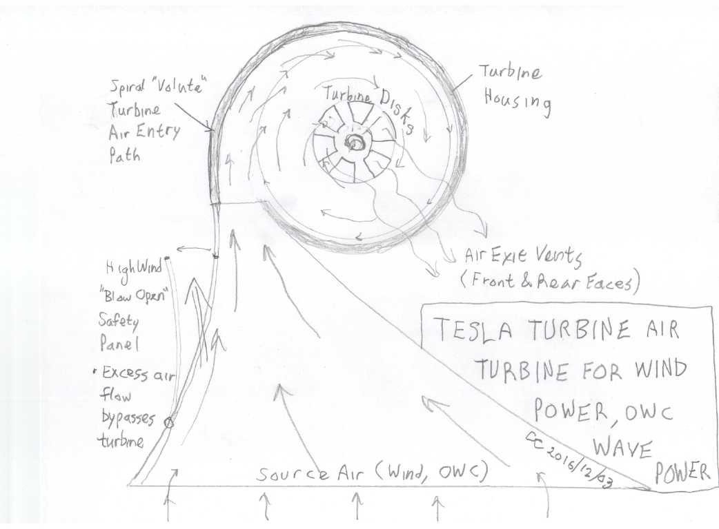 Tesla Turbine for wind power.
The air entry "horn" (drawn to fit on the paper) would be much bigger
to capture a lot of wind.
Potentially, the alternator could be in a fixed position and the
turbine unit, which must point into
the wind, could be mounted on the alternator shaft, or on a pulley
shaft connected thereto.
This gets around the problem of the wires twisting or needing a slip
ring.
A tail vane would be used to keep the unit pointing into the wind.
It will be interesting to see if the theoretical Betz
limit of 58% efficiency for a single stage windplant can be exceeded,
but of more interest (assuming any acceptable efficiency) is that the
spinning part is enclosed in a housing and noise should be minimal. The
chronic low frequency beat or propeller whir will be absent, and it
can't hit flying creatures.
I discovered that a 6" ABS plumbing pipe end cap, 3" wide,
potentially looks like a very good housing for the turbine. (But what
do I use for turbine disks?)
Underwater Turbine - "Spiral Staircase" Design
I could be wrong, but I didn't get the impression that
most of the units I saw were catching very much of the power from the
water flowing by. And most of them were simply flat paddles. I
considered a curved "(" blade as a potentially good shape for undershot
water wheel blades, acting as a wing or propeller as it entered and
exited the water. I thought it was a great idea, and probably it was,
because later I found others were already using it.
But the constantly changing angles as the wheel rotates
prevent employing a really efficient, optimal wing shape. A constant
angle of attack like a propeller facing the flow allows that.
Yet another choice might be a wheel with a "spiral"
(actually helix) design. Narrower blades, each extending only part way
across, are set at various different attack angles in the water and so
an even force is obtained with no especially strong or weak points, as
might be expected from a wheel with a small number of blades.
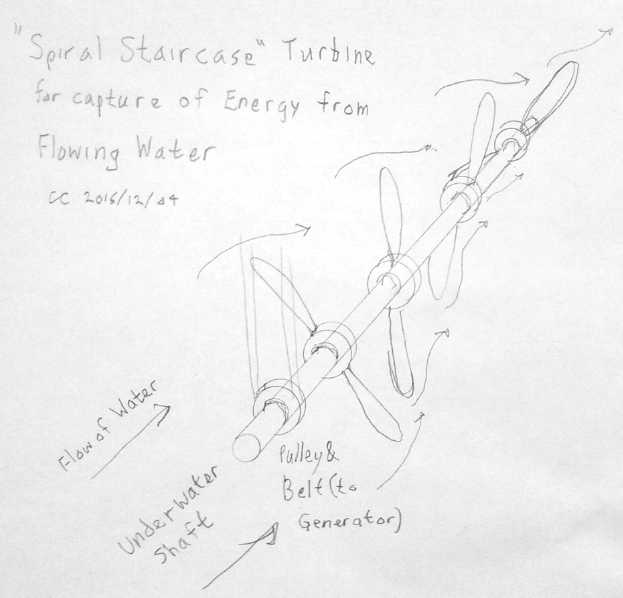 Then from
watching videos and other info I came up with a whole new idea for a
water flow turbine: a shaft with two-blade propellers facing into the
stream, with the propellers set at various rotation angles like a
"spiral [helical] staircase". Because each propeller (if doing work)
slows the flow, water from outside is drawn in behind each pair of
blades. Thus the series of propellers might catch the flow from a cross
sectional area much larger than the actual propeller diameter,
maximizing the energy capture. I think the optimum would be to have two
screws on one pontoon vessel, side by side and rotating opposite
directions. That would nearly double the energy and would probably be
more stable - with just one, there would be a sideways tipping force.
And the RPM would be much higher than a water wheel, so less (or even
no) gearing up to the generator would be needed.
Then from
watching videos and other info I came up with a whole new idea for a
water flow turbine: a shaft with two-blade propellers facing into the
stream, with the propellers set at various rotation angles like a
"spiral [helical] staircase". Because each propeller (if doing work)
slows the flow, water from outside is drawn in behind each pair of
blades. Thus the series of propellers might catch the flow from a cross
sectional area much larger than the actual propeller diameter,
maximizing the energy capture. I think the optimum would be to have two
screws on one pontoon vessel, side by side and rotating opposite
directions. That would nearly double the energy and would probably be
more stable - with just one, there would be a sideways tipping force.
And the RPM would be much higher than a water wheel, so less (or even
no) gearing up to the generator would be needed.
Of course the long shaft has to be below water, so the
next concern is how to get the rotary motion up out of the water for
the generator. Preferably without disturbing the flow very much. I'm
presently imagining a thin ring around one propeller, with gear teeth
along the back edge. But smaller pulleys and a belt might be as good or
better. A flat belt would present the least water friction.
To get a feel for how well the design should capture
energy, imagine how hard it would be to stop the shaft shown from
turning once it was going, in even a moderate flow of water.
Floats for Floating Hydro Units
Any water getting into an unattended floating unit is
going to eventually flood it. Since it's almost impossible to ensure
that no water will ever eventually leak in, automatic bilge pumps are
installed and maintained. Catamaran floating hydro units anchored in
flowing water would need two, and at least for smaller units it would
be nice to eliminate this complication. I think the way to do that is
to fill the entire interior with expanded foam so there is nowhere for
water to go inside.
A second consideration is that water levels change, and it
is undesirable that the mechanism turned by the water come into contact
with the bottom. The means I've thought of to prevent this is a pair of
"skis", one under each hull and extending down below the active
components. If the water becomes too shallow, the unit will simply rest
on its skis on the bottom. It may keep working or partly working until
still lower water levels are reached.
Along with this, is it undesirable that fish or debris
strike (or be struck by) the turning mechanism, both for the fish and
the mechanism. To prevent this I would put a stiff mesh, wrapped around
the "skis" and extending down from the hulls. The front would also be
mesh covered. The rear could be left open for any debris to escape.
Upon consideration of various possible ways of making such
floats, I decided that the easiest way to make a small 8 foot catamaran
unit would be to use expanded styrene insulating panels available at
building supply stores. These are commonly found as 2" x 2' x 8'
sheets. Each sheet would be split in half to 2" x 1' x 8', and four
such sheets would be glued together to expand the width to 8". The bows
and perhaps sterns would be shaped to minimize drag in the flowing
water. 3/4" plywood would be cut to line the top and (perhaps) the
bottom, 8" x 8' and matching the chosen bow shapes, and glued onto the
top and maybe the bottom of the floats. This provides solid mounting
surfaces for attachments. The entire glued-up hull would be wrapped in
polypropylene fabric (again... "landscaping fabric", stronger and
lighter than fiberglass and much nicer to work with!) and epoxied on as
a stiff skin.
Water (fresh) weighs about 62.3 pounds per cubic foot, so
16" x 1' x 8' of extruded foam, 10.67 cubic feet, will float up to 665
pounds. Of course one wants to stay way under that for stability.
Within reasonable limits, the design can be extended to hold more
weight and handle more energy: more pieces of foam for wider floats,
lengthening the floats with staggered joins in 8' foam sections, and so
on. Or the floats could be reduced to 6" wide and potentially be made
shorter for the smallest installations.
I think stainless steel tubing would be the choice for the
"skis". Each one would be a big "U" shape with a long flat bottom. The
ends would protrude through holes in the hulls fore and aft, and stick
up. Cross braces would extend between the floats at hull top level and
perhaps higher up to stabilize the assembly. There would be an enclosed
space(s) to keep the generator(s) and electronic components (diodes
& ??) dry.
Sprint - Next Fixed Ratio Chain Drive Test
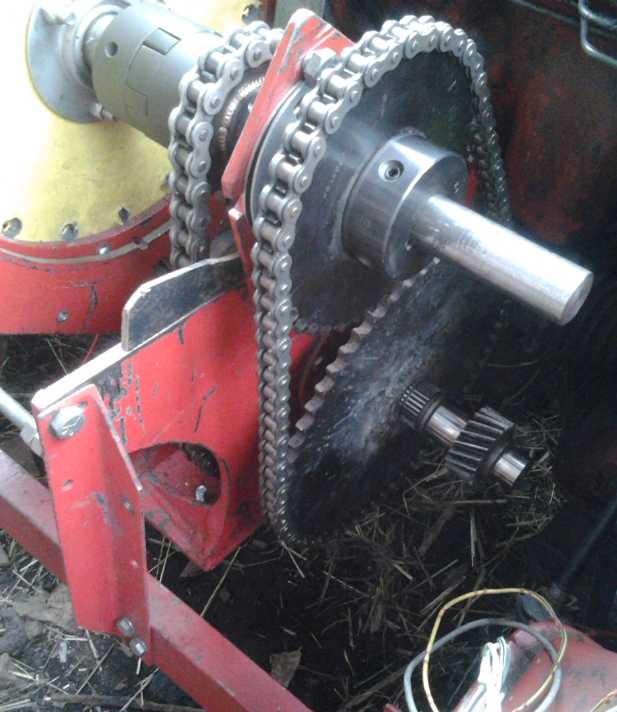 In mid month I
did manage to do a bit of work on the Sprint car. I had the thought
that if I used larger chain sprockets, the forces on the chain would be
smaller and hopefully it would have less tendency to jam. So I unwelded
the 36 tooth sprocket from the odd size differential shaft hub and put
on a 60 tooth one, the largest I happened to have. Then the 36 tooth
one seemed just about right to use for the motor shaft side, so I
welded it onto a 1" I.D. hub. The two proved to be exactly the largest
two sprockets that would fit without bumping into each other. (Whew!)
This pair might result in a final differential reduction ratio of
around 12 to 1 between motor and car wheel.
In mid month I
did manage to do a bit of work on the Sprint car. I had the thought
that if I used larger chain sprockets, the forces on the chain would be
smaller and hopefully it would have less tendency to jam. So I unwelded
the 36 tooth sprocket from the odd size differential shaft hub and put
on a 60 tooth one, the largest I happened to have. Then the 36 tooth
one seemed just about right to use for the motor shaft side, so I
welded it onto a 1" I.D. hub. The two proved to be exactly the largest
two sprockets that would fit without bumping into each other. (Whew!)
This pair might result in a final differential reduction ratio of
around 12 to 1 between motor and car wheel.
Weather, and other tasks, then prevented going any
further. And I still haven't tried to repair the Kelly motor controller
needed to run the motor.
The chain still seemed to jam. On December 4th I made some
adjustments resulting in absurdly loose chains, but it was better.
Chain sprocket alignment seems to be quite critical. Sufficient
precision will be hard to achieve on the Sprint. Knowing that 10-speed
bicycle chains are misaligned in normal operation, I wouldn't have
guessed that would be the case without seeing it.
End of the Old e-Motorcycle Story
As I have just used the old 60 tooth chain sprocket in the
Sprint car experiments, perhaps this is a time to complete an old story
mostly from TE News issues perhaps around 1/2 the number of this one. I
bought the sprocket back then and used it in an experiment with the
heavy old motorcycle to get more reduction from the 12(?) tooth
sprocket on the motor to the back wheel than with the 48 (or was it
54?) tooth sprocket. I was frustrated because the sprockets available
locally only went up to 60 teeth - and it never occurred to me there
might be larger ones available to order. I'd have gone much higher if I
had found a larger sprocket. Naturally it was only a little bigger
reduction than the 54 tooth one and it still wasn't enough.
I had always intended to get back to the motorcycle
sometime, and sometime later I saw an electric motorcycle with a huge
sprocket on the back wheel with somewhere around 100 teeth, and heard
about "Rebel Gears", who make them. And recently someone told me he had
once made his own chain sprockets. That idea had certainly never
occurred to me either.
But a few months ago someone making his own bikes saw the
bike and asked to buy it for certain parts he wanted, especially the
front forks and suspension. As I might never get back to the project
and had started thinking of moving, I sold it to him cheap, to get rid
of one large and heavy piece of clutter that was a low priority project
I might never get back to.
If I had obtained a huge sprocket, it would have given a
better reduction ratio and the beast could unquestionably have been
made rideable, as it was already on the verge. I'm not sure the top
speed would have been very high. (Again the reason for a variable
transmission - also for making the motors able to run at higher RPM.s!)
Electric Suzuki Swift
The Swift EV has run so well I almost forgot to mention
it. I've been using it for most of my driving. It has the range to take
me anywhere within the greater Victoria area and home again. Owing to
weather and lack of time I have yet to return the batteries and install
my own.
In Passing
(Miscellaneous topics, editorial comments & opinionated rants)
"Voter" 'Date a Politician' App
Hunter Scarborough, interviewed on Kitco News on November
7th just before the US elections, wrote a computer app called "Voter",
a "voter dating app" which matches up issues the user sees as important
with what candidates have done in the past that's relevant and what
they have said they will do. This will make a good start at helping
people find out which candidate is really most in line with the user's
own ideas of what ought to be done. It could go a long way toward
uncovering the hypocritical practices of a number of recent (if not
earlier) candidates, who say one thing and do another, and eliminate
them from future consideration for public office.
He started writing it in September 2015 out of frustration
with trying to find out where candidates actually stood on various
issues. He was asked what he saw ahead, now that the national election
would be over in a day? He replied that he was quite excited about it,
that there were important civic elections coming next year, including
in New York city, where the public would have even less chance to find
out the positions and previous actions of the candidates. Even the
alternative media probably won't have much coverage of local affairs.
I see it as a step towards my idea of
www.CampaynCentral.com (See http://HandsOnDemocracy.org).
Perhaps
it
is even an alternative to it. It addresses the concerns of
that piece of the puzzle of our political problems. I see some
weaknesses to the design, but I am thrilled to see that some other
peoples' thoughts are running in such directions! May it be the start
of a wave!
The Power of Groups With Intentions
Each year the world's top bankers meet in Basil,
Switzerland. And the Bilderberger group of the richest and most
powerful meet in various places. They have specific intentions
- to figure out how better to control the world's economy, expand their
business empires, eliminate outside competition and extract more wealth
from the public. And these plans are probably formulated and explored
in one on one discussions and planned out by very small groups. Few if
any would be subjected to votes by the whole assembly.
Many have a negative reaction to these organizations,
because it is realized that they are very influential and that they are
there to put their own narrow interests ahead of the public interest.
Negative emotions can achieve little. Despising these people and groups
or protesting against them accomplishes little except perhaps to bring
awareness of their existence to public attention. Without plans and
designs of our own, we all just drift with the flow created by those
who take council together, co-ordinate, and put energy and time into
their plans. And so we become the unwitting victims of their plans,
executed through their corporate empires. (Computer tracing of the
tangled web of corporate share ownerships has disclosed that most
corporations eventually trace back to considerably less than 100
individuals controlling 80 or 90% of the world's economy.)
Positive action can move mountains. However unworthy their
motivations, the groups that meet together are making positive
decisions for the future. By contrast, those we elect to represent us
have today mostly arrived at the point of having no intentions
except to govern day to day and earn a salary. They too drift in the
path of least resistance and are subject to the wills of those with
developed agendas.
We elect legislatures of hundreds of people, thinking that
among all those, there are bound to be a few "movers and shakers" who
will make things better. But how does one person with an idea make
headway in such a mob, especially when many of them are beholden to
influences from those with definite and corrupt intentions? Does the
number make them far more effective at formulating and passing
legislation, or do they all just stumble and mill about, and rubber
stamp whatever is pressed upon them from outside sources? Might a
legislature of seven or ten of a nation's best and brightest,
discussing a subject together, have sufficient diversity of opinion and
sufficient resources at their disposal to make decisions just as well
as hundreds of "yes men"? And would those decisions not be better ones
if these small groups held the core values as guides in all decisions?
And if citizens with good ideas were able to communicate those ideas to
them to be considered during the decision making process? And if the
constitution itself provided for change and growth instead of
exhaulting a specific way of doing things that might have been
appropriate when it was written, but which causes trouble as society
changes and grows?
Why do we as citizens not consider coming together for
more noble reasons - to create positive change, to consider means for
evolving our systems of democracy and economic governance to be more
effective in the future and for the good of all? We too can develop
plans and agendas. It is said that the power of a group, if all are
pulling together at the same time with common intentions, is not an
arithmetic sum but more equal to the square of the numbers involved -
provided of course that they aren't just getting in each other's way.
Ten men can't sheer a sheep ten times faster than one because there
isn't room for them all around the sheep... can a multitude of
legislators make better decisions than a few?
Probably any small group of individuals, if they are able
to come together and form valuable, cohesive designs for positive
change, and then to broadcast these to the public, will find that they
will be as influential as the bankers or the Bilderbergers, even if
they cannot give such immediate effect to their plans. But in fact,
provided their designs are pressed forward and not ignored or
forgotten, delays between working out plans from intentions and their
implementation can help the process to flow smoothly, gradually and
peacefully, without jarring the stability of society. And there is more
time to consider whether doing what is proposed is actually desirable.
After all, most people are good hearted and most of society works quite
well.
But such "Social Sustainability Design Teams", meeting
with the intention to forward the core values of Quality of
Life, Growth, and Equality, with Empathy, Compassion and Love, can
doubtless change and reverse the direction of "social drift" of the
political and economic flows as effectively as the business oriented
groups or more so, to move political systems and society - including
the ways businesses will be run - in positive directions. And local
group meetings, or communications by e-mail may perhaps be as effective
as large but infrequent group gatherings or even more so. A number of
such groups attacking various social problems can supplement and
perhaps supplant global meetings as "leavening" groups for societal
changes.
At http://www.HandsOnDemocracy.org
are a new idea or two by me, and a link (in footnote in #9) to a new
procedure by Daniel Raphael PhD for Social Sustainability Design Teams
to address whatever social, economic or political problem they have
decided to tackle. (The link direct: http://www.saers.com/recorder/craig/democracy/DesignTeamProcedure.pdf
)
USA "Electoral College" System needs to be Dropped
Back when the US constitution was designed, it was
discerned that much of the population was what today might politely be
called "rabble". It was uneducated, illiterate and suspicious of
government in any form. But the colonies couldn't run without
government. It was decided that everyone could elect a wise local
person, someone they knew and trusted, and that that person would then
join a group, the "Electoral College", that would meet to select the
next president. This group was to study the candidates and then decide.
This is an example of how times and conditions have
entirely changed. As the public became more aware of and interested in
who was running for president, the candidates for the electoral college
soon had to start saying who they were going to vote for in advance,
which negated the whole purpose of the college. And as the population
grew, the public, instead of not knowing the candidates for president,
no longer knew nor cared who the candidates for the the electoral
college were.
One elector, elected on the basis he would choose a
specific candidate (sometime around 1970) then changed his mind and
voted otherwise. This caused quite a stir, and a law was passed that
prevented them from doing so in the future. (...If I recall correctly.
At least, passing such a law was certainly discussed.) The electoral
college system thus became completely superfluous.
Those who compose the electoral college today are hardly
known. But in the last highly polarized election, some of those whose
candidate lost think they see a new way to "game the [obsolete]
system", to change the outcome of the defeat at all costs: they have
threatened the electors who were elected to vote for the winning
candidate with death or bodily harm, or harm to their families, unless
they change their minds and vote for the loser. Should this tactic
succeed, it would be the end of peaceful democracy in the USA. I
personally don't think it will. But people may (or may not) be
needlessly hurt and killed. They have certainly been threatened. And
good people will not be very enthusiastic about putting their name
forward for the next electoral college, especially if there actually is
violence.
All this shows us how systems need to be able to adapt and
grow as society changes and its needs change. The once good idea of the
electoral college has now become not only useless but a threat to
democracy itself. Likewise, the houses of Congress and the Senate have
become leverage points for corrupt, profiteering economic interests to
gain control over the government by virtually buying the members. It
has been said that hardly a decision in decades has been made to
benefit the American people, but rather each one has had a corrupt
'oligarchy', 'shadow government', 'deep state', or 'corporatocracy'
entity as its beneficiary.
Today the system is so broken there is no system.
Different parts of the US government are at odds even with each other.
Thus we have had such anomalies as Pentagon backed Syrian rebels
fighting CIA backed Syrian rebels. The new president will find there
are problems which he has no solution for or no power to affect, so the
answer will be 'more of the same' as enacted from somewhere in the
depths of the machine, with corporate interests missing no opportunity
to increase their control over the legislative processes.
"Draining the swamp" is of little use when a muddy stream
is continuously filling it up again. In this case careful plans need to
be formulated to have the swamp bulldozed over and filled in, to
eliminate the low spots, the power vacuums that simply fill up with
more muddy water.
The power, the various powers being exercised, needs to be
brought under the effective control of the public, who are the ultimate
source of power in a democracy when they choose to organize and
exercise it. If the whole swamp was filled in suddenly it would be a
huge shock. Done gradually, yet still pressing ahead peacefully with
the evolution of the systems, it can be done with little social
complaint and upheaval.
The USA is always a good example of what's right and
what's wrong on the planet, and so influential that its gyrations are
international news, but there are few if any lands that could be said
to be much better - or which would be better if they had similar power
at their disposal.
More Precious Metals Price Manipulation
We entered this year with the lowest prices for precious
metals in a decade, in spite of general inflation raising virtually all
other prices. Now, silver mines that were planning in January to shut
down this year, have continued operation because of rising prices. Now
that the threat of mine closures is gone, precious metal prices have
once more taken some heavy hits in the last month. All of them - gold
silver and platinum - rise and fall pretty much in the same hour and
the graphs are often virtually interchangeable.
In two days after the US election, gold contracts said to
amount to 8000 tons of gold were dumped on the market to cause the
price to drop. I must remark that that is virtually the entire amount
of gold reputedly held by the US government in Fort Knox,
accumulated over decades (it's probably all gone)... the whole works
was "panic sold" in two days in such a manner as to fetch the lowest
possible price. Of course, it was doubtless all sold, and snapped up,
by tipped-off and colluding banks and federal government agencies, to
be "panic sold" back to each other later to reduce the price even
further, and no one will ever ask for physical delivery of actual gold.
Some people call this price manipulation fraud. If more than a fraction
of a percent of people started buying the actual metals, the price
rises would leave people breathless.
It was also announced by the US Mint that no more 2016
Silver Eagle coins would be sold this year, after a sudden surge in
sales in October depleted supplies. No need to raise the price on
something that just isn't available! Of course the prices are still up
from a year ago, and some time the manipulations will get so out of
hand that everyone will start seeing through them. Precious metals are
real property that will, perhaps in fits and starts, keep up with
inflation, and they hold their value when hyperinflation destroys the
perceived value of fiat currency.
Newsletters Index/Highlights: http://www.TurquoiseEnergy.com/news/index.html
Construction Manuals and information:
- Electric Hubcap Family Motors - Turquoise Motor Controllers
- Preliminary Ni-Mn, Ni-Ni Battery Making book
Products Catalog
(Will accept BITCOIN digital currency)
...all at: http://www.TurquoiseEnergy.com/
(orders: e-mail craig@saers.com)
Electric Hubcap Motor Systems - Electric Transport
Electric
Hubcap motor, Chevy Sprint & Infinitely Variable Transmission
Differential Torque Converter in the Sprint? - Another fixed ratio
test
I decided to continue experimenting with the car even as I
worked on what I hope will be the start of a "production model"
variable transmission. I still hadn't had a really successful fixed
ratio differential drive test. I can hardly help but gain experience
and knowledge, which is likely to improve the final product as well as
to hopefully get the Sprint moving. On the 'production model' idea I'm
presently still doing the "differential gear" unit, which is a rather
different part of the work. The experiments on the car are the
components that will come later on in the 'production' transmission.
I decided to forget the big V-belt pulley, and instead put
a bigger chain sprocket on the differential so that the force required
on the chain is less. That would make it last longer in use, and also
(I presume) reduce the strong tendency of the last two to jam up under
load. The hub with the 36 tooth sprocket had been specially bored out
to the size for the differential shaft, and now there seemed to be no
chance I'd use it there, so on the 19th I ground off the welds to
liberate the hub (ouch, it took an hour), and welded on a 60 tooth one,
which would require only 60% as much torque to turn. I'd have gone even
bigger if I'd had a bigger sprocket. Since the "idle point" is 1.5 to 1
reduction, a 40 tooth sprocket on the drive shaft would have been
"idle". So I needed one near that size to get a high final reduction
ratio with the torque to get the car rolling. Of course I had the 36...
and nothing else close. That, 36 teeth to 60, would make a somewhat
higher differential reduction than the 9 to 1 with the 20 and 36 tooth
sprockets. Perhaps between about 12 and 14 to 1. If the chains don't
jam, that should at least move the car handily up and down hills on the
lawn, even if top speed would be under 20 Km/H.
And I had the welder set up, so it was the time to do it.
I welded the 36 tooth sprocket to a 1" center hub for the motor shaft.
The sprockets I had, and thus used, were fortuitous. They nearly
touched each other when mounted on their shafts. Any bigger on either
end and they wouldn't have fit. I had given this no thought.
While I was at it I reassembled the motor, which had been
sitting on the bench for a month now. My quick "one hour" job of doing
the 60 tooth sprocket turned into 3-1/2 hours. But I got more done.
On the 20th I did a few small things and made up the
chain. I put it in and tried turning the motor by hand. It looked like
the car might move, then it stopped and did nothing. At first I
couldn't figure out what was slipping. Finally I noticed that the 8 or
so tack welds on the 60 tooth sprocket had broken, so the sprocket was
turning freely around its own hub. I had turned the wire feed welder
down low and marveled that it still made an arc in about the same place
and still put out weld. But evidently it wasn't melting and bonding to
the rotor metal, just sitting on top of it.
It wasn't until the 23rd that I was able to weld. It
rained a lot and I weld outside, and I had other matters to attend to.
I got it installed except for the outer spacer bracket to keep the
shafts in line. I turned the motor, and while there was no visible
shaft twist of note, it still seemed to jam up at a certain tension
level. But I didn't have a pulley on the motor shaft and was turning it
from small protrusions. Then it started to rain again.
On December 4th it was nice out and I thought I'd give it
another try before finishing up this newsletter. I put the pulley on to
get more turning leverage. It still jammed. The slack part of the chain
seemed to be pushed over sideways between shafts, and looking closely I
could see that the chain sprockets were slightly angled to each other -
aha! I adjusted the motor shaft, looser to be more closely parallel to
the other shaft. The chains were then quite loose, but the alignment
was better, and it seemed to move considerably more smoothly and go up
some rises without jamming. Yes, chain alignment is definitely very
critical. I still hadn't expected that from chains, when a 10-speed
bike shifts them considerably back and forth. Perhaps bicycle chains
are specially made?
After all that, there is still that niggly detail of the
broken motor controller. I thought I'd get away from broken motor
controllers by buying one. Sigh!
Asymmetric Epicyclic gear with Spur Gears: Gears & Gear Cutting
I had found various changes necessary from my
original vision of the asymmetric differential gear assembly. The
diameter and width both had to be reduced, and it appeared only 4 pairs
of spur gears could be fitted in instead of 6 or 8. Every change made
for more pressure on each gear tooth to the point where I was losing
lose confidence in using plastic gears.
I started thinking of the other design, the "double sun
planetary gear" or perhaps we might just call it more generically an
"asymmetric epicyclic spur gear assembly". Hmm... that's even longer!
Some gears would have to change, but with both pinions/planetaries on
one axle instead of beside each other, 6 or 8 could be fitted. That was
at least some improvement.
On the 16th I drew up a cover plate to be waterjet cut
with the all the holes for all the potential axles for either type of
gear exactly positioned. In doing that, I discovered that it wouldn't
even fit 4 pairs of planets for the differential type - the teeth of
adjacent pairs slightly overlapped. So It only has holes for 3 pairs,
not even 4. A couple of days later I remembered that the linking gear
could have any reasonable number of teeth and it would still work
exactly the same. If I shrank them from 16 teeth to 14, there would be
room for 4 pairs. The positions would change a bit and they would fit.
But I started getting more interested in the other type.
With the additional size constraints even the 30 tooth gear would no
longer fit. I designed it for center gears of 22 and 26 teeth, and the
double planets on one shaft, of 12 and 16 teeth. Once again it looked
like 8 wouldn't fit. I put in axle holes for 6 of them. The operation
gets interesting.
If one turns the output end (26 teeth) around once with
the hub stationary, the planets (12 teeth) will turn around 2-2/12 or
2.1667 times. The larger 16 tooth planets on the same shaft will also
turn 2.1667 times, which means turning through 34.6667 teeth. Since the
control end has 22 teeth, it rotates 1.576 times, for one rotation of
the output side. (And in the same direction.) That would seem to make
it a small reduction of 1.6 to 1 - but only if the drum is stationary.
If instead the output is held stationary and the drum is
rotated one turn, again the 12 tooth gears rotate 2.1667 times against
the inner gear, but this time the drum holding the 12 tooth gears has
also rotated once, making it 3.1667 times. The 16 tooth gears thus move
by 50.6667 teeth, and so the 22 tooth gear has turned 2.30 times. For
one rotation of the drum.
This then is the "idle point" ratio. If the drive to the
control end is 2.3 times faster than the drive to the drum, the output
shaft and hence the vehicle won't move. A higher ratio will move it
forward (same direction as drum and control shaft), and a lower one
will move it backward. Assuming the gears can take the forces without
breaking or deforming.
Electricity
Generation
Improved
High-Powered Hugh Piggott Frictionless Axial Flux Alternators
Continuing this theme from last month, it seemed to me it
should be practical to make highly efficient, frictionless Piggott
generators for various power levels up as high as 6KW and perhaps well
beyond that. The basic 500 watt model (among others) has in fact been
being made at home, in workshops and by small scale manufacture for
home windplants for a couple of decades now. I want to improve on the
basic design with blown air cooling to raise its available power, and
to put multiple alternator segments onto one shaft to multiply the
power by the number of segments. This will be more compact and lighter
than duplicating the cases and all parts for each unit of energy to be
converted to electricity.
Out of sequence here, on the 20th I dug out my How To
Build a Wind Turbine Book (Hugh Piggott 2005 edition) and looked up
the specs for the alternator in question. The intended rotor diameter
is 10 feet with three 5 foot blades. The cut-in windspeed is 7 MPH
giving 140 RPM, and the rated windspeed is 17 MPH, giving 280 RPM and
500 watts. The 9 coils use 7 pounds of copper. I was surprised the
RPM.s for that power were so low, and I had to revise some figures
below. In fact, it seemed to me that they would handle substantially
more power and at lower speeds than I was expecting.
The original windplants are loosely rated for 500 watts or
more but in a stronger wind they can overheat making 1KW. Much of the
heating problem must surely be attributed to the fact that they have
dead air space around the stator and its wiring instead of cooling fans
and blowing air. Plus, the stators are cast in polyester resin, which
doesn't conduct heat well. On the other hand, with no iron in the
stator, the iron losses are zero, generating no heat.
Notwithstanding the air core coils, evidently the magnet
rotors are usually even backed off to have a somewhat larger flux gap,
because a full battery charging load tends to stall the propellers. So
evidently more than sufficient electromagnetic coupling is available to
get such ratings as 1KW even at very low RPM. I was really at first
hoping, with well ventilated parts, to get a kilowatt out of each
stator, which I conservatively derated to 750 watts. But looking
further, the windplant speed for 1 KW would be under about 600 RPM.
(Wow!) At higher RPM, one should get more output per the square of the
speed - and within limits, more cooling air flow to match it. It would
be 2KW at 850 RPM and 4KW at 1200. I consider that 2000 RPM should
probably be the maximum allowed speed, which would be 11000 watts. That
would surely overheat. But the equipment could be programmed or
configured to draw lower power even at higher RPM, allowing more
airflow and cooling per output watt. I'm tempted to think each segment
could handle at least 2 kilowatts continuous, and maybe even 3 or 4.
So I drew up a 300mm (11.85") steel rotor plan to take out
to Victoria Waterjet. I'm having 4 of them made. With molds and jigs
for making the stators, I can make 2 generators.
Starting with a 2 segment generator, 4 (hopefully) to 8
(wishfully) KW potential rating, how big would it be? Each segment
requires a rotor plus a stator, and one more rotor on the far end. The
outer steel rotors are 7/8" thick and each inner rotor and each stator
is about 5/8", counting air gaps between components. For a two segment
machine, 29/8 or 3.6". Add about 3.4" for the ends makes it 7" long. If
I make it 8" it'll be more sure to hold everything - better extra room
than not enough. The outer diameter will be about 15". At first I hoped
to find short pieces of PVC culvert pipe of that dimension rather than
making cylinders for cases, but I didn't find any the right size. The
end pieces could be PP-epoxy... or even plywood for prototypes. Or
aluminum plate.
How heavy would it be? My sample 12" x 1/4" steel rotor is
3.3Kg. Each magnet is
118g. Each SDS bushing is 628g. That's about 5350g per steel rotor:
10700g for the two end rotors.
A one foot piece of 1" steel shaft measured 1117g. A
couple of disks of plastic that might stand in for an interior rotor
were 1230g, to which another 12 magnets must be added, making 1416g,
total 2646g per interior rotor. Add some threaded rods and nuts and
we're up to 15Kg (ouch!) for the rotating parts for a 2 segment machine
- hopefully at least 3KW (4HP) continuous without overheating and maybe
4KW (over 5 HP).
Stators... A coil that looks about right (well, probably
too small) weighs 150g. There are 9 coils per stator. The plastic might
be another 650g for a total of 2Kg per stator: 4Kg. Then there's the
plastic outer casing... add 2Kg?
We've hit about 21Kg or more, 45 pounds, and rather evenly
distributed through the machine. Except maybe for making extra holes in
the steel rotors I don't see how that's to be cut down much with this
design. (I made them a bit "petal" shaped with some small 'voids'(?)
between magnets around the rim.) I like lightweight, especially if it's
going onto a floating unit or up a pole where the wind is, but I
suppose this sort of weight is really pretty typical for electrical
machines with those sorts of power ratings... or maybe even on the
light side, depending what the power rating actually turns out to be.
If we doubled it to 4 segments (8 to 16 KW) the two
additional segments only add 2Kg (stator) + 2646g (interior rotor),
times 2 of each, 9292g, and add a bit of case length etc takes us up to
perhaps 32Kg (70 pounds) instead of 42Kg, the weight for two separate
2-segment generators. 4 segments, the case being maybe 10" long, is
probably about the maximum limit to keep the threaded rods holding the
inner rotors, now 3, stiff. It's also a lot of weight to pack around.
(3 segment units would be about 26Kg/57# and 9" long.)
He remarked that I really needed to learn how to use CAD
software. In principle I agree. I certainly would like to. But I
remember last time, with the reluctance motor design... their machine
didn't like the OpenSCAD exported output, and when I redid it in
LibreCAD, he still had to virtually redo it anyway. And since that was
the only time I had used that non-intuitive program, I don't remember
how to work it and would be starting over again. I bought a 'new' more
'modern' computer, and I tried to get Rhino 3D (which is what they use)
a couple of months ago, but not only is it costly, there's no Linux
version nor one that would work on my older Macintosh. Hence this time
I made and brought the paper drawings. These aren't something I do very
often. I don't suppose I'll get the finished rotors before Christmas.
I mentioned this to a friend, and was given a copy of an
older CAD program that would run on one of my older computers, with a
printed manual. I'll try this out when I have a chance and see how it
goes.
In the meantime I gave some thought to cases. The outer
rim should be quite thick so that even if magnets do break loose or if
there's other debris somehow sent flying by the spinning rotors, it
doesn't break through the rim, fly out and damage anything or injure
anyone. (...or lose a magnet(s) or other repairable parts) There seemed
to be no scraps of 14" culvert pipe to be had. I would have had to
order a full length piece, and it would be a special order. Then I
started to think of how one can bend plastic with heat. An 8 foot piece
of 1/8" lexan/polycarbonate, or PVC sheet, could be rolled up and glued
to itself. The lexan could be interesting, to make a transparent bodied
generator. But whatever it is would have drilled vent holes, small
holes around the rim, to expel heated air.
The end caps could, for example, be a 14" diameter
piece and a 15" piece of plastic or aluminum... or even plywood?...
glued or bolted together. With vent holes near the bearings in the
middle.
In case more mechanical turning power is available than
the generator can handle, it's not hard to increase the number of
rotors and stators. The same ones would be reused, adding however many
more are needed, with the same case, end caps and bearings. Then it is
only necessary to mount them on a longer shaft and make a new, longer
outer rim case. After the initial length needed to fit the bearings and
shaft fittings, each new segment, a stator plus a middle rotor, only
adds 1.25" to the length. So a 4 segment unit, good to somewhere from
8(?) to 16(?) KW, is only 3.75" longer than the basic single segment
one.
Or perhaps they should all (unless space is at a premium)
be made long enough to accommodate 4 segments - still only 10" of so -
and populated with just the number expected to be needed. Then if more
oompf is required, just add the extra internal components, and only the
weight changes. Having the case with its mountings and connections stay
the same should be quite valuable, not in theory, but in practice
definitely.
Late on the 19th I thought to check on youtube.... sure
enough, there were videos about Piggott alternators and windplants,
including videos by Hugh Piggott himself that had lots of design
philosophy and tips.
It seems he's leaning back to ferrite magnets instead of
supermagnets for windplants mainly because of the corrosion problems of
the Neodymium ones. Even beyond the reactive neodymium, they are after
all mostly iron, and corrode as such. If they rust they expand and
start rubbing on the stator. "You can't corrode the ferrite magnets any
more than you can a teacup, because they're ceramic." His observations
are based on long experience, since he's been doing small wind power
plants for over 20 years with both types, and gets to see what happens
to the old ones, why they finally die or need repair.
Using weaker ferrite magnets does however mean (he says)
going up a rotor size and using more copper wire to get the same power
ratings. That's more bulk, more weight, and copper wire is costly. In
addition to making them safe at much higher RPM.s, I think the new way
I securely mount the supermagnets by wrapping them to the rotor with
epoxied polypropylene strapping/webbing, through a slot, should protect
them significantly better than most other techniques and pretty much
solve the problem. It would take more than a little rubbing on the
stator or a stray shard of crap to get through the thick epoxied
strapping and penetrate the magnet's protective coating. Sometimes
little details can make practical what might otherwise be abandoned in
favor of a different setup.
But I wonder, if I make multi-stator units with center
rotors, if ferrite magnets might not pass the strong magnet fields of
the outer supermagnet rotors along from rotor to rotor and be almost as
effective as they are, simply by reinforcing their fields? In fact,
even just iron or steel blocks in place of magnets in inner rotors
might have that effect, to a lesser extent. That would cut costs if it
works well since ferrite magnets are cheap. Hmm!
I turn now to the resin-cast stators and getting the heat
out of them. One aspect is to make as many ventilation holes in the
castings as is consistent with strength, and to that end to use epoxy
resin rather than polyester. And perhaps some convolutions in the
surface. The other point is to use more heat conductive resin. More
on-line research on December 1st found that regular epoxy is about .35
whatever those heat conductivity units were. Adding 24 wt% boron
nitride makes it about 3 times better - .9 to 1.4. That or aluminum
powder seems to be what "heat conductive epoxies" use, but the aluminum
isn't quite as good, and there might be magnetically induced electrical
conduction losses, which would make heat.
Tesla Turbine
Windplant?
In essence, the Tesla turbine can be a "bladeless"
replacement for a VAWT
unit. Since it relies on skin effect for the moving air to
push it around, it needs its flat disks close together, so a large - or
at least wide - one will require many disks.
When the tiny Tesla turbine and Tesla one-way air valve
with no moving parts arrived from EpicPhysics.com, I was rather
disappointed. I didn't see much difference in resistance blowing into
the tiny one-way valve from either end. Then, the air inlets on the
turbine
were so small I could hardly blow into it, and it didn't turn from
blowing, or even stay turning if I spun it while blowing. Only an air
compressor would turn it, with something like 30-40 PSI. It then
started turning at great speed. And that was freespinning, with the
little generator disconnected. I have little doubt that the turbine is
in principle a fine idea, but to have one that would operate at the
low air pressures provided by wind power - which are also said to run a
Tesla turbine most efficiently - it certainly needed to have larger
ducts for the air to enter through.
Of course, I would build a
substantially larger turbine unit for any real power project. Let's
see... 6" diameter wheels inside might be a good size with the high
RPM.s
normally attained by these turbines, but considering the lower
pressures would make for lower speeds. If the wind was 20 Km/Hr that's
20/3.6=5.6 m/sec. If one took 3/4" inside the outer rim of 6" as an air
pressure point, that would be a radius of about:
2.25" or 2.25" * .0254 m/" = .057 m radius
2 * π * .057 m =
.36 m circumference
5.6 m/sec / .36 m/revolution = 15.6 RPSec
15.6 RPS * 60 sec/min = 938 RPM.
Call it 1000 RPM. Wow, that's surprisingly low. But higher
windspeeds are going to increase that. Also, as the wind is
concentrated, should
there not be some sort of venturi effect speeding it up? A 4x speedup
would put the RPM around 4000, and faster in stronger winds. In any
event, one has to direct all that wind pressure into the turbine, and
the smaller the opening below a certain range, the more resistance and
the less flow there can be. Perhaps an even larger diameter
should be used? Or perhaps the turbine should be very wide,
with a large number of vanes across, to catch a wider swath of wind?
On the 28th I watched a video of someone making a "micro
tesla turbine" out of carefully machined brass and other metals. It was
beautiful, meticulous work. It turned at over 100,000 RPM with 30 PSI
air pressure going in. I didn't want to put that kind of time into it,
and was thinking things like "He could have used brass pipe instead of
carving out a solid brass cylinder." An absolutely perfectly round,
lathe bored, polished smooth inner rim was nice, but for low air
pressure in a large size, probably much less vital.
In another video a larger unit (10" diameter?) powered by
steam ran nicely until it hit maybe 9000 RPM. Then a ball bearing
failed and smoke came out. It finally ground to a stop making noises.
It would seem it would take quite a wind to get a 6" wind power unit up
to that speed, and it should tolerate higher speed than 10". But I
should probably check into small bearings made for those sort of high
RPM.s. From dremmel tools and routers? Then again, those tools don't
run continuously like a windplant can, so still better bearings might
be desirable.
While I'm on the subject, there was also more info on
Wikipedia.org and several Tesla turbine designs at instructables.com .
It suddenly occurred to me that I had some ABS plumbing
pipe end caps. The one for 6" pipe looked perfect for a large, sturdy
Tesla turbine housing. It was about 6.6" inside diameter (over 168 mm
at the open end). It was round to within the limits of measureability
with a ruler, surely under 1/2 a millimeter, and the surface was
smooth. A thick, flat piece of plastic could be turned on the lathe and
fitted as a cover for the open end. Pieces of plastic could be glued
securely to the outsides for screws and mounting flanges. (Being ABS,
it would have to be painted or kept out of the sun. UV rays deteriorate
ABS rather quickly.) Suddenly it seemed the project was notably farther
along than before the video, and without any building on my part.
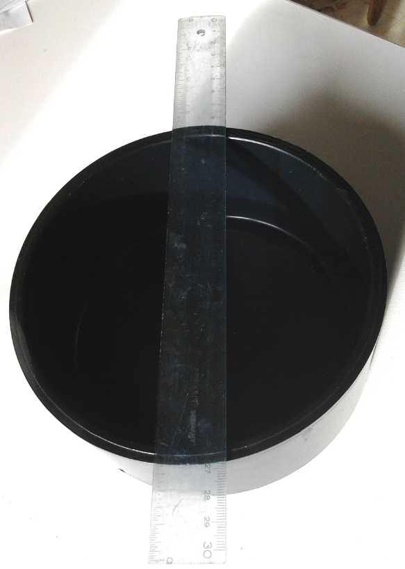 6" ABS Plumbing Pipe End Cap (6.6" x 3.1"
I.D.): A Good Housing for the Tesla Turbine?
6" ABS Plumbing Pipe End Cap (6.6" x 3.1"
I.D.): A Good Housing for the Tesla Turbine?
The next tricky part will be making or finding thin rotor
disks and even thinner spacer disks between them. In the video coffee
can lids(?) were cut into tiny rotor disks (carefully drilled and then
turned to perfection on a lathe). This one would take whole coffee can
lids! In fact they weren't quite big enough. Anyway I think disks with
a rough surface should be better than smooth disks. (Besides, I buy raw
coffee beans at GreenBeanery.ca and roast them myself in a 'Toastess'
hot air popcorn popper, so I never buy coffee cans.)
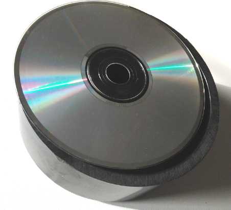
In a couple of videos people had used CD.s for disks. This
was clever, but rather small. Also I was afraid they might break at
high RPM. However I wondered idly if they would fit a 4" ABS pipe end
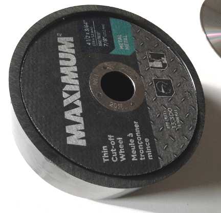
for a smaller turbine. They were just a bit too large. Then I thought
of zip disks for cutting metal, which are actually rated for 13,300 RPM
and about the. Packages of 20 are often "on sale" at Canadian Tire for
under 20$. They were just a bit smaller and still a tiny bit too large.
Of course, one could cut a bit of metal with them until they shrank to
fit. Anyway,,, all smaller than I wanted.
Wikipedia indicated that while the disk idea was 95%
efficient, the air supply slot and the air exhaust holes were major
sources of overall inefficiency that usually made the Tesla turbine
overall not a contender compared to other types. But the article also
mentioned using the design as a centrifugal pump with a "volute" shaped
outlet. "Volute", apparently derived from a shape in some Greek
columns, means that the outer rim slowly expands outward in a spiral of
less than one turn - a commonly seen shape in centrifugal pumps.
What if one
turned that around and used the volute shape as the air inlet
around the outer rim much like the pump, instead of having a simple
slot? That would greatly expand the size of the air inlet, which is the
desired geometry especially for a low-pressure windplant system, and it
conforms nicely to the inwardly spiraling path the air is supposed to
take. And in conjunction with the disks, it would by itself act as a
form of venturi maximizing the speed of the air entering the turbine.
Great, but so much for the ABS pipe cap with a single slit
on the outside as planned. Either part of the rim for say 1/4 or 1/3
(or more) of the revolution will need to be cut and bent out (with
heat), or pieces will have to be inserted and glued inside to provide
the right cross-sectional profile, shrinking the effective diameter.
I'm not sure what the problem with the air outlet holes
might be, as they are much larger than the intake slot, so the air is
under much less pressure... at least if there are exhaust holes in both
faces. I suspect the intake is - now I might say was - the bulk of the
problem. But now the exhaust could be a problem with a greater volume
of air coming in. The size of exhaust holes seen on most models would
be too restricted in size to let all this additional air out freely.
With more air is coming in, the outlets will need to be likewise
expanded.
As the air is still turning before exhaust, the leading
and trailing edges of the holes in the case should be sharpened
appropriately to help the air get out. Another consideration is that if
the stack has more than a few disks, the ones near the middle will have
a harder time discharging their spent air than the ones on the outsides
by the case. This suggests that the holes in the outer disks need to be
larger to accommodate their own exhaust plus that going by them from
the more central disks.
Hydro Power
Wheel with Curved Blades... or "Spiral Staircase" Propellers?
"Paddle wheels" or "undershot wheels", whether mounted in
a floating catamaran or to a fixed structure, seem to be a good way to
generate electricity in flowing water without much drop or "head"
available. The Zambezi River floating waterpump/generator making 500
continuous watts (youtube) is a good example. After doing calculations
Rick Linden wanted a 12KW generator mounted on his pontoon unit. This
could also work well where there are strong tidal flows. Generally, the
bigger the paddles or blades on the wheel, the more the power that can
be generated provided there's enough water with enough flow to operate
it. The flowing water on a large paddle provides a high torque at a low
'head' and low speed. The diameter and size of the wheel itself is
relevant only in the losses that result from the paddle blades going up
and down and twisting instead of moving straight through the water.
Typically the blades are flat and pointing at
the axle, that being the easy shape and orientation to make. But unless
the axle of the wheel is high up and the blades only enter the water
near the bottom of their travel, the angles make for losses.
One thought I had was to make rather "J" shaped paddles,
with the leading edge catching the water as it enters. Water would flow
from the left, with the "J" tilted to the left so the bottom enters the
water edge on.) This 'scoop' would at first 'reflect' a sheer of water
backward, providing extra impetus as the blade enters the water. Then,
the convex rear shape should provide lower resistance than a straight
edge as it lifts out of the water.
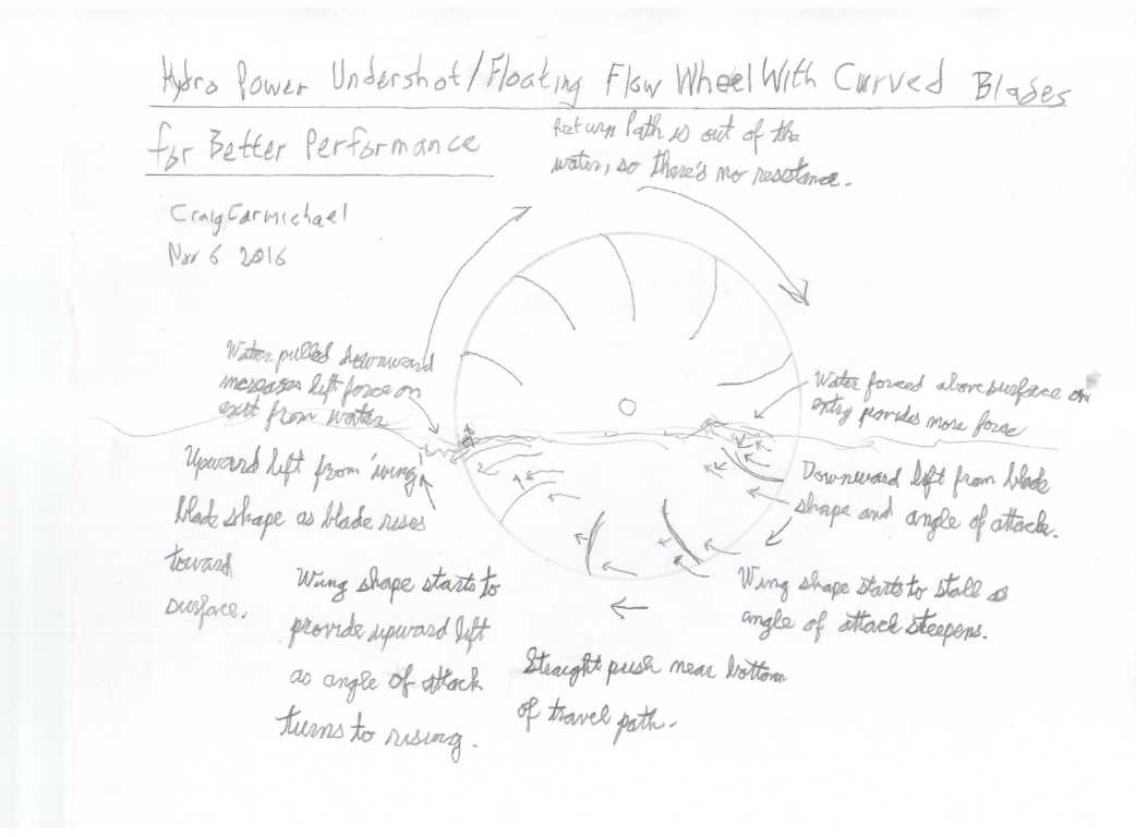
Then a new thought was that an 'airplane wing' blade
design
might be better, if the water is deep enough. In this case the axle is
placed near the water line, and the water in the entire deeper sweep of
the blades is utilized. If the wing is angled down as it enters the
water, ie upside down to an airplane's, it will have reverse 'lift', ie
it will pull itself downward. This is the direction it needs to pull in
this region to help turn the wheel. As it goes down to the bottom of
the sweep, it becomes more crosswise to the current and works like a
flat
paddle. As it continues to the back, the leading face becomes the top
face instead of the bottom. If the top is thus shaped like the top of
an airplane wing to provide lift in this direction, the blade will thus
lift upward until it reaches the surface.
The problem arises that what was the front of the blade is
now the back and vise versa. The airplane wing is thus going backward,
and won't work so well. It needs one shape entering the water and a
mirror shape exiting. Optimally it would have to be flipped end to end
under the water, the left and right ends changing places. I don't see
any practical way to accomplish that. So perhaps the simple compromise
would be to have a simple symmetrical curve, pointing at the axle like
the flat blade: "(". The inside of the curve would be up as the blade
enters the water. The wheel would be oriented with the axle above the
water just such that the front of the blade's curve hits the water
almost flat. This would provide minimal resistance and water would
"pile up" on top toward the back of the curve while the bottom still
has air under the back. The weight of the water as well as its momentum
would help drive the blade into the water. Then, the angle is good for
downward 'lift' until the stall angle (wherever it is), at which point
it's being pushed backward like the flat blade. As it approaches the
back, the angle becomes a lifting angle, again helping to turn the
wheel until it hits the water surface. There the water easily falls off
the convex slope of the back of the blade.
Thus, although at continually changing angles, the blades
have more turning force on the wheel at most points than a flat blade,
for as long as it is in the water, and thus can be more deeply
submerged, thus capturing the energy from the flow to a deeper depth,
with a substantially smaller diameter wheel and thinner individual
blades. But, unlike a vertical axis wind turbine with similar curved
blades, the return path, a little over 180 degrees, is out of the water
and presents virtually no reverse thrust to counter all the turning
force it got in the forward powered half. (Later in videos I saw this
curved "(" blade shape in use on a couple of waterwheels. So much for
it being "my" idea, once again!)
Whether such a refinement is warranted or advisable might
depend on the stream. If there's lots of water, the benefit probably
lies with making a slightly larger wheel and keeping the construction
as robust as possible. If one is scraping for every watt out of a small
stream, it could be worthwhile.
But other designs that might work better than a simple
wheel started to catch my eye, and then I got a whole fresh new idea.
A New Take
Watching some more youtube videos on the subject disclosed
a couple of other novel designs. One was a series of floating rollers
like a conveyor belt. The rollers were linked together and each one had
(at least) one or two flaps that opened up when it was in the 'down'
position to catch the water going by underneath. The weight of the
water going by drove them. One, operating in a spillway sized for it,
made good energy, up to almost a kilowatt. Another just floating in a
stream wouldn't even turn itself. I can hardly view the system as
robust and effective. I suspect they would quickly fall apart. Still it
was interesting.
Another system mounted on a floating vessel was pivoted
down to turn like a Darius "eggbeater" windplant rotor. It needed a
considerable depth of water. The symmetrical "wing" blades turned
faster than the water going by, and would be good for clubbing any
nearby fish. Still one can put a wire screen over (ie, all around) the
whole turning assembly to keep everything away from the moving parts.
A simple propeller unit might be better. At least the
blades are optimally shaped airfoils. Then there was the idea of the
Archimedes Screw, said to be the most efficient water flow catcher of
all, but it needed to be installed with a closely matched spillway
under it.
Somewhere in
seeing all those I got an idea for a new hybrid shape: something like a
spiral staircase, with each "step" being a propeller blade. (but with
two blades at each point instead of just a tread extending to one
side.) In that case, each blade could be the optimal wing shape and
angle of attack for maximum thrust. As I see it, water slows down as it
passes a propeller doing work, and so more flowing water would be drawn
in behind each propeller from outside the blade diameter, restoring the
flow between one propeller and the next one behind it in the
"staircase", so flow that went around the first set of blades would
enter the path for the next, and each blade would contribute thrust.
Thus overall thrust would be gained from a larger effective cross
section of flow than the area actually swept by the blades. The blade
diameter would be smaller, able to operate in shallower water than a
simple propeller of similar power, and the RPM would be highest. The
rotations might be geared up to an alternator in a single step. The
guard keeping fish out would have small cross section, albeit it would
be long front to back.
I'm somewhat concerned that the torque might tend to flip
the vessel over sideways. A wide enough but very light vessel might
find the tilt tending to tip until the turbine unit rises partly out of
the water. A simple solution might be to have two counter-rotating
"screws" side by side. This would also nearly double the power over
having one like-sized screw, without going any deeper, and still on a
single pair of floats.
Matched for example with the improved Piggott alternator,
any effective units could provide substantial continuous power from a
flowing
stream with little perceptible 'head'. Or it could do tidal flow power
for as long the current flows each tidal period. (Either of these
situations might be favorably employed in various locations on Haida
Gwaii.)
Some of the units in the videos were charging batteries. I
think when one gets a kilowatt or more of continuous power, this is
more of less a waste of time and an ongoing expense for batteries. A
kilowatt allows for a single heavy load like a stove burner. Better of
course is several kilowatts, allowing for whatever loads are required
at any given time. And once it's up to tens of kilowatts, it's not just
for one home.
Floats for
Floating Hydro Power Units
I have been (occasionally)
puzzling over how to make
good, simple floats for floating hydro units. The obvious choice is a
catamaran
design, and I have been regretting giving away two 8" x 10" x 12'
floats I made with a 'trimaran' boat project in the mid 1980s, only a
couple of years ago after keeping them stored under the house for all
this time. Advantages of the moored floating unit over fixed footings
are that it will go up and down with the water level, and that no one
can complain much about environmental impact since it touches nothing
solid and can be readily moved.
To make floats, aside from building what amounts to
a boat from scratch, one could perhaps buy plastic culvert pipes, fill
them with expanded styrene foam, and cap the ends. But the culvert
pipes are costly. It occurred to me one might do a compromise design,
easy to construct:
expanded foam insulation boards wrapped with a polypropylene-epoxy
skin. For small units, solid foam would be used with no air space
inside the hulls. That way, no sump pump would be needed as there's no
empty space to flood even if there's a leak. So here is the
plan for a small unit, just 8 feet long. The width can be varied with
the selection of cross pieces between the two hulls:
Buy four pieces of 2" x 2' x 8' styrene foam insulation
panels (2 per float), a piece of plywood, and PP+epoxy for the skin.
(Polyester resin
might work fine too? It's certainly cheaper.) Split two foam pieces to
2" x 12" x 8'. Glue the four pieces together with epoxy, making a solid
rectangle 12" tall x 8" wide x 8' long. Round off the leading edge to
decrease resistance as the water goes by. (A bow saw might be used for
quickly cutting off big chunks - or a long knife or other saw.) A
pointed front or a vertically curved one are possible shapes. Make two
for the two hulls. Cut two pieces of 3/4"plywood to the shape of the
top. Alternatively, cut 2" x 4" boards for it (heavier but stronger),
which would be epoxied together. Epoxy them to the tops of the hulls.
Wrap the PP skin around the hulls and epoxy it on. Perhaps tacks might
be used to hold it in place while the resin sets. Paint them to prevent
damage from the sun
over time.
Now we have two solid foam hulls with enough solid wood on
top to attach cross pieces, wheel and generator mountings, and mooring
lines to. The foam will float 1' (tall) * 8/12' (wide) * 8' (long) =
5.33
cubic feet * 62.3 pounds/ft^3 = 330 pounds per float, or 330 pounds
total
with 50% immersion. With turning forces on the wheel we want it
considerably lighter than that, but I can't see it not being good for
150-200 pounds of wheel, generator and miscellaneous parts. Then there
will be cross pieces, mountings and fittings.
The two counter-rotating spiral turbines idea should give
the most "bang for the buck" in a shallow tidal channel, creek or
river. Or if using 'paddle wheel' designs with curved blades, one might
use two (or even three) small diameter wheels, front
and rear, and two generators, even on such a small set of floats.
Multiple
outputs could be rectified (or diode isolated for DC generators) and
fed to shore on a common 2 wire cable.
One might want mesh guards under the water to keep fish
away from the blades. (Especially if the blades are delicate - never
mind the fish!) And maybe strong "roll bars" underneath to
prevent the blades from hitting the bottom if the water gets too
shallow... yes, that would be a good precaution in many situations, or
even just to prevent blade-bending accidents during deployment.
Better than the "roll bar" might be for a long "ski" to
run from front to back on each hull, extending below where the
propellers will turn. If the water becomes too shallow, the unit will
simply bottom out resting on its skis and keep working until too much
of the propeller (or paddle wheel) is out of the water. The fish-safety
mesh would extend between the skis along the whole length, and from
each ski to the hull to cover the sides. Another mesh would cover the
front, but the back could probably be left open. (I do have a concern
about the mesh getting clogged with seaweed or debris. Well, that's a
reason for trying out small prototypes before going large!)
For a pilot project, I noted another location in Haida
Gwaii where tidal flow power might be employed, this time on a small
scale for instead of the largest for major power. The Delkatla slough
at Masset is a tidal marsh and nature sanctuary fed through a channel.
It passes under a bridge near town as the narrowest point. Thus it is
near road and power lines, and a small floating unit would be seen by
people who could note its small environmental footprint... and perhaps
hear the hum of electricity being made. Before connection to the grid,
it could light a bank of incandescent bulbs. That should at least be a
good demo.
http://www.TurquoiseEnergy.com
Victoria BC Canada