Turquoise
Energy Ltd. News #107
covering December 2016 (posted January 6th 2017)
Victoria BC
by Craig Carmichael
www.TurquoiseEnergy.com
= www.ElectricCaik.com
= www.ElectricHubcap.com
= www.ElectricWeel.com
Month In Brief
(Project Summaries)
- HAPPY NEW YEAR! - Solar PV Price Continues Dropping - Making Improved
Piggott Alternator - Piggott Unipolar BLDC Motor? - Air-Nickel Battery
Experiment - Electric Suzuki Swift Notes - Moving To Haida Gwaii -
Sustainable Energy Courses and Enterprise?
In Passing
(Miscellaneous topics, editorial comments & opinionated rants)
- The Bottom Line: the Core Values - The War on Free Speech - A Broader
Perspective of
Economics - Cartoon: Trickle Down Economic Theory Explained
- In Depth
Project Reports -
Electric
Transport - Electric Hubcap Motor Systems (no reports)
Other "Green"
Electric Equipment Projects (no reports)
Electricity Generation
* Building Improved 1500-4000 Watt Hugh Piggott Frictionless Axial Flux
Alternator
Electricity Storage - Turquoise Battery
Project (NiMn, NiNi, O2-Ni), etc. (no reports)
December in Brief
HAPPY NEW YEAR!
While my time is increasingly occupied with moving to
Haida Gwaii, I did get some work done. I stopped cutting gears, at
first hoping some more 5/8" UHMW would appear in the bins at Industrial
Plastics. Then I tried to order some and was given a ridiculous price.
I suppose I can turn some 7/8" UHMW thinner on the lathe since I have
lots of that. But it got too cold to work outside, and the shop was
pretty cold too.
I ran a nickel-air battery chemistry test. It seemed to
work with oxalic acid for electrolyte, but I ran into the same problem
with heavy self discharge as with every other cell I've made of any
chemistry. It can hardly be anything but the graphite in the positive
electrode. They have similar problems in fuel cells. Perhaps I should
try making some of that osmium doped acetaldehyde again to paint on as
an electron-passing boundary layer.
I also got some work done on an improved Piggott
alternator. I'd really like to make something that I'm sure will
actually work in a short time, and at least the Piggott alternator is a
design known to work. I see no special problems in building prototypes,
and they should be useful. The uncertain part is how much more power it
will be able to handle than the original design. I'm expecting at least
2000 continuous watts instead of 500, at 1000 RPM instead of 280, and I
really hope it will be as much as double that, 4000 W, which would
probably be at around 1414 RPM. (A DC to DC converter with a wide input
voltage range is doubtless your friend when dealing with unknown or
variable generated voltages, eg from wind power.)
Solar PV Price Continues Dropping
I make note of an article saying that solar photovoltaic
power, which dropped below the cost of nuclear plants for new
installations in 2010, on average, has become the world's most
economical source of new electricity this year. A price of
2.6¢/KWH was mentioned in the article. I am amazed to find that a
solar panel - a large piece of tempered glass in an aluminum frame with
light sensitive materials pasted to the glass - costs less than a
similar piece of framed glass would from a glass shop even without the
solar collector. They still only work when the sun is shining and are
least cost effective of anywhere here in the cloudy Pacific Northwest
[of North America].
But I should also remind that the potential of VHE ray
energy (or 'lambda ray' or 'short space ray' energy, also perhaps
explaining what is vaguely termed "zero point energy") striking the
Earth apparently far exceeds that of solar visible light rays. The
collection devices are compact with apparently immense energy
collection potential, as the rays rain down on our planet day and
night, probably in varying amounts from different directions. A number
of people have harvested this energy, notably (but not exclusively)
Thomas Henry Moray in the 1930s, Steven Mark perhaps in the 1950s to
1970s, and probably Nicola Tesla near the start of the 20th century.
What remains is to understand these rays and the process
of converting them to electricity better, and to come up with reliable
designs that can be replicated. Mark came close to that or perhaps
accomplished it, but his work appears to have been strongly undermined
(so was Tesla's and Moray's). He made a number of working "Toroidal
Power Units" first using vacuum tubes, then transistors (along with
some that didn't work), and explained the operating principles, but no
complete circuit diagrams and plans have come to light so far. However,
he did explain the operating principles. I have written various
articles about this energy source which I hope may be found
illuminating in previous Turquoise Energy News issues, # 69, 70, 71,
84, 92, 94, 95. There is probably enough to go on in those articles to
create working units, but somehow I myself diverted to other exciting
projects - always intending to get back to this.
Making Improved Piggott Alternator
The main thing I worked on in December was the improved
Piggott alternator, begun in November with taking a rotor design to
Victoria Waterjet to have 4 rotors cut from 1/4" steel. I ended up
redoing the rotors in LibreCAD and e-mailing the .DXF file. That seemed
to be a good move because the rotors were done two days later.
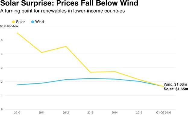
 One of the rotors showing a supermagnet, and
the
way the magnets get strapped on securely,
One of the rotors showing a supermagnet, and
the
way the magnets get strapped on securely,
with the straps being epoxied into place.
 There are several options for attaching the
rotors to a shaft, including SDS taper-lock hub, weld-on hub,
There are several options for attaching the
rotors to a shaft, including SDS taper-lock hub, weld-on hub,
and the original Piggott car or trailer wheel hub mounting techniques.
But it turned out that all the extra
option holes added considerable cost to the cutting, so I'll probably
reduce
the options to those I use.
I spent more time on the stator design. I got as far as a
mock-up but didn't wind the coils or cast them into place in epoxy
(with polypropylene reinforcement pieces).
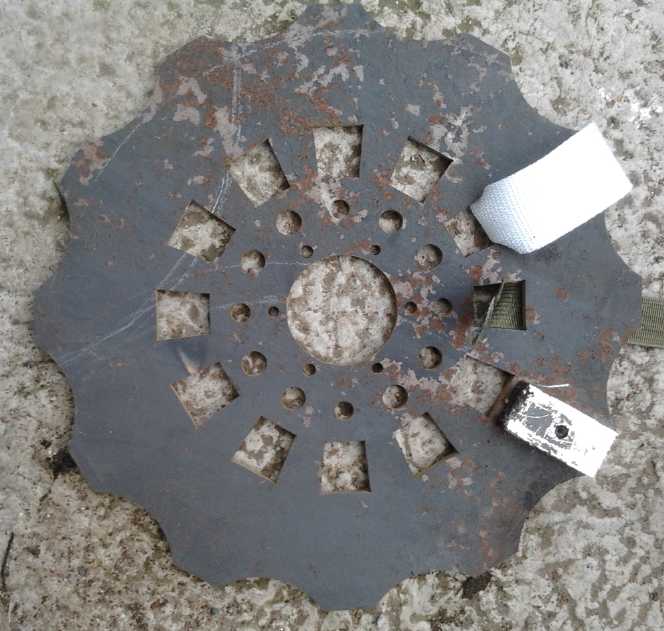
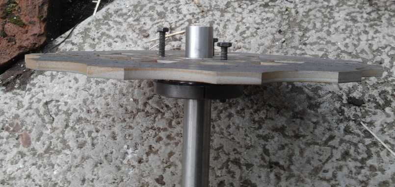
 Mock-up of the stator (~14" O.D.) on top of the
paper drawing of it.
Mock-up of the stator (~14" O.D.) on top of the
paper drawing of it.
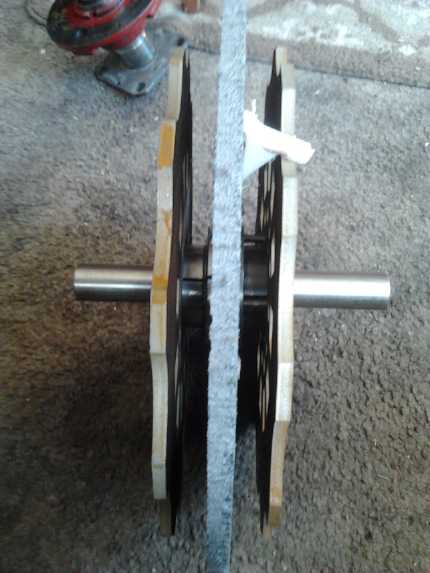 This shows the essential planned configuration
with the two end rotors outside and the thin (1/2")
This shows the essential planned configuration
with the two end rotors outside and the thin (1/2")
stator between. The rotor magnets face the stator with a 1/8" gap to
the coils.
Bearings hold the shaft to the end plates/bells while the stator is
attached to the outside case rim.
This makes for a very short machine compared to its diameter, but I'll
leave extra length to fit three
rotors with two stators, or even four rotors with 3 stators.
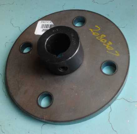 For such extended designs, the inner rotors
will be thin and cast in epoxy.
For such extended designs, the inner rotors
will be thin and cast in epoxy.
The two faces of each magnet will face a stator on each side.
The hub and rotor above were purchased to be a solid center for such a
rotor.
Bolts or threaded rods through the four holes, which match those of the
outer rotor,
may be used to adjust the exact gap between rotors.
Finally, I got some clear lexan (polycarbonate) sheet to bend into a
cylinder to make a transparent outside case rim from, and a round piece
of aluminum for one end.
Piggott Unipolar BLDC motor?
Here's an
interesting development in unipolar BLDC motors: When I made the first
one, the unipolar version of the "Electric Caik" motor, I was
disappointed by the performance. It ran, but the torque and the RPM
were low. It didn't seem to be wholly the fault of the unipolar
motor controller. I think it was because with two like coils facing
like magnets, the magnetic circuit is less effective than having
opposite polarity coils active at the same time. Then I thought I would
just change the magnets on the rotor so that the stator could have
opposite polarity coils in the same phase on opposite sides of the
rotor. After trying out several
designs I started to realize that no matter how it was designed, at
some point, the wrong polarity coils and magnets would line up and it
would try to turn backward. Apparently it just wouldn't work however it
was done. I then started work on the ARM unipolar reluctance motor
instead, where the steel would be attracted to the coils regardless of
polarity. (That was less robust than I had hoped, too... maybe it
really is the motor controller?)
Somehow I started thinking on the 27th that if at each
point on a BLDC motor there was both a north and a south magnet,
perhaps like a horseshoe magnet, at opposite ends of the coil, it would
solve the problem. There should be powerful interaction, all in the
same direction, at every point around the circle. I started trying to
figure how that might look. A transverse flux design, perhaps? But one
idea I came up with was two
rotors and a stator with coils in the middle. And of course, that was
exactly what I was already building in the Improved Hugh Piggot
Alternators project. All it would need would be Hall or optical sensors
added to tell a motor controller where the rotor magnets were in their
rotation. Apparently two seemingly separate projects might well be
merged into one.
If the air core works as well at low RPM.s when it's run
as a unipolar BLDC motor as it seems to as an alternator, it would be
great! With
no iron losses, efficiency could probably approach about 97%.
Otherwise, since
the air core in the alternators is in fact air, if the performance
isn't all one might hope for, I might consider inserting some metal
pieces and seeing how that changes the performance. If it seems
promising, I could perhaps fill in the air spaces with an epoxy mixture
of iron or (soft magnetic) steel filings/powder. This would of course
make the motor behave quite differently from the air cores alternator.
Air-Nickel Battery Experiment
I figured it was high time to get back to this, and try
using oxalic acid for electrolyte as mentioned 2 or 3 months ago. While
lighter elements dissolve in most common acids, I long ago checked out
some acids on line and found that nickel, nickel oxalate and nickel
oxide/hydroxide (along with zinc, zinc oxalate and zinc oxide) don't
dissolve in oxalic acid. Thus one could have a nickel-zinc acid battery
instead of a lead-lead acid battery [has forms of lead in both
electrodes],
which would have a much higher energy density. One might also do a
nickel-nickel acid battery.
On the 11th I took the long dried out air-nickel cell and
immersed it in water to dilute out the potassium sulfate salt, changing
the water 4 or 5 times over a period of hours.
I mixed a little oxalic acid with water and wetted a new
piece of separator paper. The cell seemed to charge (~~10mA), and the
voltage went up to over 1.5, but it quickly dropped under volt when
taken off charge. I added a bit more water around the edges and the
charge voltage dropped below 1.5V. Gradually it seemed to settle around
1.7 to 1.8 volts. Why couldn't it handle lots of current? Solid nickel
and nickel felt should be good for many amps, and so should the carbon
fiber. It had to be either the oxygen reaction or the electrolyte was
far too slow.
As I monitored the cell over a few days, the time it took
to drop below a volt gradually got longer - probably the
carbon/graphite fiber was gradually oxidizing. The rate of drop near
1.0 volt went from one millivolt per 3 seconds to one per 4. If it
didn't keep losing, it would probably settle at just over a volt - 1.05
or so. The worst problem with measurements was that the cell was
continually drying out. Adding a few drops more water always helped the
charging, but sped up the self discharge.
After a couple of weeks it stopped improving and I gave it
up for the time being. The self discharge has been similar with every
cell I've made of whatever chemistry, so it must be the graphite in the
positive electrode. I have a couple of things to try to solve that when
I have time.
Electric Suzuki Swift Notes
One advantage of DC permanent magnet motors is that they
have full torque even from a stop. I've had no trouble with the Swift,
but one does note the sluggish starts. With the pedal pressed
considerably down, the current starts at only about 60 amps and then
rises rapidly with speed. I had thought it might well be geared a
little higher so it could go faster on the highway than 80 Km/hr. But
one day carrying a heavy load, starting from a traffic light up a hill,
the car barely seemed to start moving. Once it was going a few
kilometers per hour it was fine, but for a couple of seconds I wasn't
quite sure it was going to get there. Perhaps it was fine, but I now
feel gearing it higher (ie less reduction) is out. It seems like a good
place for a variable transmission!
On the other hand, AC motor controllers seem much less
prone to failure than BLDC controllers, in spite of having the same
coil driving transistor arrangement. This would probably be because
they don't supply the high currents required for high torque until the
motor is spinning and cycling nicely through the phases, instead of
being stuck on one phase for a time with the motor struggling to start
moving.
I opened the battery compartment to remove the 32 - 100AH
lithium batteries and return them. But it all looked so neat and
orderly, well designed and installed, and they all fit in the
compartment made for them. I had enough lithium and nickel-metal
hydride batteries to replace them, but did I really want to make a
project of this when it already worked well, and then have bulkier,
somewhat heavier batteries and chargers filling half the cargo space? I
put the cover back on and e-mailed the previous owner who had given me
the car on condition that I return the batteries. I offered him 5000$
for the batteries, to be paid after I had the money from selling my
house. This he accepted.
Moving to Haida Gwaii
Of course this is the most exciting project and highest
priority from my point of view. Doing it at this point in time seemed
opportune as there is what I consider to be a huge housing price bubble
in Victoria BC at the moment, driven up by investment demand. Such
bubbles end suddenly: Prices stay up for a while after sales, at some
point, rapidly dwindle in the overheated market. Sales only resume once
owners drop their prices sharply. But one's liabilities don't drop with
house prices, so they become a far larger percentage of one's personal
balance sheet. "Sell high" it seems can apply to homes as well as other
investments... but only if one can buy elsewhere, in a place one would
like to live, for a lower cost. Despite the latitude, Haida Gwaii is
still in the mild coastal climate zone.
My 20 foot long "sea can" steel box shipping container
arrived in the yard and I started filling it, then rather unexpectedly
my house sold for a good price. It wasn't listed yet as I hadn't
cleaned it up yet for viewing, but my agent put out word and a
developer bought it anyway. And it turned out to be the same developer
who had turned the house across the street into 4 very nice townhouses,
with the original house as the front one, in 2000.
The house I had hoped to buy in Tlell finally went from
"sale pending" to "sold" in the real estate listings. I couldn't see
buying the place I had originally looked at with 3 small dwellings and
no main house on it, and so my vain hope for getting a place at a
really economical price vanished. I may have been only days too late,
after the owner said he'd had it on the market for 12 years. I bought
the only remaining prospect on the east coast of Graham Island, a very
nice house at Lawn Hill 16 Km to the south. I had only happened to see
its "For Sale" sign at the highway as I drove by to explore the south
end of the island, and I only looked at it briefly from the outside,
thinking it would be too costly for my budget. Fortunately I had
snapped a picture of the For Sale sign with the phone number, as it
wasn't listed anywhere yet. (Also a
couple of other pictures and short videos. Later it appeared on
HaidaGwaiiTrader.com and I could have found it again. By then I was
buying it.) But it was still only 1/2 what I sold my Victoria house
for, and I should have at least some net positive balance left over
when the smoke clears and all is paid off.
It was probably a blessing. The other house would have
needed considerable work. As someone said, it was a "fixer upper".
(OTOH, I would have had lots of money left over to hire people to do
the work I didn't want to tackle myself.)
The Lawn Hill house was already fixed up to a good
standard by the owners, the heirs to the estate, who also lived nearby.
That would leave me free to quickly return my efforts to green energy
projects and ideas for political and social improvements. And better
yet, it had a huge shop, 24 by 24 feet, with a garage next to it. And
it had a substantial stretch of waterfront on Hecate Strait - a perhaps
even more ideal situation for trying out ocean wave power than the
first property I looked at months ago.
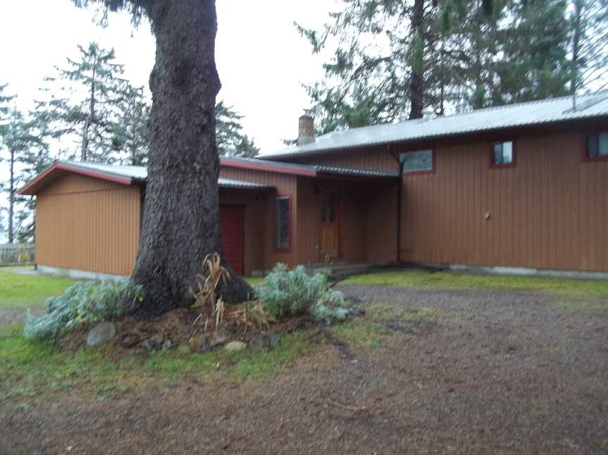 Lawn Hill house - north side from driveway.
Shop is to the right of the picture;
ocean is at left beyond fence and trees.
Sustainable Energy Courses and Enterprise?
This will be an ideal space to set up shop and work on
green energy projects, including electric vehicles. And I plan that it
would also include running green energy building workshops and then
hopefully getting together a small group of builders to work at
transitioning the Haida Gwaii islands from diesel powered electricity
to sustainable sources: flowing water, wind, and wave power. I think
the type of smaller installations planned, with floating generation
units and quiet wind power without external moving parts as described
in TE News #106, will meet with rapid community acceptance.
I intend this to be a self sustaining, if somewhat slow
payback, enterprise. People may contribute their time, locations on
private lands where power is available, or money. "Net metering"
regulations allow property owners to connect power to the electrical
grid and sell the electricity.
The proceeds of these sales will be distributed as fairly
as may be determined, between builders and other time contributors,
those who finance the projects, and home owners. Perhaps the new
"contract theory" techniques worked out in recent years by the 2016
Nobel prize winning economists can be employed in helping to assess
fair terms and options for each party. Of course the proceeds will be
small at first, but they will be ongoing and will increase as more
installations are completed.
When a good level of experience with small installations
has been achieved, larger production facilities would be obtained and
larger but otherwise similar projects may be undertaken with direct
"Private Power Producer" contracts with BC Hydro, such as the "Juskatla
Narrows" tidal flow project. (On one scanned map I found on line, I
could see that this channel had a name, but it was utterly illegible.)
At some point, the islands' diesel generators may be turned off in peak
production periods, later in average periods, and finally most or even
all of the time.
The next 3 or 4 months may have little project news as
I'll be occupied with moving. I may even skip an issue or two.
In Passing
(Miscellaneous topics, editorial comments & opinionated rants)
The Bottom Line: the Core Values
When one speaks of the "bottom line", it is assumed to be
a desired monetary outcome - income or profit. But is money not merely
a means to an end? What is that end? Implicitly, it must be that money
is assumed to bring about a better quality of life, with a better
environment for growing into one's potential. Again, a secondary value
has been substituted for the primary ones, implicitly assuming that
they will be enhanced thereby "by osmosis", while not actually
acknowledging them.
But of course in empathy and love, we must agree that
others should have equal opportunities to achieve a good quality of
life and to grow into their potential. When some have achieved
accumulated "bottom line" wealth far beyond their capacity to make
productive use of it, and collecting more and more has become merely a
game while countless others are in want, they have ceased to be living
up to their growth potential and have become mere
materialists. Better that they should play the "Monopoly" board game
where no
one is hurt and resentment is superficial and short lived.
The Real "bottom line" then is the core values of social
sustainability: Quality of Life, Growth, and Equality. Focusing on
monetary gain instead creates misplaced priorities and misallocation of
resources, which unfailingly retard personal growth and improvement,
and sidetrack society from learning and serving the ever evolving needs
of a continually changing society and planet.
And overpopulation too puts pressure on all aspects of
society. The inequality of opportunities between nations as well as
individuals within nations is magnified, and when life in some nations
is bad enough, vast populations start to move and seek a better life in
lands where there has long been more opportunity, stressing them too,
perhaps to the social breaking point. As the mayor of Palermo, Sicily
said a year ago of the influx of refugees, "Palermo is no longer an
Italian city."
The War on Free Speech
People who have nothing of note to say that might
criticize the "powers that be" or threaten the profit line of large
corporations might not understand that in the traditional media -
newspapers and broadcasters - real journalism, at least in the
political and economic realms, has vanished. Virtually all the major
news media have come under the ownership of about half a dozen people,
who are interested only in profit and who would never publish a story
that might upset or offend their advertisers. Nor would they publish
one that might upset or offend the government. With the one they risk
losing revenue; with the other, their broadcasting or operating
license. With the passing decades pass they have finally come to
represent only the interests of the powerful - of corporate America or
even the global corporatocracy, instead of being critical voices of
truth questioning what is happening in the world around them. They have
thus become propaganda for a corrupt "status quo" of powerful
established interests which resents attempts at social corrections and
progress, rather than a voice of truth, pleasant or unpleasant, so
badly needed for democracy to function.
Only when one decides to publicly and loudly say or do
something that doesn't fit into the establishment narrative is he
surprised to discover that he comes under attack for saying it, that
the "powers that be" not only hate free speech being delivered to the
public but will go to considerable lengths to squelch it and threaten
those who speak it.
In recent years the media has shown that they will tell
all manner of lies - not even just exaggerations any more - and parrot
them over and over, based for example on unverified blogs posted by a
dubious individual even with an obvious agenda and transparently false
narratives, if it fits their agenda.
One such 'blog' that made the mainstream news circuits was
an article with a photo of "Russian tanks invading Ukraine" after the
coup there violently overthrew the democratically elected government,
in similar manner to many other foreign sponsored coups, and such as
was recently attempted unsuccessfully in Turkey.
And that's another example: When did a democratically
elected Turkish president and parliament, with a structured national
legal system, 'staunch ally of the USA and the west', become "Erdogan's
tin-pot dictatorship" as the western media suddenly and repeatedly
started referring to it in advance of the coup attempt?
And how many times were we told unequivocally that Iraq -
at the time quiet for over a decade - had unspecified "weapons of mass
destruction". There were never any specifics and no evidence was ever
presented, but somehow this justified invading and occupying the
country, where no such weapons were ever found.
A more recent example would be the framing of Donald Trump
as a madman and a prejudiced bigot.
But with the rise of the internet the "alternative media"
- home of today's real investigative journalists and truth seekers -
can now publish for themselves on web pages and on youtube without
having to go through these sources of propaganda. Thus the truth, if
not broadcast, does start 'leaking out' in plain view for those who
want to search for it, exposing the egregiousness of the lies being
promulgated by the bought propaganda media.
Someone recognized the photo of Russian tanks in Ukraine
as one having been taken during a joint Russian-Ukrainian military
exercise in 2008. The tanks were there, on Ukrainian soil, but in full
participation with the Ukraine government. But the absurd narrative of
"Russia has invaded the Ukraine" continued to be pushed. Corrections or
apologies for such reporting "mistakes" even when exposed are rare and
are given little publicity. How likely is it that Russia could be
"invading the Ukraine" for a couple of years now with no violence
except in territories where Russian speaking people live, and without
having achieved any military objectives? Russian president Putin once
said that if Russia invaded Ukraine as was being reported in western
media, they would be in Kiev in a week. He has repeatedly insisted that
negotiation is the way to attain lasting peace in the Ukraine.
And how is it that soon after the American media started
tarring Turkey and Erdogan with a black brush, Americans including a
general were found to be in the forefront of the attempted coup? Did
that make the western news?
And if the stories about Trump were true, why did so many
latinos and blacks publicly rally behind him? Why did none other than
the
reverend Jesse Jackson once praise Trump for his long time support of
the black community? Someone dug out a tape of this "Thank you" speech
from about 1998(?) and it was aired on youtube news channels. Ah, but
not in the corrupt mainstream. The pictures of the Trump-supporting
blacks, latinos and women, holding up their signs "Blacks for Trump"
and so on were never shown in the media that only wrote story after
story smearing him. Trump didn't win the election without widespread
support from large numbers of Americans.
The damage done to those on the receiving end of these
defamatory "news" stories is immediate and lasting. It takes time and
energy
to prove that claims repeated over and over by a chorus of loudly
croaking frogs are untrue, and even when it happens, the same media
will give it no publicity, leaving the manipulated public perception
unchanged. The court system, even when people do try to take them to
task and sue the media for slander, is far too slow and public
perceptions have already been permanently altered.
Thus we saw the most highly polarized election ever, where
those who simply read the New York Times and watched the same broadcast
stations that used to tell us what was going on in the world, could not
understand why anyone would ever even consider supporting Trump and saw
Hillary as a moderate and a strong leader. On the other side, those who
listened to Clinton's own selected words as reposted on youtube by
those with a different and perhaps less biased agenda, heard her say
opposite things at different times and to different audiences, of
suspicious deaths of Clinton opponents, of "Pay for Play" diplomacy in
her time as Secretary of State and that the Clinton foundation "is the
world's biggest charity fraud" and was used to launder the money, and
didn't see how she could be trusted to lead the nation, while Trump's
speeches at least showed him to be more of a real person with values he
actually seemed to stand for, instead of just a figurehead for a
shadowy
"corporatocracy" that ruled with stealth and anonymity from
behind the scenes.
And now these purveyors of fake news and lying propaganda,
in collusion with the powers behind the government, presume to label
all alternative sources of real news and other views on the internet
and on youtube, as "fake news" and as "knowing or unwitting mouthpieces
of Russian propaganda", and have made up lists of them. They are trying
to have them eliminated as being "inappropriate" from searches on the
web or on youtube so that no one will find them. They are trying to
have youtube flag them as "not advertiser friendly" so they can't make
any money from "monetizing" their youtube videos, which brings some of
them a pittance that allows them to operate. Yet many in the
alternative media give links to their sources, while the 'mainstream'
media simply expects us to believe, even while neither giving nor (if
pressed) having any credible sources for many of their tales.
People in increasing numbers are gradually seeing through
the hypocrisy and lies they are being fed day to day. Readership and
viewership keep dropping and it's not all attributable to the internet.
One person said that he tried to watch a mainstream news program, but
the very first sentence contained 3 or 4 false assumptions: that
something was being hacked (no evidence), that it was by Russia (no
evidence), and (wholly unrelated to the subject) that Russia had
invaded the Crimea. (Russia already had naval bases with troops there
by agreement with Kiev, and the Crimean people of all stripes
peacefully voted over
90% to rejoin Russia rather than acquiesce to being led by usurpers who
had staged a violent coup in Kiev.) The assumptions could thus be
easily refuted - had already been - but so what? Anyone allowing
themselves
to be bombarded by such trumped-up "talking points" statements day
after day is bound to evolve a distorted view of world affairs.
The next logical step might be to start eliminating, one
way or another, all the people presenting all other news, other views
and other opinions than "the narrative", such diverse people as Gary
Franchie, Greg Hunter, Alex Jones, James Corbett, Kerry Lutz, Elijah
Johnson, Max Keiser, Tyler Durden, Ron Paul, David Quintieri, and so
on, and perhaps some of the finance and political analysts some of them
frequently interview like Bill Holter, Alasdair McCloud, Peter Schiff,
Andy Hoffman, Dr. Paul Craig Roberts, Rob Kirby, and so on. If this
starts happening, we will know the behind the scenes rulers are
desperate to the ultimate degree to keep truth and free speech away
from the inhabitants of this planet, from "losing control of the
narrative".
"Those who make peaceful revolution impossible make violent revolution
inevitable." - US President John F. Kennedy, 1960-63
But such a program cannot succeed for long. In helping
those "behind the scenes" to change their
minds and realize they are part of a broader society that is
worthwhile, and in wresting control from those who simply will not
co-operate, violence must not be a tool. Violence only eliminates
possibilities for peaceful, democratic change and leads to
dictatorships. But this is already
recognized by large numbers of people, especially in North America and
Europe, and we may hope for good results eventually. For the present
the economy will continue to worsen. Politics must continue to evolve,
and the ideals and ideas for creating socially sustainable institutions
and people need to be spread and disseminated.
A Broader Perspective of Economics
Someone pointed me to the interview linked below. This is
one of those times where one recognizes that the discussion, in this
case of both the interviewer and the interviewee, goes far beyond the
perspective of the 99%, and even with little familiarity with the
subject, one recognizes voices of experience and long study of the
subject and its history - of true expertise; of genius.
Hudson and Keen point out how the current day financial
system, and education on economics and finance, is based on incomplete
assumptions and theories that add up to unreality and the absurd,
unrepayable debts: a transfer of wealth from an increasingly
impoverished 99% to an ultra-rich 1% of parasites on society. Either
the real economy or the banks can be saved, not both, and governments
have chosen to save the banks.
http://michael-hudson.com/2016/11/keen-hudson-unpick-historical-path-to-global-recovery/
At the end Hudson notes that the odious and unrepayable
Greek debt that is destroying Greece is sitting as credits in a very
few peoples' Swiss bank accounts.
Sometime I would like to see more of his work.
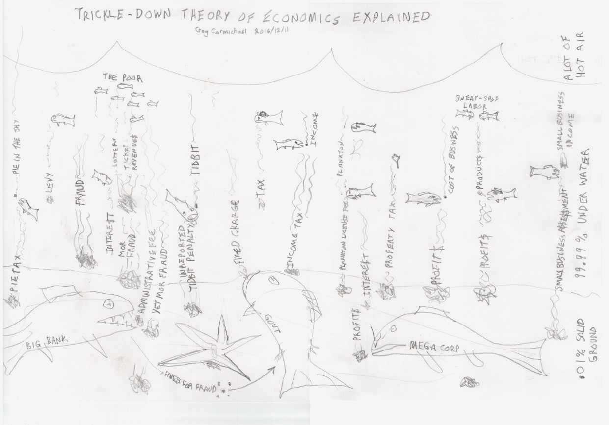
(Now it hits me that my own cartoon below strikes at the
gist of this very matter. And I did it before I read the interview!)
Having all the wealth flowing in one-way paths without
returning can now only develop into an increasingly serious global
economic depression or crisis. It's not that the problems aren't
understood or that solutions aren't known. But in the absence of
socially sustainable governing and economic institutions, no one in
leadership positions seems to have any stomach for doing what needs to
be done to change course.
Funny or Not
My brother's address in Toronto is 2 Martini Drive. With
the crackdown on drunk driving increasing to absurd proportions, I am
afraid one day he'll be arrested for drunk driving while sitting at
home watching TV.
There seem to be misconceptions about "Trickle Down"
economic theory, and I thought I would set them straight in this chart.
Newsletters Index/Highlights: http://www.TurquoiseEnergy.com/news/index.html
Construction Manuals and information:
- Electric Hubcap Family Motors - Turquoise Motor Controllers
- Preliminary Ni-Mn, Ni-Ni Battery Making book
Products Catalog
(Will accept BITCOIN digital currency)
...all at: http://www.TurquoiseEnergy.com/
(orders: e-mail craig@saers.com)
Electricity
Generation
Improved
High-Powered Hugh Piggott Frictionless Axial Flux Alternators
STATOR
On the 10th I
drew a diagram of the stator as I wanted it
and bought some 7/16" UHMW plastic to make parts of the mold with. (It
was a large UHMW plastic breadboard at a kitchen place -- for 1/5 of
the price "Industrial Plastics" wanted for 1/2" sheet UHMW.)
On the 11th I started making up a spreadsheet with the
G-code commands the CNC drill router would use to cut out the mold
pieces. There was really only one aspect, 9 "humps" in the outer edge
for bolts, that had any trigonometric spreadsheet calculations in it.
Somehow I got them right on the first try.
Between (a) the thin stator casting just covering the
wires, (b) the air core centers being actually air rather than cast
resin, and (c) the outer edge of the coils between the "humps" being
also an air space near the coils, the epoxied coil wires are surrounded
by cooling air except for the sides where the epoxy cast between the
coils holds everything together. Together with the rotor magnets
circulating air around through the case and back out as the rotors
spin, that should make for the best cooling of the coils and hence the
highest potential power handling capability - far higher than the
original Piggott design.
On the 13th I made the center mold from the 10mm thick
breadboard. Leaving enough stiffness around the outside, it needed
pretty much the whole 16" x 20" board. (I could have cut 2 or 3" off
one end.) The router bit cut like a butter knife and left a very rough
edge with shreds of plastic glued (melted) into it. It must be really
dull. I had to cut the crap off with a knife and then file it all
somewhat smooth. Not exactly the polished, non-stick surface one wants
for a mold. (Add new router bits to shopping list.)
The inside and outside pieces came out okay. My plan for
the coil centers was to have the router cut them from the ring of waste
material in between. But the first couple overlapped the edges and came
loose. The third one seemed okay, but I had done it in the wrong order:
cut out the pieces and then drill two holes in them. Of course the
pieces were cut loose, and the third one got one in the wrong place and
the router picked it up and spun it around at high speed. I had to shut
the machine off.
I decided to change the shape anyway as they were a bit
too long. They didn't quite leave the required 3/4" inside and outside
for the wires. I had another partial piece of the same breadboard, left
over from some earlier mold, to cut more from.
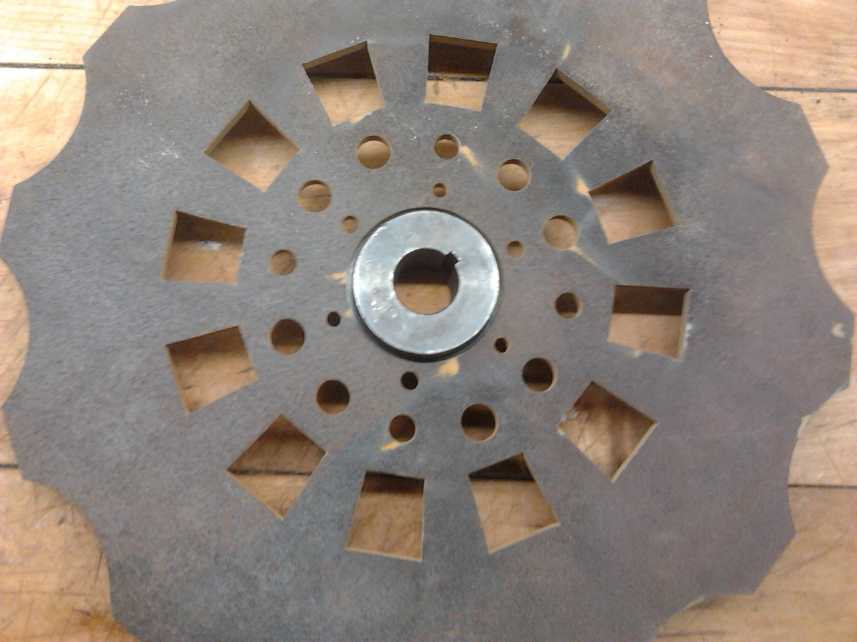
 Then I did a reality check with a disk brake rotor and
found I had drawn the center area wrong. The 100mm spacing in small
vehicle studs with 4 bolts was between opposite holes, not adjacent
ones. I could easily take 30mm off the inside ring diameter. I decided
to do so. Notwithstanding that would put thick epoxy along the inside
edges (not good for heat dissipation), there was so little epoxy in the
casting where the coils were - basically only what was squeezed between
the wires - that I was concerned about strength. This would give one
solid edge. Rather than the CNC, I could turn down the inner disk I'd
already made on the lathe. The outside edge would be smoother, too.
Another thought was to turn down only 1/2 the width. Some cooling air,
some strength. And I couldn't do that on the CNC! The disk, which I
didn't have a very satisfactory lathe mounting for, wobbled in the
lathe, and I gave up that idea. For now.
Then I did a reality check with a disk brake rotor and
found I had drawn the center area wrong. The 100mm spacing in small
vehicle studs with 4 bolts was between opposite holes, not adjacent
ones. I could easily take 30mm off the inside ring diameter. I decided
to do so. Notwithstanding that would put thick epoxy along the inside
edges (not good for heat dissipation), there was so little epoxy in the
casting where the coils were - basically only what was squeezed between
the wires - that I was concerned about strength. This would give one
solid edge. Rather than the CNC, I could turn down the inner disk I'd
already made on the lathe. The outside edge would be smoother, too.
Another thought was to turn down only 1/2 the width. Some cooling air,
some strength. And I couldn't do that on the CNC! The disk, which I
didn't have a very satisfactory lathe mounting for, wobbled in the
lathe, and I gave up that idea. For now.
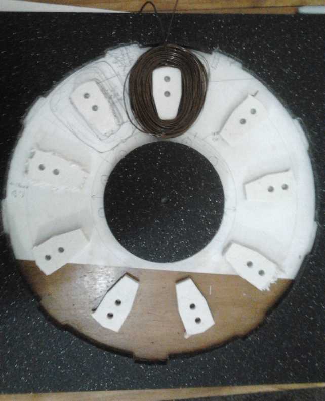
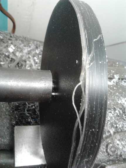
Turning down the inside piece, using the center
mount with
pins I had made recently for holding small plastic gears.
And I phoned to get the cutting of the rotors stopped
before they were cut wrong. Lucky they were taking so long getting
around to it! (But when I retrieved them, it turned out I hadn't made
the mistake on the rotor drawings.)
On the 17th I got another 1/4" router bit and cut out nine
more coil winding forms. I discovered the old bit seemed perfectly
sharp. The difference was that at 10,000 RPM it cut fairly cleanly but
seemed a bit jittery, so I had turned it up. However at 13,000 RPM it
melted the plastic and left it with the melted-in waste and very rough,
melted edges. To my chagrin, my belt sander hardly ran. Probably it
needs a new drive belt. Why are so many things going wrong just when I
have so much to do?
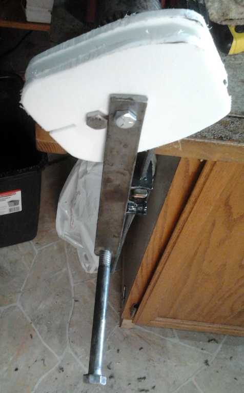 I cut a couple
of outsides for the coil winding on the
bandsaw and drilled the same 2 holes as on the routed inside pieces.
The winder handle on the center bolt butted against the second bolt and
couldn't come loose and turn without turning the coil, solving an
annoyance of all my previous coil winders, which had to be strongly
tightened down with a nut before use, and even then the handle
sometimes slipped.
I cut a couple
of outsides for the coil winding on the
bandsaw and drilled the same 2 holes as on the routed inside pieces.
The winder handle on the center bolt butted against the second bolt and
couldn't come loose and turn without turning the coil, solving an
annoyance of all my previous coil winders, which had to be strongly
tightened down with a nut before use, and even then the handle
sometimes slipped.
I rounded off the corners of a coil form done at 10,000
RPM, and wound a sample coil with 80 turns of @15 AWG magnet wire. The
coil bulged out a bit near the bottom - the plastic bent out a bit. A
third bolt down there to hold it in would be helpful. I then changed it
to bolts near top and bottom.
And with a thickness of only 10 mm instead of the recommended
12.7 or 13 mm (27% thinner), the coil added almost an inch around all
sides of the coil form instead of 3/4". I would have to wind fewer
turns or use thinner wire. It has occurred to me to try more than one
thickness of plastic and hence of coils, and see what actually works
best at different RPM.s and loads.
I expect to be
running the generators at much higher RPM.s than the 280 at rated wind
speed of the wind plant propellers in the original design. At 1000 RPM,
for the same 24 nominal volts with 2000 watts (80 amps) instead of 500
watts (20 amps), one would want about 21 turns instead of 75, and much
thicker wire. At the higher speed and with the open coil centers, the
fan action will blow a lot more
air to cool the wires down. I could wrap on 3 parallel 21 turn winds of
#15 wire (60 total wires, ~#10.5 AWG) and so still be under the coil
size limit. (Or I could use 20 turns of the fat #11 wire, or #16 or #17
wires with 4 in parallel (equivalent of #10 or #11), for pretty much
the same result.)
I decided that while it would be somewhat more work to
epoxy the coils as I wound them, it would be a good advantage. I could
use small quantities of the heat conductive epoxy, and then the 9 coils
would hold their flat shape while the main mold was being poured around
them. And it occurred to me that if 7/16" was thick (strong) enough for
the main body of the stator, I should be able to wind thicker coils,
set them in place, and just pour in epoxy to the top of the mold, 7/16"
thick. The coils would stick up a bit... so what?... it'd be more
cooling air surface. (Hmm... If it was strong enough, potentially the
casting could be made even thinner, with the coils sticking out both
sides from a relatively narrow center plate.)
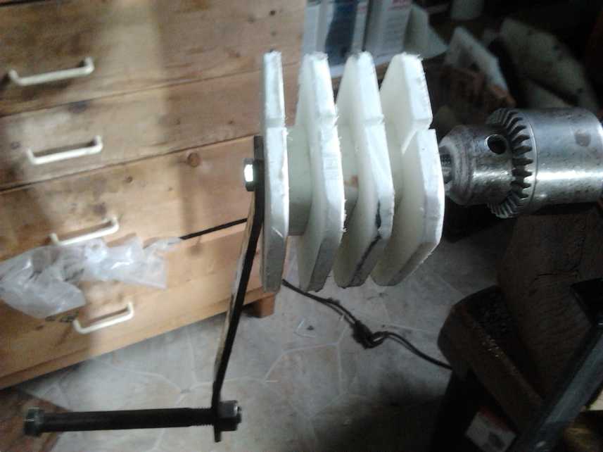 On the 18th I
made 2 more side walls for the coil winder,
to allow me to wind 3 coils all at once. That way, I could leave a 15"
loop of wire to reach between coils 1 to 2 and 2 to 3, so the sets of 3
coils per phase could be installed pre-wired in series without any
soldering.
On the 18th I
made 2 more side walls for the coil winder,
to allow me to wind 3 coils all at once. That way, I could leave a 15"
loop of wire to reach between coils 1 to 2 and 2 to 3, so the sets of 3
coils per phase could be installed pre-wired in series without any
soldering.
With these winders, I finally learned another lesson and
used polyethylene types of plastic throughout, that epoxy wouldn't
stick to.
The next day (19th), when I
was shopping there anyway, I
found some 1/2" UHMW at Industrial Plastics, and bought a piece. I
decided to make the coils 1/2" thick after all, but to use the
10mm(7/16") outside mold as above. Best to make the first coils the
prescribed 1/2" thickness - and to fit in as much copper wire as
possible for highest power with the least heat. On the 20th I cut out a
set of the 1/2" thick coil winding centers on the CNC router. I
wondered if it was really 1/2", or if it was metric, 13mm. The calipers
said it was 12.85mm, 1/2 way in between. I could wind four strands of
#15 wire instead of 3, for the equivalent of a #9 AWG wire. 80 amps is
a lot of current. If I used 48 volts, the current would be down to 40
amps, but then it would need to be 42 turns. It would need exactly the
same wires for the same power, whatever the voltage.
With a lot of trouble and kinking of wire, on the evening
of the 22nd I took my #15 wire and folded it into 4 equal lengths. Next
time I'll do it in daylight, outdoors where there's lots of room. I'm
wasn't eager to try winding 4 strands at once, and I hoped there was
enough wire to wind 3 coils from. Perhaps I should try to find a second
spool and wind doubled wires from two spools instead of 4 from one?
Probably one wire each from four spools would be proper, but I'd have
to make another spool holder - and find more wire spools.
I'm even less sure about winding 3 coils at once with
multiple strands. (One fat wire? ...do they even make #9 magnet wire?)
ROTORS
 Having put a hold on the rotors at Victoria Waterjet, I was anxious to
get a revised design to them.
Having put a hold on the rotors at Victoria Waterjet, I was anxious to
get a revised design to them.
On the 18th also, I decided to tackle the rotor "properly"
with a CAD program and send Victoria Waterjet a .DXF file. I'd been
given an old copy of "Key CAD" for Windows with a paper manual, and I
installed it. I got frustrated pretty fast with not figuring out how to
do things, and went back to LibreCad in Linux. It was as unintuitive
and obtuse as ever, but having used it however long ago, I started to
remember or figure out how to draw the things I wanted. I gained some
confidence with it and I had the rotor done before bedtime.
And I began to wonder if maybe the majority of CAD
programs are fairly similar and that I was having trouble just because
I wasn't familiar with them.
But I had quickly understood and (mostly) liked OpenSCad
from day one, and Rhino 3D seemed to work like a charm for Victoria
Waterjet.
As previously
indicated, the outer edge has straight sections to wrap the strapping
over the magnets to the slots, and the "scallops" are to reduce weight.
The "square" holes are for the other end of the magnet strapping and
for ventilation.
 The 12 holes are actually 3
sets of 4, each set of 4 at 90°, One is 50mm radius for 12mm wheel
stud bolts, one is 4" radius for 1/2" studs, and one is 100mm and 3/8"
holes - which might be for 3/8" threaded rod, or could be threaded for
1/2" threaded rod. These allow the original mounting on self contained
car wheel hubs, or trailer wheel hubs, with bearings per the original
Piggott windplant design.
The 12 holes are actually 3
sets of 4, each set of 4 at 90°, One is 50mm radius for 12mm wheel
stud bolts, one is 4" radius for 1/2" studs, and one is 100mm and 3/8"
holes - which might be for 3/8" threaded rod, or could be threaded for
1/2" threaded rod. These allow the original mounting on self contained
car wheel hubs, or trailer wheel hubs, with bearings per the original
Piggott windplant design.
Then the center hole and the 6 surrounding it
are for SDS size "taper lock shaft bushings" ("taper lock hubs"
describes them better) to mount the rotors on an axle as I plan to do.
(As the bolts are tightened, the rotor is pulled onto the slightly
tapered hub, which has a slot(s) and squeezes tight against the shaft.)
The CAD file must have been a good idea. Just 2 days later
(20th) I got an invoice e-mailed from Victoria Waterjet, which meant
they were done. They were over 70$/rotor for the four - even tho cut
from my own steel. I didn't have an estimate in mind, but I hadn't
expected over 50$.
I picked them up the next day. A worker explained that the
machine had to stop, lift up, traverse and drop down again for each new
start. So the fact of many separate holes, more than the length of cut
for each one, increased the machine time quite a lot. Maybe I'll drop
some of those alternate optional holes! 7 bolt holes out of 18, or
perhaps even 11, could be eliminated with little loss of mounting
possibilities. And I really have no plans for using the Piggott type of
mounting system myself.
I also picked up my paper drawings and found that I hadn't
made the same error in hole placements on the rotor that I had on the
stator. But obviously it was best to do my drawings as CAD files anyway.
 I thought one
other rotor mounting possibility, requiring no bolt holes, would be the
"weld-on hub" type of center. Of course the diameter was different than
the SDS hub. The mid-size hub was close. A weld could cross the gap,
but how might one be sure the rotor was centered? It occurred to me
that one could turn a narrow "shoulder" on the hub on a lathe of the
rotor's inside diameter, to hold it flat and centered while it was
being welded. The rotor would fit a little closer to the center of the
hub (and to its set screws) rather than very close to one end.
Doubtless a larger weld-on hub could have its shoulder turned down to
fit the rotor, but the small 'extra' shoulder on the medium would take
only a little milling.
I thought one
other rotor mounting possibility, requiring no bolt holes, would be the
"weld-on hub" type of center. Of course the diameter was different than
the SDS hub. The mid-size hub was close. A weld could cross the gap,
but how might one be sure the rotor was centered? It occurred to me
that one could turn a narrow "shoulder" on the hub on a lathe of the
rotor's inside diameter, to hold it flat and centered while it was
being welded. The rotor would fit a little closer to the center of the
hub (and to its set screws) rather than very close to one end.
Doubtless a larger weld-on hub could have its shoulder turned down to
fit the rotor, but the small 'extra' shoulder on the medium would take
only a little milling.
One might lighten things up with "H" size taper lock hubs,
and the small size weld-on hub was almost the same diameter. My
objection to "H" bushings is that with only two bolts instead of three,
one can't fully adjust the angle of the plate for straight turning. The
pulleys they usually mount are thick and will be straight, but the
thinner rotors - admittedly not what the taper lock hubs were designed
for - can be crooked if the bolts aren't done up evenly. And the
problem will be noticeable with these large diameters.
With either type of hub, the rotors attach to
the shaft.
The shaft attaches via bearings to the end plates or 'bells'.
The stator, with its large center hole, misses the shaft and
all its attachments. It attaches to the outside of the case.
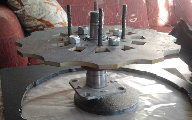
The above are
end rotors. A future plan is inner rotors for multi-stator machines.
These would go between stators where there are two or more. They are to
be cast from epoxy and made thin so that one face of each magnet faces
each stator. Thus each additional stator requires only one additional
rotor, and adds only 1-1/4" to the length of the internal components. I
found a smaller center rotor (and weld-on hub) that looked like it
might make a good solid center plate for such a rotor. Rods and nuts in
the bolts holes, which match those on my rotors, can be used to
fine-adjust the position and gap for the center rotor.
http://www.TurquoiseEnergy.com
Victoria BC Canada