Turquoise
Energy Ltd. News #111
covering April, May, June, July and August 2017 (posted
September 15th 2017)
Haida Gwaii, BC
by Craig Carmichael
www.TurquoiseEnergy.com
= www.ElectricCaik.com
= www.ElectricHubcap.com
= www.ElectricWeel.com
Month In Brief
(Project Summaries & short project reports)
- House Move - Project Selections - Electric(?) Ground Effect Vehicle -
Lambda Ray Converter - Upgraded Electric Caik Outboard Test ...&
the next "Hubcap" type motor improvement - A Nickel-Air Battery Note -
LED Lighting - Suzuki Swift: Burned an EV (Yow!) - Miles Electric Truck
Chain Drive
In Passing
(Miscellaneous topics, editorial comments & opinionated rants)
- Haida Gwaii (AKA Queen Charlotte Islands) - The Move - A Trip Back to
Victoria - Antigravity in a Dream? - Time of day - Sigh, Chem Trails
Again! - Possible Health Ideas: Cyst and maybe Mole Removal or
Shrinking? - Easier Shelling of Peas and Beans?
- In Tedious
Depth
Project Reports -
Electric
Transport - Electric Hubcap Motor Systems
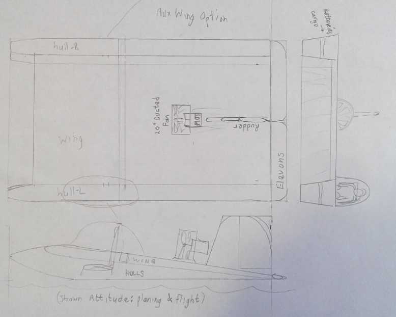
* Electric Bixel Ground Effect Vehicle: - Ducted Fan etc. - The "paper
airplane" delta wing design - back to Catamaran design
Other "Green"
Electric Equipment Projects (no reports)
Electricity Generation
* New Water Flow Turbine Design Thoughts
* Ocean Wave Power Thoughts
* Short Space Ray/Lambda Ray/VHE Ray Converter: - Circuit Board is
working - Programming - How it Works: A bit of speculation
Electricity Storage - Turquoise Battery
Project (NiMn, NiNi, O2-Ni), etc. (no reports)
April... May... June... July... and August in Brief
I was very busy all spring and summer with the move to Haida Gwaii and
setting up home and shop there, and there is still a lot to do. I wrote
a lot about that, then decided it was mostly of interest to friends and
relatives, and here I include just a bare outline, in the "In Passing"
section. I found it was harder to get
internet up here than I had expected, and without internet at home I
couldn't post newsletters. It has been a challenge getting all my
stuff moved, and I was without the computer I usually write the
newsletters and edit the pictures on. I was missing parts and tools for
working on almost any green energy project. I typed article text on a
combo-tablet that had a keyboard. Meanwhile the months rolled on. I
wrote haphazardly on two different machines, and it became a
hodge-podge that took considerable editing to merge into organized
texts. And there were dozens of pictures, taken over 4 months.
Luckily there is cell phone service in my area. (Some
areas don't even have that.) Late in May I got a new cell phone, one
that I could use
as a "WIFI hot spot" and get on the internet. (The price for using that
very much is steep, but at least I could get on line from home
occasionally.) Late in July I got my trailer which had been stored in
Cache Creek and which had much of my computer equipment in it including
the one I do the newsletters on, with the subscription list. Now I
could upload and edit all those pictures I'd taken - but with so much
to do I didn't get around to it. In mid August I
bought a "WIFI Range Extender" which also had an ethernet connector so
I could connect that old desk computer via WIFI. (Similar WIFI items I
had ordered from
China in June or July finally arrived on September 11th.) So I finally
wrapped up
this TE News, #111, which had become more than plenty long with a lot
of loose ends. But it didn't work. While the physical connections are
there, these WIFI devices expect the LAN to be on the ethernet and the
computer(s) to be on the WIFI instead of the other way around.
I saved a lengthy and revealing In Passing article
about World War Two, based on the works of Victor Suvarov, for next
issue. (and you thought you pretty much knew what that war was about?
So did I. Hah!)
In these months I couldn't do much with green energy
projects except study and plan. I first considered the tidal power
project at Delkatla estuary, and the Differential Variable
Transmission, and a couple of other projects. But there seemed to be no
local interest in actually doing the Delkatla project - at least none I
managed to get in touch with. Finally I decided to concentrate on two
projects that seemed to me to be more valuable than any of the others.
Electric(?) Ground Effect Vehicle
Ground effect vehicles seem to me to be the best way to
open up transportation to islands, between islands, and along
inaccessible coastlines, especially mountainous ones cut by fjords and
inlets where road building is circuitous or impractical. Today's
options are usually airlines (costly) and ferries (slow). The subject
has become of great interest to me since I now live on an island rather
remote from the main stream of human activities, which would become
much more accessible with such a craft.
The ground effect vessel flies over the water at very low
altitude with the speed of an aircraft, with less special 'pilot'
training and 1/3 the energy cost, a "sea bus" enabling many local or
intermediate distance routes to be traveled quickly and economically.
In scale it could be anything from a personal "sea car" to a ferry
carrying vehicles.
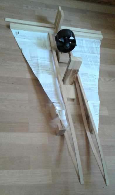
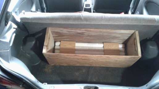
Mock-up of the delta wing shape - imagine the
center as a solid hull instead of just an outline.
But the catamaran shape seems more practical.
 My idea of the best form for the ground effect vehicle
metamorphosed from a catamaran with optional stubby outer wings to a
"paper airplane" delta shape... and, on reviewing some videos, back
again.
The paper airplane flew well and the delta wing shape seemed "cool",
but it seems two outer hulls with a
main wing between them traps air at the sides as well as the back, so
the air scooped in the front under the wing has nowhere to go except to
lift the vehicle out of the water. So this rather "boxy" looking shape
is almost inevitably going to give the best performance, stability
and fuel economy. And it would be easier to dock and to embark
and disembark. But one radio control modeler said when he added stubby
wings to the outside of the floats, it worked better. And that's the
configuration Bixel seemed to use and showed in his patent drawings. I
tend to think simply making the catamaran wider, even square viewed
from above, could accomplish the same thing.
My idea of the best form for the ground effect vehicle
metamorphosed from a catamaran with optional stubby outer wings to a
"paper airplane" delta shape... and, on reviewing some videos, back
again.
The paper airplane flew well and the delta wing shape seemed "cool",
but it seems two outer hulls with a
main wing between them traps air at the sides as well as the back, so
the air scooped in the front under the wing has nowhere to go except to
lift the vehicle out of the water. So this rather "boxy" looking shape
is almost inevitably going to give the best performance, stability
and fuel economy. And it would be easier to dock and to embark
and disembark. But one radio control modeler said when he added stubby
wings to the outside of the floats, it worked better. And that's the
configuration Bixel seemed to use and showed in his patent drawings. I
tend to think simply making the catamaran wider, even square viewed
from above, could accomplish the same thing.
Unexpectedly I have a
complete electric drive system that will run at 10 or 15 kilowatts,
with 30 KW briefly for take-off, and (while realizing it won't cover
long cross-ocean routes) I now hope to make the prototype manned craft
electric instead of gasoline. But before that will come the electric
radio controlled ("RC")
1/4 scale model.
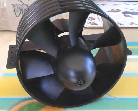 In order to maximize thrust for take-off using
the least amount of power, I'll be using a
ducted fan propeller, as they have more static thrust per
horsepower. And perhaps the unit can be mounted at the front with the
air aimed or further ducted to blow under the wing instead of over it.
That should increase lift for take-off at a lower speed. For the model
I found a 5" plastic ducted fan at "Hobby
King". I don't know where I'll get a 20" or larger one for the full
size
craft. The "turbofan", the common jet aircraft engine, is a ducted fan
propeller turned by a turbine.
In order to maximize thrust for take-off using
the least amount of power, I'll be using a
ducted fan propeller, as they have more static thrust per
horsepower. And perhaps the unit can be mounted at the front with the
air aimed or further ducted to blow under the wing instead of over it.
That should increase lift for take-off at a lower speed. For the model
I found a 5" plastic ducted fan at "Hobby
King". I don't know where I'll get a 20" or larger one for the full
size
craft. The "turbofan", the common jet aircraft engine, is a ducted fan
propeller turned by a turbine.
I didn't get the radio control parts from storage until
the start of September, and without knowing how it would all fit
together I held off building more than a "mock-up", and that was of the
delta wing design.
 In the catamaran design, air scooped in under
the front of the wing has nowhere to
In the catamaran design, air scooped in under
the front of the wing has nowhere to
escape out the back and sides except by lifting the craft out of the
water.
At the start of September I conceived of the ducted fan
being at the front and blowing air under the wing instead of over it
for still more lift and lower take-off speed. Others have done that
with models, but it looks more practical with a small diameter ducted
fan than with a big propeller.
VHE/Lambda Ray Converter
The other especially useful project was one item that did
arrive in the shipping container in April before
I did. It was a cardboard box labeled "Lambda", which had the parts and
pieces related to the project. It seemed to be one project I should be
able to work on - at least, once I got my computers back. If I could
get it to work, it might replace any and all other means for generating
electricity that I might work on. And it could even make battery
storage and hence better batteries much less important. It would be
relatively easy to duplicate units and I could do it without help and
interest from others, which seemed to be lacking.
So the on again off again
converter project was on again as of late July when I got my computers
back, with the control board schematics and the software development
system for writing
MSP430 microcontroller software. This time I hope to get as far as a
fairly well built coils/antenna unit in a "bread pan" steel box, a
working microcontroller based coil pulse control board, and trying out
what might be a viable software strategy for turning the rays into
electricity via those circuits.
In August I got the circuit board that I made a year and a
half ago working (at least, the microcontroller ran - not without some
initial trouble and confusion), and I made
much progress on writing the software. Sometime earlier I realized I
had the IRF7307 predriver chip connected wrong
and I fixed the design for the present circuit board. But going back to
the earlier
experimenters' schematics, which I had copied the much of the driver
circuit from, I found they all used the same circuit and they all had
it wired wrong,
identically! My own original
mistake was in copying the original mistake! Everyone had simply copied
the
first person's cludge job assuming it had been properly designed, and
so they were all working under a considerable handicap with poor and
uncertain drive to
the power mosfets and hence to the coils. This may help explain why
they got unpredictable results and no successful converters. In August
I finally realized it was a poor choice of chips to start with - there
are lots of more suitable ones.
Recognizing these rather basic electronics flaws was
actually inspiring. Notwithstanding Mark's safety warnings and emphasis
on the difficulties, it gives me good hope that, using the flexibility
and precision control gained by using a microcontroller instead of
simple discrete circuits and oscillators, it just might be easier than
it seems - or even "pretty simple" - to convert VHE rays into
electricity.
I seem to have cludged my board to where it'll probably
work, but
owing to the poor choice predriver chips (even when connected right)
compounded by
power supply issues, I'm already wanting version 2 of the board to
improve the power mosfet drive while also getting the MSP running
within its specified voltage. I picked another mosfet gate driver chip
and ordered a few from Digikey. Meanwhile it is most helpful that the
MSP hasn't blown up yet at 5.2 volts, when
its "absolute maximum" rating is 4.1 volts.
On reading one experimenter's report I realized it would
be just as
necessary to varnish or epoxy all the coil wires solidly into place on
this unit as it is on an electric motor, or the wires would vibrate
until they shorted or broke.
I also started to dimly see an important aspect of the
operation. When the control coils pulse their high voltage pulses and
the sudden change in voltage triggers the lambda rays to release their
VHE electromagnetic energies, those energies don't simply appear in the
"collector coil". Instead, they are transformed into far lower
frequency radio (and or other wavelengths) energies in the areas around
the coils. These are in turn induced by electromagnetism into the
collector coil in the same way as into the secondary of a transformer
or perhaps more akin to lighting an unconnected light bulb near a radio
transmitter antenna. Here we may begin to appreciate why there may be
strange glows or electric arcs around the unit, how people can get RF
or radiation burns to their hands from them, and how Mark's earlier
transistorized versions didn't work because there was too much
electrical interference in the air, getting into the delicate circuits.
In some ways, I find lambda ray conversion to be a boring
project. There's no exciting spinning parts and not much machining or
fabricating to do. There's a fair bit of microcontroller programming,
but I've already done more programming than anyone should in a single
lifetime, and nowadays I can hardly stomach sitting down at a computer
to do it. Of course, a bit of success could go a long way to making it
more interesting!
While those were to be the two main projects for the time
being, other things deserved putting a little effort into on the way,
too.
Upgraded Electric Caik Outboard Test (Continued from TE News #104
& 105)
...& the next "Hubcap" type motor improvement
One thing I'd been wanting to do for a long time was to
test the Electric Caik outboard motor, repaired and with its
rotor upgraded for higher RPM.s almost a year ago. But somehow I'd
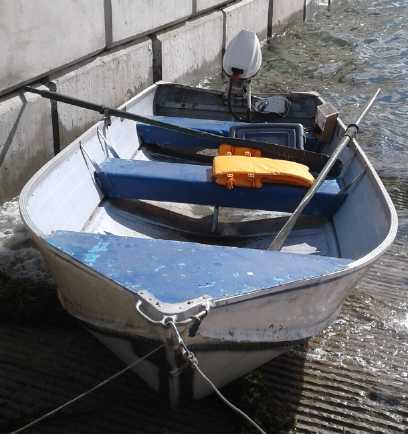
never managed to get the boat in the water. On September 6th, with my
14 foot aluminum boat and all finally at my new abode, I did some
repairs to the trailer (maybe lucky the boat made it up here without
falling off!), mounted the outboard and equipment in the boat with
eight 100 amp-hour lithium batteries (about 25 volts), and by the next
afternoon, the 7th, I turned it on. Everything worked properly on the
first try, so I hitched it up and drove down to the boat launch at
Queen Charlotte. Aside from stupid little things like leaving the drain
plug out of the boat when I launched it, and not bringing a bailing
bucket along, the trip went smoothly.
The outboard was rather noisy instead of virtually silent, which
experience says indicates downward pressure from the motor onto the
drive shaft. (Why?) But not loud like a gas outboard! There was a fair
crosswind but I seemed to have navigation - ie, I could steer anywhere
without the wind blowing me back - at only about 10 amps. Running at 25
volts instead of 16 or 18 helps. I ran it at different amperages (as
redd on the cheap Chinese shunt meter - not very steady readings and
probably just a little lower than the actual current) and got the
following results:
Amps - RPM
20 - 1530
30 - 1800
40 - 2000
50 - 2100
60 - 2250
At 50 amps the breaker blew after a bit. (25v*50A=1250
watts.) Well, it's a 50 amp breaker, and maybe it was really 55(?) amps
or so. Of course, it took me by surprise "Groan! Something's fried!",
but only for a moment before I realized what it was. Reading 60 amps it
blew pretty soon. With the improved rotor I wasn't worried about rotor
magnets potentially flying off when going to higher RPM.s, but about 60
amps and 2250 RPM was 'full throttle'. I was a bit surprised by this as
I thought it would go higher. But the limits are set by the shunt wire
in the controller. If I changed that, it could do more... if it didn't
blow the controller or overheat the motor.
Later, I found the control, which I contrived to mount
inside the arm of the outboard when I first did it in order to use the
original twist grip 'throttle', was acting up. It may not have been
reaching the end of the travel of the potentiometer and hence full
speed. But now I'm not sure the twist grip in the arm is actually the
best place for a speed control. It's arguably best for starting a gas
motor and for maneuvering, but in steady travel you're always turning
it by accident and it's hard to keep a steady speed unless it's at
maximum, and even there you're trying to twist it extra so as not to
inadvertently slow down. A control one can set and leave would probably
be better, especially when it'll often be run at part speed to conserve
battery power, and I think I'll convert it to that setup.
The boat didn't get up on a plane, but as there wasn't too
much weight in it, it probably wasn't too much short of a soft sort of
plane. From driving lessons when I was 18: 60 MPH is 88 feet per second
- close enough to 90. So 6 MPH is 9 FPS. So 15 FPS, my best very rough
estimate at 60 amps and 2250 motor RPM, is about 10 MPH. So assuming
proportional RPM to speed: 2100 RPM is 9.3 MPH, 2000 = 8.8, 1800 = 8,
and 1530 = 6.8. Note that the speed at 1/3 power (20 amps) was 2/3 of
the speed at 60 amps. One sees how with a displacement hull, power
consumption increases dramatically to gain just a bit more boat speed.
 I guess I must
have run it longer and harder than on previous occasions. I forgot to
connect a meter to read the temperature, but afterward the motor was
certainly hot. I wouldn't want it much if any hotter. I was rather
disappointed after it had seemed to stay so cool on previous tests with
similar currents. I guess the "continuous duty" rating would be
somewhere around 1200 watts or 2 horsepower, and nowhere near my
evidently overrated thoughts of 3000 or more. But I'm not surprised,
having in the meantime seen how fast the Electric Hubcap motor
coils could get hot in the Sprint car when supplied with up to 150 amps
(*36 V = 5400 W) from the Kelly BLDC motor controller. The heads of the
(metal) coil clamping bolts (electromagnetically heated by the spinning
rotor magnets, with no electrical or good thermal connection to
anything else) were especially hot, to no benefit. I thought I had
replaced those with nylon bolts... but I guess that was in the next,
unipolar, version of the Caik motor. There might be some gain from
replacing them, and also by taking the hood off the outboard to get
better air circulation to the motor - the hood must certainly trap the
hot air.
I guess I must
have run it longer and harder than on previous occasions. I forgot to
connect a meter to read the temperature, but afterward the motor was
certainly hot. I wouldn't want it much if any hotter. I was rather
disappointed after it had seemed to stay so cool on previous tests with
similar currents. I guess the "continuous duty" rating would be
somewhere around 1200 watts or 2 horsepower, and nowhere near my
evidently overrated thoughts of 3000 or more. But I'm not surprised,
having in the meantime seen how fast the Electric Hubcap motor
coils could get hot in the Sprint car when supplied with up to 150 amps
(*36 V = 5400 W) from the Kelly BLDC motor controller. The heads of the
(metal) coil clamping bolts (electromagnetically heated by the spinning
rotor magnets, with no electrical or good thermal connection to
anything else) were especially hot, to no benefit. I thought I had
replaced those with nylon bolts... but I guess that was in the next,
unipolar, version of the Caik motor. There might be some gain from
replacing them, and also by taking the hood off the outboard to get
better air circulation to the motor - the hood must certainly trap the
hot air.
Improving the motors
In most motors, the copper wires are close enough to the
iron that some heat is carried off through the iron, and heat radiates
off everywhere. With my largely plastic motors, only air cools the coil
wires. Now I'm thinking of modifying the mold design for all my
"hubcap" type motors to get air flow over more surfaces of the coil
wires - exposing the bottom (and if possible the top) of the donut as
well as the outside edge. The problem with exposing the top is that the
flux gap has to be larger, and it may become too large. I've been
making my motors occasionally since 2008 and probably achieved
excellent efficiency about 2012 (IIRC), and it's amazing that I keep on
discovering very significant ways in which they can be improved.
And perhaps an appropriately ducted "computer fan" that
comes on whenever the motor is on, could be used to improve air flow.
The magnets acting as centrifugal fan blades seem to move air nicely,
but perhaps it needs to be flowing faster. A lot of electric car motors
that pack much power into a small size are liquid cooled. Partly
because of presumably high efficiency making less heat I don't think
I need to go to that extreme, but it's evident they would handle more
power with better cooling.
I may add a couple more battery cells for about 31-32
volts and try the boat again some time with this boost. OTOH, at least
at 24 volts I haven't yet blown my motor controller or burned out the
motor.
I didn't think to take any pictures or video until I was
back at the launch ramp.
A Nickel-Air Battery Note
The desire for lighter weight batteries for an electric
version of the low flying "sea craft" brought my thoughts back to the
potential for nickel-air batteries to fulfill that sort of role. A
metal negative electrode is light and compact compared with the
oxide/hydroxide based positive. Hence, using air to replace the heavy
electrode is an attractive idea that could potentially drop 3/4 of the
weight of a cell. Attempts to produce rechargable zinc-air cells do not
so far seem to have resulted in practical products. Seemingly few have
tried any other metal.
I've probably mentioned this before, but I'll bring it up
again: why would nickel-air be better than zinc-zir or most other
metals that might be tried with air?
1. The reaction voltage of nickel to nickel hydroxide (-.72 V in
alkali) is less than that of water to hydrogen (about -.83 V in
alkali). The nickel won't spontaneously oxidize in solution in the
presence of oxygen as do cadmium, iron, metal hydride and zinc. (hence
its well known corrosion resistance). Oxygen reaching the metal
electrode is hard to avoid in a cell that can't be sealed and where
oxygen is deliberately admitted for the air electrode.
2. Theoretical amp-hours aside, nickel has been determined by other
researchers to have the highest effective amp-hours per weight in
aqueous solution of most anything.
What special problems are there with making a nickel-air battery?
1. As everyone knows, metallic nickel, alone of all metals, will simply
not oxidize in pH 14 alkaline solution. Non-corroding nickel or nickel
plated current collectors for the positive electrode made making
alkaline batteries simple compared to salt battery chemistries. But it
precluded using metallic nickel as an active electrode element. For
that, a salt electrolyte must be used instead. The reactions are
nevertheless alkaline, but at a reduced pH, usually settling in at 12
to 13.
2. A chloride salt can't be used. KCl worked great with Ni-Mn with the
manganese negative electrode. But for reasons I don't understand (and I
have no formal training in chemistry) any cell I made with a metallic
nickel electrode underwent continuous self-discharge in chloride
solution and wouldn't hold a charge at all. Potassium sulfate seemed to
work much better. Oxalic acid also seemed to work. To use an acid
electrolyte one must choose an acid which won't dissolve the metal or
its reaction products. Neither nickel, nickel oxide, nor nickel oxalate
dissolves in oxalic acid. This is about the only common acid which will
work. Most acids will dissolve most lighter molecular weight metals and
so can only work with heavy ones like lead.
New House - LED Lighting
I brought what I thought was a lot of LED "light bulbs" to
my new abode, and three 4-foot, plug-in "fluorescent" style LED
fixtures. I immediately replaced the incandescent and compact
fluorescent "bulbs" in the house, buying more from the local building
supply (at a substantially higher but not outrageous price) when I ran
out.
I took the four fluorescent lights out of the workshop. In
two I put in receptacles and hung up two of the plug-in LED "fixtures".
For the other two I installed simple screw-in sockets and used the
"light bulbs". In one of these I put a "Y" and used two "bulbs" to
light the darkest corner. Now instead of 272 watts of "Super Saver" 34
watt fluorescent tubes, it has under 100 watts of LED lights and is
much brighter and more pleasant. The growling transformer hum
is gone and the room is quiet. One thing I would note is that some of
the 4' LED fixtures flicker at 60 or 120 Hz. That seems needless in
this day and age and with LED technology - cheapskates! How can you
find that out before you buy them instead of after? Some seem to
flicker somewhat but only dim-to-bright rather than on-off like old
fluorescents.
I also managed to change the fluorescent tube fixture in
the laundry room, but those in the kitchen and dining area are recessed
into the ceiling and are going to be a greater challenge. When
installed they were doubtless considered "deluxe", stylish, and "energy
saving". Now the elaborate settings just made it hard to change them
out for something better.
As an added benefit to LED lights, "LED" is much shorter
to type than "incandescent" or "fluorescent". Those long words will
mostly fade out of common use with their lighting types.
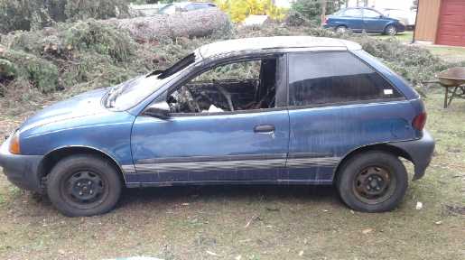
Suzuki Swift: Burned an EV (Yow!)
 Embarrassing
to admit. With the Swift not having
quite enough range to get to town and back with a good safety margin, I
tried a battery experiment of adding 80 NiMH batteries, in series, to
the lithium ones. I thought that if I just made sure there were enough
NiMH cells that they couldn't be overcharged by the regular chargers in
the car, I could do it safely. But it seemed that however many cells I
put in the string (I was up to 83), the charger would up the anti and
put out a higher voltage. I didn't get much chance to figure out what
was going on before a day when I wasn't feeling well (a tooth) and I
had a long nap. Even before the nap the meter reading, another all-time
high voltage, should have triggered an alarm bell in my head. And
regardless I
should have come back soon to check.
Embarrassing
to admit. With the Swift not having
quite enough range to get to town and back with a good safety margin, I
tried a battery experiment of adding 80 NiMH batteries, in series, to
the lithium ones. I thought that if I just made sure there were enough
NiMH cells that they couldn't be overcharged by the regular chargers in
the car, I could do it safely. But it seemed that however many cells I
put in the string (I was up to 83), the charger would up the anti and
put out a higher voltage. I didn't get much chance to figure out what
was going on before a day when I wasn't feeling well (a tooth) and I
had a long nap. Even before the nap the meter reading, another all-time
high voltage, should have triggered an alarm bell in my head. And
regardless I
should have come back soon to check.
 Instead, the
batteries were being
badly overcharged and the next thought of the car was 3 hours later
when the horn
started blaring. The car had caught fire and the interior was a blazing
mess. I put it out with the nearby garden hose through the open garage
door and through the broken windshield, and shortly Tom brought the
fire extinguisher, which sped the process up. The garage door above the
car was charred. Thank God, the horn going off saved the house! The
firewall stopped the fire so all the electric drive components under
the hood, as well as the lithium batteries in their metal box under the
back seat, were still fine, along with all the heavy cables which were
run along the floor. I had all the components to do another electric
car conversion except the meters that were mounted above the dash,
which had melted.
Instead, the
batteries were being
badly overcharged and the next thought of the car was 3 hours later
when the horn
started blaring. The car had caught fire and the interior was a blazing
mess. I put it out with the nearby garden hose through the open garage
door and through the broken windshield, and shortly Tom brought the
fire extinguisher, which sped the process up. The garage door above the
car was charred. Thank God, the horn going off saved the house! The
firewall stopped the fire so all the electric drive components under
the hood, as well as the lithium batteries in their metal box under the
back seat, were still fine, along with all the heavy cables which were
run along the floor. I had all the components to do another electric
car conversion except the meters that were mounted above the dash,
which had melted.
The loss of the Swift has already cost hundreds of dollars
in extra gasoline. Someone was interested in bringing Nissan Leaf
electric cars up to Haida Gwaii, which sounded great. Now he hasn't
answered his phone in recent weeks. But now another person, one who
lives here, is (evidently) a great mechanic, and is wealthy, wants to
bring some up and to build a garage and convert cars and boats
to electric here! Even better! If it pans out, the electric drive from
the Swift is going to be used for the ground effect vehicle for
"driving" over the water. And if it pans out, perhaps we'll be making
motors, controllers and differential variable transmissions.
 One can
overcharge lithium batteries too. I hooked some of the ones I got from
an old Toyota Prius (which I initially thought were NiMH) to a solar
panel. If all 5 cells were good, they charged up okay. But if one or
two were shorted, the others charged to much too high a voltage. I
guess that makes gas, which swelled the cells up.
One can
overcharge lithium batteries too. I hooked some of the ones I got from
an old Toyota Prius (which I initially thought were NiMH) to a solar
panel. If all 5 cells were good, they charged up okay. But if one or
two were shorted, the others charged to much too high a voltage. I
guess that makes gas, which swelled the cells up.
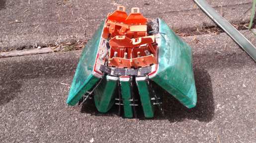
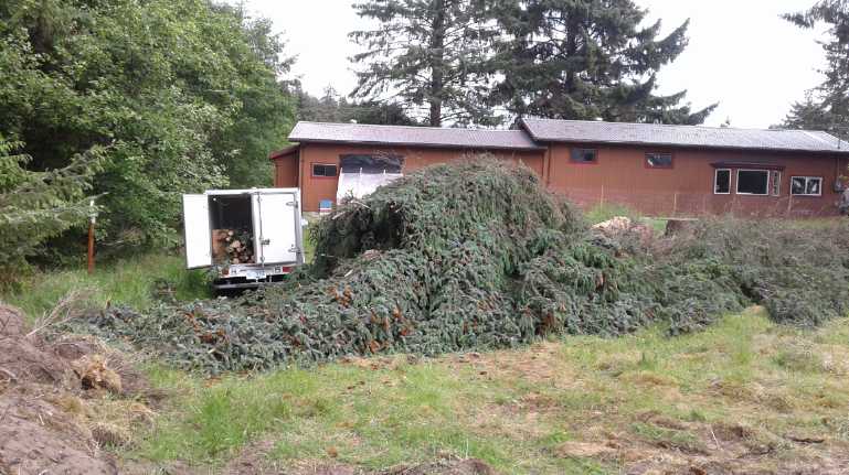
Miles Electric Truck Chain Drive
Using the Miles electric
truck... to haul branches from a cut-down tree
 The low speed
Miles electric truck has been
pretty useless
around here so far, with the driveway going straight onto a high-speed
highway. I didn't bother to renew the insurance for the
road. Quite some issues back I mentioned ways I had devised to attach a
motor to a vehicle wheel with a chain or toothed belt drive. I now
thought about doing so with the Miles. The idea would be that the extra
efficiency gained by going so directly from the motor to the wheel,
bypassing the lossy transmission and drive train parts (which I would
simply remove), I could use a lower reduction ratio, speeding up the
truck and increasing its range by perhaps 50%, with the same motor
speeds and powers.
The low speed
Miles electric truck has been
pretty useless
around here so far, with the driveway going straight onto a high-speed
highway. I didn't bother to renew the insurance for the
road. Quite some issues back I mentioned ways I had devised to attach a
motor to a vehicle wheel with a chain or toothed belt drive. I now
thought about doing so with the Miles. The idea would be that the extra
efficiency gained by going so directly from the motor to the wheel,
bypassing the lossy transmission and drive train parts (which I would
simply remove), I could use a lower reduction ratio, speeding up the
truck and increasing its range by perhaps 50%, with the same motor
speeds and powers.
I'm ordering a 120 tooth and 12 tooth sprocket set for a
10
times speed reduction, from Rebel Gears. 120 teeth, with #40 chain, was
the biggest that would fit on the back wheel. This is probably a change
from about 15 times reduction in the original drive train. (I'll try to
take the end off the motor so I can see it, and determine the actual
ratio before disassembly.) That should take it from about 40 max to 60
max KmPH and
similarly increase the range. It would still be more useful in town
than on the highway, but it should prove the point.
If the mechanical end of the project looked tough but
doable, the wiring for the motor moved to a new position in front of
the rear right wheel seemed like just as big a problem. I doubt it
would be wise to lengthen the three heavy wires from the motor
controller to the motor, so the controller will have to be moved from
between the two seats into the back of the truck. It has a plug with 34
pins with wires coming to it from various sources, and no extra length
of wire for any. I expect the only practical solution will be to cut
the whole cable and splice in another 6 feet of wire so it can reach,
for every wire in the cable.
Anyway, I'll order the sprockets, and then tackle this
project
some time when I have some time - or perhaps
hire someone to do some of it.
In Passing
(Miscellaneous topics, editorial comments & opinionated rants)
Haida Gwaii (AKA Queen Charlotte Islands) - BC, Canada
The whole archipelago of Haida Gwaii, situated on the
outer edge of the continental shelf of western North America, is about
the size of the island of Hawaii, which is home to some 100,000 people.
Haida Gwaii has under 5000 except in summer, when there is an influx of
tourists. Trout, and sea food from shellfish and crabs to halibut and
salmon, abound. There are no wolves, cougars or grizzly bears, and the
large black bears aren't usually aggressive. Small Sika deer, imported
a century ago, abound. With no natural enemies they are considered
pests and no one minds people putting one or even a few in their
freezer. I planted a garden, and it seems unlikely anyone will go
hungry here if the regular delivery chain is interrupted. But the
weather this spring (apparently unusually cold and windy) meant that
many things would only grow well in a greenhouse, and this may still be
true most years.
One can see that if the average temperature was just a few
degrees warmer, people would flock here to live. Cold winters are one
thing, but summers where one might wear a sweater much of the time are
considered desirable by few. Enter global warming. According to locals,
last summer this was Canada's warmest spot more than once. However
interesting and unusual, this occurrence was never mentioned in the
news. But this summer has been exceptionally cold and wet. At least we
have had no forest fires, hurricanes, floods or notable earthquakes.
Most of the people live on the largest land mass, Graham
island. The next largest, Moresby island, has just a village, Sandspit,
around an airport not far from the ferry to Graham island. The airport
is there, on the "wrong" island, because the large sand spit was a
simple place to build an airport.
The Move
The move to the house I bought on Graham Island didn't go
smoothly. Ignoring everything, I grossly overloaded the 20 foot "sea
can" shipping container and the truck couldn't budge it. Bill and I had
to hurriedly take out 1/2 the entire volume and 40% of the weight and
put it in the garage, which I had cleared of hardwood lumber only the
day before. We hurriedly shifted the rest of the weight to balance the
container, and the truck got the container off just in time to make the
April barge to Masset on Graham island. I then had to get two "U-Pak"
storage containers and store the remaining 8000 pounds of stuff. Of
course, there was no particular order to what was taken and what was
left behind. Bill refused to tow my 14' aluminum boat behind my Toyota
Echo, so I had to leave it stored at a friend's. I told him he could
sell it if he wanted.
Someone with a flat deck truck was supposed to pick up my
electric Miles truck, converted Suzuki Swift EV, and the Sprint project
car and take them to Vancouver to put on the barge. (I had them all
filled to the roof with stuff, too.) He procrastinated until they
missed the April barge, and indeed almost until I had to be gone, but
in the last couple of days he got them all, and they came up on the May
barge. It was just as well I didn't have to deal with them immediately.
On May 1st, days late, Bill and I headed out, he in the
Echo and I in the Dodge Caravan minivan towing a big utility trailer, a
converted tent trailer, with most of my remaining furniture including
my bed and sofa. Most of my clothes and personal stuff was in the
Caravan. There was a problem with the fuel pump assemblies on these
years of Caravans, and I ran out of gas 2 miles short of the first gas
station on the highway on the mainland, with the gauge still saying 1/8
of a tank remained. To make a long story short, this caused gunk in the
pump line to come loose and then the pump sucked air if the tank wasn't
5/8 full or better. This problem wasn't soon understood, and the
resulting confusion it caused led to storing the trailer at a storage
facility in Cache Creek, and later abandoning the van 40 Km south of
Quesnel and continuing with two of us in the Echo to make our ferry
reservation to Haida Gwaii on the 4th. This meant I ended up buying
clothes and furniture to make do (at unexpectedly high cost for the
furniture - double the 1400$ advertised price after shipping et al),
and huge expenses retrieving the two vehicles later on separate trips.
In the meantime, I sorely missed the items they contained. And all
summer I missed the many tools and items that were left behind in the
U-Pak containers.
There was certainly no lack of things to do around the new
house. One of my priorities was to have four huge trees near the house
cut down, and I spend weeks cutting up the branches, burning the bits
and stacking the substantial ones for firewood, which I'll need this
winter. It was like moving from the deep dark woods into an open field.
And many other things needed doing: planting the fruit trees,
unpacking, outfitting the workshop better, getting decent water from
the well or from the rain, fixing the dishwasher...
There are stores, but not many or large, and being out in
the country it's a 25 Km trip to Queen Charlotte, or 80 to Masset where
a somewhat different selection of good may be had. It should be a great
place for an electric car with sufficient range to go to either
destination, or even just to QC. But so far there's just one Nissan
Leaf (and my Miles truck) on the whole island, as far as I know.
Here are some pictures of the house and yard.
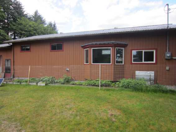 The south face of the house.
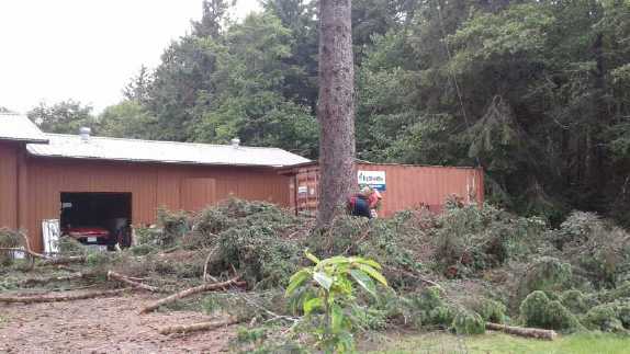 One of the trees being cut down, branch by
branch
One of the trees being cut down, branch by
branch
owing to limited space to fell it, on the north side.
 Around the front, with the highway, my strip of
trees
Around the front, with the highway, my strip of
trees
along the waterfront, beach and ocean behind me.
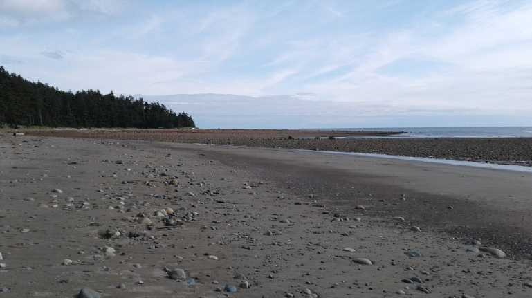
 The beach below my waterfront, looking south.
The rocks and sand seem to be rearranged daily with waves and tide -
sometimes gravel, then sand, then rocks, at any given point.
 looking north. Off to the right, about one day
a month it is clear
looking north. Off to the right, about one day
a month it is clear
enough to see some mountaintops of the BC coast on the horizon.
 Looking up from the water's edge at low tide.
The highway and the house are hidden by the trees.
 The big livingroom from just inside the bay
windows,
The big livingroom from just inside the bay
windows,
(before most of the furniture arrived).
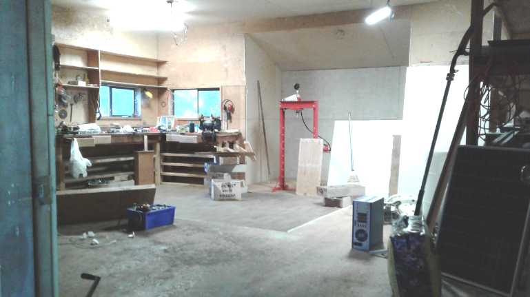 The 24' x 24' Workshop
I have much reorganizing to do.
A Trip Back to Victoria
A couple of plans to get the tons of equipment and parts
I'd left behind in two 7'x9'x7' U-Pak wooden storage containers in
Victoria delivered, didn't seem to pan out. Finally I took an airplane
to Vancouver and the ferry to Victoria (August 27th), rented a 20'
U-Haul truck, transferred everything from the U-Paks into it with the
help of a friend, attached my boat trailer behind, and brought
everything up, arriving September 2nd. I drove the length of Vancouver
island from Victoria to Port Hardy (500 Km), took the ferry from there
to Prince Rupert (16 hours), and then the one from Prince Rupert to
Skidegate on Haida Gwaii (6 hours). No more long hauls (1700 Km)
through the BC interior for me - the previous one ended up costing me
perhaps 6000$ when I ran into trouble with the minivan and then had to
retrieve it and the utility trailer with much of my furniture
separately from different areas. (Counting the extra furniture I
consequently ordered in June and the pickup truck I bought to tow the
trailer, more like 12000$.) This trip cost me about 5000$ - a bargain!
But it cost as much to take the boat on the ferries as I originally
paid to buy the boat in 1986. After I unloaded the U-Haul truck, I sent
it back "hossled" by BC Ferries to Prince Rupert (meaning driven on and
off the ferry by BC Ferries personnel so I didn't have to go myself)
and let U-Haul retrieve it from there.
Antigravity in a Dream?
Probably most or many people have seen a demo of a
gyroscope spinning at an angle on top of a rod or post, seemingly
defying gravity by not falling off the post, instead precessing around
and around it as it spins. Of course, one surmises that the downward
force on the post is equal to the weight of the gyroscope regardless of
its motions or lack thereof.
And perhaps many have once held a spinning object and
discovered that it strongly resists being turned in a desired direction
and instead tries to turn at right angles to the force applied.
If the precession of the gyroscope is forced to slow, I
presume it will start to drop until the axis is horizontal and it falls
off. Alternatively, if it were forced to speed up, would it not rise up
and spin more upright?
Some of the same properties may be seen in a pendulum,
which also has an uncentered pull on its axis of 'rotation'. (What
happens when a pendulum is forced to swing, or to rotate, faster or
slower than gravity would normally have it do? What happens if it's
pushed at right angles to its usual motion?)
Is there some unsuspected use for such properties to
counteract the downward pull of gravity? I have heard rumors of such a
thing, but I have been unable to form any concept of how it might
actually work.
Early on the morning of May 18th I had a dream. I was in
some sort of electronics products development place. Some stuff
happened that seems little relevant. Then my attention was drawn to a
rectangular-ish object perhaps 18" tall and a foot square, which slowly
levitated off the floor a couple of feet, moved over a couple of feet,
and came down again, all in a smooth arc.
I said, "You've solved the secret of antigravity! Wow,
that's a first! Or at least, the first time I've ever actually seen
such a thing." (other than rumors, I meant.)
I said, "You call it the Pendulum, but surely it has lots
of flywheels and gyroscopes in it?" (The idea of what it "must have
had" may have been merely my own preconceived notions of what such a
device "must have".) There was no verbal response and there was what
may have been a nod - or was it just a slight smile, perhaps
condescending? (Often the words of a dream bear little relation to the
scene and are the important part. In this case they seemed be
co-ordinate. But how did I know it was called "The Pendulum"? That term
was out of the blue. One suspects that if the dream may be taken at
face value, a pendulum or pendulums is or are a key component if not
the the key component.)
A small block of painted wood(?), like a child's
plaything, was levitated and set square on top of another similar one,
with a peg and a hole aligning them. [What was he meaning of this?...
It's child's play?!?] Then the original machine rose up and then moved
sideways horizontally owing to the antigravity vector being applied a
little off from the vertical axis, going across just above and then
settling on a counter top. There I awoke.
The dream seemed to come out of the blue. I had had few
prior thoughts about antigravity other than being sure it exists. My
only somewhat recent thought was that if it were discovered and
antigravity devices created in the near future, that would make the
ground effect craft obsolete, and therefore not worth developing.
(...not to mention all aircraft and hovercraft - maybe even commercial
ships)
In listening to the monthly ALTA web bot "predictive
linguistics" report summaries on youtube, Clif High's predictions of a
new field of "electro-gravitics" in the coming decades had set that
thought off in my mind.
Is it possible that somewhere in those right-angle acting
gyroscopic forces, perhaps acting in some timed pendulum fashion,
downward pressure can be converted to sideways and thence to up? I had
long since put those sorts of ideas in the "too hard" basket. Would it
take the same energy to lift an object up a foot that it does when it's
lifted from the ground, but somehow lifting itself by its own
bootstraps? Logic tells me that all the inertial forces must add up to
zero as seen external to the unit overall; that there would have to be
something more involved in order for it to work. Well, it was just a
dream. And maybe there was more to the machine than I surmised. Then
again logic can miss things, and there's the fact that something free
to turn can pivot on any axis gyroscopically without an external
fulcrum... and the seemingly gravity defying act of the gyroscope on
top of a post, turning downward force into a constant velocity
horizontal rotary motion.
In embarking on a new creation to solve a problem, one
must decide what project is most worth doing. Is it worth striving to
create some untested, perhaps nebulous device which will probably
consume a long development time and carrying a high risk of failure, or
would it be better to choose something whose principles are better
known, seeing a clear path from start to finish with a good prospect
for success if it is dilligently pursued?
In the infinitely variable torque converter, I saw no sure
and clear path, but was reasonably confident there must be some
practical way to do it. So I chose that path over conventional gearing.
Even so it took over 7 years to come up with a clear vision that can
surely be built as a practical and reliable design, and even now a
prototype hasn't been completed. But the Differential Torque Converter
may change transmission designs forever, which making something easily
envisioned with fixed ratios couldn't do.
For the subject of fast over-water transportation, so far
my thought is that barring an unexpected inspiration, the ground effect
vehicle is the path that can be built using known and certain operating
principles with existing materials and products. But the gyroscopes and
pendulums have been set spinning in my head!
Time of day
Growing up, I had always wondered, even before we started
using "daylight savings time", why the hours of sunrise and sunset
weren't symmetrical. If the sun sets (eg) at 7 PM (5 hours before
midnight), shouldn't it rise at 5 AM? Why was it more like 6 AM? In
Haida Gwaii this clock skew is highly pronounced.
In conjunction with my move, I found a minerological map
of BC that my brother had purchased around 1980. Among other things, it
had each degree of latitude and longitude clearly marked. I had noted
before that each Canadian western province was a timezone apart.
Alberta, for example, runs from 120 degrees west to 105 degrees:
exactly one time zone wide. I thought it was a clever arrangement by
design.
But this time I realized that the "prime meridian" time
zone doesn't run from 0 to 15 degrees. It runs from -7.5 to + 7.5
degrees. That means that the 120 degree line isn't the edge of the
"mountain standard time" zone, it's the center of the "pacific standard
time" zone. The whole western half of Alberta ought to be on Pacific
time! This explained the sunset-sunrise discrepancy in my home town of
Edmonton, properly at the edge of a time zone and not in the middle.
Likewise, the whole of northwestern BC (west of 127.5
dergees) ought to be a whole time zone west of "PST". My new location
on Haida Gwaii (132 degrees west) is just 12 minutes of time east of
the center of this next time zone - nearly an hour off from PST. It
would seem we are more on "DST" in the winter than almost half the
continent is in the summer, and that this effect becomes extreme when
DST comes into effect (now bizarrely for almost 8 months of the year).
To tell the real time of day to within the 1/2 an hour time zone
standard, the clocks on Haida Gwaii need to be turned back two whole
hours. Thus it's not proper to speak of the hours of 12 and 1 during
the day as "PM" (post meridian), when they occur before noon ("AM",
ante meridian). Noon is at almost 2 of the clock. But speaking of them
as "12 AM" and "1 AM", or of the night hours as "12 PM" and "1 PM" is
bound to cause confusion.
The net effect of all this compared to original "local
time" is that the clock has become less and less a consistent, reliable
indication of the time of day, and more and more a cause for confusion.
More and more it is an arbitrary shifter of diurnal cycles of sleep and
activity. When one hears of farmers of old rising to start work at 6
AM, here that same time of day would show on the clock as 8 AM. That
doesn't sound nearly as early, but the sun is in the same place. And
when a "night owl" retires at "midnight" (ie 12 PM) in June, does it
really mean what people think of, when it only got dark out an hour
before?
DST is based and has been extended further and further
through the year on the premise that it "saves energy", tho it seems
that the only actual evidence ever collected about that is that it
slightly increases energy consumption. It has also been assumed that
most people work daylight hours, and would like to have more of them
left to enjoy at leisure after they finish their workday. My most
productive time for getting things done outdoors is afternoon, and I
find that this period is curtailed. I need to quit earlier to prepare
for scheduled evening engagements, which are almost always indoors
anyway. So for me it is "daylight losing time", if anything - an hour
of sunshine cut from my afternoon. As for the daytime employees, they
had to get up an hour earlier to start work, and so are unlikely to
have much energy left to do interesting things afterward. The real way
to give them that extra hour is to shorten the work day, in accordance
with all the labor saving devices we've developed since the 8 hour day
became some sort of standard.
Standard time zones were created by the railroads to help
co-ordinate activities of related areas. To a point they are valuable,
but when longitudinal boundaries are too much exaggerated the "time of
day" in such areas starts to have a different meaning than generally
accepted and expected usages. Contrary to what many elsewhere might
surmise, people are not lazy "slugabeds" on Haida Gwaii to open
businesses at 10 AM, when that's really 8:12 AM by the sun.
Sigh, Chem Trails Again!
In spring and early summer, the aerosol spraying seemed
even worse here than around Victoria. Whenever there was blue sky it
was fiercely attacked by jets and hazed over, from horizon to horizon.
Even the little sunlight we would have had was always dimmed; there was
never a bright sunny day. The moon and stars at night were similarly
washed out, only the brightest being sometimes visible. The first time
I saw a real night sky here was mid August. I was feeling personally
very cheated out of much fine weather by this insanity. And it seemed
futile to mount the big solar panels on the roof only to average 300
watts that varies sharply by the minute all day in the thin, patchy,
drifting haze, instead of 1000 watts steady in bright sunlight.
Thankfully, as summer wore on the program seemed to have
been considerably if not drastically curtailed - at least in this area.
In his monthly "ALTA WebBot" reports this spring, Clif
High was predicting unproductive crop yields this summer simply from
insufficient sunlight to the fields. With seven and a half billion
people to feed, this is a very serious prospect. It seems logical that
with the immense scope of the program, it is getting to be somewhat
like trying to grow crops in the shade, which generally isn't very
productive. I don't know the main result, but I've heard that with the
droughts - and perhaps the lack of sunlight - ranchers will be killing
off their cattle herds again as there's now insufficient hay to feed
them over this winter.
And aerosol spraying in the evening or at night seems to
make no sense whatsoever, even with the faulty idea that reflecting
away sunlight will cool the ground. What effect can they possibly think
they are attaining besides blanketing the atmosphere and preventing
normal night time cooling?
Possible Health Ideas: Cyst and maybe Mole Removal or Shrinking?
I've long had a cyst on my arm. Doctor's advice was to
leave it alone. By a decade ago it had grown much larger and was
getting irritated every time I rubbed or scratched my arm, or
accidentally brushed against it. At some point I got some prescription
hydrocortosone cream for a spider bite. There was lots left over. I
started applying it to the cyst daily. When that ran out I switched to
"over the counter" hydrocortosone cream in a tube. It seemed to work
too. The cyst shrank over the course of weeks and months from being a
growing concern to perhaps smaller than ever in my memory.
There are many types and forms of moles and mole-like skin
blemishes, and again for most of these the best medical advice has been
to leave them alone. But we always think in terms of trying to "kill"
or "get rid of" the apparent problem, and the things we try are along
those lines. What if instead of that, we think in terms of "making the
skin more healthy"?, that the cure is not to kill but to heal? So
instead of applying some acid or freezing to try to do harm to the
mole, we apply healing hydrocortosone cream to improve the healh and
resilience of the damaged skin?
I recently bought a new tube of hydrocortisone cream and
am trying it on the cyst again and on some moles and the like. The cyst
has shrunk further. It's barely visible now, tho a lump can still be
felt. Perhaps I can get rid of it entirely. What will happen to the
other things is entirely an experiment.
The instructions on the cream say to apply it sparingly
and to discontinue after a week. However, no reasons were given for
these injunctions. Even Wikipedia was unenlightening. Is there a valid
and convincing reason?... or is it just that it was conceived for bug
bites and other short term conditions and no one has done any studies
on effects of long term use? And so in fear of "malpractice"
accusations, they will not commit themselves to recommending, even by
omission of contrary (but equally unstudied) instructions, that it just
might be beneficial in situations requiring longer term application?
I certainly use it sparingly, but the idea of removing
moles and lesions is obviously a long term prospect, as was shrinking
the cyst and now maybe eliminating it. Long term use doesn't seem to
have done any harm around the cyst. The only apparent effect was that
the cyst has shrunk to a fraction of what it was when I started. It's
hard to imagine anything disasterous like moles flaring up and becoming
cancerous from this, which they certainly might from doing something
harsh.
So far after 2 or 3 months there have been no observable
results except two shrinking cysts (now doing one on my leg too), and
I've cut back application from daily to occasionally. If there are any
eventual results, I'll write again. One hopes that at some point
someone will figure out and create something that will work along these
lines.
Easier Shelling of Peas and Beans?
When we buy frozen peas or beans in a store in a big bag,
we give little thought to how they are shelled and processed. When we
grow them in the garden, it becomes apparent that we will not be
producing enough peas to sell shelled in bags by shelling them by hand.
So I did a search on line and found a couple of patents for pea
deshellers. One of them rolled the peas back and forth, squeezing them
a
bit, with the bottom of the roller being a screen that the peas would
fall through once they were free of the shell. Well, that might be a
bit complex for the small gardener to put together.
My present thought is to find a rigid screen, perhaps a
plastic one such as those sometimes used in fluorescent lighting, and
roll the pea pods over it by hand. If that still proves too cumbersome,
an
advance might be a textured flat plate to go over the top, so one would
be rubbing the pea shells between the plate and the screen by pushing
it back and forth, again with the peas falling through the screen,
which would be dumped as necessary to get rid of the pods. The texture
would be one that would grab the pods so they roll instead of slipping.
This was just ideas. I didn't get to try out much because
I only got a few peas and no beans this summer. When I finally got the
peas, I tried simply rolling them gently under my hand on a breadboard.
That did at least crack open the pods, and it did seem easier than
prying them apart and didn't harm the peas. It worked better with
'banana' shaped pods than with rather straight ones.
Misnomer?
Why is the leading brand of rat and mouse traps
called "Victor"? Shouldn't it be called "Victim"?
Newsletters Index/Highlights: http://www.TurquoiseEnergy.com/news/index.html
Construction Manuals and information:
- Electric Hubcap Family Motors - Turquoise Motor Controllers
- Preliminary Ni-Mn, Ni-Ni Battery Making book
Products Catalog
(Will accept BITCOIN digital currency)
...all at: http://www.TurquoiseEnergy.com/
(orders: e-mail craig@saers.com)
Electric
Transport
Ground Effect Vehicle
As I thought about how travel times to places I might
otherwise rarely or never visit again would be sliced by a ground
effect craft, I started becoming more enthusiastic (or at least less
reluctant) about the idea of trying to make a "full size" manned craft
- of course after building radio controlled models
to test out configurations. Haida Gwaii to Prince Rupert in an hour or
two is
only one potential route along the coast. Victoria is either
prohibitive airfare for all but the rarest occasions, or else several
days travel with all costs for two costly ferries plus gasoline and
vehicle wear and tear - perhaps more costly in dollars plus a high cost
of
time. With a ground effect craft at 160 Km/Hr it becomes less than 6
hours - a single day's travel and obviously much less fuel than by car.
(That can be divided into less than 3 hours from Lawnhill, Haida Gwaii,
to Port Hardy at the north end of Vancouver Island, plus 1-1/2 hours
from Port Hardy to Comox, and 1-1/2 hours from Comox to Victoria.)
Vancouver BC, Seattle Washington, and Anchorage Alaska could likewise
become single day trips (one way) for lower cost and without the
increasing
complications and delays of air travel.
There are of course various complications. Some of them
stem from the fact that no facilities and rules or conventions are
prepared for such craft and no one will be expecting them. Much would
be
gained by establishing ferry routes with terminals for larger craft,
but that can't happen until smaller ones are built. Only then people
will start saying "How come a few people can flit about the Earth
freely while the rest of us are stuck with these cumbersome old "slow
boat to China" relic sea transportation systems?"
To that end, I gave a little thought to what such a
project might entail. First, what should the basic configuration or
form of the craft be? Before the Bixel design, the reverse delta wing
was said to be the most stable. Why was that, and did it still apply to
symmetrical wing profile types?
Let's see... as the angle of attack increases (slowing
down, or climbing), the cambered wing's center of lift shifts forward.
But if the front of the wing is higher, it gets less ground effect, so
the center of lift should move back. With the reverse delta, there
should also be less lift overall, because a smaller area of wing is
getting the same ground effect. Well, I'm not sure how much sense that
makes as far as creating a design.
With the flat or symmetrical wing, as the angle of attack
increases, the center of lift already shifts backward. The rise of the
front WRT ground effect can only add to this inherent stability. Why
would the reverse delta help?
A reverse delta would cause inconveniences in the design.
I wanted a long rear edge of the wings, that would be awash along their
entire length when floating in the water. Their buoyancy would
stabilize a craft and keep it from tipping sideways. This would allow
for a single hull rather than a catamaran arrangement. And the narrow
gap that would open up at the back of the wings as the craft increased
speed would (I expect) give the greatest ground effect lift during
takeoff. That should give it the lowest takeoff speed using the least
amount of power. (Craft taking off from water need substantially more
power than those using a runway on land. And if ground effect craft
need so little power to stay airborne, the only thing they need high
power for is takeoff.) More buoyancy to the rear should allow the
engine and propeller to be mounted behind the cockpit instead of in
front. Finally, if a wingtip should hit the water during a turn while
flying, wingtips at the rear would have the least leverage to try and
make the plane pivot and spin, and that more easily counteracted by the
rudder.
On June 7th I made a paper airplane - a forward delta
shape. With side rudders, and 'elevators' pointing up a little, it flew
great. I decided the reverse delta was an unproductive approach, at
least with the Bixel flat or symmetrical wing. The paper plane would
fly with a small weight (I used a cup hook, screwed throu the paper) in
positions mid to rear.
For rough estimations I started out thinking that a
typical small plane has a wingspan of perhaps 20 to 30 feet averaging
maybe 5 feet wide - maybe 100 to 150 square feet. If the ground effect
gave 3 times the lift, that would be reduced to 33 to 50 square feet!
But the flat wing has less lift per area than the chambered wing, so
that might be raised to, say, 50 to 75 square feet. If the "paper
airplane" delta shaped wing was just 10 feet wide and 15 feet long it
would have 75 square feet of wing area, or somewhat less (55-65?) after
subtracting for the fuselage.
It seems to me 10' is also the maximum width for
trailering something on the highway without having an accompanying
"wide load" warning vehicle. Being able to trailer it would doubtless
be a tremendous advantage - instead of renting hangar space at an
airport or moorage at a marina, tow it home and put it in the garage,
where it will also be easiest to maintain and service.
All along I've been thinking of speeds like 175 Km/H to go
long distances quickly. But the thought of such high speed just over
the water is rather scary, especially if one has no radar, which I'd
probably have trouble fitting in such a small frame. But why would I
care to go so fast in a prototype? I think I'd be more comfortable at
80 to 120 Km/H, about the speeds one drives on highways. There's more
time to react, and the water, if hit, would be less hard. If the boat
becomes airborne at 65-75 Km/H that should work out well, and it would
need less power. (Of course it will be a great thrill if it actually
flys at all! But that's why I'm doing the RC model first, to make sure
the basic design... flys.) Higher speeds may be found desirable later
when the design becomes more refined and operation is more familiar.
Another aspect is the propulsion system. Taking off
from water in a float plane with a petroleum engine is a power hungry
affair. There might be stronger ground effects from having the rear of
the wings right down at the water, but still some considerable force to
get the speed up will be necessary. At first I thought a couple of
hundred horsepower or
more might well be useful. A big aircraft type propeller seemed
inevitable, perhaps 5 feet in diameter. Then I thought a ducted fan might be a better way to go. This gives up to double the thrust per
horsepower under high load conditions - like taking off from water. Or
of
course it can be the same thrust from a smaller diameter. Instead of
propellers of 8" to 10" diameter
for the model, later I got a 5"
ducted fan. That would translate out to just a 20" diameter for the
full size craft. (Could I actually find such a thing to buy? The most
common ducted fan type right now is the
"turbofan" - the jet engine -
where the multi-blade propeller in the duct
is turned by
a turbine.) Another benefit of ducted for the ground effect craft is
that the smaller the diameter,
the closer to the top of the wing it can be, making the thrust more
in-line.
In the paper airplane, bending the rear edge
'elevators'/'flaps' up or down was necessary to trim for changed weight
distribution when weights were added. So rear elevators are required.
The back of the wings seems like a good place for them, forming part of
the wing area, rather than in a higher-up separate elevator. I
originally thought ailerons would be unnecessary, but later it occurred
to me that propeller torque (ducted fan or not) - or an unbalanced
payload - might tend to want to make the craft tip sideways in
straight, level flight. If the right and left elevators were separate,
making them "elevons", any such tendency could be corrected. The
elevators are essentially the same. Only the controls and linkages get
more complicated. I bought one too few radio control servos to do
elevons, so I'll see what happens in the model without separating the
left and right elevators.
Then there's the hull or hulls. The models on youtube were
all catamarans And I thought it should have thin hulls for low
resistance in
water. But if the
flat/symmetrical wings are down at the water (at the trailing edge) and
buoyant (filled with foam), a single hull could be very thin and the
craft would still be
stable, not tippy.
Then too I read in the 1980s about small (even 12' long)
sailing catamarans with flat planing hulls that could outrace larger
traditional design cats. (I had been disturbed to read that, having
just barely completed making a boat with traditional hulls myself at
the time!) With a "paper airplane" shape and buoyant
wings, a single hull with a flat bottom - and a flat top - about 2'
wide and maybe 18' long, seemed to commend itself. Considered without
the wings, such a square cross section boat hull shape should get up on
a
plane quickly with relatively little horsepower. It could also be
aligned with the wings and be part of the lifting body. (The
pilot/passenger window canopy was going to louse that up a bit, but
maybe not badly.) With the boat up on a plane (or "on the step" in
aircraft parlance), the wings (touching the water at the back) would
be at the right angle for take-off, and every bit more speed would
reduce the contact of the boat and wing-rears with the water, which I
hope will mean it will lift off gently with a minimum of power; much
less than most seaplanes.
For materials I think the frame might be a quality
aircraft spruce such as was used in early aircraft. I hope to use a
very
large timber, a 4" x 6"
beam 10 feet long, as a strong
cross spar. (One doesn't want it
to fold up in flight!) If I can buy or rent a bandsaw mill, there is
very good sitka spruce
on Haida Gwaii, not excluding the four large trees I've had
removed from my own yard, with many more on the "back four" acres.
Back to the 1/4 scale, to start to turn the "mock-up" into
an RC model, I cut two triangles of 1" foam, 12" wide by 38" long for
the solid wing pieces. A 1" dowel, ripped in half, can sub for the
leading edge components.
For surface material I thought I would definitely depart
from
the old doped canvas or indeed any type of fabric. Perhaps
lexan/polycarbonate plastic might make a great, smooth, tough skin.
Otherwise some other tough plastic.
Then I thought of epoxied polypropylene... as a last
resort? Hmm, that was quite tough, and would be the thinnest and
lightest! Lightness
counts, so I decided on that: A single layer of PP-epoxy skin over
extruded styrene foam, akin to foam sandwich boat construction. That
should be pretty strong! I could use 2 or 3 layers of PP cloth on the
hull bottoms so it could better be run up onto a sandy beach after
landing. Well, I guess that would be a modernized version of doped
canvas after all. But with the foam underneath holding it flat.
The wing(s)... The foam could fill the wing solid, 4"
thick, with a semicircle front edge. (With gaps or holes where
wires or cables need to run through?) The rear would have the
elevator or elevons tapering from the 4" thickness down to a fine rear
edge. The PP-epoxy skin would wrap around the whole wing.
Another Design Revolution (Ack!)
On August 16th
I went to town to the library to get on
line and
order some parts at Digikey. Afterward I went to youtube, and a new
radio controlled ("RC") ground effect craft video was there. This one
was a rectangular shape with tall but very narrow "hulls" on the
outside and a wing between them. When it moved forward, air was trapped
under the wing by the two hulls at the sides and by the rear of the
wing. So it would fly with three sides almost touching the water (or
the ground in the video) and only the front was open, to scoop the air
in. Surely this must provide the greatest lift, with no lift-losing air
vortexes at the wing tips! And it looked like the
most wing area per overall size.
When something did touch ground it seemed to be of little
consequence. Other than not turning very well and often flying somewhat
diagonally like a hovercraft, I decided it seemed to be a better plan.
It didn't look very glamorous - something like an overgrown snow sled
- but it was simple and should lift off the water at the lowest speed
with the least amount of power. Some of Bixel's drawings showed this
sort of shape but with stubby wings added to the outside, and some of
the RC videos had rectangular units with stubby wings. On one it said
they had been added later and that they improved the performance
considerably.
So, not being very far along yet anyway, I reverted to the
rectangular shaped catamaran form as it seemed to be the most
practical. Without stubby outside wings it would be a rectangle with
buoyant hulls at the sides - easiest to dock, embark and disembark. If
outer wings are being added to improve lateral stability, as seemed to
be the case for at least one model, perhaps the whole catamaran form
should just be more square instead of rectangular, or even rectangular
but more wide than long.
I got the rest of my stuff
from Victoria at the start of September, including the radio control
gear. None of the screw holes and fittings on the motor fit those of
the ducted fan propeller. Sigh, I'll
have to cludje it in there somehow! Anyway now I can start to actually
build.
As I was finishing up this article I suddenly wondered
if the ducted fan propulsion unit could be under the front edge
of the wing instead of on top of the wing? Blowing air directly under
the
wing should considerably improve the lift for take-off at a lower
speed. But that would put it virtually in the corrosive salt water.
Perhaps it could be mounted at the front and placed in-line with the
wing, with half the air going over and half under? Or mounted in
front of and above the wing, angled or ducted to blow it underneath? It
could pivot to blow down at an angle for take-off and then be turned
straight once up. Potentially, the wing could even have hinged flaps to
cover its front edges down to the water, making it a hovercraft when
moving slowly. The flaps would fold down to vertical as the air lifted
the craft out of the water, giving it a hovercraft "skirt" on all
sides, then fold back flat against the underside of the wing by air
pressure as it picked up speed. That would surely take the least power
of anything to get off the water, lifting out even before gaining much
speed! Such flaps would be an added complication, but they would make
it almost certain to work. But would such an operating mode be
necessary or desirable? More reasons to build the RC scale model to try
things out safely without too much effort and expense!
Electricity
Generation
I moved up to Haida Gwaii with the idea in mind that I could probably
enlist others in creating tidal flow plants and wind power, and perhaps
wave power. However, the interest level for actually doing anything
didn't seem very high and those
already doing tidal power didn't seem even to want to visit. If I was
going to do a project all by myself, which one would be best to pursue?
After some time thinking about the tidal flow and perhaps ocean wave
power, by mid July if not earlier I decided the lambda ray converter
was the project to work on. Before that, I was thinking about the tidal
and wave power.
New Water Flow Turbine Design Thoughts
One aspect was the site for a first project. The rivers of
Haida Gwaii near populated areas seem to flow too slowly to consider,
the land being pretty flat. The channel to Masset Inlet fills and
empties a small inland sea with the tides - much too ambitious a
project. As I had surmised from the satellite images, the Delkatla
slough off to one side of the channel seemed suitable if not ideal for
a small project. All the water flowed in and out under the road bridge
with the tides, to fill and empty a very large nature sanctuary
reservoir. There were buildings nearby to connect the output to the
power lines. Stopping for a look whenever I went by, eventually I had
examined it at several points of tide. It had sufficient depth for some
sort of shallow turbine even at low tide, in a channel at least 15 feet
wide. Of course I would use the improved Piggott alternator on the end
of a "spiral staircase" turbine shaft, with solid core foam sandwich
catamaran hull construction for floatation. Then the question became
details of the turbine design, and how big to make the unit. It could
well be 15' wide and 30' long, but if it was too ambitious, it might
not get finished and installed.
 This almost empty estuary (much more estuary
around corner far left!) fills to the brim and empties
This almost empty estuary (much more estuary
around corner far left!) fills to the brim and empties
again every 12 hours, with all the water flowing in and out under one
narrow bridge.
 Under the bridge at the lowest tide.
There's still quite a bit of water.

At a higher tide, flowing outward (to left).
On the 15th of May, I came up with a new design idea,
again using the "spiral staircase" as a model to tap the flow up and
down the stream as well as laterally. This time, the horizontal axle
would be out of the water, and each "stair" would be a paddle sticking
out from it. For river hydro, each "paddle" could be an ideal twisted
propeller "wing" shape for maximum lift to drag ratio. (...or is flat a
better lift to drag ratio per Bixel, using slightly larger blades?)
In the case of the intended installation, with
bidirectional tidal flow and a unit that won't pivot endwise as the
current reverses, that "propeller" shape wouldn't be possible. But
perhaps one could just buy canoe paddles or oars, making the project
simpler. But a flat twisted paddle shape should work either direction.
Brackets would attach the "handles" to the shaft, all in the "spiral
staircase" pattern. This design has the advantage of potentially
capturing a lot of power, and of being highly configurable in the field
in several ways:
1. The height of the shaft above the water would control how deep the
paddles would dig into the water.
2. The length of the blades would control the speed of the shaft, the
"gear ratio". Short blades would make for a higher spin rate. Long ones
would utilize more width of water. It should be possible to mount them
so they can be "telescoped" in and out to some extent for adjustment.
3. For example, at 45 degrees twist the paddle would try to move
sideways (thus turning the shaft) at the same speed the water was
flowing. At 60 degrees it would be around half the speed, and at 30
degrees it would be double. Most ideally (but I think out of the
question for an initial unit), a variable pitch would be computer
controlled - or perhaps centrifugally controlled - to provide constant
RPM and voltage at different flow rates.
4. The number of blades on the shaft could also be adjusted - more
blades, longer "staircase", more torque, if the flow has the power in
it.
Being able, within limits, to adjust the speed of the
shaft will hopefully mean the imroved Piggott generator can be mounted
directly to the shaft, instead of having to be geared up or down.
A neighbor said he had a 1.25" by 12' stainless steel
shaft, from a sailboat propeller, that sounded like an ideal axle. If
any other people had been interested, I might have started
construction. As it was, I decided to pursue another power generation
idea instead.
Ocean Wave Power Thoughts
Once I had moved into my new abode, the ocean view was
right out the window. Furthermore, it seemed I owned the whole
waterfront across the highway, a narrow strip from a little north of
the house and all along 1.5 Km to the south. Somehow, when the area was
subdivided, the BC highways department (how did it get to be their
decision?) wouldn't allow the beach side to be associated with the
adjacent properties across from them and title was retained with the
original property - mine. Solutions to problems that had occurred to me
before started to appear.
For the first prolem, WHERE?, the solution was now
obvious: I had my own waterfront for a base.
The second problem was how to deploy the oscillating wave
power buoys. I left my 14' aluminum boat behind in Victoria, with
prospects of getting it back doubtful. (I got it - in September) Since
it was a test, they didn't, at least initially, have to produce
continuous power. Being a flat, sandy beach, I started thinking that I
could simply wait for the lowest tides, and then go out to the water's
edge and plant the buoys there. Maybe use hip waders to get a little
deeper. As the tide rose, they would be immersed and start working.
Part of the beach was rocky, and the problem of how to
anchor the floats was solved when Tom suggested I just use the biggest
rocks that could be reached at low tide as anchors. That sounded ideal
except that the floats would then be banging up and down on the rocks
at some points of waves and tides. I would rather they were in a sandy
area. But then I thought one could tie them to sturdy bags, and fill
the bags with sand on the spot. Then tie the bag closed. Far more
weight for anchoring could be shoveled into a bag than could be readily
carried down a long beach by hand as an anchor weight.
Then, how to connect to the power grid once things were
working? This tied into another idea, which Tom came up with. I had
purchased a 26' travel trailer for guests. Tom and his family came up
to Haida Gwaii two weeks before me and stayed in it, and had found the
only RV camping with electrical plug-ins was at Port Clements, 40 Km
from the house and 65 Km from the ferry landing. That was over 1/2 way
up the island and there was nothing any farther south. Tom said people
were paying 40$/night for RV sites with plug-ins. Let's see... 4 RV
pads at 40$ would be 160$/night for July and August, say 50 days,
8000$/year. In a couple of years that should pay for putting a power
station on the ocean side of the highway! IF permission could be
obtained. I would of course make the installation big enough to
accommodate net metering "for some solar or wind power"... and of
course the wave power equipment as well. But perhaps it might be
possible to have a conduit pipe run under the highway? (must
investigate.)
A new problem came up... Where I had hoped for a rocky
outcrop overlooking deeper water, the beach was flat and wide, and it
was going to take a lot of wire to reach the ocean, even just the low
tide shoreline. 3 buoys, 6 wires. Or they could be connected together
in parallel, but then they would need a wire 3 times as fat, gaining
nothing. I've being calling this metal "copper bullion" it's so
expensive. (and it's in the same column in the periodic table as silver
and gold.)
I finally figured I could put them in series. One wire to
the first buoy, from there to the second, to the third and back to
shore. The problem with that is that the voltage is 3 times higher, eg,
120 volts instead of 40. I was trying to stick to safe levels. Here the
"deploy at low tide" testing model comes back into play: when the tide
is low enough, the buoys will be resting on the sand and producing no
power. Only service them when they aren't making power.
Another possible saving also occurred to me: The water
itself can be used as the ground connection. BC Hydro does that for
major power connections. Instead of running the second wire, just
dangle it in the ocean, and use the ground rod in the power station to
complete the circuit. Withall we're down from 6 wires to one - a huge
cost saving.
All this of course presupposes buoys, turbines and
generators that are working. They all need to be built. Even for
testing I think the buoys need to be at least 2 meters tall, preferably
2.5 m. I expect even a single full size Piggot alternator with two
rotors, with a matching Tesla turbine, would be overkill for the likely
output. Perhaps I should think about smaller alternator models. or
bigger buoys. 3 m or more would be a better working height buoy, and if
fairly wide in diameter they might manage to productively employ a full
size turbine-alternator pair.
Further observation of the waves showed that they stayed
under a meter tall even in pretty strong winds. Apparently the spit of
Sandspit continues far north just under the water, making a shallow
zone, or perhaps two of them, about a mile offshore. The ferry has to
take a circuitous route to avoid potentially running aground. One sees
whitecaps out there at the marker buoys and at the shore when there are
none in between. I should check further north, at Tlell, to see if they
are bigger there. This seemed a bit disappointing. OTOH, one can make
smaller test unit buoys for smaller waves. But there are logs tossed
much too high up on the beach than the waves and tides I've seen so far
could account for.
Even once things are proven and the buoys are in full time
operation in deeper water, for series connections there's still the
dangerous voltage problem. But each buoy could be isolated (cutting all
the power from that string of buoys) with a double pole switch on each
one. Or bypassed with a DPDT switch. If the buoy is to be physically
removed for servicing, the one on each side will have to be turned off
and the string will be out of service. A series string might contain
more buoys, perhaps even 6 (240VDC peak) or more, if the safety
shutoffs are installed and precautions are carefully followed.
VHE/Lambda Ray Converter
The box of components for the lambda/VHE ray
converter/collector/electricity generator had arrived in the shipping
container in May, but the computers had got stuck in Cache Creek until
Tom and family went and brought up the trailer I had cached there. It
arrived on July 28th. (That left only two "U-Pak" containers with 8000
pounds of my stuff, and a few miscellaneous items - mainly my 14'
aluminum boat - still in Victoria.) I still just had occasional
internet access, but once I had the old iMac set up, I could at least
read my own old newsletters, stored on the hard drive, and it also had
the circuit board and schematics for the lambda ray device, done in
EAGLE PCB, and the manuals for the MSP430 series microcontrollers. The
vital netbook with the MSP430 microcontroller
programming software and system was also on the trailer. Now I had the
necessities to proceed with this particular project - and almost no
others.
My initial idea was to have all three coils oscillating
each at its own frequency, thinking of Mark's harmonic 'chord'. At the
end of July, it occurred to me that
perhaps only one coil should be driven at a time. One would "multiplex"
them, driving them each in turn in a 1-2-3-1-2-3 sequence reminiscent
of a three phase motor. Perhaps that would get the currents running
around the collector ring?
All three would be
timed the same, in a sequence, adjusting the times on and off of all
three as the
output voltage rose and fell around a desired value, generally raising
and lowering the frequency. The overall frequency would be determined
by adjusting both the pulse width and the time until the next coil was
"fired". According to Steven Mark, 5 KHz might be an
overall "round the ring" frequency to start from. But Mark also
mentioned "striking a chord" of three notes, including the "second
harmonic". Various things may have to be tried. But perhaps a variety
of different pulsing strategies and frequencies can all work? Of
course, I'll probably settle on the first one that does and never try
any others!
At first I was thinking there was probably a "DC Kick"
energy burst at both switch on and switch off time. But it probably
only occurs with the high voltage spike as the coils are switched off.
So the pulse width probably only affects the energy of that single
spike.
Anyway, I set up the iMac on the 29th and read over my own
TE News reports on July 30th and 31st, and especially after going over
#94 and #95 (the last time I had worked on it, a year and a half ago) I
started to remember what I had done and what was to be done next. It
seemed the first thing would be to hook up the display-controller to my
lambda board and try to program it to display and read buttons properly
- the same as on the "Launchpad" MSP430 development board but using the
pins I had assigned on this board to connect it. That would tell if the
board, the microcontroller and the display interface worked properly.
The output voltage and wire temperature sensing would be next, and then
the coil drivers would be tried, without and finally with the coils.
THEN, if all worked well and the gate drive voltage wasn't too low to
turn the power mosfets fully on, it would be time to put it in the box
and try electricity generating strategies.
On August 1st BC Hydro was doing some work down the road.
I considered asking the workers what people might think about the idea
of "shooting" a conduit pipe under the highway to get electricity to
the beach side of the highway, to provide power from my house for a
little "Lawnhill Beach RV Park" with 4 or 5 sites. As I watched while
they replaced a power pole, it dawned on me that if I had VHE ray power
working, there would be no need to run a cable. Power could be
generated on site - probably as DC with inverters to provide 120
VAC. If I worked at it fairly diligently, and if it was as simple as
Steven Mark seemed to suggest and no serious complications arose in the
implementation, I could probably have it working this winter for use
next summer. That was probably as soon as I'd be able to get a cable
under the road anyway -- and with a lot less hassle, explaining and
site plan drawings, begging for permissions, permit fees and actual
contract costs for the work. I walked back home without talking to them.
The Lambda Board - Initial Tests (no, didn't even get to trying
lambda ray conversion here)
I worked on the software and port pin allocations for the
Display LED/Buttons interface and sundry things for a few days. On the
9th I was ready to transfer the microcontroller from the "Launchpad",
Texas Instrument's development
board, to the "Lambda Ray Converter" board I made in 2015.
When I finally powered up the board, the display flashed
and the IRF7307 pre-driver mosfets got hot. One of them fell off the
circuit board: its solder had melted. I checked the pinouts and
racked my brain. It looked right. But where did the heat come from? I
powered the board up again. One IRF7307 (two remained) got hot and the
other didn't. I
looked at a couple of the sample TPU driver circuits. The drivers were
identical to each other. The two
transistors of the IRF7307s seemed to be wired backward (N channel FET
on top to
Vdd; P channel on bottom to ground - ???) and thus it seemed they would
only
work "accidentally", with probably very slow "drifting" switching
speeds. I thought the IRF7307s were there to improve the switching
speed! OTOH... my way obviously wasn't working right. I checked some
CMOS device datasheets that showed the internal schematics. In each
one, the mosfets were all the same way around as I had done it. No
other circuit had them the way around the TPU experimenters had done
it. I checked the pinouts of
the chip from the IRF7307 datasheet against the EAGLE library part,
they seemed to match. Nothing mirror image... What, then?
CMOS Latchup? That too seemed unlikely in this day and age. And why did
the TPU experimenters use this strange two-transistor driver chip with
its own awkward drive requirements? There were other
suspicious points to the TPU circuit drawings: why was a power mosfet
rated to turn fully on with 7 or more volts on the gate being driven
with only 6 volts? And why were there no flyback diodes on the coils?
Was that a special feature of the design or a glaring omission? Every
look at the circuit raised more questions than answers and I wondered:
Had the first person, without knowing much about power MOSFET design,
just cludged together something until it seemed to work for him, and
then the others merely copied what had been done? OTOH I thought I knew
what I was doing, and I could hardly say my own board was working!
There seemed to be more to the IRF7307 than met the eye.
I looked over the board and noticed the two main filter
capacitors were in backward. That couldn't be helping! I reversed them
and tried again, with two fingers on the remaining IRF7307.s to feel if
they heated up. The board didn't work any better, and one of the tiny
chips heated up and in about one second left a little square burned
spot on my fingertip. The other seemed to stay completely cool.
At that time I decided to eliminate them entirely and
drive the power mosfets directly from the microcontroller with the 5
volt logic. With the chips gone (or maybe even with them) the
microcontroller put the "HELO" message on the 4 digit display. But only
sometimes. It seemed to flash between "HELO" and "8.8.8.8." so that it
looked like both were going on continually. I suspected a repeated
"RESET" function was happening. I found MSP pin 16 was (among other
things) "RESET*". I managed to dig out a stray 10 KΩ resistor from a
box to pull pin 16 to Vcc. (Even my resistors were in a box still in
Victoria. Sigh!) I plugged in the power and this time it worked. The
microcontroller hadn't been damaged. For me, that seemed like a big
step - from running the microcontroller on a development board all made
ready-to-go by Texas Instruments, to running on my own circuit board.
Except for the gate driver problem, the power supply capacitors
orientation, and assuming the microcontroller's *RESET pin would have
had an internal pull-up, I seemed to have got everything right, or at
least close enough!
On August 13th I somewhat idly looked at the circuit board
with a magnifying glass. There was a solder bridge short circuit by one
of the IRF7307 pads. Did I do that when I was unsoldering them, or was
it there when I was testing the board? I wasn't sure it explained the
problem... but I decided to put one 7307 back in and turn it on again.
It seemed fine. I put another one on and it was still fine. I put the
third one back and it was still fine! Well, I assembled that circuit
board a year and a half ago, and I had never got around to testing it.
Perhaps I hadn't inspected those miniscule chips and their close spaced
leeds after I soldered them on. My eyes certainly aren't good enough to
spot flaws at that scale without a magnifying glass. Anyway, it seemed
there was nothing wrong with the design after all. So that seemed to
solve everything, and I would try driving the coil drivers with 5 volts
instead of 6.
Voltage Issues
For a day I thought all was well. But as I looked up specs
or the MSP430G2553 to set up more things in the program, I ran across
the fact that Vcc was supposed to be around 2.2 to 3.3 volts rather
than the old standard of 5.0 volts, with the "absolute maximum" being
4.1 volts. I checked on the development board and sure enough it was
regulated down to 3.55 volts from the 5 volt USB power. I was glad it
had run without blowing up when I fed it 5 volts on the lambda board,
and continued to do so in further tests with the aberrant gate drivers
being soldered back on.
When I was first checking out the MSP430 series
microcontollers, I remember reading that if Vcc was above 3.3 volts, it
would be regulated down to that value. Thus I thought applying 5 volts
was no issue. But perhaps that was for some other specific member of
the MSP430 family whose datasheets I happened to be reading, or to a
development board, and didn't apply to the MSP430G2553 that I
eventually chose. I note that when I start the debugger, there is a
note: "Warning: Device does not support power profiling." Maybe that
means it doesn't have the flexible supply?
My board had a place for a regulator, but apparently it
now needed a 3.3 volt regulator that I didn't have even in a box in
Victoria.
This created another headache besides just the
microcontroller power: The output pins would (and did) also have this
lowered voltage. Power mosfets generally should have 10 volts on their
gates, and are quite underdriven at 5 volts. At 3.3 would they even
turn on? The graphs in the IRF840A datasheets didn't even start until
4.5 volts, and they looked a lot better at 7 volts than at 5.
In preference to immediately scrapping the prototype
board, should I just run the MSP at 5 volts? It did work - so far.
Better, maybe I could cut the trace, and put in two diodes to drop
(only) the MSP's supply to 3.8 volts. Then everything would be within
specs... Except, according to the datasheets, with the IRF7307s having
a 5 volt supply, a 3.8 volt input would turn off the high side
transistor (ever). The lowest the logic high voltage could be
was Vcc - .7v , so the MSP couldn't be less than about 4.4 volts: one
diode drop. Still, that was closer to its maximum 4.1 volt rating than
5 volts and so less likely to suddenly or eventually fry it, and since
it did work at 5 volts, I decided on that plan. And if 5 volts was too
low for the coils to initiate VHE ray conversions, the power mosfets
could be given an external supply of any voltage, like 9, 12 or 15
volts, or even higher - 24?, 48?.
In my initial ignorance, and trusting others must have
known what they were doing, I copied the circuit with the IRF7307 that
a whole batch of experimenters had apparently used around 10 years
ago... without realizing at the time that they seemed to have had it
wired wrong. When I designed the "TPU driver" second board after my
initial experiments I corrected this design mistake (notwithstanding
any missing or shorted soldering initially causing trouble with the
assembly). But it's a poor choice for microcontroller based control. A
chip for that should take 'normal' logic input levels, but the outputs
need to be a higher voltage for switching the power mosfet gates -
at
least
7
volts, it would seem, for the IRF840, and in general 9 or 10
volts or more. I decided to look for an alternate chip. I had some
IRS2003 hi-low mosfet half bridge drivers from motor controllers that
should work. I could just ignore the "hi" driver and use the "low".
Seemed a bit silly. For a low side only N-channel driver, I also found
I already had a datasheet for something called a "TC4429 6 amp power
mosfet gate driver", that took a logic level high input of 2.4 or
higher volts. (TC4429 - inverting; TC4420 - non inverting) Later I
found on line at Digikey a "FAN3111E" that looked good, and noted
another number 'IR44212' whose datasheets I didn't have time to
examine. But there again any of these would be 3 chips for the 3
outputs. Wasn't there a
triple or more power mosfet driver somewhere, with logic level inputs,
to do all three with one chip? I didn't find one. In the end I went on
line again to Digikey, and from a horde of search results I ordered a
simple 4 pin chip that I didn't even remember the number of: Ground,
Vdd (up to 15+ volts to drive power mos gates), logic input, and drive
output. (It was a Micrel MIC4417, with inverting logic. I should have
used a MIC4416, non-inverting, but I hadn't seen those when I was
ordering. "There are more
types of IC chips littering the Earth than are drempt of in your
philosophy, Horatio!") I also ordered a selection of resistors, 100 of
each, since mine were (sigh) still in the U-Paks in Victoria. (Crap,
after all those resistors... I forgot to order the 3.3V regulators! I
meant to write up the shopping list before I went. I was pleased enough
that I remembered to write down my Digikey user name and password
before I left for town, or the trip could have been a waste.)
Obviously the next version will incorporate all desired
changes, and obviously there will need to be one. Success would want
migration to a better 'pre-production' prototype. Failure might be
because of weak, slow drive switching to the coils owing to low
voltages dictated by the original poor circuit choices, so a second,
better
one should be tried anyway.
Further Programming of the Board
On August 15th and 16th I cleaned up some of the
programming and added new sections. I decided to do everything in the
main event loop with interrupts disabled. (I changed this later to
handle timerA 'ticks' in an interrupt for precise timing of the coil
drives.) I made the effective analog input reedings
(output volts, wiring temperature) show the average of the last 4
analog to digital conversions (ADC) to filter noise out. I added user
input buttons for Start converting ("ON-strategy 1") (lower left
button) and "OFF-Stop converting" (lower right). I added automatic
"OFF" if the unit got too hot or if the output voltage got too high.
Restart for now is manual only. But I had yet to determine just what
numbers to expect for what temperature and what voltage.
On the 17th I broke the power trace to the MPU and put in
a diode (a surface mount 1N4148). As it ran I checked the voltage and
it was 4.6 volts instead of the expected 4.3 to 4.4. That turned out to
be because the "5 V" power adapter was 5.2 volts. So 4.6 was still .6
volts less than it had survived previously, and if it should continue
to work at 4.6, the 5.2 to the IRF7307s is just that .2 bits extra to
drive the power
mosfets with - still 1.8 volts or more below optimum.
I also started to tackle the problem of just how and when
to turn each coil on and off in software. I decided for the first
strategy that only one coil would be on at a time, in a rotating
sequence like a motor. If it's a linear relationship, then the faster
the pulses, the more output there should be. Or perhaps at some
frequency each one should be starting just at the right time to catch
the 'DC kick' from the previous one, and in the rotation, Steven Mark's
"kick of the kick of the kick" should kick in to produce as much
electric current as desired from small changes in frequency. In that
case, the adjustments will be fine and rather critical compared to the
first case.
How long should each coil be turned on? I decided to try 1
TimerA 'click', then 2, 3, 4 ... As with the motor controllers, the
longer the pulse was on, the higher the current would be. Once the
pulse was turned off again, the number of timerA 'clicks' that went by
before turning on the next one would determine the overall frequency of
the 'rotation'. That would be the thing to adjust 'on the fly' during
operation. But it might be that the pulse widths would also need to be
set, perhaps depending on the load. 10 watts output load was almost
sure to need substantially different settings than 1000. For testing I
decided to use two of the buttons to increase or decrease the pulse
width manually, 1 to 7 'clicks' of timerA. I made it so changing the
setting would also turn it off, requiring manual restart. We don't want
the voltage to suddenly multiply by 2 - or perhaps by much more - if
the ON time was doubled from one tick to two. On changing it, the
display says the new pulse width, eg, "PW=2" ("W" isn't a letter a
seven-segment display does well. I did it like a "u" above a "u" -
which might be viewed as an "8" with the top segment missing. Best I
could do!)
On the 18th I got some of the "real time" coil switching
sequence done. Each coil is to be ON for time "PulseWidth" TimerA
clicks, then OFF for "PulsePeriod" clicks, which will presumably be
substantially longer than the ON time. When the OFF time ends, the next
coil in the sequence is turned on and the ON and OFF are repeated for
each coil, in rotation.
PulseWidth is set by the user per above. PulsePeriod, to
say it simply, is to be determined by monitoring the output voltage,
shortening it if it is too low and lengthening it if it is too high.
That's the initial "Strategy 1" for trying to coax the lambda rays to
release their energy into the wires in the "moebius strip" double loop
collector.
After a few days off, on the 24th I did some more, and
decided that the actual switching of coils ON and OFF would be done in
the TimerA 'tick' interrupt, as would checking the readings and
updating the automated aspects of the output control, once as each
pulse was turned on. I decided I should try for 120 volts output, and
run common electric heaters and incandescent light bulbs for loads.
(I'm not worried about burning out light bulbs: I have a whole shelf
full of them since changing the house to LED lighting!)
As the days went on I got more into the details, and
became very exacting over every small point. This is good because
glossing over seemingly trivial program details has crashed space
launches and various other side effects. I wrote not only code but
extensive comments in the code, explaining every variable and every
little instruction sequence in great detail. Most of the text of the
program is
explanation, with a few actual machine instructions inserted here and
there. If somebody comes along to make their own version converter with
some other microcontroller and other hardware, they should have no
trouble understanding what each little bit of code is supposed to do
and how it all fits together. Poorly commented code is the bane of the
next person to read it - not excluding the original writer of the code,
who won't remember it when sufficient time has passed. (I once wrote a
"paint" or "fill" routine for the MC6809 with almost no comments, back
in the days when every byte was precious, and some years later I was
unable to figure out what was going on in order to write another one
for a different CPU.)
Aug 25th: An analog input of 0 V gives a reading of binary
00,0000,0000 ; an input at or above Vref=2.5v gives 11,1111,1111, or
Hexadecimal 3FF or Decimal 1023. Assume Vref=2.56 volts and you get
2.56/1024=.0025 volts/step. If the temperature resistor is 2.5K ohms,
with the AD590 sensor putting out 1 µAmp/°K, then
0°C=273°K=2.5
mV/°, so a reading of 273 would be 273°K=0°C and (eg)
328=328°K=55°C. The output voltage is divided by 200 before
being fed to the ADC. [5 KΩ/1 MΩ=5 mV/volt] so a 100 volt output would
be .5 volts. .5 V/.0025 volts/step=200. So the reading is double the
actual voltage, or each step is .5 volts. If I wanted to make the
reading number correspond to the voltage in volts, I would have divided
the output voltage by 400. These are rough values, since the actual ADC
reference voltage is stated as being 2.35 to 2.65 volts - plus or minus
6%. Close enough, I guess.
Steven Mark Review
Because Mark had originally used vacuum tubes, I had
guessed his work probably started in the 1970s or so, not seeing any
dates on or in the document. (OTOH, there was no such thing as e-mails
back then!) But on this reading I noticed a compilation date, 2007, and
a couple of dated e-mails from 2006. It mentioned Mark had worked for
15 years on the units. So perhaps he started a little before 1990.
(Where could one still buy vacuum tubes in that day and age?) I'm not
sure this was the same copy and version (it said "version 2") as there
were a couple of e-mails I didn't remember and I didn't remember it
having any illustrations, of which there were several. But where could
I have picked up another copy? So probably it
was just my memory... which was a good reason to review it again after
so long. There were still the same e-mails about the units and how they
worked, and the ones saying the US government had been threatening to
arrest him for trying to explain to people how the energy conversion
process worked, with the meeting at his attorney's office with DOJ, FBI
and (!)AEC. (Of course, AEC's funding would be curtailed if everyone
had a non-nuclear source of plentiful energy. In fact, it threatens
every organization with a vested interest in "pay per kilowatt-hour"
and "pay per gallon" energy rationing as it exists on our planet
today.) One suspects Mark has probably been in jail since 2007. It
doesn't look like there's any "due process" of justice if any official
in the government decides you're working against their biased idea of
"American national interest", especially since due process and fair
trials have been officially
removed in legislation, for example in the so-called "Patriot Act".
(What Orwellian doublespeak!) And it's probably even worse in Brazil
where the two inventors who were apparently successful in 2015 and put
up a video on youtube about it, hoping to sell their devices, were
quickly arrested and (having had no time to defraud anyone of anything)
charged with "fraud". (If only "the law" was 1% that fast with frauds
in the billions by the big banks!)
I read through this 63 page PDF file (Aug.14th?) and came
out with at least one new factoid that I had missed in the reading
before: Mark always used 3 or more horizontal collector toroids, each
with its own set of 3 or more vertical control coils. These formed 3
rings on top of each other. Then that had another set of vertical
control wires around the whole thing. He said that gave "more options"
and was easier to keep under control. Newly understood by me was that
when he spoke of "striking a chord" with three related harmonics that
caused the great amount of power conversion, it seemed one frequency
was put into each collector ring. This may mean that my one "moebius
strip" collector ring by itself won't work. And yet I had seen others
that were simpler and claimed to work. The one "moebius strip" ring
"Otto Ronette" experiment whose coils had I copied had struck a
disaster when all the connected test equipment was damaged or
destroyed. That was certainly indicative of a sudden power conversion
"success".
Mark also noted that one had to have a manual "kill"
switch, a temperature sensor "kill" switch, and an overvoltage "kill"
switch. Especially the overvoltage can happen much too quickly for
human reaction and destroy everything, with melted wires and burned out
parts. With microcontroller control, one pushbutton can manually tell
the unit to stop, and I put in a temperature sensor input in case it
gets too hot. The voltage sensor is intended to tell the processor the
voltage, and have it adjust the pulses to regulate the output. It
shouldn't need an overvoltage "kill", just to skip a beat or two or
adjust the frequency, cycle by cycle, as the voltage goes up or down.
It's the critical control that Mark's units evidently lacked. He never
spoke anywhere about computer or microcontroller control of the units,
only of tuning or detuning oscillators.
Mark noted that the output is mainly high voltage DC but
with smaller high frequency AC components - 5 KHz switching frequency
was mentioned several times. I was going to put in a diode to make the
output DC. Apparently that shouldn't be necessary. It just needs some
filter capacitors at the output to damp out the smaller AC component. I
have no idea what voltage and current to expect. One sees Mark's RF
'flames' in one image, and mentioned in a couple of the e-mails, and
thinks of high voltage. But it may not be so.
Ideally from a practical standpoint it would output 12
VDC, since there are so many mass-produced things that run on that
voltage, including inverters to turn it into 60 CPS, 120 VAC. But it
may be that it has to put out 100 volts or more to get "avalanche"
conversion of the VHE lambda rays.
Another thing Mark noted was that he had to put the
control circuitry in the center of the toroid owing to all the
electromagnetic noise getting into the transistors, turning them on and
off at the wrong times. (I've had enough of that sort of thing in my
motor controllers!) I guess it all canceled at the center of the ring.
I plan to put the whole toroidal assembly in the breadpan to
shield it (really, to shield everything else from it) with the control
board outside, but I'll run the wiring through the top cover at the
center to hopefully achieve the same effect.
Moving along to later experimenters, I may want to beef up
the physical coils and their supports. Mark had mentioned some strange
effects, such as the device acting like a gyroscope when in operation
even tho nothing was visibly moving. (Could that relate somehow to
"anti-gravity"?) The writer of "2magclashtpu-V1_3_2_1.pdf" (or "2
FREQ-MAGCLASH TPU Ver. 1.3.2.1 - 05-23-2007 by ronotte") notes:
The TPU is embedded in cork
to stop it from vibrating to pieces. Each time the magnetic field moves
between the torsion state and the Electric state it creates a small
jerk and makes a physical motion of the wires. The TPU exhibits an
inertial momentum, or gyro effect because its Proton layer is in a
spinning motion of its magnetic poles, this creates a "forced
precession".
Whether most of that
describes the physics well or is mumbo jumbo, there's nothing unusual
about wires getting vibrated around by magnetic fields. That's why
motor and transformer coil wires are solidly varnished or epoxied into
place - otherwise they don't last. Apparently, and not surprisingly
once it's mentioned, such techniques may also be appropriate for the
coils of a VHE ray converter.
Notes for Version 2
* change mosfet gate drivers per writeup.
* Board Voltage: 9 volts to 15 volts to the board (gate drivers &
coil drive voltage), 3.3 V regulator for the MSP chip.
(Apparently there's no use for usual standard 5 volt
supply.)
* Add ground pin to unit sensors header connector (5 pins instead of 4,
or drop the 'extra' AIn pin).
* Connect coils thru header connectors instead of soldering the wires
to the board. Then the whole board can plug in and unplug.
* Since there are only a couple of "display-controllers" left and no
more are to be made, find an alternative SPI display & pushbutton
system. (Of course that will mean reprogramming for the display and
user inputs, but these can doubtless be simplified once control
procedures for different loads, etc, have been established and
stabilized.)
How it Works: A bit of Speculation
On rereading some material and thinking of the RF burns
suffered by some, I started thinking of the VHE ray energies as being
released not as current flowing in the collector coil directly (well,
duh!) or even in the control coils, but as electromagnetic energy
appearing in space in the vicinity of the coils, and thence inducing
current into the collector, in the same manner as a radio transmitter
can induce
an incandescent light or a fluorescent tube to light up simply by it
having an unconnected wire or even a finger (a receiving antenna)
connection and being in proximity to the transmitting antenna. (A big
thanks to electronic technician Maynard Atkinson for demonstrating
these things to me at Comox airport middle and outer ILS (Instrument
Landing System) marker beacon transmitters in 1975!) The "collector
coil", then, is essentially a "receiving antenna" for the liberated
electromagnetic energies. It follows that the shape, size, orientation
and position of the collector coil wires determines their effectiveness
at picking up the radiated energies - and that other metal things
nearby might get hot or might pick up electrical power as well, as
happened when "Ronette's" unconnected aluminum heatsinks got hot.
I suppose much of this isn't so different from a
transformer, where the voltage across the primary windings is turned
into magnetic flux in the core, and the magnetic flux is turned back
into voltage and current flow in the secondary. But here the "primary"
is the control coils whose sudden high voltage spikes cause the release
of VHE radiant energy into the "core" area, the "core" is an airspace
(in most designs), and the secondary, at 90 degrees to the expected
magnetic alignment for a transformer, is the "collector coil" (perhaps
more appropriately the "collector loop", since it is usually just a
turn or two).
Per some writers, there may be some use for a permanent
magnet to 'directionize' some of the energies, as there is in a
magnetron microwave/radar tube, but I have no clear idea about that.
One of the items seemingly missing from the earlier
experimenters' circuits was a flyback diode on each coil. Usually this
would be "Aha, another mistake!", an omission from the circuit design,
but in this case it seems likely that the high voltage flyback spike
generated as each pulse is turned OFF, is the actual suddenly changing
high voltage, the "DC kick", that induces the lambda rays to release
their energy. Otherwise, the 500 volt rated mosfet transistor driving
each coil seems out of place in a 12 volt circuit. That this high
positive voltage spikes up suddenly with the same polarity every time,
and then decays more slowly toward ground on the return, might explain
why the units produce fluctuating DC current rather than AC.
In the "Ronette" design the flyback voltage is further
amplified by the coils having a still higher voltage "secondary" as in
a transformer (or perhaps a step up as an autotransformer, depending
how I wire it - the schematic is vague on this point). Here we get up
to the sort of voltage ranges of those working with vacuum tubes -
hundreds of volts. Most of the successful converters used vacuum tubes.
It took Mark a long time to succeed with solid state circuits.
Reflections
If I dropped this project twice, lastly for another year
and a half, it's partly because other recent experimenters apparently
haven't been very successful, leading to me thinking that it must be
pretty difficult to get it to work... and why would I succeed where
others have failed? That, plus competing attractions - other more
interesting (if seemingly less valuable) projects. With no moving
parts, the converter somehow just seems unexciting.
And also I have been somewhat fearful of it. By all
accounts the VHE ray/lambda ray/short space ray energy is there and is
strong, perpetually raining down upon or perhaps passing right through
our planet unnoticed. It sounds like Tesla accidentally harnessed it
around 1900. Now headed for a century ago, T H Moray (who also invented
the semiconductor, making the first germanium diodes, as well as the
multi-stage radio receiver & audio amplifier designs in use ever
since) harnessed it and recognized that it had to be radiation from a
band beyond the gamma ray band, a band which astronomy and physics have
only recently begun to discover and explore. A number of credible
people including government officials signed statements that they had
seen Moray's devices driving multi-kilowatt electrical appliances, even
when set up on a back road of their choice nowhere near a power line or
other potential electricity source. Steven Mark, in spite of not
knowing the source of the "DC Kick" energy, has demonstrated a
basically replicable means to harvest it. But few have really
succeeded, some have lost their electronic test equipment, and some
(including Moray) have gotten serious RF or radiation burns from stray
energies around the wiring. It
can make glows and arcs I didn't understand at all until the day I
wrote of them
in the above "speculation" passage. But the long delays, with the
taking it up again afterward, seem to have helped with understanding
various aspects of the operation. There's less total mystery and more
glimmerings of realization of how it must work.
As I begin to see that Tesla, seemingly, made power with
primitive electronics and without realizing just what he was doing, and
that not-very-successful experimenters inspired by Mark a decade ago
weren't using a properly designed transistor circuit to drive
their coils, I gain confidence that if done right, and with computer
monitoring of the output for pulse by pulse control adjustment, it may
not be so hard as it seems to get it working. The metal box should be a
good shield for the stray energies.
I would also remark that the previous experimenters have
done an extremely valuable service in fully writing up their work and
putting it on line. Without it I wouldn't have investigated the "TPU"
design or its inventor Steven Mark, and I've gained a number of
valuable insights
from reading their work. That gives me pause to hope that Turquoise
Energy News may be doing the same for some future researcher(s) in some
of the various areas that I've covered, with project successes or not.
http://www.TurquoiseEnergy.com
Haida Gwaii, BC Canada