Turquoise
Energy Ltd. News #112
covering September 2017 (posted October 14th 2017)
Lawnhill BC
by Craig Carmichael
www.TurquoiseEnergy.com
= www.ElectricCaik.com
= www.ElectricHubcap.com
= www.ElectricWeel.com
Month In "Brief"
(Project Summaries etc.)
- Electric(?) Bixel Ground Effect Vehicle - Chevy Sprint Electric
Conversion with Improved Transmission - Electric Caik Outboard Motor - Leftover
Articles
From the Past Summer: EV.s Pickup - NiMH Battery Stick
Fix... Duh! - Solar Panels for the Miles EV Cargo Van? - Lead-Salt,
Lead-Alkaline Batteries: Belated Revelations - Electric Sawmill
Rides
Again - NOT!
In Passing
(Miscellaneous topics, editorial comments & opinionated rants)
- A bit more
perspective on the Permian Period & Evolution of Life - An Entirely
New Take
on the Second World War
- In Depth
Project Reports -
Electric
Transport - Electric Hubcap Motor Systems
* Electric Caik Motor & Electric Caik Outboard
* Chevy Sprint extra-efficient transmission conversion project: on
again, with Curtis motor and controller.
- A few transmission explorations & ideas for using stock
transmissions
Other "Green"
Electric Equipment Projects (no reports)
Electricity Generation
* Short Space Ray/Lambda Ray/VHE Ray Converter
Electricity Storage - Turquoise Battery
Project (NiMn, NiNi, O2-Ni), etc. (no reports - but see
lead-salt article in Month in Brief)
September in Brief
Here's another late newsletter. I went to
my youngest brother Ian's funeral near the start of October and I
didn't get it ready beforehand. Only the date of the event was a
surprise, as we could
see it coming for a year or more. I'm glad he got an extra 22
productive and fulfilling years after being diagnosed with kidney
failure at 35, being on kidney dialysis for 9 years, and having a
transplanted kidney for 13. He had many health problems as a result,
but finally died, apparently, of a very rare cancer. He is missed by
all who knew him and doubtless has a bright future in the eternal
career.
So, since the last
"monthly" newsletter covering 5 months was mid
September and I was away for a week, this one would have less than a
full month's worth of
project articles except that I included several "leftover" articles
from the spring and summer that I left out of that one. The one about
turning lead-acid batteries into lead-salt (or lead-alkaline) may be
enlightening to those who wish to use old lead-acid batteries,
especially for off-grid energy storage. Plus there's a considerable
article in In Passing about what
World
War 2 was all
about, according to researcher Victor Suvarov. Apparently we,
especially in the
west, never knew of the most carefully concealed plans behind that
war and so we have a distorted understanding of it.
Electric(?) Bixel Ground Effect Vehicle
On the 15th I got an interesting e-mail from someone in
Russia who was passionate about ground effect craft. He said he had
conversed with Chuck Bixel for 10 years. It seemed the biggest problem
with Bixel's designs was that with real world weight loading instead of
extruded styrene foam models, the symmetrical wing designs were most
stable with high angles of attack, and required too high a
take-off speed. He did say he had made a couple of models in which it
wasn't too high. But he didn't use flat/symmetrical wings for his full
size craft.
Here my latest ideas for blowing air under the wings and
to have front-hinged wing flaps to complete a "box" underneath the
craft may come into play. Now it will take off like a hovercraft at low
speed, compressing the air in the box to push itself up out of the
water.
Then the speed increases until the flaps fold back against the bottom
of the wing and it's flying like a plane. "In theory" it seems almost
foolproof,
but many details have yet to be worked out.
He mentioned having written a book, and I wish to get a
copy. It should be well worth reading. In the meantime, I decided to
put this project on hold and go for one of more immediate value to
myself: to finally electrify
the Chevy Sprint and get it on the road.
Chevy Sprint Electric Conversion with Improved Transmission
It started with nothing more than wanting to get away from
the bloodsucking gas pumps after the Swift was gone. Checking things
out I found I could reassemble the surplus Sprint manual transmission
with only 2nd gear installed (overall about 7 to 1 speed reduction).
That would at least cut down the internal friction and increase the
range a bit. But it wouldn't let it go any faster on the highway.
Installing 3rd gear instead (~5 to 1) would risk having it not start up
or accelerate at low speeds well enough. (I could conceivably
install the clutch and both 2nd and 3rd gears if I could get several
more parts.) But installing the manual transmission at all would have
its own set of problems as the car was originally automatic and various
mountings were in different places, at least one of them quite awkward
to access and modify.
On checking the original automatic transmission that came
with the car, I disassembled it to a point where I found it could have
a 9 to 1
reduction, or with just two sets of gears installed it could simply act
as a 4 to 1 transfer case: the gears for the differential, and a pair
of large, equal size gears (1 to 1) that coupled the 'motor shaft' (as
I would use it) to the intermediate shaft. This last assembly with all
the other gears removed spun quite freely, so the friction can't be too
high.
9 to 1 would be too much reduction and 4 to 1 would be too
little. But if only one wheel was driven and the other end of the
differential was used for another connection to the motor, the
differential transmission could have any ratio. A variable belt pulley
could make it an infinitely variable transmission. But I am leery of
belts, especially V-belts, with my earlier experiences with them
slipping. A chain would be better, but it wouldn't allow
variableness... except if the input sprocket had a clutch of some sort,
it could be slipped as the vehicle started up to get better low speed
torque, allowing a much lower fixed ratio like 3 or 4 to 1.
I started in on this on the 25th by dismantling everything
under the hood in the Sprint. The next day I fiddled with the automatic
transmission and #40 chain sprockets. I found a plastic disk about the
right size to replace a missing round plate with. (Me, threw something
out?!? Gasp!) By the end of the month I had the transmission mostly
back together, but I was still wondering just how to connect the novel
parts. One problem is that the shafts from the differential are quite
close to body parts, so it's hard to put in the sort of large pulleys
or sprockets that would turn with less force. The other, causing the
same problem, is that the shafts are too close together. Only adding a
third, intermediate shaft would give some breathing room. And the last
thing I wanted to do is once again create something with pulleys and
belts that just slip, or inadequate mountings that won't stand up
securely to the powerful forces required to move a car, leaving
misaligned chains that bind.
Then I tried out some internal parts and found I could get
10 to 1 or 4 to 1 by tightening or loosening a band around a drum
inside. But however I did it, it all started looking complicated and
probably inefficient again. I finally started looking at a simpler belt
drive "from scratch" with an in-line variable pulley. There'd be lots
of space for everything and it would give from about 9 to 1 down to 5.5
to 1, sufficient for typical driving needs.
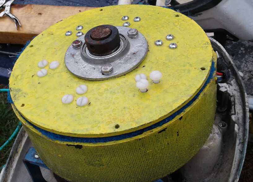
Electric Caik Outboard Motor
Trying the Caik outboard motor out again
on land after I returned from the test trip (early September), I had
trouble with the twist grip
'throttle'. I
dug out a slide potentiometer such as is sometimes used in stereos and
soldered on
the same 3 pin "trailer lights" plug that the twist grip used. I
unplugged the twist grip and plugged in the slide pot. The motor seemed
far more energetic. It spun up to over 3000 RPM (my estimated safe RPM
limit) in a flash at under 1/2
'throttle'. That seemed by itself to warrant another launch.
 On the 18th I
changed the magnetically
overheating metal bolts for nylon ones, a few at a time. That should
make for
lower current and less
heat - however slight the improvement might be. While a change in motor
heating would be hard to measure with
any precision, the RPM.s would be higher for the same currents because
of less drag on the rotor, so if the improvement was significant, it
should be apparent.
On the 18th I
changed the magnetically
overheating metal bolts for nylon ones, a few at a time. That should
make for
lower current and less
heat - however slight the improvement might be. While a change in motor
heating would be hard to measure with
any precision, the RPM.s would be higher for the same currents because
of less drag on the rotor, so if the improvement was significant, it
should be apparent.
The next test on the water,
on the 19th, didn't go well. I did remember to put the drain plug in
the boat this time,
and I brought the RPM (=Hz*30) meter and a voltmeter for motor
temperature.
But I had taken the new control (the main reason for the test) in the
house to keep it out of the
rain, and I forgot to bring it. I had also thought of bringing a
clamp-on ampmeter to recheck the calibration of the connected
one, but didn't. Its absence was soon sorely felt when the installed
one became intermittent and then just read zero. The only reading I got
was almost immediately:
about 10 amps gave 1140 RPM. And I hadn't taken one at 10 amps on the
previous trip, so no direct comparisons were possible. I puttered
around for quite a while at about 1650 RPM, which was as high as it
would go.
The motor seemed to get up to about 50 degree temperature
rise for a while. That was really as hot as I wanted the plastic motor
to get. I turned it down a bit and it cooled a few degrees. I turned it
up again and the motor started getting still hotter; 60 degrees rise or
more.
The coil heat could now be plainly felt on the outside of the composite
plastic case. Just before I got back to the boat launch - and for some
time afterward - I could smell the hot plastic. Did my motors heat up
that badly, and at such low power, probably a little under one
horsepower? This was very discouraging.
But the three coils at the back felt much warmer than the
three at the front. Since they must have all had the same currents
flowing in them, that meant the front ones must be getting better
cooling. With the cover having been off the outboard, I can only
attribute this to the forward motion of the boat wafting air in from
the front. That didn't say much for the magnets acting as a centrifugal
cooling fan! On looking at the picture of the improved rotor (TE News
#104), it was apparent that unlike the Hubcap motors, in the Caik size
the inner ends of the magnets were so close together as to restrict air
passage and perhaps almost eliminate "centrifugal fan" operation. Also
I looked underneath and realized the holes for the circulated air to
exit were pretty tiny.
So the motor probably wasn't making a lot of heat,
it just wasn't getting cooled effectively so the coils just kept
getting hotter. Somehow the problem needs to be solved or I might as
well give up making what I thought were essentially pretty fine motors.
At least the nylon bolts didn't heat up.
If I can solve it, maybe on the next try I'll try to get
it up to 70 or 80 amps ...and maybe even get the
boat on a plane before the 50 amp breaker blows - or the motor
controller blows ...or the motor wire insulation fries. If it does get
up on a minimal plane with one person on board, it's doing as well as
it did when it was a 7.5 HP gas outboard. Would I dare try?
Leftover Articles From the Past Summer
That really ends the September Month in "Brief".
But here are a few perhaps noteworthy belated items I left out
of the April-to-August newsletter because it was so long.
EV.s Pickup (Level towing)
This is really included for those who may have occasion to
tow a vehicle with "level towing" using a tow bar, especially
for the purpose of electric conversion. You've seen it done behind big
motor homes. I did it behind a Dodge Caravan minivan. (A vexatious and
costly feature, at least in BC, is that the towed vehicle must be
licensed as if for driving it.)
On May 26th the monthly North Arm Transportation barge
reached Masset and unloaded my electric vehicles: the Swift, the Miles
truck, and the Sprint project car. Tom and I drove up to get the Sprint
and the Swift that afternoon. The normally deserted North Arm yard was
a hive of activity with huge trucks picking up cargo.
Someone had hit the "kill switch" breaker in the Swift and
so the gauge didn't know how much charge there really was. We charged
it for a bit with a gasoline powered generator I had purchased before
leaving Victoria. In a bit it looked like it must be pretty full.
We connected the tow bar to the Sprint and hooked it to my
Dodge Caravan. (...the minivan retrieved from its breakdown point south
of Quesnel
by Tom the previous week. The rescue took him a whole week, with the
long distances, and the bus and ferry schedules being unfavorable. And
it cost me 1400$ for his expenses. Ouch on both counts!) In a brief
test, the Sprint seemed to tow well, so I drove, towing it, behind the
Swift. I stuck to about 60-70 Km/Hr towing the car, and Tom also kept
to those speeds. That was probably well given my next towing eperience.
It was about 37 Km from the barge landing point to Port
Clements - about the range of the Swift to keep the batteries above
50%, and it was also the half way point of the 76 Km trip. Tom drove it
to a shop there whose owner he had previously met, with the gauge
saying 52% charge remaining. We plugged it in for the night and drove
home, both in the Caravan again. We unhooked the Sprint, washed the
salt spray off it, and put it in the garage by the workshop. I was glad
to get some of the supplies I had stashed in these vehicles, especially
the electric chainsaw, the wheelbarrow for gardening and a kitchen
table and chairs.
The next morning I went back to the barge landing to get
the little Miles electric cargo van. At the half way point I dropped
Tom off to drive the Swift the rest of the way home.
I figured it would be folly to try to drive the low speed
(max 40 Km/Hr) Miles, with unknown but surely insufficient travel
range, on the highway with the traffic (little tho there is) doing
80-100, and very narrow shoulders to pull over onto. Back in Victoria I
had found a quick way to hook up the tow bar. The other requirement for
towing was to disconnect the transmission from the wheels. Otherwise
the motor would be seriously over-revved at higher speeds and might
well fly apart.
Things started off well. I backed the Miles onto a couple
of ramps that were inside it. Surprisingly the 4 bolts holding the
drive shaft to the differential came out with no trouble, and I wired
up the shaft so it wouldn't fall down. But I couldn't push the truck
off the ramps as they sloped a bit and it was uphill. I tried to pry it
off for quite a while, unsuccessfully even using a peevee and sticks of
wood to keep it from rolling back, before I realized there was a better
way. I drove to Masset where I needed the chain-gate key to get
vehicles in and out of the yard anyway, and borrowed a rope.
After pulling it off the ramps with the van and rope, I
put the tow bar on. Here it turned into a fiasco. I turned and the
Miles didn't seem properly centered behind the van. I drove up the
drive and across the highway from the yard to the North Arm office
driveway and stopped there. The little truck moved from centered to one
side behind the van. Something certainly wasn't right.
I found the links to the tow bar were all bent up, also
the body metal they were bolted to. Using what I had had and pressed
for time, I had used some pretty light steel brackets that doubtless
should have been heavier, and attached them at dubious points where
there were convenient holes instead of at the strongest parts of the
truck's frame. But I think my worst mistake was that the arms of the
tow bar were too close together, attached too near the center of the
vehicle. Instead of the equalateral triangle I had had on the Sprint,
it had a narrow base. That meant that when I turned, there was great
force pulling on one arm of the tow bar, and pushing on the other.
I crawled underneath and bolted the driveshaft back on
(hadn't needed the ramps after all!), then drove the Miles back into
the yard. I returned the gate key and the rope, and told Masset
services they would have to deliver the Miles on a truck for me. That
would cost a bundle, but I didn't fancy my prospects of making and
installing a new and improved tow bar linkage in a yard far from home
with only whatever tools and materials I thought to bring with me,
especially when (eg) I already knew I was missing all the angle
grinder's attachments. (...probably in my trailer, stashed in Cache
Creek.)
I drove home with just the kitchen chairs, peevee and a
firewood splitting maul for prizes. At least the Swift was there,
washed and thoroughly cleaned inside and out by Tom after he got it
home.
After about 10 days of looking for someone to deliver it
on a trailer (and some unreturned phone calls), on the third Tom and I
were part way to Masset on other business and decided to drive up
(another 40 Km each way) and look for some better way to attach the tow
bar. I bought a couple of overpriced zip disks for the angle grinder in
a hardware store there. Under the hood of the van at the barge landing
we spotted some
vertical square tubes with open sides (easier seen than described, but
alas the pictures were on my old cell phone) in
the frame about the right distance apart, out near the sides of the
cab. I figured one might insert a couple of plates and bolt the tow bar
up into them. We made a checklist of things needed or possibly needed
as we drove back. (This was well, or we'd surely have forgotten several
important or potentially needed things perhaps including the key for
the Miles. In the event, the only thing we forgot was the safety chain
for towing.)
I made and drilled the plates from 1/4" thick aluminum
scrap the next day and we drove up to rescue the Miles. Considering we
had had no tape measure or anything, I had sized the plates perfectly
and I
just had to cut a couple of small notches in them with a hacksaw when I
went to fit them in place. Once everything was ready, we hitched it up
and this time it seemed to drive well. It was certainly heavier than
the Sprint, with the better part of 1000 pounds of golf cart batteries
in it as well as the greater vehicle weight itself. At a good pullout
after a few kilometers, I stopped to check things in spite of Tom
saying "Drive on, don't stop!" I yanked up on the tow bar... and it
came right off the hitch ball! Yikes! (and with no safety chain!) The
latch needed adjustment, which is accomplished by simply winding a
locking nut up or down a bolt underneath with a socket wrench. That
accomplished, we drove on. We arrived safely after towing the truck the
whole 76 Km at 45-60 Km/Hr.
I suppose I must have towed the Sprint home with the same
precarious hitch maladjustment. However, the tow went without a hitch.
NiMH Battery Stick Fix - Duh!
Two of the tubes in one "quintos" set didn't make contact, the
cells rattling slightly between the end terminals. They probably got
knocked about a bit by waves on the barge at sea on the way up, denting
in the "-" end of one or both cells a bit. With the tube ends being
glued in, I never previously saw any way to fix such tubes except to
break an end off and re-glue it. This time it occurred to me that the
stainless steel connection bolts were threaded through the plastic
ends, and done up tight. If I loosened the outside nut and gripped the
protruding threads carefully with pliers, I could turn one end bolt and
wind it in until the cells made good connection again.
That annoyance was my biggest reservation about the glued
tubes, so I like them better now!
The Swift fire of course was a separate issue, but one
that brings battery safety and problems with overcharging to the fore.
I think perhaps the tubes would be best placed in a metal box. Of
course, they are best off not being overcharged. I'm thinking of
putting in a charging relay with every set of batteries that will cut
off charging for 1/2 an hour if the charge voltage exceeds some
threshold, regardless of what a charger 'wants' to do. If it keeps
trying to overcharge it, the cutout will keep getting tripped, even
almost immediately, as needed. And maybe for NiMH.s it would also be
temperature activated. This shutoff would especially apply to charging
directly by unregulated solar panels, eg on the vehicle roof as I plan
for the Miles cargo van.
Solar Panels for the Miles EV Cargo Van
When I checked out trying to use the 36 cells, 90 watt
solar PV panels to charge the van, it appeared that the voltage would
be just a tad too low to use 4 in series for a float charge. Having got
the 100 W panels, they seemed just that tad higher voltage. Not only
could it work with 4 panels instead of 5, but these 4 shorter, wider
panels would fit within the roof area of the van, where the 90 W ones
would have stuck out over the front or back.
I could either hook up each panel separately to 18 V worth
of batteries, or connect all 4 in series to the lot. I prefer the
separate charging, but to put in the shutoff would then require 4
separate shutoff units. Anyway, all theory as I didn't get it done.
Lead-Salt, Lead-Alkaline Batteries - Belated Revelations
I'm not sure I've said this in any coherent fashion in one
place before, so I'll stick this note in. It's interesting how
little, unsuspected things can change our perspective. A great example
would be the wrong reaction voltage for lead oxide or sulfate to lead
dioxide in alkaline solution, that someone mistakenly printed on a
chart, saying +2.47 V instead of +0.47 V. This chart led me to
misunderstandings, confusion and wrong conclusions about what would
happen to lead batteries if they were changed from acid to neutral or
alkaline, for the whole of the time I was experimenting with them. It
never occurred to me that chart might be wrong. (In acid it's +1.71, so
+2.47 didn't seem out of place to me. But in fact, only at the acid end
do the voltages rise up.)
Only much later did I dig up a pourbaix diagram that
showed the correct values, and then the mysteries were explained. The
battery voltage drops from 12 to 6 volts as pH rises from 1 to 6.5 and
is relatively constant above that, instead of the reactions becoming
impossibly high voltage in alkaline aqueous solution, where it would
bubble away
the water without charging the lead. And the problem with lowered
voltages - other than even lower energy density - is that lead-acid
battery chargers will keep trying to get
them up to pH 1 voltage, and fry them with overcharging.
So the batteries can be renewed with a small amount of
sodium sulfate, or they can be converted to "lead-salt" batteries
having a lower voltage with a large amount. Since the renewal causes
sulfate crystals to come off the plates and reconstitute sulfuric acid
and dilute the Na2SO4 to acidic NaHSO4 (also pH 1), it's most likely
going to be a compromise at some voltage between 8 or 9 and 11,
depending on
relative concentrations. At least, those were the voltages I was
getting without understanding why they were lower. The less acidic
batteries can be made from
scrapped batteries and will probably last a long time. The issues
become how to charge them, and for transport applications, needing more
of them to attain the desired voltage -- the additional
weight per energy stored.
Electric Sawmill Rides Again - NOT!
I made an electric swivel blade sawmill in summer 2006.
There was a snowstorm of heavy, wet snow that autumn that brought down
big trees all over town, and from that initial collecting I cut
specialty hardwoods from local trees people had taken out or which died
or came down in storms - a 'hobby business', mostly for about 3 years
2007-2010. (But the stock doesn't move very fast: it was much thinned
out, but I was still selling occasional bits of wood in 2017.) An
electric sawmill is nothing new, but it's much 'greener'
than a gas mill. I made mine from a burned out 7.5 HP, 3550 RPM motor
that I rewound to run single phase on a dryer outlet, using 16" table
saw blades that could be purchased anywhere. The last time I milled was
2011 or 2012 - some small ornamental cherry tree logs dropped in my
driveway by Davey Tree Services. I had thought to sell the mill then,
but I hadn't, so I brought it with me in the move, and for once it
seemed all the parts had arrived and none of it was back in U-Pak
storage in Victoria.
Then I had the big spruce trees taken out, and Tom was
having them turned into 6x6 beams by a new friend from Tlell with an
Alaska mill, in trade for doing work for him later. The logs as such
were too big for my little mill even if we could have moved them, but
anything cut by the chainsaw mill became a good size. I called around
to see if anyone wanted to rent me a small sawmill but I got no
affirmative responses, so I set up my mill on June 25th outside the
laundry room window. If I didn't need the lumber, I could at least sell
it. I oiled the many moving parts and 'repaired' the cooling water
bucket (it would still leak), and turned the motor on to test it. It
ran, so I got a log piece, set it up, and made an exploratory cut to
check the cut height. All went well; everything was ready to slice the
piece into three 2x6es!
The next time I turned it on, it blew the (dryer) circuit
breaker as it started. After that, it wouldn't start. Something had
gone wrong in the startup part of the circuit - switch, starting
capacitors or starting coil windings in the motor. It was as if I wan't
pressing the switch. I opened the connection box and the switch seemed
okay on a meter. There was a rather loose connector to the capacitors,
but tightening it didn't help. It was the end of the day and rained a
few drops, so we put the mill away in the garage, leaving the tracks
set up. Ug! It wasn't a very auspicious start to starting to use the
mill again after so long! Another day I opened the box and found &
fixed a bad solder connection. It started turning, but still wouldn't
come up to speed and blew the breaker again. Now I suspect the startup
circuit wasn't the original
problem. There might be burned out wires in the main 'run' circuit - a
problem I had had to occasionally deal with by cutting the burned ones
and threading a few new ones in. Having been inexperienced with motors
when I first wound it, I had made the 'overhangs' too long and they
vibrated and eventually shorted out. (The only way to permanently fix
it
would be to start over. And I don't think there's a motor shop with a
motor varnish dip and oven here.) I would now have to take the motor
apart
and check things out more thoroughly. But I had no magnet wire here to
repair it. I pulled up the tracks and put them away. I'd like to rent a
bandsaw mill or buy a used one.
Note: Around the time I moved I had been thinking of
buying
a low cost "Woodland 722" bandsaw mill, but didn't. Like mine, you push
the saw along the track by hand. In September someone told me he had
one but that it was laborious and troublesome and he was always
repairing and
adjusting it. Until and unless I can find something that's affordable
and also substantially better, I might as well repair and stick with my
homemade electric!
In Passing
(Miscellaneous topics, editorial comments & opinionated rants)
A Bit More Perspective on the Evolution of Life
A while back (TE News #100) I wrote of the idea that the
creatures of the
Permian period were amphibians, not reptiles as has been commonly
supposed. It appears to me that reptiles didn't evolve until the end of
this period. Where it
was mentioned at all in the literature I found, the bone microanatomy
of such creatures as Dimetrodon and Bradysaurus support this theory.
From a timeline perspective it makes perfect sense. First
were probably phytoplankton and then multicellular pre-Cambrian
vegetation, then it gradually made a transition toward becoming animal
life as evidenced by the strange Vendian/Ediacaran period "transition"
fossils. In the Cambrian the first true animals
arose, the many varieties of trilobites and their cousins. Then there
developed various
cephalopods, brachiopods, arthropods, ammonites and so on (Ordovician,
Silurian),
followed by fish of increasing sophistication (Devonian).
Meanwhile plants had gradually crawled ashore, and by the
Carboniferous had covered the land in a magnificent verdure of fern
forests, which started consuming the carbon dioxide that choked
Earth's primitive air and
converting it into
coal and oxygen. Some suggest that the oxygen levels became higher than
they are today, but there was surely still too much carbon dioxide for
higher animal respiration in the early Carboniferous. Arthropods
however came onto land, starting with sea scorpions whose swim bladders
had evolved into lungs, and in the absence of any higher forms of
predators, land "bugs"
grew to enormous sizes, such as dragon flies with 30 inch wing
spans, giant cockroaches and millipedes several feet in length.
As the carbon dioxide levels decreased, certain vertebrate
fish that had evolved along favorable lines started crawling ashore as
adults and breathing air - they became amphibians. It appears there
were two branches: those that became newts and salamanders, and those
that developed into the frog family. As with the earlier insects, there
were no higher life forms on the land to devour these moist, soft
bodied
amphibians, so they grew to dominance and large sizes. Eryops types of
'salamanders' grew to 4 feet while Dimetrodons and Edaphosaurs started
at 6 or so and eventually hit 10 or 12 feet. The larger insects now
perished, doubtless into the jaws of predatory amphibians. Insects
could no longer dominate the land.
The larger early amphibians grew
large "sails" on their backs to help expel carbon dioxide from their
bodies, especially as the air was still only marginally fit for
breathing (see TE
News #100). It
improved until by the early or mid Permian there was little carbon
dioxide in the air. Apparently the awkward sail backed creatures were
then
"obsolete" and died out as more aggressive and advanced species arose.
Still they were all amphibians that probably grew from tadpoles when
they were young. They had soft bodies and lived near water - even land
life was still largely water based. Then in the
mid Permian, the seed plants evolved, and for the first time afforded a
good land based food supply for animal life.
After that, new types started to arise, culminating in
"pre-reptiles" such as the Dinocephalia and the Bradysaurs, probably
evolved from the frog family, including the upright postured
Bunostegas. Many of these were said to be "the size of a cow". Still,
these
large, sluggish amphibians thrived because there were no
higher types of predators.
With increasing land elevations, the world's salubrious
climate started giving way to the continental type of climate, and
widespread aridity. This caused an era of severe biologic tribulation
toward the
end of the Permian wherein most
species died off the whole face of the Earth including in the seas.
(Something like 95% of all species?) Being able to travel across land,
the frogs and
higher amphibious pre-reptiles survived even around the drying pools.
The stage was now set, and at the end of the Permian,
true reptiles appeared on the scene, real land animals, and rapidly
branched into various families. Fierce early types such as the
saber-toothed Gorgonopsids made short work of their larger amphibious
and pre-reptilian ancestors. Amphibians could no longer dominate the
land, and like the insects before them, only
small bodied or specialized branches found ecological survival niches.
(Was the sail-backed Cretaceous period Spinosaurus, living in a
unique ecology of north African swamps, a giant Dimetrodon-like
amphibian? Where are the breastbones? What does the bone microanatomy
say? I digress again!)
It then follows that after the Triassic, Jurassic and
Cretaceous periods of reptilian dominance, with the rise to
dominance of the birds and then more especially the placental mammals,
the
reptiles could no longer compete on even terms. They lost the
struggle for dominance and again, only those branches which found
specialized niches survived. Birds at first, and then mammals dominated
and some attained huge sizes as the Cretaceous gave way to the Eocene.
(For the most extreme example, a human could have
walked underneath an Indrocathere [SP?] without touching it.) All the
dinosaurs, the sea monsters, and the flying reptiles perished in a
relatively short time.
All these advances of evolution seemed to occur as a
logical progression, virtually a programmed sequence. It seems that the
first
plankton had the same genetic DNA structure as all the later forms of
life, and no doubt this DNA could be programmed to evolve into any form
that it did evolve into, and countless other forms if the environment
had been more favorable for that. No "snowball Earth", continental
scale lava flows, or giant meteors are required to explain the
glacially slow but continuous progression of life from the most
primitive to the more advanced.
(BTW, my vote for the first placental mammal is the rather
kangaroolike, carnivorous Leptictidium. This creature is known from the
late Cretaceous and wouldn't have been much of a change of form from
some small, kangaroolike, carnivorous dinosaur, perhaps Troodon. But I
digress again!)
Evolution of brains also proceeded and increasingly
brains and not huge size constituted fitness for survival, and the
larger mammals with small brains of the Eocene gradually perished. With
the
proportionally largest brains and the development of attributes of free
will, worship and wisdom, humans have attained dominance and
caused a great wave of extinctions of other
species which has increased in scale and reached a fever pitch in the
last few hundred years. Some European plant and animal species were
saved to the present day only by making "royal" lands on which hunting
and wood gathering (or even being present) were punishable by death.
Some "common" game animals
like deer were
hunted to rarity in the USA in the great depression of the 1930s. In
the coming time of crisis, with triple the population of that
time, the planet is almost bound to soon sustain terrible losses of
species. (Word has it that 2018 will be a very rough year of
economic depression for the 99% and a globally increasing crescendo of
"natural"
disasters - which seem to have already begun with more record droughts
and bigger forest fires, more record flooding, even stronger
record-breaking hurricanes, even higher record temperatures, and
powerful earthquakes.)
A Whole New Understanding of the
Second World War?!?!
I thought that I, and everyone, understood what the Second
World War was about
pretty well. But if what Victor Suvarov writes is true,
it seems the biggest story about the ideas and plots behind the theme
and events of the war has never been told. It would appear most of us
today
have a profound misunderstanding of the main causes and hidden motives
behind it.
The war as we understand it has deep puzzles if too
closely examined. Why did
Hitler suddenly switch from simply demanding Danzig, a German city in
Poland, to
reconnect East Prussia with the rest of Germany, and instead invaded
Poland in an all-out assault? Sure he made an agreement with Moscow,
but was he really so naive as to think that
Britain and France would abandon their strongly worded pledges and not
declare war if he attacked Poland? Then, why did Germany attack the
Soviet Union without ending the war in the west, when every school kid
in Germany knew that a two front war was almost surely suicidal? And
why were the Soviet forces so badly arranged and prepared when a German
attack was the only and obvious threat to prepare for? One
shrugs and figures Hitler must have been nuts... and the Russians
incompetent... but it seems there was
method behind the madness, and a hidden agenda no one in the west saw,
behind the
outward appearances. Hitler, it would seem, for all the havoc that he
accomplished, was just a pawn in a larger
chess game!
I accidentally found a book on line, written by Russian
researcher Viktor Suvarov (publ. 1990), which absolutely
revolutionized my entire understanding of the war. It was titled Icebreaker:
Who
Started
the
Second
World
War? In this thoroughly researched
book which cites many documents and news articles of the day, we learn
that almost from the close of World War One, the Communists decided
they
needed to start another war to "liberate" Europe from the fetters of
capitalism and convert it to communism. (Suvarov also appears on
youtube in speaking engagements on the subject, and there are
corroborating works by other authors if one searches for them.)
Lenin's overarching plan for the new war, then furthered
by Stalin (a seven times escaped bank robber - that's how the Communist
party was funded), was to get Germany to
start another war and embroil Europe in a new conflict, again
devastating to
all sides. Germany was to be the "icebreaker" to break up Europe, which
would then be so weakened as to offer little resistance when the
liberating armies of (Russian) communism came to put an end to the
misery and bring peace to the shattered continent. So Germany and
Hitler, moved by their own lusts for power, triumph
and glory, were intended to be unwitting pawns of Russia. The country
that entered the war last, after all the others lay in ruins, would be
the victor. World communism was the final goal. The soviet coat of arms
didn't show Russia with the hammer and sickle - it showed the globe.
It is important to realize that Russia was only step one in the
unbounded enthusiasm and ambition of
the new communist philosophy, which had widespread support from large
masses of people. In the early 20th century it was considered by its
proponents to be the "manifest destiny" of communism to overthrow all
other forms of government, everywhere, and rule the world.
So planning for World War Two really started in Russia
with the Bolshevik revolution. Lenin saw the chaos of The Great War in
Europe as an opportunity to destabilize the nations there and replace
their governments with communist ones: the workers would rule, striking
down the bourgeois capitalists and rich enslavers of the masses. Russia
was only to be the first of many soviet conversions.
It is hard today to remember or to think about a time when
industrialism and to a large extent capitalism were still pretty new,
when previously rural peoples had been moving from the country to the
cities, and working
conditions were miserable. Even
children were treated horribly, sent to slave in mines and factories
with little pay for long hours each day. Out of this misery, underpaid
journalist Karl Marx
conceived communism, where the workers would throw off the yoke of this
terrible slavery and take the reins of power from the heartless
capitalists and industrialists. When the Bolsheviks seized power by
force in Russia, these ideas of communism were new, and its professed
tenets held sway in the minds of common and uneducated people to the
point that many would aid and empower the state to take whatever
actions were needed to bring about its rise. In the Communist view the
ends justified the means, but once the whole world was communist, the
harsh measures needed to bring that about would somehow end and there
would be a universal workers' paradise. Before that, any amount of
central power and oppression, of attempting to overthrow governments -
and not to exclude offensive war - were all cards to be played to help
attain the final end. That means are ends in the making
wasn't clear to common people of that day.
The Comintern was set up in Russia to help foment
communist
revolutions abroad. It was essentially a declaration of war on the
whole world, stating that communism aimed to convert your
country to their system by any means, peaceful or (more likely)
violent. But the war
had ended and by 1920, it had to
be recognized that the subversive Communist elements within the nations
of Europe, while active and influential, had been unable to bring about
their collapse and conversion.
Lenin conceived at that early date that a "second world
war" would be required, and envisioned the "icebreaker" strategy. From
1923, the German military, hobbled in Germany by agreements with the
victorious western allies not to rebuild its military, was invited to
rebuild and
retrain
within Russian territory. They were shown tank and aircraft factories:
"look, remember and copy". Russia supplied copious volumes of goods and
vital war materials to assist Germany with starting and prosecuting the
war right up to
the day they were themselves attacked. That was how German military
might was revived, not directly under the noses of the British and
French, but away from their gaze in communist Russia. Then, Russia knew
Germany
would need a mad leader to start another war. I confess to skipping a
few chapters where details may have been supplied, but helping to
foster
someone like Hitler's rise to power definitely fit the
Russian/communist agenda and plan. Nazism might also have been fostered
in Germany in
part due to fear of communism: better an extreme
authoritarian government than risk letting communism take root! But I
can't pretend to know the psyche of those days.
In all this Europe including Britain and Churchill were
evidently to
a large extent duped. They didn't trust Russia, but they also didn't
seem to see beyond the immediate threat of bad guy Hitler and Germany
to the long premeditated plan that had ultimately fostered that threat.
Let us turn now to the start of the war. It has been said
that Britain and France, not trusting Russia, failed to come to
effective alliance terms with them to prevent the war. I think this may
now be
seen as probably not a simple failure of western diplomacy and policy,
but also
because the communists didn't want to be allied with the hated
democracies anyway and would have been
negotiating insincerely - and then of course they would blame the other
side
for failure to reach an agreement. For example, they claimed to be
"offended" that Britain didn't send someone more prominent to do the
negotiating. ...is that a reason to not negotiate if you're trying
desperately to maintain the peace? Anyway, western mistrust of Russia
was doubtless realistic.
Hitler had been demanding a corridor
through Danzig in Poland to East Prussia, which was a piece of Germany
not connected to the rest except by sea. Stalin said, "Why settle for
the corridor?
Why don't we divide Poland between us?" The Molotov-Ribbentrop pact to
divide Poland and profess German-Russian Friendship, of August 23rd,
1939, was not a desperate measure to appease Germany because of the
failure to come to agreement with the west. It is well known that it
was this agreement that gave Hitler the nod from Russia to invade
Poland. But Russia realized that. It was in fact a clever ploy
to get
Germany into a war with the west. At the same time it would create a
common frontier with Germany in order to be able to launch a surprise
attack on it. Hitler for his part didn't want war with the west - at
least not while Russia was a threat in the east.
Everyone
knew Germany was in the middle and a war on two fronts would be
suicidal. But he also was eager for a common frontier - in order to
attack Russia. In addition to "Lebensraum" for the German people, the
threat of communist Russia overrunning Germany and all Europe was a
real one. The two odious governments mutually hated, wanted and
expected to
eliminate each other.
So on September first, Germany attacked Poland. Hitler
didn't just gamble that the western powers would back out of their
agreement with Poland. Surely Russia's simultaneous attack on eastern
Poland per their agreement would confuse, diffuse and deflect the
criticism. But once Germany had already attacked Poland, Russia
informed him
that the Soviet armies weren't ready yet, and they didn't attack.
Stalin had tricked Hitler (and it is recorded that he said so) into
looking like the one very aggressive aggressor,
and into embroiling Germany in a war with the west. Since the two
powers never had any intention of living in peace with each other, he
had already in effect tricked Hitler into starting the fatal two front
war. From that very first day, Germany and Hitler had lost the war -
unless
they could negotiate peace with the west, or defeat France and drive
Britain out of
the
war or conquer it. Peace was not offered. What remained was the
attempt. Hitler was confident he could defeat France quickly, but he
underrated the remaining difficulties: the resolve of Britain,
and the obstacle of the English Channel to advancing armies with the
power of the British navy to defend the crossing. (Many think Germany
could have invaded Britain in 1940 if they had tried. They are not
aware that that summer Britain sank in port about 1/3 of all
the shipping Germany was trying to collect in the channel to invade
with, by naval and air attacks. To illustrate the almost inevitable
outcome: Later, in the shorter crossing to attack Crete, Britain sank all
of the German troop ships, drowning many thousands of men. The invasion
of the almost undefended island succeeded only by sacrificing the only
German airborne division, who took an airport to land reinforcements
at. And all the harbors were on the wrong side for Britain to land
reinforcements. Such a weak German assault even on 'naked' Britain in
early July 1940 would have been quickly mopped up, and every week the
defenses became stronger and better organized. But I digress.)
By the time Russia moved into the eastern side of
devastated
Poland on September 17th, it was accepted by the west to be a
reciprocal move in response to Germany's attack. Indeed, while Hitler
fought in western Europe, Russia's takeovers of Estonia, Latvia,
Lithuania and a considerable territory of Romania (Bessarabia) were
excused as being necessary to fortify Russia's defensive position
against the
Nazi aggressor. In reality Russia had created a long common border and
(especially)
was now ready to strike quickly at Germany's only source of oil in
Romania, and
thereby at its throat, at any time of its own choosing. Once
attacked, Germany might have tanks and
trucks, but it would have no fuel for them. It would surely succumb
quickly.
The main events of the war as they occurred are well
known. The reasons for some of them are what have not been understood.
The Polish campaign, despite Germany's resounding
military success, didn't go as Germany had expected. If Russia had
attacked Poland on the same day as Germany in accord with their
agreement, what would have been the reaction of the west? It might be
expected that it would have been substantially different. The guarantee
was to protect Poland from aggression -- only implicitly "from
Germany". The western allies might well have paled at declaring war on
both Germany and Russia.
We now turn
to the German invasion of Russia in 1941. When France fell easily but
Britain
couldn't be cowed or invaded, the
hoped for (by Germany) end to war in the west couldn't be attained, and
the hoped for (by Russia) destruction of Europe essentially didn't
occur,
and the
Russians had little to gain by waiting. They prepared a gigantic
blitzkrieg to overrun Germany and Europe, on a scale and perhaps at a
speed that dwarfed the ones in Poland and France. It was even larger
than Hitler's "Barbarossa" attack. They had many thousands of tanks
that would shed their tracks and race over the German autobahns and
other good paved roads of Europe on wheels at 100 KmPH. They had
copious aircraft designed to strike down everything that moved behind
German lines. They started an immense movement of troops, munitions and
equipment in the spring of 1941 and placed it all just behind the
frontier. Britain knew of the massive German troop movements toward
that front from reading broken German Enigma code transmissions, but it
didn't know of the Russian buildup. According to Suvarov, the intended
start date for "Operation
Lightning" can be
derived from the movements and other evidence: Sunday (always pick a
Sunday morning when westerners were in church!) July 6th, 1941. As it
turned out, there was a fly in the ointment: Hitler attacked
them first by just two weeks on June 22nd, 1941.
Again Hitler seemed like a mad aggressor, this time bent
on
repeating others' mistakes and starting the fatal two-front war. In
fact, it was a desperate attempt to salvage the position of what was
already in principle a two front war. The mistake had already been
made, in 1939
with the attack on Poland while Russia, in violation of the agreement
just made, held back. In the Nuremberg
trials, generals Kietel and
Jodl both insisted that the attack on Russia was a preemptive strike,
designed to start an inevitable conflict on more favorable terms than
by waiting for the Russians to start it with an attack that would
immediately cut them off from their only oil supply. Westerners didn't
believe them, but the Russians knew it was the truth. They tried to get
the generals to change their story, but they never did.
How was it that an attack just two weeks before Russia's
own intended attack initially fared so well and so disrupted the
immense Russian armies? Both sides had set up for offensive operations
as close to the front as they could get. They had no defensive depth
and
had prepared no defenses. Even defensive works Russia had previously
had had been dismantled and pulled to the front to bring more power to
bear for the offensive.
Suvarov believes that if Russia had attacked two weeks before Germany
did instead of the other way around, the Germans would have been
equally caught with their pants down and would have been easily routed.
And Germany, without immense stretches of land to retreat into, an
immense peasant population to draw more soldiers from, and blocked from
access to oil, would have been
quickly defeated. The rest of already crushed Europe would be a
cakewalk.
Russia's powerful offensive weapons were wasted. The fast
tanks that would have spread the attack and chaos so quickly through
western Europe were useless in Russia itself where there were no paved
roads. And the Russian planes were
built to attack ground targets, not to fight other planes, again making
them of little value for defense.
Instead of preemptively destroying the German air force on
the ground, it went the other way around. And wherever the Germans
broke through, they could quickly surround the masses of Russian troops
crowded along the frontier and cut them off from their supplies.
Of course, once Barbarossa
had been launched and Germany
was driving deep into the heart of Russia, Stalin cried "Poor innocent
us, we were attacked without provocation and without warning, and were
of course completely unprepared for this German treachery!", as he
demanded help and a cried for a "second front now!" (invasion of Europe
from Britain) from the
"decadent", "bourgeois" west that the communists had
vocally consigned to rack and ruin right until that moment,
congratulating
Germany on every victory.
Hypothetically, what would have been the reaction in the
west if mighty Germany, victor over France and having just overrun the
Balkans and Greece, seemingly invincible, had been itself suddenly
invaded and
quickly overrun by overwhelming Russian communist forces,
which
then continued right on to the Atlantic coast? Would
they have suddenly adopted a more German-sympathetic point of view? The
question might have been irrelevant, because there would probably have
been
little they could do about it. I think we may be glad that events did
not take this course. It was more helpful to human freedom and
progress, and one might feel more fitting, that the two mighty
dictatorial powers battered away at each other for four long years,
with the original schemers who would invade and lay waste to Europe
becoming themselves the invaded party and substantially laid to waste.
How was it that the Russians were
so convinced that the
amassed German armies wouldn't attack, until the day they did?, that
they would have time to ready their own strike without interference?
There were two factors. First Stalin simply couldn't believe Germany
would start a war on a second front when they were still fighting with
Britain - or at least he fervently hoped not. (When Churchill asked
Stalin about them sending war supplies to Germany right up until the
day of
the attack, and ignoring Churchill's own warning - wasn't it evident
the
Germans were going to attack
them? - Stalin blandly replied "I thought we would have more time."
What
he didn't mention was that he had only needed two more weeks to ready
his own offensive, and then it would have been too late for Germany -
and Europe.)
Secondly, Russian spies reported
that Germany, in spite of the
troop buildups, hadn't taken obvious necessary preparations to attack
Russia. The oil being used in their tanks would congeal in cold Russian
weather, and they hadn't started changing it. And they hadn't ordered
the millions of lambskin coats the troops would need for the cold
Russian winter. The price of lamb and of lambskin was still the same.
But if Suvarov is right, battle was imminent, one way or
another. Germany decided it might as well attack first to start it on
more favorable terms, and fooled the Russians by attacking without
making
these
obvious
preparations. Whether that was genius or stupidity, their lack was
apparently instrumental in achieving initial complete surprise. But the
winter was then devastating to the German army.
Stalin didn't get Europe. After four years of bitter
struggle that devastated the Soviet Union with the rest, he got
half of it and was thus the only "victor" of the war in terms of
territory. But he was forced
to
agree to a line of occupation with the hated west, which now included
America. Instead of a weak force of devastated Europeans, a now
powerful but devastated
Russia was faced by a huge allied invading army of rugged, relatively
fresh
troops, which in many places had passed the agreed line and had to be
withdrawn to it, the Russians humbly moving into the territory as it
was vacated for them per the agreement. And almost immediately those
allies had the
atomic bomb, so assailing them would have been suicide even after they
had withdrawn most of their troops and Russia had recovered. And (tho
it took power in China and other places) the ideology of communism was
making few
new
adherents. Surely everywhere people must have
been doubting it was the "manifest destiny" of communist workers to
rule the world or that that would be desirable. Russia didn't seem to
be the promised workers' paradise under communism. The last soviet
leader
to claim "We will bury you." (i.e. 'We will outlast you.') was Kruschev
around 1960. In spite of a few very serious scares, the rest of Europe
proved to be safe until the ideological
struggle had run its full course, until democracy took hold in the
Soviet Union, communism was outlawed, and then the union itself broke
up.
Churchill's "Iron Curtain" speech ("From Lubek in the
Baltic to Trieste in the Adriatic, an iron curtain has descended
across the face of Europe. Behind this line we are not permitted to go
or to see..." [quote wording unchecked]), was widely said to have
kicked off the cold war. Or perhaps more correctly, it finally
acknowledged its existence. But everybody was quite sick of war by the
time hostilities ended, and it probably also did much to help keep it
cold when
he also said, after lamenting about Soviet Russia's actions and
intransigent
attitude, "I do not believe war is inevitable; still less that it is
imminent."
Okay, everybody relax!
Newsletters Index/Highlights: http://www.TurquoiseEnergy.com/news/index.html
Construction Manuals and information:
- Electric Hubcap Family Motors - Turquoise Motor Controllers
- Preliminary Ni-Mn, Ni-Ni Battery Making book
Products Catalog
(Will accept BITCOIN digital currency)
...all at: http://www.TurquoiseEnergy.com/
(orders: e-mail craig@saers.com)
Electric
Transport
New Chevy Sprint Conversion
I spent time toward the end of September disassembling or looking at
the two transmissions I had lying on the shop floor, and trying to
think of ways to use them to get something better than just a fixed
ratio with low starting torque and a low top speed. Below I've written
these explorations up. But every path I started down that seemed
promising at first seemed to get more complicated the closer it was
examined and the more I did on it. They were pretty much fixed
internally and they took up too much space to allow extra components to
be added.
Finally in October I decided to try one more time to do my
own variable transmission "from scratch", this one seemingly
straightforward and with belts only. But that's for next issue. I
considered deleting "Various Transmission Explorations" as being pretty
long and boring, but perhaps it could be useful to someone looking for
ideas.
Fiddling around and looking transmissions over was a
relatively easy project with no further commitment. But of course it
led to formulating a plan for proceeding, which would then become a
long project. I see I can once again easily be distracted from the more
impressive projects by the more immediately useful. I decided to put
the ground effect craft on hold until I'm driving electrically again on
land. With a known good motor and controller, and a simpler variable
transmission design, it shouldn't take too long. (Ha, ha!)
Starting the Project
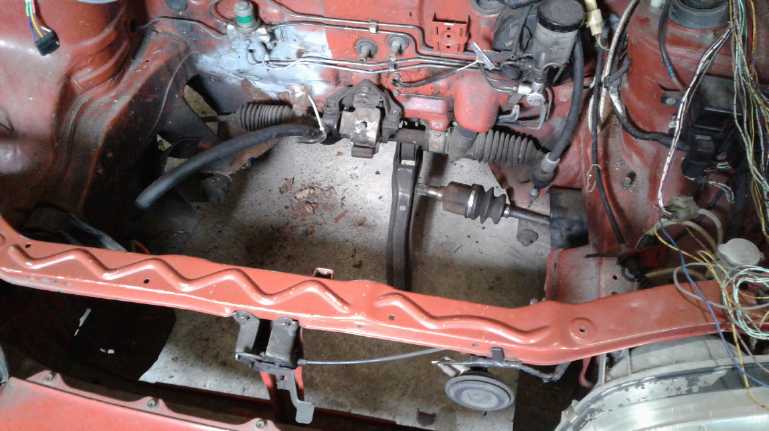 On the 25th I
dismantled everything under the hood
of the Sprint, removing the Hubcap motor, transmission, mountings,
motor controller plate and the right drive shaft. I installed the left
drive shaft, the one to fit the planned new geometry at that time. Then
I went back to
working on the transmission.
On the 25th I
dismantled everything under the hood
of the Sprint, removing the Hubcap motor, transmission, mountings,
motor controller plate and the right drive shaft. I installed the left
drive shaft, the one to fit the planned new geometry at that time. Then
I went back to
working on the transmission.
Another thought occurred to me: that if I was going to use
the same Curtis motor requiring the same batteries in an almost
identical car,
the best place for them was probably in the same place: in a box cut in
under
the back seat. Was that made of aluminum? Why hadn't I removed it from
the Swift? I loaded the car with tools and drove the 40 Km to the scrap
yard I'd taken it to. It was still there (with several more vehicles in
front of it). It turned out it was ordinary steel, doubtless welded to
the body all around. And all the seams were well caulked up to seal
everything. No wonder I hadn't removed it. It would be easier to make a
new one! So I just took the measurements and left. I still had the
aluminum top cover.
Another random thought was that the motor, controller and
charger for the Miles truck were similar but 72 volts instead of 96.
What about using that in the Sprint and keep the heavier one for the
truck, which I also hoped to modify and get on the road? I had just
enough various large lithium batteries sitting around to double up and
make 72 V at 200 amp-hours instead of 100, which by itself would add
50% to the range. I let this thought pass for the moment.
Various Transmission Explorations
Fixed or Differential Variable Converter using the Manual
Transmission?
By July 2nd I had disconnected and visually seen that at
least most of the lithium batteries in the Swift seemed to be okay,
which meant I could do a similar conversion by removing the drive and
power parts from the Swift and installing them in the Sprint. (There
was one cell with some liquid on it... leakage?) This would mean pretty
much abandoning the Electric Hubcap "ultra efficient" conversion
project. The best I might be able to do, if I could see a way, would be
to make some version of the differential torque converter without
opening, or at least doing much to, the transmission case. I didn't
have the tools for a disassembly without damage and much less the
re-assembly. Otherwise, if it was to use only one gear, it should at
least be worth stripping out the unused ones to eliminate their drag.
But it might need two gears. The Swift, locked into 2nd,
wasn't supposed to exceed about 80 Km/H because it gets the motor
spinning so fast. The Sprint had 12" tires rather than the Swift's 13",
so they had to turn faster to drive the same speed. If the gear ratios
were the same, the motor would be turning the same speed to do about 70
Km/H instead of 80. Since most of my driving is now on the highway, 3rd
gear would be the choice to enable speeds up to 90 or 100. However, the
torque in 3rd might be too low to start up and climb hills at low
speeds. Even in 2nd the Swift didn't seem to have a whole lot of
reserve starting up a hill carrying heavy cargo. It would be awkward to
get stuck by a hill! My own driveway is a considerable hill up from the
road. One could probably manage two gears without a clutch. I did it in
the RX7-EV for a while, but in fact I usually started it in 3rd or even
4th unless it was uphill to avoid shifting while driving. In town 2nd
should be fine, and on the highway here having to stop is uncommon. I
guess the thing to do is to try just sticking it in 3rd, and leave room
for a gearshift lever in case that's unsatisfactory. Too bad 2nd to 3rd
isn't just a single motion shift like 1st to 2nd is.
But the differential variable torque converter
transmission didn't seem
entirely outside the realm of possibility:
1. Replace the motor adapter with one that holds the motor farther away
from the transmission, and in fact extending beyond the right side to a
clear area.
2. Put in an extended shaft to connect them.
3. Put a spring loaded variable pulley on that shaft.
4. Disconnect the right wheel drive shaft from the wheel. (Drive the
left wheel only.)
5. Cut it shorter and stabilize the outer end with another bearing,
making it a fixed straight shaft extending into the clear area below
the extended motor shaft.
6. Put a large chain sprocket (or a large pulley or toothed belt
pulley) on that shaft.
7. Attach the third shaft on a lever arm somehow, affixed to the
transmission case or motor adapter (this is where the details are a bit
vague so far).
8. This shaft gets a pulley to the motor shaft variable pulley and a
chain sprocket to the differential gear right chain sprocket (formerly
the right wheel drive shaft). It is intended that a substantial speed
reduction take place in the chain drive, to match the internal
reductions within the stock transmission. (Of course, selecting
different gears in
the transmission would allow additional modifications to that
relationship.)
9. Attach a cable from the lever arm on the transmission to the
driver's variable shift lever inside the car. Moving the lever moves
the lever arm and shaft in and out, causing the spring loaded variable
pulley to expand or contract to change the ratio.
Of course all that would be far more time and effort than
just sticking in the transmission and motor as is, and would doubtless
have some of the many teething problems I've already run into in the
variable transmission design. In the meantime I'm burning gas every
time I drive, and with town being 25 Km away, I'm doing far more
driving than I ever did living in town in
Victoria.
I had eventually decided that if a Nissan Leaf EV actually
made it here at a price I could afford and before I got too far into
the conversion, I would buy it. After all, the Leaf's fixed ratio
electric drive (as with most stock electric cars) does eliminate the
worst feature of cars with regular automotive transmissions including
most electric conversions: the pathetically inefficient 30%
internal losses.
In that case, I would continue with existing plans for the
Sprint, and save the more powerful Curtis motor and controller for the
ground effect craft.
But by late September I was really missing having an
electric
vehicle
for the highway. There were promising leads on cheap, lightly damaged
Nissan Leafs from south of the border, but no delivery. But with or
without
an ultra efficient variable transmission, the boat tests convinced me
that even two Electric Hubcap motors in a car were going to be
underpowered for the highway. What about just putting the drive system
from the Swift into the Sprint? At least it worked, and had plenty of
power. The electric ground
effect craft needed the RC model built first anyway.
Manual Transmission with just one installed gear - Assessment
By then having all my parts and tools, I thought about the
extra
Sprint/Swift manual transmission I had bought and taken apart. Could it
be
reassembled with just one fixed gear ratio? Without all the unused
gears
meshing with each other and churning oil, it would be at least somewhat
less inefficient. Might it then get to town and back with the same
batteries? On checking it out on the 22nd, I found that the center
shaft I had cut only had the slot for 5th gear cut off: it still had
the places for both end bearings and could be remounted. By the sizes I
figured that (with the 4 to 1 reduction at the differential) 2nd gear
would be about 7 to 1 reduction, and 3rd gear would be about 5 to 1
(32/25 teeth * 78/20 teeth = 4.99). 2nd gear seemed to be the choice,
and it
was cast onto the input shaft. The matching gear for the center shaft
of course spun on a needle bearing. To get it to lock to the shaft
required reverse gear pushed against it. The locking hub needed to hold
the reverse gear in place was missing - the only missing piece to the
whole assembly! I looked in boxes and around. When I finally went to go
to bed, I remembered I had used it, that it was a perfect fit for
something. Going back through TE News issues the next day I remembered
what it was -
a flat belt transmission pulley. I'd used it precisely because it did
lock onto that shaft. I took the pulley apart and retrieved the piece.
Now it had everything it needed.
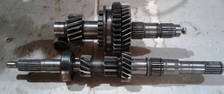 To install 2nd gear only, leaving out the
unused gears.
To install 2nd gear only, leaving out the
unused gears.
Motor drives the front shaft at the left end.
Gear at rear left ("center shaft") drives the differential.
Ratio ends up as about 7 to 1 reduction.
Use Automatic Transmission as a Transfer Case? - Assessment
Even so, the Sprint had been an automatic, and the manual
transmission
would need some mountings welded on to make it fit. Was it possible
that the automatic transmission that came out of the car could also be
configured with a single speed reduction? If so it would be the simpler
one to
use. I had another look at it to try and figure it all out. Turning the
shaft gave the 4 to 1 reduction of the final gear set to the
differential. If I put one gear back, the center of a hidden planetary,
turning that gave about 8-2/3 to 1 ratio, and it still seemed to turn
pretty freely. Adding the planetary that went to that gave about 10-1/2
to 1, but the friction seemed to go up considerably. The 8-2/3
reduction seemed to be the best one, but the 7 to 1 of the manual
tranny seemed like a better ratio for the power of the Curtis motor.
Also there was a missing circular plate with a bearing
holder at the
center for
the automatic, that I probably threw out long ago. (Me, threw something
out?!? Gasp! and, Curses!) But it's a circle,
so I could probably make up a plastic one on the lathe. (In fact later
I
found a 7/8" thick UHMW turned circle that was close enough by putting
in a fat
gasket around the outside to seal the crack.)
On the 24th I returned to the chase. A new idea, really a
synthesis
of old ones, occurred to me. With a fixed ratio transmission, from 5
KmPH to 10, the motor RPM doubles. From 10 to 20 it doubles again, and
from 20 to 40 and again from 40 to 80. Electric motors can run at a
much wider range of RPM.s than gas engines, but the limits show up in a
highway car. 7/8 of the RPM increase (ignoring under 5 KmPH) is under
40. If it wasn't for that little bit at the lowest end, where the RPM
is almost zero and the most torque is needed, a single speed reduction
could be, for example, 3 or 4 to 1 instead of 8 or 10 to 1, and lots of
motors can handle 3000-5000 RPM. 10000 in a larger motor has huge
centrifugal forces trying to rip the rotor apart. So, in
order to use such low ratios, what about slipping the drive in with a
differential ratio until the vehicle is moving at some speed where that
ratio works okay, perhaps 5 to 20 KmPH? Beyond the slip/clutch range
it's a single speed, but with a lower reduction that lets it attain any
reasonable highway speed without over-revving the motor.
It seemed the automatic transmission could easily be
turned into a
fixed 3.9 to 1 ratio transfer case with most of the gears removed.
Again, extend the motor shaft a few inches so the motor
wasn't directly 'plugged in' to the tranny and some shaft is exposed.
Remove the drive shaft to the right wheel and put a short shaft in that
end of the differential.
Next, put mating pulleys on the motor shaft and on the short shaft. If
the pulleys are engaged, and if they are 3.9 to 1 reduction as is the
transfer case, then all will turn in unison. But if a clutch pedal or
lever is engaged and the belt is loose and slips, the wheel will remain
stationary while the short shaft and its pulley will turn twice as fast
as the transfer case is driving the center of the differential. Letting
out the clutch puts more and more pressure on the belt, slowing it down
and starting the vehicle into motion.
The difference between this and what I originally had (by
September 2012) is
that there the slipping friction of the rope/belt was adding nothing to
the propulsion and so it worked slowly and got hot, whereas in the new
one it's
slipping toward making it go and should be in use only for a brief
moment - with great low speed acceleration.
Another way of doing it might be to use a chain drive and
instead
slip one of the sprockets on its shaft with some sort of clutch
arrangement. The original clutch from
the Swift, both halves of which were attached to the Curtis motor
didn't look workable. Beyond top speed considerations, it would be very
interesting to
compare the driving
range with the Swift, using the same batteries and motor but with a
hopefully more efficient delivery of power to the wheels - or I should
say, to one wheel.
It would be possible be to have a different ratio chain or
belt drive
than the transfer case ratio. Even if no clutch or variable part was
made to work, one could have any desired fixed ratio without going
inside the transmission. As detailed in previous issues if it was 2 to
1 while the transfer case was 4 to 1, both would spin freely and the
vehicle wouldn't move. And if it was less than 2, the car would go
backward. If it was around 3 to 1, then by the differential ratios the
final drive would be around 6 to 1. Or it could be made 3 or 5 to
1 or whatever was the best ratio for the highway - or the best
compromise single higher ratio if the clutch idea doesn't go well. If 7
to 1
from fixed 2nd gear gave recommended speeds up to 80 Km/Hr, then
perhaps
6 to 1 (gear "2-1/2") would be good enough for starting and it would
allow up to
95 Km/Hr - a better highway speed. 5 or 4 to 1 with the clutch system
for start-up torque would be even better. Of course, it would be a lot
easier to experiment variations if the whole motor and transmission
weren't
going to be covered up by other components under the hood, laborious to
remove. Perhaps things can be arranged differently than they were?
On the 28th I continued by
removing one rubber boot from a spare drive shaft. (I had bought two at
an auto wrecker along with the manual transmission.) It looked like the
"drumstick" on the wheel end would also fit into the end of the
differential if its threaded end was cut off, and it also looked just
about right to be a hub to weld the 40 tooth #40 chain sprocket to.
(But spacing of mountings dictated I use the original transmission end
with a piece of the shaft.)
I also did some reassembly of the transmission, less over
10 Kg (~23 pounds) of parts - 5.5 Kg of spinning pieces from inside and
almost 5 Kg of other things inside or attached outside. The remainder
weighed around 62 pounds, so that was a significant weight reduction.
And there was still a "one-way catch", a set of plates, that I could
have removed by completing the disassembly, but I couldn't seem to get
the other two gears off and as the plate unit isn't connected now and
doesn't turn, it wouldn't have gained much to do so. (Funny, I remember
the transmission being about 130 pounds when I first removed it from
the car, and I was marveling that it was actually heavier than the
engine that drove it. That would have been with the fluid 'torque
converter' attached - and the oil is now drained. Still it don't seem
to add up.)
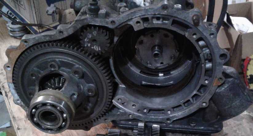 The Right (motor) side of the transmission,
showing the new (short) input shaft,
The Right (motor) side of the transmission,
showing the new (short) input shaft,
and the gear on the middle shaft driving the center of the differential
at 3.9 to 1 reduction ratio (20 teeth to 78).
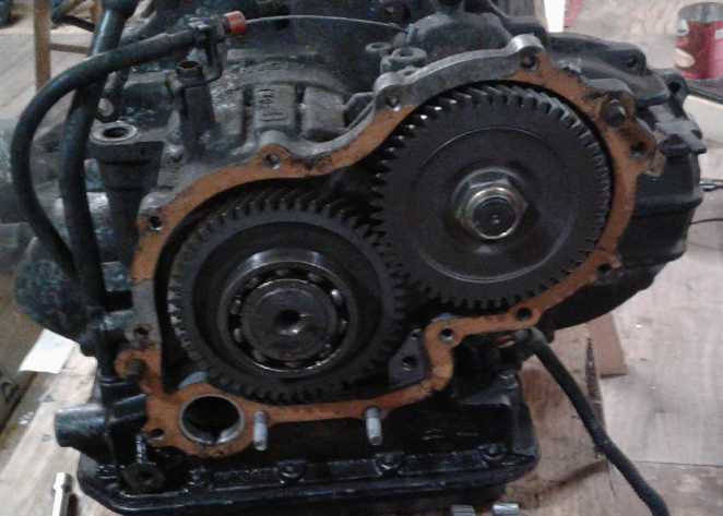 The left side, with the two gears simply
transferring the input shaft rotation to
The left side, with the two gears simply
transferring the input shaft rotation to
the center shaft. (With an electric motor, the reversal of direction is
meaningless.
I can't help but think this seems like an almost total waste of
everything and
it
would be a smaller, simpler and lighter transfer case without it.
...It does set the input and output shafts farther apart.)
To the 62 pounds will be added maybe 10-20 pounds of chain
drive stuff to get the desired results. Seemingly low friction and well
under 100 pounds? Wow! I should have been using the original
transmission as a 4 to 1 reduction transfer case all along! But owing
to prejudice against 40% inefficient automatic transmissions, I failed
to realize it might have some valuable components and (as it wasn't
easy) I didn't disassemble it far enough to find out until this summer.
By October 1st I had the transmission back together
(lots of cleaning, scraping and making of convoluted gaskets), but I
was still wondering just how to connect the novel parts. One problem is
that the shafts from the differential are quite close to the firewall,
so it's hard to put in the sort of large pulleys or sprockets that
would turn with less force. Another problem with the same effect is
that the shafts are too close together to set two larger disks in line.
Adding a third, intermediate shaft with more pulleys might give some
breathing room. Oh, no - it's starting to get complicated again! Which
brings up a third problem: there isn't enough width from left to right
under the hood to add much of any shaft length with the longer Curtis
motor. (It would work with an Electric Hubcap "pancake" motor, but
that's not what will be used.)
Well, whatever the configuration, all the shafts were
going to have to be very secure so they would stay perfectly in line.
As I found out a year ago, the tolerance for error in chain alignment
seems to be very fine. And that is the third problem, which I've
struggled with all along - how to securely hold the moving parts. There
seems to be more design, and certainly more metal, in the case than in
the gears and other components that the case holds, and all the added
parts somehow have to be affixed outside of that.
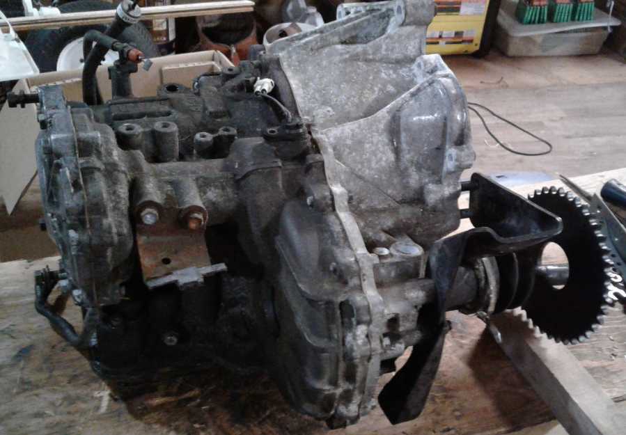 The reassembled transmission.
The chopped right hand CV drive shaft is shown with a 40 tooth #40
chain sprocket on it.
Now... how to attach the loose end with a bearing and securely hold the
shaft straight?
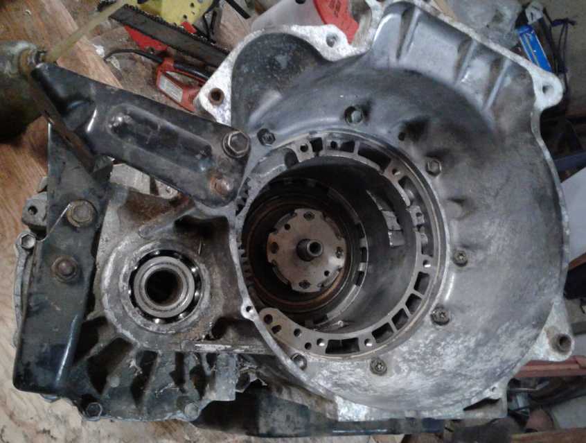 Looking into the reassembled transmission.
The mechanism turns quite freely - if I give the middle piece a spin,
it takes around a second for everything to come to a stop.
Using only the transmission, get two gears
Intruding on next issue for the sake of continuity since I
hadn't posted this one yet, on October 11th I took some of the parts
I'd removed from the automatic transmission and experimented. One of
the parts was a band (spring steel?) that went around a large drum with
a smooth rim. The possibilities for doing some kind of a clutch with
that were intriguing. After all, that was what it was for. OTOH, the
band would clutch the drum to a stop like the one I did with the
slipping rope in 2012. I would rather clutch between two different
rotation speeds, which was what I had later been trying to achieve in a
clutch, expecting greater effectiveness and less heat.
I found that with the drum and the parts further down the
line installed (mainly two planetary gears with their sun gears tied
together), and held the right way, the ratio was about 10 to 1, with
the whole drum assembly turning freely opposite to the shaft. However,
if the drum was held stationary as by the band, the ratio became about
6 to 1. (How does that work? Another ingenious, convoluted mechanical
monstrosity!) I could mount the pieces to stay in this configuration.
The gearshift lever would simply select 10 to 1 or 6 to 1. As it was
pulled back while driving, it would tighten the band and the reduction
would decrease from 10 to 6.
There were some complications. It seemed that I had to
somehow remove the one-way clutch from inside to allow reverse, and jam
certain pieces inside the drum so they couldn't turn relative to it.
The worst part was that it didn't look easy to get into that last
section of the transmission to remove the one-way. (All those three
slipping joins I'd eliminate seemed to have a lot of friction - good to
eliminate them anyway... Hold the presses! It seems these are actually
clutches. I'm not sure how they're pressed, but even a small pressure
locks the two parts together. There are in fact an awful lot of
clutches in there!)
I'd have preferred 4 or 5 to 1 for "high gear" as 6 might
limit top speed again to around 80 KmPH. But I decided that for the
sake of doing something that would probably work because I was only
using components from the original transmission, I would use this
configuration. It would add ten pounds of rotating crud. If it wasn't
as efficient as I might hope, I would live with it for now and maybe
try something else later if I felt inspired. (I won't be installing
that worst inefficiency of automatic transmissions, the fluid "torque
converter".) At this point, I wanted the car to work more than I wanted
to prove the variable transmission system. But it was starting to look
complicated again and I got more convinced that it wouldn't be very
efficient. I started looking again at other ideas.
Electric Caik
Outboard Motor
Outboard - the Throttle don't open?
Trying the Caik outboard motor out again
after I returned from the test trip, I had trouble with the twist grip
'throttle'. One time the motor would hardly turn when turned to "fast",
but later it was fast again. Now I wondered if the twist control was
ever moving the potentiometer to the far end and giving a 'full on'
signal to the motor. Was 60 amps perhaps not full power? On the
16th I went to check it out but I couldn't
figure out how the arm came apart. Not wanting to get far into that, I
dug out a slide potentiometer such as is sometimes used in stereos (the
only suitable one I had - I'd have preferred rotary) and soldered on
the same 3 pin "trailer lights" plug that the twist grip used. I
unplugged the twist grip and plugged in the slide pot.
The motor seemed far more energetic. It spun up to a very
high speed when I'd only moved the bar 1/3 of the way up the shaft. I
went and got the frequency meter and tried again. I found it spinning
up over 3000 RPM (my estimated safe RPM limit) in a flash at under 1/2
'throttle'. I don't know what would have happened if I'd pushed it
farther, but I decided not to find out. Of course in the water it will
have to work much harder to get up to that speed, but it was faster
than the twist grip ever turned it.
Replaced Magnetically Heating Bolts with Plastic Ones
On the 18th I changed those magnetically
overheating metal bolts for nylon ones, without disassembling anything.
The heads of the eighteen #10-24 round head slotted bolts were at the
top of the motor. I unscrewed them, a few at a time, drilled and tapped
the holes for 1/4"-20 bolts, and put in nylon
bolts of that size after cutting them to length. It should make for
lower current and less
heat - however slight the improvement might be. While a change in motor
heating would be hard to measure with
any precision, the RPM.s would be higher for the same currents because
of less drag on the rotor, so if the improvement was significant, it
should be apparent. At least the bolts should stay cool.
Test on the Water
Next another test on the water was in order, on the 19th.
It didn't
go well. I did remember to put the drain plug in this time, and I
brought the RPM (= Hz * 30) meter and a voltmeter for motor
temperature. But I
had taken the new control in the house to keep it out of the rain, and
I forgot to bring it. I had also thought of bringing a DC clamp-on
ampmeter to check the current calibration of the connected one, but
didn't. Its absence was soon sorely felt when the installed one became
intermittent and then just read zero. The motor had trouble starting up
a couple of times, which I attribute to the twist control not going up
very high. (Once I had to turn it to another shaft rotation by hand to
get
it going.) The only reading I got was almost immediately after launch:
about 10 amps
gave 1140 RPM. I hadn't taken one at 10 amps on the previous trip,
so no direct comparisons were possible. I puttered around for quite a
while at about 1650 RPM, which was as high as the control wanted to
take it. I was unable to take any useful measurements except of the
temperature rise inside the motor, and even that not knowing how much
power was causing the rise.
The Overheating Caik Motor
After a while, the motor seemed to get up to about 50
degree temperature rise and stay there for a
while. That was really as hot as I wanted the plastic motor to get. I
turned it down a bit and it cooled a few degrees. I turned it up again
and the motor started getting still hotter; 60 degrees rise or more.
The coil
heat could now be plainly felt on the outside of the composite plastic
case. Just before I got back to the boat launch - and for some time
afterward - I could smell the hot plastic. Did my motors heat up that
badly, and at such low power, probably a little under one horsepower?
This was very discouraging.
But the case above the three coils at the back felt much
warmer than for the
three at
the front. Since they must have all had the same currents flowing in
them, that meant the front ones must be getting better cooling. With
the cover having been off the outboard, I can only attribute this to
the forward motion of the boat wafting air in from the front. That
didn't say much for the magnets acting as a centrifugal cooling fan! On
looking at the picture of the improved rotor (TE News #104), it was
apparent that unlike the Hubcap motors, in the Caik size the inner ends
of the magnets were so close together as to restrict air passage and
perhaps almost eliminate "centrifugal fan" operation. Also I looked
underneath and realized the holes for the circulated air to exit were
pretty tiny.
So the motor probably wasn't making a lot of heat,
it just
wasn't getting cooled effectively so the coils just kept getting
hotter. Somehow the problem needs to be solved or I might as well give
up making what I thought were essentially pretty fine motors. At least
the nylon bolts didn't heat up.
Stiffen Next Motor - Thicker End
Plate, Larger Diameter
Earlier I had noted that the stator end plate had bulged
out from the continuous magnetic pressure attracting the rotor to the
coils, causing the axle to press on the center bearing. I now realized
that the main problem was that the end plate was too thin, less than
1/4". So here's a note for future construction: make it thicker. The
material is light, so even 1/2 or 5/8 inch wouldn't add much weight,
and it would certainly be stiffer.
I would also remark (probably not for the first time) that
the Electric Caik motor would have a lot more breathing room if it was
just a little larger in diameter, with an 8" or even 8.5" rotor instead
of 7.5. The bearing's metal plate would have fit on the inside (as
originally intended) to reinforce the plastic. If I am to make more of
them, I think I would change this. The problem with that will be to get
the new CNC router fitted up and operational to make new molds and
magnet installation jigs. That will take time, so it'll all have to be
put on hold pending completion of more important projects, or finding a
suitable helper.
No Good Coil Cooling Idea
Last month I mentioned
trying (for
new motors) to get cooling air flowing
on the sides above and below the coil wires as well as on their outside
rim. A new idea that occurred to me was to put 2 or 3 narrow slots in
the
windings themselves, using spacers that would be removed after winding
the coils. The 21 turn coils would take three layers to wind instead of
two, but almost every turn of wire would be exposed to cooling air on
one edge or the other. Hmm... come to think of it, there isn't room for
three layers of fat #11 wire in the Electric Caik motor. But it might
work in the
Electric Hubcap size. Oops, such slots would interrupt the magnetic
circuit going through the ilmenite coil coating! Well, scratch that
idea.
Electricity
Generation
VHE/Lambda Ray
Converter
With the trip back to Victoria, trying to figure out how
to surmount internet access problems to post the last newsletter,
oodles
of boxes to unpack and try to figure out where stuff should go in a
house with fewer rooms and less space than my old one, and helping Tom
build the roof over my travel trailer (lifting up sixteen foot long
6"x6" beams and
sheets of 3/4" plywood), over 3 weeks were lost on the converter just
when I had been getting into writing the control software. And with all
my stuff arriving, it was tempting to divert onto another project of
more immediate interest. I did do some tests and work on the Electric
Caik outboard, which had been ready to be tested for almost a year.
Something I unpacked from storage was a printout of a
patent for a
"Motionless
Elecromagnetic Generator" or "MEG" (US 6362718 B1, 2002), which I had
printed off early in my investigations. Now, especially after having
looked into "permanent magnet assisted motors", I can make more sense
of
the diagrams and the idea. This one only claimed to make a few times as
much energy
output as was put into it. Still nothing to sneeze at! It had a
"nanocrystalline" transformerlike core but with the
center bar of the "EI" shape being a permanent magnet with some flux
gaps in the other parts,
the coils oriented oddly around the outside rim, and a simple flip-flop
driving the two coil drivers oppositely. There were two opposite-end
output coils that seemed independent of each other. These were both
rectified, filtered and regulated before driving a load. One had a
sensor circuit for feedback to the oscillator doubtless to change its
frequency
based on the output voltage. If that's all that needs to be done, my
unit should have little trouble! It was so basic and yet it worked,
that I'm starting to believe tapping lambda ray energy is actually
pretty easy... if that's what this unit actually does. It had a lot in
common with the PM assisted motors. The nanocrystalline "transformer"
core material is probably the
tricky bit that has prevented widespread duplication. It's not
something one could readily buy, and it would be really hard to make.
Perhaps
that's why the "status quo police" let this one through?
Another PDF document I reviewed was for a "QEG" ("Quantum
Electric Generator") which had a motor turning a generator, apparently
patented by Tesla in 1896. But the generator had multi thousand turn
coils that made multiple kilovolts as it turned, and some other coils
with 'only' hundreds of turns supplied a 240 volt, 85 amp, 400 Hz AC
output. Surely the energy had to be coming from VHE rays, demonstrating
yet another means for capturing them, this one with moving parts
replacing electronic pulse generation to attain and switch the high
voltages. There was the usual sort of
mumbo-jumbo about the energy coming from the "quantum field",
explaining the device's name.
It seems more and more that getting VHE rays to convert to
a 'visible' electromagnetic energy field requires high voltages, and
perhaps the higher the better. With the 'primaries' and 'secondaries'
of the coils in mine, it just might put out a kilovolt, and I'd better
use at least 1000 to 1 voltage division before feeding it to the
microcontroller for taking readings.
On the 18th I finally got back to the project. I finished
writing the last section of coding, the periodic timer interrupt coding
of the microcontroller. This was the part that put out the pulses and
adjusted them based on the output voltage to keep it within limits.
Writing it was still a ways from having it tested and debugged. I
decided to make a test board with 3 LED.s in place of the coils, and to
slow the clock way, way down so that I could see the LED.s blinking
when the coils should be going on and off. And perhaps something to
simulate the output voltage, driven by (for simplicity) the pulse width
("PWM") of the pulses. That way I could be pretty sure the program was
driving the outputs as expected before trying to run the actual
converter/coils hardware unit.
I had a resistor divider on the microcontroller board to
drop the sensed output voltage to 1/200th for the microcontroller to
read, but it occurred to me that instead of sending the high voltage to
the delicate little circuit board with its delicate human operator, I
should solder the divider into the coils assembly so it was low voltage
coming out of the shielded box.
Safety first! OTOH, the coil drivers are also on the main
board, and they will probably have lethal voltages on them. And it
occurred to me that I should also measure the peak flyback voltages
coming from the coils. They could easily either be too low to be
useful, or high enough to blow the 500 volt transistors. Measuring them
would provide an indication of how long the pulses should be turned on.
Well, I put an extra analog input pin on the sensor connector in case
there was something else to measure!
Of course it would be helpful to know what voltage range
to aim for. This stuff seemed to work best with tubes, which usually
run at pretty high voltages, but if anybody figured out a good voltage
figure for lambda ray conversion, it would seem it never it never got
written down and saved. I'm thinking somewhere over 90 volts or so. But
it could easily be double or triple that or more. Or maybe it's just
proportional to the voltage?
On the 23rd I designed a little test board with an LED for
each coil output, a frequency counter power supply and hookup (For a 5
volt frequency counter board I bought decades ago, a "demo board" from
Intersil.) And I put in an integrator with a couple of capacitors and
resistors whose voltage would rise with the duty cycle of one of the
coil outputs as a sort of Vout simulator. Making it was a struggle. I
had retrieved all my belongings, but much was still in boxes, and they
mostly weren't in settled places yet. Each thing I needed turned into a
big search. First it was the "Fab-In-A-Box" toner transfer paper to
print the board onto. Then for the printer that worked well in the PCB
making process. (I didn't find it until the next day, when I had
already printed it with a crappy printer.) Next was the laminator to
transfer the toner to the PCB. (On the board, the printer's toner had
so many
gaps I filled in the lines with a felt pen. It still came out ugly and
pitted. Well, it was only a testing board. BTW, felt pen works okay
with ferric chloride, but if you use hydrochloric acid and hydrogen
peroxide for etching, it dissolves the felt pen ink. I've never tried
ammonium persulfate etchant.) Finally the hunt was for the "Dremmel"
tool to
drill the holes. I had the board made by the night of the 25th, having
searched through a lot of stuff, much of it more than once. I guess
that's the hazards of moving, with piles of tools and supplies -
clutter everywhere!
I populated the board the next day. I didn't need the
voltage regulator if I ran everything at 5 volts, which was well as I
didn't seem to have any of the one I designed the board for. (Add to
next order!)
Then I learned I would have to take an unplanned trip to
Victoria, and I got no more done.
http://www.TurquoiseEnergy.com
Haida Gwaii, BC Canada