Turquoise
Energy Ltd. News #113
covering
October 2017 (posted November 3rd 2017)
Lawnhill BC Canada
by Craig Carmichael
www.TurquoiseEnergy.com
= www.ElectricCaik.com
= www.ElectricHubcap.com
= www.ElectricWeel.com
Feature: Finally!!!: A Simple,
Practical Plan for an Add-On Wheel Drive Motor! (See: Month in
Brief, Electric Transport)
Month In Brief
(Project Summaries etc.)
Note on Motor Controller Repair/Power Transistor Replacement - Chevy
Sprint Electric Conversion with Improved Transmission? (thought of and
then abandoned... because -->)
- Finally! A practical plan for an add-on wheel drive motor!
In Passing
(Miscellaneous topics, editorial comments & opinionated rants)
- English Alphabet: Like a Number System Without a Zero - British
Columbia Place Names (Where does the cat wipe its feet? Kitimat)
- In Depth
Project Reports -
Electric
Transport - Electric Hubcap Motor Systems
* Chevy Sprint somewhat variable transmission
* Wheel Drive Motor Revived: Hybridize a gas car, the 2001 Toyota Echo
*** The Simplest Plan Ever! ***
* The Unique Feature: Single Variable Pulley on Pivoting Shaft... best
choice?: automatic centrifugal pulley
* Then there's the Slipping Clutch with Flywheel idea(again?)... or a
centrifugal Clutch?
Other "Green"
Electric Equipment Projects
* Plan for a portable "Bandsaw Alaska Mill" for cutting lumber?
Electricity Generation (no reports)
Electricity Storage - Turquoise Battery
Project (NiMn, NiNi, O2-Ni), etc. (no reports)
October in Brief
"Immediate needs" seemed to trump "most valuable overall
projects", and I worked mainly on how to efficiently electrify a car.
Gasoline costs a lot around here, and in my new rural location I find I
am spending hundred of dollars per month on it instead of tens, which I
can ill afford, while electric car components and enough batteries for
two electric cars sit idle in containers and in the shop.
This month I sold the Dodge Caravan minivan (now running
fine) that gave me all the trouble in the move up. I loaned Tom the
pickup truck when he also sold his Caravan. The truck is also for sale
- I figure I can haul pretty much anything it could haul in a trailer
behind the more economical Toyota Echo, which is now all I have to get
around in. I just hope I don't need to level-haul any vehicles behind
such a small car.
Tom is buying a used Nissan Leaf. He still hopes to bring
them up and sell them on Haida Gwaii. He almost had a financial backer
who lives here convinced to bring in five immediately, but the man's
wife (who herself drives the only Nissan Leaf presently on the island!)
vetoed the project.
But I don't want a Leaf now. In October my protracted
efforts to figure out a good way to do an add-on electric drive seem to
have finally, after so many years, paid off. I came up with what looks
like a pretty simple and practical way to put an add-on motor in the
trunk of a car to drive a rear wheel directly. There are even several
variations of the design in case the first doesn't work as well as
hoped, and I have the components for any of them.
For now I'll use the reliable electrical components
salvaged from the Suzuki Swift: the Curtis AC motor and controller and
the lithium ion batteries, and I'll install it all in the trunk of the
Toyota Echo. The efficient mechanical drive to the wheel is the new and
key thing. It will be interesting to compare the performance with the
Swift with the very same electric drive system but without the
reputedly lossy regular automotive transmission, to see how much extra
speed and range it gets. If it draws 80-90 amps in highway cruising
instead of 100-120, and gets 50 Km range instead of 35 with 50% battery
reserve, it will definitely have achieved what is hoped. In fact,
considering the Echo still having its gas engine and transmission will
be substantially heavier than the Swift, achieving even the same
performance would have to be counted as a significant improvement.
Later I may try my own motors and controllers again. And
ideally get the nickel-air batteries going. Potentially, producing
complete economical "add-on hybridizing" kits, or even doing complete
hybridizing jobs, has a lot of appeal. with others to do the actual
work, of course.
Even now, when I want to do most anything, I find that I
usually can't find all the parts that I want. Probably they're there in
a box somewhere. somewhere. A whole slate of mechanical parts seemed to
have vanished until most of them turned up all in one inconspicuous,
unlabelled square plastic bucket when I finally took its lid off. The
rest were in an odd shaped box I had found one large item in and then
forgotten about.
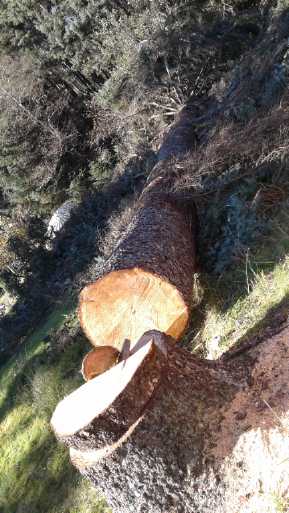 But it's been
difficult to find time for even the most exciting electric transport
and green energy projects. I've spent more time chopping up spruce
branches, and now the fourth huge spruce tree has been cut down and is
lying on the lawn.
But it's been
difficult to find time for even the most exciting electric transport
and green energy projects. I've spent more time chopping up spruce
branches, and now the fourth huge spruce tree has been cut down and is
lying on the lawn.
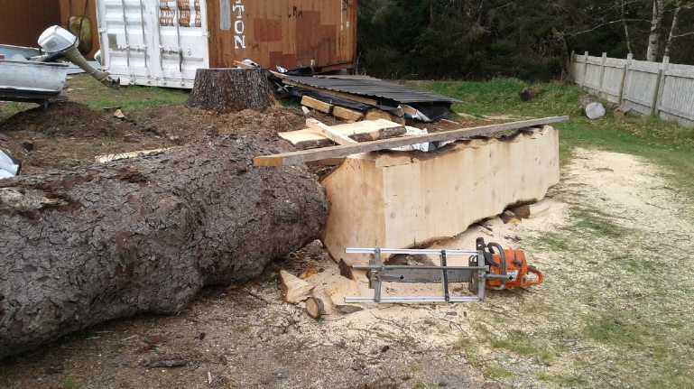 I got a large chainsaw and
borrowed an Alaska mill attachment, and have cut part of another tree
into cants sized for cutting into 2" x 6" and 1" x 6" boards with the
electric sawmill later. There's lots more to go, and now another huge
tree.
I got a large chainsaw and
borrowed an Alaska mill attachment, and have cut part of another tree
into cants sized for cutting into 2" x 6" and 1" x 6" boards with the
electric sawmill later. There's lots more to go, and now another huge
tree.
That's assuming I get my electric mill fixed... and also
that I can't get, borrow or rent some bigger mill. (Say! Why would one
not make a suitable "hand-held" bandsaw that one could use as an Alaska
mill instead of using a noisy, big kerf gas chainsaw? Oh, no, not
another cool project idea! One for the "wish list", I guess!)
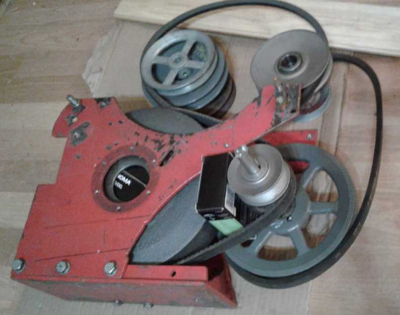
My lab power supply,
finally retrieved from Victoria, soon started to buzz loudly and
malfunction. When I opened the case it worked fine, but when my back
was turned it quit with a burned smell. I spent time on two days fixing
it, replacing a transistor and a quad opamp. It worked great again for
a few hours except it would only put out 2 amps max instead of 10
(charging the box of 7.2 volt Honda hybrid NiMH cells, which by then
badly needed it). Then it went back to buzzing loudly. I turned it off.
(I guess I'll have to charge the rest of the Honda cells with solar
panels in the rain, since 7.2 or 14.4 volts is wrong for any charger I
have.) Perhaps it needs a new main capacitor and I'll order one along
with a gradually accumulated list of other electronic parts I want. If
that doesn't work, I guess I'll need to buy a new one - ugh! (I wonder
what the Coast Guard electronics shop did with the two I designed and
made for them in 1978? I heard a few years later they were still using
them. I still have the schematics, but I can't see spending the time to
make another one.)
 The grand
structure that we (mostly Tom Sawyer) erected over the summer to cover
my travel trailer also progressed. The metal roofing finally arrived on
the 24th and we finally had it covered by the evening of the 27th. Drip
caps at the edges and gutters and downspouts are yet to go. The Sawyers
have moved to Skidegate Landing "for the winter" but I suspect probably
won't be back to turn it into a dwelling per the original plan -
Lawnhill isn't a very convenient location for them as things are
working out. If not, what will it be? A lumber shed? An electric car
conversion shop? A garage/hanger for a ground effect vehicle?
The grand
structure that we (mostly Tom Sawyer) erected over the summer to cover
my travel trailer also progressed. The metal roofing finally arrived on
the 24th and we finally had it covered by the evening of the 27th. Drip
caps at the edges and gutters and downspouts are yet to go. The Sawyers
have moved to Skidegate Landing "for the winter" but I suspect probably
won't be back to turn it into a dwelling per the original plan -
Lawnhill isn't a very convenient location for them as things are
working out. If not, what will it be? A lumber shed? An electric car
conversion shop? A garage/hanger for a ground effect vehicle?
Then, somewhere my last
year's personal income tax (almost finished just before the
move) has disappeared and will have to be redone, and so have most of
my corporate tax and SR & ED papers, which were not in a box titled
"SR & ED 2016" when I finally opened it to do the paperwork. It's
going to be a royal pain doing the SR & ED application for 2016
without a previous year's version to use as a template, and I'll be
working on it well into November. Not that it doesn't take weeks
anyway. I'd have sworn I was very careful with all of these vital
papers when I was packing for the move!
Okay, so much for excuses. On to an electronics thought
and finally the one grand project on the list from the very beginning:
putting a motor on a car wheel to turn an ordinary gas car into a
pulg-in hybrid.
Note on Motor Controller Repair/Power Transistor Replacement
When I went to repair the Kelly BLDC motor controller, I
had a terrible time unsoldering the power transistors from the circuit
board - more trouble than I've ever had before unsoldering damaged
components. I may have ruined the controller, which I still haven't
tried to reassemble. Even if it works, I spent far too much time on
what I thought would be a simple job.
A better plan now very belatedly occurs to me. Instead of
trying to unsolder the burned TO-220 package transistors, I could have
used small side cutters and snipped off their pins, right at the base
of the transistor, leaving as much pin sticking up from the circuit
board as possible. Then I would have snipped off the excess pins of the
replacements, tinned them, and soldered them against the pins left in
the circuit board.
Too late for me for this board, but I suggest anyone who
has to unsolder blown TO-220 (etc) power transistors from a multi-layer
board consider it as a potential technique.
Chevy Sprint Electric Conversion with Improved Transmission?
(thought of and then abandoned)
 Ways to
use an existing transmission to run the Sprint in a more
efficient way seemed to blur and become elusive the more closely the
details were examined. So I thought again about trying a "made
from scratch" transmission with belts. The resulting design seemed
reasonable, but I worried there might be too much tension and belts
would slip instead of moving the car.
Ways to
use an existing transmission to run the Sprint in a more
efficient way seemed to blur and become elusive the more closely the
details were examined. So I thought again about trying a "made
from scratch" transmission with belts. The resulting design seemed
reasonable, but I worried there might be too much tension and belts
would slip instead of moving the car.
Suddenly it was all eclipsed by a
better design for an add-on wheel drive motor that looked very
workable, practical and efficient.
Finally!: A Simple, Practical Add-On
Wheel Drive
After all the frustrations with considering the Sprint
transmissions and their elusive possibilities I had a new thought: a
simpler
way to electrify a car or to turn a gas car into a hybrid. It has an
excellent chance of being successful and practical, and it has a small
number of
pulleys
and shafts to introduce few inefficiencies. The Toyota Echo
looked like my best candidate. The plan would be:
1. Put a very large chain sprocket onto the outside of a vehicle rear
wheel
- preferably the right side as before. It will hardly stick out past
the car body, if at all. The bigger the sprocket is, the less tension
there is on the chain to move the car, and the larger the reduction
ratio that can be attained in a single step. I recently ordered a 120
tooth #40 chain sprocket for
the Miles truck from rebelgears.com, but decided to use it for this
instead. (It arrived on the 28th. I could
do the truck this way instead of the car? - or later, in addition to
the car?)
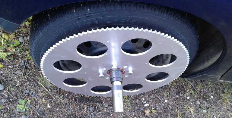
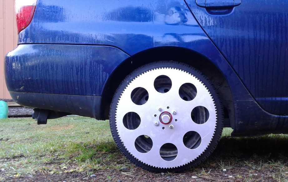 Giant 120 tooth, #40 chain sprocket on car
wheel.
Giant 120 tooth, #40 chain sprocket on car
wheel.
(Just say "NO!" to any rear-right flat tires! - ouch!)
3. Put the motor in the trunk, above the mid shaft, with a
pulley
on it, directly in line with a pulley to be installed on the mid shaft.
A slot is cut into the trunk
floor for the belt to go down through. The size and type of belt
pulleys depends on the linking method, next.
4. Here are three ways to link the motor to the mid shaft in such a way
as to have a lower reduction ratio for high speed driving (estimating
about 6:1 for the Echo with 14" wheels), while still getting enough
torque to start the car moving:
(a) Connect a 4.5" V-belt pulley on the motor in the
trunk to a spring loaded variable pulley on the mid shaft underneath it
with a V-belt. With the variable pulley relaxed at 4.6" effective
diameter, the 10 to 1 reduction of the chain will apply during startup
and lower speed travel. When the pulley is tensioned for higher speed
travel to 2.6" (by the driver pulling a shift lever back), the
increased speed of the mid shaft will provide an overall reduction of
6.25:1, so the motor doesn't have to go too fast to move the car fast.
A late thought (Nov. 1): A custom variable pulley on the
motor could be centrifugally operated, and thus the car would be fully
automatic. It would would relax to the open, minimum diameter position.
A spring between the motor and the mid shaft mountings would tension
the belt. As the motor speeded up, weighted arms spinning on the shaft
would press the outer end of the pulley inward against this spring
tension, increasing its operating diameter and thus reducing the speed
reduction, eg from 10:1 down to 6:1. I think this would be the best
system, but I'll have to make the centrifugal pulley.
 Final(?) version of variable pulley system -
Centrifugal variable pulley to be made.
Final(?) version of variable pulley system -
Centrifugal variable pulley to be made.
Visualize the motor and its variable pulley being above the mid shaft
(in the trunk) instead of to its right.
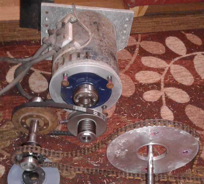
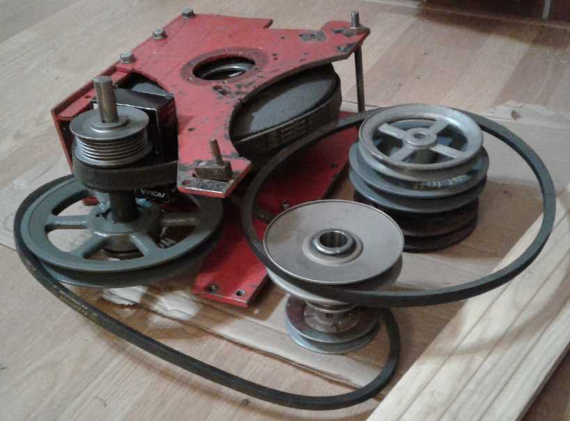
Mid shaft (left), 1" shaft 9" long with 20 tooth sprocket (6:1) and 5"
V-belt pulley, needle bearings.
Standing in for the chain and the giant wheel sprocket, some chain and
a disk (right).
Standing in for the (unmade) centrifugal variable pulley, a variable
pulley with spring (central).
Standing in for the motor... weighing in at 85 pounds... is the Curtis
96 volt motor.
(with fitting still to be removed from shaft where pulley is to go.)
(I must remark there's not much shaft on the motor to attach to. They
could have made it an inch longer, at least!)
(b) In this method the link is a slipping belt
clutch, with a flywheel on the motor. In this case, the lower desired
reduction ratio desired for higher speed driving is used, eg, a 20
tooth chain sprocket drives the 120 tooth one for 6:1. The belt could
be a V-belt or flat belt. To start the car moving, the motor is revved
up with the driver pressing a clutch pedal. As the clutch is engaged
(releasing the pedal), the flywheel on the motor slows. Its stored
kinetic energy combined with the torque of the motor boosts the car
into motion in spite of an insufficient reduction ratio for the motor
torque alone. (To be honest I had forgotten about this technique. I
re-discovered it in TE News #98 when I started looking through to
review what projects I had undertaken in 2016 for the SR & ED
application. So I've already demonstrated experimentally that it
works.) The 10 or 12 pound cast 12" V-belt pulley is probably about the
minimum desirable flywheel, and it could be the V-belt pulley on the
motor if used with an appropriate sized other pulley and chain drive
sprocket to get the right ratio.
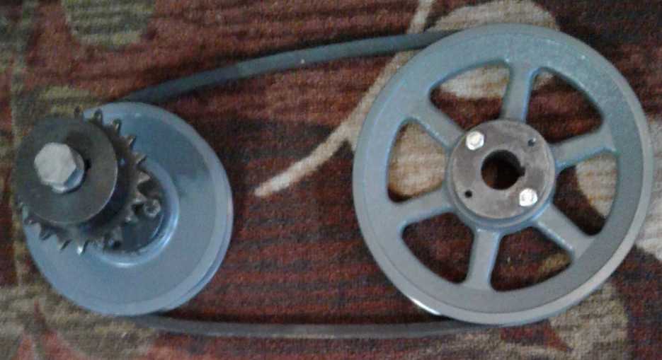 With V-Belt, slipped as a clutch
 or Flat Belt
(c) Use a centrifugal clutch to drive the chain,
again with a flywheel (on the motor or on the mid shaft). Where the
other two methods require operator control - and the controls and
linkages that make them controllable, this one is automatic and makes
the link between the motor and the mid shaft fixed instead of having to
be adjustable while driving. This simplifies the design (as does the
newest idea for a centrifugal variable pulley).
As I seem to already have an "ideal" centrifugal clutch
for the job (www.HilliardExtremeDuty.com, purchased at Princess Auto,
with a 10 tooth #40 chain sprocket output), I was favoring trying out
this last and simpler method first. With this 10 tooth sprocket driving
the 120 tooth the reduction is 12:1. Since 6:1 is desired, and a
flywheel, the motor would get the heavy 12" cast double V-belt pulley,
and the mid shaft a 6" one to double the speed. This double speed of
the mid shaft happens to be desirable as the higher RPM would engage
the centrifugal clutch better, with half the torque required at the
clutch owing to the 12:1 chain drive ratio.
There is however one potential problem with this design,
and it depends on the characteristics of the clutch. If the drop out
RPM isn't much lower than the engagement RPM, the flywheel will be
disengaged too soon and can't impart much of its energy to car motion.
So if I did try this technique, I'd just have to see how it works with
the clutch I have. If it's not satisfactory, I don't think I'll try
making another centrifugal clutch, so I'll have to try one of the other
methods. (The centrifugal variable pulley now looks like the best to me
as of newsletter time.)
 With Centrifugal Clutch
The wheel can move owing to
its suspension, moving the mid shaft back and forth a bit since they
are fixed together in distance by a horizontal bar to keep the chain
always at the same length and tension. The mid shaft also moves up and
down, tied to the motor by the shift mechanism used to vary the pulley
distance (for the first two methods). The mid shaft is thus "floating",
but it links the motor
(moves with the car body) flexibly to the chain sprocket on the
bouncing, vibrating wheel.
The pulley shift or clutch engagement mechanism will have to be quite
strong, as the torque of the
wheel drive will be pushing the mid shaft down - or up when driving in
reverse. An advantage to the centrifugal clutch is that the drive belt
is a fixed length/tension adjustment, so the mountings will
intrinsically be more robust.
By the 24th I finally realized that the mid shaft mounting
and the motor mounting should ideally be all one unit (no matter how
big a hole, or how many small holes, need to be made in the floor of
the trunk). Both ends of the mid shaft mounting, inner and outer,
should be equally tied to the car frame/body to hold it horizontal, and
to the motor mounting to hold that in line. But it needs to move a bit
as the wheel springs, and vibration from the wheel and motor should be
dampened so they don't transmit to the car body. I can think of several
ways to accomplish these things. If the belt needs to move to tighten
and loosen (variable pulley & slipping belt designs), the motor
could be mounted to pivot against this frame to move its pulley up and
down - which suggests relatively simple ways to create the clutch or
variable pulley shift mechanism.
Final notes: a chain in air isn't ideal since chains need
lubrication. One could of
course try a toothed belt or a flat belt that needs no lubrication. But
the chain and chain sprockets is the easy type to find and install. My
thought for keeping the chain lubricated is to have a small reservoir
of oil somewhere with a wick sticking out and brushing against the
chain. I think if it's set up right, it should always keep a bit of oil
coming when the chain is turning, without having it continue running
out oil when the vehicle is stopped.
It can't be denied the having the motor (and motor
controller) in the trunk uses up trunk space. But the biggest space hog
of an electric motor system is the batteries. The Echo has a large
trunk and I plan to put everything - the
charger(s) and the battery box as well as the motor and controller - in
it, so everything to do
with the add-on drive is there except the operator controls (hopefully
none) and meters. It can all have a removable cover over the top to
leave a shallow trunk space above. And I can
always put the back seat down for more room. It's a worthwhile loss of
space that is not often needed!
In Passing
(Miscellaneous topics, editorial comments & opinionated rants)
English Alphabet: Like A Number System Without a Zero
In the English/Roman alphabet, only 5 letters (A,E,I,O,U)
represent vowel sounds. However, there are in fact nine vowel phonemes,
that is, 9 unique single vowel sounds. To make matters worse, the most
basic vowel sound, the basic "grunt" (as the French pronounce the
letter "E"), from which all the other vowels are variants, is missing.
This is like having a number system with no zero. Thus one is forced to
choose some inappropriate vowel. Consider the final vowel sound (for
convenience) in
each of these words:
word
faucet
scissor
puzzle
former
fabulous
future
rider
fashion
merit
alpha
(or, say, the first vowel sound in "consider" or "require", etc.)
It is seen that it is (most commonly) pronounced the same
in each case, regardless of spelling. What has happened is that, with
the required base vowel being missing from the alphabet, any and all
other vowels are employed to spell the word. Let's see... is it closest
to "a", "e", "i", "o" or "u"? Well, really it's none of them. Maybe use
two vowels like "io" or "ou"?... or leave the vowel out completely and
add an "e" to the end of the word? If one
could have one's way just a little bit (fat chance in this case!), I
would make a new letter, perhaps "i" with no dot, to represent the base
vowel
sound. Or maybe the upside-down "e" used in dictionaries. If I really
had my way, there'd be letters for all nine vowels and single
letters for consonants "th" and "sh" (voiced and unvoiced) and the
stopped glide "ng".
Of course, then it might start to look more like Cyrillic,
and we in the west
might not think eastern Europeans and Russians were some sort of
bizarre alien
life forms for the more phonetic alphabets they use.
British Columbia, Canada Place Names
A while back (~1971) one of my high school classmates
brought around a photocopy of the
original sheet of paper describing the new "Murphy's Law" to our
electronics class. There were a number of examples
given, of which I roughly remember just one: "Figures will be given in
the most impractical possible units. For example, a velocity might be
recorded in furlongs per fortnight." The remaining examples may have
been lost to history (at least to my knowledge - or they may still be
out there somewhere), but the basic "law" is remembered to this day,
mostly in electronics and computing design circles: "Anything that can
go wrong will go wrong, and at the worst possible time."
Much later (but still before the internet), someone had a
sheet of "Alberta Place Names", wherein Camrose was described as
"Engine Flower" and "Pharmaceutical Cap" meant Medicine Hat. (which is
a plenty strange name as it is, now that I think about it!)
Ever since, I've thought off and on of doing one of BC
places. But I didn't think of more than a couple. At thanksgiving
dinner this year I finally set out and between us my punster brother
Stuart and I came up with a few good alternative names for places in
BC. (Stuart is the one who calls the Cunningham building at the
University
of Victoria the "Clever Pork" building.) Alas, thinking there were
other copies and then deciding not to include it in TE News #112, and
with
the tablet I wrote them down on later deciding to turn itself off in
the middle of some work and restart without remembering my recent
files,
somehow every copy or the only copy got deleted, as an illustration of
Murphy's law.
Here are the ones I can remember, plus some more I added
later. Most of them are towns.
Those marked with an asterisk "*" are features, generally a lake, a
river or a mountain.
Those not hailing from BC may likely expect to "get" few of them. Those
from BC, and
especially the coast and Vancouver Island may "get" ... well, a couple,
anyway. Maybe I'll think of a few more later for another issue.
BC Place Names (Answers below)
Fish Limb (by Stuart, long ago)
Where the cat wipes its feet (from CBC Radio, long ago)
Fish fortress
Tired of eating wild game for dinner
A Royal that's always burning the meat
Naval Victor
Inky Flow
* Arithmetic Offspring Pond
Abbreviated Litigation
Good place for a long walk?
Big Utensils
* Famous name for such a small waterfall
* A flow of yellow metal
* A tall fabricator of primitive missiles
A harbor in inclement weather
Grassy Knoll (Hint - see top of newsletter)
A meritorious town
Witch Hazel
Tons of small nuts, stale or fresh
Space flights are not directed from here
Tarp for a VW Bus
Torch a wasp
Salmon Arm - Kitimat - Castlegar - Sikamous (sp?) - Queen Charlotte -
Nelson
- Black Creek - Matheson Lake - Lytton - Trail - Grand Forks - Niagara
(Creek) Falls - Goldstream - Mount Arrowsmith - Port Clements -
Lawnhill - Merritt - Hazelton or New Hazelton - See previous answer
(Disclaimer: The clue is not an intended slight to the inhabitants of
either town.) - Houston - Vancouver - Burnaby
- Why does it feel like a 50-50 chance when plugging in a polarized 120
VAC plug is more like 1 chance in 50?*
- A watched pot never boils. An unwatched pot boils dry.
* (Applies to North American plugs where one pin is just a tiny bit
wider than the other, so it's hard to tell which is which.)
Newsletters Index/Highlights: http://www.TurquoiseEnergy.com/news/index.html
Construction Manuals and information:
- Electric Hubcap Family Motors - Turquoise Motor Controllers
- Preliminary Ni-Mn, Ni-Ni Battery Making book
Products Catalog
(Will accept BITCOIN digital currency)
...all at: http://www.TurquoiseEnergy.com/
(orders: e-mail craig@saers.com)
The rest of the newsletter is the "detailed reports".
These
are not for general reading, but for anyone who wants to get into
the fine nitty-gritty of a project to glean ideas for how something
might be done, as well as things that might have been tried or thought
of... and often, of how not to do something - why it didn't
work or proved impractical. Sometimes they set out thoughts more or
less as they occur and are the actual organization into writing of
those thoughts. They are something of a diary and are not as
extensively proof-read for literary perfection and consistency before
publication. I hope they add to the body of wisdom for other
researchers and developers to help them find more productive paths and
avoid potential pitfalls.
Electric
Transport
New Chevy Sprint Conversion(?)
New Plan for All Belts Variable Transmission
My later thought trend (by October 12th) has been that
electric motors are more flexible as to RPM ranges than gas, and don't
really need the sophisticated differential variable transmission. It's
nice that I conceived it, and it would be great for petroleum based
cars and perhaps has other valuable uses, but electric cars can use
something simpler. They really still are best with two gear ranges, eg,
around 10 to 1 reduction for starting up, and 5 to 1 for high speed
travel depending on the motor, wheels and vehicle. Variable between
those ranges is even better. A single variable pulley can provide that
2 to 1 difference of reductions.
After running through the manual and automatic Sprint
transmissions and being unsatisified with the possibilities for making
any sort of really satisfactory unit, I went back to thinking about a
"transmission from scratch" again, this one with belts.
I think
much of
my problem with belts slipping in tests a year or so ago was because
the pulleys I was using had a glossy smooth enamel finish, and that I'd
have got better results if I had taken some sandpaper to them. Now
someone at the auto parts store sold me some "tack" spray, and said
that would fix any slipping belts. If I'd known about that stuff when I
was trying belts before, it just might have made a lot of difference.
And I still haven't given the flat or poly-V belts idea a
fair trial.
So why wouldn't I give it one more try?: redo my own
transmission box
and have just belts and pulleys, including one variable pulley to get
the variable ratios between about 10 to 1 and 5 to 1? At least with my
own chassis
made of flat plate metal, I can attach things and configure things to
my heart's desire as required to fit everything - preferably starting
with a plan with all details worked out in the first place so if all
goes well I'd only have to do it once. With all belts there'd be no
use for oil immersion and I'd just enclose it to keep dust out. (Grease
the bearings well!)
To help me lay things out, I could
make plates of thin plywood and cut holes as required. It would be
easy to do and strong enough to hold the shafts in place and let me put
belts on them (loosely) and see how it turned, of course by hand with
no load. If something didn't fit right, or if the assembly didn't fit
properly into the car, I could easily drill more holes, add
wood to cover holes, or start over with the desired changes. Once
everything seemed to fit together and was in line and turned as
expected, I could replace the plywood with metal plates and bearing
holders.
I would take the 10" drum and mount it on the differential
as a flat
pulley, and the two 2.5" poly-V pulleys and put them on a fixed shaft,
so the two poly-V belts in parallel can provide a final 4 to 1
reduction, hopefully with sufficient traction and strength. (That 99%
efficiency figure for flat belts greatly appeals.)
The motor would simply drive a small V-belt pulley. There
would be
two intermediate V-belt axles, one of which would be mobile to shift
the variable pulley, and the other a further fixed reduction. The last
V-belt would drive the axle with the poly-V belts to the differential.
The need for two intermediate shafts instead of one is a bit vexing:
The shaft with the variable pulley has to pivot on an axis parallel to
another shaft so its fixed pulley always stays at the same distance to
that shaft, to keep the belt tight. Neither the motor shaft nor the
differential shaft is accessible to put bearings on, which would hold a
two stiff
arms assembly to the pivoting shaft for that purpose.
 Two views of the planned transmission.
It would need much larger plate metal sides to hold the extra shafts.
Motor would be at top left pulley in 2nd image
Caveats - Force on Belts?
Because all the belts and pulleys except the last drum
will be
running at least 4 times faster than the wheels, they will have 1/4 or
less as much torque on them and so less chance they'll slip. Both drive
shafts would be connected to the front wheels. If any of the belts
(except the one on the variable pulley) tended to slip or to overheat,
and it couldn't be fixed, that one could be replaced by a chain, which
would need an oil drip or something for lubrication. Hopefully that
won't happen, but it is my main and serious concern as a possible
failing of the
design. I can use decent sized pulleys at the motor.
The 10"
(textured surface) drum with two 'flat' (really poly-V) belts on the
differential should have a pretty good grip, but it has a lot of force
on it. I could wish for a larger drum, but it would be hard or
impossible to fit it into the space available. Either it would hit the
firewall or the drive shafts would have to be moved out and operate at
a substantially greater angle from 'straight' than originally. And then
also the only 'flat' belts I have would be too short.
I could also wish for a larger diameter variable pulley,
but I
don't know
where I would get one or if it's possible make them larger for regular
V belts and still get 2 to 1 speed variation. I had bought a special
variable pulley belt with one near-vertical side and one angled, which
should allow larger variable pulleys, but a fairly
exhaustive search of my shop etc, still cluttered with half full
packing boxes, hadn't uncovered it. (I finally found the box of belts
and pulleys near the end of the month.) And I don't have that larger
pulley (or any pulley) for
it anyway.
Using the Auto Transmission Unit as a 4:1 Transfer Case with Clutch?
Following thoughts of slipping belts for a wheel drive motor system
(below), I did think of a fair possibility for using the Sprint's
automatic transmission unit (Oct. 18th). One of the internal rotating
parts had some sort of clutch that could be engaged by pressing
something against one end. It didn't take much pressure on any one spot
to engage it at least to the extent that it couldn't be turned by hand.
It looked like one spinning part still installed in the case had a ring
that would do the pressing all around the clutch's rim. (An engagement
ring?) Perhaps it is this clutch that slips in forward and engages in
reverse? If it could be connected as required and made to act as a
sensitive input clutch to get the transmission to slip or to grab when
and as desired in either direction, it might be the piece needed to use
the transmission as a 4 to 1 transfer case, with the clutch to get the
car moving from a stop. There are some unknowns in this, like how is
this spinning clutch activated anyway, and can it be controlled from
outside the case? (...or perhaps by centrifugal force?)
IF the mechanism could be coaxed into working as desired,
the most objectionable part would be that 3.9:1 may not be a high
enough reduction ratio, and there's no effective way to alter it if it
isn't. Then again, the Sprint is lightweight and the Curtis motors have
a lot of torque.
But once thought of, the wheel drive idea below looked so
promising
that it quickly became the focus, and all the other ideas were dropped.
Wheel Drive
Motor Revived: Hybridize a gas car, the 2001 Toyota Echo
* The Simplest Plan Ever *
After all the frustrations with considering the Sprint
transmissions and their elusive possibilities, and still being somewhat
leery of the possibility that the belts in the custom Sprint
transmission plan would be too prone to slipping because of the
relatively high torques on them, I had a new thought:
what seemed like a simple and practical
way to electrify a wheel for an electric drive, which could turn a gas
car
into a plug-in hybrid. This was, after all, my original intent in 2008.
It's been a long time coming!
With the
right parts, the numbers give it much less torque on the belts and
hence the best chance of working well. And it has the smallest number
of pulleys
and shafts to introduce the fewest inefficiencies. The Toyota Echo
looked like the best candidate, with the Miles mini cargo van as an
alternate. In fact, as the days passed, I thought of 3 or 4 ways to do
very similar wheel drives in the same basic configuration.
The key component
would be a very large chain sprocket
mounted
on the outside of the car wheel (right rear). The 120 tooth, #40 chain
sprocket that I had already ordered would make for minimum tension on
the
chain
with maximum torque to the wheel. It also would make it possible to
have any reasonable desired speed reduction in a single stage of chain.
Ratio for the other sprocket having (eg): 12 teeth = 10:1 ; 20 teeth =
6:1 ; 24 teeth = 5:1.
Giant 120 tooth, #40 chain sprocket on car
wheel.
(Just say "NO!" to any rear-right flat tires!)
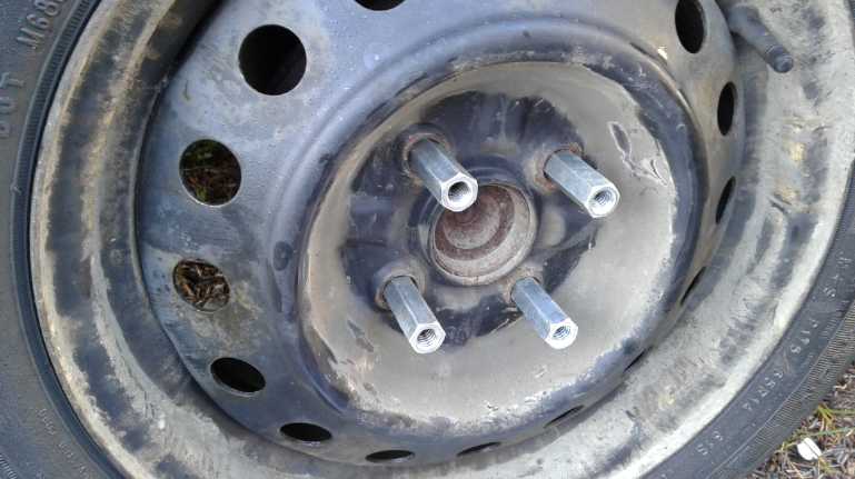 The sprocket is held on the wheel by 7/16"
"coupling nuts".
The sprocket is held on the wheel by 7/16"
"coupling nuts".
One end was tapered, and drilled out and re-threaded (12 mm x 1.5 mm
thread pitch), to fit the wheel.
The outer ends were left as 7/16" with flat ends.
(Yes, I do wish the O.D. was larger!)
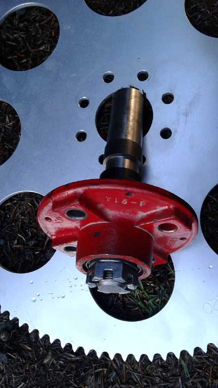 The cut down (on a lathe) trailer hub goes on
the inside,
The cut down (on a lathe) trailer hub goes on
the inside,
with the axle sticking out.
(Four of the mounting holes in the sprocket were superfluous.)
 Another view.
The thickness of the trailer hub, together with the coupling nuts,
set the sprocket almost an ideal distance out from the tire.
The axle sticking out doesn't turn with the wheel.
It will hold the bar that attaches the mid shaft mountings.
(It will be cut much shorter once everything is fitted.)
(Amazingly the nut on the inside end of the axle doesn't quite touch
the wheel.)
The small drive
sprocket would attach per previous issues
(TE
News #91 & 86) where I considered how to mount a motor behind a
wheel and connect it with a chain or belt, except that this sprocket is
mounted on an intermediate shaft, not on the motor shaft itself. (I'll
refer to this as the "MID shaft".)
The motor is in the trunk, behind the wheel and above the
mid shaft. The connection between the motor and the mid shaft is via a
belt and pulleys. This link is the part that differs in the various
options
that I thought of.
In the first way a variable pulley changes the
overall reduction ratio
between around 10:1 and 5:1 or so, with 10:1 being used to start up and
(as
low
as) 5:1 during driving. In the next type, the belt is slipped to act as
a clutch. At the lowest speeds this clutch is slipped to get the
vehicle going, and then the ratio is fixed at 5:1 or whatever. A
flywheel is used on the motor to provide momentum to get
the car to move as the clutch engages, instead of stalling the motor.
In the
last idea, a centrifugal clutch is used instead of slipping the belts,
to provide the same effect.
The basic layout has
various advantages. Any and all the variations can be tried out by
making pretty small changes. And it should be pretty simple to try out
different motors. And we can't forget the maximized efficiency of
having
just one belt and one chain between the motor and the wheel, providing
the furthest driving range for any given battery storage. (Town and
back without recharging, here I come!)
Plus, as noted before, there
are the advantages of any layout in "hybridizing" a gasoline car, over
an electric only vehicle. If the batteries run low on juice one can
start the engine and continue on gasoline. (and perhaps recharge while
driving?) Ditto for any trouble with the electric drive system, which
is especially valuable in a prototype. And of course likewise if one
runs out of gas or has engine trouble, one can drive to a service
station on electric power.
Then, in a typical installation one can use a lesser mass
of batteries, enough for a "typical" drive with a good reserve instead
of going for the
maximum possible range. And one can perhaps use a smaller motor (or a
lower maximum reduction ratio), counting on the gas engine to provide
starting torque in really tough situations with a heavy load on board.
Plus there's the major artificial consideration fabricated
by "the powers that be": one doesn't have to license a second vehicle
at double the cost to drive no further while reducing pollution and
consumption of non-renewable petroleum fuel. (Perhaps this silliness
should be
eliminated by insuring the drivers instead of the vehicles. If I'm
insured for liability, I should be able to drive any licensed vehicle
with my own coverage that I've paid for. And then any licensed and
insured driver could drive a vehicle of mine without worrying about my
coverage and what it covers. Vehicle damage coverage could perhaps
still be on each vehicle, but its cost would be minor compared to
compulsory liability insurance cost. But I haven't thought out all the
possible implications of this idea.)
With a Variable Pulley
This was the first idea (and the last: with a different
variable pulley, centrifugally closed instead of opening against a
spring). The plan would be:
1. Put a large chain sprocket onto the outside of a vehicle rear wheel
- preferably the right side as before. It won't stick out very far. I
recently ordered a 120 tooth #40 chain sprocket for
the Miles truck, but perhaps I'll use it for this instead. (I could
do the truck this way instead of the car. Or perhaps I'll get another
sprocket for the truck later.) This is a key part. The large size
allows a large reduction ratio in a single step. And at about 19"
diameter this sprocket wouldn't fit easily anywhere but directly on a
wheel.
2. Tie a small chain sprocket to a shaft (the "MID shaft") behind the
wheel to connect to
the wheel with a chain. (again see TE News #91 for the mounting plan.)
A 12 tooth sprocket with the
120 tooth one would provide a 10 to 1 speed reduction.
3. Put a variable pulley on the other end of this same shaft, which
should be
underneath the trunk. Because of the speed reduction, 200 foot-pounds
at the wheels (my target torque) would be only 20 foot-pounds at this
shaft, much reducing the chance of the belt being prone to slipping.
(Again the variable pulley I have goes from 4" to 2.5" effective belt
diameter -
pretty small for high torque.)
4. Put the motor in the trunk above the shaft, with a 4" V-belt pulley
on it in line with the variable pulley. A slot is cut into the trunk
floor for the V-belt to go down through. With the variable pulley
relaxed at 4"
effective diameter, the 10 to 1 reduction of the chain will apply. When
the pulley is tensioned for higher speed travel to 2.5", the increased
speed of the mid shaft will provide an overall reduction of 6.25 to 1,
so the motor doesn't have to go so fast to move the car fast.
An interesting point is that the wheel can move owing to
its suspension, moving the mid shaft back and forth a bit since they
are fixed together in distance by a horizontal bar to keep the chain
always at the same length and tension. The mid shaft also moves up and
down, tied to the motor by the shift mechanism used to vary the pulley
distance. The mid shaft is thus "floating", but it links the motor
(moves with the car body) flexibly to the drive sprocket on the wheel.
The shift mechanism will have to be quite robust, as the torque of the
wheel drive will be pushing the mid shaft down - or up when driving in
reverse.
Actual construction will await arrival of the 120 tooth
chain sprocket. I could conceivably start on the motor mounting et al
and the mid shaft, but I'd rather start from the wheel, because it's
the part that I can't alter, and work back to be sure the rest fits to
that. Or I could start on the electrical parts - a battery
box for the trunk, and all the wiring and controls. Hmm!
A late thought was that a variable "V" pulley on the motor
could be centrifugally operated, making the operation automatic. (More
below.)
The Unique Feature: Single Variable Pulley on Pivoting Shaft
A perhaps unique feature of most of my more recent
variable
transmission ideas is in using a single variable pulley
on an offset shaft that pivots to change the distance between that
pulley and a fixed pulley, in order to tighten and loosen the belt and
cause the pulley diameter to change.
This is less complicated than systems where the shafts are
fixed, and one pulley must shrink as another expands in order to keep
the belt tension the same. With a spring loaded variable pulley
shifting is simply a matter of pulling on the
shaft to tighten the pulley toward its smaller diameter, or ceasing to
pull to let it spring out to its larger size. It is also more practical
for an EV because electric motors run well over a wide range of RPM.s
and so don't require such a wide range of reductions as gas engines.
Of course available variable
pulleys and belts made
for mopeds or snowmobiles may wear out
faster than is
desirable. But one could make specifically automotive
belts and pulleys that are better than common V-belts. Honda Insight,
for one, has or at one time had a variable pulley transmission system
with metal
link "V belts". A variable pulley is more complex than a fixed ratio,
but still looks pretty simple to implement. And for an EV
even less
than 2 to 1 change in ratios gives the flexibility to make a lot of
difference.
A final thought: On November 1st it occurred to me that
with a custom pulley, the variable pulley could be centrifugally
operated, and thus would be fully automatic. It would be on the motor,
and would relax to the open, minimum diameter position. A spring
between the motor and the mid shaft mountings would tension the belt.
(This eliminates the need for a spring spinning on the output pulley,
which is instead a regular V-belt pulley.) As the motor speeded up,
weighted arms spinning on the shaft would press the outer end of the
pulley inward against the spring tension, increasing its operating
diameter and thus reducing the speed reduction, eg from 10:1 dropping
to 6:1 depending on driving speed and conditions.
There are very small centrifugal variable pulleys on
mo-ped or snowmobile type variable pulley systems with little ball
bearings in them for centrifugal weights, but from what I was shown at
Victoria Motorcycle these wear out in short order. Thus I would start
with a fresh design, of larger diameter, eg, perhaps the same 2.5" to
4.5" size of the mo-ped output pulley, which would be the input motor
pulley, driving a larger fixed pulley, eg, 4", 6", 8" or 10" depending
on ratios. (A flywheel is unnecessary with the variable pulley type.)
(I just might go for designing this pulley in preference
to using the centrifugal clutch, which I had been leaning toward.)
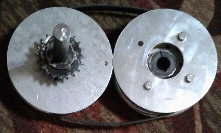
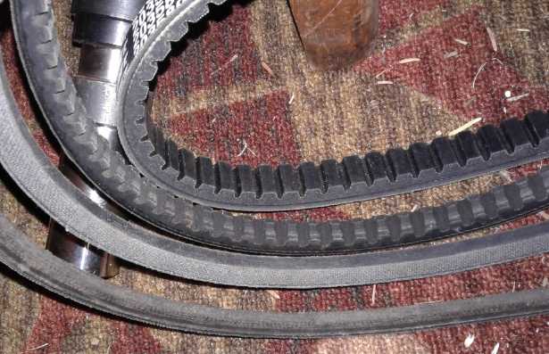 Four V-belts:
1. (rear) The one-side-vertical (actually 87.5 degrees, the other is 18
degrees) variable pulley belt, "Comet" brand.
It is wider than the rest as well as having different angles, and so
won't fit on a regular V-belt pulley.
With the 'vertical' side, its alignment won't shift as the variable
pulley diameter changes.
This is probably the best belt for a heavy load like a car (even with
10:1 speed reduction),
but this one is too short for the larger pulleys which are also wanted
for a heavy load...
and it's the only one I've seen so far.
2. "V" variable pulley belt. They're wider than regular V-belts, but
have the same angles
(13 degrees each side), and those up to about 16 or 16.5 mm wide will
fit regular V-belt pulleys.
The notches in these belts doubtless improve their efficiency for going
around a small pulley.
3, 4. Regular V-belts. These are the most commonly available, but note
the different widths,
over which you seem to have little or no control when purchasing one in
a store.
Then there's the Slipping Clutch Idea [Again? Oct. 14th or 15th]
The variable pulley replaces the idea of having a slipping
clutch of some sort just to get the vehicle moving in order to have a
lower drive ratio for higher speeds.
But I think the clutch idea still has merit, perhaps
especially with a flat belt and pulleys, and especially compared to a
V-belt with a small variable pulley made for mopeds. The one using a
rope in a planetary gear did get the Sprint moving with pretty low
power driving it in fall 2012 (at about 7 to 1 reduction(?) ...egads
was
it really FIVE years ago?) It could be done pretty much the same way as
the variable pulley, so trying out one doesn't preclude the other.
A way to do the above wheel drive might then be to use
chain sprockets to get the desired lower reduction ratio (ie, for
higher speeds), so for example, a 24 tooth sprocket on the mid shaft
with the 120 tooth wheel sprocket for 5 to 1. (...Make that 20 tooth
for 6 to 1, as the Echo has 14 inch wheels where the Sprint has 12"!)
Then use (the previously made) 7" flat belt pulleys on the motor and on
the mid shaft. While the pressure on the belt and pulleys is (almost)
doubled over the variable unit, they are larger pulleys. The 7" flat
pulley compares favorably
with the 2.5" smaller diameter of the variable pulley. Plus, the 99%
efficiency of a flat belt is bound to be higher than that of a V-belt.
However, for the sake of increasing the flexibility and
reducing the number of potential problems getting it going, I'd try it
first with a slipping V-belt. I presently only have one size of 'flat'
belt, while V-belts are commonly available in a wide range of lengths.
Selecting the belt length and adjusting the spacing of the pulleys on
the mid shaft, the motor position can be easily adjusted to its best
position at the right end of the trunk. One can select larger pulleys
than the variable one and a match for it, and I have some very scucum
commercially made cast V-belt pulleys of a good size, eg 5" to 8". The
reduction ratio can also be optimized here by pulley selection without
changing the drive sprocket and chain length.
The clutch mechanism might be (for better mechanical
fitness and to eliminate a heavy spring, at least for the prototype) a
lever that pushes or pulls the pulleys apart to tighten the belt,
rather than a pedal that loosens them. The pull/push down should most
ideally be on the pulley end of the mid shaft or even inboard of the
pulley, partly to somewhat counteract the push down on the outer end
from the torque of the chain tension, which will act as twisting forces
on the mid shaft. Again, all the mountings have to to be strongly built
to withstand the several strong forces that will be acting on them
despite the limited possibilities for attaching them.
Note that it would also be possible to do this arrangement
without a mid shaft, with a belt to be slipped directly between the
wheel and the motor directly behind it. Again the pulley on the wheel
would be as large as possible, and the small one sized for (eg) a 5:1
speed reduction. This arrangement would put the full torque of the
wheel on the belt, so it assumes that the belt can be made not to slip
when it's not supposed to, and also that it can never come off the
wheel when loosened, which it seems to me would be a bigger challenge
than with smaller pulleys. It might be well worth a try at some future
time, but I don't plan to attempt it now.
Or a Centrifugal Clutch
On the 16th yet another idea occurred to me. In a similar
vein to a manual clutch, one could use a centrifugal clutch. This has
the advantages of being easiest to make and being easiest to drive -
automatic. I went to my shop and dug out one of the ready-made
centrifugal clutches that I bought some years back to study or use.
(Where did the other one go? hmm.)
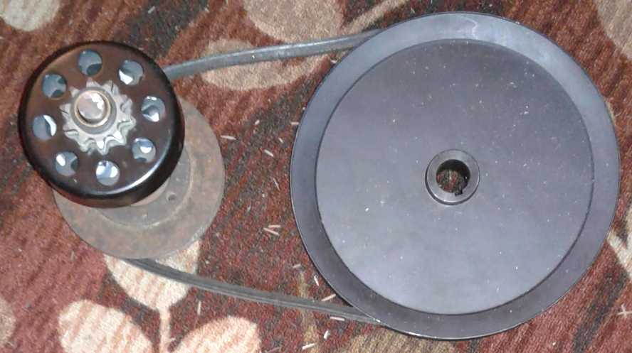
This one had a 10 tooth, #40 chain sprocket as its output.
At first glance, the reduction seemed too high - 12 to 1 with the 120
tooth wheel sprocket. But on further consideration, that would in fact
be pretty much perfect. One of the problems with the stock centrifugal
clutches is that the RPM of activation is higher than is desirable for
an electric motor system. The motor revs up too high in order to engage
the clutch. But the present configuration could run a 2 to 1 speed increase
to the mid shaft, with (eg) 8" and 4" pulleys, so that it spins twice
as fast as the motor. The overall speed reduction to the wheel is then
the desired 6 to 1. Now the shaft spins fast enough to engage the
centrifugal clutch, and the overall reduction is the desired amount. No
mechanism for engaging the clutch is required and the arm linking the
motor and the mid shaft is simpler.
I think I'll try this out first, owing to the simplicity
of construction and installation. At first didn't like the bronze
bushing on the output drum instead of roller bearings. I thought this
would wear out quickly. Then I realized that it only turned until the
clutch engaged. After that it was locked to the shaft rotation.
An interesting point to this one is that the car wheel
turning doesn't couple back to the motor. The centrifugal clutch won't
engage no matter how fast the hub spins, when the input side with the
centrifugal weights isn't turning. So the motor would probably just sit
still while driving on gas. This also reduces the potential for
regenerative braking (which would drop out at low speeds), and it
precludes charging via the motor-as-generator while driving. But that
bronze bushing would really be spinning - ooh!
This plan told me where I might start before the big
sprocket arrives: The clutch is sized for a 3/4" shaft and I didn't
have any. Turning down one end of a 7/8" shaft would be ideal. For that
I had to set up the machine lathe, which hadn't been done since the
move. After locating its motor I accomplished this on the evening of
the 19th (even eliminating a couple of nuisances like a pulley that
used to rub on a guard with a scraping noise).
Next, just how was that floating mid shaft and its two
components to be mounted, anyway, to be tied to the wheel and to the
motor? The bar from the wheel has to be outside the big sprocket, so it
makes sense that it's also outside the small sprocket of the
centrifugal clutch. There's no particular need for the shaft to extend
past the sprocket, except that would be the place for a bearing, and it
will provide an end stop so the clutch drum with the sprocket can't fly
off the end. Then the arm only provides a shaft bearing at the outer
end. It might twist, and there's nothing to keep the shaft and the arm
from sliding away from each other. Keeping the shaft and chain aligned
would seem to suggest the arm from the wheel needs either to fork into
two end points ("y"), or to turn a "U" at the end, with the arms of the
"U" on each end of the mid shaft:
|
|
U.
(Well, that's probably as clear as mud!)
The Chain Sprocket Arrives!
The giant 120 tooth sprocket arrived on the 28th. The
mounting holes lined up with the wheel studs, but I thought it would
take some doing to mount it. Probably I'd have to make wheel nuts that
were a couple of inches long and tapered at both ends, to hold the
wheel on and also to hold the sprocket far enough out that the chain
clears the tire. I've never been able to find much 12mm x 1.5mm
hardware except the exact stud bolts and short tapered nuts that are
usual on cars. I thought the trailer hub would have to be cut (or
drilled) out where the wheel-nut bolts go through the sprocket to hold
it on, as it overlapped with them.
But it turned out to be simpler. I found 7/16" coupling
nuts and on Halloween (31st) - one year to the day since I first landed
on Haida Gwaii - I turned just one end of each conical on the lathe,
and drilled out and re-threaded that end that end for the metric wheel
bolts' size. (The dealer actually pulled the 12mm x 1.5mm tap out of a
full tap & die set and sold it to me separately!) The other end I
left with its original 7/16" thread, for bolts I can easily get around
here, and I left the end flat to butt up against the face of the
sprocket. Then, I put the cut down trailer hub on the inside where
there was just enough room for it, and its thickness, added to the
length of the coupling nuts, set the sprocket away from the tire just
the right amount. Having the hub on the inside meant the axle stuck out
just far enough, to give the lowest possible profile for the bar across
to the mid shaft. Although the trailer hub was 4" diameter (101.6mm) 4
bolt pattern instead of 100mm, with its lug bolts removed its larger
holes accommodated 100mm with little slack using the 7/16" bolts (which
BTW needed to be about 1.75" to 2" long and were purchased that day).
And I had picked 2.5 inches "out of a hat" as the size for the
sprocket's center hole, and that turned out to be just slightly larger
than the flange round the trailer hub center (2.47"), so that too was
pretty close to perfect.
With 2 of the nuts prepared I trial mounted the sprocket
on the car wheel while there was still some light to look and to take a
picture. I could hardly ask for things mostly not made to fit together
to fit together better, except that I wished the rather thin coupling
nuts had a wider outside diameter - more like a regular wheel nut
diameter - to provide more support for the torque from the sprocket to
the wheel. But they'll do for now! Perhaps I can find some better ones
on line later.
Other
"Green"
Electric Equipment Projects
Plan for a
Portable Bandsaw "Alaska Mill" for cutting lumber?
A chainsaw with an Alaska Mill attached can cut logs into
straight pieces of wood. They have a great advantage for the small
operator of being able to cut the log where it lies - no need to
transport a tree trunk that can weigh tons. However, they are noisy and
slow, they use a lot of fuel and they waste a lot of wood in a thick
(3/8") kerf.
To make the first cuts in the rough shaped log, one places
a long flat board such as a 2" x 8" on top, sitting on nails or screws
that have been pounded or screwed into the wood so that the board is
supported on the heads of all of them. (I prefer deck screws, put in
with a cordless drill, because it's easy to twist them up or down until
all are in alignment. A string is helpful.) 2 or 3 longer nails/screws
are put through the board into the log to hold the board in place. The
depth setting of the cut has to be greater than the length of the nails
plus the thickness of the board. The saw, sliding along the board,
makes a horizontal cut through the entire width of the log at height of
the cut. (usually near the top of the log) The mill and chainsaw bar
have to be long enough to fit over the log at that depth. After two
such cuts have been made at 90 degrees (use a square!), the log has two
flat sides to slide the mill along and the board and screws are put
away for the rest of the cuts.
On the evening of the 28th a new idea came to me: to use a
"hand held" bandsaw mill in place of the chainsaw mill. Here is the
basic outline, which is as far as I'm taking it for the present.
Most bandsaws are made with a sort of "C" shaped frame
well out to the side to allow a maximum cutting width. The trick here
is that for the mill, that width becomes the cutting depth, so it
doesn't need to be anything like so wide. The design of the saw then
can be fundamentally changed.
Two straight steel bars (or even just one - "unistrut"?)
run from the left wheel to the right wheel to hold the wheels in place.
This will be inherently a lot more sturdy than the typical "C" shaped
offset bandsaw frame, and it uses minimal material. This will bring the
weight and size of a bandsaw way down. For 14" bandsaw wheels, then,
the maximum possible depth of cut will be 7.5" less the amount of frame
sticking out below. If it's a 2" frame with no other impediments, then
the maximum depth of cut will be 6", which I would consider adequate
for most purposes. 12" wheels with a 4.5" cut depth might be considered
adequate by many, and even 9" wheels (if a wide cutting band will
readily bend to that diameter) could make 3" thick boards. (However,
these small sizes might need to make more than one cut to square off
the top of the log.) A motor sitting on the top of the bars, less than
6" in diameter to fit under the band, would be ideal to keep the weight
centered and low down. If a larger diameter motor is required, it will
have to be mounted to the front or rear with only its pulley in line
with the driver wheel pulley. (Where there is no power I would run a
generator to power the saw motor rather than mount a gasoline engine on
the saw, keeping the noise and exhaust away from the miller. I would
break the log into movable slabs or cants, then do the rest of the
cutting where there's a plug in.)
Below the bar would be a flat "Alaska Mill" type of frame
that can be adjusted up or down to set the depth of the cut. Somewhere
a small jet of water will wet the band to keep it cool. Carefully
situated handholds and safety guards taking potential band breakage as
well as flying chips into consideration would of course be part of the
layout.
It would have a very thin kerf and use much less power
than a chainsaw mill. It will still probably be pretty slow cutting. Is
it worth building? Might an "Alaska Bandsaw Mill" replace most small
"push saw along tracks" sawmills? I have a need for one if I'm going to
sell lumber, but at this point I have no plans for interrupting other
projects to start on this one. For now, I'm going out for my daily (or
less often) dose of trying to start a huge ornery chainsaw, noise from
which hearing protectors are inadequate, and hot gasoline exhaust fumes
spewing in my my face, to get covered with sawdust and do my daily
Alaska mill single cut on one of the big logs lying in my yard,
intending to eventually break them all down until I can move the pieces
and get them under cover. ... ... ... So much for that! I couldn't
start the chainsaw and I'm tired out from trying. My typical results
with pull-rope-to-start gasoline appliances! An electric bandsaw mill
might have finished the cut by now, or at least would be well into it.
I wondered what I might use for a motor for such a
hypothetical saw. Electric induction motors are pretty heavy - my 7.5
HP on the pivoting blade mill is about 50 pounds, and that's a light
one. The chainsaw with mill attached is about 40 pounds. Could a
bandsaw Alaska mill match that, or even be lighter? One could do a gas
motor, I suppose. Then in the shop I saw the Ryobi skill saw with a
broken blade guard. Assuming it would be easier to buy a new saw than a
blade guard, I had planned to cut off the cord and throw it out. Here
was another idea. It said it was 13 amps. In theory that would make it
over 2 horsepower. (13 A * 120 V = 1560 W) High RPM: more power in a
small size with light weight... and it would plug in anywhere. Okay,
that's not much power for a mill, even a bandsaw mill. But in the
"Alaska" mill, the saw can be swiveled back and forth to cut first at
the right, then at the left, then the center. Unlike a mill on a track,
it doesn't have to cut all the way across at once. It would be slower,
but it would probably work! As long as the friction from the section of
blade that isn't cutting at any given time isn't too high.
Someone said he'd seen such a mill on youtube. But his
description sounded odd: stand the log on end and cut down
vertically?!? I found a chainsaw mill that cut down, but no bandsaw
Alaska mills of any sort. The clerk at the chainsaw store, who had done
plenty of Alaska milling himself, had never heard of such a thing. (I
went there because I couldn't start the chainsaw, but it fired on his
first pull!, and started a few pulls later. I figured it would! Somehow
it had been flooded, and leaving it for two days hadn't helped. I've
never heard of such a thing!) I cut my slab the next day, and with my
ears still ringing hours later, I determined I'm going to build that
bandsaw Alaska mill! Or maybe I'll call it a "BC Mill". Diversions,
diversions! Car first. Lambda ray energy second. Then the mill. No, the
ground effect craft! No, the mill! No, SR & ED tax report for
2016!... Hmm.
http://www.TurquoiseEnergy.com
Haida Gwaii, BC Canada