Turquoise
Energy Ltd. News #114
covering
November 2017 (posted December 2nd 2017)
Lawnhill BC Canada
by Craig Carmichael
www.TurquoiseEnergy.com
= www.ElectricCaik.com
= www.ElectricHubcap.com
= www.ElectricWeel.com
Month In Brief
(Project Summaries etc.)
-
Format - Feedback is welcome - Bandsaw Alaska Mill - Hybridizing the
Toyota Echo - Alaska Milling - (note: Palaeos.com URL)
In Passing
(Miscellaneous topics, editorial comments & opinionated rants)
- Arthritis Cure: Borax. Still Working. - "Foambergs" (More Sea
Foam from aerosol spraying?)
- Project Reports
-
Electric
Transport - Electric Hubcap Motor Systems
* An Off-the-Shelf Centrifugal Variable Pulley?
* Back to a centrifugal clutch? - some design considerations
* Double Set Screws: Make sure it won't come loose
Other "Green"
Electric Equipment Projects
* Bandsaw Alaska Mill: Wheels and bands - making plywood wheels
Electricity Generation
* An Attic Windplant? (just an idea)
Electricity Storage - Turquoise Battery
Project (NiMn, NiNi, O2-Ni), etc. (no reports)
November in Brief
Format Change
As I'm not e-mailing the newsletter itself now but only
links to it, I'm going to change the format a little. Month in Brief
will have just very brief descriptions of the projects. The "detailed
reports" will have the meat for those interested.
Feedback?
Occasionally people write me with questions, ideas or
suggestions about my projects written up in these newsletters. Perhaps
others are wondering about
something, or thinking I'm off base and "Yah, good luck with that!" I
wish to say that I appreciate the efforts people take to
write me, and that whether I use an idea or not or whether I agree or
not or take advise or not, I welcome ideas and constructive criticism.
And I love to chat
with those who may reach this little corner of the world and visit and
perhaps look things over. I make all my work public and public domain
via these newsletters, and more thoughts by more people can improve the
focus and perhaps together we may come up with better things than I
sometimes do by going off on a tangent on my own.
Bandsaw Alaska Mill (how about "Carmichael Mill"?)
Near the start of the month, the new "bandsaw alaska mill"
idea went from "wish list" to the top of the list. It shouldn't be too
long before I have a working saw, and it has excellent commercial
possibilities for myself, which most of my ideas don't. So I ordered
parts, and by the end of the month they had arrived and I at least had
a start on making the saw. The first one is to be electric. If it works
as well as I hope, there may be more models coming.
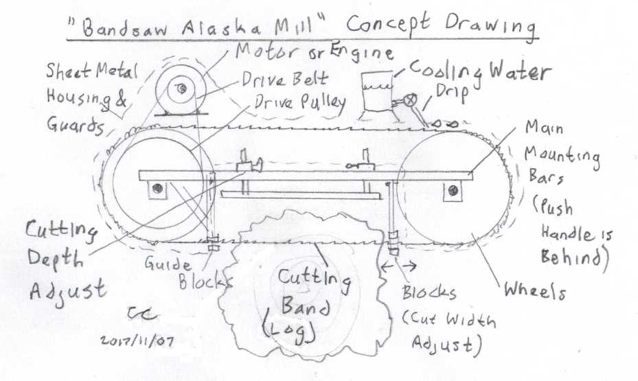
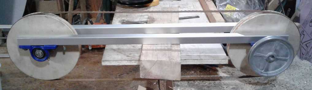 The main frame for the "bandsaw alaska mill",
with 10" x 1.5" plywood wheels
The main frame for the "bandsaw alaska mill",
with 10" x 1.5" plywood wheels
and a 93" x 3/4" cutting band for up to 20" wide, 6" deep cuts.
Hybridizing the Toyota Echo
I continued on the plan for hybridizing the Toyota Echo,
switching the "how to get it moving" technique (of 3 potential
techniques
mentioned last month) to a large centrifugal clutch that I made almost
2 years ago (replacing variable pulley ideas, and a "too small"
commercial centrifugal clutch). I also changed it from a (probably
inadequate) belt drive to a chain drive from the motor to the clutch.
Actual work in November was limited to ordering various needed parts as
the plan changed and matured. Most of them were received by month's end
except for a 28 tooth #40 chain sprocket for the motor.
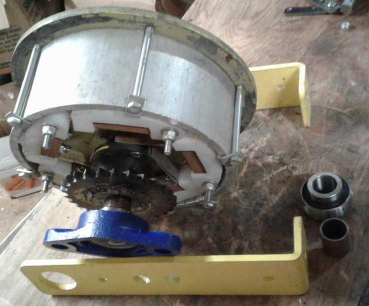
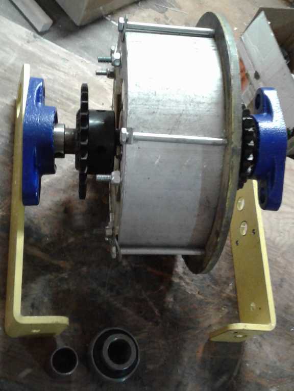 The mid-shaft components sort of assembled.
This goes under the trunk and behind the right rear wheel.
Left is the drive sprocket from the motor in the trunk, through the
centrifugal clutch to the drive sprocket going to the wheel, on the
right.
Alaska Milling
My other perhaps notable activity for the month was
milling up a huge spruce log into "cants" (long pieces of log much
larger than dimensional lumber, eg 6" x 20"). I had started this in
October, but I
didn't finish dicing up the whole log until late November. Of course,
this work is what led to the idea for the "Bandsaw Alaska Mill". Some
of the cants are still virtually too heavy to move, and without a big
forklift or something it would still be a major operation to get them
out of my driveway. When I finish the bandsaw I hope to cut them into
pieces of lumber and carry them off.
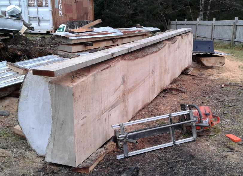 The remainder of the big spruce log, here with
four very wide, 16 foot cuts to go to dice the last section up.
The remainder of the big spruce log, here with
four very wide, 16 foot cuts to go to dice the last section up.
For various reasons they took over a week - including wanting help to
move pieces once they were cut.
At the very least, a bandsaw would have left the bottom piece over an
inch thicker by turning less wood into sawdust.
At best, it would also have made the job faster, easier and more
pleasant,
and left smoother surfaces.
Note: In TE News #100 for my Permian article ("all amphibians -
no reptiles yet"), I referenced a website I labeled in two places as Paleos.com.
Looking
for
it
again
I was for a while distressed - I couldn't find
it. Had
such a fine reference site simply disappeared from the web? Then I
tried a
web search for one of the sentences I quoted. The actual URL is Palaeos.com
(which I had labeled it as in two other places). My apologies to anyone
who was looking for that site and used the wrong URL.
In Passing
(Miscellaneous topics, editorial comments & opinionated rants)
Arthritis Cure: Borax. Still Working.
In TE News #88 I mentioned having found out that arthritis
and calcium buildup in the joints (not to mention osteoporosis) is
caused by boron deficiency, and that little aches and pains in the
joints went away when I started taking borax. Boron deficiency inhibits
proper metabolism of calcium, which is why it ends up in the joints and
gets depleted from the bone.
Well, in case anyone thought that sounded like a silly fad that would
soon be abandoned, I will say that it's still working after 3 years and
that I'm still glad I found out about it!
I seem to have gravitated to a recipe of a teaspoon of
borax in a half litre (half quart) of water, and drinking a teaspoon a
day, or for convenience two teaspoons every second day. One teaspoon
per litre, one teaspoon a day, seemed to be not quite enough, for me.
Other similar recipes and recommendations may be found on the web.
(And don't forget to get some calcium and vitamin D to go
with that. 1000mg of vitamin D per day (or 15-20 minutes of sunshine on
the skin) cuts your risk of cancer literally in half. In fact, as
I get older I find myself taking about 6 supplements a day. That way I
expect to be healthier longer and I won't end up needing prescription
medications with side effects. "An ounce of prevention is better than a
pound of cure", as they say.)
"Foambergs" (More sea foam from aerosol spraying?)
 In some places they have icebergs.
In Hecate Strait and on the east coast of Haida
Gwaii this winter we seem to have "foambergs", bobbing around in
the ocean, washing up on the shores and blowing
around in the wind - even blowing across the highway in storms.
I originally included this picture just because seemed
interesting. I hadn't meant to bring up "chem spraying" again, but as I
think about it, this seems to fit into a bigger picture. I can't say I
remember seeing
anything like it in the Pacific in decades past.
However, in Victoria a couple of years ago it all seemed
to be related to aerosol
spraying, with foam and colored water appearing
even in my fish pool and rainwater barrels, while headlines noted mass
die-offs of sea birds in the ocean: foam soaked birds had lost their
waterproofing and got hypothermia, washing
up on mysteriously foam covered beaches from California to Washington.
It was thought at the time there must
have been some sort of big unreported spill... but in my rain barrels
too? I mentioned it in TE News #88. Mass die-offs
continue daily, worldwide [TE News #101]. They only make local news now.
Among other mentions of "chem spraying" in various issues,
I did a
bigger write-up of how and why aerosol spraying
appears to be altering the wind circulation patterns and hence the
whole climate of the planet in TE News #109.
The rest of the newsletter is "in depth reports"
for
each project. I hope these will help anyone who wants to get
into a simliar project to glean ideas for how something
might be done, as well as things that might have been tried or thought
of... and often, of how not to do something - why it didn't
work or proved impractical. Sometimes they set out inventive thoughts
almost as they occur - and are the actual organization and elaboration
in
writing of
those thoughts. They are thus something of a diary and are not as
extensively proof-read for literary perfection and consistency before
publication. I hope they add to the body of wisdom for other
researchers and developers to help them find more productive paths and
avoid potential pitfalls.
Electric
Transport
Wheel Drive
Motor: Hybridize the 2001 Toyota Echo
* The Simplest Plan Ever *
An Off-the-Shelf Centrifugal Variable Pulley?
After deciding the best setup would be one with a
centrifugal variable pulley on the motor, I went to look for the one I
had off of a mo-ped. When I found it, it seemed to be missing a couple
of pieces - or perhaps just the shaft was attached to the mo-ped and I
couldn't extract it. I looked back in TE News to when I had obtained
the variable pulleys from Victoria Motorcycle, but I found only the
output pulley, and a couple of pulleys attached to centrifugal clutches
(TE News #103). Anyway there was enough to see how it worked. It didn't
look as I remembered it - perhaps I was remembering a different one
that I was shown at the time.
Six small and not very heavy cylinders were the
centrifugal weights. (My memory was of six ball bearings.) When the
shaft was spinning these cylinders pushed out against a flat angled
piece on one side and a curved angled piece on the other. The flat
angled piece would have been fixed on the shaft, so the weights would
have forced one side of the pulley (the other, outer, face of the
curved angled piece), towards the other side of the pulley, increasing
the effective diameter. It seemed like a good way to do it, but it
seemed to me to be too small and light for a car. The thing to do would
be to make something similar but larger and heavier, perhaps with an
effective pulley diameter of 2.5" to 5". This would drive a 5" fixed
pulley, yielding a reduction of between 2 to 1 and 1 to 1. The 6 to 1
chain reduction would then make the total reduction between 12 to 1 and
6 to 1, allowing sufficient torque for getting the car moving and lower
RPM for higher speed driving.
Then I went on line and found there were companies making
larger variable pulleys, up to 100 HP rated. Now we're talking! One of
them, "www.SpeedSelector.com", had a PDF of calculations for using
variable pulley systems. It noted that there were two types, the "fixed
center distance" with inversely matching variable pulleys, and the
"adjustable center distance" where there was just one just as I've been
proposing, and the distance between shafts changes to alter the
effective pulley diameter. (I should have known it already existed!) If
there was a centrifugal type, that would be the way to go, but they
weren't mentioned in the document. The document also stated that the
pulleys were aluminum, which carries off the heat from the belts.
That's good info. But applying the formulas and figures given was a bit
beyond me. I don't suppose there are a lot of models to choose from in
the desired range.
They claimed to have a complete line of pulleys and belts.
I also noticed the flat-one-side variable pulley belt I bought said
"www.HoffcoComet.com" on it, so it should be possible to order belts,
probably just about whatever you want, from there too. Centrifugal
variable pulleys are more in doubt.
On the 6th I went back to SpeedSelector.com . They didn't
have any centrifugal variable pulleys, only spring loaded ones. Their
whole focus seemed to be different - industrial fans and fixed
equipment.
Then I went to
HoffcoComet.com, and found they had fixed axle variable transmissions
not only for 8 horsepower, but also up to even 150 horsepower. They
definitely had transport applications in mind, and were an
"aftermarket" or "OEM" supplier. The drive ratio ranges were better
than I needed, even about 4-1/2 to 1 with a single variable pulley. I
started drooling
over the 40 HP model, with 7 inch pulleys and a big, fat belt. That
sounded like the right sort of size, and they could recommend a bigger
one if they thought it was too small. I looked for the
phone number. That would surely solve all the problems,
however many hundreds of dollars it cost! Let's see, contact info... No
phone, no e-mail, no "contact us" page. What? I did some more searching
and found that Hoffco-Comet had gone out of business in 2009. The site
I was looking at was just a legacy site, and the components Princess
Auto had been selling were just leftovers! I must say I was rather
crushed.
From the
HoffcoComet.com web site:
Model 94C Duster Clutch Series
This is the one to use for all V-twins and
high torque applications!
With a beefy 1-3/16" belt, the 94C has the rugged reliability
needed
when you want to spend your time riding, not making repairs. A 3.49-1
low
and
a .78-1 high provides a wide gear range for great low end
pulling power without sacrificing top speed! Custom calibration of
drive unit is quick and easy allowing you to get maximum performance
out of your engine. Contact Comet Industries for recommendations.
| Comet 94C Series Torque Converter |
|
Specifications
|
Features
|
Applications
|
| Diameter: 7-1/4" |
Simplicity |
Snowmobile |
| 2 Cycle & 4 Cycle |
Fewer Moving Parts |
Odyssey |
| Housing: Stamped / Cast |
Easy Calibration |
Industrial Equipment |
| Bore: 30mm 1:10 Tapered 1" & 1-1/8" |
Performance |
Light Utility |
| HP: up to 40 |
Limited Maintenance |
|
| Engagement: 1600 - 4600 RPM |
|
|
Not available!?! Curses! Could I even find a belt like
that one,
anywhere?
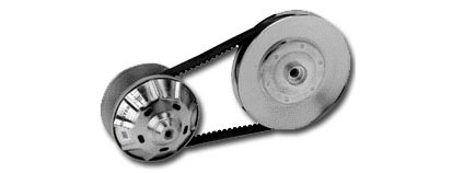
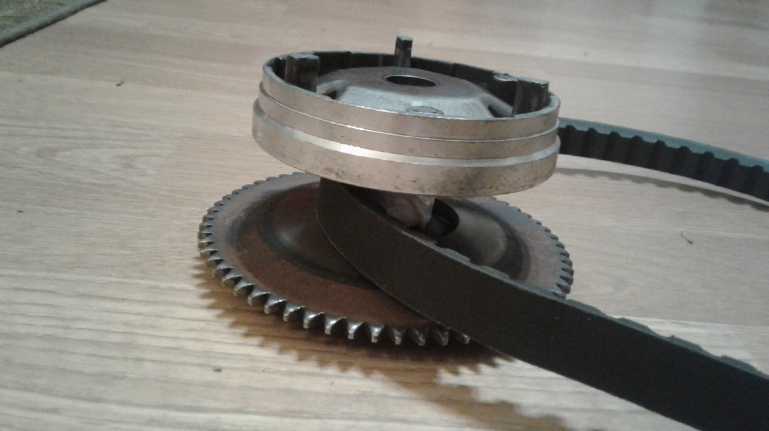
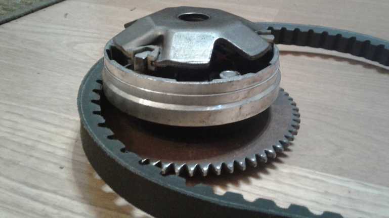
Just for reference here are pictures of the small (moped)
variable pulley that I obtained as scrap.
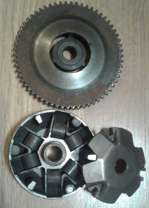 When the pulley spins faster, the cylindrical
weights push outward.
When the pulley spins faster, the cylindrical
weights push outward.
This forces the cast part of the pulley toward the rusty steel fixed
piece,
narrowing the pulley and forcing the belt out to a greater diameter.
 (I'm sure the grooves in the belt improve the
efficiency considerably over a regular V-belt,
(I'm sure the grooves in the belt improve the
efficiency considerably over a regular V-belt,
allowing it to bend around the pulleys more easily. Why don't they make
them all that way?)
A Centrifugal Variable Flat Belt Pulley?
To continue with the variable pulley theme, on the evening
of the 29th I
thought again about my idea for a flat belt variable pulley (TE News
#101, The "Double Barrel Torque Converter?") I still like the
'almost lossless' efficiency aspect to flat belt operation, if the
mechanism can handle the torque without the belt slipping. The part I
was having
conceptual trouble with was how the input "barrel"/flat belt pulley
could be made centrifugal. It seemed like it would need a hopelessly
complex mechanism. Now I see the weight of the "barrel staves"
themselves as being the centrifugal weights for the pulley, and it
suddenly seems more feasible.
And instead of having a reciprocal variable pulley on the
output side (complicated), I would go for a fixed diameter output
pulley with varying center distance: a spring pushing the two pulleys
apart to tension the belt and the centrifugal force pulling them
together at higher speeds.
I think such a mechanism would run pretty
smoothly, but it just might be that the staves with spaces between them
would set up a lot of vibration as the unit spins. One might make them
to "mesh" between vanes like escalator stairs do. That idea might be
employed to "interlock" them to solve another problem too: how to make
it so the "petals" would more or less open and close together.
Otherwise, the ones where there's no belt will fling wide open even at
low RPMs, while the other side with the most pressure on the belt will
open least, making an unsymmetrical pulley whose symmetry changes as it
rotates. That might be the toughest problem. Or would it really be a
problem? The design perhaps isn't far enough along to think of building
one yet! And if the centrifugal clutch really works well, probably I
would never bother with variable pulleys again.
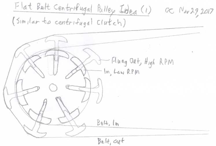 Initial Idea. However, since the belt is
directly on the weights, the weights on the right would fling open
while others stay closed.
Initial Idea. However, since the belt is
directly on the weights, the weights on the right would fling open
while others stay closed.
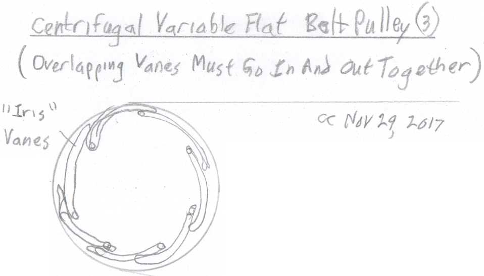 So a better idea would be to have them all
interlock somehow.
So a better idea would be to have them all
interlock somehow.
This needs more thought.
Back to a centrifugal
clutch (pictures follow text)
Having been considering the difficulties of making a
really good centrifugal pulley myself, and with this "disappearing
company" disappointment, I
decided to go back to the centrifugal clutch as the first method to
try. This opened up an unexpected problem. I couldn't find it!
Obviously I had put it somewhere after I had decided not to use it, but
I couldn't recall where and on the 7th and 8th I was utterly unable to
locate it again. I did however find
two large centrifugal clutches I had made some time ago, and on the
evening of the 8th I started thinking about them.
I had been mildly worried about the strength and gripping
power of the small diameter, rather narrow commercial clutch, and about
the heat it might generate at the high RPM it would operate at,
especially in stop and go driving. And if it dropped out too near the
activation RPM, the flywheel wouldn't have the chance to impart its
momentum to the car to start it moving. I thought about this some more
and started thinking that my larger ones were probably a more suitable
size for a car. Also I could adjust their operating parameters if
necessary with
various springs and even different weights. They were already
made, and the better one might actually be the best option. They hadn't
been successful as I used them when I made them, but the RPM was rather
low and the load quite high with just 3 to 1 reduction to the wheels.
Here the reduction after the clutch would be at least double that.
And
the RPM could be made still higher and the torque loading less by
adjusting pulley and drive sprocket sizes.
This time, the technique
of revving up a flywheel to store up energy to start the car moving
could be used, and I would configure the clutch so that once activated
it wouldn't drop
out until a much lower RPM. As I see it, what is needed is springs that
take a fair force - a considerable RPM - to "break away" and allow the
shoes to fly outward, then with the shoes out, have only a weak force
trying to bring them back in. Once the weight of the shoes has been
flung outward, the centrifugal force on them is greater, and (if the
springs can be configured as desired) the spring tension is weaker, so
that only a considerable slowing down of the drive will cause the shoes
to retract again. With the car in motion, they should stay engaged. As
they engage I expect there will be a considerable amount of slipping,
and here the choice of slick UHMW [ultra-high molecular weight
polyethylene] for the shoes and aluminum for the drum to carry heat
away, will prove to work better than most possible materials or
combinations.
I eventually found the commercially made centrifugal
clutch in a box I had recently put all my spare V-belt pulleys in and
put away in a storage room.
Some detailed design considerations (11th)
I decided the car wheel, even as it bounced up and down
and even if it went forward and back a tiny bit, would have to be
responsible for keeping itself pointed straight forward and back, and
for not tilting vertically. That would mean the bar from the wheel to
the mid shaft need only maintain the distance between sprockets, not
shift the mid shaft's position and angle to keep the drive sprocket in
alignment
with the wheel sprocket in all directions. That allows for a light bar
instead of a very stiff and heavy one.
Then all the sprocket on the mid shaft has to be is
aligned with the wheel, and thus in line with the wheel sprocket which
is
presumed to stay straight itself. I noticed on my large chainsaw that
the drive sprocket was free to move in and out a bit on a splined
shaft, to line up with the bar and chain. But on a car the drive
sprocket is much heavier, and it would tend to get pushed from left to
right a bit with the suspension and going around curves. It seemed to
me it should be fixed on the shaft, carefully lined up with the wheel
sprocket.
It was tempting to mount the centrifugal clutch on the
motor so its output would drive the V-belt instead of the chain. But
then what about the flywheel? The input side of the clutch isn't heavy
enough by itself. The more and heavier the pulleys between the motor
and the clutch, the more of the desired flywheel action they would
provide.
So the clutch would have to go on the mid shaft. And then
it would seem that in order that to hold the drive sprocket in
excellent alignment with the wheel sprocket, there would have to be two
bearings on the output shaft. And then two on the input shaft to keep
the pulley in line. That was starting to sound like trouble.
It became clear that a single shaft, an "inner" shaft,
should run right through from left to right, on two bearings. A shorter
outer "pipe" shaft on bushings or bearings would be free to rotate
against it until the clutch engaged. This after all is how the
commercial one was made. I was hoping to avoid reworking my clutch and
complicating the design, but it looked like the thing to do. Then, one
could toss a dice, but at first it looked easier to have the pulley and
inner side of the clutch on the bushings, and the output drum and
sprocket clamped onto the inner shaft.
Then I thought that if I could bolt or weld the side of
the drum to the chain sprocket, I could put a bronze bushing, 7/8" ID
and 1.0" OD inside. Then I would turn the shaft down to 7/8" on that
side to slide against the bushing, and use a 7/8" bearing for that end
of the shaft. It seemed I had one such bushing, purchased at Princess
Auto before I moved. I really needed two to get the length. (Two come
in a package... where did the other one go?) If need be, I could turn
down a 7/8" ID x 1-1/8" OD bushing to 1.0" OD. I had two of those. Sigh!
Then on the 14th I went to the automotive store and
ordered two suitable bearing holders. On the 17th I went to where there
was internet and found Princess Auto on line, and ordered more bronze
bushings, and a 1.125" tapered locking hub for the motor to hold a
pulley. (along with some things for the bandsaw alaska mill)
On the 19th I met with someone else interested in
converting cars and in electric powered boats. He ran rock crushing
machines and had much mechanical experience. He thought that for my car
design,
with 8 inch V-belt pulleys, at least triple pulleys running 3 V-belts
would be a good number. Ouch! Having heard that, my sense of proportion
now says he's probably right, so I'd better leave extra room to allow
for more belts. But it's the motor with its short shaft, and mounting
bolts sticking out the same face so you can't connect in close either,
that concerns me. Will it really handle a triple pulley, or will it
work loose and fall off? Such a powerful, high speed motor, and so
little to attach anything to! Perhaps 12" cast double pulleys might be
good - a little shorter, and they would also be good flywheels. But the
pulley's mounting hub sticks out well past the end of the motor shaft,
and it's
worse if you allow for even a thin mounting plate (or bars), bent back
around the edges to clear the pulley rim - and it ought to be a good
thick flat plate to hold the heavy motor. To stay out of the way,
inside the mounting holes, a 6" pulley would be the maximum. Maybe I
need to use a chain from the motor to the mid shaft? I guess in theory
that should work just as well as a belt(s) except for needing
lubrication.
Then I looked at a 10" pulley with a flat ~1/8" plate
body. It attaches to the same weld-on hub as the chain sprockets, and
gives more clearance for the motor mountings. Not much weight as a
flywheel, but it looked like it just might fit. The mid-shaft pulley
could be the heavy one. If 10" was too small, 12" was doubtless
available, and hopefully at that size, one V-belt would be enough. (Ya,
2 would be better.) I
didn't have the right hub (for 1-1/8" shaft), but I had ordered one
"just in case" in my 2nd Princess Auto order.
I also note that the little commercial centrifugal clutch
would look pretty scrawny beside a large 2 or 3 belt pulley. Ditto with
the small variable pulley. So I think
using the larger centrifugal clutch I made last year is the right
decision.
This friend also mentioned "A" and "C" series V-belts, the
larger letters having wider belts. Perhaps I should be after the
"specialty" larger sizes?
I had also heard he knew where to get a centrifugal
variable pulley, but when we met he pulled out a 2013 Princess Auto
catalog with the same Hoffco-Comet units that I had found on line that
are no longer available.
On the 24th two bearing holders and a 7/8" needle bearing
I had ordered arrived, along with some more 7/8" x 1" bronze bushings.
Those should do for the part of the centrifugal clutch that doesn't
turn with the shaft. (I already had a 1" needle bearing for the other
end.)
The more I checked it out and thought about it, the more a
chain seemed to be a better fit than a belt. By picking relatively
small sprockets,
like 28 teeth, that includes to fit it physically onto the motor shaft
still
with room for the motor mountings. And it would most likely be more
efficient - have less friction - than 2 or 3 V-belts. Why was I using a
V-belt(s), again? Let's see... it was the only option for a variable
pulley system. Likewise, a slipping belt clutch could hardly be done
with a chain. With the centrifugal clutch, it's not needed. On the 26th
I placed yet another order: another 28 tooth #40 chain sprocket and
1-1/8" hub, and some more #40 roller chain. (An incentive was a 'sale'
ending that day by Princess Auto on 64 drawer storage drawers for small
parts, which I need for my electronic components, which are becoming
increasingly disorganized as the variety of them increases.)
I may not be getting any assembly done as I work on other
things, but the plan is improving and I'm stealthily gathering the
parts I'll need when I do get at it.
Three views of the midshaft components:
* Mounting piece (attaches to car... somewhere, somehow)
* inner bearing holder & bearing,
* inner chain sprocket, from motor
* centrifugal clutch: inner part and outer drum
* outer sprocket, to wheel
* outer bearing
* outer mounting piece.
Either the inner sprocket and the center of the
clutch will need to be on bronze bushings (bottom
right) to turn together and independently of the shaft, or the drum and
outer sprocket will.
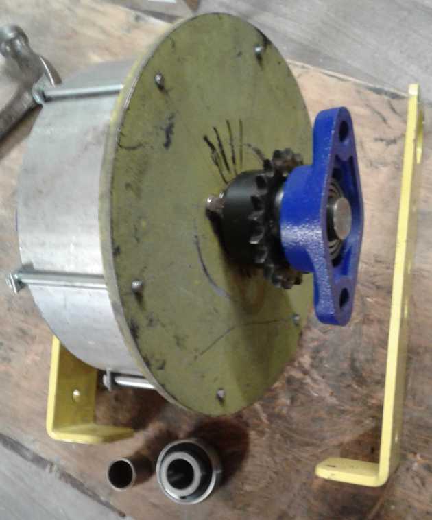
But the drum needs to be back a way from the
outer sprocket,
in order to be behind the lower body panel and under the car trunk.
(It'll need a longer shaft for that, and still longer to accommodate a
flywheel.)
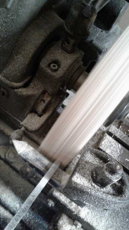
Double Set Screws: Make sure it won't come loose
(5th.) I had a hard time getting the coupling for the
Suzuki Swift off the motor shaft. I loosened the two set screws, but I
had to wind it off with a bearing puller with considerable force. Once
I had it off, I could see I hadn't loosened the set screws enough. Huh?
When I looked into that, I discovered the real problem: there were two
set screws in each hole, one screwing onto the other as an additional
clamp to hold it in place. Thus I had only loosened the outer set screw
and left the inner one still dug in, one into the shaft and one into
the shaft key. The key slid out with the coupling. The other went into
a shallow hole drilled into the shaft. My pulling it off seems to have
turned it into something of a slot. I had anticipated such a hole, but
of course no matter how far I unscrewed the outer set screw, it hadn't
helped at all.
I guess they didn't want the coupling, transferring all
the power of the motor to the transmission, to come loose on the shaft.
Both the hole and the double set screws seem like very good "tricks of
the trade", as they say, to use when doing similar shaft mountings. Of
course disassembly is easier when you know or figure out how it was
assembled.
Other
"Green" Electric Equipment Projects
Plan for a
Portable Bandsaw "Alaska Mill" for cutting lumber?
(Continued from #113)
Reconsidering on the 4th, I started thinking that the
project wasn't a difficult one, and that there should be a good market
for such a saw if it worked well, with a more realistic potential
profit margin than with most of my product endeavors. Instead of
"someday, wish list" I decided to move it to the top of the project
priority list. Making a good living for a change sounds appealing.
I had been thinking of using 14" bandsaw wheels like my
stationary bandsaw uses. On reflection, I'd like to make it as light as
possible, and cutting with the chainsaw with a maximum 26" cutting
width (30" bar) has convinced me wider is better. I was cutting off
branch stubs
and even into the wood with the electric chainsaw so the mill could get
past the wider parts, and I wasn't even into the widest base section of
the log. Cutting wide takes more time, but having to stop and cut out
chunks that make the log too wide to cut takes even longer. I'll have
to plan my cuts carefully for the
base section, or use an even longer bar and chain. (I found a 36" bar
with chain at a garage sale, but the chain is pretty worn out and the
bar needs straightening. ...When I finally tackled the fattest section
I
had to make quite a few cutouts before even the 36" bar could squeeze
in, doing a maximum 30" wide cut.)
12" wheels would be lighter and the same
overall width of saw will have 2" more cutting width in the middle. As
long as the band will readily make the tighter bend, I'm for it. It
does however limit the depth of cut, probably to about 4-1/2 to 5". I
don't think I'd want to limit the depth to much less than that, so 9"
wheels (the smallest common size) are out. Flexing a 3/4" band by hand,
I didn't think I'd want to run it on much less than 12" wheels anyway.
Notwithstanding the desire for more width, I may size my
first model to use the same 105" bands as my regular bandsaw, which
cuts almost 12" thick max. With the smaller wheels, that's likely to
give about a 20" maximum cut width. That's probably also more suited to
the small skill saw motor I plan to employ to power it. Also, while
there's a good bit of timber on my acreage, the four spruce trees
already cut down by the house were the largest, so the need for
absolute widest
cutting width decreases after these are done.
I had this vision of finding some scrap bandsaw and
taking all the useful parts off it - wheels and shafts, blocks, pulley
and so on. Realisticly that was pretty unlikely to happen. I could
order
wheels off e-bay - ugh. Some people were showing making wooden bandsaw
wheels and parts - even a whole wooden bandsaw mill - on Youtube. I
thought
I'd go with making plywood wheels if I didn't find any others by the
time I was ready to start. I didn't, and the guy at the landfill said
he'd never seen one show up there. (Perhaps I'll spray "flex seal" from
the spray can
around the outside, and not bother with tires.)
The design continued to take form in my mind that night,
and the plot thickened. Or at least, the potential cutting depth did.
If the axles of the wheels were mounted under the cross bars frame
instead of centered on them, the frame would be above center and the
available cutting depth would be thickened with the same size wheels.
Not a "C" frame but perhaps a "[" frame.
For 12" wheels, perhaps 7" would be available, or it could be made
deeper yet with more offset. The slotted bars sold for Alaska mills
seemed ideal for the main frame of the bandsaw.
"Prior Art": Tales of a previous bandsaw alaska mill
A neighbor said a bandsaw Alaska mill had been tried on
Haida Gwaii about 20 years ago. Evidently it wasn't a hit, but it
sounded to me
like the problems were in the implementation, not in the idea. (Rather
like some of my car transmission projects.)
The engine apparently compared unfavorably to a chainsaw
engine, so it sounded as if something like perhaps a lawnmower or
rototiller engine was used. That would be heavier and more cumbersome.
I plan to use an electric motor for the prototype. For a gas model, an
obvious choice would be to use a chainsaw engine: small, light and
flexible. Being
the very same engine it would be impossible to blame it in principle
for any shortcomings versus a chainsaw mill engine.
A second objection was that one was taking one's chainsaw into the bush
anyway, whereas the bandsaw was an "extra" tool having no purpose other
than milling. But this is surely a matter of application. I don't
really want to take an electric mill into the bush anyway. But
I do want to cut my big blocks of wood into dimensional lumber without
wasting so much as sawdust. And the chainsaw mill certainly burns a lot
of gasoline. I want to do it much quieter and cleanly. But except for
the smallest of jobs, I don't think a gas bandsaw mill in the bush
would be a
waste of capital, vehicle space or time - if it works better
than the chainsaw mill for even some of the cutting, it's worth having
as a labor saver.
The other problem noted was that it didn't seem to cut
bark well. Evidently the wood being cut was western red cedar. It's
soft enough wood, but its bark rips off in long stringy strips. It was
probably getting caught in the wheels and jamming things up. There are
a couple of solutions to this. The first is to put in a "catcher" or
"deflector" of some sort by the exit band guide blocks to deflect the
bark and sawdust out of the saw. The other is to not cut red cedar.
(Awful stuff to cut anyway, with long splintery sawdust that sticks in
clothes and is carcinogenic.) I forsee cutting spruce and probably
alder. The deflector is probably still a good idea. Perhaps the exit
guide blocks could be shaped for that dual purpose.
Back to the design
Finding a couple of wheels, it appeared that 11" wheels
would give a 105" band a cut up to about 22" to 24" wide, on a frame
under 36" long to hold the wheels and motor. 105" x 3/4" is also about
the largest band one will readily find prepackaged in a store, and is
the
size my bandsaw uses. That seemed like a good size to start with if I
could find or make such wheels. (I'd much rather find them than make
them, but I didn't come up with anything.)
On the 10th I decided to shrink the pulleys a bit more yet
to
10". I don't think that's beyond the "radius of elasticity" for typical
3/4" cutting bands, and the smaller the wheels, the smaller the saw can
be. And with the axles now being below the frame "backbone" instead of
in-line, a
6" cut depth should still be possible. But a special motivation for 10"
wheels was that's the largest size I could turn on my machine lathe if
I had to make them, as it appeared I would.
10" wheels would give the 105" band a 27" cutting width,
but the axles would be over 36" apart, which would make construction
with the 36" bars tricky. The next band size down I think is 93". I
have one because it's what my bandsaw took before I added a 6" riser
block so I could cut guitar backs, up to about 11" thick.
(93"+6"+6"=105"). It appeared the 93" band would reduce the cut by
(surprise, suprise) 6", to 21". But then I could easily mount the
wheels shafts on "pillow block" bearings which a store here could order
for me, without their mounting holes exceeding the 36" frame length. Of
course, frames longer than 36" can be had, and with a little silver
soldering a band of any desired length can be made. But perhaps for a
first attempt - with a 120 V motor of just 2 HP or so - I should be
happy with a maximum 20" wide, 6" deep cut (or thereabouts) in a 36"
frame with an off-the-shelf band, and consider that it can still be
very valuable for cutting smaller logs and for dicing up the cants from
larger ones into lumber, rather than to deal with splitting the largest
logs itself. If it works well enough, it could potentially replace my
7.5 HP electric sawmill on tracks, and it could undoubtedly be made for
a lower cost than any bandsaw sawmill on a track, which opens up
manufacturing possibilities.
Later I could try upping the power and dimensions with a
gas model using a chainsaw engine. I visualize attaching the chainsaw
motor driving a V-belt pulley instead of a bar and chain, and using its
two bar bolts and nuts to attach it to the bandsaw frame. I could see a
saw like that
that ripping through big logs like a demon! A potential advantage from
a manufacturing point of view is that it could be sold for lower cost
without an engine, leaving the buyer to attach his own chainsaw power.
I hope the trigger isn't too awkward - it'll be in an even worse
orientation than on a chainsaw Alaska mill. But people manage those
okay. Then again, if it was placed at the right hand side instead of
the left, it would probably be quite okay. The operator would then walk
down the right side of the log instead of the left.
Note: In checking out wheel sizes and band lengths, I noticed
that the teeth on the band were pointed the wrong way for the
envisioned cutting direction. I twisted the band around and found it
wasn't too difficult to turn it inside out, which reversed the teeth.
Problem? No problem!
Geering Up and Starting to Build
I bought a pair of 36" extruded metal Alaska mill rails,
which happened to look like a very good choice to be the bandsaw's main
backbone, on the 7th. From a local automotive store I ordered four
"pillow block" bearings for 3/4" shafts on the 14th, and on the 17th
from Princess Auto, I ordered "H" taper-lock hubs. (On the way home
after placing the order, I remembered I had no 3/4" shaft and should
have ordered some, and that I should have also got a couple of 7/8" and
1-1/8" shaft weld-on hubs in case I might need them for the car
project. Shopping is definitely easier living in a major center, and
with real internet access at home.)
That day I also dug out a piece of 3/4" birch plywood and
cut out four 10" discs [on the bandsaw, of course!] and glued them in
pairs to make two fatter discs (1.5") to use as bandsaw wheels with the
taper-lock hubs. I had the thought that for production,
molded PP-epoxy wheels could be very, very light, and strong. (That
would mean getting the new CNC router working to make the molds. Should
I really have traded the old, working CNC router for a new model that
now needs to be set up, both in hardware and software? But the old
heavy one took up a lot of space, and it was a lot of weight that I
didn't have to move up to my new home.)
 The next day
(18th) it was raining and almost freezing, so
I decided to work on making the bandsaw mill wheels and pass on trying
to roll the big log 1/4 of a turn and then Alaska mill another big slab
off it. I sanded the outside rims as smooth and round as I could get
them by eye on my stationary [belt &] disk sander.
The next day
(18th) it was raining and almost freezing, so
I decided to work on making the bandsaw mill wheels and pass on trying
to roll the big log 1/4 of a turn and then Alaska mill another big slab
off it. I sanded the outside rims as smooth and round as I could get
them by eye on my stationary [belt &] disk sander.
I didn't have the 3/4" shaft "H" hubs yet, but the 1" ones
were the same except for the center hole, so I could use one to get the
wheels done. I marked and drilled out the center holes: a tapered "H"
hub center hole and 4 mounting bolt holes around it. I wondered how on
Earth I was going to mount the wheels on the lathe to shape the center
holes, to 1.6" at one end tapering to 1.5" at the other. But the holey
gods were kind that day. I drilled the center holes with a 1.5" flat
blade drill bit in a hand drill, as my drill press won't take a 5" wide
item. What with boring through the thick pieces and angling the drill
back and forth a bit to get it to cut, the hole proved to be already
almost the ideal size and taper, and the hub inserted into it without
doing anything more. (A few file strokes could get it fitting in closer
if desired.) Then I looked in the lathe paraphernalia box and found a
holder I had made for making small gears. One end had a #2 Morse taper
to fit into the lathe spindle and the other end was a 1" shaft -
perfect to hold the 1" "H" hub! Everything was so close to maximum
possible
size that I had to assemble it all on the lathe, and disassemble it in
order to remove it, but it just fit - the 1.5" thick, 10" diameter
wheels just fit on, both ways! I contrived to use the tool holder with
a steel milling tool as a rest for the wood chisels, and that too was
just barely able to reach the right position in front of the wheel rim.
On the lathe I trued up each outer rim to one diameter all around, and
then honed the edges to give it a little "wooden barrel" convexity to
keep the band running centered. By suppertime they were finished. I
trust that was one of the bigger jobs for making the mill. (Let's see,
what else is there?... making and assembling the frame parts, mounting
and connecting the motor, making entry and exit blade guide blocks and
holders for them, making the cut thickness adjuster, making the water
drip blade cooling system, making a sheet metal(?) body and guards to
make it safe... Okay, it won't be done in a couple of days!)
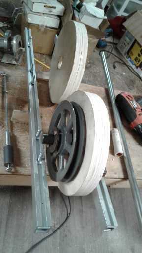
Sizing
things up. The tool on the left is
the one that allowed me to mount the
wheels on the lathe.
 After doing a sample fitting it seemed to me that 6" from
front to back seemed excessively wide, but various parts thicknesses
added length to the shaft. I reflected that 1.5" thick wheels were
somewhat overkill for .75" wide saw bands. On the other hand, they
would handle a wider band if I could find one (from somebody's bandsaw
mill?) in case that seemed to cut better, so that made them better for
a prototype. What I could have done was make one full 10" plywood wheel
piece and cut
out the center of the other one so it was just a rim. It would have the
same outside shape but the center would be thinner and the pulley
center could overlap it - it would be thinner, and lighter. (I'm hoping
to keep it well under the weight of the 40 pound chainsaw with mill,
which I can barely handle. The lighter the better! The wheels weigh 915
g each - about 4 pounds total. Their hubs add another pound. That's 5
pounds out of... 30?)
After doing a sample fitting it seemed to me that 6" from
front to back seemed excessively wide, but various parts thicknesses
added length to the shaft. I reflected that 1.5" thick wheels were
somewhat overkill for .75" wide saw bands. On the other hand, they
would handle a wider band if I could find one (from somebody's bandsaw
mill?) in case that seemed to cut better, so that made them better for
a prototype. What I could have done was make one full 10" plywood wheel
piece and cut
out the center of the other one so it was just a rim. It would have the
same outside shape but the center would be thinner and the pulley
center could overlap it - it would be thinner, and lighter. (I'm hoping
to keep it well under the weight of the 40 pound chainsaw with mill,
which I can barely handle. The lighter the better! The wheels weigh 915
g each - about 4 pounds total. Their hubs add another pound. That's 5
pounds out of... 30?)
I decided to total up some weights to get an estimate for the total
weight:
ITEM (qty)
|
WEIGHT (grams)
|
TOTAL (grams)
|
Wheels (2)
|
916
|
1832
|
Hubs (2)
|
275
|
550
|
Axles (2)
|
300
|
600
|
Aluminum 6" pulley (if 6" is a good size - my other pulleys
are heavier.
But an 8" or 10" pulley might be better: slower saw band with more
torque.)
|
246
|
246
|
Backbone (2 pcs)
|
841
|
1682
|
Pillow Block Bearings (4)
|
500 (?)
|
2000
|
3/4" x 96", 2 teeth per inch, saw band
|
242
|
242
|
Motor (Ryobi Skill Saw)
|
quite close to 5000
|
5000
|
That wasn't an all-inclusive list, but
it came to 12152 grams or 27 pounds. By the time the case and
miscellaneous parts were added, the saw might be around 35 pounds -
hopefully not more than 40 with the cutting depth/slide rails ("Alaska
mill" parts) included. So much for my 30 pound pipe dream!
A lot depends on the motor's weight. Now, where are those
OEM lawnmower motors to be found? I'm sure they're the best: 120 VDC
motors (with a diode bridge to run on AC) and permanent magnet stators,
available up to at least 12 amps. No electricity wasted in field coils,
so maximum mechanical output power per amp. (120 V * 12 A = 1440 W =
1.93 HP.) And not so much over 100$. I think those are the motors for a
production unit.
OTOH Ryobi skill saws complete with motor are around just
60$. And to mount it, one might just bolt down their base plate to the
unit. Then the cutting depth adjustment becomes the belt tightening
adjustment.
But after I run the saw with the Ryobi, I could
temporarily remove the 12 amp motor from my own electric mower and try
it out for comparison.
I digress with various thoughts and no actual progress
because I was waiting for the ordered parts to
arrive. The pillow block bearings were supposed to arrive on the 19th,
but they still weren't there on the 21st. I needed them and the 3/4
inch shaft to start sizing up the overall assembly.
Milling with Chainsaw Mill (might a bandsaw do better?)
In the
meantime I continued milling with the chainsaw. I
rolled
the big log 1/4 turn with a hydraulic trolley/floor jack, a bit at a
time,
wedging pieces of wood under it so it wouldn't roll back. On the 20th I
finally had the flat board mounted on top and I cut the rough first
slice off the top - and then into firewood pieces. On the 21st I cut
two 6"
thick slabs to make 16 foot 2" x 6"es out of. The very first slab cut
earlier before rolling the log was mostly 30" wide, that being the
maximum width the 36" bar attached to the mill could cut. (Several
protruding chunks and some of the butt end had to be cut from the log
to narrow it so that the mill would fit on.) That cut took around 14
minutes of
actual cutting, excluding time spent putting in wedges and refilling
the gas and oil part way through, and for me a few very brief rest
breaks out of the exhaust and noise. As always it excludes the time
spent sharpening the chainsaw and refilling the gas and oil - with
every slice. And the time starting the saw, which sometimes went well
and sometimes was exhausting in itself, when 10 or 15 pulls did nothing
and it required removing the spark plug and giving it a dozen pulls for
no apparent reason (wasn't flooded) before it would fire when
reassembled. After rolling the log, the top cut at right angles to the
first ones took about 7 minutes for a roughly 18" cut. On the 21st I
cut two slabs, one in the morning and one in the afternoon, each taking
10 minutes of actual cutting, yielding two 6" thick by roughly 24" wide
slabs with one bark edge, 16 feet long.
After being diverted for some days, on the morning of the
27th I went to cut the log into the last two pieces. The saw wouldn't
start. I spent more time trying to start it than I would have spent
milling. I finally threw it in the car and drove into town with it to
the dealer - another hour driving, tho not entirely for just this one
thing.
The dealer changed the spark plug and it started with one pull. I
bought a spare spark plug. Late in the afternoon I got back to the log.
Again it started with one pull. Wow! Almost all the way through, the
saw ran out of gas. I guess it only holds enough for about 12 minutes
of cutting. After refilling it it took a number of inconvenient
sideways pulls to start again, from being warm and turned sideways in
the
log, but it did start and I finished the cut. I made this one 8" thick
instead of 6", to cut some 1" x 8"s or 2" x 8"s from.
The remaining
bottom piece was also
about 8" thick, but one edge would be bark and irregular, so the boards
will be narrower - 6" if standard lumber dimensions are adhered to. It
would have been thicker - over 9" - except that three of the chainsaw
cuts turned over an inch thick of good wood into sawdust. A bandsaw
would have saved most of that and probably allowed some 8" boards. (The
top cut on the log doesn't count as wasting good wood because the
sawdust theoretically comes out of the top scrap piece, so I only count
3 cuts [9/8"] instead of all 4 [12/8"].)
This last cut took about 13 minutes of actual cutting, in
spite
of being a somewhat thinner cut than the previous two. That puzzled me
at first. I thought it was cutting fine. Did I not sharpen the chain as
well as usual?
Then I remembered I had seen a couple of sparks as it
passed a protrusion where a limb had been, near the start of the cut.
It would seem there were a
few chunks of gravel embedded in the bark. That side of the tree had
been lying downward, for months, and the rocks must have got pressed
in. I don't suppose bandsaw bands will
like sand and rocks any better than the chainsaw chain does. (For city
trees, carbide teeth that would cut through embedded nails, hooks and
clotheslines was one important advantage of my pivoting circular blade
mill, small and slow as it is. I suppose it would do loose bits of rock
without much problem too. Hmm!)
The point to writing here of these chainsaw milling
activities
is to illustrate what it is hoped that bandsaw mills can replace. If
it's easier to push and cut
with, or if it cuts faster for similar effort, I for one could do more
cutting. And the cuts should be smoother. So far I
haven't managed more than two cuts in a day. I've averaged at best one
per two or three days from: saw won't start, taking the saw in,
brushing off the rust and straightening my new (used)
bar, and a couple of new chains (after wrecking one... all this 'prep'
stuff is done now, I hope!), and from
cutting off protrusions and carefully setting up the top board on fresh
log surface for a straight, flat cut, which I've now done 6 times for
the three sections of log. (The bandsaw alaska mill won't fix that
headache. But I just might come up with a better technique!)
With a maximum 20" wide cut this first electric mill won't
break down the biggest logs that the chainsaw with the 36" bar (30"
cut) does. But it should be able to do the smaller ones, and it
certainly should be able to cut the big cants made by the chainsaw into
useful lumber sizes, without making much sawdust.
I've saved a couple of smaller logs, upper ends of the big
trees, to try the first "Carmichael Mill" out on once it's ready and
has reliably sliced a few boards off of cants.
Building Continued
On the 24th the bearings and the 3/4" hubs arrived on the
same day. I was still missing the 3/4" shafts to really start putting
things together, but I did a little test fitting that evening. It
appeared that the maximum cutting depth, by cutting right down at the
backbone, would be about 6-1/2". But this could be extended to anything
short of the 10" wheel diameter by mounting the wheels' "pillow block"
bearing holders on extension blocks. The possibility for cutting at
least an 8" thick slab off a log to then slice off boards or planks of
that width was attractive. That would need at least 1.5" standoff
blocks; preferably 2". Then again, if the blocks were 3" thick, the
wheels wouldn't protrude above the backbone bars at all, and a flat top
cover could be used instead of a shaped one. But the thicker they are,
the more solid and well supported they and everything will need to be.
On the 28th the 3/4" shaft finally arrived. I cut off a 6"
piece for the end with the pulley and 5.25" for the other end. Fitting
everything together so it all turned smoothly turned out to be one of
those simple sounding jobs that take several hours. The "H" bushings
wouldn't tighten sufficiently against the shaft in the wooden wheels to
lock them on, and it needed four 3/4" ID washers on the shafts to keep
the pulley bolts from hitting the bearing mounts, but amazingly I had
just that many. By evening I had the basic assembly but still with a
couple of things to change that would require disassembly again. One
wheel wobbled badly and the washers I had used for the
tightening/adjustment bolts were too small and were just digging into
the wood. (Aren't washers supposed to spread out the load? These days
they seem to make them too small and so thin they bend into a cup when
tightened. What's the point?) I disassembled and fixed it later.
It turned out that with the 93" cutting band the bearing
holders were almost exactly right at the ends of the 36" extruded
tubes. Can't ask for better than that! I mounted the pulley on a
protruding axle behind the frame instead
of between the two pieces, in order that it wouldn't have to be
disassembled to
change the V-belt. The cutting band fits around both wheels, so it can
also be easily changed.
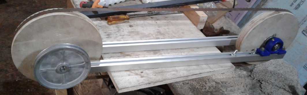 The essential frame of the saw, upside down.
10" x 1.5" plywood wheels,
lightweight 6" V-belt pulley, 93" cutting band.
The essential frame of the saw, upside down.
10" x 1.5" plywood wheels,
lightweight 6" V-belt pulley, 93" cutting band.
With the band on and no case I had to set it on a thin board - one end
of my
radial arm saw table.
Right way up. If nothing sticks down from the frame
in the cutting area, the maximum cut depth is over 6".
I spun it around with the pulley (already watch yore
fingers on those moving teeth!) and reflected that there's still much
to be done before it's ready to slice into some wood.
Electricity
Generation
An Attic
Windplant?
On about the 28th I was lounging in the bathtub and
hearing some whirring
vents this house has on the roof. Perhaps this idea is unique?:
Whenever a wind is blowing past a house, there's a high pressure
windward side and a low pressure lee side. If one put one-way vents
into the soffits (and end walls?) that would allow air to enter but not
to exit, so pressure would be built up inside the attic by wind from
any
direction. Any wind would cause air to flow upward through a vertical
air pipe extending like a chimney through (or near) the peak. The wind
turbine is placed in the pipe. That's it in a nutshell.
All the moving parts would be in the attic, out of sight.
The air intakes would be covered by a screen. Even some floppy plastic
that lays over the screen, held along one edge, might suffice for "one
way vents". One could embellish this by having a swivel pipe on top of
the chimney, with a vane so its exit always points downwind, to
maximize the pressure drop through the chimney/pipe. If it's noisy,
perhaps some sort of muffler could be made for the air outlet.
I haven't tried to figure out what sort of power could be
made, or what airspeed might be attained by what wind. The airspeed
near the ground is lowered by obstacles such as houses, and it's
generally considered "the higher the better" for windplants. But
extensive
soffit vents could present many square feet of entry to rapidly admit
many
cubic feet air per second into the attic. So the air velocity in the
pipe (and hence the available energy) might be higher than one might
expect. The pipe should be pretty short and a fair diameter so as
to not be a bottleneck.
Consider a "regular" windplant with a 2 meter diameter
propeller - a pretty large home unit. That would have 3.14 square
meters of air across the blades at the full speed of the wind. Think of
'a sheet of plywood' to visualize this area. Now consider 3.14 square
meters of soffits or end wall allowing air into the attic. If the
chimney was .314 square meters (.632 meters or ~2 feet diameter),
whatever speed the air came in at would be multiplied by 10 on its way
out the pipe. That would be a pretty big pipe but a pretty small
turbine, easier to do.
Having thought of it, I don't think I'll try building it. The
results would obviously be very dependent on the building and the wind
conditions there. The effects of the air pressure in the attic might
have to be taken into account. All rather unpredictable. My place might
actually work out well, but I'd rather press on with the lambda ray
energy converter... after the bandsaw alaska mill... after hybridizing
the car...
http://www.TurquoiseEnergy.com
Haida Gwaii, BC Canada