Turquoise
Energy Ltd. News #115
covering
December 2017 (posted January 11th 2018)
Lawnhill BC Canada
by Craig Carmichael
www.TurquoiseEnergy.com
= www.ElectricCaik.com
= www.ElectricHubcap.com
= www.ElectricWeel.com
Features: A Decade in Review
Month In Brief
(Project Summaries etc.)
-
Internet - Shrinking World - Carmichael Mill ("Bandsaw Alaska Mill") -
Battery Lab & Nickel-Nickel Batteries - Hybridizing the Toyota
Echo... Wait, how about the Miles truck?
A Decade in Review
* What's been done?: Listing the projects
In Passing
(Miscellaneous topics, editorial comments & opinionated rants)
- Sea Foam is natural (Ooops!) -
Cryptocurrencies - Fraud in the Stock Market? - John MacAdam -
Carmichael
Projection World Map & Virtual Reality
- Project Reports
-
Electric
Transport - Electric Hubcap Motor Systems
* Ground Effect Craft: Fixing Lateral Stability Problem
Other "Green"
Electric Equipment Projects
* "Carmichael Mill", a "Bandsaw Alaska Mill" - Meat cutting band is
better(?) - Building It, continued - Home Sheet Metal Tools - Motors
and Duty
Cycle - Drive Belts
* Power Supply: Photos Simplify Repair. But is it worth it?
Electricity Generation
* Tiny Solar Cells (purchased)
* A couple of VHE Ray Energy Notes
Electricity Storage - Turquoise Battery
Project (NiMn, NiNi, O2-Ni), etc.
* Another round with Nickel-Nickel chemie: in oxalic acid - Battery Lab
- Chemistry - electrolyte - Building a Cell - Expectations: The
Reactions - Testing & Observations - Conclusions - Next
Electrolyte: Potassium Oxalate? - Cell with KH(C2O4)? - Positive
Electrode Characteristics (seemingly Favorable: with slightly lower
voltages)
December in Brief
Here's another late newsletter... so much to do, so
little time! I spent a couple of weeks in Victoria with family for
Christmas, which definitely ate into December's project time. Then at
home there were things to catch up on. Then after 10 years, it took
quite a while to look through the TE News indexes at all the tables of
contents just to find and list all the projects - successful or
unsuccessful, one time or ongoing, and finished, unfinished, barely
started or just envisioned. (My multi-millions "dream list" budget that
would really get things going will come next month.)
Internet!
My friend Tom, having moved to Skidegate, managed to get
internet via a radio link from Gwaii Communications. (My place is out
of
range of their system.) I visited him a lot to use it, and especially I
left a computer there for well over a
week and got my bitcoin wallet
updated after 7 months off line. Then I sold the last of my bitcoin at
what seemed like a great price, just before it doubled again and more.
People in China have been getting into it in a big way, and there are
1.4 billion of them. And there are many others as well, especially in
those lands where the local currencies have been proving most
untrustworthy.
I finally figured out a means to get basic internet at
home and
got it working in late November or the start of December. In October(?)
I asked my next door neighbor, thinking he had satellite internet, if
he would share it via WIFI in exchange for splitting the monthly
charges. It turned he just had the satellite dish left over from when
he had had it, still mounted on his house. I bought the dish off him
and phoned to ask about getting satellite internet installed (now that
I had one of the costly pieces). Somehow I got no reply to my
message.
In the meantime, I aimed the antenna dish two acreages
over and
put a WIFI repeater in its focus. I found I could pick up the closer of
this person's two satellite systems. I had internet!... sometimes... If
the
WIFI gods were smiling. But at least
sometimes
along with everything else internet does, I could search and
order things on line from home again and do research on
line again. In mid December I was in
pursuit of chemical information in attempting to make nickel-nickel
batteries.
After Christmas I put the dish in a new location and it
seems to be working better. I also discovered one of my computer
tablets was frapping out and saying it was off line, which of course I
had been attributing to loss of signal at the repeater.
Shrinking World
When I worked for the federal government ministry Transport
Canada in the late 1970s, electronic technicians were still often
posted at isolated northern posts to maintain equipment,
and one got "isolation pay allowance" for working at one. I think
Sandspit airport was one such place. And even in Victoria, a fair size
city, electronic components could be hard to come by. (Someone tells me
one can still get income tax advantages for living in a "semi isolated
locale" such as this one, including for moving to one for work. If I
can write off my moving expenses I will certainly owe no income tax for
2017!)
Today with the internet, one is much less isolated in "out
of the way" places than in those times - which were doubtless better
than still earlier times. From anywhere electronic parts can easily be
ordered on line from several major sources who will have everything in
stock. But I've done that before. I really felt less isolated when I
started ordering mechanical parts for the bandsaw mill. I started out
very apprehensive about being able to get them. Then I went to
PrincessAuto.ca and found I could get everything on line that I could
at
their
store in Victoria, and probably more as the mail order depot was less
likely to be out of stock on any item. It would arrive in a week or so
by mail (as fast as any mail gets here). I was however glad that I had
seen all those actual parts in their Victoria store and knew just what
they were and what to order. I also know there are other common
mechanical
parts that they don't have, and when I need these they may be harder to
track down. (Small ball bearings, for example. I didn't find a Canadian
source and finally had to order
some from VXB bearings in the USA again. But then I found some more at
"Mac's Auto Electric" when I went to Victoria for Christmas.)
If ever practical ground effect craft are made and put
into service, such vehicles (unless supplanted by something even better
like
anti-gravity flying craft) could make mountainous coastal areas and
isolated islands, such as abound in northern BC, still more accessible.
Carmichael Mill ("Bandsaw Alaska Mill")
I explored and ordered "meat cutting bands", which proved
to be substantially thinner than "wood cutting bands" (and seemingly
much resistant to rust), and hence should cut more easily, giving
perhaps 3 HP-like performance from a 2 HP motor. This could make
considerable difference in the viability of the plug-in electric model.
To my surprise the price was similar, and I started wondering why they
make the thicker "wood cutting" ones at all.
I worked on it until the 9th and the assembly was well
underway.
Then I went to do small
ball bearing races as little guide wheels. I needed 6 and had 3. They
didn't arrive and didn't arrive (and in fact came after the new year).
It got a little frustrating. I did get the meat cutting bands and I put
one on.
The next question was a motor. I had meant to just mount
the Ryobi skill saw on top, but a company on line was advertising BLDC
motors that sounded suitable. These would give the most mechanical
power from the electrical power available in a wall plug. It sounded
like it might cost 500$ or so, and would
be worth waiting a bit for. I wanted to give the new saw all the best
advantages I could since I not only want to try it out, but actually
put it to work milling some spruce lumber, and if possible attract
investment to make and sell them. Best not to needlessly make it look
underpowered.
But they didn't reply and I started
considering whether to take my own Electric Caik BLDC motor off the
outboard and put it on the saw. (I don't want to spend time making
another one - unless I can see how to improve the cooling for higher
and sustained power.) It could (for a time) put out as much power as
any plug-in motor, using 60 amps from a 24 volt battery. That could be
advantageous if one wanted to cut where no power was available. (Or a
generator could work too, and unlike the gas chainsaw it could be
placed downwind at a distance from the miller.)
Battery Lab & Nickel-Nickel Batteries
On the 10th, waiting for parts to continue the mill, I
started setting up my battery lab in the small laundry room. It was
cramped but it would have to do. I had to store a lot of whatever I
wasn't immediately using on shelves out in the workshop.
 I
decided to pursue the "nickel-nickel" battery chemistry
again. This time I would try oxalic acid as the electrolyte. It seemed
to work for a nickel-zinc test cell long ago, and potassium chloride
didn't work with a nickel negative side. So, instead of "lead-lead" in
sulfuric acid, it would be "nickel-nickel" in oxalic acid.
I
decided to pursue the "nickel-nickel" battery chemistry
again. This time I would try oxalic acid as the electrolyte. It seemed
to work for a nickel-zinc test cell long ago, and potassium chloride
didn't work with a nickel negative side. So, instead of "lead-lead" in
sulfuric acid, it would be "nickel-nickel" in oxalic acid.
But the experiment showed the oxalic acid unexpectedly
attacks metallic nickel spontaneously, and while the reaction product
isn't soluble, it does separate from the metal plate and precipitate
out. Perhaps instead of the acid an oxalate salt could be used -
potassium hydrogen oxalate or potassium oxalate - both of which are
said to form alkaline solutions. These can be made from oxalic acid (I
had to order more), and potassium hydroxide (which I have lots of). In
alkaline solutions I expect the nickel is less likely to react
spontaneously than in acid. On reading a research paper it looked like
adding still more KOH would give a mix of KC2O4 and KOH for a pH 14
alkaline battery, where the KC2O4 just might render metallic nickel
oxidizable in the KOH. This formula also might make a good electrolyte,
so there are several things to try out.
Somehow creating a new and better battery chemistry and
making better batteries (and ultimately production) has always seemed
to be just a hop, skip and a jump away, but so far I haven't hit a
magic combo with everything right. I am rather optimistic about
oxalate, however. It seems like just the right ion. It lowers the
reaction voltage of a nickel positive electrode just a little, quite
possibly just enough to solve my "bug-a-boo" self discharge problem.
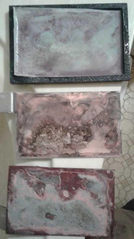
The cell and electrode
plates after adding electrolyte and
attempting to charge it for a while.
Hybridizing the Toyota Echo...
Wait, how about the Miles truck?
The last parts I thought I needed arrived in early
December. But as I thought about hybridizing the Toyota Echo I decided
to exercise the better part of valor and chickened out. It was
currently my only road vehicle and it was a long way to anywhere by
bicycle, and to make it all work there were a lot of parts to install
and wire up, besides just the motor
and transmission parts.
That didn't mean abandoning or further delaying the
project and
its main intent. If I did the Miles truck instead, it was already
electric and all that was needed was the basics: move the motor,
install the transmission stuff, and remove the original transmission
and drive shaft. I could work on it at leisure in the garage without
worries about getting places in the duration. I hoped to improve the
power and
substantially improve the range of the truck with this new
configuration, and hopefully it would be fit for the lightly trafficed
highway here even if it would slow down going up hills. Then I would
have both a small car and a small electric truck.
The two electric drive parts that had been destroyed in
the Swift fire were the meters above the dash. I was passing by
Canadian Electric Vehicles during my Christmas holiday. We determined I
didn't need one of them because of a meter I had that would do the job
(it had come with the Swift but hadn't been installed). The other one
was over 400$. Yow! Since I wanted it and wouldn't be passing by again,
I bought it anyway. But I wondered if I needed a sanity check to spend
so much on one little part.
On the 18th I was still waiting for bearings for the
bandsaw mill, and then for oxalic acid too. At least, I couldn't find
my tiny bottle of it. I may have already, before I moved here, mixed
the
last of it into the solution I was using, now virtually empty. Then
everything had to come to a halt anyway because I was going to Victoria
to see my family for Christmas, departing here on the 20th and
returning on my 63rd birthday, January 1st.
A Decade in
Review
 I
first visualized
and started in on the car hybridizing projects in January 2008, so
December 2017 completes an entire decade. The objectives when I
started were a wheel motor to mount on the outside of a car wheel, a
motor controller to run it, and some sort of as yet undefined new
battery chemistry that would be cheaper to produce and better than
lithium for electric transport - preferably with indefinite cycle life.
I incorporated Turquoise Energy Limited in March to help pursue these
projects and then hopefully commercialize the results. Without any real
timeline in mind, I initially thought developing such things might take
a year or
so. While I made an "outside the wheel" motor and controller that
(barely) moved my
car by October, I gradually started to realize that it was going to
take substantially longer to develop tried and tested products that
were reliable and safe beyond being (at least, I hoped) "cutting edge"
conception
prototypes. I started thinking in terms of three to five years. Little
did I realize I was in for a dazzling decade long string of novel and
exciting "green energy" projects, but always on a shoestring budget and
with only glimmering hopes of ever commercializing any of them.
I
first visualized
and started in on the car hybridizing projects in January 2008, so
December 2017 completes an entire decade. The objectives when I
started were a wheel motor to mount on the outside of a car wheel, a
motor controller to run it, and some sort of as yet undefined new
battery chemistry that would be cheaper to produce and better than
lithium for electric transport - preferably with indefinite cycle life.
I incorporated Turquoise Energy Limited in March to help pursue these
projects and then hopefully commercialize the results. Without any real
timeline in mind, I initially thought developing such things might take
a year or
so. While I made an "outside the wheel" motor and controller that
(barely) moved my
car by October, I gradually started to realize that it was going to
take substantially longer to develop tried and tested products that
were reliable and safe beyond being (at least, I hoped) "cutting edge"
conception
prototypes. I started thinking in terms of three to five years. Little
did I realize I was in for a dazzling decade long string of novel and
exciting "green energy" projects, but always on a shoestring budget and
with only glimmering hopes of ever commercializing any of them.
At this
point, there have been so many projects - successes, failures, and
those taken to various stages of completion or incompletion short of
definitely fitting into one of those categories, that I will here
simply list them, sometimes combining multiple segment
projects into one title. The projects seemed to need some basic
explanations, but for so many projects, the list started to get really
long by the time I was half done, in time spent as well as words. I
decided to save most of the descriptions for the newsletter indexes,
and I'll have to refer the reader interested in a particular title to
those (once I've done them) as well as to the newsletters themselves.
- Ocean Wave Power (the original project started in 2006)
- a small Pivoting Blade Electric Sawmill (built and cutting
hardwood lumber in 2006)
- Electric Hubcap axial flux BLDC 'pancake' motor. More than any
other project, this evolved from "golly it works", first into a highly
efficient motor, then into a safer, more reliable unit that might
actually be approaching one that could be produced and sold. Later, new
types of motors with amazing promises started to cross my path, and I
started diverting efforts into them.
- 'Turquoise' BLDC Motor Controller, for the motors.
- 'Turquoise Battery' (chemical ideas initially only vaguely
defined). Ni-Mn; Ni-Ni; Ni-Air;
nickel-manganates "+" electrode. Trying to create a viable new battery
chemistry has been an ongoing project throughout, and a number of
promising developments have taken place.
- Some lead-acid battery explorations: sulfate salts & "pulse
charging".
- A Variable Torque Converter/Transmission (only the objective
was defined - it sounded simple enough!). Like the new battery
chemistries, this has been an ongoing focus and many novel ideas have
been tried out over the years. Some of them are undoubtedly
improvements, but my constructions to date have not been robust enough
to put a car on the street with.
- EV Fan-Heater(s) to defog windshield quickly (nothing very
special here)
- Micro- or nano-crystalline coil cores
- Nanocrystalline titanium dioxide borosilicate "pebbly textured"
Solar Cell Cover Glass Project to collect more of the light (Cores
project above morphed into this, plus a couple of new ideas for dye
sensitized solar
cells!)
- Electric Outboard motor project with Electric Hubcap prototype
motor. (Later changed to Electric Caik motor outboard.)
- Pulsejet Steel Plate Cutter (Probably a good idea for CNC
cutting, but I didn't finish it.)
- Giant "Electric Weel" motor project, perhaps to drive car
wheel(s) without gear reduction (as built with similar techniques to
"Electric Hubcap" the case was too flexible - and it didn't work well
as a
generator.)
- I bought a Chevy Sprint, at first intending to do just a
'regular' conversion to EV to drive electrically. But soon I started
trying to apply my torque converter ideas instead so it would have
better range, and have never yet got it on the street.
- LED space & grow Lighting projects. (Globe lights, lamps
& flat panel lights - started in 2012 when LED lighting was
virtually unavailable).
- I dabbled in 'magnetic drives' but failed to make anything very
interesting or that powered itself. (I'm not convinced it can't be
done.)
- I came up with a way to use magnets with the Earth's field to
orient and accelerate an orbiting spacecraft, but didn't convince
anyone to put them on a small satellite that was being made.
- I put up some solar panels and made a 12 volt system. In that
project, I came up with a line of 12 VDC plugs, sockets, wall plates
and more for any sort of 12 V wiring. I called it the "CAT standard" -
Connectors based on AT fuses.
- I also made a "super insulated" peltier module shallow chest 12
volt fridge, about 4 cubic feet.
- I then dabbled with magnetic refrigeration using gadolinium -
thought I had a better, simpler design - but then figured better
peltier modules would soon be made and make it obsolete.
- I made custom plastic cases (3D printed) to hold 10 D cells,
which in NiMH makes a 12 volt battery.
- I conceived a CNC farming or gardening machine. (But haven't
made it.)
- The Electric Caik motor extended the Electric Hubcap
motor family down in size instead of up, with 2/3 of the internal power
components and running at 24 volts instead of 36. It was originally
conceived for electric motorbikes, but the prototype ended up running
the electric outboard.
- A bicycle wheel rim motor was conceived to power bicycles and
also using 6 of the same coils, but was never built.
- I put together a "Reprap Pro" 3D printer kit and got it
printing.
And all the above, with various overlaps in the narrative
and project time spans, covers the first five years, as detailed in
Turquoise Energy News #1 to #59.
- I tried making an evacuated tube heat radiator for the fridge.
Such a device transfers heat much more rapidly than copper or aluminum,
which might render a fan unnecessary. I couldn't get sufficient vacuum
in the tubes.
- I bought some thermoelectric generator modules (pretty much the
same as peltier modules, but instead of electricity in, different
temperatures out, different temperatures in generate a voltage. I
investigated using these for a woodstove thermoelectric generator.
- I thought that with peltier modules one might make a house or
electric car solid state heat pump using less electricity than with
radiant heating. If one could achieve a coefficient of performance of
1.0, and add that to the heat directly radiated by the electrical
inefficiencies, one might get double the heat. Attaining good results
looked less and less promising.
- I got an electric converted Mazda RX7 EV and tried mixing
battery types in it, charging each 12 volt section separately. Worked
well.
- I got a setup working to program TI's MSP430 line of
microcontrollers in assembly language. I conceived of several uses for
microcontrollers.
- I started investigating "bladeless" Tesla Turbines as well as
vertical axis wind turbines (VAWT.s). It seemed to me possible one
might put together a better VAWT, quiet and with the moving parts all
inside a housing, with the Tesla system. I took (not for credit) a
"coursera.org" course on "Wind, Waves and Tide" power from University
of Toronto an learned much about Earth's wind systems.
- I made an axial flux "switched reluctance" motor ("ARM" motor)
and a new type of "simpler" motor controller for it with only 3 drivers
(low side only) instead of 6. With solid steel rotors and almost no
back EMF, reluctance motors can turn at fantastic RPM.s safely and
easily, eliminating all need for variable gearing - a fixed reduction
will do fine. I didn't get it running very well (motor controller needs
work) before more promising new ideas started pouring in.
- After starting on the ARM motor, I heard about a "transverse
flux" BLDC motor. One coil per phase is wound around the entire stator
- so simple! It looked even more applicable to the reluctance motor
type than to PM motors.
- If seemed "Bedini" (or should it be "Houdini"?) unipolar motors
somehow got more out than was put in, a "Coefficient Of Performance
(COP) greater than 100%. It also seemed there were "Zero" motorbikes
that got fantastic range from their batteries, which seemed to indicate
it wasn't just hot air. It seemed short pulse driving was the key,
which would require more changes to a motor controller to accomplish.
- Then I heard of the idea of "electro-permanent" AlNiCo
permanent magnets. The motor controller would pulse the coil once to
"permanently" magnetize it, so the rest of that part of the cycle would
be two permanent magnets attracting or repelling each other. At the
correct points of rotation, pulses would magnetize, demagnetize or
reverse magnetize each coil. This seemed to have tremendous potential
for using less electricity to run a motor. (Perhaps the Bedini made use
of this.)
- Before I built anything using that idea, I heard about
"permanent magnet assisted" coils. Here there is a permanent magnet and
an electromagnet in each coil. If no current is applied, they short
magnetically through "keepers" and there is no external magnetism to
the rotor, but if the coil is energized to the same strength and
polarity as the magnet, they add together and the field is doubled
using the same amount of electricity. This seems to be a really neat
trick for cutting the electricity required in half. I planned how to
convert my reluctance motor to this system since it was readily
applicable. I didn't get that done either, but it holds tremendous
promise.
- I added opposite polarity magnets to the "unipolar" BLDC motor
between the other magnets, giving it 4 magnet poles where a regular
BLDC rotor would have 2. This enables it to be run from the (more
reliable?) "unipolar" motor controller instead of a regular BLDC
controller. I called it the 4:3 BLDC motor.
- I delved into aquaponics (with LED grow lighting), in which
fish eat fish food and their waste is pumped out to feed a vegetable
garden, which sends clean water back to the fish pond. For minimal
input one gets both fish and vegetables. It has great potential for
feeding people form a smaller space.
- I found there is a much higher top end to the electromagnetic
spectrum than gamma rays, identified in 2007, which appeared to be how
various people have pulled "free energy" out of the air, starting if
not with Nicola Tesla then with Thomas Henry Morray whose energy
machines in the 1930s or so have many testimonials from knowledgeable
people and government officials, and who recognized this higher
frequency band as being the source of the energy. When scientists
identified them in 2007 they were calling them "Very High Energy Gamma
rays" or "VHE gamma rays". Since it is far beyond the gamma ray area of
the spectrum and the effects are qualitatively different, I felt this
was a misnomer and I started calling it "Lambda" rays. But I could go
for "VHE rays" without the word "gamma" attached. (The space scientists
seem to have never entertained the idea that real energy can be had
from these "Very High Energy" rays.)
- Having recognized the energy source and some basic principles
for generating electricity from the rays, I started trying to do so. I
have worked on it at 3 different times and I expect I'm not so far off
from good results, but I seem to keep getting diverted by other
projects.
- I also briefly looked into atmospheric charge energy, but in a
couple of experiments it seemed less than promising.
- Converted a car alternator into a PM alternator by replacing
the rotor coil with a big NIB ring magnet.
- I designed an improved version of the Piggott virtually
frictionless PM alternator, and started to build one. It can have much
higher power than Piggott's by virtue of much better internal cooling,
and multiple units could be made in one case on one shaft for still
higher power.
- I discovered ground effect craft, which fly just over
the water at aircraft speeds using far less fuel. I looked at various
types and came up with a somewhat new design that has some 'hovercraft'
like attributes that would get it off the water at low speed with its
ducted fan blowing air under wings with air flaps, the flaps folding up
with conversion to aircraft lift as it accelerates. Symmetrical wing
profile improves longitudinal stability and an extra forward 'shark
fin' provides better lateral stability. Such craft could better open up
many islands and mountainous coastal regions that are presently
difficult of access, such as the BC northern coast, Alaska, Norway and
interconnection of island chains such as Hawaii, Canary Islands and so
on.
- I came up with new ideas for river or tidal flow power using
floating platforms, and a couple for ocean wave power with oscillating
water column buoys.
- Finally, in milling up some trees with a chainsaw Alaskan mill,
I came up with an idea for a bandsaw Alaskan mill. Since this
had immediate valuable application for me I started making one and I
should be testing it in the next month or two.
- To flourish, plants need LIGHT,
not just light. Over Christmas while in
Victoria, I bought 48 LED light "bulbs" in two boxes, one of 5000 K
("daylight") and one of 2700 K ("orange" IMHO), and five "bathroom"
fixtures of four light sockets each: 20 lights. This, along with a 1' x
2', 6500 K, 30 W flat panel light, I made into a 200 watt LED "grow
light" stand for growing seedlings and probably whole vegetables
indoors. But in this I'm impinging on 2018.
As to the many "incomplete" or "didn't build it" projects
or project ideas... well, there's only one of me. Imagine what could be
done with a person for each project, or still more with teams of people
to build and commercialize them in a big way.
Before and during World War Two governments spared no
expense on research and development just in case something might give
them an edge, and tremendous technological breakthroughs were attained:
sonar, radar, radio navigation systems, jet engines, space rockets,
television, the digital computer and (unfortunately?) the atomic bomb
to name some prominent ones. These set the stage for a materially
better world.
Governments then turned to rebuilding shattered
infrastructure and stopped funding most R & D - especially "D",
development. With no programs of social sustainability to set national
goals and priorities, promising new developments and developers were
pretty much left in the lurch. The budgets to do great things were
modest in terms of national budgets, but except for less capital
intensive ventures where profits also glittered on the horizon, many
possibilities for valuable advances have since been thrown under the
bus. (A major exception to this trend were the Russian and American
space programs. Governments pursued the goal of sending men to walk on
the moon with great vigor and expense until it was accomplished almost
40 years ago. At least in the west they have set few worthy national R
& D goals since.) Government funding of R & D, with no clearly
defined national goals or directions by which to measure progress, sees
little in the way of integration of inventive projects into society and
into the economy.
(As I think about it, I think I would call my company a D
& R company. Development of ideas is primary, while "pure Research"
is what is often required in order to develop ideas into products.)
Increasingly as I went along I made comment in Turquoise
Energy News on social issues that seemed to be hobbling and hampering
attainment of clean, renewable energy and electric transport on any
sort of commercial basis. As my understanding of these problems grew,
ideas evolved to the point of my doing
a large write-up with about a dozen proposals for how we might better
place the direction of governance into the hands of the people - and
especially those of the people who take an interest in such things and
who have ideas for things that they think the majority would like to
see done. This may be found as http://www.HandsOnDemocracy.org
.
One of the earlier ideas was for a government "Department
of
Progress", which would define and attempt to clarify what society
desired to become, and then oversee the work required to attain those
goals,
whether by funding inventors and product development or by testing out
and recommending to the legislature democratic and other social reforms
that would improve society. Put another way, it would turn government
into a "learning institution" that can evolve and adapt as society
evolves and changes.
This might be a potential application for Daniel
Raphael's writings about "the seven core values of social
sustainability" and "Planetary Management", implementations of
educational segments of which are now in formative stages. The problem
of "constitutions are fixed while society continually changes" were
already noted by the early 1800s. With impassioned and cogent arguments
and the possibility of a "French Revolution" looming, the UK's Reform
Act then to give most men the vote (instead of just the few wealthy
landholders) passed by one vote in the British parliament, but nothing
was done about the problem of institutions being static in general.
"Social Sustainability" as explained by Raphael, will keep
family
values and the various institutions of society in line with evolving
needs generation after generation in perpetuity. This is quite a new
concept
compared to physical or technological sustainability, which has been
increasingly recognized as a need for at least half a century. Social
sustainability is the only way to prevent civilizations from rising,
peaking, declining and finally failing as every one has done so far.
Today we head for the failing point for our present civilization with a
rising crescendo of increasingly serious crises which are mostly being
created by humans and overpopulation.
( https://sites.google.com/view/danielraphael
)
But back to technologies for the future... I am about to
tackle the perhaps whimsical task of figuring out how much money I
could productively put to use and in what areas if I somehow "won the
lottery" or some philanthropic multi-billionaire decided to put some of
his wealth toward improving the future of the world by investing in me
to build teams to develop and commercialize some of these projects.
In Passing
(Miscellaneous topics, editorial comments & opinionated rants)
Sea Foam is natural (oops!)
After I wrote last month thinking foam on the beaches was
probably man-made pollution, someone wrote and said sea foam is a
natural occurrence. I
asked a long time resident who lives by the shore, and she said the
winter sea foam and "foambergs" I wrote of have been
happening for 40 years since she's lived here, and that some years
there's been more than this year. So it would seem I was jumping to
conclusions. (Not like me to jump to unwarranted conclusions, oh no!)
Of course in rather shallow, choppy Hecate Strait there's
also "sponge reefs", apparently extinct since dinosaur times everywhere
else on the planet. (Ahem. Were all those paleontologists jumping to
conclusions when they claimed they were long extinct?) Bits of sponge
("crystal sponge"?) wash up on
the beach here in summer. So it's a somewhat unique environment.
And after writing I noticed thick foam in a creek. It's
brownish when it dries out, and a neighbor said one alder leaf will
turn a whole bucket of water brown. So my next theory is that alder
leaves and other organic material from the swampy parts of the island
decay and make their way to the ocean in the rains where the brackish
water with its, um, nutrients, is churned up by the waves into foam. A
distinct line separating brownish runoff water near shore from
clear ocean water farther out is sometimes visible during rainstorms.
Hah, maybe the sludge from the swamps of Haida Gwaii
provides the nutrients that grow the sponge reefs?
Cryptocurrencies
Bitcoin transactions have been slowing down. Occasionally
transactions
can take as much as days instead of under an hour. Some of the bitcoin programmers proposed the
solution of increasing the block size so each block could handle more
transactions. The majority refused to accept the change, and bitcoin is
a democracy. That means bitcoin can't adapt and has become
unsustainable. The developers who saw the need for it to adapt created
"bitcoin cash" from bitcoin, and whoever had 1.234 bitcoins on August
1st now also had 1.234 "bitcoin cash". (At least theoretically. I still
haven't figured out how to get mine.)
I sold my remaining bitcoin at a staggering 10,250$. And in about 3
weeks the price doubled again and then went up further! (If only I had
kept all 24! But I used them up when they were 700$ to 1600$ financing
my move to
Haida Gwaii.)
It appears "Etherium" is being
considered or adopted by some large businesses in their programming,
which should
make it a "rising star" as some have said. Last January I could have
bought some etherium for under 10$. Earlier in December it was over
600$, and now (Jan. 10th 2018) it's about 1600$. I bought some after I
sold the
bitcoin, but after seeing other "alt coins" do not much and expecting
etherium was just another fad, I missed a huge chance there last
spring. I bought some cheap "Quark coin" last winter
instead and
it appears to be a dead horse. (Well, I should check it before I say
that - I haven't done so in months.)
Not having had internet all these months, these things got
ahead of me.
I bought a "Ledger Nano S" hardware "wallet", a USB device
with
its own little LCD display, which is supposed to be very safe against
theft by hacking because it's all done internally and not in the
computer. It can be used to hold bitcoin, bitcoin cash and etherium.
and probably others. You write down 24 words it gives you and you can
recreate the wallet from them if you lose it or it quits working. (So
can somebody else steal your cryptocurrency if they get hold of your
list of words!) Then I lost the "wallet". Probably I put it somewhere
"safe" before I went on my Christmas holiday. Now I can't remember
where I put it and I've searched for it. To all intents and purposes it
appears to be gone.
Fraud in the Stock Market!
Certain members of the alternative media have been saying
for some time that stock trades are not being properly cleared and
registered. They say that if you don't hold the actual piece of paper
saying "1000 shares XYZ", you don't own it, and not to buy unless
you can get it. But the brokerage through which you purchased the
stock probably doesn't have the actual printed shares either. In fact a
company that is supposed to register all shares in New York is
completely
overwhelmed by all the trades, especially computer handled high
frequency trading and "front running" of stock purchases.
The front running entities purchase high speed fiber optic
links to the big Wall Street stock exchanges. If you decide to buy 5000
shares of stock
"X" and send a signal to the exchanges, the first transaction of, say,
100 shares gets transferred into your name. With their faster than
lightning connections, the front running company's computers then buy
the
rest of the available shares in milliseconds, and raise the
price a little. By the time your broker's computer has connected, you
are forced to buy the other 4900 shares at a
slightly higher price, which is profit to the front running company and
loss to you.
There are no laws against it. How can the clearing agency keep up with
that, with thousands of transfers of ownership and double transfers or
more going on every second?
It gets better. A company trading shares delays sending in
the registration for shares sold, and so "still holds" shares it has
theoretically sold. Then perhaps it double sells them. Enron and Bernie
Madoff move over!
Now companies are taking advantage of "free money"
(practically zero percent interest rate loans) to buy back their own
stocks. As they buy the price goes up, so they're "making money" for
their (remaining) shareholders - more than by their actual
business operations. Now combine that with the above double selling: It
has been
reported that one company has now
purchased back all its outstanding shares --
only to find their stock still trading briskly on the exchange the next
day!
Of course, the stock market is full of scams so that many
people
who think they might do well lose money in it, even as the DOW ascends
to
ever higher new highs. Here's a great example from last spring.
One person who
thought his stock market investments were doing pretty well, on
"shorting" a stock, overnight lost
140,000$ from 35,000$ invested, because of a single transaction of well
under 35,000$. He didn't know it was possible to lose more than you had
invested. He had to sell his and his wife's retirement savings to pay
it. The head of the company he shorted had just announced something
along the lines
of "Well, doesn't look like much future here. I guess we'll be winding
down operations and closing down in the next couple of months." Would
any company really admit (let alone proclaim publicly) it was worthless
and going out of business, prematurely and to everyone? It stinks!
After all sorts
of gullable
investors had heard this and "shorted" the stock, by some "miracle" a
major corporation invested heavily in the company and suddenly the
future looked
bright. Instead of going out of business, the stock jumped
[something like] 1000% overnight. Bad
luck for the shorters? Maybe call it "outsider trading"!
Knowing what had publicly been said, if everything was "on
the level" the "angel" company that "invested" in it could have bought
it for a song and then invested when it was theirs, so the action made
no business sense -- except in collusion, as a means to grab fortunes
on the stock
market by duping people into shorting the stock. This little caper
probably didn't even rate a blip on the "major new
fraud every 4 days on Wall street" radar, but it doubtless extracted
life savings from a lot of unsuspecting, hard working people.
A society increasingly based on accumulating massive
fortunes by an organized so-called "elite" via theft from the majority
cannot last. The seeds of revolution have been sown. May it be a
non-violent one that leads to progress, social stability and for the
future, social sustainability!
John McAdam
Around 1790 England had a few left over Roman cobblestone
roads, but everything else was dirt (i.e. mud) roads, and travel
anywhere was slow and laborious. John McAdam discovered that if road
surfaces could be kept dry, they didn't form ruts and mud. And that
crushed stone and a layer of gravel would be compacted down by horse's
hooves and carriage wheels to form a hard, dry, durable surface. This
must have been less intuitive than we would think today - apparently no
one had tried it before. So it would seem he invented the gravel road.
Cheap and easy compared to cobblestones. Soon roads crisscrossing
England and Southern Scotland had been "macadamized". Travel time from
London to Edinburgh was reduced from 10 days to less than 2, at speeds
of up to 15 miles per hour. Later asphalt was added, making them
"tar-macadam", or "tarmac" for short.
[Source: How the Scots Invented the Modern World (page
280) by Arthur Herman, 2001]
Carmichael Projection World Map & Virtual Reality
 I
hit on this new type of world map one day long ago, when
peeling a mandarin orange. It has the least surface distortion from
projecting the sphere of the world onto a flat surface of most any
projection.
I
hit on this new type of world map one day long ago, when
peeling a mandarin orange. It has the least surface distortion from
projecting the sphere of the world onto a flat surface of most any
projection.
It does suffer from a few faults:
- finding most anything other than the north pole and the south pole
- figuring out what you're looking at
- figuring out where any two map edges meet
- figuring out how to get from point "A" to "B" if they're not visibly
in line with each other.
Okay, so really it's dumb and totally useless! Go on line
and use Google
Earth. Better still, with the "virtual reality" goggles version you can
pick a town or area and view it in 3D from any angle or height and
facing any direction. There I was at a village in the Alps, as if I was
really there hovering over it. Later I went to an Italian town (sorry,
I forget the names) and looked at a couple of interesting old
buildings, then went down ("street views") actually inside the
municipal art gallery and saw the paintings on all four walls of a
room. It was the stuff of far out science
fiction, now techno avant guard (my nephew James), tomorrow it will be
commonplace.
The rest of the newsletter is "in depth reports"
for
each project. I hope these will help anyone who wants to get
into a simliar project to glean ideas for how something
might be done, as well as things that might have been tried or thought
of... and often, of how not to do something - why it didn't
work or proved impractical. Sometimes they set out inventive thoughts
almost as they occur - and are the actual organization and elaboration
in
writing of
those thoughts. They are thus something of a diary and are not
extensively proof-read for literary perfection and consistency before
publication. I hope they add to the body of wisdom for other
researchers and developers to help them find more productive paths and
avoid potential pitfalls.
Electric
Transport
Ground Effect
Craft: Fixing Lateral Stability Problem
This is just a quick design thought; I doubt I'll be
resuming work on this in the near future. As I noted, one radio
controlled
'catamaran' shaped craft especially had tended to fly diagonally
whenever it
turned, and even to some extent in straight flight. I also recalled
Bruno mentioning that the catamaran shape had poor lateral stability
without outside-the-hulls wings. Plus, ground effect craft have trouble
with turns anyway. On a regular airplane, lateral instability is easily
compensated for by using the ailerons to bank the craft into the turn.
On the low-flying catamaran ground effect craft, banking is apt to dip
one hull into the water. So it's better if it is able to turn without
banking very much; indeed, to stay relatively flat and turn without
ailerons at all.
I gave this some thought, and decided the way forward
would probably be to put a vertical "fin" sticking up from the front of
the wing at the center - maybe 25 square feet for my small craft. This
forward fin
would force the craft to stay properly oriented, or to say it another
way, to quickly and accurately change course to wherever the
rudder/tail fin at the back points it.
(And you could shape it like a shark fin and paint teeth
and eyes on the bows!)
Other
"Green" Electric Equipment Projects
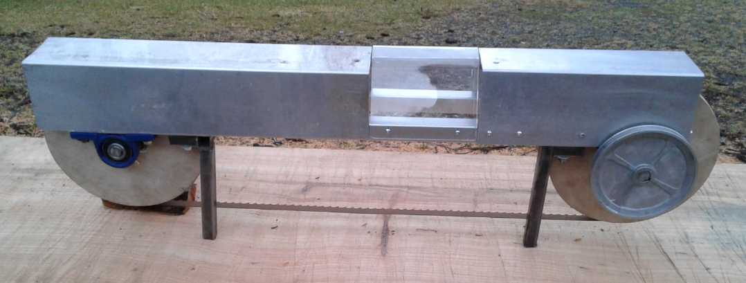
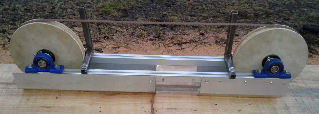
"Carmichael
Mill" - a Portable Bandsaw "Alaska Mill"
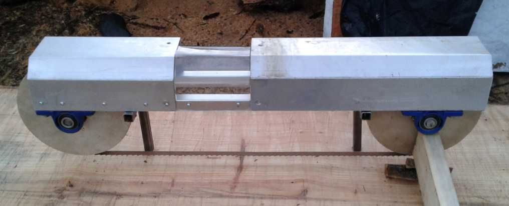
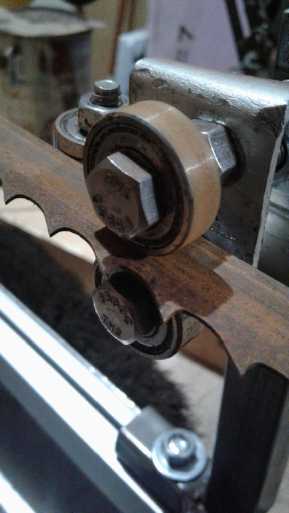
A Better Cutting Band?: Meat cutting bandsaw band has less bone
Meat Cutting Bandsaw, exit guides detail
The wheels on this saw had a ridge on the
back edge, so no rear guides were required.
 For
some strange reason I had bought a meat cutting
bandsaw a couple of years ago. It was just some hunch that I would need
it, when I had no earthly reason at the time. I hadn't even thought of
it when I wanted bandsaw parts for the mill. It was still stashed in
the shipping container. When I did think of it, I remembered that meat
cutting bands seemed to be even thinner than regular wood cutting
bands, and seemed to be made of stainless steel (or something) instead
of rust covered blue steel. On the 3rd I measured the bands to verify
this impression. Wood bandsaw band: .9 mm thick (1+ mm if rusty). Meat
bandsaw band: .5 mm. What about the actual cutting thickness, with the
set
of the teeth? It was harder to measure that, but the wood saw seemed to
be around 1.2 mm and the meat one about .75 mm. It would have less
kerf, make less sawdust. And the clearance behind the cut? Wood saw:
1.2 mm - .9 mm = .3 mm; meat saw: .75 mm - .5 mm = .25mm. So, the meat
saw had almost as much clearance as the wood saw. Should it not cut
wood just as well?
For
some strange reason I had bought a meat cutting
bandsaw a couple of years ago. It was just some hunch that I would need
it, when I had no earthly reason at the time. I hadn't even thought of
it when I wanted bandsaw parts for the mill. It was still stashed in
the shipping container. When I did think of it, I remembered that meat
cutting bands seemed to be even thinner than regular wood cutting
bands, and seemed to be made of stainless steel (or something) instead
of rust covered blue steel. On the 3rd I measured the bands to verify
this impression. Wood bandsaw band: .9 mm thick (1+ mm if rusty). Meat
bandsaw band: .5 mm. What about the actual cutting thickness, with the
set
of the teeth? It was harder to measure that, but the wood saw seemed to
be around 1.2 mm and the meat one about .75 mm. It would have less
kerf, make less sawdust. And the clearance behind the cut? Wood saw:
1.2 mm - .9 mm = .3 mm; meat saw: .75 mm - .5 mm = .25mm. So, the meat
saw had almost as much clearance as the wood saw. Should it not cut
wood just as well?
All else being equal, the meat blade should use not a lot
over half the power to mill wood. That depended on it cutting straight
and not jamming, and on the teeth staying sharp. The teeth just might
dull faster, but the fastest dullener is heat, and the mill will have
water drip cooling on whatever band it's using. Something not equal was
that the teeth were finer, 3 per inch instead of 2.
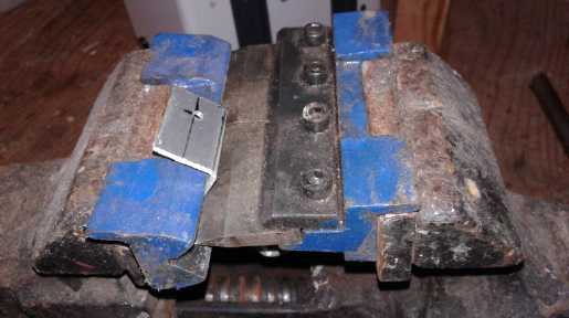
I looked at the band guide blocks in the meat saw. They
were somewhat different than in the wood saw. The lower ones seemed to
be made to deflect meat and bone bits away to keep the band from
clogging up - just as I had been thinking about for bark and chips. And
they were staggered, the left and right ones at different points
instead of across from each other so if a wedge of bone did get in, it
could push past without jamming the blade. That seemed like a fine
improvement too.
The aluminum wheels were also different from wood bandsaw
wheels. They were small (just ~8.5"), flat rimmed with no tires, with
in-line grooves where the blade ran, and had a ridge on the back to
stop the band from riding off when cutting, instead of rear blocks near
but between the wheels. (That just might run a little more freely, less
heat - or keep the band running more straight?)
The thin band was a very exciting find. Using less power
to cut should be like having the under 2 HP motor perform as if it was
3
HP - without any added weight or using any more electricity. It should
make the plug-in electric model that much more practical and faster
cutting. And the thin blade will obviously bend freely around "big" 10"
wheels.
It seemed well worth trying, and even having on hand for
when the mill was ready. The band in my meat saw was way shorter than
the 93" wood band. On this mill I can move a pulley in to accommodate
short bands, but it wouldn't have much cutting width. It would probably
cut boards from a 6" wide cant, but not much more. (With the small
wheels, the meat bandsaw had virtually a 10" vertical cutting capacity
even with the short band.) But it's the wide cuts where more power
(easier cutting) would be the most helpful.
On line I found Dimar Canada (manuacturer of many saw
blades and bands) has them with 3 or 4 teeth per inch ("TPI") and will
cut them to any length. There being no shop tool dealers around here I
asked about mail ordering two, 93" long, 3 TPI. The next day they sent
me a link to a list of dealers in BC that do mail order. I went to
Skukum Tools in Victoria, since I had bought saw blades there when I
lived in Victoria. I thought they would be costly, but they were about
the same price as wood bands. I ordered three, 93" x 3/4" x 3 TPI,
.022" thick (.56mm).
Building, continued
Still on the 4th I went into town and got a bunch of nuts
and bolts. Amazing how you can have a big selection and still not have
the ones you need! With the angle grinder & zip disk I cut up two
pieces of previously welded up 3/4" square steel bracket assemblies to
use as arms to hold the band guide blocks. Once cut they had the 3D-"L"
shape I wanted without doing any welding myself. I wire brushed the
rust off (bench grinder with wire brush wheel) and drilled mounting
holes, and fitted them on.
Next I looked for a way to mount the Ryobi skill saw. At
first I thought the best thing would be two "U" bars (more like "["),
3" tall by about 1" top and bottom. Bolted to the main bars the tops
would be above the wheel about 1/2", and the four corners of the saw's
bottom plate could be bolted along the top. Checking more closely, for
the saw pulley to line up with the mill's pulley, it didn't fit so
neatly over the two bars, but was off the front one entirely and
hanging a good way over behind the rear one. It seemed to defy finding
a simple, sturdy solution. Then I realized that a 4" x 5.5" x 4" upside
down "U" could form a cover over the whole thing, and that the saw
could be
bolted to. I also realized that meant the cover would have to be
unbolted to get cutting bands on and off. Oh well!
The Ryobi would be in a very awkward position to hold its
switch on while cutting. I had intended to tape the switch "ON", and I
looked on line for a pistol grip switch to put in "upstream". It wasn't
proceeding very well. I could find trigger switches, but they still
needed to be mounted in something. Then I figured if that was the case,
I might as well take the one out of the Ryobi and extend its wires.
Then re-mount it in some sort of pistol grip, perhaps made on the 3D
printer.
These things now had good plans to be worked out and I
retired for the night happy with the progress.
The 5th started out well enough, as I figured (a) that I
should use roller bearings instead of blocks for all 6 surfaces and
then (b) how to mount at least 4 of them. I picked out bearings that
would go on a 1/4" bolt as a shaft. But I only had 3 and I needed 6. I
went into town and at the NAPA store, which had told me they had them,
the clerk found one the same. I said I would take 10 and he said they
only had the one, and it was 55$. I should have got the bearing number
off him. I went on line to Princess Auto, but the ball bearings were
mixed in with all the other bearings and bushings in an apparently
random order. Every one that said "ball bearing" used the same picture,
with no info about the size or anything. With nothing to go on in
random order amongst about 270 bearings and bushings, I never did find
any close to what I wanted. Chinese stores didn't seem to have any.
(They're probably all made there anyway!) That seemed to leave VXB
bearings in the USA, which would mean extra expenses. I finally gave up
for now and picked some other less than ideal bearings that I already
had. By then it was getting late.
On the 6th I made a 12" x 14" piece of aluminum, bent in 3
places to go over the top to mount the Ryobi saw/motor on. It also
doubles as the guard covering 1/3 of the top of the band. Then, finding
a piece of pipe just the right diameter, that the motor shaft needed to
have around it behind and to support the pulley (the original blade
support being unsuitable), I got the small V-belt pulley properly
mounted on the motor.
Then I thought I'd do something simple and make a guard to
go the rest of the way across the top of the mill. When I got the sheet
metal bender, I'd been tripping over two pieces of acryllic plastic
that Tom had brought me from the dump, saying "you can always use
pieces of plexiglass." As I was cursing them and wishing he'd taken
them somewhere else besides my shop floor, I noted one of them was
folded at 90 degrees, and then it occurred to me it might after all
solve a problem. I wanted the user to be able to see the water drip
and know if it had run out of water while sawing. A guard of clear
plastic would do that. I found a piece of 3/16" lexan that might be big
enough to cover the rest of the mill if it was heated and bent to the
right shape. Lexan is tough and won't crack or shatter if it's hit by
flying bits flung off the band.
No, it wasn't good enough just to bend up some sheet
metal and make the guard. That would have been too simple! I had to try
another new thing, again
something I'd never done before - make folds in clear lexan plastic! I
decided to try out a 6" wide piece first to see how it would go. I
don't know how it's usually done except that you use heat. I put the
lexan in a small "angle irons" sheet metal bender with a piece of paper
above and below to keep the heat from being immediately lost into the
metal (oh, and to avoid scratches). Then I got out the hot air gun and
gently pried up the lever on the bender as I played the gun back and
forth to heat the plastic. After a while and then very gradually it
bent up. Three more bends and quite a while later I had the shaped 6"
piece, and it looked quite good for a first try except a couple of
places I guess I'd overheated had bubbled. I decided that I didn't want
to try doing a much wider piece than that with my technique. 26" to do
the whole rest of the mill in one piece was out. So, still wanting a
clear view place, I made some screw holes and mounted it on the mill.
I had hoped to be able to change the band without taking
anything apart, but the piece for mounting the motor on had to be
sturdy and held on both sides, and I wouldn't trust the plastic to be
mounted on only one side so it got screws on both sides too.
Originally I was just going to have a guard extend past
the band and bend down. But conceivably, one could carelessly grab the
guard to lift the saw and get their fingers into where the band was. So
I decided just to continue the same on the other half, fully covering
the entire top of the saw. These three covers all have to be removed to
change bands.
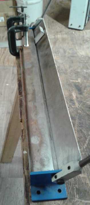
I took pictures outside before the light
faded too much and put in the last screws later. At this point the saw
weighed 22 pounds (10 Kg). That seemed to be about on target for 35-40
complete.
Operator's view
 Log's view.
 Upside down.
 8th: I got the band guides
done on one end. It was a
lot of fiddly adjusting, filing and bending to get all three bearings
in line and straight. And when the whole piece is moved left or right
to adjust the cut width, it will have to be carefully set to the same
angle as it was at when I set it up at the end for the widest cut. If
the band doesn't go into the wood straight and level, it will try to
cut upward or downward and the mill won't work.
8th: I got the band guides
done on one end. It was a
lot of fiddly adjusting, filing and bending to get all three bearings
in line and straight. And when the whole piece is moved left or right
to adjust the cut width, it will have to be carefully set to the same
angle as it was at when I set it up at the end for the widest cut. If
the band doesn't go into the wood straight and level, it will try to
cut upward or downward and the mill won't work.
I started looking to see how the other end might be done
better to make it easier. The other end also needed to have the end
guide "ski" welded on. It sits below the band. The moving band will
pull the saw in that direction until it hits the end guide - or other
parts if there wasn't one. The "ski" bent front gets the mill smoothly
past bumps in the log or wood.
15th: I took the bearings off the leading side, and
and fitted made the pieces with them on the exit side.
I also got a
plastic jar for a cooling water container. Well, with a clear plastic
jar the amount of water left is clearly visible, so the clear plastic
view port to see the water spraying on the band was probably redundant.
But maybe not: it might be seen whether the water is
enough, too little or more than necessary, so the nozzle size can be
optimized. And of course it's still how to see if the jet has become
clogged, which having water in the jar won't indicate.
16th: The ferry came in in the morning for the first time in several
days and I went to the post office late in the afternoon hoping my
parts had come in, especially the bearings. But there was so much mail
and so many parcels the post office hadn't been able to sort it all
yet. Come back Monday! I only got the new, thinner "meat cutting"
bandsaw bands. I put one on the next evening. It seemed to run smoother
than the thicker, rusty "wood cutting" band, and I adjusted the
bearings it did have for the new thickness. I went back before closing
time on Monday (18th) and they still hadn't finished sorting Friday's
mail! This time I got nothing at all.
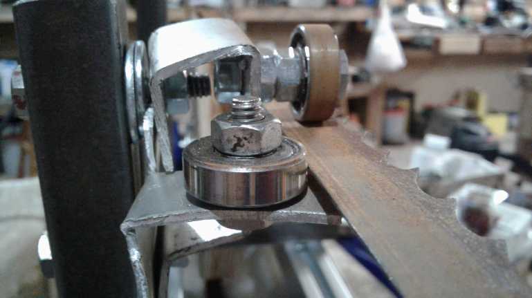 While two rollers clamp the band and keep it
from twisting,
While two rollers clamp the band and keep it
from twisting,
a third behind it keeps it from coming off the wheel
when wood being cut is pressing against the band.
There is one such assembly to the left of the cut and one to the right.
Home Sheet Metal Tools
Some may not realize that for cutting aluminum a regular
electric wood saw works pretty well. Even my bandsaw with coarse teeth
(3 TPI) does well. Finer teeth are better. If it won't fit in that, I
use my radial arm saw. Cut slowly and wear eye protection as well as
ear. So far I haven't had to resort to a skill saw, and I'm not sure
I'd want to.
Steel is tougher. There are metal cutting jigsaw blades
for steel. For sheet metal, use one with fine teeth; coarse teeth are
for thicker plate. Cut slowly and put on oil or water to keep the blade
cool. But for steel I usually gravitate to using a zip disk on an angle
grinder.
 From schools
and shops where I've worked, I was originally
familiar with heavy floor standing sheet metal breaks to bend/fold
sheet metal. At best these are several hundred dollars and they go up
into thousands. And they take up valuable floor space.
From schools
and shops where I've worked, I was originally
familiar with heavy floor standing sheet metal breaks to bend/fold
sheet metal. At best these are several hundred dollars and they go up
into thousands. And they take up valuable floor space.
There are also benders that have a "V" slot and a bar that
pushes the metal into the "V". I've found these only seem to work on
the lightest of sheets - maybe okay for miniature furnace ducts or
something, but not for chassis thickness material. There are some
really small 2-piece ones that fit in a vise (eg, 4" wide). It seems
awfully hard to crank the handle on the vise to bend a small piece.
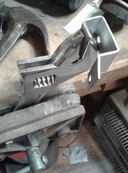 A rather
useful technique I've found for bending metal in
some situations, even pretty thick stuff, is to use a large crescent
wrench - maybe even 2 of them and sometimes a hammer and a vise. The
piece can be put in the jaw of the wrench, which is then tightened on
it. Sometimes a second wrench is needed to twist the first one, since
the handle is pointed in the wrong direction to get good leverage.
A rather
useful technique I've found for bending metal in
some situations, even pretty thick stuff, is to use a large crescent
wrench - maybe even 2 of them and sometimes a hammer and a vise. The
piece can be put in the jaw of the wrench, which is then tightened on
it. Sometimes a second wrench is needed to twist the first one, since
the handle is pointed in the wrong direction to get good leverage.
 But to really do typical sheet metal folding at
home, the
best economical choice is what I call an "angle irons" type, which can
easily be picked up and carried. It consists of two long, heavy "angle
iron" pieces, with hinges and handles at the ends, and a loose flat
bar. The only brand I've seen is "Magnum". They come in 18" and 30"
sizes. (Now I see a 40 inch "Power Fist" one in a Princess Auto flyer.
Each size is heavier built and twice the price of the next smaller
model: ~ 50$, 100$, 200$.)
But to really do typical sheet metal folding at
home, the
best economical choice is what I call an "angle irons" type, which can
easily be picked up and carried. It consists of two long, heavy "angle
iron" pieces, with hinges and handles at the ends, and a loose flat
bar. The only brand I've seen is "Magnum". They come in 18" and 30"
sizes. (Now I see a 40 inch "Power Fist" one in a Princess Auto flyer.
Each size is heavier built and twice the price of the next smaller
model: ~ 50$, 100$, 200$.)
At a glance they seem to be missing some pieces. The trick
is that you supply your own C-clamps to hold down the clamping bar with
the metal to be bent under it. (In order that it not occupy bench space
except when I need it, I also C-clamp the unit to the bench instead of
bolting it on - as I do with several tools.) Leave room behind the fold
point for the thickness of the material, and do the C-clamps up plenty
tight, or they'll slip.
The 30" break did my rather heavy aluminum covers, one of
which was 19" long, without much complaint. (Having done no chassis
making since I bought it, it is in fact the first time I've used the
larger one and I was pleasantly surprised. I think I would recommend it
over the 18" one for all but quite light work, even if the pieces won't
exceed 18".) If the middle area doesn't bend quite as far the the end
near the handle (slight flex in the "angle irons"), it is often
possible to reposition the work at the other end and the other handle -
or - use a big crescent wrench as an extra handle around the middle
where the break flexed most. To do multiple direction chassis folds,
use scraps of steel plate to make your own shorter clamping bars. With
some ingenuity, it's as versatile as the heavy, expensive breaks if not
more so. I made my aluminum motor controller chassies with one.
Motors & Duty Cycle
Someone mentioned that a skill saw motor was probably only
rated to run for short bursts, not for long periods as it will be when
milling. I had thought of that too but I cast it aside for the moment
and will see what happens when I start using the mill. OTOH it's also
probably not very efficient and for that reason too I've also been
casting around for other choices. I may try out the 12 amp motor from
my electric lawnmower. On the 7th I sent a message to "Transmag.com"
who make various BLDC motors that they say are more efficient and
lightweight than other types to see if they would recommend one of
theirs. I
suppose I could use one of my own "Electric Caik" motors, but it runs
on 24 volts, and I still have to figure out how to keep it from
gradually overheating. And I don't want to divert into making another
motor and controller at the moment. (But it might be a good option for
doing any milling necessary in the bush where there's no plug-ins, to
break down logs into movable pieces.)
Drive Belts
I thought of using a link-belt, as they are said to be
more efficient than regular V-belts. They are made up of short plastic
"links" that can be put together (and taken apart again) to make any
desired length of belt. There are two or three different belt widths.
Then I remembered that long ago I had tried one on my upright bandsaw.
It would slip when the going got tough and I had to replace it. The
going will always be tough on a mill.
Then I remembered the belts for variable pulleys, with the
"notches" in them. I dug them out and checked. Sure enough, they would
bend around a small arc much more easily than a regular belt. And I was
using quite a small pulley on the saw motor. Doubtless they were much
superior to the regular V-belts. But they were both too short. There's
yet another web search I'll have to do, and then I'll order one the
right length. Maybe even a small selection of them, and one for my
upright bandsaw. Considering how stiff regular V-belts are and how much
power they must lose, I wonder why they aren't all made with the
notches.
Power Supply:
Photos Simplify Repair. (But is it Worth Repairing?)
On the evening of the 14th I finally replaced the main
filter
capacitor in my "Circuit Test" 0-30 V, 0-10 A lab power supply. Circuit
Test used a 50 volt capacitor
that ran at 52 volts. In fact, there were a number of marginally rated
parts. But capacitors go bad, and from this low rating and the
symptoms, replacing it seemed like the best bet to fix the supply. I
got a new 22000 uF,
100 V capacitor a month ago, but it seemed like a dirty trick. The
pricey (22$?) part had screw terminals but came with no screws or tabs
to connect, and no clamp to hold it down. I had to go out and buy
#10-32 x 1/2" screws (I had lots of #10-24s) and a hose clamp. To
install it I
spent time bending some bits of aluminum to make tabs to hold down the
hose clamp and make it a capacitor clamp, and some copper tabs to
solder the wires to. Yetch! The rest was unsoldering and removing the
old capacitor, mounting and soldering in the new one, and then putting
all the wires back in, testing, and putting the case back together.
One thing I note simplifies electronics (and surely
mechanical)
repairs these days is the digital camera (AKA cell phone, tablet, etc).
When one had a complex device with a bunch of parts and wires to
disassemble, it used to be necessary or at least prudent to write down
where the nuts, bolts and pieces went and note the color and connection
of each wire before disassembly, in order that it might be reassembled
without mistakes. Today a picture taken with a digital camera shows it
all in its original condition. Words take time to jot down and can
later be
confusing; the picture is quick to take and unambiguous. There were two
white wires with black boots. I noticed in the picture one boot had a
bit of white writing on it. I had them backwards, and might not have
caught the mistake without that.
That seemed to fix it. The loud
buzzing
followed by destructive behavior didn't happen again. But the
supply was getting increasingly quirky. For some time the voltmeter
hadn't been reading. I hardly noticed because I had already connected a
little
2-wire self-powered DVM for more precise readings. But it also
did funny
things, putting out "random" high voltages until it was turned up to
about 2.5 volts, with the higher voltage relays chattering on and off.
Well, who would want less than 3 volts anyway? Now it wouldn't put out
above 2 amps even on the 10
amp range. And a wire had burned out a trace, and if reconnected it
made some sort of short - no
voltage could be had, just current limiting. I replaced a shorted diode
and it made no
difference. I couldn't for the life of me see how it could have worked
at all with that diode shorted. By then I had several hours into it. It
would
likely take several more to restore it completely. It seemed to work
well enough for 2 amps or less, but the real
solution, apparently, was to spend several hundred dollars and buy a
nice, tame,
predictable new power supply with digital displays. Sigh! (Next problem
was choosing. I found so many on line on the 16th that I didn't pick
out one that I liked and wanted to pay for, when most of them were over
1000$.)
The next day (17th) I decided I should get a small, rather
cheap one (200$) that I had seen, specifically for charging single
battery cells for those experiments. All along I've been using a cheap
power adapter that puts out a varying, unregulated voltage and current,
through a resistor that sets the current to the cell. And measuring the
voltage across the resistor to see what current is flowing. Suddenly
that seems senseless when I could so easily be using a regulated supply
to put out a constant current or voltage. But I was too busy to order
it.
On the 31st, while still in Victoria over Christmas, I
found and ordered a 16 volt, 5 amp supply from Digikey for just 130$.
(I knew it wouldn't be delivered until after new year's when I was home
again. It had not in fact arrived by January 11th - ouch!)
I figured that would do fine for battery experiments. It
would display current or voltage (not both at once), but it had an
indication
of voltage or current regulation. If the voltage stayed where it was
set, a known value, I only needed to see the current the rest of the
time.
If I need 30 volts at 10 amps I can either try to figure
out the problem or order a more costly supply. Or just use batteries.
Electricity
Generation
Nanocrystalline
titanium
dioxide
borosilicate glaze:
"pebbly concrete" glass surface for solar panels
Some years back I created a nanocrystalline titanium dioxide
borosilicate glaze - highly transmissive glass with a very high
refractive index. The idea is to grind it into a frit (glass powder),
sprinkle it onto a small piece of glass and heat the glass in the kiln,
partly melting the frit into it to make a tiny size "pebbly concrete"
glass front surface for a solar panel. This should bend light striking
from shallow angles into the glass to be absorbed by the solar cells
behind the glass, instead of reflecting it off, increasing collection
at low sun angles (increasing the hour of daily collection), and
collection of scattered sky light (especially on cloudy days) by a very
significant percentage. Conceivably each panel might make up to 35%
more watt-hours per day.
When I was originally making the glaze, I didn't realize
one could buy solar cells, and it seemed perhaps problematic to try and
test it. I let the project drop. But I still have a couple of pieces of
the glaze (formula #9) ready to try out.
Before moving here I ordered a pack of small solar cells,
each 20 x 40 mm. I finally opened it and discovered I should have
ordered the thin metal strips to connect the cells together and to an
external wires with, because there's really no other practical way to
connect them. Now those are on order and should arrive some day.
The wafers are very thin, and I also discovered that they
are very brittle. I accidentally snapped one in half with just a little
finger pressure. I don't know how 'flexible' solar panels are made and
hang together!
A couple of
VHE Ray Energy Notes
Someone told me that some young kid has succeeded in
getting 'free energy' and that there is a video of it on Youtube. He
will not patent his device. I have yet to find the video.
I'm suspecting that it's easier to do than Steven Mark was
making it out to be because of the wrongly configured MOS gate driver
circuit used by several experimenters about the time his e-mail
compilation came out. I suspect it was his circuit, and that would
explain the difficulties he had controlling his toroidal power units.
But somehow I seem to have been diverted once again from working on
this seemingly important project by projects of more immediate value.
It is frustrating to have so many exciting potential developments
almost at one's fingertips and yet be able to attend to so little in
any given month.
Electricity
Storage
Another round
with Nickel-Nickel
Battery Lab
On the 10th, waiting for parts to continue the mill, I
decided to try setting up my battery lab in the laundry room. It was
really too small but had a vexingly small ("bathroom washbasin") sink,
a ("table height") work counter and some cupboards. An exhaust fan. One
small space with leg room where you could sit at the counter. Not much
else. The counter was vexatious because the cupboards were right above
it to hit your head on when you leaned over it. If not the cupboards,
then their doors.
First I had to empty the cupboards. They had a lot of crap
that seemed to be related to washing clothes and cleaning up. (Most of
it I must have put there myself, too!) It wasn't enough. Before dark I
brought in all the boxes related to battery making and chemistry. They
pretty much covered the small floor and I had to step over and between
them to get by. Apparently I was going to have to keep a lot of
whatever I wasn't immediately using stashed away somewhere else. And
from the condensation on the boxes in the shipping container, that
somewhere would have to be the shelves in the shop.
Chemistry
I decided to give up on the nickel-air idea
for the moment, since the last efforts (as best I could recall them)
hadn't
gone very well. The Nickel-manganese cells had seemed to work except
for the
self discharge from the positive electrode. Nickel-nickel promised
better performance, tho at a much lower voltage, and I decided
to pursue that chemistry again. That took me back to March 2016 and TE
News #98 - it's been a while!
Electrolyte
On checking Wikipedia "solubility table", it turned out
that nickel sulfate is soluble in water - just less so than nickel
chloride. Also manganese chloride and sulfate are soluble. That didn't
stop my Ni-Mn cells in KCl from working... at least not for a while.
But they did fail eventually. I belatedly wonder why I just stuck
blithely with KCl and did no exploring of electrolytes for so long.
I made a little
table of relevent solubilities in water at 20°c from
the Wikipedia table. Copper is relevent because I used cupro-nickel
(70%:30%) for the negative current collector sheets.
Solubility,
grams/100ml
|
Oxide or
Hydroxide
|
Chloride
|
Sulfate
|
Oxalate
(C2O4--)
|
Nickel
|
.013
|
67
|
45
|
.0012
|
Copper (I)/II
|
.0000
|
(.0099)/73
|
32
|
.0000
|
Manganese
|
.0003
|
74
|
63
|
.028
|
Three more that may be of interest for electrolytes are oxalic acid,
13.3 g/100cc at 20°C, rising rapidly with temperature and dropping
below 5 at 0°, potassium hydrogen oxalate, 2.5 at 25°, and
potassium oxalate, 36 at 20° and rising somewhat with temperature.
If solubility indicates that an electrode won't work, I don't
understand why Ni-Mn should have
worked, apparently fine, in potassium chloride. Of course, all the
cells did eventually fail, in a month or less. Perhaps they were
deteriorating with every charge-discharge cycle. After all, MnO2-Zn
cells in ammonium chloride work fine - once. They can recharge once or
twice, but losing much capacity and soon getting a hole through the
zinc outer shell. Solubility of so many things in chlorides would
probably
explain most
everything else. It certainly explains the liking of battery makers for
alkaline cells. Oxalate, then might present a previously unexplored
(if not unnoticed) opportunity.
What were the potential forms of oxalate? Obviously there's oxalic
acid, H2C2O4. What about potassium oxalate? That would be K2C2O4. That
didn't even seem to exist on Wikipedia. Then in between there's
potassium hydrogen oxalate or "hydrogen bioxalate", KHC2O4. It was
soluble if only a little and was
said to have uses for bleaching, and some medical use. (All
these forms are poisonous.) Calcium oxalate is apparently nearly
insoluble - not a good choice! (It's the main material of kidney stones
- ugh!)
I decided to try oxalic acid as the electrolyte.
It
seemed to work for a nickel-zinc test cell long ago, and potassium
chloride didn't seem to work at all with a nickel negative side. If
that doesn't work well, I can make the potassium-hydrogen oxalate by
adding KOH to the acid. The tiny plastic bottle I had from a kid's chem
set wasn't going to go far, so I got on line and ordered 500 g from
acpchem.com .
To sum up: neither nickel metal, nickel oxide nor nickel
oxalate are soluble, and the same for copper and manganese. I think it
would be pretty safe to presume nickel manganates and nickel
oxyhydroxide are likewise insoluble. Thus neither electrode should
deteriorate through dissolving, at any state of charge or during charge
or discharge. It's the acid of choice since all these metals or their
compounds would dissolve in most acids. So, instead of "lead-lead" in
sulfuric acid, it would be "nickel-nickel" in oxalic acid. The
advantage: the atomic weight of nickel is 59 where lead is 207. It's
almost 4 times lighter, so more atoms and more amp-hours per gram. A
nickel-manganate positive would further improve this over pure nickel
compounds - if it worked in the acid.
I hoped I was on more stable ground with these
observations
and the choice than with many of my previous battery ideas.
Building a Cell
Just for a test cell I found a shallow 4" x 6" flat tray
(I made some long ago for the first cells) and I cut a piece of
cupro-nickel to fit with a tab sticking out one end. I sanded it to
roughen the surface. Then I poured some ferric chloride into the tray
and etched it for one minute to further roughen it on a crystal/atomic
scale. Acidic FeCl3 dissolves out the copper faster than the nickel,
leaving a fractally rough, more nickel rich surface at the micro and
nano scale. At this point all I wanted was to see if it worked, if it
would hold a specific voltage and supply current, however briefly. So I
didn't do nickel foam or nickel flakes to really add capacity to the
mix.
Next was a sheet of watercolor paper to cover that, and
then... another sheet of etched cupro-nickel with a tab in the opposite
corner. I figured I'd keep it simple. If I charged it, nothing would
happen to the negative (hydrogen could bubble off from the water), and
the positive would oxidize, and some cell voltage would be found. On
top of that should be a cover. Later!
In mixing the acid I noted that it was soluble to about
23g per 100 ml. Not super soluble, but plenty for a battery electrolyte
I trust.
Expectations: The Reactions
What would the reactions be? The negative side seems
likely to have a half reaction similar to lead-acid:
[charged <==>
discharged]
Pb + H2SO4 <==> PbSO4 + 2 H+ + 2 e- (-.3 V)
Ni + H2(C2O4) <==> Ni(C2O4) + 2 H+ + 2 e- (-.4 V ...?)
The positive side is hazier to me. In alkaline solution
the nickel goes from valence 2 as Ni(OH)2 to valence 3 as NiO(OH). Lead
goes from valence 2 as PbSO4 and becomes PbO2, valence 4. Nickel won't
go to valence 4; we need 3. And a hydroxide seems unlikely in acid. But
NiO(C2O4) would be valence 2 or 4. What oxidized compound could give it
a valence of 3, unless it's Ni2(?)3 ? How about:
O-Ni-(C2O4)-Ni-O ? or else (C2O4)-Ni-O-Ni(C2O4) ?
If that isn't bad enough, it'll get much more complicated with nickel
manganates.
PbO2 + 2 e- + H2SO4 <==> PbSO4 + H2O (+1.7 V)
Ni2O3 + 2e- + 2 H2(C2O4) <==> 2 Ni(C2O4) + 2 H2O
Well, enough of that... at least the last one can't be right.
Testing & Observations
When I was ready I added the acid. It seemed to me the top
surface of the top sheet took on a bit of a purple tint. I wasn't
expecting anything to happen before trying to charge the cell.
Regardless I put the cell on to charge. Perhaps nothing
was soluble, but that didn't seem to stop a purple powder from forming
and drifting around in the otherwise clear electrolyte. Perhaps nickel
or copper oxide or oxalate didn't dissolve, but seemingly it did flake
off the sheet of metal and precipitate out as it formed instead of
becoming the surface
layer of that metal. And what did the color indicate? If there had been
manganese in the mix I'd have been sure it was permanganate. (but
permanganate would have tinted the liquid.)
If it was just forming on the positive electrode it might
be redeemed by making it (as planned for later) a compacted powder in
conductive carbon black with a graphite (oxide) current collector. If
it was forming on both electrodes, it seemed like a show stopper, since
nickel sheet was the intended final form of negative.
The voltage seemed to want to be around 1-1/2 volts on
20-40 mA charge, but decayed rapidly when the charge was stopped. If
shorted the cell supplied around 50 mA. I stopped the charge before
retiring since nothing useful seemed to be happening.
The next day (13th) I took
out the electrodes and looked at them. Both electrode sheets had a
mainly
coppery color, which I took to indicate that the nickel was reacting
away and becoming the purple powder, while the copper was inert. The
solubility table was for compounds, not metals. Nothing was said about
nickel spontaneously turning into nickel oxalate. With the low reaction
voltage of nickel and its noted corrosion resistance I certainly hadn't
expected the negative metal electrode to react during charge or
sitting, only during discharge. Later I noted on Wikipedia that oxalate
may be "a bidentate chelating ligand" and "many metal ions form an
insoluble precipitate with oxalate." That still didn't tell me that the
acid would spontaneously react with solid metal.
The pH of the acid solution (no surprise) was 1
according to my test strips.
Examining it again in the evening, the purple had dried
mostly to a turquoise, and there was some black. Those at least were
the color of nickel hydroxide (valence II) and nickel oxyhydroxide
(valence III) - and perhaps nickel oxalate compounds of those valences
too - nickel oxalate NiC2O4 and (?)nickel oxalate hydroxide NiC2O4(OH).
Those at least indicated the expected sort of reactions had been taking
place. It may be that the purple was due to combination with the
coppery color of the sheet underneath as seen in the liquid. (If there
had been manganese in the mix I'd surely have thought it was
permanganate. Then again, permanganate should have dissolved and
colored the electrolyte purple.)
There was an interesting statement in Wikipedia [Nickel
Compounds] that nickel oxalate "can be formed into various nanorods and
nanofibres by the use of surfactants." Nanotubes, nanorods and
nanofibres
seem to be the holy grail of battery electrode substance making. That
sounded more promising than the loose powder initially indicated.
 The cell case with paper and the electrodes,
top negative, bottom positive
The cell case with paper and the electrodes,
top negative, bottom positive
On the left: damp, the paper side of each electrode
On the right: Dry, the outside faces of the electrodes
Nickel forms many oxalate complexes with other metals, but
I hadn't used any of the ones listed in Wikipedia. I did note there's a
soluble ion basic to them all, Ni(C2O4)2--,
also
written
(C2O4)2Ni--,
which could conceivably dissolve, but the
electrolyte remained clear, which was a good sign that that probably
wasn't happening. It may in fact be the first time I've had an
electrolyte stay completely clear. There was another interesting oxalic
"double salt":
K2[(C2O4)2Ni.2H2O].4H2O
,
structure
monoclinic,
color
green
;
also known as (ready for
this?:
dipotassium trans-diaquabis(oxalato-O,O)nickelate(II)-water
(1/4) ; or more simply:
potassium bis oxalate nickel(II) tetrahydrate.
I suppose, ignoring the hydration, that it might look something like:
K-(C2O4)-Ni-(C2O4)-K. But what would it do when it oxidizes?
("bis": "a molecule with two complex ligands co-ordinating around a
central atom". The oxalate ion has two ligands. Also, similarly to the K2[...
there's
NA2[... and Li2[... , each with different
hydrations) We see from the formula that there's just hydrogen, oxygen,
carbon (as water & oxalate), nickel, and
potassium. Potassium can easily be added to the acid as potassium
hydroxide. I got the feeling that there might be some sort of key here.
These things bring me back to the idea of compacted powder
electrodes with chelating the
cations, eg in the Sunlight dishsoap (a surfactant with sulfonates), so
they stay put regardless of
the state of charge.
But why would the negative side have reacted at all
without delivering electrons to an external circuit? The top sheet (the
one I could see) seemed to start turning purple as soon as the acid was
added. Nickel and copper were both supposed to be insoluble in oxalic
acid. The zinc electrode in my test cell long ago eventually got a
light whitish coating, but that took a week or more.
Conclusions
How could it work if the metallic nickel was spontaneously
eaten away by the acid, forming a loose precipitate of [presumably]
Ni(C2O4)? Whatever might or might not be done with the positive
electrode, this was a show stopper. However, the non-solubility of the
oxalates and oxides of the metals in question still makes oxalate look
like a promising anion. Potassium hydrogen oxalate is only soluble to
the tune of 2.5 g/100ml, which seems pretty thin for an electrolyte.
Wikipedia didn't have an article on potassium oxalate; the
name redirected to "oxalate". This caused me to dismiss it in my mind
as being something that for some reason probably wasn't stable or
usable for anything. It was therefore a bit of a blank, but now it
seemed to be the obvious thing to check out next.
Next Electrolyte: Potassium Oxalate?
A web search led to various tidbits showing that potassium
oxalate monohydrate seems quite available, not to say common (eg, "25
Kg bag"), and that it is pH 7 to 8.5 when dissolved. It's also much
more soluble (36 g/100 ml) than the acid or the KH(C2O4) version. (I
also thought of sodium oxalate, but it's only 4 g/100 ml soluble.)
One would expect that to make it, I would take the acid
and add twice as much molar weight of potassium hydroxide:
H2(C2O4) + 2 KOH => K2(C2O4) + 2 H2O
(90 g) + 2*(56 g) [=90 g + 112 g]
If I mixed it right, the pH should be 7 to 8.5. One would
think the slightest imbalance would make it either very acid or very
alkaline. But Wikipedia said solutions of KH(C2O4) were alkaline. So it
may be alkaline even if I don't add enough KOH. (Not to be forgotten
it's also quite poisonous and irritating to skin, eyes and mucous
membranes. Wear gloves and face (or at least eye) protection.)
But it gets more complicated when one considers the
electrode reactions. If nickel metal is to turn into Ni(C2O4) during
discharge, that's going to use up oxalate from the solution and leave
excess K2, which will form 2 KOH + 2 H+. If it gets too alkaline nickel
will stop oxidizing. Alternatively if one put in potassium hydrogen
oxalate, the KH(C2O4) should turn another oxalate ion into K2(C2O4) +
H+. At the other electrode, something like Ni(C2O4)OH would lose the
OH- to combine with the H+ and make water. (or what would happen with
nickel manganate?)
Cell with KH(C2O4)?
 Everything seeming too complex to be sure what would
happen, so the thing to do might be to make new electrodes, mix some
KH(C2O4), and try it out. Then I decided to try just sanding the
present electrodes to expose more nickel surface. Then I was using the
wire brush on the grinding wheel for something, and I tried that
instead. It took it
back largely to its nickel color and also left an interesting rough
textured
surface at a fine scale, especially where pressed "too" hard and
locally heating the metal surface up. Perhaps it melted away the
surface copper?
Everything seeming too complex to be sure what would
happen, so the thing to do might be to make new electrodes, mix some
KH(C2O4), and try it out. Then I decided to try just sanding the
present electrodes to expose more nickel surface. Then I was using the
wire brush on the grinding wheel for something, and I tried that
instead. It took it
back largely to its nickel color and also left an interesting rough
textured
surface at a fine scale, especially where pressed "too" hard and
locally heating the metal surface up. Perhaps it melted away the
surface copper?
Positive Electrode Characteristics
I found an experiment on line (m.jes.ecsdl.org/content/161/12/H787.full)
where researchers were trying to
measure the surface area of nickel electrodes. They used oxalate in
alkaline media in this. The graph
seems to indicate that a positive electrode oxidizes
strongly with oxalate where a nickel metal electrode wouldn't just with
KOH (at about +1.4 volts on the graph). These points are also .08 volts
lower voltage than nickel hydroxide in straight KOH. (Since
all my cells have been having a problem with self discharge in the
positive electrode, this slightly lower voltage just might
make a big difference, suggesting that this might be another good
reason to
try oxalate. The voltages shown in the graph are measured against a
"reversable hydrogen electrode" instead of a "standard hydrogen
electrode" and are much higher to the "+" side than the +0.48 volts
usually shown for
nickel [oxy]hydroxide in alkali.
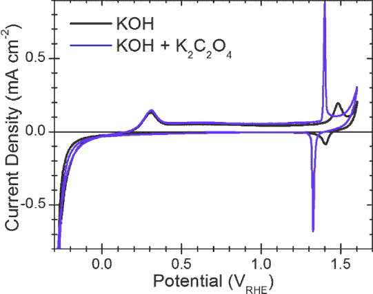
Note that K2C2O4 was used
rather than H2C2O4. It is therefore an alkaline solution. My intent was
to add only enough KOH to convert the H2C2O4 to KHC2O4 or K2C2O4, with
no KOH remaining. But it might be that "best balance" would be more
strongly alkaline. The best ratio of KOH and H2C2O4 used in the
electrolyte might be almost anywhere.
On an interesting note, it
is said that nickel metal at pH
14 uniquely of all metals "will not oxidize". But this seems to be an
oversimplification of
the actual case. The article indicates that a thin hydroxide layer
forms on the surface of the nickel, but it doesn't
come off, preventing deeper oxidation, much the same way as aluminum in
air always has a thin aluminum oxide film on it. With the oxalate it
seems much more oxidation takes place when it hits the reaction
voltage, +1.4 volts.)
The small current bump shown as about +.3 volts of rising
voltage may represent the potential at which this layer starts to form,
with slightly more penetration ongoing until, in oxalate electrolyte,
the rising voltage reaches the main +1.4 volt level of general
conversion to (?)oxalate-hydroxide. The distance between the -.3 volts
and the +1.3 volts would indicate the potential of a nickel-nickel
cell, about 1.6 volts. It might be considered 1.5 or 1.4 volts under
load. Or given the gradual curve, it might be .1 or .2 volts lower.
http://www.TurquoiseEnergy.com
Haida Gwaii, BC Canada