Turquoise
Energy Ltd. News #116
10th Anniversary Issue
covering
January 2018 (Posted February 3rd)
Lawnhill BC Canada
by Craig Carmichael
www.TurquoiseEnergy.com
= www.ElectricCaik.com
= www.ElectricHubcap.com
= www.ElectricWeel.com
Features:
* Carmichael Mill ("bandsaw alaska mill") First Tests!
Month In Brief
(Project Summaries etc.)
- Nissan Leaf (light blue) -
Carmichael Mill ("Bandsaw Alaska Mill") - Motor Development Thoughts -
Electrolytes for Nickel-Nickel (& Air-Nickel?) Batteries
In Passing
(Miscellaneous topics, editorial comments & opinionated rants)
- Beach Plastic & Burning Plastics - Wall Street Woze - Plagues
- Project Reports
-
Electric
Transport - Electric Hubcap Motor Systems
* Caik and ARM Motor Production Thoughts - Development of the new
types
* Experiment: Melting and Molding Scrap Polypropylene
Other "Green"
Electric Equipment Projects
* "Carmichael Mill" AKA "Portable Bandsaw Alaska Mill"
Electricity Generation (no reports)
Electricity Storage - Turquoise Battery
Project (NiMn, NiNi, O2-Ni), etc.
* Electrolyte: Potassium Oxalate?
* Electrolyte Medium: Deep Eutectic Solvent (DES) "Ethaline" -- a salt
that's liquid at room temperature -- instead of water?
* Getting the stuff
* Making the DES
January in Brief
I didn't get TE News #115 - the last one of a decade -
sent out until January 12th. There are around 150 subscribers. On the
14th Google sent me 150 e-mails saying "delivery delayed - will try
again". It had done the same thing to me in November, but then they
were sent. This time came another 150 e-mails on the 16th with the same
message. On the 17th they sent me another 150 e-mails saying "delivery
failed". Not to mention that the newsletter didn't get out, this is the
worst case of spam filling my mail box with junk that I've ever had,
and they came from Google. Couldn't they just say "message rejected",
once, when it was sent, and the actual reason why?
On going to one of the links supplied with each notice to
check out what had happened, it said if I wanted
to send to a large subscription list I should "start a Google group".
Yikes! I
didn't have the stomach for trying again and incurring another 450
"failure" messages for a few days. Then I split it into two groups and
sent the second one after receiving no 'google spam' from the first for
about 3 days. So assuming this one is on time it should be "hard on the
heels" of last month's.
My friend Tom Sawyer and his wife and young son, who came
up to
Haida Gwaii when I moved here, moved back to Victoria in January owing
to circumstances turning averse for them. He was ever there when I
needed a hand. He did a
lot of hard and much needed work here, especially building a large and
excellent post and beam shelter over my travel trailer (with only a
little help from me) for a low cost, with much sleuthing out of low
cost building materials. They will be missed.
Nissan Leaf
On the 21st, the first full day I was in Victoria for
Christmas, I went with my sister in law to look at cars, as she needed
a new one. She had a long daily commute with nowhere to charge at work
(a high school), so using an EV seemed unworkable and she got a Toyota
Prius.
But I started getting the idea again to buy an electric
car myself. Things weren't looking good for Tom to bring any up to
Haida Gwaii to sell so I counted that as "out" (correctly, as it turned
out),
and now I was busy making the bandsaw mill instead of the
"hybridization" of a car.
Someone had a 2014 Leaf on UsedVictoria.com for 14000$. That was a
great price, but it turned
out they had decided not to sell the car. The e-mails took it to boxing
day. That day Kolenberg Motors near
Duncan put about 4 'new' Leafs (lease returns, again from USA) up on
UsedVictoria. The next day I was going to pass by Duncan taking my
mother home to Comox. We stopped in. I test drove a 2015 (the base
model - which seemed really luxurious to me compared to anything I've
driven before!) and bought it for 17000$. (...plus financing, taxes and
registration and 6 months insurance - and delivery to Haida Gwaii by
barge: over 21000$. I'll be paying on 11000$ for 6 years, but at 5%
interest
it's only ~1000$ extra over immediate cash. I saved about 1400$ over
one I almost bought a
few days earlier, and it's a model year newer.) The next day, the 28th,
I realized I had to hurry and
get the car to North Arm Transportation by the following afternoon to
get it on the January barge to Haida Gwaii. The barge wasn't leaving
until January 24th, but Friday, December 29th was the last business day
to deliver it before I flew back myself. Then a month of sitting and
waiting for the car to arrive! That same evening I ordered a 30 amp
J1772 EV charging station from Home Depot, not especially to charge
fast but because
Julian had noted those Leafs normally using 240 volt charging seemed to
have
longer battery life with slower deterioration.
"ETA" of the barge to Masset was January 30th, but owing
to
weather it was delayed until the 31st. (Better late than damaging or
losing my car!)
Tom had ordered and put a deposit on a used 15 amp J1772
EV charging station privately (Craigslist Seattle), but left the seller
my home phone number. When the seller phoned, with Tom having moved and
I having bought the Leaf, I said I would buy it. It arrived in the mail
on the 30th. The 30 amp one from Home Depot hadn't arrived yet and I
e-mailed to ask if I could cancel it. I expect the slower 15 amp
charger will be best for battery longevity.
 The barge duly
arrived on the 31st. The car hadn't been charged so I couldn't drive it
home to Lawnhill. It would take many hours to charge from a 120 V
outlet. I drove to Masset Services and got a lift on a tilt-deck truck.
Another 250$, but for a cause: the driver should be a great fellow to
know. He had been very involved with building an electric tricycle and
a couple of small private hydro power installations, and was definitely
'into' it all on a DIY basis. I showed him my shop and I'll look him up
again when I'm in Masset.
The barge duly
arrived on the 31st. The car hadn't been charged so I couldn't drive it
home to Lawnhill. It would take many hours to charge from a 120 V
outlet. I drove to Masset Services and got a lift on a tilt-deck truck.
Another 250$, but for a cause: the driver should be a great fellow to
know. He had been very involved with building an electric tricycle and
a couple of small private hydro power installations, and was definitely
'into' it all on a DIY basis. I showed him my shop and I'll look him up
again when I'm in Masset.
 Getting the Leaf
doesn't mean I'm not going to install my transmission
in the Miles (or the Echo - or both), but it does lower it from almost
the top of the project list down a couple of notches. Obviously if such
cars had been available in 2008 when I started all this, doubtless I
never would have started. At least not in the same way with the same
projects.
Getting the Leaf
doesn't mean I'm not going to install my transmission
in the Miles (or the Echo - or both), but it does lower it from almost
the top of the project list down a couple of notches. Obviously if such
cars had been available in 2008 when I started all this, doubtless I
never would have started. At least not in the same way with the same
projects.
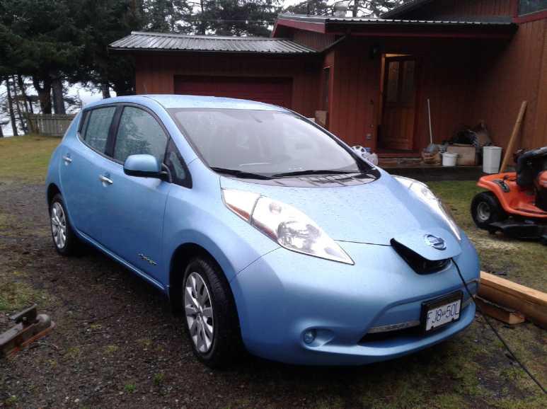
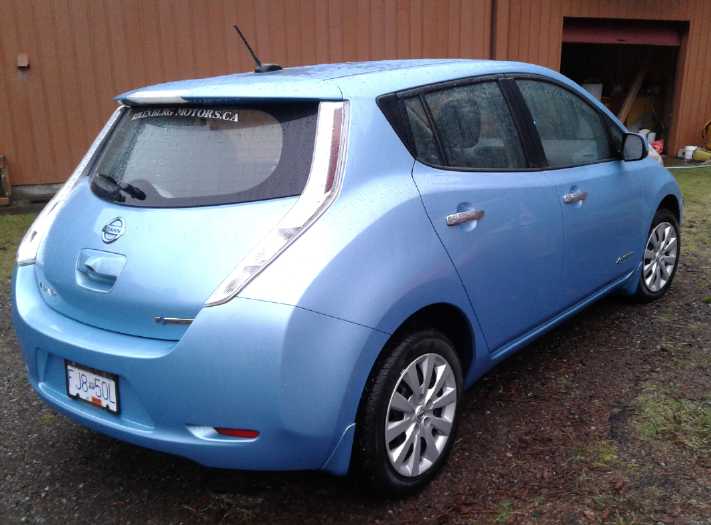
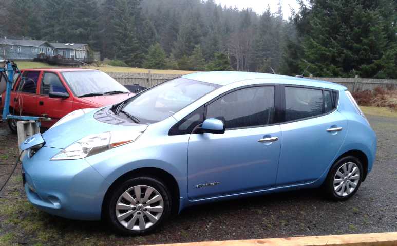 The Nissan Leaf, with the neglected Chevy
Sprint behind it,
The Nissan Leaf, with the neglected Chevy
Sprint behind it,
and the front of the boat trailer.
(Things should be less cluttered when I've cut up the wood blocking
half the driveway with the "Carmichael Mill".)
Carmichael Mill ("Bandsaw Alaska
Mill")
I made sliding
"legs" with "skis" for setting the cutting thickness, then welded a
"skid" onto the side that would pull itself against the log when
cutting. On the 24th I made a handle for the left side and mounted the
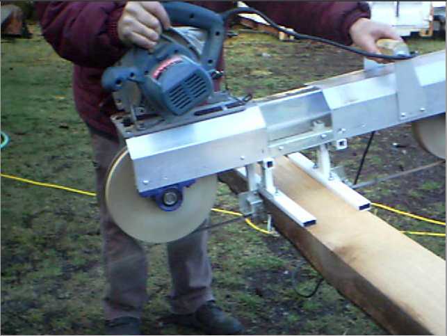
Ryobi Skillsaw on top, at the right above the pulley.
Then I took it out and cut a few inches into a 6" wide
irregular beam that I wanted to make into 2"x6"es. It cut great - Wow!
it was everything I was hoping for. I got out the camcorder and took a
couple of videos. I backed the saw out of the cut (now 30" long) and
the band came out
from the guides. I popped it back in and thought little of it. But I
tried to cut the next day, to see how warm the band got (not very) and
cut the whole board... and everything was out of alignment. (I did
however measure 2 feet cut in 16 seconds, or 7-1/2 feet per minute for
a 6" wide cut in spruce.) An attempt to fix it was only partly
successful. One side cut straight while the saw climbed out of the wood
on the other, raising the left side and cutting a twist shape. I
decided to replace the thick aluminum sheet pieces holding the guides
with thick
aluminum plate to be sure it was 'rock' solid, and to make some sort of
screw adjustment on at least one side. But the weather got too cold for
working outside or out in the shop. So stay tuned next month.
Motor Development Thoughts
As I was thinking about a motor for the mill, I finally
remembered I had made my own "Electric Caik BLDC4:3" motor in 2015, a
novel BLDC configuration. I hope to find out if it's better. It looked
like the best option, except for needing a motor controller that has to
be completed or repaired (ugh!), and it needs to run from a 24 volt
battery instead
of plugging into the wall.
Perhaps still better would be the ARM
reluctance motor with "permanent magnet assist", but here both the
motor and controller need further development.
Either of these would give an opportunity not just to
power
it better, but to further test my motors in serious use,
demonstrate that they work, and to try out and develop different motor
controllers. On a reluctance type motor with its "unipolar"
controllers,
I can try out "permanent magnet assisted" motor coils, which apparently
reduce currents under heavy load and make
batteries last far longer.
To get the band mill going now, I
powered it with the Ryobi 13 amp Skillsaw. I can replace it with
another motor and controller of my own
making when I have a pair working well.
Electrolytes for Nickel-Nickel (& Air-Nickel?)
Batteries
I was waiting for more oxalate to continue with this
project. On the 11th I enquired
about my web order of December 11th for oxalic acid. ACPChem.com seemed
to have no record of it! More helpfully,
they suggested I try a place called westlab.com , which turned out to
be in Aldergrove BC (much closer for shipping) and their prices were
lower. Again it was all automated and a web form said my
order was created successfully. (hmm! Well, apparently this one was,
because the goods arrived.)
Instead of oxalic acid I got potassium oxalate (500g),
which is almost undoubtedly what I would have turned the acid into
anyway. (Forget making KHC2O4.) A moderately alkaline solution with
K2C2O4 (and perhaps
KOH or Ca(OH)2) is most likely to be best. A salt is probably also
easier/cheaper to ship than an acid, which would probably be deemed
"hazardous material".
Also I considered that I still hadn't tried making the
'ethaline' DES (deep eutectic solvent) for electrolyte use. The DES is
a complex ionic liquid organic salt with a higher reaction voltage than
water, so
using it instead of water well might eliminate the self discharge of
the positive electrode that has plagued all my cells virtually from the
beginning.
I now had the vacuum pump and most of the fittings, and the
choline chloride. But I couldn't find the other
ingredient, the ethylene glycol. (Lost in the house move somewhere, I
suppose. Did somebody I know find and pour my pricey, high
purity bottle
into their leaking truck radiator?) So I ordered another litre of that
too.
In going over Leonardo's 2015 instructions for making the
DES,
I discovered that I hadn't read closely enough. The bulky "vacuum
bottle" that I bought for
the vacuum can't be used because the evacuated jar has to be
turned in a rock tumbler for half an hour to mix the ingredients.
Perhaps a regular jar with a small lid? (And before I moved from
Victoria, I
was in "Rockhounds" shop and I had an urge to buy a rock tumbler.
Unfortunately I managed to tell myself that was stupid, that I didn't
want to polish rocks.) Then I checked my vacuum pump. The fittings
looked like air compressor thread fittings, but they weren't quite the
same. Luckily someone had a jar of various fittings and we found some
that fit. (3/8" NPT?) I tried out some plastic tube and found it didn't
collapse
with a vacuum inside, so I didn't have to solder up a copper pipe
assembly. Yay!
 On the morning
of the 30th I decided to try making a small
quantity. I ended up using a beer bottle with a test tube stopper for a
lid. It all worked like a charm, but I had to settle for shaking the
bottle by hand for 1/2 an hour in lieu of the rock tumbler. In the
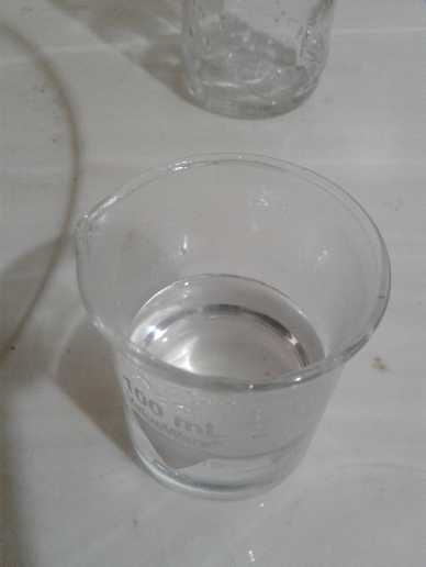
final heating I got the expected clear liquid: 50cc of precious DES!
(There now, that wasn't so hard after all, was it? How long did you put
that off?)
On the morning
of the 30th I decided to try making a small
quantity. I ended up using a beer bottle with a test tube stopper for a
lid. It all worked like a charm, but I had to settle for shaking the
bottle by hand for 1/2 an hour in lieu of the rock tumbler. In the
final heating I got the expected clear liquid: 50cc of precious DES!
(There now, that wasn't so hard after all, was it? How long did you put
that off?)
The Ethaline DES. (Okay, it
doesn't look very exciting!)
In Passing
(Miscellaneous topics, editorial comments & opinionated rants)
Beach Plastic - Burning Plastics
On the 18th I removed 100 pounds of polypropylene ropes
from the beach, one huge one and a few bits and pieces. The next day
after a storm I walked along and saw pieces of plastic all through the
high tide zone from tiny shards to old drink bottles to more old,
frayed rope and
nets (which are usually tangled in logs or half buried in sand and
rocks,
impossible to pull out). I had done some substantial plastic cleanup
before, but it didn't look like it now. Not to mention those piles of
old logs themselves, left over from a century of careless logging. The
next day I took a bag and a hacksaw to cut rope, and came back with
both arms full. And on subsequent days my hands were usually full too.
On the 30th I found a line in the sand: one small or tiny fragment of
plastic after another after another, extending many yards (probably the
morning's high tide line). I spent a while picking each bit up until
I'd had enough.
If a
remote beach like this is so polluted, is there anywhere in the world
that isn't? Plastic in the oceans is said to be an ecological disaster
and now the world's worst pollution problem.
We've been told "Don't burn plastic", but there are many
types of plastic and the neglect of this blanket statement in not
distinguishing between completely clean burning, fair (about like
gasoline in a car), and toxic types contributes to our inability to
deal with the problem. Clean burning types PE, PP
and PETE (which accounts for nearly all of it) go into the woodstove
(unless I save any for potential
remelting and reuse - see under Electric Transport below).
Don't put in too much at once; it can get really hot. Why bloat the
landfills, and why recycle if perhaps more petroleum is burned
transporting and processing the plastic than is contained in the
plastic? A piece burned will never bloat a landfill, sully a beach or
become part of a floating island of plastic in the ocean. The problem
may seem overwhelming, but plastic is made and sold a bit at a time, so
it can and probably should be cleaned up that way too. There's nothing
that will clean up the planet except
cleaning it up!
Wall Street Woze?
I read one headline in a couple of places, "Wall Street is
Desperate for Investors". I didn't bother reading/watching, but
translating the title into English, it would
appear that Wall Street has run out of suckers to relieve of their
savings. And why wouldn't it? Virtually all wealth created in the past
year went to the highest .01% income earners while the lower 50% got
exactly 0% of it. If the few billionaires and trillionaires aren't
buying perhaps fraudulent stocks in companies they probably already own
and control anyway, who else is there to buy?
Plagues
Just one news source, "FullSpectrumSurvival" on youtube,
seems to follow the spread of diseases around the globe. There's Ebola,
Black Plague and MERS, but so far the best candidate for causing a
devastating pandemic looks like the ever mutating strains of flu. And
that's being seen this year as I've heard the widespread flu even led
to California hospitals setting up tents for the sick. All that is
needed now to wipe out large percentages of populations everywhere as
has been forecast is for one that is as contagious and more severe.
(There has also been a very nasty cold going around in BC that has
claimed at least one young victim so far.) Next flu season is the
hundredth anniversary of the "great flu" of 1918-19 that killed
millions worldwide. Today the world has four times as many people to
help spread it.
The "in depth reports"
below for
each project. I hope will help anyone who wants to get
into a similar project to glean ideas for how something
might be done, as well as things that might have been tried or thought
of... and often, of how not to do something - why it didn't
work or proved impractical. Sometimes they set out inventive thoughts
almost as they occur - and are the actual organization and elaboration
in
writing of
those thoughts. They are thus something of a diary and are not
extensively proof-read for literary perfection and consistency before
publication. I hope they add to the body of wisdom for other
researchers and developers to help them find more productive paths and
avoid potential pitfalls.
Electric
Transport
Electric
Hubcap/Caik, "BLDC 4:3" & ARM Motor
BLDC 4:3 Types
In connection with the bandsaw mill I started remembering
this configuration, with four rotor magnet poles instead of two per
three stator coils, and that I had such a motor that I made in 2015.
The idea was that it could be run from a unipolar motor controller such
as is used with a switched reluctance motor. (TE News #78-90) However,
it seemed that when there were only like coils energized (all 'north'
or all 'south') instead of equal north and south, torque is much
reduced. The idea of making a non-symmetrical rotor so that two coils
of a single phase could be N-S foundered on the fact that no matter how
the rotor magnets were arranged (unless asymmetrically - unbalanced),
it seemed it would start trying to run backward at half
the points of its rotation unless the coil polarities were reversed,
which defeated the whole idea of having a simpler, more reliable
controller.
The 4:3 configuration should still run well with a regular
BLDC controller, and should be compared in characteristics with the
regular 2:3 configuration to see if one is notably better than the
other. (I meant to test it to make sure it did run well, but didn't get
to it.)
Production Thoughts
The regular Hubcap and Caik BLDC motors run quite well,
and the molded
polypropylene-epoxy composite makes good tough motor bodies. But I
can't help but think the bodies aren't the easiest, fastest or most
uniform parts to make. For production something that rapidly stamps out
a more uniform product would be much better. I noted a while back an
electric lawnmower that had its entire body molded of polypropylene
plastic. Perhaps that would be a good way to go for the motor bodies,
too? Burning some waste PP rope from the beach (it burns much like
propane - polypropylene is after all polymerized cyclopropane) I noted
that it generally melts and flows or drips before it catches fire. What
if it was heated to the point where it flows but doesn't catch fire
(very hot), in an aluminum dish mold of the desired motor part shape?
That's something to try out. And perhaps polyethylene terapthalate
(PETE) that makes fairly rigid plastic bottles and packages might also
be a good stiff body plastic if all those thin-walled packages and
containers will heat and melt together into one chunk.
On the 18th I found a long 1-1/2" diameter rope on the
beach, all wound together with kelp, sticks and logs. I had to cut away
a lot of kelp and hacksaw the rope into three lengths (relatively
equal, as it turned out) to free it, and I dragged it home in three
loads. On weighing one of the pieces, it seemed I had recovered about
100 pounds of polypropylene. That should make quite a few motor bodies!
Then, what about the overheating of the Caik motors? One
possibility is to use wedge shaped magnets. That way, the thinner inner
ends will still have good air spaces between them. The second, while
molds are being redone anyway, is as mentioned to increase the overall
diameter a little, which will have several construction benefits.
For producing the ARM reluctance motors, I would thin the
steel back
plate from 1/4" to 3/16" and instead of a 3/16" steel front plate and
aluminum rim, I would make a molded polypropylene(?) "drum" that fit
over the back plate and constituted the rest of the motor body. That
should reduce the weight of the 20 pound prototype to about 16.
(Reducing the shaft from 1" diameter to 7/8" or 3/4" and having smaller
bearings wouldn't hurt either.)
Development of the new types
Using the Caik "BLDC4:3" motor in the bandsaw mill, with
an ordinary BLDC motor controller, should provide an interesting chance
for comparison. Will the 4:3 configuration provide Advantages? Perhaps
higher torque per amp than the usual 2:3 type (4 or 2 rotor magnet
poles per 3 stator coils) when used with a "regular" BLDC motor
controller? What about Kv - back EMF and maximum RPM per volt?
Then again, what about the ARM reluctance motor? (TE News
#91, 92...) In theory it ought to be better than anything, with high
RPM and potential power. And it might use less electricity if it's
'converted' to "permanent magnet assisted" configuration. (TE News #97,
99, 100) This motor definitely needs a unipolar/reluctance type motor
controller that works well. I'm not satisfied that the rotor
configuration in my motor is at all optimal - the present "petal" (or
"salient pole") has to be almost on top of the coil before the next one
is in position to be energized, but still farther from the coil than it
was supposed to be. It seemed better when I was laying it out with
rings of paper than it turned out when made. But reluctance motors are
fabulous in principle. The very high RPM potential could make variable
transmissions unnecessary. I definitely need to find out whether it's
the motor or my novel controller design (or both) that gives it the
present poor performance, and make whatever changes are needed to get
it running well.
On the 19th I thought of a way to test the motor
configuration. The original "iron cross" rotor I had made didn't work
well as I was using it, but in fact it was other parts of the
arrangement that were the more unsuitable. With nothing more than a
spacer pipe I could put that rotor into the ARM
motor. Then I would see if it ran better or worse than the "petals"
rotor. If it was significantly better - or worse - it was probably
worth figuring out what the best rotor arrangement actually is. I found
an ABS drain pipe fitting that could be made to be about right for the
spacer if cut
to the 7/8" length. Not for a permanent part to be sure, but good for a
test.
Back when I was doing the ARM motor, a "transverse flux" BLDC motor
design came to
my attention. It looked very good, and the coils were easy to wind even
by hand, because each phase had just a single coil wound around the
entire motor in a slot. It looked like it would be even more suitable
for a reluctance motor than for BLDC. Until now it didn't look like
that could
easily be adapted to "permanent magnet assisted", but now I see that
should be simple too. The essential cross section is an "H" for each
phase, carried around the whole motor. But the bottom legs of the "H"
aren't continuous. Instead they form the ends of "horseshoe" magnets at
intervals, which correspond to, and attract, the "salient poles" on the
rotor. The windings go around outside the "H's cross bar, all the way
around the motor. The permanent magnets go at the top of the "H",
spaced all around the motor, or even a giant ring magnet all the way
around.
I would like to build this. It would seem that the best way would be to
have the stator body cut from steel plate by abrasive waterjet as a set
of parallel rings to bolt together.
Experiment: Melting and Molding Scrap Polypropylene
Objective
Try to melt a piece of polypropylene into a solid chunk in
the bottom of a pot on an electric burner. This would be the first step
in seeing if it was a feasible way of recycling old rope into motor
body or other chassis pieces by casting them in aluminum molds. We all
know things are molded from thermoplastics just fine. The points to the
idea are (a) to recycle junk plastic off the beach and (b) to make
custom molded plastic parts "in house" as it were without outside help.
Procedure
 On the evening
of the 19th I tried melting a piece of blue
polypropylene rope in an old stainless steel pot on a hotplate
(outdoors). I prodded the rope in the pot with a meter long stick of
wood. It had to be pretty hot to do much. There was quite a bit of
smoke. At one point I thought I saw part of the bottom of the pot
starting to glow red in the gloom. (I wouldn't have noticed it in
daylight.) That said it had to be pretty hot for an aluminum mold. I
wouldn't want to make one only to have it warp or melt. The plastic
seemed to melt on the bottom, but stayed more solid on the top. I
wished I had found a lid to put on the pot so the whole thing got
hotter. When I got tired of prodding it, I turned it off and set the
pot aside. It didn't take long to cool as there was no water mass in it
to retain the heat.
On the evening
of the 19th I tried melting a piece of blue
polypropylene rope in an old stainless steel pot on a hotplate
(outdoors). I prodded the rope in the pot with a meter long stick of
wood. It had to be pretty hot to do much. There was quite a bit of
smoke. At one point I thought I saw part of the bottom of the pot
starting to glow red in the gloom. (I wouldn't have noticed it in
daylight.) That said it had to be pretty hot for an aluminum mold. I
wouldn't want to make one only to have it warp or melt. The plastic
seemed to melt on the bottom, but stayed more solid on the top. I
wished I had found a lid to put on the pot so the whole thing got
hotter. When I got tired of prodding it, I turned it off and set the
pot aside. It didn't take long to cool as there was no water mass in it
to retain the heat.
 2. On the 20th while it was light out I tried
a second time. Not much
seemed to happen for 20(?) minutes, then it all started to melt and was
pretty much soft to liquid in another 5 to 10 minutes. With a lid the
smoke seemed much reduced. It didn't force its way out around the edges
the way steam does. Perhaps it only smokes if oxygen is getting in? Or
else the vapor pressure is very low?
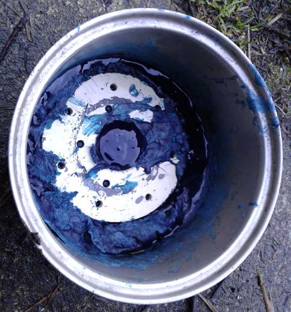
This time I threw in a round steel plate with some
holes in it, thinking the plastic would have a smooth top in that area.
But I pressed it down and half sank it with plastic oozing through the
holes, which made it an inclusion causing concave surfaces in the
piece. When some oozed over the top, the pieces were pretty brittle and
chipped off easily with a hammer and "chisel" (flat screwdriver). But
once again, the main body seemed strong and wouldn't flex much by hand.
It seems the strength is in having solid chunks 1/4" or more thick.
2. On the 20th while it was light out I tried
a second time. Not much
seemed to happen for 20(?) minutes, then it all started to melt and was
pretty much soft to liquid in another 5 to 10 minutes. With a lid the
smoke seemed much reduced. It didn't force its way out around the edges
the way steam does. Perhaps it only smokes if oxygen is getting in? Or
else the vapor pressure is very low?
This time I threw in a round steel plate with some
holes in it, thinking the plastic would have a smooth top in that area.
But I pressed it down and half sank it with plastic oozing through the
holes, which made it an inclusion causing concave surfaces in the
piece. When some oozed over the top, the pieces were pretty brittle and
chipped off easily with a hammer and "chisel" (flat screwdriver). But
once again, the main body seemed strong and wouldn't flex much by hand.
It seems the strength is in having solid chunks 1/4" or more thick.


Results
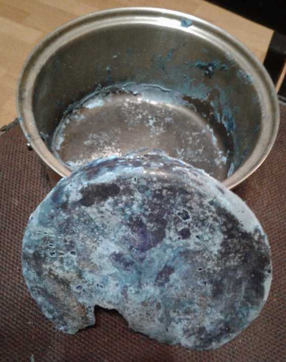
In cooling, the plastic shrank away from the sides of the
pot. It shrank almost 3/16" from a 7" diameter pot to 6-13/16". There
was something to know: a mold would have to be a little bigger than the
desired part size. And inside convolutions might be a problem as the
plastic would try to shrink around a solid form and would probably
crack. (Perhaps normal technique is to eject the part from the mold
while it's still pretty hot and pliable so it can then shrink evenly?)
Speaking of ejecting, I took a screwdriver to pry the piece out. It
came loose pretty easily. That surprised me a bit, because the pot had
had melted solder(?) and crap in the bottom from an old experiment,
which I thought it might stick to. Some metal actually came up with the
plastic. There were still a couple of places where you could tell it
had been a rope, but mostly it was just blobby plastic on top. The
bottom was the shape of the pot and essentially smooth except for a few
small voids. There were smooth dark blue areas that seemed to be solid
plastic, and lighter blue patches that felt perhaps porous and probably
had air bubbles. The piece was good and solid, about 1/4" thick but it
varied. I couldn't break it by hand. It was 140 grams, very light
compared to metal. (Too bad I didn't weigh the rope originally.) If it
had been a uniform thickness of say 3/8", it would have made a very
tough chassis/body piece that would withstand most any abuse (except
heat) with almost no flexing.
2. The second piece initially weighed 228g (1/2 a pound). When it came
out it was 157g. Perhaps all that smoke is the polypropylene
depolymerizing and escaping as cyclopropane gas. (Per expectations
after seeing the shrinkage of the first one) it cracked at its thinnest
points around the rim of the included plate. The bottom surface was
smooth, but the top surface under the plate was pretty rough. Perhaps
this might be improved, but this one would have needed some sort of
surfacing after to be aesthetically acceptable. (An area of paint came
off the plate and stuck to the bottom of the pot.) It was probably
better melted than the first piece and there was more dark color and
less light blue.
Conclusions
It didn't liquify to become as fluid as hoped. (The second
time was better than the first, but the viscosity was high.) A simple
open pot mold on a hotplate won't make a flat top surface. A pot mold
with a fitted lid that could be strongly pressed down, in something
like an oven that could make uniform heat might work, provided that the
molds are very simple and make just convex or flat parts. Disc and flat
rectangle plate "blanks" would be pretty simple to do. Of course,
simple discs or rectangles can be turned to exactness on a lathe or cut
to size and shape, and then have bearing mounts, bolt holes and so on
machined in.
From the ease of cracking off the thin bits, I would guess
it's not as strong after being melted. The thin walls of a PP ice cream
container I have bend and flex rather than cracking. Perhaps the
polymer chains get
shorter. It's still pretty tough, but it might be that one should make
the parts a little thicker to compensate. The tight lid keeping air out
and the smoke in might help or even essentially prevent this problem,
if it is one.
Any complex shape would have to be easy to remove from the
mold while still pretty hot, before it shrinks and cracks around
projections into the plastic.
On the 20th I found a potential "burner" for larger disks
or plates. It was the electric barbecue I got in 2008 for early battery
chemistry experiments. The 1500 watt element went back and forth across
a much larger surface area than a hotplate or stove burner. It could
heat the bottom of a large pot or pan. And I still (somehow!) had the
box of kiln blocks I had cut to make it into a sort of oven. This is
worth at least some further experiments another time.
For mass production, it would be better to leave it to the
pros and be happy to get uniform finished parts ready to assemble. But
I'm sure they would object to recycling beach plastic in their
equipment.
Other
"Green" Electric Equipment Projects
Carmichael
Mill - AKA "Portable Bandsaw Alaska Mill"
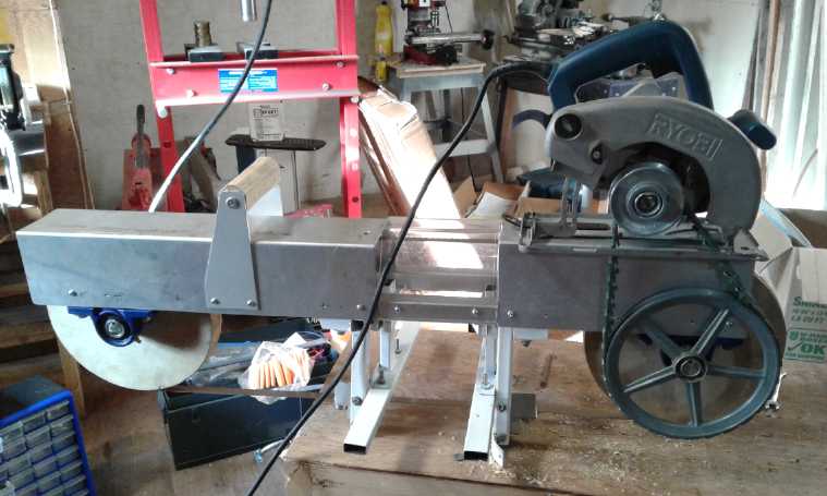
The chief news here is that
I got the mill running and cutting wood. This project had no major
unknowns in its conception. There was no novel chemistry, physics or
material science of uncertain characteristics to be delved into.
Bandsaws have been made pretty much the same way mechanically for a
long time. If it was built well enough with no big design mistakes, and
didn't end up being too heavy or cumbersome, it should work. It turned
out the band guide bases probably weren't strong enough as the
alignment soon went out. But it
certainly was gratifying to have a project that didn't take ages to
build and that worked as it was supposed to on the first try.
If I can find funding this is certainly something to be
perfected and commercially manufactured on a considerable scale. If
not, it's still the future. It's harder to make than a frame to hold a
chainsaw, but the simple video of it cutting, posted to youtube, will
surely inspire others to start making them.
Building, continued
After putting in the ball bearing band guides, I turned to
doing the adjustable feet to set the depth of cut, AKA the thickness of
the boards being milled. I had only some vague ideas of how I might do
this.
I got out of thinking they had to be transverse like the ones on a
chainsaw mill, and instead could be a pair of "skis", one on each side.
I cut two pieces of rectangular steel tube for the skis. The left over
end with a welded-on "T" with bolt holes caught my attention. The skis
could be bolted
to the "T"
if the piece could be slid in and out from the middle without hitting
the back of the band and yet still adjust to do very narrow boards, eg,
to
1/4" for spruce guitar bellies, or for the thin edge of bevelled
siding. (Since the skis adjust separately, bevels might be cut - a good
advantage.) Checking this out, it seemed that this setup would limit
the maximum
cut depth to about 4" instead of 6", or the ends of the legs would hit
the top of the band loop. That seemed like an okay trade-off for the
prototype for now. On the 12th I milled slots in chunks of aluminum
bar stock.
Horizontal slots on the back would hold them securely parallel to the
saw. Vertical ones on the front would hold the "leg" bars securely
vertical, while allowing them to slide in and out with the bolts
loosened. I was going to just make a flat piece to clamp each leg into
the slot, but finally I milled more aluminum blocks for that side too,
as I pieced it all together on the 13th.
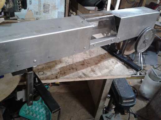 L: one of the mounting blocks for the sliding
legs and feet or "skis". (I found flat head bolts later.)
L: one of the mounting blocks for the sliding
legs and feet or "skis". (I found flat head bolts later.)
R: The mill could cut wider than the radial arm saw table depth.
It's okay for for
cutting already edged cants into boards. The ski
spacing (width) adjustment will need improvement for irregular width
log cutting.
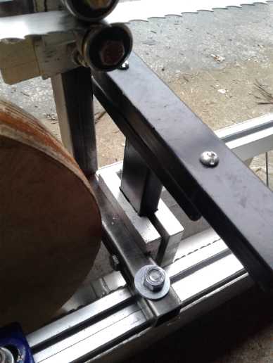
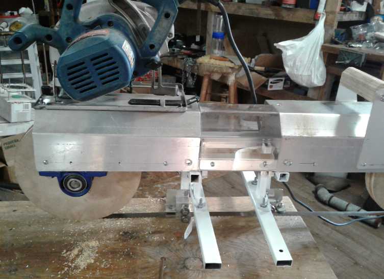
On the 16th I spray painted the pieces that form the arms
that hold the band guides and the depth adjustment legs and 'skis' or
skids.
The saw band motion pulls the mill until the right
side is against something. Here there has to be a side skid below the
cut line, just as on the Chainsaw type. I had mine picked out, but to
attach it it needed something I don't enjoy doing and am not very good
at: welding. (and oops, I should have done that before the painting.)
I had also been considering how to hold the mill for
carrying and cutting. I came up with the idea of bicycle handlebars.
The brake handle and cable could be used to turn on the motor. It
looked like they'd be hard to mount. But something like them then,
round tube with a plate attached to each "ski" might more doable.
Keeping the brake handle and cable. That would mean more welding to
attach the tubes to their mounting plates. (I should try to do all the
welding at once.) Also bending the tubes to a good shape looked highly
desirable, but I had no pipe bending equipment.
On the 18th scraped and wire brushed the paint off, welded
the skid on, repainted and also painted the "legs" and "skis". "Dries
in 2 to 4 hours, completely dry in 24 hours." Whatever happened to the
great spray paints that used to dry in a couple of minutes - almost on
contact? In 1996 in the middle of making my pivoting blade sawmill,
quite suddenly I couldn't get decent spray paint that dried properly
(at all) and have never had any that's much better since. It doesn't
dry and doesn't dry and drips run, so you have to paint thin coats,
hours apart, instead of going back over thin spots immediately after
finishing the first coat, since it's already dry enough to do so. If I
remember right, I think the government came out with some new
"environmentally friendly" paint formula regulations at the time. They
must have banned whatever it was that made spray can paints work well.
The bicycle handlebars idea didn't look so good. The ones
I found were straight instead of curved around, and I didn't see any
very good way to mount them. On the 22nd I finally figured out how to
make a simple handle on top of the saw and I cut pieces of aluminum for
it.
 On the 24th I
finally got a few hours to work on it. I
finished making and mounted the handle. Then I drilled two bolt holes
to mount the
Ryobi skill saw, in both the saw's plate and in the top of the mill, by
the right end of the mill. I mounted the saw. Then I got an 8" V-belt
pulley (off
my old sawmill!) It was the biggest pulley I had with a 3/4" shaft
size. I couldn't find a V-belt that would fit (about 28"), but I made
up one from a "link belt". Everything was installed except the cooling
water system and some safety covers. The saw trigger was in an awkward
position, as expected, but that could be excused for initial testing.
There was
an end handle on the skillsaw. Combined with the one I had mounted, the
mill
could be picked up from the top with both hands (and without risk of
accidentally
starting it). It weighed 38 pounds - not much different than the
chainsaw mill but more balanced to lift with both hands. It rests on
the side skid and the left "strut" that holds the band guides. I hadn't
given this any thought. I
should have made the skid longer as it just barely balances and the
mill could
easily fall forward onto its face. (And it tests the strength of my
weld.)
On the 24th I
finally got a few hours to work on it. I
finished making and mounted the handle. Then I drilled two bolt holes
to mount the
Ryobi skill saw, in both the saw's plate and in the top of the mill, by
the right end of the mill. I mounted the saw. Then I got an 8" V-belt
pulley (off
my old sawmill!) It was the biggest pulley I had with a 3/4" shaft
size. I couldn't find a V-belt that would fit (about 28"), but I made
up one from a "link belt". Everything was installed except the cooling
water system and some safety covers. The saw trigger was in an awkward
position, as expected, but that could be excused for initial testing.
There was
an end handle on the skillsaw. Combined with the one I had mounted, the
mill
could be picked up from the top with both hands (and without risk of
accidentally
starting it). It weighed 38 pounds - not much different than the
chainsaw mill but more balanced to lift with both hands. It rests on
the side skid and the left "strut" that holds the band guides. I hadn't
given this any thought. I
should have made the skid longer as it just barely balances and the
mill could
easily fall forward onto its face. (And it tests the strength of my
weld.)
First Tests
 I still had a
few parts to add, but at that point, what
was there to stop me from firing up the mill? I couldn't think of
anything. I lifted the left end so the wheel was more above the table
and
pressed the trigger. Everything seemed to work, but the speed of the
band was scary - much higher than I had figured on. In spite of the
small-to-large pulley pair and only 10" wheels, the skill saw was 5000
RPM, which is a fast place to start from.
I still had a
few parts to add, but at that point, what
was there to stop me from firing up the mill? I couldn't think of
anything. I lifted the left end so the wheel was more above the table
and
pressed the trigger. Everything seemed to work, but the speed of the
band was scary - much higher than I had figured on. In spite of the
small-to-large pulley pair and only 10" wheels, the skill saw was 5000
RPM, which is a fast place to start from.
In spite of a few misgivings, I set out a small 6" wide
spruce beam (irregular with bark on the bottom side) on a
small table. I plugged in the mill and set it in position at the end. I
got a grip on it and pressed the trigger. The band bit into the wood
and seemed to cut nicely for a few inches. I stopped there and measured
the depth. I thought it was probably going down at a slight
angle, but in fact it seemed to be cutting quite straight with no more
adjustments than I had "eyeballed" up setting up the "skis". I cut a
few more inches and it still seemed fine, and it seemed to cut pretty
quickly. No doubt the higher band speed was actually better than what I
had
been aiming for. The "meat cutting" band seemed to spin and cut freely
and easily.
I got out a tripod and
camcorder and took a video of
cutting the next few inches. I didn't want to cut very far at once with
no cooling on the band (and with it being deficient in safety guards
too). Then I did another video showing around the saw. Finally I put
the
camera back on the tripod, marked where the cut came to, and cut about
a foot,
counting off seconds in my head. It was about 10 seconds, so that's
6 feet per minute (FPM) on a 6" wide cut through spruce. When I was
milling
with the chainsaw it was generally cutting somewhere around 4 times
that width and 1/4 that fast, and so might be comparable. But it uses
incomparably less power than the chainsaw mill, the kerf and the
sawdust are almost nothing, and there's no exhaust and far less noise.
I had meant to have working handles farther down and
behind so the operator was pushing more in line with the band (or
should I say less out of line?), but it seemed to cut okay with just
the handles on top. The "skis" were long enough to keep it from tipping
forward.
Next Tests
Since I hadn't cut to the far end, I had to back the saw
out of the kerf. The band, being pushed forward instead of backward,
came off the band guides and had to be put back. The next day (25th) I
resolved to cut off the whole board if the band didn't feel like it was
getting too hot. Backing the saw out must have upset the adjustments.
Perhaps the aluminum holding the bearing guide wheels was too thin? It
didn't cut nicely. First the previously cut kerf had closed up and I
had to hold it open with a thin wedge. But once it was going, the cut
climbed up toward the top and soon I had the backs of the "skis" up in
the air to keep it down. Even at that it cut a cup shape in the board.
Where it had seemed like lots of power, now the motor definitely
labored. I did get to the end, and the band (somewhat surprisingly)
wasn't too hot. The first 2-1/2 feet cut the precious day looked great
and the saw tooth marks were almost invisible, but the rest of the
board was pretty (ahem) wonky.
Notwithstanding, at one point I cut two feet in 16
seconds, making the cutting speed 7-1/2 FPM.
In the shop I found that the guide wheels were now a loose
fit, allowing the band to aim up or down instead of holding it
horizontal. I took them off and ended up putting slightly larger
bearing wheels on the tops to get a tighter fit. Then I took it out and
tried cutting another board. This time, the right side was good, but
the left side rose up more and more over a couple of feet, lifting the
left ski, tilting the saw and giving the board more and more of a wedge
shaped profile instead of rectangular. I had to stop.
Someone said a couple of months ago that he had a small,
cheap commercially made bandsaw mill (on tracks) and that he was
forever fixing and adjusting it. That sounds like a nuisance. Could I
do better? Apparently I needed to do a more robust
job of the band guides so all the adjustments would stay exactly where
they were put. Also it would be much the best if the tilt of each side
was easily
adjustable with a thumbscrew, without removing the saw from the cut.
I didn't remember
other bandsaws needing such exactitude. But with other bandsaws, if it
isn't cutting in the direction desired, one simply adjusts the aim of
the piece of wood being fed in. With practice it becomes automatic. In
this case the saw is being fed into the
wood instead, and changing the aim would mean adjusting the angle of
the guides. (or of the skis, but
the right and left side guides still have to match.)
A youtube video (for a typical bandsaw) said the keys,
rather than being in the blade guides, were a sharp blade, correct
blade tension, and to have the teeth of the band at the apex of the
wheels. More things to think about!
Motor Choices
My original idea was to use the 13 amp Ryobi skillsaw as
the motor. I could simply bolt its bottom plate to the top of the mill
above the pulley and connect it with a V-belt. The Ryobi had its own
belt tensioning adjustment - the cut depth adjustment - and I found
means to attach
a V-belt pulley to it. But I started thinking its power output would
probably be unsatisfactory.
I considered taking apart my 12 amp electric lawnmower and
using its motor (permanent magnet DC, brush type). I wanted to get the
most "bang for the buck" out of an
electrical outlet, which is limited to about 1500 watts input, which is
2 horsepower out... if the motor is 100% efficient. But the higher the
load, the less efficient the motor is. Some are much better than
others. The permanent magnet lawnmower motors seem to be some of the
better ones.
But the very highest efficiency seems to be BLDC, and my
own Electric
Hubcap series motors are at the upper end of those. I tried to
contact a company that showed various models. It looked like they'd
have one that was about right. But they didn't reply to two e-mails.
Not a way to get business! Do
they really have commercially viable motors?
Until then it was never in my thoughts to use one of my
own motors. That just seemed like going to a lot more trouble
instead of just getting the project done. But the Electric Caik
("Mini Electric Hubcap") motor would be just about right for the job,
and it was only 17 pounds. First I thought I would take the one from
the outboard and
use it. Then I thought of the Electric Caik "BLDC4:3" motor, and the
ARM reluctance motor, both made in 2015. (TE News #78 to 95) These were
intended to use a unipolar motor controller, and the performance of my
unpolar controller built at the same time was pathetic. It worked, but
something wasn't right. It needed and still needs more development that
I didn't get to.
But the Caik, I started to realize, would run better with
a regular BLDC
controller. That's still a nuisance, but at least I have a working
controller and some half assembled, that seem reasonably reliable at 24
volts. The 24 volts DC instead of 120 volts AC means I'll have to use
batteries for power. But it may be that it will give more horsepower
than a plugged-in motor, or at least as much.
All well and good BUT... In order to not prolong the
development of the bandsaw mill itself, I mounted
the Ryobi skillsaw for initial testing, and would worry about switching
to a
better motor once the mill was at least running. It was simple to mount
and connect. It seemed to have plenty of power for the first 6" wide
test cuts in spruce. 18" cuts in tougher wood would surely need
more.
Electricity
Generation
Floating Hydro
Power?
After the potential tsunami alert for the BC coast about the 23rd(?), I
gave some thought to tying one of my fat beach-salvaged ropes somewhere
up a tall tree so I could quickly climb it if needs be. Then I thought
that with a little warning I could make my way up Lawnhill road to
higher ground. It was a long walk as there was a lot of fairly level
road before it went up some good hills. I had never walked up it so far
before. (I would use this route only with sufficient warning to drive
up it quickly by car. Otherwise it will be the tree and rope, should
the tsunami
ever happen.)
But on it I crossed a bridge over Lawn Creek where the
water was flowing past rapids. There was more water and more rapid flow
than
I had expected. A power line went up the road. A small floating power
unit, or even multiple units at different points, wasn't out of the
question. At least in rainy times. And there are no doubt other
suitable or even much better bodies of flowing water near power lines
that others might
know of. In that case, the potential is there for developing small
units, later for manufacture and sale for use anywhere where flowing
water is available. My
basic premise would be to keep it small and portable such that two
people could carry and deploy it, eg, 8 feet long and 4 to 6 wide for
use in water at least a foot deep.
There are various components to each unit: floating
"catamaran" hulls, "deck" platforms and structures, propellers and
shafts, a guard grid to keep debris and fish out, generators (the
"Improved Piggott" generators from TE News about a year ago - still
unassembled), and
electrical connection components (notably switches, breakers and
synchronous grid-tie inverters). And these all require various skills
and techniques to make.
I think the thing to do, similarly to my ideas for
floating hydro on the Delkatla tidal estuary in some previous issues,
would be to try to interest others on the island in co-operating on the
project. Maybe it's time to get onto social media and put out a message
to other islanders?
Electricity
Storage
Nickel-Nickel
with Oxalate Battery Chemie
Basically the month went by mostly with nothing to do on
the
project but think a bit and order a couple of chemicals. Then the
chemicals arrived. I got a fitting for the vacuum pump and made
ethaline DES. I've managed to stretch it out
into several paragraphs for the most interested to peruse.
Electrolyte: Potassium Oxalate?
The oxalic acid I ordered from ACPChem.com on December 11th via a web
form still hadn't arrived on January 11th. On inquiring it seemed they
had no record of the order! I was anyway a little nervous about the
prospects for having an acid delivered and how much the shipping charge
might be, so I asked them to send potassium oxalate instead. I already
knew I didn't want to use the straight acid and would be mixing it with
potassium (KOH). So the only untried substance that would be eliminated
was
potassium hydrogen oxalate (KHC2O4). And that didn't look very soluble
in the table, so it probably wouldn't work very well. I began to think
the best electrolyte would
more likely be K2C2O4 or a mix of K2C2O4 and KOH. It seems the pH of
the salt is around 7 to 8.5. That might work by itself, or it might
cause some KOH to form by itself and make it more alkaline. Mixing in
even a little KOH would no doubt take it to pH 14. Using Ca(OH)2
instead of KOH
should make it around 12 to 13, since that is so little soluble. (A
reserve of Ca(OH)2 could remain on the bottom of the cell or in the
electrodes.) At pH below 14 nickel metal should oxidize to Ni(OH)2 as
the desired negative electrode discharge product.
I definitely think I'm onto something with the oxalate.
I've been
trying to chelate electrodes to prevent them from deteriorating, and
oxalate is an excellent chelating agent to go along with the fact that
oxalates of nickel and manganese aren't soluble. But December's
experiment ruled out oxalic acid. Potassium oxalate brings it back to
an alkaline chemistry.
Electrolyte Medium: Deep Eutectic Solvent (DES) - a salt that's
liquid at room temperature - instead of water?
Then too, what about that "deep eutectic solvent" ("DES") I was
planning to make 2-1/2 years ago, as suggested by
Leonardo Janus, in place of water? It's an organic salt. Salt batteries
with inorganic salt electrolytes have been made and work very well, but
there are no
simple or common inorganic salts that are liquid at room temperature
ranges, so
to work they have to be heated well above the boiling point of water to
wherever the salt melts. "DES"es are organic salts that melt
(preferably) below room temperature to give the benefit of an ionic
salt
electrolyte without needing heat. The oxygen overvoltage of most salts
is higher than for water, so there's every chance that it would solve
the self discharge problem in my positive electrodes, a recurrent theme
seemingly in all my cells.
The "ethaline", a mix of choline chloride and ethylene
glycol sounded ideal. It's liquid down to [at least] -10°C. These
ingredients for DES are mentioned in Wikipedia (under
"choline chloride") and Leonardo Janus had sent me instructions on how
to make it. By the time in 2015 I had acquired the chemicals, and a
vacuum
flask, and then Jim Harrington later gave me a vacuum pump as required
to
make it, I had set batteries aside - this idea for over two years now.
This seemed to be a good time to
dig everything out and make sure I had what was needed. The first thing
I couldn't find was the ethylene glycol.
Getting Stuff
Then ACP said they couldn't deliver to a residential
address!, but suggested I try "WestLab.com". This turned out to be a
blessing. It was in Aldergrove BC - much closer for cheaper shipping.
And their prices were a lot lower. So I gladly ordered 500g of
potassium oxalate and a[nother] litre of ethylene glycol from there,
and
it arrived on the 23rd. There was a folded MSDS sheet held onto the
oxalate bottle with a rubber band. It was a good reminder that the
stuff is quite poisonous, including breathing in the dust, and to use a
respirator mask, eye or face shield and gloves. (I thought I was
getting away from dangerous acid and hydroxide. I liked potassium
chloride a lot better from this perspective!)
Another thing I lacked was fittings for the vacuum pump. I
put the pump in the car to take to a hardware store. I definitely
didn't like the idea of trying to order threaded fittings of unknown
size and threads! I went to a cafe for lunch on the 19th. Two of us
started talking and the topic of pumps came up, so I mentioned it. When
we were finished we went to where he had a
pail of fittings. We found fittings that fit the pump and a valve, that
I could solder together using some copper pipe, to evacuate a jar. (I
think they were 3/8" or 7/16" NPT (slightly tapered) threads, but I
didn't realize that until we found that a piece of metal pipe would
thread in.)
Making the DES
The first hurdle seemed to be to be able to evacuate a
jar, which then needed to be rolled around in a rock tumbler while
evacuated. Finally having a fitting for the vacuum pump started making
the difficult look a lot simpler. I found I could just barely squeeze a
plastic tube over the end of the fitting with the smallest end on it. I
thought that the plastic tube might collapse and become flat with a
vacuum, but I had a valve that fit the plastic tube for the other end
and on the 27th I tried it out. It showed no sign of caving in. That
meant I didn't have to use copper pipe after all.
Then for a jar... I thought of how a light bulb implodes,
and how the world's largest non-nuclear "explosion" (implosion) was
done by the Russians a few years back with a huge "vacuum bomb". (But
was it really bigger than the previous record holder, the blast that
destroyed Ripple Rock in Discovery Passage BC, which had been a
notorious menace to shipping?) Canning jars take a bit of a vacuum, but
I thought a beer bottle - small diameter and made for high pressure -
would be safest. (For high pressure I'd have used a plastic
pop bottle - safer than glass. After all, pop bottles used to all be
glass, but I knew the girl who had been blinded in one eye in a grocery
store long ago by an exploding pop bottle, as a result of which news
story glass
pop bottles were discontinued and changed to plastic. And her mother
and grandfather. But those thin PETE bottles would collapse in a
vacuum. ...now, if everyone would stop drinking such apparently
diabetes causing tooth rot anyway... but my digression is digressing.)
I started with a brown glass beer bottle, but realized I would want to
see in and found one that had clear glass. And the tiny mouth could be
covered with a test tube stopper. I had a stopper with a hole for a
glass tube, and the plastic tube fit onto the glass tube. Bingo! That
completed a flexible vacuum line to the pump with a small shutoff valve
to retain the vacuum.
On the 30th I followed Leonardo's instructions for making
it (taking all suitable precautions including safety glasses just in
case the evacuated bottle should implode or somehow spray out chemical):
Proceed in this way:
1-Put 2:1 mole ratio of Ethylene Glycol:Choline Chloride in a jar and
vacuum it for 5-10 minutes than close a valve to maintain the vacuum.
2-Put the jar in a rock tumbler and mix it for about 1/2 hour.
3-Open the jar and put the premixed (should be a jelled white cream) in
a high temp glass and put it in a microwave oven.
Warm it at steps up to 120°C. I use 30 seconds
steps with 600W power and mix every steps.
At end the gel must become clear and has a
crust over it.
Filter out the crust.
Re-heat again to 120°C.
Filter with a filter paper strong for to
80-100°C.
You must obtain a transparent liquid with about 6-10cps viscosity and
about 6mS/cm conductivity.
 When I put the two ingredients in the bottle, the choline sat as
submerged crystals that didn't reach the surface of the liquid glycol.
I did step one. Nothing seemed to happen. Then I took the bottle to my
machine lathe. I set it to low range, but the chuck wouldn't open quite
wide enough to hold the bottle. Rather than start figuring out another
means, I started shaking the bottle. After 15 minutes I put it back on
the vacuum pump in case the vacuum was leaking out (or is it in?) with
all the shaking of the stopper and tubes. Then I shook for another 15.
I opened the valve and there was no vacuum. I put it back on the pump
for a couple more minutes and closed the valve. This time when I opened
it I could hear air sucking in. So it had had a vacuum, but lost it
somewhere over the minutes or in the shaking process - hopefully
gradually. It wasn't a
gel. It was sort of white, essentially emulsified but with small
crystals still visible. (I suspect you're supposed to put steel balls
in the rock tumbler to help crush the crystals and mix the
ingredients.) I assumed it was good enough. I was glad it was liquid
because I
wasn't sure how I was going to get a gel out of the beer bottle.
When I put the two ingredients in the bottle, the choline sat as
submerged crystals that didn't reach the surface of the liquid glycol.
I did step one. Nothing seemed to happen. Then I took the bottle to my
machine lathe. I set it to low range, but the chuck wouldn't open quite
wide enough to hold the bottle. Rather than start figuring out another
means, I started shaking the bottle. After 15 minutes I put it back on
the vacuum pump in case the vacuum was leaking out (or is it in?) with
all the shaking of the stopper and tubes. Then I shook for another 15.
I opened the valve and there was no vacuum. I put it back on the pump
for a couple more minutes and closed the valve. This time when I opened
it I could hear air sucking in. So it had had a vacuum, but lost it
somewhere over the minutes or in the shaking process - hopefully
gradually. It wasn't a
gel. It was sort of white, essentially emulsified but with small
crystals still visible. (I suspect you're supposed to put steel balls
in the rock tumbler to help crush the crystals and mix the
ingredients.) I assumed it was good enough. I was glad it was liquid
because I
wasn't sure how I was going to get a gel out of the beer bottle.
Then I put the
mix into a 100mL beaker. Since it was a
small quantity I tried about 20 seconds in the microwave. That got it
pretty hot and I reduced it to 10 seconds for the next blast or two.
That brought it up to 100°C and I went 6 seconds at a time after
that. It seemed the closer I got to 120° the longer it took, but it
got there. Somewhere it became a clear liquid and above 110° or so
a little vapor
came off each time. I turned the stove vent on full to vent the vapor.
There was no
crust, so I didn't bother with filtering and reheating. There were 3 or
4 tiny black specs in the liquid that probably came from the equipment.
I expect that Leonardo's impure chemicals made that crust. (He had said
something about choline chloride being for chicken feed, just 96%
purity. My ingredients came from a lab supply. His were really cheap,
but I couldn't find them except at the chem places for lab prices.)
I don't know how to measure viscosity, or conductivity in
this context.
After making it, I reviewed some 2015 correspondence from
Leonardo. He had attached some literature about it that I had forgotten
about and hadn't read. Something I had overlooked was that he had said
the DES
dissolves MnO2. That might preclude using the nickel-manganese mixture
for the positive side if it also dissolves nickel manganates, and also
for making nickel-manganese 2-1/2 volt cells. So for now I'll
concentrate
on nickel-nickel with pure nickel [oxy]hydroxide in the "+" side.
http://www.TurquoiseEnergy.com
Haida Gwaii, BC Canada