Turquoise
Energy Ltd. News #117
covering
February 2018 (Posted March 3rd)
Lawnhill BC Canada
by Craig Carmichael
www.TurquoiseEnergy.com
= www.ElectricCaik.com
= www.ElectricHubcap.com
= www.ElectricWeel.com
Month In Brief
(Project Summaries etc.)
- Battery Electrolyte Experiment
- Revised and Revived: the Electric Chevy Sprint Project (the car
moves!) - EV Power
Consumptions - No Carmichael Mill ("Bandsaw Alaska Mill") this month -
More Electric Ferries! (update)
In Passing
(Miscellaneous topics, editorial comments & opinionated rants)
- More Arctic Warming-Accelerating Sea Level Rise-Topsy Turvy Weather -
Spinosaurus: a gigantic Amphibian or a Reptile?
- Project Reports
-
Electric
Transport - Electric Hubcap Motor Systems
* Chevy Sprint Car (again? still?) - Forklift Motor & Fixed (8.9:1)
reduction: The car moves!
* J1772 EV Charging Stations
Other "Green"
Electric Equipment Projects
* Indoor Vegetable Growing With LED Lights
Electricity Generation (no reports)
Electricity Storage - Turquoise Battery
Project (NiMn, NiNi, O2-Ni), etc.
* Nickel-Nickel: DES & KC2O4 Electrolyte Experiment
February in Brief
Battery Electrolyte Experiment
At the start of the month I did an experiment with the new
ethaline DES and potassium oxalate for new battery chemistry. It seemed
to basically work and I have another experiment in mind. Then I got a
motor...
Electric Chevy Sprint Project
This quickly became the main project of the month and most
other things were cast aside for the duration.
Unable to dry it out outside in the damp, I put the
Sprint, dripping wet inside and out and fogged with condensation, into
the garage to dry it out. It took several days to dry in the unheated
air, even with a fan inside. But what was I going to do with it? My own
BLDC motor controllers kept failing. The Kelly BLDC motor controller
was broken and I wasn't sure I could repair it. To use my Electric
Hubcap motor with around a 3000 RPM limit, a car would need a variable
transmission of some sort, and most of the several things I had been
trying had worked better in theory than in practice as far as I had
been able to construct them. (The flywheel and clutch would probably
work but would take a complete rebuild to make an acceptable system.)
Also I was losing confidence that my Electric Hubcap motor wouldn't
overheat if I tried to run a car for a considerable time and distance
with it.
The driver who had given the uncharged Nissan Leaf and me
a ride home to Lawnhill from the barge "bulkhead" (terminal/yard) at
Masset on a tilt deck truck on January 31st, had mentioned he had some
36 volt forklift motors and after a few days I decided I'd like to try
that, and got one from him. They would handle a substantially higher
RPM, although I was unable to find out the rating. The Sprint was
already set up (as far as it was set up at all) for 36 volts. It was
only 51 pounds, but I was assured that it should be plenty, that these
forklift motors are commonly run 10 times their rating - and at up to
72 volts - for long periods without issue. And that the brushes "never
wear out". (My expectation is that this motor with a fixed reduction
ratio 'transmission' should make for a good town car, but probably not
a good highway vehicle. Admittedly that would have been more useful to
me when I lived in town instead of on a highway.)
I did some further explorations with the original
automatic transmission, and figured out how to disassemble more of it.
I found I could use it with just three of the original gears at the
back, giving a fixed 8.9 to 1 reduction with low losses. Once I figured
out how to connect a shaft to this gear that wasn't intended to have
one, the whole path to making and installing seemed clear, and that got
my enthusiasm up and running. I spent a good part of the month making
the shaft and fittings. Owing to the cold I brought the transmission
inside to the kitchen floor and worked on it there, going out to the
shop for various tasks and returning to the warm.
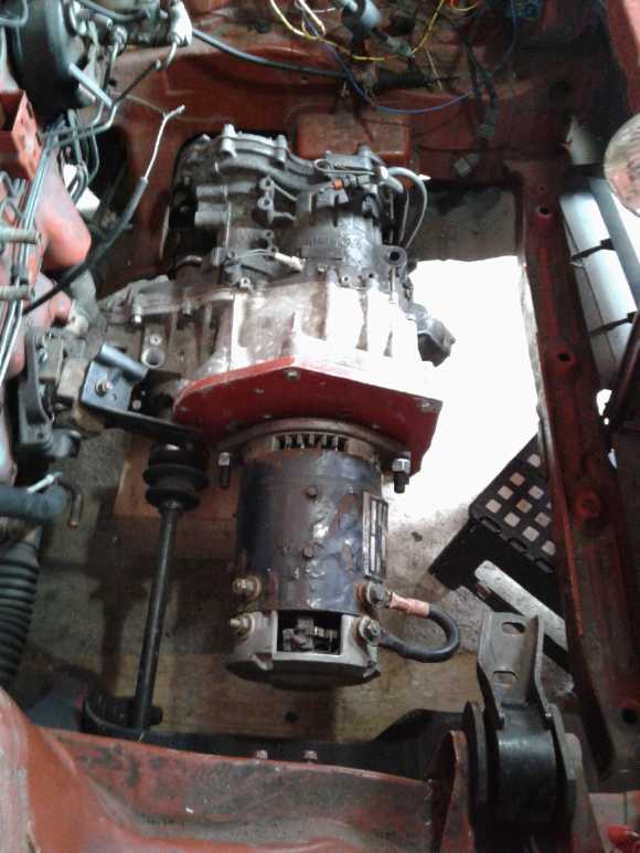
By the 24th the transmission was done. On the 25th I ran
the motor. It ran different speeds with different voltages, and drew
about 15 amps regardless of voltage. Then I cludged a 1" shaft Lovejoy
connector onto the motor with a spacer tube and set screws, and fitted
it onto the transmission. I installed them in the car in the garage
(Wow, a garage!). The cement floor made for easy rolling. Using a
4-cell lithium battery and jumper cables beside the car, it backed up a
bit with 6 volts, more with 9 volts, and up a slight incline with 12,
drawing around 75 amps each time.
With that working I ordered a Curtis "separately excited"
300 amp motor controller (model 1243-4320) with all the features
iincluding forward-reverse, regenerative braking and safety features.
That wouldn't have cost too much except I felt I would have to get a
Curtis programmer as well, and it was almost twice as much as the
controller. The order came to over 1000$C. Suddenly the project was
getting pricey! But I don't think it needs much else that I don't
already have.
If it worked really well and if it had the range, perhaps
I might sell the Leaf and have money for other things instead of a
debt? But I'm probably dreaming. I like the Leaf's heated steering
wheel and heated seats, which allow me to minimize use of the energy
sucking car heater. And it's clean and new, and the quietest
car I've ever had not only because it's electric but because of good
sound insulation. The 1990 Sprint, sitting out in the cold and damp
over several winters now, would take some cleaning up and outfitting
inside just to have a "nice" feel to it again. I did some of that in
the last days of the month, and at least it looked decent again.
What is it then besides a "regular" if somewhat unusual
car conversion to electric? Perhaps not much, but at least it'll be
working. AND once it's going it can help longer range plans: I might
then get another 36 volt forklift motor and parts to "hybridize" the
Toyota Echo instead of using the 96 volt Curtis stuff from the Swift.
(...and save that more powerful system for the ground effect craft?)
I would also like to try doing a better and "permanent
magnet assisted" reluctance motor, probably with my novel unipolar
motor controller, and swap out the forklift motor for that. A
reluctance motor could easily handle the high RPMs at highway speeds
with the fixed transmission ratio, and somewhere in the
"permanent magnet assisted" is that elusive 500 mile driving range.
That would be really exciting!
Nissan Leaf and EV Power Consumptions
 Buying the
Leaf is the first time I've ever been making monthly payments on a car
instead of having paid cash. The price figure was double what my white
Toyota Tercel wagon (my only new car ever) had cost in 1986. But a used
Leaf is about as economical as a good, commercially made electric car
gets at this time.
Buying the
Leaf is the first time I've ever been making monthly payments on a car
instead of having paid cash. The price figure was double what my white
Toyota Tercel wagon (my only new car ever) had cost in 1986. But a used
Leaf is about as economical as a good, commercially made electric car
gets at this time.
In driving the Leaf, I noted that a display could be
called up with watt-hours per kilometer - actually stated as
"kilometers per
kilowatt hour". (Why?) It seemed I was averaging 5 to 6, or 167 to 200
watt-hours/kilometer. This was on a par with what the Mazda RX7-EV had
used, except I was mostly doing around 80-95 Km/Hr instead of 50, so it
was definitely better. I dropped down to 75 Km/Hr or so and the average
consumption dropped to 7 or more, ie, 140 WH/Km or less. This was
probably
not dissimilar to the Swift, where I noted 120-130 at lower speeds. The
biggest problem with the Swift was that it only had 10 KWH of battery
capacity. The Leaf has 26. Permanent magnet assisted motors promise to
vastly increase
vehicle range and are worth pursuing.
With the almost ideal "no
stopping necessary anywhere" road conditions and no steep hills (not to
say no hills, however) on Haida Gwaii's main highways, I made the 15 Km
high speed highway trip and the following 10 Km low speed limit section
to and from Queen Charlotte, and the faster highway to Port Clements
once. Over a couple of days I plotted consumption at relatively
constant speeds and got the following.
Speed - Reading - Consumption
Km/Hr - "Km/KWH" - WH/Km
100 - 5.3 - 189
90 - 5.8 - 172
85 - 6.4 - 156
80 - 6.9 - 145
60 - 8.1 - 123
50 - 8.8 - 114
This makes it probably the most efficient electric car
I've had. The Mazda RX7 EV took around 170 to 200 WH/Km, and the Suzuki
Swift 120 to 140, just for city speeds driving, albeit with a lot of
stop and go with traffic lights and stop signs in Victoria, which
doesn't make for very fair comparisons.
Yet if I recall the figures properly, GM's EV1 in the late
1990s used as little as 125 WH/Mile (78 WH/Km), with a simple induction
motor (7000 RPM, 102 KW) and fixed ratio transaxle. That must be for
city driving speeds, but at 1.9 the EV1 had the lowest coefficient of
drag of any car ever made. The 26.4 KWH NiMH batteries - virtually the
same energy storage as the Leaf has - gave the two seat, 3000 pound EV1
a 160 mile (273 Km) rated range, attained or exceeded today perhaps
only by Tesla models. (The Leaf is rated 160 Km. They don't get their
"rated" range in most real driving conditions.) Here's an EV1 highway
speed figure from the web: 164 WH/mile @ 65 MPH, = 102 WH/Km @ 105
KmPH. That's really impressive, looking like just over 1/2 the power
consumption of the Leaf at high speeds. (That spec from
PlasmaBoyRacing.com - the "White Zombie" electric drag racing guy. He
now has an EV1 motor and transmission, bought by some clever person at
an auto parts store just when the EV1 cars were all being recalled and
crushed!)
Why can't we do as well today as they could 2 decades ago?
Lithium batteries are lighter (and supposedly better) than NiMH.
Internet?
My internet seemed to be getting worse again, and became
basically non-functional by mid month. I could only attribute it to
rain and then ice. On the 19th I went out and scrubbed the lichens off
the face of the antenna dish and washed it. Wow! Everything came back
to life! (Sigh, still nothing like fast. But working.) But a few days
later it had quit again. I unplugged the repeater and plugged it back
in. That seemed to do the trick that time. A couple more times and I
was sure that was it: when it quits, reset it. Complicating the picture
was that one computer would be working and others wouldn't connect. One
would work on WiFi but not with an ethernet cable... or sometimes,
vice-versa. Even one program would connect and another wouldn't on the
same computer. Cleaning the dish was probably irrelevant, but re-aiming
it
a bit improved things considerably. (Oh for a Wi-Fi signal strength
meter to know when it's optimum! The repeater itself has LEDs for steps
"poor-weak-fair-good-excellent", but it's never been above "poor".
Apparently there are many shades of "poor".)
Notched V-Belts and Needle Bearing U-Joints
Looking on line on the 19th (while looking for Lovejoy
Couplings), I found a couple of other things I hadn't known about
before. First, the notched V-belts I had recently noted as being
probably better than the regular ones are called "cogged V belts".
There were some on e-bay and I may order a couple for bandsaws
including the mill.
And some readers may recall me wanting to do the 90°
drive shaft bend at the foot of an "electric outboard from scratch"
with two U-joints from the vertical shaft instead of beveled gears,
since I think losses would be lower and 1 to 1 would be an optimum
ratio. PrincessAuto.com has "high torque U-joints" with needle bearings
that work to 45° (nominal I trust rather than absolute max), from
1/4" diameter shafts up to 1". Now if I ever get back to that project I
know where to get them.
No Carmichael Mill ("Bandsaw Alaska
Mill"), this month
Owing to cold weather I didn't go out in the 3° shop
to do this sort of work. Instead I got involved in the Sprint
conversion of longstanding interest. And I spent a few days filling out
tax forms for (ahem!) 2016 for Turquoise Energy before it was too late
to claim the SR & ED tax credit. That had been neglected owing to
complications from the move - busyness, papers in a storage locker, and
having no internet. Once I was into
those, everything else got set aside. (But I'm sure to get back to the
bandsaw soon if only because I have a lot of lumber to cut.)
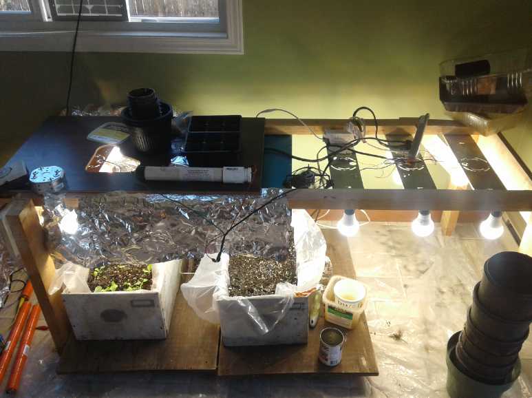
LED light system and Vegetables
One thing that was only 3/4 subverted by the car project
was planting vegetables under the LED light system made in January. At
least I had some good leaf lettuce coming by the end of the month.
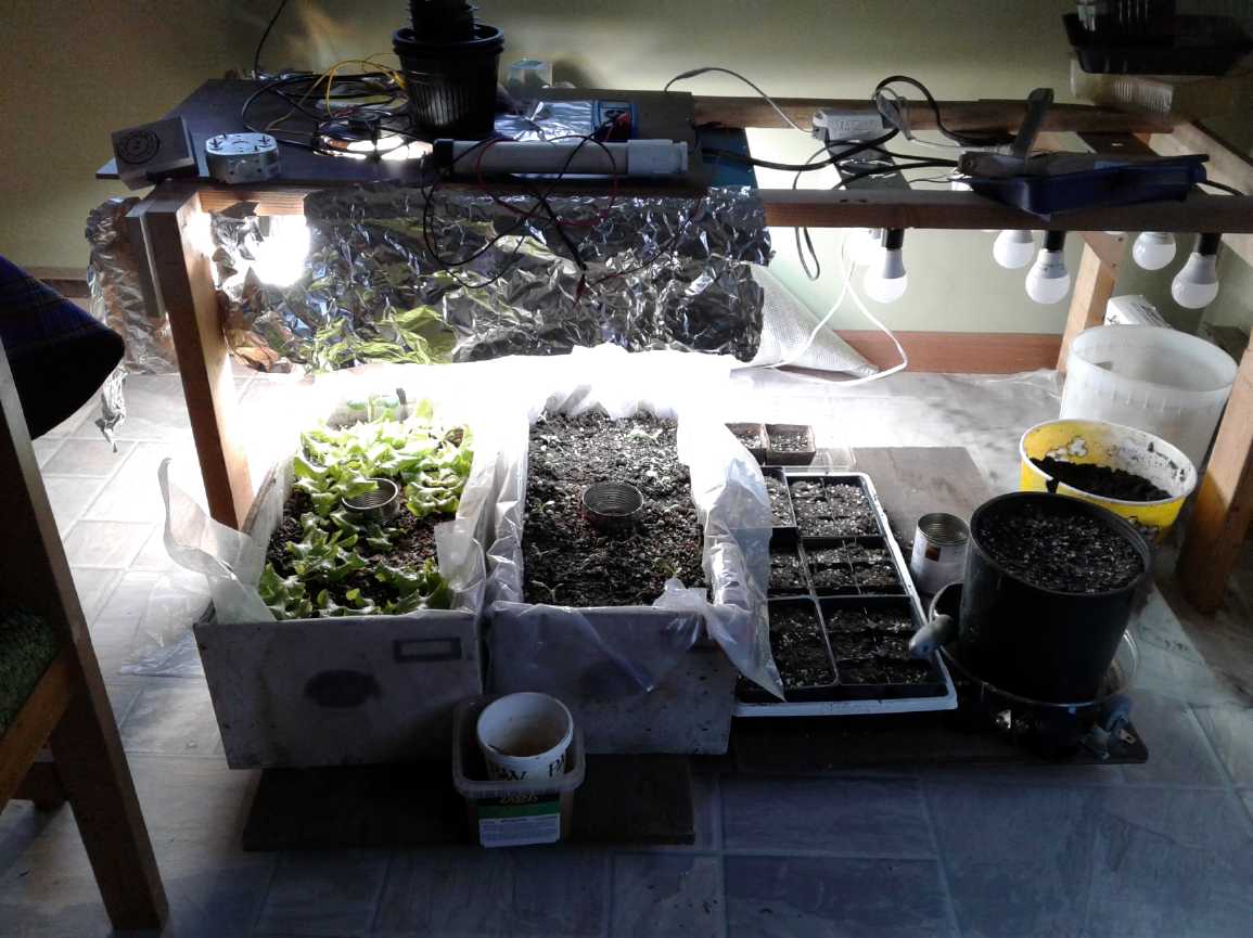 The vegatable grow-op at the end of February.
(I should certainly have got more planted by now!
See detailed report below for more.)
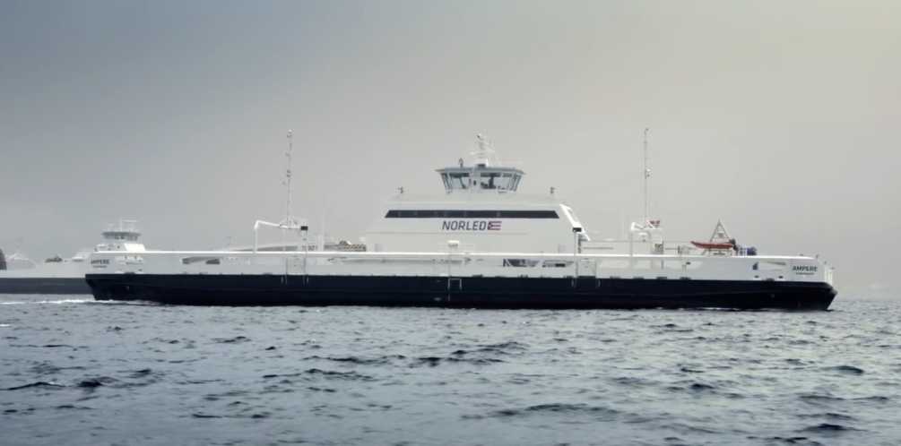
More Electric Ferries (update)
In Turquoise Energy News #60 (January 2013) I noted that
an
all-electric ferry was being built for service in Norway starting in
2015. This would be great for many short routes where extended range
isn't a requirement. Apparently it wasn't just "vaporware". The Ampere
has been running since May 2015 and the operator has got some good data
on
performance. It has cut emissions by 95% and saved 80% on fuel costs,
and of course it's much quieter.
The difference was so apparent that
they quickly commissioned another one, the Elektra, which went
into service summer 2017.
Shipbuilder Fellstrand now have orders
for 53 of them - a big waiting list. Two large ferries are also being
converted to electric (to become the world's largest electric ships),
there were said to be electric barges launching last fall and China is
building an electric cargo ship with 2.4 MWH of batteries.
These are very good signs for the future!
In Passing
(Miscellaneous topics, editorial comments & opinionated rants)
More Arctic Warming - Sea Level Rise Accelerating - Topsy Turvy Weather
Victoria and Vancouver got some heavy snow in February. Up
here in the north, we got rain, heavy frost at nights, and a bit of
snow that turned back into rain. One day we had a brief blizzard with
no wind and the biggest snowflakes I've ever seen. They looked like
about 3/4 of an inch across with a few here and there a whole inch.
They looked a bit lopsided, like upside down jellyfish or umbrellas,
with few crystal protrusions on the bottom - perhaps they were partly
melted. But they fell slowly, not like rain. I'm sorry I didn't think
to get a picture.
New findings seen on a TheWeatherNetwork.com article
indicate that while global sea level rise due to warming has been
thought to be relatively constant, it is actually accelerating. It is
now thought that seas could rise two feet by the end of the century
"threatening US coastlines". (Thank goodness it's only "US"
coastlines!) I think they are still erring on the low side by looking
only at past data. It could easily be three feet or even much more.
The rise comes from two sources: melting glaciers both in
Greenland and Antarctica are adding water to the oceans, and also the
water,
on average warming, expands. But once much of the ice has finished
melting,
the water warming trend can be expected to accelerate as cold ice melt
stops entering the seas. Plus, Antarctica and Greenland can certainly
be expected to uplift geologically as the weight of glaciers on them
diminishes,
displacing still more water toward the other continents.
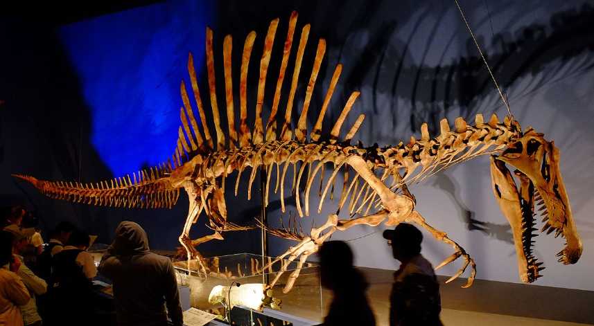
Spinosaurus: a gigantic Amphibian, or a Reptile?
Spinosaurus is a puzzling creature. On a whim I did a
search for "Spinosaurus bone microanatomy" and came up with a report on
this Cretaceous Period creature that mentions some of the things that
I've noted seemed to be characteristics of early amphibians of the
Permian Period. (Semiaquatic adaptations in a giant predatory
dinosaur , science.sciencemag.org/content/345/6204/1613 , Sept 26
2014.) While still calling it a "therapod dinosaur", it was noted to be
unique in being "semi-aquatic", and unlike therapods it had non-hollow
bones in order to have neutral buoyancy in water. It had a small pelvis
compared
to therapods because it walked on all four legs instead of two. The
proportions and joints of the legs and feet seemed to be adapted for
swimming. (The feet were doubtless webbed.)
All this adds to the fact that it had the huge sail on its
back, that I identified as providing extra moist skin surface compared
to body size for amphibians' more primitive respiration, allowing
larger body sizes. (See Turquoise Energy News #100, also #112) The
description of the sail bones fits with it being well supplied with
small blood vessels for such transpiration.
Was it a unique oddity of evolution? In the swamps and
lagoons of North Africa, in an environment somehow free of crocodiles
and other fierce reptilian predators, did the most colossal,
piscivorous "salamander" that ever was, evolve and grow to be gigantic?
The text sounded convincing
to me, but then I looked up images of the skeleton and other than the
sail it seemed to have reptilian features dissimilar to the Permian
amphibians.
Whatever it was, it must surely have inhabited a swampy
environment teeming with food - big fish, water birds, frogs, turtles
and flying reptiles... A region where both fierce land
predators and large water bound creatures would have had trouble
getting around, where a large creature would have to be able to pass
freely through both environments.
 Well, the sail by itself would definitely
indicate to me it's an amphibian. What use would it be to a reptile?
Well, the sail by itself would definitely
indicate to me it's an amphibian. What use would it be to a reptile?
But the rib cage seems more reptilian in form and the breastbones
definitely seem much lighter than in the Permian amphibians.
Most probably then it's a reptilian therapsid? (surely not a theropod?)
Anyway I'll take a wild guess that this creature grabbed prey with the
front teeth,
pulled its neck back to lift it out of the water and above its head,
then opened its jaw
and the victim fell back into its mouth, to be shredded by the teeth
farther back and swallowed in chunks.
(Image: Wikipedia - "Spinosaurus in Japan Expo, 31 May 2016, by Kumiko")
Also of considerable interest to me were reader comments below
the article. One "Bruce Lee" had copied in relevant sentences from
Turquoise energy News #112 about the possibility Spinosaurus was
amphibious, "a later day Dimetrodon". Responses were unfavorable. He
then put in sections from #100 about Permian period creatures being
amphibious rather than reptiles and got more of the same. But the
responses weren't real refutations - merely people pointing out what
current beliefs are and that these didn't fit in and so must be wrong.
But it gave the open minded new ideas to think about beyond the
authors' information and their implicit assumptions in the article.
It seems to me noteworthy that it carried the narrative
beyond, or around, established channels of "peer reviewed" input. Fresh
ideas from
an "outside" source were presented for anyone to read. The "outside
world's" voices can now penetrate the ivy halls of academia!
My compliments to the authors for their fascinating
Spinosaurus research and findings, and thanks to "Bruce Lee" for having
read and for presenting my ideas, potentially broadening the narrative
about this creature and more indirectly through the reference
containing the title Turquoise Energy News #100, about the
sequence of evolution in the Permian.
===
Measuring Fruit: 1 pear = 1/2 a pair, and it's even less if it's been
halved or pared.
"in depth reports" for
each project are below. I hope they may be useful to anyone who wants
to get
into a similar project, to glean ideas for how something
might be done, as well as things that might have been tried or thought
of... and often, of how not to do something - why it didn't
work or proved impractical. Sometimes they set out inventive thoughts
almost as they occur - and are the actual organization and elaboration
in
writing of
those thoughts. They are thus partly a diary and are not
extensively proof-read for literary perfection and consistency before
publication. I hope they add to the body of wisdom for other
researchers and developers to help them find more productive paths and
avoid potential pitfalls.
Electric
Transport
Chevy Sprint
Car - Forklift Motor & Fixed (8.9:1) Reduction
For some days I tried to dry out the poor Sprint, with
fogged windows and wet throughout, by putting a big fan in the driver's
door window. But every day it rained, either preventing me from trying
or catching it with the windows down. Finally I pushed it into the
garage on the 5th. It still took days for the fan to mostly dry it out,
but at
least it didn't take a pile of electricity like a heater would have.
And again I gave some thought to electrifying it. Perhaps
strangely, and perhaps I'm just being stubborn, but getting the Nissan
Leaf hasn't quelled my desire to make some sort of success of this long
protracted project.
 The driver who brought my new (low on charge) Leaf from Masset to
Lawnhill had said he had two or three forklift motors. I
got his phone number and called. He said they were 3.3 KW, 36 volts. He
said they should have plenty of power to drive a small car like the
Sprint. They were "overbuilt" for their nominal ratings and could be
stepped up as high as 72 volts if desired. People had used them at ten
times their rating continuously without problems. He had used one
before on an
electric tricycle that turned out to be insanely powerful and was
passing cars on the road. That sounded
promising. I would much rather use a lower voltage motor if it works
out, as battery arrangements can be so much more flexible.
The driver who brought my new (low on charge) Leaf from Masset to
Lawnhill had said he had two or three forklift motors. I
got his phone number and called. He said they were 3.3 KW, 36 volts. He
said they should have plenty of power to drive a small car like the
Sprint. They were "overbuilt" for their nominal ratings and could be
stepped up as high as 72 volts if desired. People had used them at ten
times their rating continuously without problems. He had used one
before on an
electric tricycle that turned out to be insanely powerful and was
passing cars on the road. That sounded
promising. I would much rather use a lower voltage motor if it works
out, as battery arrangements can be so much more flexible.
How ironic to find a promising motor source the very day I
took delivery of a Nissan Leaf in lieu of not having managed to get the
Sprint on the road!
The transmission box I had made could accommodate no more
than 4 to 1 reduction ratio unless I changed the big #50 sprocket on
the differential. (with just 12 teeth on the input gear, to 48 on the
differential.) Or, the car's original automatic transmission with most
of the parts removed had that same reduction (3.9:1) with
little apparent friction. Compared to the Toyota Echo where I had
thought 6 to 1
reduction would be a good minimum, the Sprint had wheels effectively
about 20" in diameter instead of 22" (normal tire inflation for both),
and it was lighter: a lighter frame with no gas engine and all its
components. Further, the AC motor I was going to use has lower torque
at low RPM.s. For a while I thought, if a forklift motor had enough
torque at low RPM, perhaps it could
use a 4 to 1 reduction to drive the car. Or if not quite enough,
perhaps with a flywheel and centrifugal clutch to get it moving. If
that still didn't do it, I could put in a planetary gear with flywheel
and clutch that would also give it more reduction, eg, 1.8 to 1 for
around 7 to 1 total.
But I hoped it would work just connected straight in. My
plan was to hook it up that way, then take lithium batteries and see
how many connected cells - how many volts and amps - it took to coax
the car into motion, first on level pavement and then going uphill on
various grades. If it looked "good enough" I'd use it that way.
If this motor performed as hoped, the Sprint sounded once
again like the simplest car electrification project. Notwithstanding a
little extra weight (65 pounds), I decided on the original transmission
- just the back end gears in it - as being
easiest and best. The mountings would fit, the speedometer would just
plug in, and some oil inside would lubricate the gears and
bearings.
One thing that worried me was a motor controller. If a big
DPDT switch was used to reverse the armature coils and hence the
direction, it could be
simple PWM, single low side MOSFET drive only - much simpler than
triple
Hi-Low drive BLDC controllers. But it would still have to be made - or
bought.
Sheldon seemed to have made one or some, but he was rather vague on the
details. Or perhaps I should just look up Curtis (or other) controllers
and get a known good commercial model.
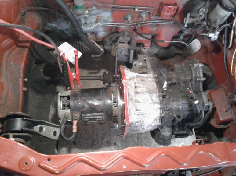
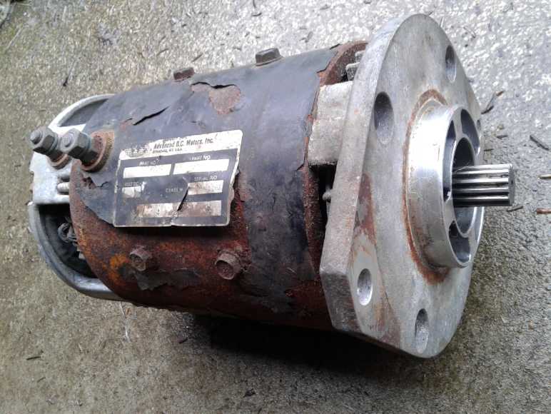
On the 7th I drove to Masset and picked up the motor
(100$). It was pretty rusty, and it had one little problem: there was
only one bearing at one end. On the forklift, the transmission had
supplied the bearing for the shaft end. Here the car transmission also
had only one. Somewhere it would have to have another bearing.
On the 8th I plugged holes in the transmission case where
parts that were no longer needed had been. Then I found and tried out
the mounting bolts and found it necessary to do some "unclogging" of
dirty or corroded bolt holes to get them in. I was glad I checked that
out in advance and not ended up doing it on my back under the car. I
installed the CV drive shafts and then the transmission. (I had thought
an electric winch on the ceiling to lift it would be nice, but the
ceiling was a long way up to get to in the cluttered garage, and it
really wasn't so heavy. I set it on a bench just outside the hood so I
could stand inside and lift it, and put some blocks of wood on the
floor to hold it roughly at the right height. It all went pretty
smoothly.) Cold tho it was, it was nice to be working in a garage
instead of outside on dirt. I probably wouldn't have started.
I dug out the end plate from the Suzuki Swift. It fit on
the automatic
transmission as well as the manual, so there was a good part. The hole
in the center (stepped, with two slightly different diameters) didn't
quite fit the forklift motor. The plate was too big to put on my lathe,
but I could either use it as-is with a slightly sloppy fit in the outer
recess, or
perhaps grind out the inner hole until it fit right in. The motor's two
mounting bolt holes also didn't line up with any of the 12 others and
so the plate would need two more. To use it would be convenient, but it
would preclude the flywheel and centrifugal clutch idea - the whole
drive would be inside the transmission and I couldn't fit them in.
Satisfaction didn't last
long. Overnight I decided I was dreaming to think that 3.9 to 1 would
be enough reduction with that small motor. And all the more so with no
way to fit a clutch and flywheel. If I put in the double sun gear (or
the entire rotating assembly and locked it all together), it gave about
8.9 to 1 reduction. With the second planetary gear (assembly unlocked),
it was about 11 to 1. But these arrangements got into the strangeness
of the internal clutches. The inner one slipped if you tried to turn it
backward, so there would be no way to back up. OTOH, with the simple
PWM motor controller, it might be easier if the transmission would do
reverse than having to reverse the motor rotation. That would mean, at
least, disassembling the transmission and re-installing the shift
lever. Maybe that would get it to go the other way. Out came the
transmission again!
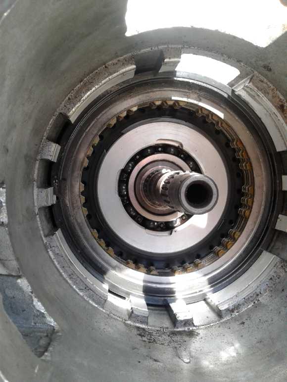
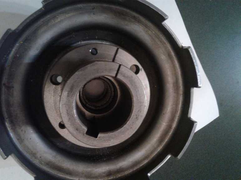
On the 10th I brought it in from the cold to work on the
kitchen floor without freezing. The key was in that last end I hadn't
been able to get into. Then I noticed that two rings that I thought
were parts of machined pieces were actually circlips. What I hadn't
been able to remove from the outside could, and in fact should, be
removed from the inside. I got out the last planetary gear and the
diabolical ring that made its planets assembly slip in one direction
but latch in the other. (This planets assembly was in a "drum" that
covered over outside of the ring gear.) This was what had made it slip
whenever I tried to get it to go backward. At the very back was a
"clutch" on the same planets gear housing, that could be locked or
released. If it was released the rest of the mechanism could be locked
up to get the 4 to 1 ratio from the engine. If it was latched, turning
the double sun gear gave the 8.9 to 1. A big "dish" plate attached to
this sun gear. Ungainly, but in lieu of anything made for the job, that
was the thing to attach a drive shaft to.
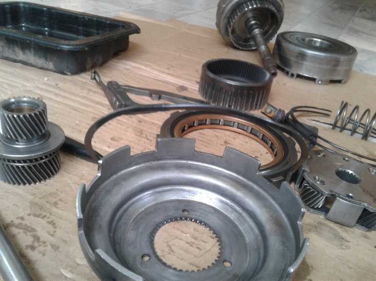 Puzzling over transmission pieces.
Only a few went back in.
(Note the giant flat circlips (center & right center) that were
what was holding everything in.)
 This diabolical cogged outer ring let the
planets assembly spin "freely" in one direction,
This diabolical cogged outer ring let the
planets assembly spin "freely" in one direction,
and locked it in the other. I wanted the car to go both directions!
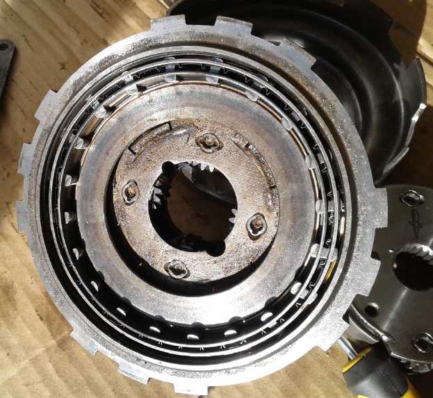
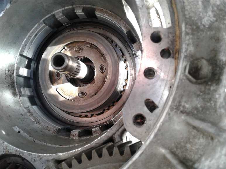
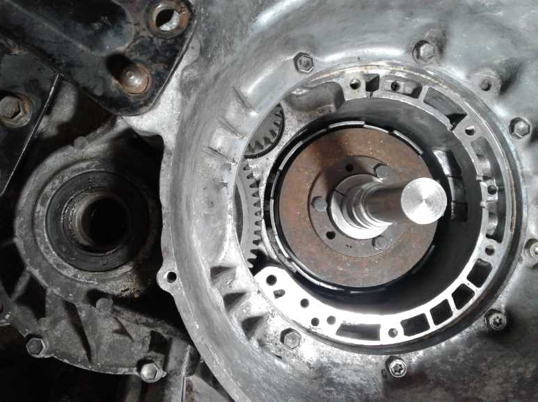
 The emptied-out back (left, port) end of the
transmission.
The emptied-out back (left, port) end of the
transmission.
Splined shaft, ball bearing, and clutch plates.
Squeezed together, the clutch is solid in the housing.
Loose, the rings spin around (making heat and wasting energy).
(The ring gear fits on the rear center spline, turns with the center
shaft.
Oops, no picture.)
 It holds the planets assembly and keeps it from
spinning.
It holds the planets assembly and keeps it from
spinning.
...or lets it spin. I wanted it locked, in both directions.
(The planets mesh on the outside with the unseen ring gear.)
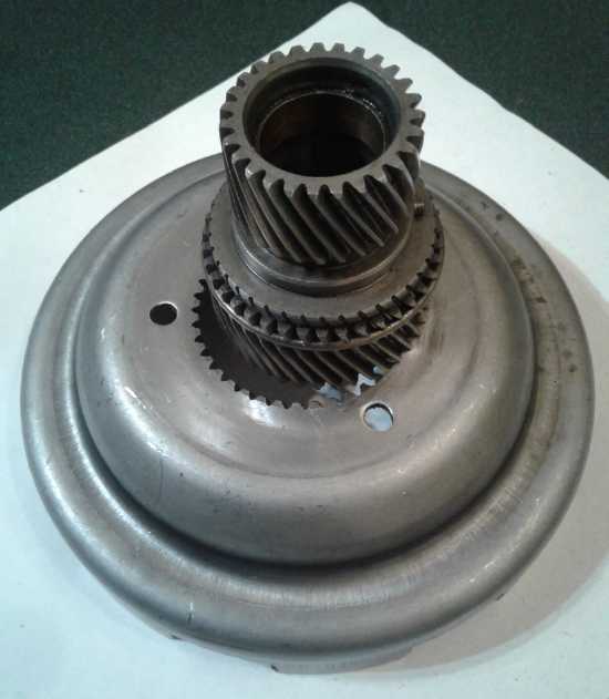 The small end of the double sun gear meshes
with the planets.
The small end of the double sun gear meshes
with the planets.
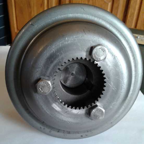
To turn this gear, the big "drum" or "plate" fits onto the
large end gear.
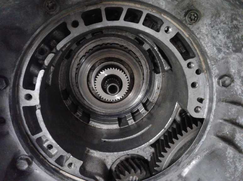 Whole planetary gear in, without drum.
Turning the sun gear gives ~8.9:1 reduction ratio to wheels.
 I noticed that an SDS or SD shaft hub would fit
in the drum and the 3 holes almost lined up.
I noticed that an SDS or SD shaft hub would fit
in the drum and the 3 holes almost lined up.
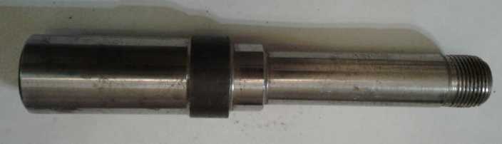 ...and a trailer stub axle was just right to
make into a shaft with the SD hub.
...and a trailer stub axle was just right to
make into a shaft with the SD hub.
 Shaft turned to diameter and all fitted.
 I drilled and tapped the large holes in the hub
to 3/8" threaded.
I drilled and tapped the large holes in the hub
to 3/8" threaded.
I filed out the holes in the drum to match.
I used 1/2 coupling nuts, machined flat and drilled out a bit
as spacers/standoffs to get the SD hub higher up.
(I think the drum would bend before they would tilt over.)
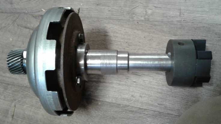 Complete shaft, with a pulley just to compress
the SD hub.
Complete shaft, with a pulley just to compress
the SD hub.
Lovejoy (L099) coupler to attach to motor.
(Shaft is keyed at both ends to hold fittings without slipping)
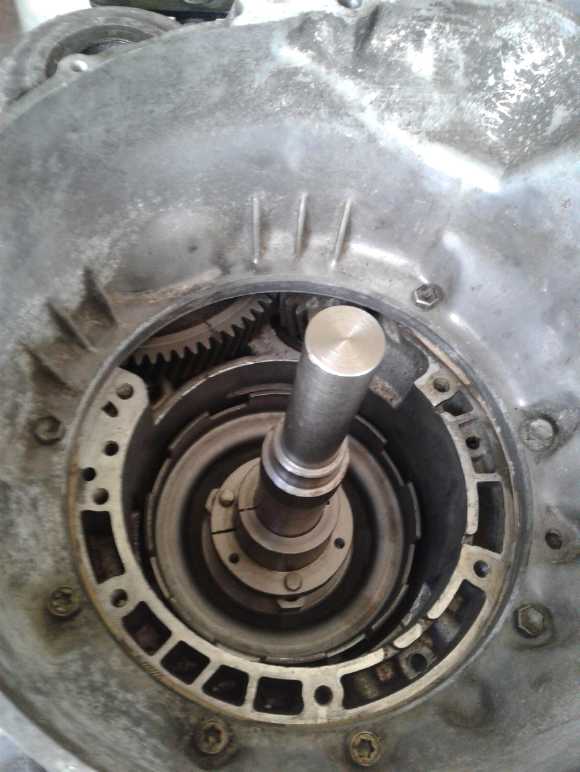
 Final arrangement fitted in.
Being able to switch gears to 4 to 1 at higher speeds
sounded useful for the highway in theory, but the first problem was
that it would be hard to accomplish without reassembling the whole
transmission and putting all the crap back in. That was out. Second,
some sort of shift lever for the driver would have to be (re)installed
- more extra work. Finally, and most convincingly, just going through
the planetary gear, the reversing gear set and the final reduction at
the differential, the unit turned quite freely. It was probably better
than the rather small diameter gears in the manual transmission. But if
the clutch with its several plates was released and slipping, one could
feel substantial friction, and there would be more of it with fluid
friction at speed. Here was at least one reason why automatic
transmissions (assuming others are similar) are so inefficient and get
so hot they need to run their oil through the car's radiator to cool
it. Such losses would decrease the driving range substantially, so it
would be better just to run the electric motor faster and forget the 4
to 1 idea! (Another lossy part that drops the range substantially in an
automatic is the fluid "torque converter". I ditched that long ago.)
Owing to the known notoriously high losses of automatic
transmissions, my prejudice against them was such that I hadn't looked
into them until recently, to discover that there are some fine parts in
there at the back, if only you can figure out how to pull out and get
rid of, or disable, the others.
It's not impossible I could have used the internal clutch
and put some sort of flywheel on my shaft, but with 8.9 to 1 reduction
that arrangement seemed superfluous. I tried to find a way to press the
plates together to lock up that clutch. There was a whole assembly that
went underneath inside the oil pan, where the explanation of how it was
normally done probably lay. Maybe hydraulic, or a solenoid, or both. I
didn't want to get into it. I tried putting in an extra circlip ring
under the one holding the clutch pieces in. It went in but the clutch
was still loose. A second one wouldn't fit. Finally I "crinkled up" one
of them just a little - made it wavy up and down - and managed to work
it in it under. I counted on its spring action to push the plates
together. After that I couldn't get the assembly to turn even by prying
it quite hard with a screwdriver. I trust that will work. The entire
essence of the transmission was now one reducing planetary gear, large
and equal size reversing gears (worthless extra!) and the differential
with its reduction, altogether a highly efficient 8.9 to 1 reduction
from motor to wheel shafts!
This time I decided to leave it off the car until I had
the motor mountings figured out and fitted. Inspecting and figuring
everything out, then getting it assembled as desired and the bottom
closed up again, about killed the day.
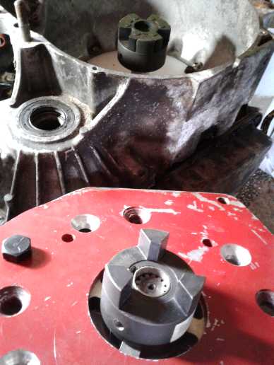
But then I thought about the next problem, connecting the
motor, and about there being just one bearing on the motor, and I went
out before supper to check it out. I took 3 bearings over to the motor,
and discovered to my surprise that a common 1" cup and cone ("trailer
wheel") roller bearing fit perfectly. The 7/8" splined shaft had a 1.0"
shoulder sticking out just far enough to catch the center hole, and the
outer recess was exactly the diameter for the cup. Somebody must have
thought of allowing for possible uses needing two bearings when they
designed the motor!
The 3 holes in the drum-plate that fit onto the double sun
gear reminded me of SDS bushing holes. Before bed, I went back out to
the shop and brought in an SDS bushing. They were close enough that it
would be just a matter of filing the holes outward on the plate. Then
it just needed some kind of ring for a spacer to get it past the inside
shaft, and a chunk of metal (washer) to compress the SDS bushing so it
would latch onto a 1" shaft to the motor. (And bolts of course.)
It was starting to feel like progress.
That left:
- coupling the shaft to the double sun gear. (per above)
- the bearing on the motor shaft at the business end. (per above)
- that splined shaft on the motor with no matching socket, to
connect to my 1" shaft.
- the mismatched center hole size & bolt holes between the
motor and the motor mounting plate.
- and the plate that had to seal the oil in in the middle of the
shaft.
Motor Bearing
I was otherwise occupied on the 11th but on the 12th I put
the bearing cup into the motor end. It wouldn't go all the way down but
seemed to definitely stop about .1" above the apparent stop point. This
also meant the cone didn't quite go down to the 1" diameter part. That
just means I'll have to make a spacer to fill the gap between the 1" ID
of the bearing and the ~13/16" OD of the motor's splined shaft.
The next day I managed to pry it out, and I scraped the
hole out a bit and (noting a little rust or crud on the outside) got a
new bearing cup. This time it went a little farther, but it didn't go
in straight. I finally got out a micrometer and measured that the low
end was over a millimeter below the high point. I started pounding with
a hammer on a big screwdriver on the high areas. They went down, 1/10th
of a millimeter each time after a bunch of pounding. Finally they were
within 1/2 mm and I gave up. I would hate to try getting it off now!
Now the cone contacted the 1" part of the shaft. A little. A spacer for
the rest wouldn't hurt. And something'll have to keep the cone from
coming up from the cup.
Shaft Coupler (to motor)
On the morning of the 14th I thought of Lovejoy "jaw"
flexible couplings. These fit onto a shaft and are (in "L099" size)
about 2.5" OD. Around the rim on one face they have three triangle
blocks and 3 triangular spaces between. The spaces are bigger than the
bumps, and a rubber "spider" piece with 6 lobes fits on, leaving the
holes the size of the triangles so the other identical piece fits right
on with rubber padding between the two shaft couplers. These are quite
common. If any sort of socket would be available for the splined shaft,
it would be a Lovejoy coupler. It could be solidly affixed to the shaft
to hold the bearing cone in place, while allowing the motor to
"automatically" couple itself to the shaft inside the housing as its
mounting plate is maneuvered into place.
If I couldn't find one with the right spline center,
perhaps I could get one with a 3/4" round center and mill 13 semi-round
slits into the edges of the center hole, to roughly make matching
splines so it would fit? Well, that sounded like a suspiciously easy
way to break small diameter end mills to make something that wouldn't
work out well. Better if I could find the right one to buy. I found
lovejoy-inc.com and they had a catalog which included one with a 13
spline center that sounded right. I decided to get one and left it with
the local auto parts store on the 15th.
The center hole for the mating Lovejoy coupler on the 1"
shaft side would of course be simply 1" round, with a 1/4" square key
slot. I already had one of those, plus the 6-legged rubber "spider"
that went between them. (I thought spiders had 8 legs!)
Shaft Connection to Transmission
Things get complicated when you want to do anything with
machine parts that isn't just how they were intended to be used. In
this case, (with the transmission up-ended) the one end of the double
sun gear normally from the "upper" planetary gear drove the other end,
the sun of the "lower" planetary gear. Seemingly this is the usual
configuration in an automatic transmission. Now there was only the
lower planetary and I had to connect a shaft to drive this double gear
directly. There wasn't much to attach it to. But there was the "drum"
piece that locked onto the upper sun, which was bigger and made of
steel 'plate' or 'sheet' rather than 'cast and case hardened', which
meant it could be drilled to attach bolts to. If that turned, the gear
turned.
As a further complication, the ~3/4" center shaft sticking
out from the back of the transmission protruded 1.13" above the top of
the upper end of the double sun gear. It was intended to mount upper
planetary gear parts on, but now it simply prevented anything with a
solid center from being mounted flat on the top end of the suns.
Theoretically I could cut off the extra length, but it was one piece I
hadn't been able to remove from the case. I couldn't get the angle
grinder in there near the bottom/back except at a steep angle, and even
if I did crudely cut it anyway, it was almost certain to leave bits of
case hardened steel filings inside to get caught in and jam or damage
the gear teeth. That might wreck everything.
On looking for a 1.0" ID "SDS" taper lock shaft bushing, I
ran into my only "SD" bushing, a similar longer bore version. Sitting
on the gear, the top stuck up .75" beyond the top of the offending
shaft. So, a shaft with a key slot could be clamped into it with its
end just above the shaft. The drum holes could be filed out, and the
three larger holes in the SD could be threaded, to take reasonably
hefty 3/8" bolts to bolt the SD to the drum leaving space for the gear.
The trouble was I only had the one SD bushing, and it was
1-3/8" ID. I didn't have a shaft larger than 1.0"... or did I? At one
time I had purchased some trailer wheel stub axles on line. They were
1.40" OD at one end, while the other end was 1.0" threaded for a nut
(typical trailer wheel axle). By turning the fat end down just a tiny
amount, it would fit in the 1-3/8" SD bushing. (1.40" => 1.375")
Furthermore, with the wide part just wide enough to stop it, it
couldn't "ride down" into the bushing to contact and rub on the
obnoxious protruding axle. The threaded end could be cut off, leaving
plain 1.0" shaft, which would then get a 1/4" key slot milled into it.
This would fit the Lovejoy coupler. It would also leave the shaft quite
close to the desired length.
If the shaft was still a little too long (probably), the
center of the fat end could be bored out for the required distance (so
it would fit around the annoying center shaft without touching it) and
the "trimmed" outside portion lengthened to slide it a little further
into the SD bushing (even better).
That left the fact that the middle of this shaft has to
stick through the sealing wall. Here again this particular shaft has
the advantage of having one area turned the correct diameter to mount a
standard trailer axle seal. Even if it wasn't in the right place, the
thicker shaft could be turned down to extend that seal-diameter area so
the seal could be affixed to the wall and allow the shaft to turn while
keeping the oil inside.
So it looked like the 1-3/8" SD bushing, with the trailer
axle shaft, would in fact be pretty much ideal. The only concerns would
be that the SD couldn't be solidly centered, that the 3/8" bolts would
best be reinforced to keep them from twisting with torque, and that
they had better not come loose. Probably the first two concerns were
"good enough" if I couldn't fit in a piece(s) of something to make it
better. For the last one - if there were no other pieces inserted - it
looked like lock nuts could probably be placed between the components
and tightened against the drum (last) as a precaution. (That would
require bolts with threads running their whole length.) Hmm... could
coupling nuts be useful to reinforce the bolts?
On the 16th I cut the threaded end of the shaft off,
turned the 3/4" long space on the fat end to 1.375" OD to fit in the SD
bushing, and threaded the SD bushing's three larger mounting holes for
3/8" bolts. I decided to use 1/2" coupling nuts, cut to length, as
spacers and "shoulders" on the 3/8" bolts. It'd be stronger, and they'd
fit unthreaded, like very, very thick washers.
On the 17th I cut two 1/2" coupling nuts in half to get 3
the length I wanted, then I turned them on the lathe so the ends were
"perfectly" square and flat and all 3 were about the same length on the
micrometer - about 20 mm. Then I filed out the holes in the drum/plate
so they exactly accommodated 3/8" bolts and also centered the SD
coupler and shaft as best I could get them - within 1/2 mm or so.
Filing took a lot of time but I wanted the holes positioned and sized
accurately. The whole assembly just drops down over the upper sun gear,
and there's some tolerance for imperfections. I had to drill out the
threads of the 1/2" coupling nut shoulders a bit so they could be moved
outward a bit so as to not jam against the gear. But having them all
touching the center gear will further help ensure the SD stays centered.
I put it together and it all fit and turned. The coupling
nut reinforcements and the arrangement in general looked strong enough
to handle any plausible amount of torque.
The lock washers were a little bigger than the bolt heads
and jammed against the gear, plus the bit of extra length caused the
bolt heads to rub on the piece below. I had to take them off. I'm not
usually a fan of "Locktite", but I think I should get some, because if
those bolts come loose things will jam up and probably cause damage.
Not to mention one might get stranded by the roadside and need a
front-wheels-lifted tow.
On the 18th I braved the 3°C shop again. I bored out
the center of the shaft so it would fit right over the offending center
shaft no matter how far down it was, and turned out another 1+" to the
1.375" OD so it fit down along the entire length of the SD bushing. (I
could see that the shaft was a bit too long anyway. After this it was
probably about perfect and the seal-diameter area was in the right
place.)
Mounting & Attaching the Motor
(18th) At first I thought to bite the biscuit and grind
out the center hole in the coupling plate to fit the motor flat on the
plate. (I'd rather have a giant lathe and turn it out carefully and
neatly, but I don't. It would also be a good case for having the CNC
drivers attached to the milling machine, since milling around a good
circle by hand would be almost impossible but easy with CNC. Then
driver software would have to be set up. Not today!)
Then I decided to try with the plate "as-is". Once the
bolt holes are drilled, they're in the right place either way, so the
center could be ground out later if it seemed necessary or desirable.
But with the Lovejoy couplers there's a margin for slight
misalignments, and for the shafts not being ideally close together, so
whatever way it's done should be okay.
With no results from the auto parts store, I spent my
available hours on the 19th on line trying to find a suitable Lovejoy
Jaw coupling. Much of the time was waiting for complex pages to load
over the slow internet. I finally had to order both ends of a somewhat
larger "L110" coupling size (instead of "L099", which I had one of for
the 1" shaft) because someone had some on e-bay including the 7/8"
spline center for the forklift motor. But I had to order the matching
"spider" to connect them together from China. It may arrive after
everything else is finished.
On the 20th I drilled the bolt holes in the plate to mount
the motor. On the 21st I went into town and got rare 9/16" bolts.
(Actually the motor's bolt holes were tapered and I had to drill the
small end out just a bit, and then likewise increase the plate hole
size, after I got the bolts. But 1/2" bolts would have been a sloppy
fit.) As I had made the holes carefully with a drill press, there was
no play and the bolts couldn't wobble at all. In fact I had to hammer
one to get its shank started into the hole. This snug fit is desirable
so reversing the motor can't twist it back and forth a little, making
the bolts work looser and looser.
On the 22nd I milled out a keyway in each end of the shaft
for the transmission to make it move the car instead of probably
slipping. At this point the link between the motor and the mostly empty
transmission was completed except for the arrival and installation of
the Lovejoy coupler parts.
Oil Seal
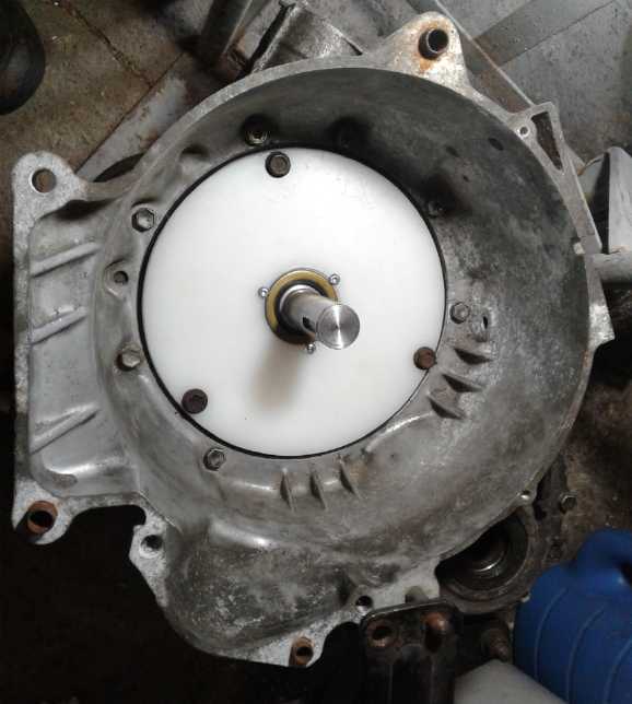 On the 23rd I
tackled the plastic plate to seal the oil
filled part of the transmission from the outside. (Some years back, not
expecting to ever use the transmission, I had carelessly thrown out the
original metal part.) The center hole had to be enlarged on the lathe
so the shaft fit (loosely) through it, with a still larger recess part
way through to hold a bearing seal. Then the shaft could pass through
the wall via the seal without the oil leaking out. My lathe was too
small to hold the plate except in its "gap" area. I had to make a jig
to hold it on in that position as nothing fit and I didn't want to
drill bolt holes through it. After trying various fits, I turned a 1/2"
nut down to fit as if it was a short piece of shaft just at the end of
the lathe's #2 Morse taper main spindle. Through the spindle I inserted
a 1/2" threaded rod, and threaded it through the special nut, which
held the rod centered. Another nut on the rod's outside end clamped it
all securely. That made a 1/2" threaded spindle - the size of the
center hole in the plate. I also put on a metal backing plate (lathe
attachment) to hold it all square, but with no bolts into that plate. A
third nut held the plate on the rod and against the backing plate.
On the 23rd I
tackled the plastic plate to seal the oil
filled part of the transmission from the outside. (Some years back, not
expecting to ever use the transmission, I had carelessly thrown out the
original metal part.) The center hole had to be enlarged on the lathe
so the shaft fit (loosely) through it, with a still larger recess part
way through to hold a bearing seal. Then the shaft could pass through
the wall via the seal without the oil leaking out. My lathe was too
small to hold the plate except in its "gap" area. I had to make a jig
to hold it on in that position as nothing fit and I didn't want to
drill bolt holes through it. After trying various fits, I turned a 1/2"
nut down to fit as if it was a short piece of shaft just at the end of
the lathe's #2 Morse taper main spindle. Through the spindle I inserted
a 1/2" threaded rod, and threaded it through the special nut, which
held the rod centered. Another nut on the rod's outside end clamped it
all securely. That made a 1/2" threaded spindle - the size of the
center hole in the plate. I also put on a metal backing plate (lathe
attachment) to hold it all square, but with no bolts into that plate. A
third nut held the plate on the rod and against the backing plate.
I made the recess for the seal with a boring bar, then
with the bar virtually touching the nut, I pushed it all the way
through to broaden the center hole. This would only have worked in
plastic, as I was really abusing the boring bar which had no real
cutting surface on the inside edge. The hole came out tapered, oddly
narrowing as it went in. I would have thought it would widen, since the
carbide cutter was there. And anyway how could it do anything but go
straight through? Something must have been loose.
The tapered hole was too small for the shaft at the small
end. How does one widen a piece of UHMW? To make a long story short I
ended up with a straight router bit on the drill press, and worked the
plate around by hand until enough material had been removed.
To make another long story short, I drilled three holes
around the outside for mounting bolts where 3 of the 5 threaded holes
were in the transmission, at approximately but not exactly 120°.
They should be quite sufficient.
I quit for the day to get supper, without having decided
what to use for a fat gasket around the outside slightly small outside
rim, but with everything fitting together properly. I finished the next
morning (24th), winding half a roll of vinyl ('electrical') tape around
the outside for a gasket. When the fit seemed about right, I put it in
and put the bolts on. The transmission was ready to install.
The motor still needed spacers to ensure alignment of the
bearing with the shaft. In the evening I made one, and an extra one to
hold a 1" Lovejoy connector as best it could onto the 7/8" spline on
the motor. That way, if it could be induced not to slip, I could test
out some basic functionality, ie, see how the motor moved the car in
the garage and maybe outside and what voltage it took to do it.
I also started looking into getting a motor controller and
requested a quote. It seemed pointless to deign and make a primitive
controller when I was only doing one such conversion (maybe 2... maybe
I'll get another forklift motor to do the Toyota Echo?). I might as
well buy one with good features. I selected a Curtis 1243-4320
"separately excited [DC] motor" controller (36 volts 350 amps) plus a
Curtis programmer. The controller switches the field coils including
for doing forward and reverse with less than 10% of the current
required to switch the armature coils.
At first I was concerned about the controller's "36 volts"
voltage rating and thought I'd need a higher voltage one. With
electronic components the rating is usually the absolute maximum before
it blows up, and you want to stay well under it. But the manual said it
starts limiting if it hits about 45 volts, so it should be able to take
battery "nominal" 36 volts, ie, anything under about 44 during charging
("max" with 12 lithium cells) and less than 42 when underway, fine. And
hopefully the hand-held programmer will work for the two Curtis AC
motor controllers I have, too - in the Miles truck and from the Swift.
 On the 25th I
cludged a 1" shaft Lovejoy connector onto the motor's splined shaft
with a spacer tube and set screws. This also held the bearing cone in
place. Then I (finally) ran the motor, using 4 lithium cells in series
to get 3.2, 6.4, 9.6 or 12.8 volts. One clamp-on DC ampmeter said it
drew about 18 amps, the other said 15. (Huh? Not the sort of
discrepancy one expects from pricey modern digital test equipment!)
This current was regardless of the voltage, but it turned faster as the
voltage was increased. Current and torque are proportional. Watts is
volts times amps - or torque times RPM - so the power went up pretty
much linearly with voltage.
On the 25th I
cludged a 1" shaft Lovejoy connector onto the motor's splined shaft
with a spacer tube and set screws. This also held the bearing cone in
place. Then I (finally) ran the motor, using 4 lithium cells in series
to get 3.2, 6.4, 9.6 or 12.8 volts. One clamp-on DC ampmeter said it
drew about 18 amps, the other said 15. (Huh? Not the sort of
discrepancy one expects from pricey modern digital test equipment!)
This current was regardless of the voltage, but it turned faster as the
voltage was increased. Current and torque are proportional. Watts is
volts times amps - or torque times RPM - so the power went up pretty
much linearly with voltage.
 Then I fitted it onto the
transmission, still standing on
end in the garage. After a couple of adjustments and temporarily
removing a mounting bracket that was in the way it turned freely and I
brought out the battery and jumper cables. This time it wouldn't start
turning at 3.2 volts (so much for "no" friction in the transmission),
but at any higher voltage it turned freely. At 12.8 volts it took
almost 2 full seconds to come to a stop after the power was removed, so
it must have been turning pretty freely. (Rats, I neglected to check
the currents.)
Then I fitted it onto the
transmission, still standing on
end in the garage. After a couple of adjustments and temporarily
removing a mounting bracket that was in the way it turned freely and I
brought out the battery and jumper cables. This time it wouldn't start
turning at 3.2 volts (so much for "no" friction in the transmission),
but at any higher voltage it turned freely. At 12.8 volts it took
almost 2 full seconds to come to a stop after the power was removed, so
it must have been turning pretty freely. (Rats, I neglected to check
the currents.)
Then I installed the transmission in the car. (I guess it
needs some oil now. Where do you fill it?) Then I attached the motor.
With no mountings on the starboard side, it all hung down. Regardless I
hooked up the jumper cables and tried it out. Assuming nominal voltages
(probably not completely accounting for voltage drop at high currents),
and the meter that read currents as being lower than the other, gave
these results:
3 V - no movement (on level cement), 15 amps
6 V - backed up very slowly on level, stopped on slight up
grade, 60(?) amps (360 W)
9 V - backed up slowly including up slope, 75 amps (675 W)
12 V - backed up faster and up the slope, 77 amps (924 W)
Some Conclusions
Smooth! Silent! I'm pretty sure the high 8.9 reduction
ratio was the right one, and that 4 to 1 wouldn't have worked out well.
At 8.9 the forklift motor seems to have the torque to move the car
nicely, and at 36 volts presumably sufficient power for the road. There
are some performance unknowns and it's a pretty small motor. I expect I
have the makings of a nice car for in town, but I have my doubts it
will prove practical for highway driving as now configured. If I
crossed a wire it would go forward. (I'll let the 1243-4320 motor
controller and a forward-reverse switch handle that when things are
farther along.)
If all that seemed like pretty slow progress, I must say
it's surprising how much time can be spent on precisely machining and
drilling special parts (and in a shop that's really too cold to be
working in). And trying to find and purchase uncommon things over a
slow internet. And driving 25 Km each way to town and back to buy
anything "locally". And I had other things to do most days which
couldn't be put off and ate a lot of time.
And that would be more or less it for February. I could
work away casually at cleaning up the car while I awaited the proper
Lovejoy shaft couplers and the motor controller kit. It's time to start
spring garden seedlings.
Apparently I wasn't ready to do something else after
all... here's the diary to the end of the month:
26th: Connected speedometer. (pulled out and greased the cable.)
Cleaned crap off seats and floor.
27th: Bought gear oil and filled transmission. (Doesn't seem
to leak, but the real test will be on the road.) Vacuumed and
cleaned car. Ceiling was all mildew but it seemed to come off okay with
a soapy cloth. Removed gear shift lever. Now there's a hole in the
floor! When I tried to run the car back into the garage, the motor
turned but the car didn't move. The parking brake was on. The motor
must have broken loose the set screws connection. I hope the spline
shaft isn't gouged.
As of this day a pricey L110 spider is coming from
Victoria and the order is paid for the Curtis 1243-4320 motor
controller, 2 16 pin Molex connectors to connect all the stuff to the
controller, and Curtis 1313K-1313 programmer for their controllers -
which I hope will also do the Curtic AC motor controller in the Miles
truck and the one from the Swift (still available for the ground effect
craft). This was over 1000$C, and 2/3 of it is for the programmer. If I
hadn't wanted that it wouldn't have been so bad. This project is
starting to get costly!
28th: I'm pretty sure this car was originally a "Key2Parts" auto
parts delivery vehicle in Victoria. I had seen a young lady flying
around in it the early 1990s and said to myself "Hey, that's the same 3
cylinder engine car I almost bought new in 1986 for 5995$." The 2 door
version reputedly got 40 MPG in town and 50+ on the highway. I think
Suzuki (it may have been their first car) blindsided the oligarchs that
control everything, and they had to work over the next few years to get
the manufacturers to change it to 4 cylinders, larger wheels, rename it
the "Geo Metro" and get the gas mileage down to "nothing special here".
Where was I going with all this? Oh yes... the rear side
windows all had tinted films on them so the car parts inside weren't
readily visible during deliveries. I could have peeled these off pretty
easily when I bought the car. (I think I remember peeling one off the
rear window when I bought it.) Instead, they had deteriorated in the
sun and weather over the years. When I moved I stuffed the electric
vehicles full of stuff. The wire fencing in the Sprint had scratched up
the window films, so now I definitely had to scrape these flakey but
well glued flims off with a "razor blade" (chisel blade in an Xacto
knife), bit by bit. The right side which had been facing north was much
easier than the sunny south facing left - it still peeled off in
sections. That annoying little job polished off February!
I also was puzzling over how to support the right
(starboard) side of the assembly, which hung down at an angle. The
tranny was supported and stabilized at the left and middle, but there
was no engine reaching over to the right hand support. And it was far
enough over that it was almost horizontal to the tranny, so a simple
bar between them wasn't going to offer much support. There was nothing
to attach to on the motor, which was anyway still only marginally below
the support. I didn't see a good place to weld another support onto the
frame. What to do?
At this point, how much of this project was innovation and
how much was just a "regular" if somewhat unique electric
conversion? The transmission losses should be quite low but the
motor was pretty ordinary. So surely I couldn't expect it to give much
extra driving range over other types with the same battery capacity. I
did set out to use a lower voltage than most conversions for more
flexibility in battery configurations and perhaps solar panels on the
roof for direct trickle charging, and the 36 volt motor allowed for
that. But if I once had it running nicely (hopefully on the road), I
would like to go back to designing motors and try to make a better,
permanent magnet assisted reluctance motor and the unipolar controller.
That type could easily do 10000 RPM for the highway, making a fixed
ratio practical for all speeds. And somewhere in the "PM assisted"
motor formula is that elusive 500 mile driving range!
RPM Calcs
What horrendous RPM would the motor be doing at 100 Km/Hr
with 8.9 to 1 reduction?
100,000 meters/hour / 60 minutes/hour = 1667 meters/minute
~20 inch effective tire diameter * .0254 meters/inch * pi = 1.60
meters circumference
1667 meters/minute / 1.6 meters/revolution = 1044 RPM
1044 RPM (tire & wheel) * 8.9 = 9292 RPM (motor)
Hmm, around 9300 RPM at 100 Km/Hr. It's the usual problem that
having enough reduction to start the car moving makes the RPM very high
on the highway. What was it capable of? The label read:
Advanced D.C. Motors Inc.
Part Number 2798905.
36 volts DC
Rating: AU260... maybe another 0... or 6 or 8... and the rest was
illegible, corroded away. "RPM", "amps" and "watts" or "volt-amps"
would have been nicer figures to see. I suppose I should try looking up
"AU2600".
I couldn't find any specs on line, but in an old EV
discussion forum forklift motor ratings like 3500 RPM and 5000 were
mentioned. They were mostly talking about somewhat larger diameter
motors than mine (80 to 150 pounds versus 51). Perhaps I might push my
smaller one to say 6500 RPM? Maybe! (That might take 48 or more volts,
too?) That's about 70 Km/Hr. Well, it might be a good town car if one
can avoid the highway. Not exactly a replacement for the Nissan Leaf!
Unless it would do about 9000 RPM nicely. Also with such a small motor
it might not have much "oompf" on the highway anyway, and higher RPMs
will give it more in town. Well, it's probably about the best I'll be
able to do with what I have. The DIY EV forum mentioned using a blower
to cool smaller motors. Somehow I still have the Sprint's radiator fan!
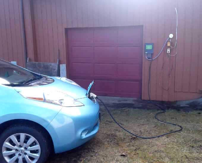
J1772 EV
Charging Station
With a Nissan
Leaf coming, in January I got a J1772 240 volt, 15 amp EV charger
bought used from someone in Seattle. (Tom had ordered it - and then
moved away.) I had also ordered a 30 amp one from Home Depot at the end
of December, but it hadn't shown up, and at the end of January I asked
for a got a refund. I had also decided that the 15 amp charge would
help the batteries last longest, instead of driving charge more rapidly
into them.
On the 5th I broke up a piece of 3/8" particle board
(remember that crap from the 1980s?) wall in the shop and on the 6th I
ran wiring. By luck there was already a spare double 15 amp breaker in
the shop sub panel. I ran another wire at the same time for a 120 volt
outlet next to outside the shop and garage, which I've been wanting
since I moved here. The charger worked fine. (I found the right
("Stablok") circuit breaker for the outlet and it also worked fine.)
The next morning (7th) I found the 30 amp charger from
Home Depot on my doorstep, dropped off by UPS while I was out. I hadn't
expected it and hadn't wanted to take delivery of it. (I got it sent
back a few days later.)
In Masset that day I bought two weatherproof(?) electrical
boxes. Now that it's working, just when I'll get around to finishing
the job... changing out the first (octagon) box...
protecting the unarmored cables... ripping off the rest of the
shattered wall
board (recessed behind the ceiling at the top - ugh!) and replacing the
wall over the sub panel and door (with gyproc, screwed on for easy
removal instead of crapboard with dozens of sunk-in nails!)... was in
the
lap of the gods.
Other
"Green" Electric Equipment Projects
Indoor
Vegetable
Growing With LED Lights
 I bought five cheap "over the
mirror" four-bulb fixtures and two boxes of twentyfour 8.5 W LED light
"bulbs" at Lowe's in Victoria over Christmas. I threw away the
decorative parts of the fixtures, added a 30 watt, 6000 K, 30 cm x 60
cm, LED flat panel light, and made a "table" frame with 200 W of LED
lights shining down. The idea was to put pots of vegetables underneath
either as bedding plants, or even to grow them to edible right there.
I bought five cheap "over the
mirror" four-bulb fixtures and two boxes of twentyfour 8.5 W LED light
"bulbs" at Lowe's in Victoria over Christmas. I threw away the
decorative parts of the fixtures, added a 30 watt, 6000 K, 30 cm x 60
cm, LED flat panel light, and made a "table" frame with 200 W of LED
lights shining down. The idea was to put pots of vegetables underneath
either as bedding plants, or even to grow them to edible right there.
The idea of making or finding LED lights with just the
right light wavelengths that plants use (~430 nm violet and 660 nm red)
was appealing, but it was far easier to get lots of LIGHT this way. And
that's what plants need. Sunlight has about 100 watts per square foot,
and if this lit 2x5=10 square feet, that was only 20 W/sq.ft. But
brighter than most artificial lighting setups.
The lettuce pots
on February 18th
To this idea I added rolling "dollies" to put the pots on.
That way, the plants could be rolled out from under the low table to
water, weed and harvest. I started some leaf lettuce near the end of
January in little plastic seedling planters and soon transferred them
to a big box. They were pretty wimpy looking, but are growing and now
need thinning. (They're a bit yellowish-green - may need calcium/lime.
...or ???) In mid February I planted some 'romaine' style lettuce in
another box. Instead of pots with holes at the bottom and a tray around
them to catch the escaping water, I put two cans in the center of each
box, a well with no dirt to the bottom, so you could see if it was too
wet, and also pour water and liquid nutrients (nitrogen from...) into
the hole instead of onto the plants.
Some mold started growing in the dirt, and I remembered
hearing that ventilation was vital in greenhouses. That seemed to apply
here and I put a quiet little computer fan on top blowing down through
a hole, and ran it off 6 volts of NiMH cells in a tube. At that voltage
it was inaudible unless you put your ear right up to it. The mold went
away. But it'll need higher speed or (better) two fans as I add
planters.
I put some old tomato seeds (two types) in a pot in the
last week, but none came up. Seeds several years old can be a waste of
time for many species. It wasn't until the end of February I started
getting some more going and lit the 70 watt section (3 rows of 4
'bulbs') at the right end of the table. (I should have started planting
earlier with this great light advantage, but I was too busy with the
car project to get out the seeds and decide what to plant. I should
have planted some spinach and less lettuce.)
I'll be using some lettuce leaves in my next salad as it
needs thinning.
The grow-op on February 28th.
Both lettuce boxes are now on one 'dolly'.
(I now have enough castor wheels for a third dolly, but it'll have to
be narrower.)
No hedge laurel bushes came up from pits from 4 year frozen berries,
and no tomatos from old seeds came up in the big pot - Rats!
seedling trays ready for planting.
Electricity
Storage
Nickel-Nickel
with Oxalate Battery Chemie
Electrolyte Experiment
Having obtained potassium oxalate and having made ethaline
DES, the obvious next step was to try them. Theoretically the DES was a
replacement for water, the medium of the electrolyte but not an
intended participant in the reactions. I put in a cupro-nickel sheet
("-") and a separator paper. On top of this I sprinkled a little of the
baked nickel-lanthanum-thiamin powder that I made long ago for some
nickel oxide subtance (+), and put another sheet of cupro-nickel on top.
Then I poured in a little DES to wet the separator paper.
I hooked up the new power supply and set it to 1.6 volts. No current
flowed. That meant no ions were flowing between the electrodes, so the
DES was acting like pure water. It needed a salt to become an
electrolyte. That seemed promising.
Then I sprinkled in a gram of potassium oxalate. The
current went up to about 120 mA and gradually (minutes) dropped to 50
mA. It seemed to keep charging, the current kept dropping but the
voltage didn't stay up.
(The metering in the new power supply is crap. The supply works fine,
but I had expected auto-ranging on the current reading. Not only was it
stuck on X.XX amps scale, but it either read 0.03 amps or 0.00 -
nothing in between! And it takes a while to see the current after
switching from reading voltage. Maybe I'll try some other make and
model.)
This was near the start of February. Then I got into the
Sprint car project and everything else stopped. My only note after that
is that ethaline DES stinks. I put the cell in a semi-sealed plastic
food tub.
http://www.TurquoiseEnergy.com
Haida Gwaii, BC Canada