Turquoise Energy Ltd. News #118
covering March
2018 (Posted April 3rd)
Lawnhill BC Canada
by Craig Carmichael
www.TurquoiseEnergy.com
= www.ElectricCaik.com
= www.ElectricHubcap.com
= www.ElectricWeel.com
Month
In Brief
(Project Summaries etc.)
Special Feature:
The Fantasy Budget!
What if someone offered me a fortune for the purpose of helping to
improve the world?
In
Passing
(Miscellaneous topics, editorial comments & opinionated rants)
- The need for teaching the core values of social sustainability
- Inbread humour?
- Project Reports
-
Electric
Transport - Electric Hubcap Motor Systems
* Chevy Sprint: Battery placement - Motor Controller
* A BLDC Motor Disassembly
Other "Green"
Electric Equipment Projects
* Carmichael Mill ("Bandsaw Alaska Mill")
* "The Indoor Vegetable Garden" -
Year round gardening with LED Lights!
(and other gardening)
* LED Light Making Update (how the ones I made some years ago are
faring now - dimming - repairs)
Electricity Generation
* Small Creek - And Larger - Hydro Power Units? - The spiral staircase "Turbine
Pipe"
with "Intake Head"
Electricity Storage -
Turquoise Battery
Project (NiMn, NiNi, O2-Ni), etc.
* Doped conductive coating separates graphite current collector
from electrode
* Ethaline DES with potassium oxalate and calcium hydroxide
electrolyte
* Nickel-Nickel test cell seems to work!
(real, practical cells for EV.s now seem possible)
* Use NO Graphite or conductive carbon black powder - It caused
the self discharge in all those previous cells
For this newsletter I've done something I should probably
have done quite some time ago as the newsletter length grew, and put
links from the table of contents to each section.
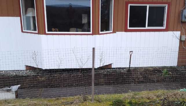 "reflective" white wall paint; blueberries and
strawberries planted
"reflective" white wall paint; blueberries and
strawberries planted
Whereas most of February was too cold to work out in the
shop, March got warm and sunny on many days and seemed ideal for
outdoor work and
gardening - so I still wasn't in the shop much and I didn't get the
bandsaw mill done. I picked away at the
Chevy Sprint electrifying project on many or most days (along
with yard work and other things), for some time mostly just figuring
out where the
batteries could go. And I wrote up a "dream budget"
so as not to be
caught by complete surprise just in case some wealthy philanthropist
should ask me how much was needed and what would be done if he gave me
some money to pursue groundbreaking projects and products in a big way.
Before mid month I was doing a lot of stuff outdoors and "project time"
continued to suffer.
Nevertheless, March saw some interesting and even exciting
developments.
- I thought up a new design, the turbine pipe, as a base
for flowing water hydro power production, especially for either small
creeks or floating hydro units.
- Jim Harrington and I had both been experimenting with growing
vegetables indoors with LED lighting. We had concentrated on the
lights. But now that I've been eating lettuce started in January and I
see what actually works and is needed, I started thinking it would be
ideal to offer a "complete solution" LED Indoor Garden. I
started to realize there's potential for selling literally millions of
them, so erstwhile indoor gardeners don't have to "re-invent the wheel"
to start growing their greens indoors in the winter.
- And then, the very occasional formulation and testing I've been
doing has at last apparently yielded nickel-nickel batteries that hold
a charge, with all the potential that holds for electric transport and
other battery uses.
These developments and other thoughts had me revising the
"fantasy budget" several times.
Carmichael Mill
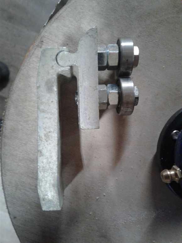 Along the way
I ran across some great parts I could adapt
for making adjustable band guides on the "bandsaw alaska mill", so the
band could be carefully aimed, adjusted with a thumb screw as required
to cut straight,
without removing the saw from the cut. They were a particular model of
pickup truck "canopy clamp" with a pivot hinge. I started adapting the
first one on the 11th then got sidetracked.
Along the way
I ran across some great parts I could adapt
for making adjustable band guides on the "bandsaw alaska mill", so the
band could be carefully aimed, adjusted with a thumb screw as required
to cut straight,
without removing the saw from the cut. They were a particular model of
pickup truck "canopy clamp" with a pivot hinge. I started adapting the
first one on the 11th then got sidetracked.
Small Creek... or larger... Hydro
Power Units?
I had puzzled at how one might extract electricity from
the
shallow creeks nearby, and I finally came up with an idea, and one
thought led to another. The final version was, Why have a floating unit
in such shallow
water?; use a screened funnel upstream entrance to keep crap out and
concentrate more water; that would feed an enclosed "turbine pipe" with
several
"spiral staircase" propellers along its length. Surely one could come
up with some sort of
small, portable low voltage unit, easily set into place in rapids on a
creek bed?
The (12 volt) power cord would be tied to a tree or
whatever
both for connection and to ensure the unit can't get washed away if it
comes
loose. Then it would be carried into the rapids and set down. Any
rocks holding it out of the water could be shifted, ideally setting it
down low, perhaps even forming something of a trench. Rocks could be
set on
flanges at the intake funnel, or on the pipe, to hold it in place, or
stakes pounded in. The steeper the pipe can be angled from intake to
outlet, the faster the flow will be, hence the deployment in "rapids"
or a fast flowing place.
Sticking to a very small, basic unit, this could be a
fairly quick and simple demo or an off-grid home power project.
Over the next days I thought of more and more variations
on the design. The generator could sit on top of the pipe, connected to
the shaft with pulleys or by a "U-joint" at 45°.
This configuration with the "turbine pipe" and a water
concentrating intake soon became the center of my thoughts for any
hydro power unit, small or floating, and whether the pipe was 4 inches
diameter by 3 feet long for a creek or 4 feet by 30 for a substantial
river. For a floating unit, the floats merely had to keep the pipe at
or near the surface and prevent it from spinning, making their design
and construction simple. (See the long
version under Electricity Generation.)
Chevy Sprint Electrification
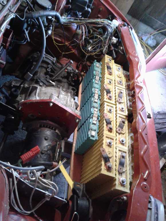 On this I
first figured out where to mount the batteries. I made a battery shelf
for 12 cells under the hood and a level styrene foam cushion for the
spare tire well for 24 cells in the rear. Then I did a "cargo floor" -
a cover over the batteries in the rear, and I set them in place and
(having two types of somewhat different shaped lithium ion cells)
figured out optimum positioning.
On this I
first figured out where to mount the batteries. I made a battery shelf
for 12 cells under the hood and a level styrene foam cushion for the
spare tire well for 24 cells in the rear. Then I did a "cargo floor" -
a cover over the batteries in the rear, and I set them in place and
(having two types of somewhat different shaped lithium ion cells)
figured out optimum positioning.
On the 21st the motor controller and programmer arrived
and I started wiring the controller up. I used the plate with circuit
breaker, contactor relay, car key relay et al that I had made for and
used with the Kelly controller, but I decided to put it inside the car
behind the firewall. That complicated things a little, but it won't get
road dust, water and de-icing salt in it! Then I turned it around for
better access and wire routing... and had to redo the heavy wires. In
the last two days of March I got it wired up and tried it. But
something isn't right, as the controller keeps shutting the power off
when I try to drive.
Nickel-Nickel Batteries
I found my old bottle of acetal ester and doped some with
osmium powder to try out for thin-film positive electrode current
collector coatings so the current collector substance (whatever may be
used?) wouldn't corrode away or cause self discharge, and painted it
onto the graphite foil. (If there are any gaps, at least graphite won't
corrode away like metal would.) I finally got the cell back together to
try it out on the 25th, which of course got me working on the project
again. After adding some more potassium oxalate and ethaline DES, it
seemed to hold a charge! And with a couple of other steps in the next
days, performance improved. But when I added some "conductive carbon
black" it started having the same nasty self discharge as my previous
cells. It was a graphic demonstration of the deleterious effect
graphite and carbon had been having on my cells. With the monel "solid
solution" mix it can work without the graphite. So, with the osmium
doped conductive film to separate the graphite current collector from
the electrode, the positive electrode mix I made a long time ago,
potassium oxalate and calcium hydroxide electrolyte in ethaline DES, I
finally seem to have a working formula for nickel-nickel batteries.
There don't seem at this point to be any remaining important
problems. Real, practical batteries then should be just a few steps
away, really for optimization. They should be better (and cheaper) than
lithium types.
But it all takes time. I may try making one cell with
properly compacted powders sometime to be really sure it works as well
as the test cell seems to.
LED Indoor Garden
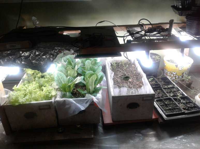 After making
my "LED light table" in early January, before the end of the month I
had planted leaf lettuce. In mid February I planted another box, this
time with romaine. By early March I was eating lettuce from the first
box. But not before putting the boxes on wheels for access and adding a
fan to prevent mold from growing on top of the dirt. In mid March I
planted a third box with spinach and another variety of romaine. In the
last day or two I started including a leaf of romaine in sandwiches. In
addition I started some seedlings in seedling pots and some tomatos in
a big pot.
After making
my "LED light table" in early January, before the end of the month I
had planted leaf lettuce. In mid February I planted another box, this
time with romaine. By early March I was eating lettuce from the first
box. But not before putting the boxes on wheels for access and adding a
fan to prevent mold from growing on top of the dirt. In mid March I
planted a third box with spinach and another variety of romaine. In the
last day or two I started including a leaf of romaine in sandwiches. In
addition I started some seedlings in seedling pots and some tomatos in
a big pot.
I started to get the idea that this could be a fabulous
product - not just the lights but a complete, ready made "LED Indoor
Garden - just add dirt, seeds and water for year round greens." One
could optimize it as lessons were learned, and people could start
growing without each one having to figure everything out for
themselves, find all the parts and do their own wiring. I added it into
the "dream budget". On the 24th I took a head of lettuce down to the
farmer's market just to show. People seemed suitably impressed. It
started to dawn on me that literally millions of people might want
them. One lady thought schools would buy them as a classroom
educational tool. Exciting idea! And another whole market!
 Somewhere in
there I fixed a couple of LED lights I had made some time back, and on
April 1st I took apart a BLDC motor and had a good look at it - my
quite new washing machine had broken and had to be completely
disassembled.
Somewhere in
there I fixed a couple of LED lights I had made some time back, and on
April 1st I took apart a BLDC motor and had a good look at it - my
quite new washing machine had broken and had to be completely
disassembled.
The subject came up
late last year to consider what a person involved with plans or
projects for advancing civilization in some way would
do if some
philanthropist multi-billionaire decided that some of his fortune
should be invested in improving the future of the planet, and offered a
virtually unlimited budget to give effect to a program of
implementation. The terms
would be that the money must put to productive use for the program, the
recipient would take only a fair and reasonable salary and not
otherwise help themself personally the money offered or to any
profits that might accrue. Would we ask
for 10 million? 100 million? half a billion? or a whole billion?
If we asked for too little, it would limit our potential
contributions to humanity. If we took more than we could productively
use, everything would be subject to cancellation for being wasted. Are
these various ideas and projects not priceless, worthy of such an
investment? Furthermore, with some of the projects having the potential
for swiftly becoming revenue generating, the seed money supplied would
surely turn into a self sustaining enterprise and return manifold more
fruits than the initial amount.
Wow - to have the resources to be able to get talented
people together as
required to go at each project full bore, and to have several things
proceeding
simultaneously? The ability to develop my ideas multiplied many times
over? Wouldn't that really kick-start everything! All those
development and research projects that I probably couldn't perfect in
my lifetime could rapidly be completed and commercialized! Useful
new products and technologies for everyone's
benefit!
Capital to commercialize projects with, and even to get a
reasonable salary for what I do, has been beyond my expectations for
many years now. The idea of having an unlimited potential budget to go
about several things or
even everything in a big way I shoved out of my mind. The possibility
just seemed so far off the radar screen. Perhaps it still is, but one
can hope! The last time I
had a salary and a decent budget even to
order
whatever parts and materials I needed for a project was over 30 years
ago (1985-1989),
when the facilities manager of the Victoria BC school district, Keith
Hawkins, had me hired. There I designed, built, installed
and programmed computers to control heating, ventilation and other
functions in the schools, when commercially available products were
pretty primitive.
Should this sort of fabulous offer be made to me, where
would I even
begin to guess how much money to ask
for, and how
to best put it to use? I decided to focus in on technical and
sustainable energy projects and products rather than those ideas for
improving democracy
and societal concerns. (not that setting up a web site or two for some
of
those programs might not be equally valuable!) Then I would break it
down into
very, very rough budgets for each separate project.
I should point out that all these projects are described
in past issues of Turquoise
Energy News going back a decade and are not brand new ideas that
have recently popped out of my head without having been thought out in
some considerable depth for some time, and in most cases have had some
actual development to some degree. Many projects have continuing
development, physical or conceptual, moving forward from their origin
even to this issue. Some projects I have left out as they seem to me to
be less valuable or lower priority than those selected.
I would start with projects I think are most certain to
quickly
start generating revenue, returns on the
investment: the Bandsaw Alaskan Mill, the Indoor LED Garden and the 12
Volt DC plugs and sockets system. But there would be no pause before
initiating the various projects that need more development and
research. Having multiple projects
running at the same time would be a
major advantage. Everything could be housed in one facility, or a
very small number of facilities next to each other to better utilize
resources and minimize fixed costs. There would be one head office and
one accounting department for all of them to split these overhead costs
between all the projects. And if one project needed
more resources (monetary or human) than budgeted, it might borrow
persons or funds from another budget as long as everything balanced
out. Usually, when a single project start-up business needs more
resources than allowed
for - as so often happens - it may go broke without success, or
dissipate
its efforts and "sell the farm" looking for supplementary funding, with
progress set far behind. With multiple projects, when one
becomes commercially successful, its revenue stream can help the
others. If one is seen to be unviable or no longer very valuable in
light of
other developments, or is not progressing well enough, it can be
terminated and its
resources and probably valuable personnel shifted to other projects.
The enterprise as a whole can become self sustaining before the the
initial capital runs low, while R & D for the next products is
ongoing.
The budget amounts
are the vaguest of estimates. I decline to write up
phony "business plans" that pretend to know in detail how much
everything will cost, how long it will take, and how much revenue will
be generated and how soon. (Apparently many forward looking investors
find formal business plans rather passé now anyway and use other
criteria to formulate their decisions.) The total budget is 22 million
Canadian
dollars. If that figure seems small compared to 100 million or a
billion, it's still a lot of money and a lot of good work can certainly
be done with
it!
Here is the "Table of Contents" short list of the potential
projects that I'd like to fund:
Bandsaw Alaskan Mill ("Carmichael Mill"): Manufacturing Business: $5
million
Standardized 12 VDC Plugs, Sockets, Wall plates, Adapters: Production
and Marketing: $1 million
Textured Solar Panel Glass to Improve Overall Collection: Development
and Production: $1 million
New Chemistry Battery(s): Development: $1 million
Permanent Magnet Assisted Reluctance Motor and Unipolar Motor
Controller: Development: $2 million
Ground Effect Aircraft for Islands and Inaccessible Rugged Coastlines:
Prototype Development: $4 million
In-Stream "Turbine Pipe" Hydro Power Generators: Development and
Production: $2 million
Indoor LED Garden Kit: Development, production and sales: $4 million
Contingency & Optional Projects Reserve: $2 million
Total $22 million
Here are Short Descriptions of each Project or potential
Product
Carmichael Mill ("Bandsaw Alaskan Mill"): Manufacturing Business:
$5 million
There are a lot of "knowns" in the bandsaw alaskan mill
project with
the "unknowns" being relatively few. We know chainsaw alaskan mills
work well. We know that bandsaw mills on tracks work well. Combining
these into a "Bandsaw Alaskan Mill" is therefore a matter of getting
everything right to constitute a good, practical tool rather than
explorations
into unresearched or undeveloped territory. I've already proven
that the first
prototype cuts well and is pleasing to use. Business,
production design (safety is of course paramount with any saw. This one
should be intrinsically safer than a chainsaw mill) and
marketing aspects will then be the main focus.
In the 1990s more than one person estimated (independently
of each
other) that it would take 5 million dollars to start up my computer
operating system business. Here product
development will be much faster than in a new software business, but
then this will be a manufacturing
business requiring a lot more space as well as equipment and the cost
of the actual parts inventory for the mills. So it might work out
around even. Notwithstanding considerable inflation since then,
administrative costs are shared between all the programs. So I'll call
it 5
million.
I believe the market for such saws will be large enough
that the
initial investment will be recovered in, say three years from the time
the first batch of saws is out there and people are seeing them at
work. That may be a couple of years from starting up, so give
it five years. (Making and selling 7000 mills netting $700 above cost
each would just about do it.)
I think this mill will both open up new markets (people
who wouldn't
have bought a full-fledged sawmill just for a few logs or even one
special one) and replace purchases of the smallest "low end" bandsaw
mills on tracks,
by being more practical: portability and milling logs without moving
them
to a sawmill, a lower purchase cost, low maintenance time and cost,
and
taking up little storage space when not in use.
CAT Standard 12 VDC Plugs, Sockets, Wall plates, Adapters:
Production and Marketing: $1
million
I think there's a big market for something similar to the
ubiquitous NEMA standards for 120/240 volt AC plug, socket and wall
plate systems,
created similarly for DC
battery systems for off-grid and portable applications. It's an area
with
much need and with a gaping vacuum of standards and parts availability.
I've created a couple of "standard" 12 Volt DC sets based on "AT"
automotive fuse pin and socket
design, and I make them on a 3D
printer. Real production and marketing would spread their use and make
them
a real, adopted standard. 24, 36 and 48
volt standards can also easily be created and produced. No one else so
far has
taken the initiative to create such a thing and manufacture and market
the products. With capital, it could easily be done and should be
effective. For 12 volt use, adapter plugs can easily give it both-ways
backward
compatibility with "car cigarette lighter" plugs and sockets, so
migration to the new system should be simple and painless. Such 12 volt
wiring for buildings can also utilize common and proven electrical
boxes (which the faceplates fit on), wire and
wiring components and techniques.
Textured Solar Panel Glass to Improve Overall Collection:
Development and Production: $1
million
The nanocrystalline titanium dioxide borosilicate glaze I
created
some years ago could be developed into a pebbly textured front surface
solar panel glass that would increase light collection, especially from
scattered and low angle light. The pebbly (little lenses) texture and
the high refractive index of nanocrystalline titanium dioxide reduces
reflections and bends more light straighter through toward the
collector
elements. This would increase effective solar
collection over a day, including in cloudy conditions when collection
is low, making any solar panel more effective overall. Since it hasn't
been tried the percentage
improvement is hard to determine. It could be
anywhere from 10 to 30%. 10% could make it worthwhile; 20% or more much
more so.
New Chemistry Battery(s): Development: $1 million
With capital, a full time real chemist could take my ideas
and
designs much farther and faster than I have been able to do. In
exploring "mildly alkaline" novel electrolytes, I seem to have
uncovered not
one but several potentially valuable new "better than lithium" battery
chemistries
that can
be worked out. For example using trace additives I got manganese to
hold its -1.5 volt metallic charge (world first!) to make
nickel-manganese
2.5 volt cells.
That's even higher voltage than lead-acid and high enough for digital
circuits and to drive LEDs, so
one rechargeable "button" or "AA" cell
could replace two other cells for many small products, and larger cells
should have very high watt-hours for their weight.
Nickel-nickel
has the promise of very high current capacity as well as high
watt-hours per
weight for electric transport.
Nickel-air, if it can be made to work,
could bring a whole new level of light weight electric transport
batteries - a car might
run for days before recharging. Nickel has advantages over other metals
(eg zinc, iron) for a rechargeable air cell, but the electrolyte is
again a key since it won't work in a regular pH 14 alkaline cell.
Novel chemical developments or ideas to date include the
~-1.5v manganese negative electrode, potassium oxalate for a less
alkaline (less caustic) electrolyte (along with calcium hydroxide),
possible use of ethaline DES as an electrolyte base with a higher
breakdown voltage than water, thin film conductive layer (osmium in
acetal polyester) to protect positive electrode current conductors (now
testing; looks like it works), chelation of active metals to prevent
gradual deterioration with cycling (for everlasting cycle life).
Taking the
chemical techniques developed or attempted so far to practical cells
for
production and market may well cost substantially more than this
budget, but,
anticipating a
delay before they're developed and ready for production, it might be
financed with
profits from more immediately salable items. (Or production might be
contracted out... to China or ?.)
And late this very month, I got a nickel-nickel test cell
working (here), demonstrating the above theories
work. I'm sure this is the chemistry to concentrate on for electric
transport. It should be cheaper and better than the lithium types
presently in use, and should have higher energy density. Rather than
add to the budget, contingency money might go toward setting up for
production if it seems warranted.
Permanent Magnet Assisted Reluctance Motor and Unipolar Motor
Controller: Development: $2 million
Here are opportunities to revolutionize the motor industry
with exciting new but little explored developments. Different motor
types use different types of solid state motor controllers, and the
novel reluctance type should be developed along with a controller for
it, as a pair.
The permanent magnet assisted motor has coils with
permanent magnets in them as well as electromagnets. Perhaps amazingly,
there's no external field if the coil isn't energized, but if it is,
the permanent magnets add their field to the electromagnet field,
providing more magnetism with less current and power than with an
electromagnet by itself. The ultra-efficient operation this provides
can drive electric vehicles with less applied electrical power under
heavy load conditions, potentially yielding much greater driving range
even with present batteries. My "axial flux" reluctance motor designs
with large diameter thrust bearings allow for very small gaps between
rotor and stator, a critical parameter of effective reluctance motor
operation. They are also easily produced, with CNC waterjet cutting of
the main metal parts.
The unipolar motor controller for reluctance motors is a
simpler and more reliable design of mine, with half as many active
mosfets as other controllers - allowing both forward and reverse motor
operation with single ended transistor drivers. Cost is thus
intrinsically lower and it should have fewer "failures per zillion
hours" of use. And the reluctance motor can run safely and efficiently
at very high RPMs, eliminating the otherwise valuable use for variable
transmissions in electric vehicles.
(If development goes smoothly, there
might be some capital left over to put toward production.)
Ground Effect Aircraft for Islands and Inaccessible Rugged
Coastlines: Prototype Development:
$4 million
This is among the potential things to make more of the
world more habitable, by making some isolated areas less isolated. The
ground
effect (or "surface effect") provides much more lift with much less
drag and so the craft flies low over water using perhaps 1/3 of the
fuel
or energy of a regular aircraft. It goes where a boat or ship goes and
isn't used over land. The main problem with commercializing
ground effect craft has been stability. It's extra critical when flying
just over the surface. Some promising testing of "catamaran" types has
recently been done by radio control model aircraft builders (see
youtube). But features of my "catamaran" designs (which would again
first be tested with radio controlled scale models for safety and at
low cost) would improve both lateral and longitudinal stability over
other types, with a high degree of confidence a practical craft will
result.
The design traps air under itself like a hovercraft. The
rear of the
central wing and the catamaran side bodies meet at the waterline to
form 3 sides of
a box, and a retractable flap at the front of the wing extending down
the same distance makes the 4th side. Some of the air from the ducted
fan propeller is directed into this box. This allows much lower power
take-offs, the craft lifting up at low speed like a hovercraft. It
starts to fly
like a ground effect airplane as it picks up speed (already
"airborne"), with the front flap
folding up under the wing.
Developing a practical, safe manned prototype of this sort
of
larger, more complex product will obviously cost more than for the
small items.
If this budget takes it only that far and successfully proves the
designs involved are practical, it will inspire and should be
considered a
success. If we can then
produce a multi-passenger model for more extensive trials and perhaps
to ply a formerly long and tedious commercial ferry route or two, or
even a long route where no ferry runs now, that would be marvelous!
Seeing
them in use might bring in orders for more and larger craft for various
such routes. (BC North Coast, between Hawaiian Islands, Norway Coast,
Azores Islands, Canary Islands, East Asian coast, Thailand,
Philippines...)
In-Stream "Turbine Pipe" Hydro Power Generators: Development and
Production: $2
million
There are designs,
computer modelings and a few successful individual
projects for making electricity with floating "catamaran" style
generators with paddle wheels anchored in rivers. The idea has
tremendous potential but no easily replicable or
production designs have ever come out. (Wind power was commercialized
in
Denmark and they soon became the major manufacturer. Flowing water
provides
continuous power - why should it not be done?)
This design would do even better. In the "turbine pipe"
(written up in this very issue of Turquoise Energy News), the main body
of the generator is a length of pipe with a center shaft holding a
number of propellers along its length - a "spiral staircase" of
propellers. An experiment (youtube) using such a system for a wind
plant has shown that this should give "the most bang for the buck" -
the most energy from a column of flowing water. The enclosed pipe
design along with a screened "funnel" intake also addresses various
concerns such as low water operation, ice, debris in the water, fish
safety, longevity and durability.
Small, easily deployed units could be manufactured and
sold. The smallest could be deployed even in relatively small streams.
Large units could potentially take the place of hydroelectric dams,
making as much electricity or perhaps more from the same water energy,
but deployed as floating units spread up and down the river instead of
everything being housed at a single costly dam site (with its potential
for eventual catastrophic failure).
The smallest units, perhaps a few inches in diameter and 3
or 4 feet long, for use typically in rapids in very shallow
streams, would simply rest on the stream
bed, held in place with weights or rocks, with the screened "funnel"
inlet potentially somewhat upstream and feeding through a hose to give
more pressure and flow to the turbine pipe. Larger installations, feet
in diameter and proportionately longer, would be anchored in a fast
flowing section of a river or a tidal flow, and would include
sufficient flotation for buoyancy and stability.
This project would concentrate on the small end of the
scale (starting with retail units of 12 volts, under a kilowatt?).
Assuming marketing these products brought more interest, later
designs would scale up to "industrial" size models for small community
and larger "on grid" power projects.
Indoor LED Garden Kit: Development, production and sales: $4
million
In temperate climates vegetables can only be grown "in
season" for part of each year. A greenhouse can extend this season but
much of the winter is still "out", with increasing winter cold and
reduction of daylight hours with latitude. This idea in its essence is
a pretty obvious application of LED lighting technology, which has
lately become "mainstream". Before LED lighting existed - and then
became "cheap" in big box stores - it wasn't realistic to grow
vegetables beyond the seedling stage indoors with artificial light. It
took hundreds of watts of lights making excessive heat to light a small
area. This LED vegetable growing idea has been successfully tested just
this year - indeed it has just been written up in the last issue of
Turquoise Energy News (#117) and this one, with lettuce started in late
January growing well and being eaten by early March.
In the process some less obvious things were discovered.
For example, a small fan (or fans) is required to circulate air to
prevent growth of fungus/mold on the surface of the soil. Flat rolling
dollies were made so the planter boxes could be pulled out from under
the rather low light table for access - watering, weeding and
harvesting. It would be easier to use if the lights were on a timer,
and perhaps an irrigation system could be provided to automatically
water - or a water bucket on top could feed a small hose to simplify
hand watering. This month it was realized that access would be easier
and less floor space would be needed if the entire light table pivoted
up and back like a freezer lid, with a latch to hold it open. For wider
units, that lighting lid might advantageously be angled left to right
or stepped (2 lids) to provide closer light on one side and more height
for taller plants on the other. And it or they might be adjustable
height lid(s). The unit could be raised up off the floor with storage
cupboards or drawers underneath for gardening supplies and tools.
The new part of the idea is to provide a whole "Indoor
Garden" product that is a complete solution, with all the features that
are found to be useful and practical well thought out and arranged.
That way anyone could start year round growing quickly and easily
instead of each person having to design and build their own from
scratch. There could be multiple sized models from "kitchen stove" size
to "large freezer" size for different needs and spaces, or perhaps
modular "kitchen stove" size units could fit together. They might pack
down into boxes for shipping and be assembled at home, as is so common
for furniture these days.
Contingency & Optional Projects Reserve: $2 million
However conservative the estimate, product development
usually takes longer and costs more than planned. Then, there
may be developments that go better than planned and may go into
profitable production earlier than hoped. For example a battery
experiment success or two (such as those this very month!) might mean
moving the project from "research" to "setting up for commercial
production" in weeks instead of months or a year or more. But some are
bound to lag behind. For example it might take much longer than
anticipated to solve some problem with the new motor or motor
controller,
and that would hold them both up. The reserve allows taking advantage
of the breakthrough on the one hand, financing lagging projects
longer, or both.
No doubt I could add to the "valuable projects" list, but
these seem
to me to be the most valuable items that I also have confidence in
because I pretty
much understand what needs to be done. I expect to hire self-motivated
talent that can be expected to proceed day to day with minimal
supervision and guidance. Still there's only so much one
person can initiate, direct and
oversee. I wouldn't want to spoil it by extending myself too
far -
not that I would want to absolutely preclude taking on a new idea or
project of great promise should one present itself!
And here already is such an example: the "LED Indoor
Garden" idea has made its appearance, with a prototype originally
intended just for personal use working since January and proving
lettuce (at the very least) can indeed be grown successfully in winter
with just 100 watts of LED light. Improved and commercialized it could
be a fabulous product used by millions, so it was added to the list.
Misc. Notes:
Apparently marketing via social media is now more
effective than
other techniques for introducing new things and someone good at that
would be
a valuable employee. As has been observed before, the trick to business
success is to hire people that are smarter, more talented and more
knowledgeable than you are. Or one might say, with different skill sets
in different areas.
In setting up an organization full of talented people (to
whit an innovative company with various departments), there may be
various opportunities to try out
"design team" approaches and new democratic systems in line with the
core values of social sustainability (Life, Quality of Life, Growth,
Equality, Empathy, Compassion and Love). With everyone understanding
that the financial "bottom line" is vital, it's possible the socially
sustainable approach could improve organizational adaptability and
contribute to long term success and an organization that continues to
learn and adapt and remain relevant through the centuries.
I think probably every department or project engaged in
development and research should contribute a monthly report. Turquoise
Energy
News would thus become considerably expanded. Since the
objective of the funding would be to improve the world, such reports
would make an excellent contribution toward further research by others
irrespective of the business success of each project. Even "failed"
projects would contribute to the human knowledge base, potentially
pointing better ways to future success by others, and so the money
would not
have been wasted.
Until "the ultimate best" technologies may someday be
created in all fields,
progress makes for obsolescence of existing technologies as new ones
are
created. For example antigravity craft will probably some day
make all
other types of aircraft including ground effect craft obsolete. (Things
do progress: When I was young, cell phones and the internet were beyond
science fiction!) As a "learning organization" this one should be in on
it as developments occur, phasing out production of ground effect craft
and working on potential commercial development of the new technology.
However, neither would it sit and wait for a
speculative unproven or virtually unknown technology instead of
developing technology (the ground effect craft) that
could be highly valuable in the present day and current conditions
probably for decades to come.
In Passing
(Miscellaneous topics, editorial comments & opinionated rants)
The need for teaching the core values of social sustainability
It is disheartening that the government in South Africa is
apparently now following that of Zimbabwe where all the white farmers
have been tortured, murdered or driven out. (I in fact know a couple from Zimbabwe who were lucky to
get out with the shirts on their backs - they weren't permitted to take
any possessions with them.) All the core values of social
sustainability are being violated: love, empathy, compassion, equality,
growth, quality of life and even life itself are being extinguished.
It's not like black people take over the farms. They are
abandoned. Zimbabwe went from being a food exporter to needing food aid
in just a couple of years. And it's not like blacks are reclaiming land
that historically belonged to them in all cases: there were no blacks
in the Cape of Good Hope area when Dutch settlers arrived there to
start farming. Until about 1960 blacks were under 70% of the population
and whites around 20%. From 1985 four million Africans entered South
Africa while 640,000 whites left - 15% (and probably the cream) of the
white population. By 2015 blacks were 80% and whites 8%. Where are
those who just a few years ago were "tsk-tsk"ing apartheid and asking
how white people could be so cruel and why blacks weren't allowed to
vote? Surely, that was nothing like an ideal situation, but what about
now? It's as bad as the Jewish Holocaust in Nazi Germany, in a
supposedly Christian country. With a growing black population, and no
consideration for the core values by the larger group, it was
inevitable that the governing power would shift and the concerns and
influence of the white and other populations would be marginalized. So
this collapse into barbarism has been predictable for a long time.
South Africa, where Dr. Christian Barnard once performed the world's
first heart transplant, appears to be sliding from being the one bright
light in sub-Saharan Africa into the same sort of primitiveness as the
rest of it. Will the blacks continue to tolerate the Indians and mixed
races, or are they next on the hit list? (And how long will Australia
maintain its current culture and identity when a tide of more southeast
Asian refugees than its whole present population comes pouring in?)
Perhaps this situation could have been avoided if everyone
had had to study, pass tests and understand the responsibilities of
democracy before being permitted to vote. That could have been applied
equally to all the races in South Africa. Hostile, ignorant
demographics might have settled down to study and understand broader
viewpoints and principles in order gain the right to vote. And of
course there would be more advanced courses for those who actually
wished to run for office. That would have been my plan for ending
apartheid. Alas, nothing like this was tried, nor has it been tried
elsewhere.
Closer to home there are also daily outrages to law,
order, morality and reason, complete with lies drummed over the
"corporate media" so repetitively "it must be true" to justify them and
obfuscate the issues. One can pick an issue and try and fight it, but
by the time any slow progress might be made, other similar outrages and
many dissimilar ones have been committed. (Someone spent 12 years in US
court having the so-called "patriot act" struck down. Obama re-enacted
it in a moment with the stroke of a pen.) Finally good people simply
throw up their hands in despair - it's hopeless. And our legal system
is so gutless that many of the worst social predators are never dealt
with. They remain on the planet for their whole lifetime free, even
rising to high places to instigate bigger outrages that harm more
lives, sometimes of millions of innocent people, and society as a
whole. How can and why should one try to fight a brush fire while new
ones are lighting up on all sides until the whole forest of society is
burning - and no one stops those lighting the matches and setting the
fires?
And where do the matches come from? Like every
civilization so far, ours has come about without conscious planning. It
had and still has no overriding goals for where it wants to go and to
be in the future and there's no planning for social, scientific and
technological change. Mostly it just happens, haphazardly. A
constitution or framework of operation is set up that is appropriate
for the conditions of the day, with only vague allowance for
"amendments", which are to be pushed through only with the greatest
circumspection by overwhelming majority, virtually in the face of
potential revolution. But those who framed the American constitution
could hardly have dimly imagined today's world.
British parliament passed the reform act giving most men
the right to vote by just one vote out of hundreds cast in the face of
the working American example, the most cogent arguments and with the
spectre of a potential "French Revolution" in Britain staring everyone
in the face, in (?)1830. Even back then it was noted pointedly that
"constitutions are fixed while society changes", yet no thought was or
is even now given to the need for provision for government and its
institutions to ever learn and reform to keep abreast of developments
and needs.
As the forest burns itself out and nations fall apart and
perhaps little will be left of many beyond the local community level in
coming decades, a fresh start has become necessary. In order to build a
civilization that lasts into the indefinite future, the root causes of
forest fires must be understood and preventative measures taken in
timely fashion. The way to start, humble and almost trivial as it
seems, is at the personal and the family level, where children learn to
think in sound, moral and right terms - or in terms of avarice, greed,
power seeking and other aberrant ways of thinking and living. Children
have to be taught to think for themselves, and given the highest set of
values that will enrich their own intellectual and spiritual
development as well as the community and society around them.
No Earthly civilization so far has thought about needing
to have ongoing means for growth, to have its institutions change and
adapt as conditions change. The ruthless figure out how to "game" the
relatively static system to their own selfish advantage, the
civilization becomes corrupted and the contributing public on whom
everything depends become increasingly overburdened, neglected and
impoverished, until there is a general collapse, usually with great
loss of life. (Even in the relatively recent and relatively mild
collapse of the Soviet Union people did go hungry and even starved, for
some years.)
Again, the 7 core values for social sustainability are
Quality of Life, Provision for Growth, Equality, Empathy, Compassion,
Love and summing up, Life itself. Are these not the highest social
values? And values always underlie all decisions.
There are many worthy secondary values. They are
implicitly based on the core values but they tend to supplant them,
giving rise to many aberrant paths of development. Renewable energy is
good - but why? Because it improves the environment. And why is that
good? Because it enhances the quality of life. So what's wrong with
renewable energy as a core value? If a society puts renewable energy
first, it may for example decide to develop and employ renewable energy
even at the expense of quality of life. If noisy windplants are set up
around where people live, it deteriorates their quality of life and
sacrifices even their environment. Inequality and discontent are sown.
Renewable energy must fit into place in a broad spectrum of things that
together determine quality of life. If quality of life and equality
were the first concerns, a solution that would be more satisfactory to
all would be sought.
Or, tolerance of people who are different and who do
things differently or do different things than we would is a good
value. There are many beliefs, tastes and and ways of living. But
tolerance is again a secondary value: once society tolerates predatory
behavior as it does today, where one person is able to violate the
rights of others with any degree of impunity, disaster and collapse are
waiting. Quality of life and equality are higher values than tolerance.
Only by explicitly including these core values in teaching
youth, so that these future leaders may in turn explicitly incorporate
them into their plans for social, political or economic uplift, will we
see plans formulated in ways that benefit everyone, leave no one out
and permit no one to lord it over others - in socially sustainable
ways. Many of us will at some time or another encounter situations
where these values can be used for effecting improvement at a personal,
family or community level, or in the workplace. But in the broad
picture such values will take a couple of generations to instill in
youth who then grow up to become better decision makers themselves.
Then they can start becoming broadly effective in transforming the
whole world, eliminating the root causes of forest fires to bring us to
days of "Peace on Earth and goodwill among men", the beginnings of
"days of light and life". In a century great strides can be made. In
two we will no more recognize society than the American founding
fathers would know ours.
In order that a program that will take generations to
mature not be lost and forgotten before it has a chance to come to
fruition, and will be sustained into the indefinite future, a new
institution is needed: one that gathers together the world's collected
wisdom on raising children to become fully functional, contented,
contributing adults without developmental handicaps, and teaches
parents, prospective parents, grandparents and teachers how to raise
their children in accord with this wisdom, so that it may taught and
instilled in each new generation. The internet will make it much
simpler to have such a program initiated and adopted around the world
than it would have been in any previous time. One might almost say it
makes it possible.
It may seem to many that such things are impossible of
accomplishment - that such developments are just not in human nature.
But this discounts what is sure to be severe "fallout" from the
environmental, economic and epidemic catastrophes that are looming in
front of us on our present course. When the things that used to work
aren't working and one's very life is on the line, people become more
open to change. And even today there is a rise in consciousness
occurring with a decrease in national, racial and ideological "us
versus them" attitudes and materialism, indeed not in the war hawks who
seem to want to rip apart everything mankind has accomplished to
justify their existence and enhance their personal prestige, but in
general and especially in the young. It will become increasingly
manifest in the coming years and decades, changes occurring perhaps
even suddenly when tipping points or triggering events are reached. We
may soon see students on the streets and on campuses marching to
protest inequality, and this will help redefine public perceptions of
what is true wealth versus material wealth and especially material
wealth gained at the expense of everyone else.
Feeble attempts at humor
How many times in a row can a word be used properly in a sentence?
Consider the sign:
FISHANDCHIPS
One might well say that the spaces between fish and and and and and
chips are too small.
(Or properly punctuated: The spaces between "fish" and "and", and "and"
and "chips", are too small.
---
Or how about just words that sound alike?
"The train stops here for 4 minutes from 2 to 2 to 2 2." (for not too
long - 1:58 - 2:02)
---
Which word is out of place?
Ring, rang, rong, rung
Rong: it's the only word that's spelled rong.
---
Baking bread is similar to digital electronics except that
rise times are measured in hours instead of nanoseconds. (Fall times
are still measured in nanoseconds.)
"in depth reports" for
each project are below. I hope they may be useful to anyone who wants
to get
into a similar project, to glean ideas for how something
might be done, as well as things that might have been tried or thought
of... and often, of how not to do something - why it didn't
work or proved impractical. Sometimes they set out inventive thoughts
almost as they occur - and are the actual organization and elaboration
in
writing of
those thoughts. They are thus partly a diary and are not
extensively proof-read for literary perfection and consistency before
publication. I hope they add to the body of wisdom for other
researchers and developers to help them find more productive paths and
avoid potential pitfalls.
Chevy Sprint
Car - Forklift Motor & Fixed (8.9:1) Reduction
Battery Placement
My plan was to make up the 36 volts in three 12 volt
sections in series. Each section would be charged separately, so it
wouldn't matter if all the cells weren't identical or even identical
types. (Four 3.2 volt lithium cells in series makes 12.8 volts. We're
still calling them "12 volts" and 12 cells in series makes "36 volts",
even tho it's actually 38.4.)
I had enough 100 AH
lithium cells to do an all lithium battery up to 300 amp hours at 36
volts: 36 cells. I had 45. (32 were from the Suzuki Swift. At least two
or three cells (not from the Swift) had the strange problem of not
freely going up in voltage from about 3.3 to 3.6 or more once they were
charged, which would doubtless cause charging problems even if they
worked okay otherwise. One cell had had that problem but when I tried
charging it a year later it was fine. Anyway there are a few spares.)
38.4v*300AH=11.52 KWH of storage capacity - not much more than the
Swift's 10.24 KWH and nothing like the Nissan Leaf's 26.4 KWH. A 400 AH
battery (15.36 KWH) would take 48 cells - a little out of reach. I
could also make it 340 AH by adding in twelve 40 AH cells I have.
(13.06 KWH) But I'd rather not mix them.
I could do 400 AH by using 32 of the lithiums for 24
volts, 400 AH, plus 400 NiMH "D" cells to make 12 volts, 400 AH. The
NiMH batteries are pretty much all put together anyway, so it wouldn't
be too hard to do.
 But then
there's where to actually put all those
batteries in a car not designed for holding them. I looked it over on
the 6th and finally decided to
keep it simple and put them all in the cargo space behind the back
seat. In order to fit them I decided to go with just the 300 AH of
lithiums. And that would weigh about 280 pounds - also more than enough
weight for back there. I would put a solid cover over and around them
and there
would still be some cargo space above.
But then
there's where to actually put all those
batteries in a car not designed for holding them. I looked it over on
the 6th and finally decided to
keep it simple and put them all in the cargo space behind the back
seat. In order to fit them I decided to go with just the 300 AH of
lithiums. And that would weigh about 280 pounds - also more than enough
weight for back there. I would put a solid cover over and around them
and there
would still be some cargo space above.
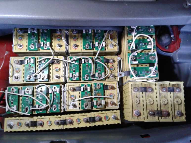
It took some puzzling to try and fit them in. It was as if
the batteries and the car were each designed to waste as much space as
possible to allow the smallest number of cells to fit. Each 12 volt
block of four cells was 5-5/8" x 11". So two were 11-1/4" x 11" and
turning
them sideways didn't really help. Four wide (22") wouldn't fit near the
bottom
of the spare tire space because of its gradual bends from vertical to
horizontal. But 3" higher up (read 3" less cargo space!) they would
fit.
Then for a second row behind the first there was... 10" - not quite
enough! All very frustrating.
Then I realized there was one trick left. The cells could
be electrically connected as blocks of four without being physically
stacked
together. If I put in just three cells per row, 10" was enough. So 7
sets of four would fit instead of 8. The remaining two would just fit
to the right, higher up, using up the cargo space on that side. (and
somewhat balancing out the driver left-right for weight?)
And there was one fortuitous thing about the 4-door
Sprint's layout: the tailgate didn't open to the floor. (I guess that
makes it a "hatchback" instead of a real "station wagon".) The
batteries, even the upper two at the right, would all be below the
level of the door. There was still room for groceries, etc, above the
batteries, as well as in the small remaining "full depth" space to the
left of them, and folding down the back seat still would make room to
slide in quite large items.
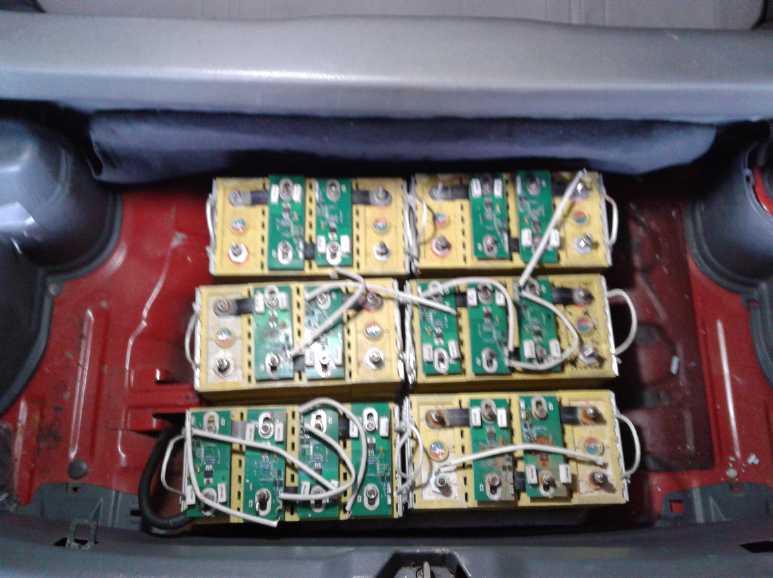
Continuing this subject, I spent some time on the 9th on
it. I cut some 2" extruded styrene foam, making rather
elaborate undercuts around the edges so it fit the spare tire well
well, and turned the batteries sideways to the way I'd had them. (Here,
saving 2 * 1/4" = 1/2" of length actually did help, allowing me to set
them an inch lower than the other way.) I could get in the seven 12
volt batteries, with just the rear one stretched out lengthways instead
of compact, and with little ventilation spaces between rows for
cooling. For the "balcony" at the right side (for the last two
batteries) I used 3/4" foam. (Say, shouldn't the cells be on spacers up
off the foam, so the bottoms get air for cooling? Maybe on a metal
grill or grid?)
The rear battery at the side was the thinner, wider shaped
cells of the same height (about the only place they fit well), leaving
just the 'malfunctioning' two cells of the original shape and seven of
the thin-wide ones as spares. (If I ever need any of the spares, I'm
not just sure how or if they'll fit.) But I spent a good portion of
this time cleaning dust and grime around the edges of the space with a
cloth and soapy water. (I thought I had already vacuumed and cleaned
the car?!? Ah... it was where I took out the plastic trim pieces in
fitting the cells. old car... road dust!) Let's see... a metal box for
the batteries? It had probably saved them in the Swift fire. If I left
the plastic trim off, the bottom, back, and right side, and the lower
part of the front, were already metal. I could bend up an aluminum left
side and a couple of pieces for the front, just behind the back seat.
3/4" plywood covers might be as good as anything, and would make a
solid cargo floor. Metal on the top is just an invitation to short out
battery connections. How about 5/8" firestop gyproc glued to the bottom
of the plywood? That would seem to have all the right properties.
With 250 pounds of batteries the rear springs were
definitely lower. But not bottomed out.
On the 11th I took a set of 4 cells apart and turned them
to make the thin, "stretched" battery. Now all were in place. But it
reminded me that where the radiator was was a thin space that I had
sometimes thought might be a good place for some batteries. I took it
up front and set it there. I measured the width for three such rows and
it was iffy - the innermost one was virtually touching the
transmission. But there was just a post in the way of putting them
farther forward. I disconnected the center link and nothing would
prevent putting the two halves of the battery farther forward, ahead of
the radiator grille area, except the horn. The horn could easily be
moved, or even its bracket simply bent to get it out of the way. I
could use the two sets of thinner, wider cells as well and save another
1/2 and inch, and have 4 of the "Swift" cells as spares for 28 in use
(excluding the two that charge funny), and 3 of the thin ones for 8 in
use.
That changed everything. The first 12 volts, 300 amp-hours
battery could be on a shelf at the front of the hood. The 24 and 36
volt batteries would be at the back, in the spare tire well. That
definitely improved the weight distribution: 185 pounds at the back and
95 at the front.
In the event I managed to make the front shelf so wide I
could fit any desired batteries onto it - even the extra set of 40 AH
ones for additional 12 volt loads - headlights etc.
 Then I remembered that I had to
put in the three chargers,
one for each 12 volt section. They added bulk and weighed 10 pounds
each. So much for the neat little box in the spare tire compartment -
the chargers needed the side shelves even without the extra cells. And
so
much for putting an extra 40 amp-hours of smaller lithiums on the
original battery shelf: the third charger had to go there. (The first
12 volts will have to supply the lights and other car circuits as well
as drive power. Owing to the low voltage I see no need for a floating
ground for the motor system, so 12 volts is 12 volts.)
Then I remembered that I had to
put in the three chargers,
one for each 12 volt section. They added bulk and weighed 10 pounds
each. So much for the neat little box in the spare tire compartment -
the chargers needed the side shelves even without the extra cells. And
so
much for putting an extra 40 amp-hours of smaller lithiums on the
original battery shelf: the third charger had to go there. (The first
12 volts will have to supply the lights and other car circuits as well
as drive power. Owing to the low voltage I see no need for a floating
ground for the motor system, so 12 volts is 12 volts.)
Hmm... and the chargers I had, heavy tho they seemed, were
only 10 amps. With 300 amp-hour batteries it could take a whole day to
charge the car! (At least if I put up some solar panels on the house it
could charge without overloading them when it was sunny.)
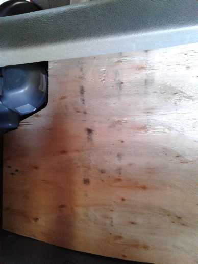 Carefully fitted plywood cover over the rear
batteries
Carefully fitted plywood cover over the rear
batteries
and chargers forms the new floor of the cargo space
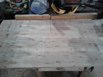 AWG! I accidentally sliced into it. It looked
about the same as the
AWG! I accidentally sliced into it. It looked
about the same as the
regular plywood saw table where I had set it to glue a minor flaw,
and I set a board on top and cut it to length!
More...
The Lovejoy couplers arrived on the 5th. I took the motor
and plate off the transmission. Replacing the one on the
transmission was simple. The other was more challenging. The inner
spline was rough and didn't readily go onto the motor shaft. Filing it
a bit didn't seem to help. It seemed that I could pound it on, and the
hammering beat the rough projections out of the way. (Maybe a very
small wire brush?) But the bigger problem
was that the L110 size didn't quite fit through the hole in the
mounting plate. The choice was to grind or gouge the hole bigger, or to
turn the coupler down a little on the lathe. I decided on the latter.
At the same time I could turn the back down so it would fit on the
motor shaft without spacing washers - the back of the Lovejoy would
replace the washers to hold the bearing cone securely and at the same
time be a little better seated, the
spline on the Lovejoy being much longer than the motor shaft. A little
more of the splines would be coupled.
I did this turning on the 7th. I ran out of "Valcool"
special formula cooling water, which also evidently reduced friction,
to drip on the carbide cutting tool. I didn't know where to get more
locally and I didn't want to go to town in the middle of the job
anyway. Oil wasn't as good. Straight water would make rust on the cast
iron. I added soap and baking soda to some water. The soap might reduce
friction, and the alkalinity of the baking soda should inhibit rust.
(Perhaps there's a better formula I could look up on the web?)
(I couldn't seal the cup & cone bearing, and the
Lovejoy coupler was quite close fitted. Could grease be squeezed in, or
would the motor have to be dismounted and the coupler pried off to
grease it? Not the best arrangement for routine inspection and
maintenance!)
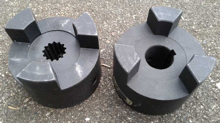 Connecting the splined-shaft motor to the
transmission shaft - the L110 Lovejoy Connectors
Connecting the splined-shaft motor to the
transmission shaft - the L110 Lovejoy Connectors
 One on the end of the shaft in the transmission
 With the mating one in place, one sees that the
motor will stick out from the transmission
With the mating one in place, one sees that the
motor will stick out from the transmission
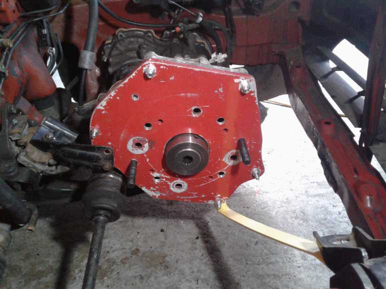
Steel strap (yellow) was added to support the right end of the motor
and transmission
Then I turned to
the missing right-side support for motor
and transmission in the car. With the motor off, I found another hole
at the very bottom of the motor plate. It seemed to have no purpose.
(Maybe for the manual transmission?) That was the lowest thing to run a
diagonal support from. I drilled a matching (3/8") hole in a bar of
steel and bent the end around to fit behind the plate and extend the
bar toward the original engine support. After deciding about how high
up to raise that end of the assembly I cut the bar to length and
drilled a hole at the other end. It'll pull to the side (and somewhat
forward) more than up, so it builds in quite a bit of stress, trying to
pull the plate off the transmission from the bottom, and at the other
end to pull the mount off the frame. But I decided 120 pounds of motor
and
transmission just isn't heavy enough to worry about. (Otherwise I could
try to balance it with a tube from the same engine mount to the top of
the plate, which would push instead of pulling. I still wouldn't call
that ideal, but I think it would be the best that one could do short of
welding in a new piece(s) of frame to hold a new cushioned mount
somewhere underneath - major work. I tried fitting the motor and was
relieved that the new bar passed by to one side (by about an inch) and
didn't hit it. (The 51 pound motor was too heavy for me. When I tried
to fit it into place by hand, I couldn't get it lined up and ended up
suddenly lowering it rapidly to the floor, almost dropping it. Next
time I wore
gloves, and put a big block of wood in place under it to hold it up
while I aligned it with the bolts. I'm sure 30 years ago I could have
done it by hand!)
On the 8th an L110 'spider' arrived in the mail, purchased
by a friend in Victoria at considerable cost. Good timing! I put it in
and pushed the second Lovejoy coupler into the hole in the plate. It
stuck out almost an inch. I was going to disassemble the tranny, take
out the shaft and cut an inch off it... then I thought it might be just
as good to have the motor sticking out farther instead of tight against
the plate. The mounting bolts were stiff, and long enough. It'd need
some spacers or something to hold it securely.
I securely mounted the plate on the tranny, then
remembered I hadn't tightened the set screws on the inside Lovejoy. I
took it off and tightened them, then I screwed in another couple on top
to hold these inner ones in place. I wrote on the Lovejoy "4 Set
Screws!" hoping the felt pen would last and that the note would help
anyone who couldn't figure out why it wouldn't come off with the
(outer) ones loosened.
I greased the bearing on the motor and tapped the splined
Lovejoy onto the shaft until it got to the bottom, to the bearing, and
stopped. The set screws on this one were almost an inch long, and 3/8"
diameter instead of 5/16". That was probably much better, and there
wasn't room left for outer ones. Then I attached the motor. It was
1.50" from the plate measured at both bolts. There was a small scraping
noise at intervals as I moved the car, as the motor turned. The motor
hung down a bit. I stuck a short piece of 2"x4" lumber (actually 1.5" x
3/5") under the lower side to even it up to 1.5" all around. Now it
scraped more of the time! It could hardly be anything but the Lovejoy
coupler rubbing on the plate. Evidently the "jaw" end, which I had
thought would be within the plate and left a bit wider, needed to be
reduced just a bit more to clear the hole.
With a battery connected, again the car moved "maybe" with
6 volts, slowly with 9 and faster with 12. (Perhaps it's ironic that my
Electric Hubcap motor probably would have done about the same if
connected to the tranny the same way - but its lower RPM would have
limited the travel speed even for city use, and it probably would
overheat in actual driving.)
Sometime I decided that the motor controller should go
inside the car, out of the weather and road dust. There wasn't much
room if one still wanted to be able to use the passenger seat, but the
shift lever was gone so was space in the middle from the parking brake
to the heater ducts. A controller just behind the firewall would still
have pretty short cables to the motor. Perhaps all the drive
electronics (circuit breaker, relay, heavy contactor, motor controller)
could go inside in a narrow "center column" enclosure, just leaving the
heavy cables to the batteries and motor out under the hood?
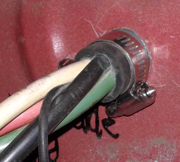 On the 20th I made a hole to pass the cable through to connect the
batteries at the back to the front. I had just one Greenlee hole punch,
1.18" diameter, purchased a couple of years ago at an electrical
wholesaler. The hole was just large enough to get the wire through with
little to spare. No room for a clamp or a gland. I came up with a
two-part solution: I rolled a piece of sheet steel and wrapped it
around the wire, and I put a pipe clamp around that. The steel stuck
out 3/4" from the pipe clamp. I worked the cable and the steel ring
into the hole and tightened the clamp. The steel would protect the
cable insulation in the hole and the clamp would both hold the steel in
place and prevent the cable end from being pulled into the hole.
On the 20th I made a hole to pass the cable through to connect the
batteries at the back to the front. I had just one Greenlee hole punch,
1.18" diameter, purchased a couple of years ago at an electrical
wholesaler. The hole was just large enough to get the wire through with
little to spare. No room for a clamp or a gland. I came up with a
two-part solution: I rolled a piece of sheet steel and wrapped it
around the wire, and I put a pipe clamp around that. The steel stuck
out 3/4" from the pipe clamp. I worked the cable and the steel ring
into the hole and tightened the clamp. The steel would protect the
cable insulation in the hole and the clamp would both hold the steel in
place and prevent the cable end from being pulled into the hole.
At the same time I checked
the size of the 100 watt solar panels versus the roof of the car. From
side to side, they only stuck out about 1/2" over each door frame, so
it's unlikely anyone would hit their head on one getting in or out.
There was easily room for two front to back, but a third one would have
to extend way over the hood. One wouldn't be watching the birds! Two
wouldn't quite provide a full charge if simply connected straight
across the batteries (with a diode to prevent discharge). The voltage
was a little too low. Maybe, gradually, a 3/4 charge. (OTOH it would
never overcharge - no precautions would be required. But this is where
one wishes some "non-standard" voltage panels were available to provide
just another volt or two - 23 or 24 instead of the ubiquitous "(~)21.6
open circuit volts" rating. OTOH "specialty" panels would surely cost
twice as much.) Well, maybe a DC to DC converter would be the best
answer. But that should come with a "full charge" detector and shutoff.
There the electronics start to become custom projects. The seemingly
simple idea of connecting solar panels to charge starts to get messy.
On the 21st the motor controller and programmer arrived.
(Also the now spare L110 Lovejoy rubber "spider".) The controller was
surprisingly small, smaller than the gearshift lever enclosure, and I
could see it would fit easily in the center column space. Then there
were the external components: 12V relay from car key, 36V main
contactor relay, circuit breaker, polarity protection diode and
controller fuse. These were almost the same as for the Kelly
controller. I had mounted them on an aluminum plate that attached under
the hood. Could they all go inside the car? I dismounted the plate and
put it inside. Part of the plate was in the way of the gas pedal. Then
I turned it sideways. If I cut off the part of the plate where the
Kelly controller had sat, and removed a terminal strip, it was close
enough to ideal. (I don't have to redo it from scratch? Really?!?) The
Curtis controller would sit 2/3 off the end of the plate, but sheet
aluminum could be bent up and around to form a top and back for the
enclosure as well as help carry off any heat from the controller. I
dismounted the components and cut the plate.
Probably only for my own reference here are the wires I ran from a two
foot long 12 wire cable to the controller's 16 pin molex connector:
Connector Pin - Wire color (resistor color code)
----------------------------------------------------
1 -
2 -
3 -
4 - 4
5 - 5
6 - 6
7 - 7
8 -
------
9 - 9
10 -
11 - 1
12 - 2
13 -
14 - 8
15 - Lite brown
16 - pink
The other end of most of the wires in the cable went to the terminal
strip under the dash, previously wired with speed control pedal,
forward-neutral-reverse switch, and (wired at last?) 12 volts from the
car key when ON. The cable was short enough to pull out individual
wires that went to the nearby components on the plate. The cable that
had previously run from the strip under the dash to the one under the
hood for the Kelly controller was removed. (Hmm, I guess there'll be no
RPM reading from the motor!)
I picked away at the wiring. I had #2 AWG heavy wire but
no lugs to crimp onto the ends. I finally bought some but at the same
time I decided it was awkwardly heavy anyway. I bought two 5 foot #4
AWG battery cables and another piece 6 feet long. I put all the lugs
together into (I thought) one ziplock bag. The cable for the batteries
in the back, a "cab tire" cable with four #6 AWG, was too long, and the
36 volts from the back only had to go to the motor controller in the
car, not up under the hood. The 12 volts on the other hand went from
the batteries at the very front to the back. I kept looking at it but
couldn't see anything for it but to strip the outer rubber off for
seven feet. I tackled that on the 29th and my thumb was sore for two
days from pealing back the outer rubber as I went along. I sat down
comfortably to do it. I used a sharp knife but put a short piece of
2"x10" cedar on my lap so I couldn't stab myself in the leg if the
knife slipped.
Finally on the 30th I went to get the lugs for the last
two wires... and couldn't find them. I looked for over an hour. I found
another bag with 3 stray lugs, a bit small, and finally decided 2 of
them would have to do. I tightened up all the connections and connected
just two batteries to try it out at 24 volts. (Would that really save
the controller if there was some fatal problem?)
It was only much later I remembered that the new lugs for
the #2 wire had come in a small unmarked box, and I had stuffed the
whole ziplock bag of all my heavy lugs into it. It was right there all
along, but of course I was looking for a bag.
With everything ready, I disconnected the motor power
wires at the controller then got out the Curtis programmer and plugged
it into the controller, then turned it on. Nothing blew up! I reduced
the maximum drive current setting from 300 amps to 120. (If I had had a
programmer for the Kelly BLDC controller in 2016, I'd have set it
somewhere below 200 amps and it probably wouldn't have blown when the
motor shorted.) The programmer showed the forward/reverse switch was
different than I had it and the switch's wires needed changing. After I
got it out from behind the dash, it was easily done with the contacts
being lugs and screw terminals. I noticed the motor controller LED was
blinking a pattern. (.. .
.. .) I found an "initial checkout procedure" in the manual that
I should have been following. It said to go to the "faults" page on the
programmer, but there didn't seem to be a selection with that name, or
I'd have already been there. I went back in the house and checked the
LED fault code meanings in the manual. It was something to do with the
'throttle'. It was preprogrammed for a differently wired type than I
had put in the Sprint. I changed it with the programmer to my type.
Another blink code... Next it turned out the "pot high" and "pot low"
were done in reverse, so "off" meant full throttle. I swapped the
wires. Finally the controller was happy and just did single blinks.
"Monitor" on the programmer showed how far I pressed the pedal, and
when I moved the forward-neutral-reverse switch, now with the desired
result. I reconnected the motor wires. But still the contactor never
closed to give power to the motor. I finally realized that I had to
pull the "interlock" pin high. I wasn't using an interlock switch and
had wired for use without it, and hadn't realized the pin had to be
pulled up to 36 volts just the same. By this point it was dark and
getting quite cold after a sunny, warm day, and I quit for supper.
I returned to the chase in the morning and hooked up the
wire. This time the contactor clicked on just after I turned the
breaker on. Surely everything was ready to go, barring any adjustments!
I jacked up a wheel so the motor could turn freely. But when I pressed
the pedal the contactor clicked off and it started telling me the motor
field coil was shorted ("field shorted or resistance too low or short
to ground or B+"). I started adjusting parameters related to the field,
and got it to at least start to turn, but I couldn't get it to run
nicely, and it kept shutting off. I disconnected the controller and put
1.00 amps through the field, and measured 12.9 mV, ie, 12.9 mOhms (DC).
And there were no shorts to the case.
When I had just hooked up a battery with the armature and
field in series, of course the field current was identical to the
armature current. 75 amps was 75 amps. The controller would only put
out 5 to 25 amps to the field. If the field current is only 1/4 as
much, doesn't the armature current have to be 4 times as much to give
the same torque? So 75 amps at the armature only made maybe 1/4 as much
torque? Wouldn't the armature need 300 amps for the same torque? Does
that follow?
Had I got the wrong type of controller? Should I have just
got a "series wound" controller and hooked the windings in series? But
the manual said the parameters could be programmed to handle "nearly
any" separately excited motor. Why should it not handle a typical
forklift motor?
Then again, I had set it to 120 amps max, thinking that
was a lot more than the 75 when hooked straight to a battery. But 120
amps armature current would be at a pretty low voltage, so it surely
didn't mean anything like 120 amps battery current. Maybe I should have
left it at 300 A? I set all the settings back to 300 and hooked up an
amp clamp meter to the B+ (24 volt) power. Sure enough, the battery
supply current was only around 10 to 20% of the armature current. It
didn't quit and the motor ran. It still didn't seem to have much
"oompf".
I lowered the car and tried driving forward. It just
started to move and shut off. Reverse was about the same. (The
directions were right.)
Further checking of the manual showed a "motor warm" field
resistance example of 900 milliohms (.9 ohms), and "motor hot" of up to
2.5 ohms. It couldn't be set lower than 100 mOhms. If those were DC
resistance measurements, by comparison 12 mOhms was a "short circuit".
In fact, wouldn't that be more the resistance of an armature coil? Four
equal size bolts for connections... could the motor maker be so devious
that the connections right by the brushes were the field, and the ones
off toward the middle were the armature? I took the other connections
off and measured: 49.6 mOhms! Surely that was it - I must have had the
field and armature connections reversed! So I swapped the wires. It was
worse. The field current jumped all over the place, including to levels
above its maximum, while the armature current hardly moved. And it now
shut off as soon as I pressed the pedal. Furthermore, putting a meter
lead directly on a brush showed it was connected to where I originally
thought and not to the other. But why would the armature have much
higher resistance than the field coils?
An answer came to mind, but not one I had any confidence
in: The motor depends on the magnetic interaction of the armature and
field coils. What was the difference which was which? Isn't the
armature always the high current and the stator field the low current
one? Perhaps this motor was reversed: the armature was the low current
"field" side and the stationary field was the high current "armature".
Sheldon had said of them "The brushes never wear out." That would make
more sense if they were carrying the lesser current instead of the
greater. And if it was possible, it made sense to make it that way,
too. There'd be less brush wear and lower resistive losses with the
high current not going through the brushes. That didn't seem to help
the motor controller any. It started to hail for the third time and the
washing machine had broken down with my laundry in it. I was ready to
quit.
Then I thought of a couple more things. By leaning against
the car until it moved I rotated the motor, while checking armature
resistance to see what effect the turning and brushes had. The 49.6 was
the lowest reading I got. More typically it said 80 to 150 mOhms,
fluctuating as the motor turned. Those were the sort of resistances the
manual mentioned for a field coil. I decided to turn off the "Field
Check" programming parameter, presumably preventing it from checking
for shorts or opens and shutting off owing to fluctuating currents. It
didn't work. The diagnostic was still "field shorted" after it shut off
whenever I tried to drive. Why should that be if sensing it was turned
off?
Then I found in the manual that a monitor value called
"mot res x10 mΩ" was actually motor field resistance. I turned
it back on and looked. With a few seconds between each reading it said
0... 2... 4... 6... 8... 10... 12... 14... 16... . What was that all
about? Could the controller be defective? Maybe if I waited longer it
wouldn't say "field shorted"? But "16", for 160 mΩ, should have been
high enough, and it shut off all the same. Turned off and on again, it
would restart its counting from zero.
More hail and then snow ended a rather disappointing day.
But nothing had blown up yet (except the washing machine and the
computer video monitor I'd been reading the manual on). I pored over
the manual again in the evening looking for clues, occasionally going
out to the car to check something. (I had a spare video monitor. Why
did I give away the spare washing machine? Now what's with my
flashlight? I've heard that eventually catastrophes will be pouring in
upon us, but this is getting a bit personal!)
What were those weird field resistance readings, why did
the field current fluctuate so much and why did it keep tripping off
whenever I tried to drive? Reducing the "minimum field current"
parameter reduced the humming I could hear when I turned it on, but
didn't stop it from tripping off when I touched the pedal. Finally the
day, and the month, expired. I sent an e-mail for help to Canev.com,
hoping this situation and its cure are known. (It wasn't.)
BLDC Motor
Disassembly
With the washing machine
having quit on the last day of March while I was working on the
Sprint/forklift motor/Curtis motor controller, it became top priority
for April 1st and I spent the day on it. To take it apart I had to take
the motor rotor off. Of course I wasn't going to let it go by without
having a good look at the motor. It was an interesting BLDC motor that
drove the clothes basket directly, just such as I'd heard had taken
over from the old induction motors with complex transmissions. The
motor was on the back, outside, with the basket on the same axle
inside. But the basket had come loose and was flopping around. The
entire machine had to come apart to get at the back of the basket.
(YOW!)
So I got my first and unintended look at a modern BLDC
washing machine motor. It had three connections for the three coil
phases. But it only had a four pin connector for the magnet sensors
instead of a 5. I'm not sure how that worked. The five pins are for
ground, power and three hall effect sensors, one per phase. I can come
up with ideas... like that at least one is "high" at all times, and
half the time two, so the power might be pulled from the one(s) that's
high to power the one(s) being driven low? Maybe something like that.
The motor controller was in the bottom of the washing machine.
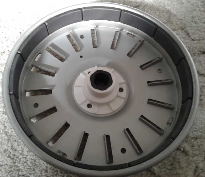 Rotor
Rotor
The inside of the spinning drum, the outer rotor, had 12
curved magnet pieces. I say "pieces" because checking with another
magnet revealed that each one had four poles instead of two, and was
thus two magnets in one:
------------- ------------- ---...
|N--S--N--S||N--S--N--S||N-...
------------- ------------- ---...
So there were actually 48 magnet poles instead of 24. This
matched the 36 narrow stator coils, in the very configuration I'd
proposed myself as "BLDC4:3", 3-phase (4 rotor magnets to 3 stator
coils) configuration, thinking it should have more torque than with the
usual 2 magnets. (I should have known for something so apparently
simple that someone else would have already done it!) But they seemed
to be just ferrite magnets, not supermagnets, so ultimate torque
couldn't have been the aim. Cooling fins were die stamped out of the
rotor side and bent to 90°, the voids forming air slots in the
side. The center had a splined hub, which fit onto the splined shaft
that turned the clothes basket/drum.
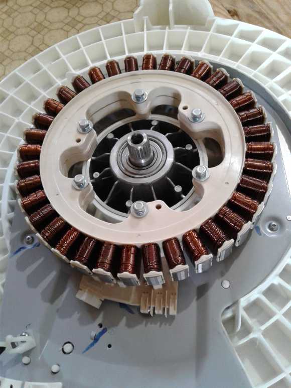 Stator
The stator was made up of the usual insulated motor
laminates, a big "O" with 36 "posts(?)" sticking out to make each coil
core. Each sheet occupied .5 mm thickness. This was almost entirely
covered by a two piece plastic cover, upper and lower. The coils were
wound onto the plastic spools around the posts. Depending on how many
layers there were, there may have been 60 or 80 winds on each coil. For
120 volt operation, the 12 coils of each phase were in series. (Or
maybe it would be closer to 150-160 volts if the 120 VAC was converted
to DC with a diode bridge and filter capacitors. For lower voltage
operation some could be put in parallel, eg, four parallel sets of
three coils for 40 volts instead of 160. ) There was no extra
insulation anywhere besides the thin magnet wire insulation, but some
tiered plastic posts molded into one cover kept the wires about .1"
apart between phases. As I found in the Electric Hubcap, keeping the
wires spaced apart is better than insulation. There was also no motor
varnish or epoxy anywhere, but all the wire was so tightly wound and
run that there was little place for vibrations to move any and fray the
insulation.
The flux gap diameter (or effective motor diameter) was
about 258 mm (10.15"). Unlike the axial flux motors I've been working
with with their 1/2 inch flux gaps, this flux gap was small, around .8
mm. Such tiny gaps are where it is said that the coils may eventually
demagnetize the rotor magnets.
I wonder what the torque and RPM specs for that motor
really look like? The clothes basket is certainly really moving on
"high spin".
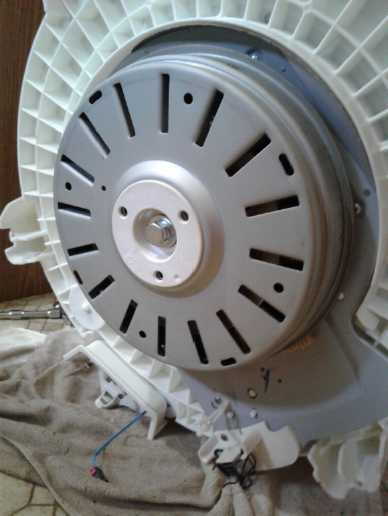
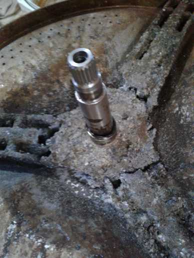 The problem with the clothes washer was rather sad: The three heavy
spokes of the entire main supporting hub for the basket had broken,
leaving it hanging. It left bits I thought at first were small rocks in
the bottom of the tub. It would take quite a lot of stress on the
"spin" cycle, still it should have been designed for it - and it looked
heavy enough. But it looked corroded, or at least filthy. Of course it
was immersed in the water tub. The pH of the tap water tested as about
6. Didn't sound too corrosive. It spent its first two years in
Victoria, and I don't suppose the water there was much different.
(Nothing like Port Hardy and the north end of Vancouver Island with its
so-called "natural acid rain" [down to pH 5 and below]. But that quit
happening after Utah Mines closed its copper mine there. Little did we
suspect!)
The problem with the clothes washer was rather sad: The three heavy
spokes of the entire main supporting hub for the basket had broken,
leaving it hanging. It left bits I thought at first were small rocks in
the bottom of the tub. It would take quite a lot of stress on the
"spin" cycle, still it should have been designed for it - and it looked
heavy enough. But it looked corroded, or at least filthy. Of course it
was immersed in the water tub. The pH of the tap water tested as about
6. Didn't sound too corrosive. It spent its first two years in
Victoria, and I don't suppose the water there was much different.
(Nothing like Port Hardy and the north end of Vancouver Island with its
so-called "natural acid rain" [down to pH 5 and below]. But that quit
happening after Utah Mines closed its copper mine there. Little did we
suspect!)
The washing machine was only around 3 years old and it had
worked great until now - better than almost any other and certainly
better than any previous one I had ever had. But 3 years isn't much
bang for the buck with the cost of a new washing machine!
I took my laundry into the shower and bath with me to
rinse them. With no "spin" they'll take a coon's age to drip and then
dry in the dryer! Working on the machine took the whole day. It was not
a part one could fix. To order the part one must buy an entire basket
assembly, for half the price I paid for the entire machine. (Is it
worth it?)
Other
"Green" Electric Equipment Projects
Carmichael
Mill ("Bandsaw Alaska Mill")
On the 7th I dropped in on
someone on my way by his place. He had told me he was making a water
wheel for his little creek, and after some days I thought of giving him
my little car alternator converted to permanent magnet alternator to
get electricity from it. (TE News #104 & #103)
He wasn't home, but a 6th sense told me to look around his
acreage for something I wanted. In a derelict pickup truck was an odd
piece, a clamp of some sort. I recognized that it was similar to what I
had envisioned for holding the band guides in the mill: thick extruded
aluminum
with a "hinge pin", and a bolt to tighten it. With a spring along the
bolt it could hold the band guide wheels and turning the bolt would
minutely adjust the angle of the guide wheels. Maybe if I took it to
someone
they could tell me what it was.
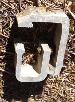 My friend
stopped by later. He hadn't been far off,
working, and had seen me come and go. He told me it was a canopy clamp,
to hold a canopy on a pickup truck. And there were probably more of
them there for the taking, so I could get the required two.
My friend
stopped by later. He hadn't been far off,
working, and had seen me come and go. He told me it was a canopy clamp,
to hold a canopy on a pickup truck. And there were probably more of
them there for the taking, so I could get the required two.
I gave him the alternator. The next day I went back and
left him the
poly-V belt and the other pulley that match it. I found three more
canopy clamps, but only one more of the same type. The other two were
useless. Anyway I got what I needed for the prototype.
The plan would be to cut off the clamping parts and keep
just the hinge with two flat sides. The short one with the pin sticking
out would be attached to
the saw post. The band guides would be attached to the longer piece
near the hinge. There their angle could be adjusted without moving them
in and out very much. They seemed to be about the right size. The (new)
'thumbscrew' adjustment bolt would
go through the post to keep the hand behind and as far as possible
from the cutting band while adjusting. (The adjusting should of course
be done with the saw stopped, but one can't guarantee that it always
will be, especially once they are being sold... or even before. I
suppose one could have two triggers and thereby force the operator to
have both hands in position to turn the saw on, but that would probably
be annoying. In a long cutting session it is nice - even vital - to
relieve stress by changing one's grip now and then.)
On the 11th I tackled one of them. I cut off the "extras"
and drilled and tapped holes for 1/4" bolts for the two guide bearings.
On the 14th I cut holes for mounting it on the saw. I got sidetracked
by various things. I had intended to finish it up and test it before
the month ended (or at least before this newsletter), but the battery
project and then trying to get the Chevy Sprint motor/car running kept
me from it.
Indoor
Vegetable
Growing With LED Lights (and other gardening)
Lettuce boxes, March 10th
(The 'volunteer' potato at the back now towers
over the lettuce and is up among the light bulbs)
 Not far into
March I
started picking out some of the lettuce plants started in late January
and eating them, to thin them as the big box was getting crowded. At
first they weren't much but a small addition to salad, but they
continued to grow well. The "counter lettuce" (romaine) in the other
big box went from little shoots to having some small substance by the
10th. In little bedding pots I planted more tomatos "moneymaker" and
"roma" (just as just one of the earlier ones finally came up in the big
pot),
and peppers, and by the 9th, cucumbers and zucchini. By the 13th a leaf
lettuce plant was the base for a single serving salad.
Not far into
March I
started picking out some of the lettuce plants started in late January
and eating them, to thin them as the big box was getting crowded. At
first they weren't much but a small addition to salad, but they
continued to grow well. The "counter lettuce" (romaine) in the other
big box went from little shoots to having some small substance by the
10th. In little bedding pots I planted more tomatos "moneymaker" and
"roma" (just as just one of the earlier ones finally came up in the big
pot),
and peppers, and by the 9th, cucumbers and zucchini. By the 13th a leaf
lettuce plant was the base for a single serving salad.
That seems pretty good. We had freezing weather with snow
and hail into the first week in March. So these are well over 2 months
ahead of greenhouse lettuce which might be planted in late March and 3
months
ahead of an outdoor garden planted in April. I'm probably almost the
only person around here having home grown lettuce in March, and I've
never before had any before May myself. On the 13th
I filled 2 more boxes with dirt and planted one with some spinach and
another variety of romaine. Next winter I'll be
able to grow all winter. (Now... what else to grow besides lettuce and
spinach?) How about a tomato? Onions?
Since the trays roll out about like drawers for access,
the operation takes twice as much floor space as it actually occupies.
On the 15th it occurred to me that if the light "table" had hinges or
other pivots at the back, and a catch to hold it vertical, it could be
stood up against the wall and be out of the way. Then one wouldn't need
to pull the plant trays out for access: just put the lights up, and
have access along the whole top. By pulling out single trays, access is
best - from all sides. But if there was any shortage of floor space,
and just in general, inspection and watering would be simplified by a
folding light table. (Well, maybe next year?)
Another point: water has gotten under the plastic I put
down to keep the floor clean and dry, a couple of times. I need a
better system to keep excess and slopped water contained, and it
probably shouldn't be plastic right on the floor to trap water
underneath. The wet will curl up the edges of the floor tiles.
At that point, one might actually have a product that
people would buy. The LED light table: "Grow vegetables year round in
your house." ...In fact, one could offer the "complete solution":
lid with lights, control timer and silent fans, adjustable height to
accommodate different plants and pots and hinged at the rear to pop
open for easy access from above. Underneath it could have roll-out
trays and exact size planter boxes to fit the rollers and make maximum
use of the space. Maybe a big plastic mat to catch spills. "Just add
dirt, seeds and water!" (But wait... there's more!) Hey, maybe an
irrigation system on a timer? And let us not forget different sized
models for different needs. Maybe some with two tiers? I could see
people lining up,
pre-ordering, to get one! And eating better vegetables and perhaps
faring just a little better in lean times for having and using it.
(Maybe I should add it to the "fantasy budget"? ... Done! Wow, one
might sell millions of them!)
The LED Garden April 1st.
4 or 5 heads of leaf lettuce have been plucked and eaten. The romaine
has grown much.
Spinich is coming up in the third box, as are tomato and other
seedlings in seedling pots.
---
Well I don't suppose you're here to read a humdrum ordinary
gardening report, but
it occupied considerable time in March, and gardening gave me the
inventive product idea above... so why not write it up? My attempts at
growing laurel from 4 year old frozen berry
seeds having failed, I bought two small bushes at a nursery (the
nursery, on this island). At the
same time I bought two more blueberry bushes and two apricot trees,
variety "Scout". On advice of the owner, peaches don't do well here
except in a greenhouse, but apricots do, "preferably near a
south facing wall". (I don't know why you should need two
apricot trees if they're the same variety anyway - the only variety he
had - but that's what he said.) He delivered them (from the nursery, 40
Km away) as the trees wouldn't fit in my
car and fortuitously it turned out he had been about to go see my next
door
neighbor anyway just when I arrived. He looked at my gardening and said
I
should spray my other fruit trees with "dormant
oil" very soon. It kills fungi and eggs of bugs that attack the trees
when the buds open. He had
done his 3 weeks ago. (The cherry had had some nasty little black
"goobers"
(I have no idea what they were) eating the leaves last fall, so it
sounded like a wise move.) He was
excited that I was digging in eel grass. "Anything from the ocean is
great for the garden." (One day in February there had been eel grass
piled deeply all over the beach after a storm. I put some containers
in the trailer, drove down there and filled them.)
On the 10th I couldn't find any "dormant oil" in town, but
I found "Safers Insecticidal Soap" in a squirt bottle, and sprayed the
trees with that. It's probably just as good. I hope!
Then I started thinking, that if the laurel bushes did
well
and grew to a height where they started producing berries (around 10
feet and up), they would surely become an invasive species, with
seedlings
from berries carried by the birds popping up here, there and everywhere
as they had done in my yard in Victoria. In 30 or 40 years they might
be
everywhere, like the scotch broom is now. It didn't matter in Victoria
in town, but here they might displace the salal
(which also has great berries for pies and jam!) and other native
plants. So I decided to destroy them. At least I didn't have to figure
out where to plant them!
I should probably note that "hedge laurel" or "bay laurel"
- "prunus somethingorother" - has pits and is related to other "prunus"
stone fruits like plums and cherries (& olives?), but that the name
"laurel" is used to describe several unrelated plants of more than one
genus, which are probably not all edible.
Before I even moved here I had already decided to grow
vegetables along the south wall of the house. It was strategic in
several ways: it could easily be fenced off to keep the deer out with a
single fence line from the porch to a greenhouse at the far end. And
the south wall is always warmest, valuable in this cool climate. It
turned out it even had a sidewalk going along it at just a good
distance for a fair garden size (well, maybe a bit narrow, but good
enough) - an excellent
grass and weed barrier. But last summer, with the dark brown house
wall, the
vegetables had all bent away from the house. The closer they were to
the house the more they bent over, obviously because no light was
coming from that direction. I taped up some aluminum foil along the
wall with package tape, but one day a strong wind ripped most of it
down.
A better solution was to paint it white. In February I did
one coat on the largest and blank part of the wall, going up 6 feet. On
the 12th I wanted to plant the (now 4) blueberry bushes I had in
pots... but then it would be hard to paint behind them. So instead I
spent the day and finished the painting, putting a second coat on the
first area and managing to do two coats on the rest below the windows.
(All with paint
from a recycling depot, of course. Why buy paint when there's a place
that wants to get rid of it? In addition to two exterior and one
interior white 1 US gallon cans, I also found a full(?) one of white
anti-rust paint and a couple of other nice tins I couldn't pass up, in
less than a minute, hardly even looking. A few cans were as new, full,
and none much less than half full. I have enough paint and stain for a
whole building - base and choice of colors - from this and a couple of
previous visits to another dump/recycling place.) The first exterior
white can ran dry doing
the second coat (conveniently just as I finished) so I used the second
one, which was totally different (gloss versus matt; use paint thinner
instead of water),
but I put the join at one corner of the bay window and it's not
noticeable.
On the 14th I planted the blueberries under the bay window
(hoping they don't grow up to it) and on the 15th strawberries all
around under them, transplanted from plants and runners grown last year
and surviving among the weeds and grass that quickly took over. Tom did
a good job of getting the grass and weeds out of the garden last
summer. All I have to do is keep it that way!
"Light reflector" white wall with blueberry
bushes planted under bay window
----
Last year's potatoes were sitting in a cupboard. ("Keep
potatoes in a cool, dark place") I figured the kitchen near the floor
was pretty cool. I kept digging up potatoes here and there, and they
were enough for me, so I didn't go into the cupboard for more. In mid
March I finally looked in the cupboard. They were all growing shoots.
Some, especially on some of the "Haida potatoes" favored here (purple
skin and purple flesh) were two feet long! Apparently I should have
found somewhere cooler to put them to keep them over the whole winter.
I planted a few of them April first. But I don't want so many potatoes
this year. I would rather have a grain. But I think quinoa is the best
choice. I grew just 5 plants in 2016. They grew well, branched out and
spread, and I got a jar full of quinoa seeds. A larger patch might be
nice this year.
I read up on apricot tree growing. They don't need a
pollinator - as I had thought, having just one tree is fine. But I had
got two, and I didn't know where to plant the second one. But the web
site said apricot trees could be kept in pots! So I planted the one,
and kept the other one in its larger pot. The pot wasn't full of dirt,
so I first pulled it out (roots and dirt and all stayed in one lump)
and added about 4" of new soil underneath. The roots, already growing
out the little holes at the bottom on all sides, now have a place to
expand some.
LED Light
Making Update
Well, in contrast to 2012 when I started with the few LED
lighting emitter electronic components available, there are so many
good LED lights available now, light "bulbs" and various fixtures for
such low cost that I gave up on making them. The only reason now would
be if it proves to be economic or necessary to do for grow lights for
the "LED Indoor Garden" product.
My only gripe with LED space lighting available in stores
now is that they are either yellow-orange ("soft white", 2700K to 3300K
color temperature) or quite blueish ("full spectrum" or "pure white",
5000K and above). The light that I like best is around 4000K to 4500K.
They all seem white by themselves as the eye adjusts, but when are seen
together they are noticeably yellowish (3000), a bit bluish (5000) and
a bit greenish (4000).
But some LED lights I made are now several years old, and
I thought it might be "illuminating" to say how they are faring now. A
12 watt 6" globe light is in the workshop behind the lathe to light up
the work. I have a 6 volt lamp with two Cree emitters on my bedroom
dresser, running off NiMH cells that I recharge once in a while (or
more if I forget and leave the lamp turned on.) Those two seem great -
the latter perhaps mainly because it's not on that much. A 12 volt
table lamp with four Cree emitters that was initially my brightest now
draws less current and gives much less light, but if the voltage is
increased from 12 volts to 13 the current goes back up. The voltage
required by the Cree emitters seems to go up over time. I don't think
it's as bright as it used to be even then.
 A 12 watt, 12
volt flat panel light worked fine when new and I was quite pleased with
it on my bathroom wall for a while, but it ran warmer than I had hoped
and eventually a couple of the LEDs started blinking and then quit
working. I replaced them and after a while more quit. I set it aside
when I moved, but on the 21st got it out and tried it (with a 12.0 volt
power adapter, like most of them). I replaced 3 emitters that stopped
soon or after a while.
A 12 watt, 12
volt flat panel light worked fine when new and I was quite pleased with
it on my bathroom wall for a while, but it ran warmer than I had hoped
and eventually a couple of the LEDs started blinking and then quit
working. I replaced them and after a while more quit. I set it aside
when I moved, but on the 21st got it out and tried it (with a 12.0 volt
power adapter, like most of them). I replaced 3 emitters that stopped
soon or after a while.
The current, supposedly relatively constant, was set by a
resistor with one diode drop of voltage (.65-.7v) across it: .68 ohms
yielding about one amp. But thinking of these emitters burning out I
had earlier ordered some .82 and 1 ohm, 2 watt resistors. I replaced
the .68 with a 1.0 ohm on the 21st, expecting the current to drop to
about .65 to .7 amps. But four emitters at 2.9 volts is 11.6 (and the
voltage needed seems to go up with age?), So the 12 volts with the
diode drop wasn't quite enough. The diode voltage and current were both
about .4 volts/amps. That made the light about 5 watts instead of the
expected 12.
Awk! I finally remembered that had I made the power
circuit that way deliberately for running on batteries for off-grid. As
the batteries got lower, the light output was supposed to drop
somewhat to conserve them. By the time they drop to 11 volts the output
is quite low. Notwithstanding this, the emitters were burning out with
a 12.0 volt supply and less than 12 watts.
Anyway now there's less light than there was. It also runs
much cooler - hardly warm at all. The most interesting thing was that
the 3 new emitters (from the same bag of 100 LED emitters, I believe)
are noticeably brighter than the old ones. (Wiping the clear domes of
the others with a paper towel didn't help.) Obviously I had been
running them too warm, but I still get the impression from these and
others that they don't seem to last as long as advertised, getting
dimmer sooner than expected. It may however be because mine are in open
air, not sealed in, and thus perhaps absorbing carbon dioxide. Or maybe
they run too hot. Perhaps it's just as well I never did sell any!
There was yet
another lamp, a floor lamp of PVC plastic plumbing parts. It was
originally 6 volts and I used the wrong power when I plugged it in
after I moved. Both emitters (in series) blew almost instantly to
protect the fuse. It wasn't very bright anyway. On the 23rd I dug
through the drawers and found three multi-emitter modules that turned
out to be "9 volts" and had the desired 4000-4500K color temperature. I
spent the evening replacing the original emitters with two of these in
parallel. It wasn't very bright, so I decided to change it to 12 volts
with more dropping resistors, so that there was some voltage to spare.
I put in four 1 ohm current limiting resistors in series to make the
current about: 12v-9v = 3v; 3v/4ohms = 3/4 of an amp (which actually
measured .69-.70). That's .7a*9v=6.3w (3.15w each). It still wasn't a
very bright lamp, maybe the equivalent of a 60 watt tungsten bulb. But
given the overheating and gradual dimming problems I've had, I thought
to leave it at that. Cooling is just a big aluminum plate with no fins
and some small holes in the top of the plastic diffuser.
Writing that gave me an idea. The diffuser, which was in
fact a near-transparent plastic bottle, left the lights a bit glaring
and I had added a lampshade. I replaced it with with a 6" polycarbonate
light globe. To my surprise the light was not only better diffused but
considerably brighter. I had assumed that since it was thin and it
didn't diffuse as well (you could see your fingers through it), the
bottle must let the most light through, but that's evidently not the
case. The globe, made to be a light diffuser, was (duh!) best for the
job. (Unlike glass I can drill some vent holes in the globe as easily
as in the thin plastic "bottle" diffuser. If I also drill some holes
anywhere in the base unit, it will have flow-through convection
ventilation.)
And to think I had planned to make myself a nice
applesauce cake that evening!
The next morning I tried a glass 6" light globe. I had the
slight impression that the polycarbonate one was a little brighter. But
perhaps two glass ones from different sources might have had as much
difference too. I thought I was quite pleased, but then the wire
soldered to the bottom resistor melted off. Wow it was running hot!
Four 2 watt resistors each dissipating only about 1/2 a watt get hot
enough to melt solder? Who would expect that .7a*12v=8.4 watts total
would make so much heat? Evidently it needed generous cooling holes,
and fins on the aluminum plate. There I left it, having spent more than
enough time on one silly light.
But being unable to leave it almost working, the next
night I added two more resistors making 6 ohms, and the current dropped
to 1/2 an amp. Each resistor now dissipated only 1/4 watt and the whole
light 6 watts. On the 25th I drilled the flow-through ventilation
holes. Leaving it on all day on the 26th, the plate and the emitters
didn't seem too warm, but the resistors were still pretty hot. Rated
two watts? - Hmpf!
Small Creek...
and larger... Hydro Power Units?
I had puzzled at the shallow creeks nearby, wondering how
power
might be extracted from their rapids with a small floating generator
unit, without a turbine of most any design hitting rocks and having all
sort of problems. (And of course I think the "spiral staircase of
propellers" turbine which should extract the most power from any flow.
Someone proved it worked well with wind power on youtube.) Even 50
watts continuous beats a 250 watt solar panel in a rainy climate, and
depending on the creek it could produce much more.
Then, in writing up the floating hydro idea in the
"fantasy budget"
I came up with a modified idea, and one thought led to another. Why
have a floating unit in such shallow water?; why not just something
sitting on the bottom and sticking up out of the water?, and then: why
not make it a trough with a solid bottom - that would keep the rocks
out of the turbines. And a funnel upstream entrance could concentrate
substantially more water to the turbines to make it more worthwhile. Or
how about
a pipe instead of a trough?: that would keep everything safely out of
the turbines, and round is the right shape for the propellers. Whether
the pipe was full of water or just had some in the bottom, the entire
flow would turn the propellers on the shaft. Surely one could come up
with some sort of small, portable low voltage unit, easily deployed and
removed?
The design could be: a screened, flat-bottomed "funnel"
intake
directs water into an enclosed round pipe. No fish or debris get in.
Nothing lands on, floats into or otherwise disturbs the shaft of
propellers enclosed in the pipe. The front of the shaft protrudes over
the intake, and the generator is mounted above it (still inside the
screen... or housing), connected by plastic gears or with pulleys and a
belt. (If the RPMs match - and the turbine RPMs can be modified - it
can be attached directly to the propeller
shaft. To keep the generator out of the water a 45° U-joint might
be
employed to raise the end of the shaft farther up.) 2 or 3 intake
funnels of different cross sections might be supplied to optimize it in
different streams.
And the propellers could have a number of possible
designs, perhaps depending on flow rate and volume, and whether the
pipe was to be full of water or only partly full. For a full pipe, a
string of "windplant" type propellers might be appropriate. For a pipe
less than 1/2 full, think of the "danger, radiation" symbol, with
vanes, perhaps just two, set at an angle so the water turns them, one
pair after another down the pipe in a "spiral staircase" pattern.
To deploy the unit, first the (12 volts!) power cord
would be
fastened to a tree or whatever both for connection and to ensure the
unit
can't get away if it comes loose. Optionally it could be tethered on
both banks to keep it in the middle. Then the unit would be carried
into the rapids and set down. Any rocks holding it out of the water
could be shifted, ideally setting it down low, perhaps into something
of a trench if the water level is quite low. Rocks could be set on the
flanges at the intake, or even
on the pipe, to hold it in place, or stakes pounded in. The steeper the
pipe can be angled from intake to outlet, the faster the flow will be
and the more power the turbines will produce for a given amount of
water. (hence the deployment in "rapids". A waterfall the length of the
pipe is of course the ultimate.)
Sticking to a very basic unit, this could be a fairly
quick and simple demo or off-grid home power project.
One anticipates that a small stream will shift and change
with heavy
rains. Occasionally having to reposition the unit would have to be
accepted as part of the operation. With more depth, perhaps
the front end could be floating and tied to both banks, and thus
maintain its depth and position in most conditions. Variations on this
theme to minimize need for manual adjustments and for different flows
and depths could be many.
Over the next days I thought of more and more variations
on the
design, all using the "turbine pipe" with a generator sitting on it:
intakes connecting with flexible hoses to draw water from higher up;
deflectors at the output to deflect other water flow away and so create
more of a "vacuum" for the turbine outflow; casting small propellers in
plastic to put in the pipe, and so on. (3D printed propellers?) The
generator could connect to the end of the shaft with pulleys or by a
"U-joint" at 45°, to put it up out of the water. One of the
propellers
could have a ring around the outside, making it a "propeller-pulley" to
couple the generator to. Or it could have a gear around the outside to
couple to a gear on the generator. A small square hole in the top of
the pipe
would be all that was needed to connect to the generator's gear.
This configuration with the "turbine pipe" and a water
concentrating
intake became more and more the center of my thoughts for any hydro
power unit, small or floating, and whether the pipe was 4 inches
diameter by 2 feet long or 4 feet by 20 as appropriate for the flow
volume and depth. A reinforced, screened entry and the protective pipe
surround solve all the problems with the unit hitting bottom, or debris
or fish getting in and hitting the propellers and causing jam-ups or
damage. or harming fish. For a floating unit, the floats merely have to
keep the pipe at or near the surface and prevent it from spinning in
the water from the propellers' torque. This makes for simple float
design with minimal buoyancy requirements.
The simplicity of the whole thing seems fabulous and I can
well
imagine making commercially successful small generators, and then
expanding to large if and when there is interest in it from groups of
people or organizations.
As I write the newsletter I realize I haven't done a
diagram. Oh well, next time!
Nickel-Nickel
with Oxalate Battery Chemie
Protecting the Positive Electrode Current Collector: Osmium Doped
Acetal Ester (Thin Film)
Okay, this is what I seem to have been struggling most
with all along: to get a positive electrode current collector with a
sufficiently high oxygen overvoltage, that won't corrode away in lower
alkalinity electrolytes. Graphite seemed to be the substance of choice
for not disintegrating, but it still seemed to cause self discharge of
any cells I made. Evidently it oxidizes and in that process causes the
self discharge.
I had run out of the substance named in the title long
ago. On the 20th at long last I set out to make some more. I had only
done it once and wasn't looking forward to trying again using my own
vague instructions from years ago and very little memory of it. I found
a jar with potassium chlorochromate in it and I found some pure alcohol
(Alberta triple distilled vodka), to make the acetaldehyde from.
But before I started mixing those I found a spice jar
labelled "acetal ester (ethyl acetate)" on the chemical shelf. Left
from my first batch so long ago, it was already made! Near it was the
vial of osmium powder. I put a little powder in the same test tube it
had been in before and filled it half way with the dark liquid. It all
took under 15 minutes, mostly hunting down and testing the vodka. (Just
how long did I put that off for? At least a month! To congratulate
myself on a job well averted, I tested some more of the vodka. It still
tasted like pure ethanol.)
Then I took a small artists brush and painted the
"graphite foil" (seems more like thick "graphite plate" IMHO) that I
had on the top of the cell. Just the lower face and edges, since the
top doesn't get wetted with electrolyte. (hmm... I hope I'll know which
face it is. I put a felt pen mark "up" on the upper face.) I left it
for the night to dry.
Is it really acetal ester? That's what I was trying for
and my best guess. It is however a thin film and doped with real fine
osmium powder. Osmium is almost unique among the elements in having a
valence of 4 or 8 to conduct electrons through the film.
Testing: What, it works!?!
I finally put the cell back together on the evening of the
25th, now with the coating on the graphite. Results didn't look very
good. Thinking some oxalate - maybe all of it - would have been
absorbed into the electrode substances, I sprinkled in a bit more
potassium oxalate and left it to charge for an hour or two. When I
removed the charge and checked the voltage, it dropped to 1.2 volts in
a short time... and then sat there! For the first time, a nickel-nickel
cell seemed to be holding a charge at a specific voltage. In previous
cells, the discharge slowed but never came to any real sort of halt at
any voltage. I added a bit more ethaline, and that plus putting a
heavier weight on top probably got more of the powder making
connection. That lost the voltage and I put it back on to charge.
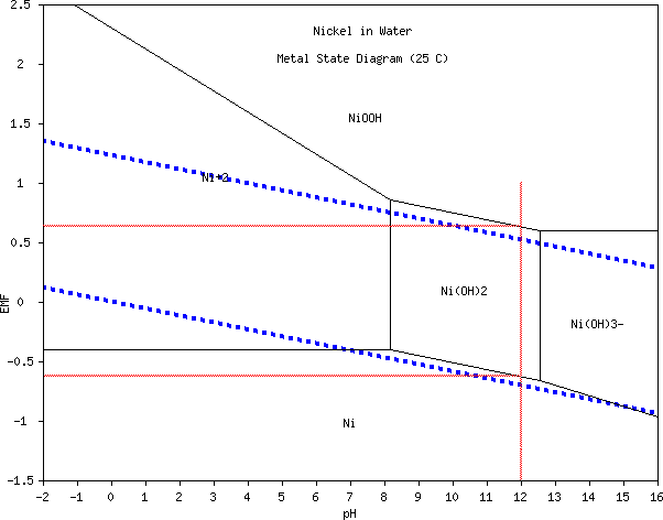 Checking later it
was holding 1.3 gradually down to 1.2 volts when the charge was removed
- for a while. There's still a little self discharge. Maybe I need to
make a proper cell with compacted powders so that it will put out real
current, and holds amp-hours instead of milliamp-seconds. Then IF the
self discharge current is similar and not proportionately increased, it
would take days or weeks to discharge through the area of main energy
instead of minutes. Or it may be that there's a gap somewhere in the
osmium film. (A second coat might make a difference?)
Checking later it
was holding 1.3 gradually down to 1.2 volts when the charge was removed
- for a while. There's still a little self discharge. Maybe I need to
make a proper cell with compacted powders so that it will put out real
current, and holds amp-hours instead of milliamp-seconds. Then IF the
self discharge current is similar and not proportionately increased, it
would take days or weeks to discharge through the area of main energy
instead of minutes. Or it may be that there's a gap somewhere in the
osmium film. (A second coat might make a difference?)
Nickel Pourbaix
(electrochemistry) diagram showing the overall cell
potential of about 1.25 to 1.3 volts at alkaline pHes from 8 to
13
The layers of the cell were:
* Graphite foil (or other sheet or mat of graphite)
* Thin conductive film of osmium doped acetal ester (per very early TE
News issues) painted on the graphite foil
* Positive electrode powder (scorched Ni(OH)2 with La(OH)3 in bean
sauce (thiamin) binder, per very early TE news issues)
* -------------------------------------------------------------
Insulator paper --------------------------------------------------
* Metallic Nickel negative electrode substance (just a sheet of
cupro-nickel (70:30), surface etched with ferric chloride)
The graphite foil sheet is of course the current collector
for the positive electrode. To prevent contact of the graphite with the
electrolyte, the electronically conductive thin film doped with osmium
separates them.
A number of things might be used for the positive
electrode substance. I chose my old nickel hydroxide mix rather than
the nickel & manganese mix to leave manganese oxides and nickel
manganates out of the equation for now.
I chose my favorite heavy "Arches watercolor paper" as the
insulator paper least likely to get a hole in it and short out.
The bottom sheet doubles as the negative current
collector. To get a "real" battery with good amp-hours, nickel foam
filled with minute nickel powder flakes will give lots of surface area
of minute nickel particles in contact with the electrolyte. The bottom
sheet would remain for its surface nickel and as the negative current
collector. The copper in the sheet gives it stability regardless of
charging and discharging of the surface nickel.
The ethaline DES with the (hopefully dissolved) potassium
oxalate wets the interior. One nice thing about the ethaline: it
doesn't evaporate in an open cell like water does. (Say, what is the
solubility of potassium oxalate in ethaline, anyway?)
Negative Electrode: + Nickel Micro Flakes
On the 26th, not seeing any further results, I opened the
cell and sprinkled a little nickel flake powder on the bottom sheet.
After some more charging the short circuit current was at least 5 times
higher. Not that a few tens of milliamp-seconds isn't still pretty
pathetic, but it was more than before.
Electrolyte Mix: + Ca(OH)2
Then I thought that maybe some potassium hydroxide would
help. I'd have to be careful because very much would turn the
electrolyte to pH 14 and the cell wouldn't work. (Metallic nickel
ceases to oxidize at that pH.) First I checked the pH with a test
strip. I was a little dubious about using the test strips in the
ethaline instead of in water. They were hard to wet, but where it
wetted it seemed to give a greenish color indicative of pH 9 or 10. I
looked in the cupboard and saw calcium oxide (CaO, lime) instead of
potassium hydroxide (KOH, caustic potash). That reminded me... in water
lime could only raise the pH to about 12-13 because it's only slightly
soluble. Again, how soluble would it be in ethaline? I decided to try
that instead, and sprinkled a little in. It may have improved the
current a little. Later the pH reading was around 11.5, seeming to be
between the distinct color difference between greenish 9-10-11 and
brownish 12. If the pH had risen to 14, the cell would have quit
working, but it appears Ca(OH)2 is, if anything, even less soluble in
ethaline than in water. It's perfect!
Conductivity: + Conductive Carbon Black... and the Ever Nagging Self
Discharge Problem Explained
The next morning I sprinkled some conductive carbon black
onto the positive powder to increase the conductivity. Initially all
went well. It scaled up the current drive by at least 5 times. Charging
current went from 1-1/2mA to upwards of 6, and short circuit discharge
from under 10mA to over 50 (with an initial reading of over 130).
But soon the cell started to have a lot of self-discharge.
That might be the carbon black oxidizing, or it might be that it simply
doesn't have high enough oxygen overvoltage and will continue to absorb
oxygen or hydroxide from the fluid and release it as a gas. In fact, it
started behaving like so many of my previous cells, showing that (as I
more and more suspected) the graphite not only of the current collector
but of the conductivity increasing powder in the electrode has been the
main cause all my self-discharge problems. Graphite powder or carbon
black works great in non-rechargeable dry cells... but then those use
manganese dioxide instead of nickel oxyhydroxide, which has a lower
voltage. It may be that this can be overcome by charging for a long
period until it's all oxidized, but after several hours it wasn't
looking very promising. (perhaps with addition of more oxalate and
lime?) Well, there are other ways to improve positive electrode
conductivity besides carbon. In fact, just properly compacting the
electrode powder I used in a powerful press, without graphite, might
well make the difference.
Nothing seemed to help after that.
Conclusions
The chemistry seems good. The pH papers worked, so I guess
the DES acts like water in many ways. Of course this was still just a
test cell with unmeasured powders simply sprinkled on and pressed down
by a bit of weight, and the electrolyte mix was equally haphazard.
With properly mixed and pressure compacted substances (nix
on graphite & carbon black!), an optimized mix of electrolyte and
reasonably well sealed, it should be a real battery without notable
self discharge. I expect it would be cheaper and better for electric
transport than anything else out there. It should be higher energy
density than lithium types simply by virtue of having very thick
electrodes (up to ~5mm?) instead of thin film electrodes. Lithium is a
light, energetic element, but the multiple folded-up membranes
separating the many thin films needed to use it in a battery are just
extra weight and bulk with zero amp-hours. And nickel has been observed
to have the highest usable amp hours of any common metal.
There are further experiments that should be tried in
order to obtain the most ideal cells. Mixes of monel (cupro-nickel)
with lanthanum or samarium hydroxide, and various forms of manganese
oxides combined with nickel should all be tried as well as variations
in electrolyte mixture.
And the 2.6 volt (open circuit) nickel-manganese cell with
the manganese negative electrode, worked out in 2010-2012, remains an
interesting development that deserves more experimentation to see
whether or not it may prove to be practical if the electrolyte is
changed to oxalate in ethaline. (I suspect manganese may be something
like iron, that it reforms into larger crystals during charge and
discharge and hence has low current capacity and low actual amp-hours
compared to theoretical. But the zinc powder conductivity additive
seemed to work well. And anyway nickel-iron cells are still made and
used today.)
(Having attained the results I hoped for, I turned back to
other projects. But on the 29th I searched the shop for an electrode
compactor I knew I had somewhere. In the hydraulic press it makes 2"
round "button" electrodes. In that search, I found a box with some
"missing" lab supplies including the oxalic acid I had been unable to
find. There was more left than I had thought. Hmpf! I could have made
my own potassium oxalate after all instead of ordering some. Anyway, I
needed the other things I bought in the same order. I found the
compactor on another shelf.)
Well, this has only taken 10 years! It would seem I had
many or most, but not all, of the essentials for good cells right in
the early times. It took the rest of the decade and a lot of learning
to get the remainder.
Now it needs someone who can put some time into it to do
these things, get it all optimized and ready to produce - I'm spread
too thin with other projects already. Preferably of course someone who
knows some chemistry and is able to measure and quantify. A better
equipped lab wouldn't hurt either.
(What, no pictures?!? Oops.)
http://www.TurquoiseEnergy.com
Haida Gwaii, BC Canada