Turquoise Energy Ltd. News #119
covering April
2018 (Posted May 4th)
Lawnhill BC Canada
by Craig Carmichael
www.TurquoiseEnergy.com
= www.ElectricCaik.com
= www.ElectricHubcap.com
= www.ElectricWeel.com
Month
In
Brief
(Project Summaries etc.)
In
Passing
(Miscellaneous topics, editorial comments & opinionated rants)
- 7CoreValues.org - Plastic beaches and oceans
- US Government: a failed democracy? - Guarded humour
- Project Reports
-
Electric
Transport - Electric Hubcap Motor Systems
* Chevy Sprint: got it running. (YAY!) Complications &
inspirations... Stereo & music - Controller & motor - Clutch
slipping - Another Try at "Sep Ex" Control - Take apart - Motor - Field
Drive DC to DC Converter? - Batteries - Headlights: fixing problems
from long ago - Moving along - Solar charging?
* PM Assisted Reluctance Motors, Improved Performance Unipolar Motor
Controllers(?) & Electric Transport
* Some Nissan Leaf Notes - EV Market
Other "Green"
Electric Equipment Projects
* Carmichael Mill ("Bandsaw Alaska Mill")
* "The Indoor Vegetable Garden" - Year round gardening with LED
Lights! (and other gardening)
Electricity Generation
* Hydro Power: Turbine Shaft & "Spiral Staircase" water wheel
* The Electromagnetic Spectrum, John Bedini & (V)HE Ray Energy:
Ideas and experiments
Electricity Storage -
Turquoise Battery
Project (NiMn, NiNi, O2-Ni), etc.
* Nickel-nickel: How good would it be?
April in Brief
 Halibut Bight/Lawn Hill beach gratuitous image
having nothing to do with anything
Halibut Bight/Lawn Hill beach gratuitous image
having nothing to do with anything
from low tide looking toward my house (wherever it is).
The sand on the lower part of this unusual beach is always mostly
soaked
but it's only 1/4 inch deep or even between the sand grains -
those 'ripples' are actually patterns in the sand. On the upper part
the
rock and sand rearrange themselves with every tide -
in any place rocks one day, sand the next, or sometimes all gravel and
rock.
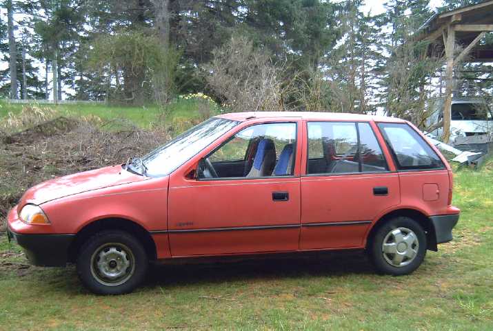 The Chevy Sprint - at the far side of the
acreage under its own power.
The Chevy Sprint - at the far side of the
acreage under its own power.
(Behind-right is the electric Miles truck, presently being kept under
the trailer shelter roof.
And behind-left is part of yet another pile of spruce branches that
hasn't been cleaned up yet.)
In April I did a considerable amount of work on the Sprint
car. I got
it to run right after doing the last TE News (as series wound motor)
and took it up Lawnhill road a way once, as well as across
the acreage a few times. I made several fixes or improvements. Now it
runs great "off road". But the
performance will need considerable improvement before hitting town
streets much less for highway cruising, and so far it's still "push to
back
up" - ugh!
 But in the
process of trying to figure out ways to improve
it, I may have
hit on a potential technical breakthrough: in thinking of how to turn a
series
wound motor into a "separately excited" motor, I ran into a circuit,
simpler than others, that appeared to harness "HE" rays (apparently not
"VHE" rays), which might be used to supply more current to the field
coils. And from there the idea expanded in my head of potentially using
similar circuits to power other
electrical loads from these high energy "short space rays" that
continually shine(?) down on our planet, mainly from the plane of the
Milky Way. However, aside from better theory and in spite of a few
experiments with coils out by the car, I haven't got anything to
actually work.
But in the
process of trying to figure out ways to improve
it, I may have
hit on a potential technical breakthrough: in thinking of how to turn a
series
wound motor into a "separately excited" motor, I ran into a circuit,
simpler than others, that appeared to harness "HE" rays (apparently not
"VHE" rays), which might be used to supply more current to the field
coils. And from there the idea expanded in my head of potentially using
similar circuits to power other
electrical loads from these high energy "short space rays" that
continually shine(?) down on our planet, mainly from the plane of the
Milky Way. However, aside from better theory and in spite of a few
experiments with coils out by the car, I haven't got anything to
actually work.
I now had the 36 volt car
at least running, and I was reminded that Jim Harrington in Victoria
had a 2500 watt, 36 volt to 120 VAC inverter he didn't want. I bought
this from him and had it shipped up. It arrived in record time via the
post office. If there should be an extended power failure I can use the
car to keep the freezer and fridge cold and make coffee, using as many
solar panels as required to keep the batteries charged for these
essential purposes.
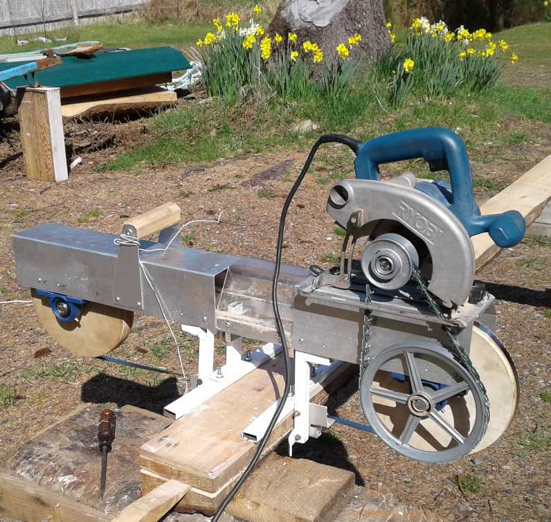 I made one
small stab at the handheld bandsaw mill and
finished the first adjustable band guide. It worked, but the other one
needs doing, and some other parts and mounts need to modified or made
stronger, before it'll be tackling real lumber cutting jobs. Adjustable
band guides are however the key. People say the trouble with bandsaw
mills is that you're always adjusting them. Instead of
trying to achieve what others have failed to do - make a small bandsaw
mill that doesn't need adjusting - the thumbscrew adjustments will
allow fine adjustments in a moment "on the go" in the middle of a
cut, without removing the saw from the work.
I made one
small stab at the handheld bandsaw mill and
finished the first adjustable band guide. It worked, but the other one
needs doing, and some other parts and mounts need to modified or made
stronger, before it'll be tackling real lumber cutting jobs. Adjustable
band guides are however the key. People say the trouble with bandsaw
mills is that you're always adjusting them. Instead of
trying to achieve what others have failed to do - make a small bandsaw
mill that doesn't need adjusting - the thumbscrew adjustments will
allow fine adjustments in a moment "on the go" in the middle of a
cut, without removing the saw from the work.
I would like to get it really working well and cut the
spruce cants blocking my driveway into lumber and put them away before
they start to deteriorate.
On May first someone said there is already such a thing as
a "handheld band saw". I'll be looking up that term to see what I can
find. I certainly came up blank in previous searching, but sometimes
it's a matter of knowing the exact term.
The indoor garden has
continued to bear fruit... I mean vegetable greens... from the January,
February and March boxes but I didn't plant a new box in April, only
garden and greenhouse seedlings, and tomatoes. It's getting to the time
of year one can grow crops in the greenhouse and outside. I may make an
improved version indoor garden for next fall.
 The LED indoor garden April 20th with January
(leaf lettuce... and a potato), February (romaine) and March (spinach)
The LED indoor garden April 20th with January
(leaf lettuce... and a potato), February (romaine) and March (spinach)
box plantings, as well as tomato pots and remaining seedlings not yet
planted in the greenhouse or outside.
The lettuce has good flavor.
In monthly conference calls I've been following the
progressing documentation work on "planetary management", "evolution of
democracy", "social sustainability" and "the seven core values of
social sustainability". Two of the participants have just created a web
site called 7CoreValues.org .
(I got invited because of my "HandsOnDemocracy.org"
web
page.)
As the weather improved I also did a lot of work cutting
up and burning branches from the fourth spruce tree, cut down last
fall. The larger branches seem to make good firewood - I'm already
burning
those from the other three trees, which were cut early last summer. But
I heavily discounted the time it would take to clean everything up.
It's good exercise
and once a branch pile is burning it seems irresistible to keep cutting
and feeding it day after day until the branches are gone from an area,
but while doing that I keep thinking of the projects, gardening,
housework, paperwork
and other things getting farther and farther behind. It will be nice to
get a year ahead on firewood at some point so I'm burning wood that has
had a year or more - two summers - to dry out.
In Passing
(Miscellaneous topics, editorial comments & opinionated rants)
7CoreValues.org
I've mentioned the new ideas of the core values of social
sustainability before - values that everyone in every culture could
agree on as being primary over other values. From these a morality (set
of rules of human interaction) will gradually develop and ethic
statements or principles (the "how to" for fulfilling the rules or
morality) will be derived to serve individuals, families,
organizations, societies and global civilization. Now there's a web
site
being
put together with them, per the title. Someone is putting together a
postcard with a slogan to introduce it:
"It's not hard to make decisions once you know what your values are.
"LIFE - Quality of Life - Growth - Equality - Empathy - Compassion -
Love of Humanity"
So far the site has just basic introductions to Planetary
Management, Social Sustainability and Values Based
Design Teams. There is a page with a few links to resources. Many
additions are intended or in the works. The family will be a prime
focus as the home is the basic institution that carries forward what is
learned and the values from one generation to the next.
If it is new and may attract little interest at the
present time, in coming years and decades people will be scouring the
web for info to help solve a perplexing array of societal, political
and economic problems. They will eventually look here and find some
positive values, approaches and other answers.
Plastic Beaches and Oceans
Apparently I am neither the first nor the only local
resident who picks up plastic off the beach. I'm told it's not nearly
as bad now as it was after the Japanese Tsunami of 2011. Also that the
west coast of the island - open to the Pacific and with no one living
there - is much worse than here on the east coast. Might we dare
hope some of those islands of floating plastic "the size of Hawaii" in
the middles of the oceans are shrinking too? But no one is out there
cleaning them up, so it depends whether the currents ever unlock them
and send them to some shore - like our west coast.
Is anyone in Charge?
One day in April US President Trump said what most of the
world so wanted to hear: That the USA had accomplished what it set out
to do [whatever that was] and would be withdrawing from Syria, to leave
the tangled affairs of the middle east to others. No more American
blood would be spilled. He was then reportedly incensed when his top
general told him it would take over a year to exit that country. (2000
troops was it? - about the number of people transported, with their
hundreds of vehicles and freight, every two hours by each BC Ferries
vessel?) If the president is really the nation's leader and your
commander in chief, this was pretty
blatant refusal to obey an order and tantamount to treason.
On cue there was then a reported "chemical gas attack" in
the last remaining rebel held area near Damascus, which everybody from
everywhere as soon as they went there and checked it out quickly said
there was no sign had ever taken place - no bodies, no hospital
patients, no chemicals. In the USA this (this... what?) was immediately
pinned on Syrian president Assad. (After all, Assad must be doing these
inflammatory, pointless attacks on his own citizens, all in rebel held
areas, to have been baselessly accused of them three times! It's the
stock narrative!) And what possible result could they have had? Only to
keep
the USA from leaving Syria in peace! (Most of the rebels in this
last enclave had already surrendered and were being bussed to another
part of Syria per the surrender agreement. A last small group held out
long enough to fake this little stunt. Now, Quickly, Attack Assad
before any more inconvenient facts leak out!)
The USA responded with a real (but forewarned) missile
strike against Syria, Trump tweeted against "that murdering ___,
Assad", and it was said that it would be a long time before the USA
would pull out of Syria. Conveniently a fleet of warships had just
arrived in the Eastern Mediterranean just in time to
launch the strike. The situation is perhaps confused by the amazing and
also conveniently timed and co-ordinated French and British
participation. But no real explanation
for the apparent abrupt reversal of stated US policy by its elected
leader has been offered so far.
Is the USA a failed state? Or at least a failed democracy?
The elected leader, whom we've long suspected isn't really in control,
has just demonstrated it by giving a direct order which was disobeyed
or circumvented, and then by changing his mind or having had it changed
for him - caving in. A bunch of brazen faceless, unelected, tinfoil hat
wearing civil service boss wackos with various conflicting agendas
appear to be in charge of what is laughingly called "US foreign
policy". GW Bush said on the initial invasion of Iraq "It's not about
the oil", but when Trump said the USA was going to pull out of Syria,
someone of note
said "We took the oil! We've got to keep the oil!" If it's an affront
to all decency, at least some honesty is coming out after 15 years. And
what's it all for anyway? In another 25 years we'll be using very
little of the stuff compared to today - mostly for plastics - much to
the relief of the environment and the populace.
Or was Trump even serious about getting out of Syria and
the Middle East in the first place? Whatever... along with their
victims, the people of the USA apparently aren't going to be permitted
to
live in peace until their government falls apart. perhaps until there
isn't enough of a productive public left to carry on giving all their
first fruits (over 50% of the entire US government budget) to the
military while everything domestic is permitted to fall apart through
neglect. How would 30 years of peace and relative tranquility
transform that nation? They certainly haven't had it in a century. And
what country would really attack a peaceable
USA? Its existential threats are indeed from within.
---
Funny, it seems "slaughter" is just "laughter" with an "s" on it. [per
Benny Hill, "The Film Editors" - youtube]
Is this why those who order deadly attacks think so lightly of doing it?
Can you send your regards without first sending your gards?
Do
choices have percussions before they have repercussions?
When cancer is in remission has its original mission ended?
(Well, we always hope so!)
People wish to fulfill their aspirations, but to filfull their morning
coffee cup.
"in depth reports" for
each project are below. I hope they may be useful to anyone who wants
to get
into a similar project, to glean ideas for how something
might be done, as well as things that might have been tried or thought
of... and often, of how not to do something - why it didn't
work or proved impractical. Sometimes they set out inventive thoughts
almost as they occur - and are the actual organization and elaboration
in
writing of
those thoughts. They are thus partly a diary and are not
extensively proof-read for literary perfection and consistency before
publication. I hope they add to the body of wisdom for other
researchers and developers to help them find more productive paths and
avoid potential pitfalls.
Chevy Sprint
Car - Forklift Motor & Fixed (8.9:1) Reduction
Aside from getting the car to
run, one pleasant thing that happened when I connected 12 volts and
brought the car's electrical system back to life was that the stereo
(after releasing and plugging in the removable faceplate a number of
times) was
very nice. This 1990 car's stereo had SD card and USB memory stick
plug-ins. That's pretty impressive when USB 1 wasn't created until
maybe
2002. I copied some files of instrumental music I'd written and played
from
1999 until about 2003 and played them in the car while I worked.
Save the Music!
As a side note, that inspired me to boot up the old Mac OS
9 system and turn all my music, written in the now unavailable
"Overture 2" music notation software, into MIDI files which, if they
lose text and many nuances, can at
least be imported by other notation programs. While there was never any
particular urgency, it was important to do this before I lose my last
computer that will run Mac OS 9 & Overture 2 and hence lose most of
the music I wrote, mostly from 1999 to 2004. I don't have printed
copies of some of it. They're now on a USB
stick. Now I must upload them to the web!
Most of Antonio Vivaldi's music survived until the 20th
century only by the scores being thrown in drawers in some back storage
room in a church for 2-1/2 centuries. Someone checked somewhere with
someone before throwing them out and somebody bought them all... and
what fabulous music it is! (Actually I think there was a second stash
found after that, and an occasional other score has turned up now and
then.) Vivaldi's music was very popular while he
was alive. He was JS Bach's inspiration. No doubt all I have to do
today to have Craig Carmichael's instrumental music preserved is get
around to uploading my music to some archive. I might have become
popular if I'd kept at it, but I had a hard time getting players
together and I turned to other pursuits.
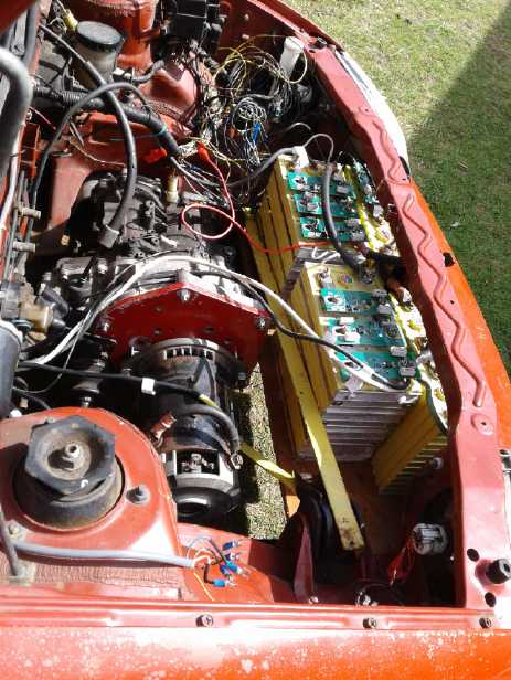
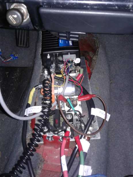
Motor Controller and Motor
The motor controller
assembly just sitting on the center hump
inside the car. (It needs fastening down and a cover.) Right
behind is a big hole that the gear shift stick went down into,
which was convenient for running the heavy wires through.
(A coffee cup holder will cover that hole.)
The red button is the obligatory circuit breaker trip within
reach of the driver - perfect!
 Somehow I had
got the idea that a "series wound" type of
motor with four terminals, 2 for field coils and two for armature
coils, was pretty much the same thing as a "separately excited" motor
also having four terminals. The motor controller however didn't think
so. I couldn't get it to play ball. The resistance of the "series
wound" motor's field coil was so much lower than that of a 'regular'
separately
wound field coil that the controller had trouble modulating it and
considered it a "short circuit". It accordingly went into error mode
and shut off the power. The same reason both types of motor had four
terminals was so the field could be reversed without reversing the
armature, to get it to run backward. And (I assume) they are really the
same
except for the size and number of windings in the stator (field) coil
being drastically different.
Somehow I had
got the idea that a "series wound" type of
motor with four terminals, 2 for field coils and two for armature
coils, was pretty much the same thing as a "separately excited" motor
also having four terminals. The motor controller however didn't think
so. I couldn't get it to play ball. The resistance of the "series
wound" motor's field coil was so much lower than that of a 'regular'
separately
wound field coil that the controller had trouble modulating it and
considered it a "short circuit". It accordingly went into error mode
and shut off the power. The same reason both types of motor had four
terminals was so the field could be reversed without reversing the
armature, to get it to run backward. And (I assume) they are really the
same
except for the size and number of windings in the stator (field) coil
being drastically different.
After days of puzzling, I finally suspected this was the
problem on the evening of the third. I
disconnected the field wires at both ends, and wired the motor with the
coils in series - just as it had been when it pushed the car, connected
straight to batteries. The armature drive now drove the whole motor. It
seemed to spin okay and I took the jack out from under the wheel. I
pushed the car to the front of the garage, got in, and pressed on the
pedal. It backed up smoothly to the far end. Finally it ran nicely!
I don't know why but I'm somewhat amazed that my
slide-button-potentiometer 'electron pedal' made years ago now has been
working flawlessly, as shown on the smooth "throttle" readings on the
programmer as well as there being no power glitches during driving.
At least (and at last) it was running. But the plan had
been to use the
motor controller's field drive to select forward or reverse. I was left
with having to change the wires at the motor to change direction. It
could go forward or backward, but not both. Well, one could always be
sure to park facing uphill so the car would roll back out of its
parking spot. That or "push it to go backward" sounded easiest! (Keep a
peevee in the car to pry it with. Or a wrench to rewire the motor
twice.)
First I tried to open the motor to see about changing
things inside. Instead I almost wrecked it. Later I tried to come up
with plans to make it work like a
"sep-ex"
motor without actually changing the motor.
Project Slipping Backward
(April 4th) I backed the car out of the garage. A separate
problem
presented itself. When it went to climb a bump, something was slipping.
I could hear the motor turning but the car wasn't moving. This had
happened before I got the right Lovejoy connectors and I shrugged it
off as being one must have come loose and been slipping on the shaft.
Now they were
solidly in place, spline on one and keyed slot on the other. What could
slip? It finally hit me: my jamming up of that internal clutch in the
transmission had been inadequate. Evidently just because I couldn't
budge it with a big screwdriver with good leverage didn't mean it
couldn't slip once the transmission was full of oil and the load of a
whole car was on it. Could using heavy gear oil instead of "automatic
transmission fluid" have been a mistake? Maybe that was formulated
specially to make the internal clutches stick? Or was it just not
jammed stiffly enough? It looked like I'd have to take the whole thing
apart again. A big setback from a small cause!
Another Try at "Sep Ex" Control
I wasn't entirely convinced that the "sep ex" control
method couldn't work. Perhaps one could put a small resistor in line
with the field coil so that the controller wouldn't see it as a "short
circuit"? How about .1 ohms? 25 A ^2 = 525. 525*.1=52.5 watts. Ouch!
The "small" resistor would have to be pretty huge! Maybe instead of
running heavy (#10 AWG) wires cut as short as possible (5'), I could
run skinny wires, a long length coiled up? Maybe a long chunk of #16
gauge cord? Would the extra inductance from a coiled wire fry the
controller? Well, it was already driving a motor coil - an inductor.
Should be safe, then?
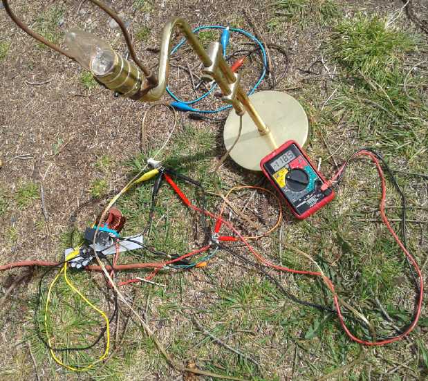
So I found a 19 foot piece of #16 extension cord and tried
it out. Nope. It still tripped off just the same, using either set of
coils as the "field". I measured its resistance. (by shorting one end
together and putting 1.00 amps through it from one terminal to the
other at the open end, and measuring the voltage.) It was 247 milliohms
- 0.247 ohms. The field coil was only 13 milliohms; this was 20 times
higher. Just how high, in miiliohms, do you have to go before it
doesn't register as a "short" in the controller?!? I should have
checked the "motor resistance" reading on the programmer.
Now, what about that clutch? Ugg! I put the motor wires
back at "series wound" and "forward". Between the slipping motor and
pushing with the other foot where it slipped I got it back into the
garage.
But I wasn't quite done. I returned to the "sep ex"
experiment in the evening. I put the "field" drive wires on the
armature. It read "100" - a whole ohm. It had gone from reading "0" to
a higher figure than was real. It should have been under 1/2 an ohm. I
turned the "Max Field" current down from 25 to 15. This time when I
pressed the pedal, it didn't quit. But the drive was feeble and the car
only sort of wanted to move. I changed it to the "field" wires on the
"field" coils. Here the resistance read "0" again, even tho I knew the
wires were 1/4 ohm. It worked just a bit better, if at all. I upped the
"Max current" to 20. Here the car would roll feebly back and forth on
the level cement, with very high armature currents. I went up to 21...
22... 23 amps, and here the controller tripped off again.
Then it started saying there was no contactor relay. The
voltmeter confirmed that sure enough, with all the tripping off of the
contactor while the highest of currents were flowing through it, no
doubt there was a lot of arcing inside, and the contacts no longer made
contact. Yet another thing to fix or replace before I could get any
farther! (The next morning the relay was okay again. But for how long?
Oops, not long - it quit again.)
I suppose that if the controller would put similar amps
into the field coils as into the armature coils, it would work fine. If
it would put in even 40 or 50 amps (reliably) instead of 15 or 20, it
might do it. That gave me the thought of a way that might just
conceivably make it work. That would be to open the motor and see if
either set of coils - those of the stator or of the rotor - were made
up of multiple identical coils connected in parallel.
If there were for example four wires inside going to each
of the field connection terminals, then they must be wired in parallel,
and they might be rewired in series.
Then 20 amps would flow through all four sets instead of 5 amps through
each. (And the motor controller field driver would probably handle 4
times the resistance better.) Then 20 amps would give the same magnetic
effect as 80 amps does now. That might make it reasonably
similar to what one would find in a "separately excited" motor.
Or if not the stationary windings, how about the armature?
This motor has 4 brushes instead of 2. Could there be in effect two
sets of armature windings electrically in parallel? If one could rewire
them in series and drove them with the field drive, then the magnetism
would double for the same current (which would be attained at twice the
voltage). 20 amps would be like 40. Might that be enough?
Take Apart
By evening of the 5th there were three compelling reasons
to take everything apart:
* The slipping clutch inside the transmission needed to be made solid.
* The poorly functioning contactor, doubtless with burned contacts. I
hoped I could fix it.
* The motor would be examined to see if any beneficial rewiring was
possible. (Without rewinding half the motor coils!)
and
* While I was at it, the Lovejoy coupler on the motor was rubbing a bit
on the motor plate, making noise. While it was off I could turn it down
just a bit more on the lathe.
* And I had missed putting the rock shield back under the transmission
oil pan - good time to do it.
That wasn't going back to square one, but it was certainly
a few squares back! I wasn't looking forward to reopening the
transmission that I had filled with 2 liters of heavy gear oil. Perhaps
it was time to switch to another project for a while? In a fit of
determination or desperation, I disconnected and disassembled
the whole front end in an hour before bedtime: motor, batteries,
battery shelf, motor plate, and transmission. Maybe it wouldn't be so
bad. And maybe I could just tip the transmission up so the oil stayed
at the back while I took off and pulled out all the pieces?
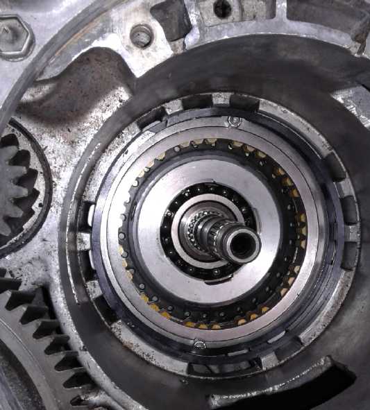
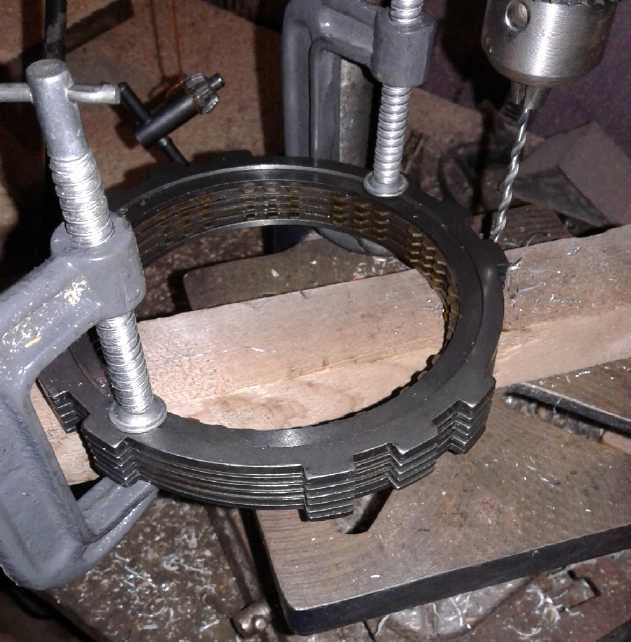 I tackled the
transmission the next morning. The oil stayed in the pan at the bottom.
But I could see it had wetted the gears and interior. That was
reassuring. I pulled out the clutch plates and drilled two holes
through them all (carefully aligned and held with C-clamps), then put
two #8-32 machine screws in through them with locking nuts.
I tackled the
transmission the next morning. The oil stayed in the pan at the bottom.
But I could see it had wetted the gears and interior. That was
reassuring. I pulled out the clutch plates and drilled two holes
through them all (carefully aligned and held with C-clamps), then put
two #8-32 machine screws in through them with locking nuts.
Rear of Transmission with bolted clutch plates.
 The circlip ring to hold it in place wouldn't go back in
the same slot because of the bolts and nuts, but there was another slot
just a little farther out and I more or less got it in there - except
in a couple of places. I didn't want to "cludge" it like that (any more
than I had wanted to "cludge" the clutch closed in the first place),
but
there wasn't room to do much else. (Which is also why I didn't use
bigger screws.)
The circlip ring to hold it in place wouldn't go back in
the same slot because of the bolts and nuts, but there was another slot
just a little farther out and I more or less got it in there - except
in a couple of places. I didn't want to "cludge" it like that (any more
than I had wanted to "cludge" the clutch closed in the first place),
but
there wasn't room to do much else. (Which is also why I didn't use
bigger screws.)
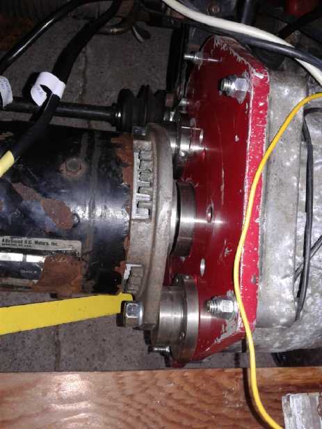
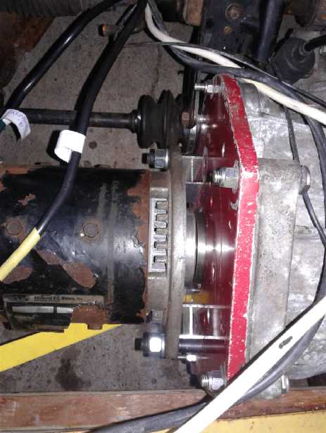
With the transmission out in the light I could see the
Lovejoy connector could be moved in another 1/2" along the shaft, which
would move the motor in 1/2 inch and should take care of the rubbing. I
put the rock guard on the
bottom and put the transmission back in the car by mid afternoon.
7th: I disconnected and removed the contactor relay, and
took it in the house. Once I had it at the bench I noticed there were
two screws holding a cover over the contacts. All I had needed to
do was open the cover, without dismounting it. The contacts looked like
new. I guess the controller shuts off the motor drive currents just
before it opens the contactor. Then I realized the problem was that it
had a 36 volt activation coil and I was still running the car at 24
volts for testing. It didn't have enough pull to be reliable. If I left
the cover off
and pushed just a bit with my finger as I turned the controller on,
it would click into place.
Motor
At this point a sane person would have just put the motor
back on the
car and ordered a giant DPDT contactor relay to reverse the motor
direction
for backing up the car. But not me. Oh, no, I had to see if it could be
done better, if there was some way to make it from a plain "series
wound" into a superior "sep ex" type motor. It's
impractical to do regen braking with series wound, whereas it was
built into the sep-ex controller by driving the field coils in reverse.
I put it on the bench in the shop and tried to get it
apart. I got the ends unscrewed (one bolt broke off in the hole - 3 out
of 8 now with someone else's previous breaks), but I couldn't get the
bearing off one end nor the fan off the other, so I couldn't pull the
rotor out. I could sort of see inside. There's "flat" and "oval" wire
as well as round, but I'd hardly call this wire. More like flat copper
bars bent to the desired shapes. I could see why it was said these
motors could take a lot of abuse. There were indeed four stator
("field") coils. The question was then whether they were in parallel
and could be changed to series, or if they were already in series.
There only seemed to be one copper bar connected to each terminal. That
suggested they were already in series. Rewinding those heavy coils with
regular wire seemed like a poor prospect.
Each of the four coil cores seemed to be held onto the
inside
of the "can" with two bolts. I could remove those and the fan and all
would slide right through... everything would work except for the two
terminal bolt heads connecting the "wires". I took the nuts off one,
but
I couldn't seem to get it out. I had the impression the wire was welded
on. Doubtless easy to remove without the rotor, but
then getting that out was the whole problem.
Then I thought if I put the motor on the hydraulic press I
could press the end bearing out via the shaft. Since the end bell would
be supported
all around, nothing would break. Unfortunately... wrong! As I increased
pressure I heard a couple of noises and thought the bearing must be
starting to come out. In fact, the entire end bell was caving in. When
I noticed its concave shape, I released it. It didn't quite come
completely back out. The noises were the
brush holders cracking. Somehow the brushes were still held, but they
were no
longer flat against the commutator. Yow! And then I found a piece of
the rim of the fan had broken off somewhere in the madness. Now if the
RPM gets too high the fan just might fly into pieces. I put it back
together (cleaning and oiling the remaining bolts) and onto the car. I
reconnected the batteries. It still ran. At least now the car ran
without slipping -
Hurrah! And the rubbing sound had quit. But I now have misgivings about
the motor's reliability, efficiency and longevity.
Moving along, I checked currents on the 10th. A slow roll
on the level garage floor said around 100 amps of motor current (as
read by the programmer on "monitor"), which measured as around 25-30
amps of battery current (clamp-on DC ampmeter). If I stuck a 2x4 board
in
front of one wheel, it couldn't quite climb over it without just an
inch or two run at it. (This should improve when I raise it to 36
volts?) This stall involved around 180 amps in the motor or 84 amps
from the batteries. (I limited the motor current to 200 amps in the
controller programming.) Since the battery was just ~25 volts, these
translate to 25*25=525 watts (3/4 HP to 1 HP) to roll and 2100 watts
(2-3/4 HP) to stall at or climb over the 2x4.
That's probably not too dissimilar to performance I was
getting with the
Electric Hubcap motor with the clutch and flywheel when all was going
well with that setup in 2016. But then I had no level concrete, just
hilly
lawn, so it's hard to compare. And on this one I haven't yet gone from
24 to 36 volts yet.
Take 2: About the 14th I started thinking that I hadn't tried very hard
to get the field coil connection bolts out before I tried
unsuccessfully pressing out the bearing. If those bolts could be
knocked loose, the insulator might come loose and allow the bolt to be
turned sideways and removed. Then the fan would fit through the body
and it would all come apart.
Maybe to make it a "sep ex" instead of a "series wound"
the field coils could be rewound to have, ideally, say 6 times the
length of wire of 1/6 the cross section. That would mean 20 amps -
which the field drive in the controller can manage - would give the
magnetism that 120 does now. If I can get it apart. Then if nothing
else, the car would at least back up. But I suspect there would also be
improvement in performance.
Field Drive DC to DC Converter?
On the 17th after the test drive on the road, a new idea
occurred to me. The objective of rewinding would be to attain the same
magnetism with lower current and higher voltage. But it would be
essentially the same power; it was just in how it would be used.
How about a DC to DC converter? The field drive already
produced pulse width modulated (PWM) pulses of current. Let the outputs
from the field drive build up a higher voltage, then when it was enough
convert that down to lower voltage, from which the motor field coils
could draw their higher current. Could it be done bidirectionally?
Could it be done with passive components? Feed the pulse drive through
a coil. Coils allow voltage across them instantly and then current
"gradually" starts to flow, opposite to a capacitor where current flows
before voltage can start to "gradually" build. Both devices can store
energy.
The motor coils measured 78 microhenries (field) and 124
uH (armature). I had a 570 uH double coil (bought for the unipolar
motor controller). Presumably then the coil could store 570/78 ~= 7.3
times as much energy as a magnetic field than the motor field coil -
almost the 6 to 1 ratio I had thought might be ideal. It didn't seem to
help.
A DC to DC down converter usually puts a pulse through a
coil. The coil separates the input voltage pulses from the lower output
voltage to prevent excessive "short circuit" current
draw from the (higher voltage) pulses across the voltage drop to the
(lower voltage) output. The current from the pulses/coil then goes into
a capacitor that builds the output voltage to the desired level. A
feedback circuit of some
sort tells the pulse maker when the output (capacitor) voltage is too
low so it will provide another or longer pulse(s) of current to bring
it up to
the desired level. The motor controller field drive already puts out
pulsed current. We're not too concerned with feedback or the exact
output voltage being attained. And here (ideally) it has to be
bidirectional. So coils
and capacitors by themselves might just do the job.
With the coil by itself not appearing to do much, I hunted
down a non-polar 115 uF ("motor start") capacitor to 'hold the output
voltage', put
wires and lugs on it, and put it across the motor field, with the 500
uH coil in series. It seemed like the car was just about to start
moving - in either direction - when the field drive, tho now limited to
15 amps, would shut off the controller. Was it a little better, or was
that just my imagination? 115 uF was pretty tiny for storing energy
compared to the heavy load of the motor coil. Might I have some much
bigger capacitor
that wouldn't quickly blow?
And might a bigger coil prevent the controller from
tripping off? I wired up the double 570 uH coil pair in series. In the
weird world of inductors it read 1800 uH (1.8 mH) instead of about 470
on my meter. The programmer still said "0" ohms. It still tripped off
before the car would start to roll. To limit the current, the inductor
has to match the pulse frequency. If it's too small for the
frequency it acts like a short circuit. Options are to raise the pulse
frequency (or decrease the pulse width) - not an option here - or to
use a
larger inductance. Perhaps a millihenry or two were way too small for
the frequency? Maybe it needed 50 or 200 or 1000 millihenries?
Next day (21st) I thought I'd try something else a bit
radical. I put the coil in series with the armature coil and drive.
Again the car only almost seemed to want to move - not much change
there. But very soon, smoke came out from under the hood. One of the
wires to the coil, selected long ago for another purpose, was only
about #16 AWG and the insulation was burning off of it. I should have
been
able to predict that in a 200 amp circuit, but I thought it would last
through a quick test. (Somehow that seemed to end that line of testing
despite a new, fatter wire.)
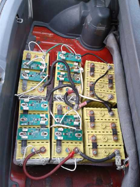
Batteries
I got the batteries mounted some time in the early part of
the month. I covered the details of figuring out the arrangements last
month. The front ones still need a proper cover and tie-down, and they
all need their chargers installed.
The lithium cells really
put out about 3.2 volts under
load. So a "12 volt" lithium battery is really about 12.8 volts until
it's getting low. So I variously call a "24 volt" lithium battery 24,
25, or 25.6 volts, and a "36 volt" one 36, 38, or 38.4. All depending
how exact or explicit I mean to be. The "96 volt" Swift was really a
little over 100 volts (102.4) and as much as 109 on the voltmeter while
driving when well charged. For simplicity I call it 100. (The Sprint
has been measuring around 40.0 standing and 38.9-39.1 in motion.)
I started thinking about all those sessions drawing many
tens of amps if not 100 out of the lithium batteries. Some were still
unconnected, but they had been shuffled around so I wasn't sure which
had been used. I took the four
chargers handy nearby and started charging some of them. After enough
time I checked voltages. A lot of the cells were around 3.3-3.4 volts.
But I found one at 4.0 and one at 4.25. They're supposed to stop
charging when they hit about 3.8, but they weren't balanced. Generally
a lead-acid charger will stop at
14.4 volts, which should be 3.6 volts per cell. But I was beginning to
suspect that there were not just two but many cells that would refuse
to rise above about 3.35. If 3 cells wouldn't rise out of 4 in a 12
volt battery, then the fourth cell would hit 14.4 - 3(3.35) = 4.35
volts or even more. Over 4.2 volts it could be ruined - or worse, catch
fire or blow up. So even for 12 volt charging those little BMS shunt
circuit boards were really a good idea. And what if none of them would
rise up and they all stayed at 3.35? How would the charger know when a
battery was charged if it wouldn't rise up to 14.4 volts? Wouldn't it
just keep pumping juice in until something blew? There were some
pairs of wires connecting all the cells and BMS boards together in the
Swift. Somehow they must have told the charger when to shut off?
I wasn't liking this. I set a timer to remind myself to
check every 1/2 hour while the chargers were on. None of them said
"finished" and shut off by itself. If I told them to charge at 2 amps
instead of 10, the voltage of the cells actually dropped and stayed
lower.
I opened one charger up to see if there was an adjustment.
If they would shut off at, say, 3.5 volts per cell they should be
pretty well charged without risking one cell going over 4.2 volts.
Nope, no adjustments. (I wish I had bought more of the type that had an
adjustment trimpot that Canadian Tire used to have, which I set to 14.2
for NiMH batteries. You don't know whether they have one when you buy
it - you only find out later when you open it and try it, and by then
they're gone from the stores. But then those ones were
only 4 amps.)
I turned on the 12 amp charger for the lower 12 volts in
the hood compartment again on the 10th. Last I checked most of the
cells were at 3.33 to 3.42 volts. But one on one battery was 3.8 and
one on the other was 3.7. These are about as high as you'd like them to
get, but the limit is 4.2, so I left it on. I didn't check for a while
while I was working in the car, and when I did, the charger had shut
itself off. Yay! The two high cells had gone down somewhat after the
charging was finished. I hope none
got above about 4 volts before the shutoff. (Come to think of it, I was
measuring 13.6-13.8 volts at the headlight switch in the car when
checking it.) The next time I charged it the cells seemed more even.
Perhaps they mostly just needed some equalizing after sitting around
for months? Some would doubtless have higher self-discharge than others
and so would be lower.
Charging on the 15th with all nine batteries installed, as
I
checked I added a BMS circuit board to each battery that seemed to be
going to a notably higher voltage than others in the same set. There
weren't enough to go around, but that should probably do the trick.
But it seemed senseless to have the chargers blasting out
and
heating up BMS board resistors until you could smell the heat, just to
get up to their arbitrary 14.4 volt setpoint when the cells were
already all charged. Then it occurred to me that one could drop the
voltage by .6 volts or so with a diode. That with a resistor across it
so the chargers would sense that a battery was present. (Hmm... those
10
amp chargers don't need the resistor - big sparks if the clips touch.
The 12 amp ones do.) Car alternator diodes with big heatsinks should do
the trick.
While on the subject, I somehow had the impression that
the small 40 AH lithium cells were lighter for their storage than the
100 AH
ones, which weighed about 31-32 pounds for a set of four making 12
volts. So I finally weighed a set of the smaller ones. 13 pounds.
Multiply by 2.5 since they were .4 of the amp hours: 32.5 pounds -
virtually the same energy density!
And BTW, what happened to lithiums having energy densities
of over 100 WH/Kg? I get 12.8v*100 AH= 1280 WH. 1280 / (31 lbs / 2.2046
lbs/Kg) = 91 WH/Kg. Well that's actually pretty close, and supposedly
over double what lead-acids have.
The 100 AH, 12 volt NiMH.s were about
40 pounds, making them 66 WH/Kg - about 4/3 heavier; for the Sprint
they would have been 400 pounds instead of a bit under 300. Six ~~380
AH lead-acid golf cart batteries for similar or less effective storage
would have been around 700 pounds.
I wondered also how nickel-nickel would fare, and trying
out a
few fuzzy redox calculations I decided that in practice it might be
roughly
comparable to lithium rather than higher energy per weight. But in
principle they should be cheaper, safer and less finicky. And last
forever. (If one
could get nickel-air to work, they would be really fantastic - double
to triple the energy density.)
Headlights: fixing problems from long ago
Long time diligent readers of TE News with great memories
may recall that I
took apart the dash console to change the wiring of the headlights some
years ago. The common connection to high and low beam was +12 volts
instead of ground, and the low and high beam drives thus both went to
ground. This was reverse polarity for LED headlight 'bulbs' I had
bought. (I suppose they didn't think polarity mattered in 1990 before
bright LEDs were invented.)
It was an endeavor I soon regretted. A "daytime running
lamps control unit" ("DRL") circuit that wasn't supposed to be in the
1990 Sprint according to the Chilton shop manual (and wasn't
mentioned at all in the Hayes one) kept the rewiring from working
properly. I put the halogen bulbs back in and tried to wire it all back
the way it was. But that didn't seem to help either. I assumed I must
have fried the "DRL" circuit, but I didn't know where it was. The
console has been apart ever since. Now that I was getting the car
going, I decided it was time to try and get it working again.
But this one time when I tried it, the headlights came on
when
the key was turned to "run" position. Apparently the "DRL" circuits
were working after all. But nothing happened when you pushed the
"headlights" button, and the high beams only came on when you pulled
the lever to "flash" them. I started thinking that might be good
enough... because the lever was sticking in the "flash" position to
keep the high beams on. But the
next day I tried again, and as before there were no headlights at all
except high beam "flash".
I started with the "headlights on" button. It made a
ground. Finally I got a paper clip and stuck it into the connector the
light switches plugged into. Ground when on. On the other side of the
same connector, same pin... no ground! I unplugged the connector
(looked fine, no corrosion) and plugged it back in. This time there was
ground on both sides. Success... except still no headlights!
I went back to the manual and looked at the DRL circuit
"black box" again. The parking brake switch went into it, but it didn't
run the parking brake light. Why was it there? Suddenly I suspected and
checked: sure enough, if the parking brake was on, the headlights
turned off! (I much prefer "parking brake on, car won't move",
confusing tho that can be. More easily done with electric than gas!)
Luckily I had had the parking brake off the previous day so it had
worked,
or I'd never have figured it out!
So, it would minimally "work" as it was. (Of course, the
sticking "flash" switch would probably pop out with road bumps.) But
surely it was
just one wire somewhere? The one that I had just "fixed" at the
connector. From there it went into that almost inaccessible high-low
beam switch on the steering column. But the wire there was a different
color, so there had to be another connector somewhere in between.
Finally I realized the biggest problem. It wasn't that I
was working in a poorly lit garage. It wasn't that I was inside a dark
car in that garage. It wasn't that I was under the dash where there was
almost no light. Well, it was all those, but it was also that
everything was colored the darkest blue-grey or black. I had a table
lamp in there with me (bare LED bulb - I must have dropped it, knocked
it or picked it up by the bulb over a dozen times by now - not to
mention leaving it with the bulb touching plastic or lying on the
upholstery -- try any of those with incandescent!), but one
could only see what it was shining directly onto. All else was dark
shadow or glare in the eyes. Finally I picked up the light and instead
of trying to find a
better spot to set it, I moved it around to see as I traced where the
cables from the steering column went. The molded nylon fuse block also
had a bunch of connectors around the edges, and the high beam switch
wires went to one of these. I pulled it out and found one badly
burned connection pin with melted nylon surround. Somewhere in the
attempt to change things long ago I must have shorted it and got it
hot. I tried to poke in a jewellers screwdriver and scrape the
contacts. I doubt I did much but when I plugged it back in the
headlights worked.
So at long last I put the console on the dash back
together, and called it a [wasted] day. I had some thought of going on
into the instrument panel while it was all apart and putting the Curtis
"multifunction" display into it where the "engine temperature" or
"fuel" gauge was. But it was probably safer just to mount it up on top
somewhere. Anyway I don't have the right socket to plug it into yet.
And it was a relief to finally have the dash back together.
The better part of valor, way back then, would have been
to try to take one of the LED headlight "bulbs" apart and see if I
could swap the wires inside (I still might) rather than try to change
the "upside down" car wiring, which turned out to be much more involved
and difficult than expected owing to the "DRL" circuit.
Moving along: power, friction, clunking CV shafts, 38 volts,
invidious comparisons, license & insurance
On the 11th I found a 12 volt "hot in Run'" power wire
under the hood and (rather than try and trace it back under the dash
and make a connection at its source) I cut it and joined it to
another wire and routed it back into the cab to activate the power-on
relay to the motor controller. The motor controller drive system now
comes to life when
the car key is turned to "run". Wow! Just like a real car!
I pushed the car back and drove it forward again a couple
of times. I had been noticing it seemed harder than it should have been
to roll the car and to keep it rolling. I jacked up the back left
wheel. It spun quite freely (yet it was the one making a periodic
audible brake rubbing noise at one point of its turn). Then the back
right. It dragged a little (no noise), but not much. The front wheels
were both the same: hard to start turning and didn't spin long. Of
course the motor would spin too. The transmission would shift position
up or down a bit depending on the direction. It seemed the friction in
the motor and drivetrain was multiplied by the 8.9 to 1 reduction ratio
to become quite a substantial drag when applied back through it.
Later I pushed it back out of the garage and drove it back
in. Somehow it didn't seem very smooth. Maybe the motor needed a couple
of supports besides just two bolts that held it in and kept it from
spinning but didn't hold it solid?
 12th: I found
two items (SDS hubs) just the right length
to use for spacers/supports and put them on the motor mounting bolts.
Lo and behold, the car rolled easily again. The currents to drive it in
the garage were also at least 25% lower, and it was smoother. But not
entirely smooth.
12th: I found
two items (SDS hubs) just the right length
to use for spacers/supports and put them on the motor mounting bolts.
Lo and behold, the car rolled easily again. The currents to drive it in
the garage were also at least 25% lower, and it was smoother. But not
entirely smooth.
I moved the Nissan Leaf out of the way, pushed the Sprint
out of the garage, and drove it along the driveway a ways. At the end
the driveway went steeply downhill to the highway. I could push the car
backward to start turning it around, but if the wheels straightened
themselves out it would back straight down and across the highway at
considerable speed! So I turned it off and pulled the key out to lock
the steering in a sharp turn. That worked, putting the car crosswise on
the hill, but the turn took it farther down than I expected. It
wouldn't climb out with the pedal floored, drawing 100 amps from the
battery and probably with my set limit of 200 amps flowing in the motor
- or reading close to it anyway. (Was it going to do better with 36
volts other than the battery current being 67 amps, if I didn't allow
more than 200 amps of motor current?) But I stopped and let it roll
back until the rear wheels had gone as far up the other bank as they
would go, floored it again, and it - barely - crawled out of its "hole"
and onto leveler ground. As I drove across the yard and back it got
clunkier and clunkier. I drove it back into the garage, and put the
batteries (four for 200 AH at 24 V) on charge. I checked for loose
wheels, loose CV drive axle nuts. Nope. Evidently, as usual, something
in my mechanical work was inadequate.
That night I thought of something. The inside ends of the
CV drive shafts had each had a little "C" circlip on them that made
them
sort of "click" into the differential. Those made them hard to get in
and out, and anyway there was no way the shafts could come out once all
was in place - there wasn't room. So I had removed them through all the
years of transmission experiments. Sure enough, the shaft on the
driver's
side had pulled out about 1/4 inch. I worked it back in. Driving one
turn
of the wheels in the garage it was hard to be sure, but it seemed to
eliminate the clunk. Was that the cause? - just enough play in the
shaft to make a "clunk"? I looked in the ashtray and there were the
circlips, still there after these several years and some of the last of
the many bits that had been in there. I had forgotten what they were
for.
The next day (13th) I pushed the car out of the garage
again and took another drive across the yard, taking a slightly
different route to stay more up the hill. This time backing up was
slightly uphill and I finally gave up with the peevee and blocks and
and changed the motor wires for "reverse" and backed it up. Then I
pulled on the drive shaft and it came out even farther than it had been
before. There was the clunking again. I pushed it back in and all was
well until I made a sharp turn into the garage, and it started again.
Also, after I had put the straighteners on the motor
mounts, the rubbing noise was back. Ugh! Evidently it was time to
uninstall the whole front batteries, shelf, motor and transmission
again. (And I had just about gone back to finish doing the band saw
mill's band aimer!) I took it all apart and got the circlips in. I
banged a finger when a wrench slipped putting the transmission back on,
and called it a day. Not before I shoved the drive shaft inner ends
'home' with a pry bar. (I get lots of banged fingers. But this one
raised a bump on the bone, still there and it still hurt two weeks
later whenever anything touched the spot.)
That just left the rubbing
motor. I could see from marks
on the lovejoy coupler where it was rubbing. It needed turning down a
little more. I did that on the 14th, but I didn't go far enough and it
still rubbed a bit (rats!). I pushed the car back and drove ahead... it
still seemed a little clunky. (?) Perhaps it was my shaft in the
transmission, which did after all have 1/8"(?) of end play. Either that
or the CV joints weren't very good. After all that's common on older
front wheel drive cars, and I never drove it on the street before I
took the engine out, so I had no sure knowledge that they were good
when I bought the car.
I drove it across the yard again. This time I 'booted it'
going back toward the garage, and it accelerated okay, drawing the
better part of 200 amps from the battery. (160 A * 25 V = 4000 Watts:
over 5 horsepower.) My confidence that nothing would blow up at least
while driving short distances is rising to dangerous levels.
It always seems a bit startling to see such high currents.
I had to remind myself that 400 amps in the Sprint at 25 volts would be
equivalent to just 100 amps in the now defunct Swift at 100 volts,
which
was what the Swift had used just going down the highway. So 160 wasn't
so much. High currents are inevitable if one is going to use a low
voltage. And of course once the Sprint is 38 volts (3/8 of 100 V), the
160 amps would have been ~110 (and 400 would be 267). Next question:
What would it do on the highway? That little motor wasn't going to like
267 amps for very long and it wasn't going to get it for long from the
300 amp motor controller. If it was going to work on the highway, it
would have to use less horsepower than the Swift had. (and the motor
and fan would have to stay in one piece.)
And then after I thought about that a while, I started
thinking that although the 10000 watts the Swift had used to go down
the highway, nearly 14 horsepower, was probably similar to the Leaf,
it's probably not the highest efficiency attainable. It shouldn't take
double digit horsepower to keep a small car running at 80 KmPH, so it's
just possible that the Sprint might do notably better. The Sprint is
the four door 'wagon' model instead of the two door hatchback, but the
transmission (as modified) is probably considerably less lossy and it's
an earlier year car, when they were made lightest with 12" wheels and a
3 cylinder 1.0 litre engine. That would best be put to the test by
putting the Sprint on the road. This is where I wish I was back in
town. The highway here is quiet, but the traffic that does come along
is all doing 80+ KmPH with lots of big trucks and there's hardly a
shoulder in most places.
Next day I switched to 38 volts and installed all 9
batteries for 300 amp-hours. In in-yard driving tests it seemed the
battery currents were lower - 3/2 the voltage, so 2/3 the current. (The
current in the motor was still limited to 200 amps by my setting.) It
only went much over 100 amps once, momentarily to 134 amps (if I read
it right in the quick glance) for 5100 watts. More typically 105 A * 38
V = 4000 W. So evidently the car is limited to half the power (max)
that the Swift used for its typical highway cruising. I think Sheldon
said the rating was 3.5 KW, so it probably shouldn't be pushed too much
harder.
In addition, with 3 batteries in parallel, 100 amps total
is only 33 amps per cell - much easier on them. That says the batteries
will last for a long drive. But does the car really have enough power
for the road? If the transmission as I had redone it only lost 10% of
the power instead of the typical 30%, that was 20% more
effective drive with the same watts, so 4000 would have the effect of
over 5000 in the Swift. (Hmm... stuck in second gear as the Swift was,
the input shaft was turning very fast and the losses in 2nd might be
well over 30%. That would help explain why it needed so much power.)
Another thing that didn't inspire confidence was that the
clunking indeed seemed to be coming from the CV drive shafts, because
it got worse with sharper turns, a typical symptom. Apparently the
typical failure sequence is that the rubber "boot" over the CV joint
bearings rips and splits into two pieces, dirt gets in, and they
deteriorate from there. Since the boots weren't ripped or split, I
assumed they must be okay. Nope! But then I've already had bitter
experience with so-called "rebuilt" drive shafts in my Toyota Tercel
when I had the clutch replaced. On mine the boots had split, so the
transmission place put in two sets
from different vendors and they were both crap. (The guy was surely
about ready to cry after the second set, and he soon sold the
business.) AFAIK all these
sleazy vendors do is put new boots and grease on them and nothing else
- no actual rebuild. So you install "rebuilt" ones to be safe when the
car is apart for something else, and they're worse than the ones you
took out. It's too hard to take everything apart again, so you're stuck
with them. Perhaps that's also what happened to the Sprint before I
owned it. I suppose I'd still have shelled out the 840$ for the car if
I had known.
But I would have got the right 'new' set from an auto wrecker while I
lived near some.
I do have the drive shafts from the Swift, as well as
another set from an auto wrecker, but they're all the lengths for the
manual transmission and won't fit with the automatic. (The left one is
longer and the right one is shorter, just by 2 or 3 inches.) So I'll
have to take them all apart and transfer good bearings to replace bad.
I hope that's doable at home. And of course it means taking everything
apart again again! again! to pull out the shafts. I wish I had figured
it out before the last time, but I just assumed it must be the circlips
since that was something I had done. I didn't think I had bought the
car with the shafts already bad. I suppose it can wait a while, but I
don't much like a "clunky" car. (And I was just thinking of turning to
other projects of more potential import for a while!) But (getting
ahead of the narrative) after the
next motor install it was okay, so it wasn't the driveshafts after all.
On Monday, the 16th, I decided to fix the sticking brake
on the Echo, give it a drive on the highway, and then transfer its
insurance to the Sprint so I could try it out on the road. My next door
neighbor has two connected driveways for "in" and "out". (And they're
away.) That's about 1/2 a Km test run with a half way parking place in
case of trouble - with no backing up. In the other direction and not so
much farther is Lawnhill road, a paved off-highway street for further
test drives.
The plan went bad when the Echo, now sitting in the
driveway with a wheel off, needed parts. It had only needed a little
pin last
autumn (I was going to make one from a nail), but somehow a rock had
got in (winter gravel & sand on the
highway - it was dirty like I'd been driving off-road) and chewed up
the brake shoes. I had to drive to town (Leaf), get parts and transfer
the insurance without the Echo getting its road trip, which it really
could have used.
I parked it at the far end of the yard, leaving the road around the
back of the house and across the acreage free.
So I drove the Sprint
around the whole yard, across the acreage, a .2 Km round trip. Other
than the clunking in
turns, the rubbing motor and pushing it backward to turn around, it
drove pretty well. I started to think that maybe nothing would suddenly
jam up and that sparks and smoke wouldn't suddenly come off the motor
controller
for no apparent reason or in hard going. It bumped along the rough
ground as fast as I was willing to go, but it was using 40-80% of the
'throttle' rather than 10-20% or 20-40%. It lost speed going
uphill and I doubted that it had the power for the highway. But somehow
I
had felt I should try with this motor in the first place, so best to
try it
out. (Upping the "max amps" setting from 200 to 250 or 300 should make
some improvement. But I'm leaving it for now.)
Before tackling the rubbing Lovejoy coupler (again), and
at the same time trying again to get the motor apart and look at
potential conversion to "separately excited", I decided to give the car
one road run just as it was. (17th) My worst suspicions were confirmed:
If it hit 20 KmPH with pretty high if not full throttle on the level
highway, it was just barely. I drove to Lawnhill road and turned up it.
I saw a neighbor in the window and stopped to talk to him. He had been
a mechanic and had tales of woe about trying to get parts to the
island, and the high cost, for any less common vehicles, and how he
thought no one would touch electric vehicles here. I was thinking that
that converting a car with more common parts and using
a low voltage was a big advantage for flexibility and serviceability.
Anything could be made to work. A production EV like the
Leaf might be harder for the uninitiated to deal with. Then a grader
came along plowing the
road (good grief; what timing!) and I had to jump in and drive off
before he got there.
The Sprint crawled uphill on the gravel on Lawnhill at
10-15 KmPH (the speedometer works - yay!), again probably at full
throttle or close to it, drawing well over 100 amps battery current. I
found a driveway that went uphill on the left and pulled in and waited
for the grader to pass. Without much pushing I got the car turned
around and drove back down the road. I probably passed 20 KmPH here
with around 50-65 amps current. I took as much of a run at my own
driveway as I could (at "100% throttle"), but came within an ace of
'stalled' before I reached the top. I was glad I didn't have to tow it
the rest of the way up. The rubbing, for part of each rotation of the
motor, seemed to be getting worse, and I could feel it actually slowing
the car down. I opened the hood and found everything was still cold.
The mounted end of the motor was not quite as cold as the rest. The
batteries were also cold. Then I thought of the motor controller but it
too seemed quite cold. It certainly didn't look like there'd be any
overheating problems! I pulled back into the garage and the trip meter
said I'd gone just 1.1 Km. (I bet my Electric Hubcap motor could have
done as well, but it might have got pretty warm. Neither motor was
going to over-rev at the sort of speeds I've reached so far!)
 The next
things to deal with were the rubbing coupler, to
tie up the wiring properly, secure the front batteries properly in
place, and a few other details. I tackled some of these individually in
the
midst of having other things to do over the next few days, starting
with the coupler. It was nice to drive across the field and back
without the rubbing noise.
The next
things to deal with were the rubbing coupler, to
tie up the wiring properly, secure the front batteries properly in
place, and a few other details. I tackled some of these individually in
the
midst of having other things to do over the next few days, starting
with the coupler. It was nice to drive across the field and back
without the rubbing noise.
I mounted the motor a bit better on the 21st - it seemed
to want to be 7/8" from the mounting plate now instead of 1-1/4". The
"clunking" in turns seemed to be gone! I drove across the field and
back a second time just to be sure. It seemed about as smooth as
driving in rough dirt gets. I guess the CV shafts are fine after all,
and it was probably the coupling shaft between the motor and the gears
doing the "clunking". (There must have been considerable end play -
3/8"(?), now probably reduced to under 1/16".)
Sometime I must drill holes in those aluminum spacer
pieces and put them onto the bolts so they can't possibly work loose
and fall out.
Whether or not the forklift motor just won't make the car
practical for the road I hope sometime to try making a better
reluctance motor that will run it with sufficient power and give it
lots of range (see below). Everything should stay the same except the
motor and controller.
Solar Charging?
Last month I mentioned the idea of putting solar panels on
the 36 volt Sprint for "continuous charge" anywhere, even while
driving. The problem was that two of my 100 watt panels didn't have
quite
enough voltage, while three didn't fit well. They either had to extend
way over the hood, which would block upward visibility, or over the
tailgate, which would interfere with
opening it.
But I thought that by having just two panels one might
achieve a trickle charge that would need no regulation. On the 29th I
rolled the car out into the sun and set a 100 watt panel beside it,
facing straight up as it would be on the car. A reading
across half the cells (6 cells for using two panels) said 19.9 volts.
A reading of the panel said 21.9 volts. If I connected the panel it put
1.2 amps into the cells. If I connected it across only 5 cells that
rose to 3.2 amps, and 4 cells ("12 volts") was 3.6 amps. So the trickle
charge idea would probably work, but one would get a lot faster charge
by
connecting across fewer cells.
One wants a diode to prevent the batteries from powering
the panel when there's no sun, and that dropped the panel voltage to
21.1 volts and the current across the 6 cells to .3 amps. Leaving that
permanently connected definitely wouldn't hurt the cells. But it wasn't
much charge, either, unless the batteries were way down. Connecting
just 5 cells
the current was down to
2.2 amps with the diode. With 4 cells it stayed up at 3.5 amps. After
charging four cells a while their voltage rose a bit, and then
connecting to
6 cells
again there was almost no charge at all. It seemed trying to trickle
charge the entire voltage was really a waste of solar panels that might
- eventually - give only 3/4 of a charge or less. And there
was no point trying to charge 5 cells per panel when there were 12
cells in series total and two would be left out. That left (a) having
two
panels
able to switch between battery banks, which would require a lot of
switches and manual intervention, or (b) somehow put up all three
panels, each one
charging a 12 volt battery section.
In the meantime I had come up with an idea for putting up
all three panels: put the front one over the hood with a hinge so it
could fold back and on top of the one behind it. (If necessary) when
driving, fold
it back; when parked fold it forward to charge. That seemed to be a
good compromise.
But now the fully engaged panels could easily overcharge
the batteries. I decided they would need a circuit to cut off the
charge when
a certain voltage (and or charging time) was reached, say for an hour
or until the
voltage
dropped to a considerably lower level. After an hour it could try
again, and if the
cells were still full, it would cut off almost at once for another
hour. I could try out some cheap solar charge controllers I bought for
hese "12 volt" panels and lead-acid cells, but I fear they would
probably
overcharge lithiums. So if I do decide to mount the collectors on the
car,
I'll also have to design and install the charging circuit. Unless I can
find some already made, made for charging lithiums.
PM Assisted
Reluctance Motors, Better Unipolar Motor Controllers & Electric
Transport
Referencing the Sprint car conversion article above and
the HE Ray ideas article below, before the end of the month my head was
swimming with ideas for improved electric motors that almost run
themselves, yielding higher driving distances from less battery power.
First I came up with a better reluctance motor configuration, for which
I could modify the motor I made in 2015 rather than start from scratch.
With the low back EMF and solid rotor allowing very high RPM.s to be
used easily, safely and efficiently, and the added efficiency of the
permanent magnet assistance, this should be pretty much the best
possible motor I can conceive of for electric transport. The high RPM
capability would completely do away with any need for a variable
transmission.
Then in the unipolar motor controller employed to run such
a motor, instead of discharging the motor coil turn-off spikes through
diodes as would be the usual design practice, the coils would be
allowed to build up the 100 or more volt spikes that could invoke HE
ray
energy conversion. When they hit that voltage (measured, or after a
very short pre-programmed time in which they would have hit it),
transistors would discharge them into the power supply line per the
existing choke coil isolation arrangement. In that way the HE ray
energy discharged into the magnetic field would help feed into the
system so the batteries would last longer. Or so went the theory.
The lure is there for getting that 500 mile vehicle range!
I would like to replace the forklift motor and present controller with
such new models (ones larger than the present test models) in the
Sprint. But working on my own, as I get older and seem to have less
personal energy to put into it, and a zillion other things to do, it
may be quite a long time before I am able to get all this put together,
if ever.
For the future, these are the sorts of developments
that will allow electric aircraft, ground effect craft, ocean vessels
and rail traffic to run on long routes - things that are impractical,
indeed hardly possible, today. Today's world - spiritually, socially,
economically, politically and technologically - will not be around much
longer. We are arriving at a converging nexus for new vectors of change
in all areas, and it is up to each individual in his own sphere to see
that those changes are for the better. We will succeed sooner by
design, or later though much extra grief and turmoil.
Some Nissan
Leaf Notes - EV Market
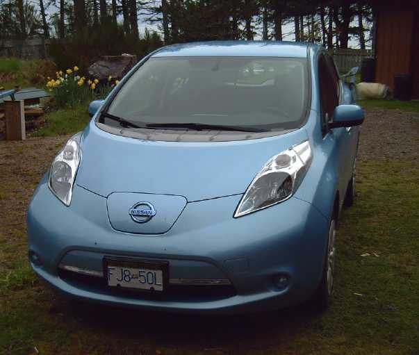 Tom phoned from Victoria
and said gasoline prices in
BC had gone up and are threatening to go substantially further this
summer. I didn't know since I hadn't (& still haven't) bought any
gas myself since early
February. Along with the gas the price of used
Nissan Leafs
has spiked up and dealers' inventories are depleted. And it seems
there's a waiting list for new Leafs. I guess I got mine at a good
time! (Tom himself - after all his months of trying to get one he could
afford - got a sharp looking black 2011 from motorize.ca
[Sidney BC], just in time.)
Tom phoned from Victoria
and said gasoline prices in
BC had gone up and are threatening to go substantially further this
summer. I didn't know since I hadn't (& still haven't) bought any
gas myself since early
February. Along with the gas the price of used
Nissan Leafs
has spiked up and dealers' inventories are depleted. And it seems
there's a waiting list for new Leafs. I guess I got mine at a good
time! (Tom himself - after all his months of trying to get one he could
afford - got a sharp looking black 2011 from motorize.ca
[Sidney BC], just in time.)
It seems good that the astute are starting to heed such
early warnings,
before oil supplies truly get scarce and prices out of reach. People
are waking up, or being
kicked
awake by the cost to fill up their tank. It should boost the whole
field of electric transport. There are new makes and models appearing,
but I expect
that unless manufacturers are really getting serious, there won't be
enough EVs around
to meet demand from now on and for a long time, even while new
petroleum vehicles are being consigned to sit in huge fields, in the
Nevada
desert, and on unused airfields for want of
buyers. (The nickel-nickel batteries would help reduce EV making costs,
if they
were in production.)
At the start of May Ford ceased production of cars, and GM
is cutting production including of the Volt. Perhaps ironically Tesla
cars too is in financial difficulty with production delays, in spite of
having waiting customers. And gas went up again! An article on
Zerohedge.com wondered if rising fuel prices would cost consumers as
much as Trump's tax cuts would save them.
Tom also bought and sent me a second "LELink" Car
Diagnostic
Scanner, a small device that plugs in under the dash and communicates
everything about the car, even the driving and charging history, to
your cell phone via "Bluetooth" with an app
called "Leaf Spy".
The one town on this island I thought I couldn't go to and
return from in the electric Leaf without recharging was Masset - 170 Km
return trip. And
that (mostly that) kept me from canceling the insurance on the Toyota
Echo, tho it's now been over two months since I've been up there. So
I've paid about 140$ insurance for the Echo to sit in the yard. Then I
figured: the faster you drive, the more power you
use per kilometer, and vise versa. Gas cars are most efficient running
at 60-70
KmPH. They use energy just to idle, so it's not helpful to go much
slower. But
with electric cars, the slower you go the more efficient it is down to
some very low speed. I thought that if I drove to and from Masset at 60
KmPH instead of 90, there should be just enough range. The trip would
take an hour and a half each way instead of an hour. That's better than
charging for several hours at 120 volts to get the range back for the
return trip. The idea of simply
driving substantially slower somehow hadn't crossed my mind. (What?
Slower instead of Faster!?!) Where there's more traffic such a plan
might be impractical, but it should work okay here. I tried some
driving at 65 KmPH, and the "kilometers left" goes up after charging
following those trips, eg, suggesting on one day that it could make 180
Km. But another day I drove to Port Clements and back at about 62 KmPH,
at 85 Km round trip exactly half the distance of Masset. When I got
there it looked good, but on the drive home, puzzlingly, the range
dropped much faster than going there, and by the time I got home it
showed considerably less
range remaining than the distance I'd driven. So it looked like I'd
have to
have driven at 50 to 55 KmPH for a Masset trip. That's getting down to
tedious and embarrassing speeds for the highway. If the charge gets too
low
before home, I could - would have to - stop
at Port Clements or somewhere in Tlell for a couple of hour's charge
and a
long coffee to get a few kilometers of boost. If only there was even
one real EV charging station in Masset it would be of great
assistance.
The Leaf is a plush, luxurious car. One would pay a
fortune to get its quiet sound level in a gas car. I've heard frogs
croaking in the ditches as I drive down the highway. Deer grazing right
by the road don't even look up. Two great features (that may sound
trivial or even silly) are the heated seats and the heated
steering wheel. They're especially valuable in an EV where the air
heating system must take its substantial power from the batteries and
hence
reduces driving range. Almost down to freezing, one can get in the car
and almost immediately be warm, without turning on the general heat.
One sometimes needs to turn the heat on for a few moments
to defog the windshield, or if it's really cold. Here the Leaf is still
better
than most, with a more economical heat pump instead of just resistance
heating. This also gives it air conditioning for warm climates or
excessive summer heat.
I'll mention my one dislike: power steering. It's great
for dragging the wheels around in the driveway, but on the highway the
normally minute, virtually unnoticeable steering adjustments that keep
a car nicely on the road take effort: The steering wheel doesn't
budge from wherever it's currently pointed without a certain amount of
force, and every slight adjustment in either direction requires that
force. Normally the steering is often in slight motion without the
driver being aware of it, but with power steering each adjustment is
larger and evident to the driver - "clunky". In my humble opinion.
Other than that, the car has one very serious drawback:
the manual says not to tow a trailer with it. With the propensity of
motor controllers for blowing up if pushed too far, I'm taking that
seriously. But it
means that even if the Leaf will
do for all my other driving, I have to keep the Echo for very
occasional trailer hauling use including for towing the boat. For now,
both trailers' insurance has expired, and I've transferred the Echo's
license and insurance to the Sprint for now for electric driving tests.
I guess it'll stay that way until I need to tow -- or see a need to go
to
Masset rapidly or if I'm not feeling adventurous enough for a really
slow drive. Or
until the Sprint is running on the highway and has great range, if that
ever happens.
The 2018 Nissan Leafs have 40 KWH batteries where the 2015
has just 24 KWH. Such a battery would give it the required range for
the whole island.
Other "Green" Electric Equipment Projects
Carmichael
Mill ("Bandsaw Alaska Mill")
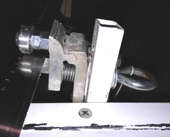 I couldn't let a third
month pass by without at least trying out the band alignment guide
& adjuster I had 3/4 made
in February. I finished it off on the 26th and tried it out.
I couldn't let a third
month pass by without at least trying out the band alignment guide
& adjuster I had 3/4 made
in February. I finished it off on the 26th and tried it out.
Earlier I
had met an retired logger neighbor who asked if I used the alignment
board all
the way down a log, or just for the first cut to flatten the top of the
log. Like most people, just for the top cut. He said that was the
mistake everyone makes. If you throw the board back on top for every
cut, the boards come out smoothest all the way down, without cumulative
errors creeping in.
So I screwed a narrow piece of plywood
on top of the
6"
wide test cut piece. But I should have chosen a fatter piece of wood to
cut
from. And where the saw had slid easily on the spruce cants, it didn't
want to
slide on the plywood. And where most Alaska mills have an end
stop/guide both above the below the blade, I just had one below, which
sucked in under the lower bark on this thin piece. It was kind of hard
to
tell what was
not going well since nothing was.
The adjustment eye bolt wasn't tight and quickly started
adjusting itself, causing the saw to cut downward. I put on a piece of
thin wire to hold its rotation in place and tried again. I forced the
saw along a
ways. Looking at the left edge of the cut it appeared to be going down
a bit, so I tightened the adjuster up a bit - less than 1/8 turn
(shortened the wire a bit). That seemed to work because the cut changed
direction slightly and came back to the right height.
(I took the pictures after backing the saw part way out.
The blade wasn't twisted like that during the cutting! The
left leg however did twist like that while cutting, showing
a weakness in the build.)
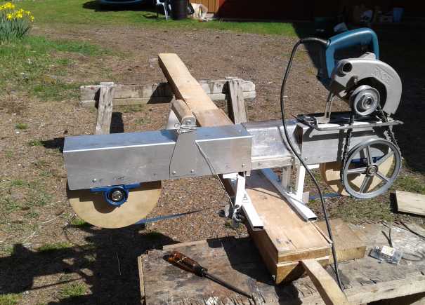 Meanwhile I
hadn't changed the right side guide
yet. It had no adjustment and a
little play in it, so the band aimed itself where it pleased. The
bandsaw videos I'd watched indicated the top (left) side was the more
critical, but the right apparently isn't trivial either and after a
while the
band, while (with the adjustment) straight enough at the left edge, was
down quite a way on the right and I had to stop. I had cut all of 2-1/2
feet.
Meanwhile I
hadn't changed the right side guide
yet. It had no adjustment and a
little play in it, so the band aimed itself where it pleased. The
bandsaw videos I'd watched indicated the top (left) side was the more
critical, but the right apparently isn't trivial either and after a
while the
band, while (with the adjustment) straight enough at the left edge, was
down quite a way on the right and I had to stop. I had cut all of 2-1/2
feet.
As I went, I saw that a couple of other things had come
loose and shifted, and that the saw needed to be beefed up
in 2 or 3 different ways. The "skis" for gliding along the board didn't
work as well as the regular cross-bars Alaska mill layout, so they
should
be changed to that.
At this point I could just
say I had proved the point,
that the Carmichael mill idea works, and hope that I could get funding
to hire others to take the design to the production level. But that
would ignore the original reason for creating the mill: all those
spruce cants and a huge log sitting in my driveway waiting to be cut
into lumber! (And the first of the lumber would go to making a lumber
shed for the rest so it wouldn't all rot!) I'll have to spend some more
time
on it - make the other adjustable guide and work out the bugs.
 On the left side, when the cut started digging
downward, I moved the adjustment a bit and it started correcting, going
up again.
On the left side, when the cut started digging
downward, I moved the adjustment a bit and it started correcting, going
up again.
 On the right side, it started digging down and
the adjustment screw isn't made yet, so it kept getting deeper
On the right side, it started digging down and
the adjustment screw isn't made yet, so it kept getting deeper
after the arrow position and the saw twisted even more to the right.
(It's hard to see as the cut ran into the
bark; also it appears I cut the picture off too short on the right,
before the end of the cut.)
Indoor
Vegetable
Growing With LED Lights (and other gardening)
 Here's the
"regular" mid-month picture of the LED indoor
garden, April 11th. Over half the leaf lettuce had been harvested, and
a couple of the "coastal star" romaine. This is the best romaine I've
ever grown. (I'm glad because I'm sure romaine's nutritional value is
highest. The flavor tends to confirm it, IMHO. But
someone told me a leaf lettuce I gave her was delicious too.) The
potato
that grew itself was towering over everything in both boxes at the back.
Here's the
"regular" mid-month picture of the LED indoor
garden, April 11th. Over half the leaf lettuce had been harvested, and
a couple of the "coastal star" romaine. This is the best romaine I've
ever grown. (I'm glad because I'm sure romaine's nutritional value is
highest. The flavor tends to confirm it, IMHO. But
someone told me a leaf lettuce I gave her was delicious too.) The
potato
that grew itself was towering over everything in both boxes at the back.
The spinach in the third box has been taking its time but
was finally growing. Only two "counter lettuce" (romaine)
came up from a whole row planted in that box. Evidently the
tomatoes in the big pot have been badly underwatered as one has wilted
and its replacement had just keeled over the previous night as well.
(The "popcorn" pot was still empty. Perhaps 3 or 4 peppers would be
good
in it? My peppers in seedling trays hadn't come up. Perhaps I should
complain to the grocery where I bought the yellow pepper? But two came
up later.) I planted
some quinoa just a week before and it shot
up tall and spindly. (Middle-left seedling tray below.) Was it getting
enough light? I planted some more, to go outside in the fenced garden
area. It's a grain and
one thing you
can grow besides potatoes that has some calories in it, plus some
protein. (Wheat and oats take too much room to fence off. I'm sure the
deer would eat all I could plant around here!)
Some seedlings have been transplanted into the greenhouse:
tomatoes, zucchini and cucumber. (Only 2 cucumbers came up. A small
slug ate one, and one of two leaves off the other, in the greenhouse.
One zucchini wilted.) I also planted
peas and beans in the greenhouse. Space for climbing plants like peas
and pole beans would be hard to light up well indoors. Bush beans might
be managed.
I just planted some onion seeds in the clear plastic tray
(edge barely visible, far right, below).
I started so early, in January. How is it I'm now behind schedule on
planting spring seedlings for the greenhouse and the regular garden?
Somehow the 3 large
boxes used up most of the space and what's left for seedling trays is
limited. And some of my seeds are getting rather old, leading to poor
germination rates. By the time you realize some things aren't growing,
it's almost past time to plant replacements.
Here it is on
the 20th. By about the end of the month I was eating lots of spinach,
and I removed and emptied the left box. The leaf lettuce was starting
to get bitter
(meaning it was getting ready to go to seed) and there wasn't much left
anyway.
The "coastal star" romaine,
which has provided some heads and many leaves plucked form the
remaining ones, is getting tough too. But the two "counter lettuce"
romaine in with the spinach are getting larger.
A couple of tomatoes in the black pot and the "popcorn"
bucket are now growing by the day.
A few tomatoes, a couple of peppers, a zuchini and a
cucumber from the seedling pots are now in a greenhouse.
The boxes were planted mid January, mid February and mid
March. I didn't get around to an April box, only to planting some more
seedlings. But it's now getting to be a good time to grow things
outdoors, and I plan to curtail the indoor garden down to maybe some
tomatoes and peppers. Or even put everything outside. It has served its
chief purpose of providing
good, fresh greens in the winter and starting seedlings early indoors.
I'll start it up again perhaps in August when it's too late to plant
more lettuce and spinach outside. I'll bring a tomato plant or two in
when it starts getting cold. And maybe next winter I'll try planting
some dwarf peas and bush beans.
 The
'volunteer' potato had
lots of leaves, but only pretty tiny white potatoes on May 2nd. (2"
long and under) You can grow
potatoes in the summer and keep them over the winter, so I don't think
I'd recommend growing them indoors in most climates, but another month
or two might have given better results. (I think they grow leaves first
and the potatoes later.)
The
'volunteer' potato had
lots of leaves, but only pretty tiny white potatoes on May 2nd. (2"
long and under) You can grow
potatoes in the summer and keep them over the winter, so I don't think
I'd recommend growing them indoors in most climates, but another month
or two might have given better results. (I think they grow leaves first
and the potatoes later.)
Here are a couple of shots of the outdoor garden, with the
south wall painted white to reflect more light. The 54" tall stucco
wire fence (such as it is) beside the sidewalk is to keep the deer out.
That didn't stop at least one as I found hoof prints - but I may have
left the gate by the greenhouse open. Luckily it didn't seem to have
eaten anything. (I saw a deer that day, but it was outside the fence at
the time.)

 Left: The near greenhouse of two. (I think the
"Solexx" plastic blocks too much light and I wouldn't buy it again for
the often cloudy west coast.)
Left: The near greenhouse of two. (I think the
"Solexx" plastic blocks too much light and I wouldn't buy it again for
the often cloudy west coast.)
I planted some Haida potatoes (purple meat and skin) at the far end by
the garage door and an almond tree in the middle. The rest has yet to
be planted. (May 3rd: carrots, spinach) I sprinkled on some wood ash
(ferilizer - esp. potash/potassium) which I'll mix in before planting.
(Okay I'll say it: peeing on unplanted ground adds good nitrogen. It is
in fact rather concentrated and will burn many plants or cause them to
wilt.) The seaweed probably adds phosphorus(?) Crushed seashells add
calcium and the well water here adds lots of iron all by itself.
Right: More potatoes, blueberry bushes and strawberries under the bay
window, and a quinoa patch just planted near the porch. Most of the 5
spindly quinoa plants from the seedling pots just keeled over and
wilted (2 or 3 may grow), so all the rows were seeded directly. So much
for the head start with seedlings! Another almond tree is in a pot by
the porch.
Small
Creek... and larger... Hydro Power Units?
 I mentioned my
vision for a "spiral staircase" "turbine pipe" hydro generator
last month. I intended to but didn't get around to drawing a diagram.
This
didn't
pass unnoticed. Here is a visualization of a propeller driven "turbine
pipe" from the end. One must imagine a long, straight pipe of identical
'windplant' shaped blades rather than a hodgepodge of model airplane
propellers in a bucket.
I mentioned my
vision for a "spiral staircase" "turbine pipe" hydro generator
last month. I intended to but didn't get around to drawing a diagram.
This
didn't
pass unnoticed. Here is a visualization of a propeller driven "turbine
pipe" from the end. One must imagine a long, straight pipe of identical
'windplant' shaped blades rather than a hodgepodge of model airplane
propellers in a bucket.
To get really technical, one should also imagine the shaft
being mounted on bearings with spokes to the outside, a connection to
the generator, and vanes on the inside of the pipe to stop the water
column from starting to spin with the propellers as it goes down the
shaft.
(As a side thought, I wonder if there's an application for
this sort of a pipe and propellers, an "extended ducted fan" in getting
highest thrust per power for a ground effect craft?)
I would use this type of propeller if the pipe was full of
water. If the pipe was to be less than 1/2 full of water, I might
instead try angled paddles of some sort - "canoe paddles" or the
"radiation hazard" symbol sort of triangle shape.
In addition, I thought a bit more about water wheels on
floating platforms. Typically there are 5 or 6 big flat 'plywood'
blades. The turning is bound to be somewhat lumpy, and I thought of a
"venetian blind slat" type of shape in a previous issue. But perhaps a
sideways version of the 'spiral staircase' could come in really handy.
Either narrower paddles could be staggered around the wheel for a more
even turning, or the 'stairs' could be optimally shaped propellers at
steep angles to the flow. The advantages to the propellers are (a) the
wheel could turn faster than the current and (b) the blades could
extract more energy from the water with less drag. Interestingly, since
they are turning at right angles, along the flow instead of across it,
they would be shaped like airplane propellers and not mirror image like
windplant propellers. Since they would cause considerable sideways
thrust, they would be in pairs pushing oppositely. This might be
something simple to try on the smallest scale with model airplane
propellers... and I even had a few of those!
Thinking of that is when I put together the shaft with my
6 props on it, and took them down to a creek.
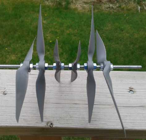
 1/4" threaded shaft with 6 propellers (60
degree intervals).
1/4" threaded shaft with 6 propellers (60
degree intervals).
In order that it not push sideways, the propellers would be in pairs.
Here in the middle are two 7" props.
One is a "pusher", the other a "puller", meant to turn in opposite
directions on model aircraft.
Outside of that are two 8" props, again a puller and a pusher, but with
different pitches.
The two largest are a 9" and a 10" puller, on the right in the stream
but on opposite ends in the other picture.
(When they hit the water, the pull to the side was noticeable.)
Of course it turned. How could it not? Of course more propellers,
matched and closer together with smaller angles between 'stairs', would
provide more and more even thrust from the same flow. It might be worth
getting a bunch of matching puller/pusher propellers and a small
generator to try actually making power, however little.
The real key is of course that one needs flowing water
that one is in a position to make use of with permission to do so, and
the desire and means to make power from it. If there's lots of flowing
water compared to the amount of power desired, then exactly how the
flow is turned into rotary motion, whether it is done more or less
efficiently, isn't critical. To make the most of a limited supply,
turbine efficiency becomes a considerable factor.
The
Electromagnetic Spectrum, John Bedini & HE Ray Energy
 I found and went over a section describing the electromagnetic spectrum
in The
Urantia Book (Paper 42:5 which I missed before, also 58:3). It
seems there are considered to be 100 octaves in the spectrum, of which
visible light is said to be octave number 46, with the "short space
rays" 32 octaves above that, making them octave 78. That leaves us with
the problem that most tables are done in powers of ten rather than
octaves. Initially confusing, but the math is actually pretty trivial
(with a calculator): 2 ^ 32 = ~4.295*10^9 -- a little over 4
billion.
I found and went over a section describing the electromagnetic spectrum
in The
Urantia Book (Paper 42:5 which I missed before, also 58:3). It
seems there are considered to be 100 octaves in the spectrum, of which
visible light is said to be octave number 46, with the "short space
rays" 32 octaves above that, making them octave 78. That leaves us with
the problem that most tables are done in powers of ten rather than
octaves. Initially confusing, but the math is actually pretty trivial
(with a calculator): 2 ^ 32 = ~4.295*10^9 -- a little over 4
billion.
A photon at a wavelength of 500 nanometers, around the
midpoint of the visible light octave, has about 2.5 electron volts. So
a photon 32 octaves up has around 10 billion electron volts (2.5*4
billion), in the "giga electron volt" (GeV) range. Gamma rays are
typically considered to be in the mega (MeV) energy range. GeV would be
the range known to astronomers as "HE" rays in the region of 10^24
Hz rather than "VHE" (high energy / very high energy), which would
appear then to center on octave 88 at around 10^27 Hz. That
would probably make the 10 terravolt (TeV) "VHE rays" to be
"Higgs-Bossunic"/"adamic"/"ultamatonic" energy at the edge of known
quantum physics.
But it is the "short space rays" - "HE" rays, probably
spanning several octaves - that seem to be where the concentrated ("400
times as much") energy lies. And the "gamma ray observatory" satellites
certainly seemed to be seeing far more GeV rays than TeV. I think it's
this region of the spectrum which surprised astronomers and of which
they said "If you had gamma ray eyes, no part
of the sky would be dark." I was confused by the astronomers calling
them all "gamma rays" ("gamma rays" (MeV), "HE gamma rays" (GeV) and
"VHE gamma rays" (TeV))
regardless of the million to one spread in wavelength, frequency and
photon energy over these diverse bands. (So I suppose technically I had
it wrong
again or at least a distorted impression in my previous writings. What
else is new?)
Full 100 octave
electromagnetic spectrum
(Expanded from Wikipedia chart per UB 42:5)
This is all somewhat academic, I suppose. The relevant
thing here is that some sort of high energy rays exist ("beyond gamma
rays" as Moray put it) and rain down on the Earth (coming
preferentially from the plane of the Milky Way) and that there are
known (even if not well or commonly known and understood) ways to
extract their high energy, "a sudden change in electronic pressure"
(ie, via large voltage spikes) being the relevant one.
While trying to make the Curtis "Sep Ex" motor controller
run the series wound forklift motor, I started thinking of various
things, and these led me to John Bedini's motors and later to the above
reading.
In my once again aborted project to make "VHE ray" energy
last summer, I had noticed that the MOSFET coil driver circuit was done
wrong. Mark had said he had had a very hard time when he switched from
tubes to solid state and it appeared that no one after him had been
successful with his design. I began to suspect the design was
needlessly
complicated, and also that Mark's need for the "kick of the kick of the
kick" to get things going along with the difficulty in controlling the
units was really the fault of the faulty driver circuit (probably along
with stray voltage spike currents activating MOSFET gates at the wrong
times). Another thing that seems odd in retrospect is that the output
transformer coils were connected to the driving coils as well as the
"collector coil" in "autotransformer" fashion, confusing everything.
Assuming the ray energy is delivered as a surcharge in the magnetic
field, Bedini's circuit with an isolated output coil should be much
easier to
work with.
Like Tesla and Moray, Mark got started using tubes. The
high voltage switching needed to get the energy conversions happening
probably explains the reason people in "early days" got energy: tubes
need those sorts of voltages to work anyway. Once low voltage
transistor circuits started becoming the norm, nobody works with high
enough voltages to see anomalous results any more. Except maybe in
working with motors. They have coils that generate a high voltage spike
when they're turned off suddenly as they are with electronic controls.
Meanwhile Bedini had confounded people by having a
motor both doing mechanical work and charging a battery at the same
time, with a pretty simple circuit, that didn't seem to draw enough
from the powering battery to
account for it all. Originally he thought he was recovering waste
energy from the motor with his second coil, but that energy is
recovered in any good motor and controller anyway. So I think that once
he
understood that, like Mark, he didn't seem to understand where the
power was coming from himself. Evidently he said that it came "from the
environment". Technically this would be true but it's hardly an
explanation. I ran across this diagram of one of his motors in The
Free Energy Handbook:
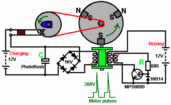
It was the "200 volt motor pulses" spikes shown under the
motor that
caught my attention rather than anything else. That would probably be a
high enough voltage spike
to cause HE rays to release their energy into the electromagnetic
field, adding their energy to it. There was the extra
energy to charge the second battery from. If Bedini's motor worked as
everyone seemed to have found that it did, and assuming that that was
what
was happening, it meant that capturing (V)HE ray energy must be simpler
than I
had come to believe. Which is only likely considering all the people
who have done it or who have been rumored to have done it without
knowing what they were doing since Tesla over 100 years ago.
One problem with replicating the devices of most
of these inventors are that they used custom components whose
construction and use are poorly described. And with coils, the (poorly
described) spatial relationship and orientation are key. Bedini's
designs are the
most straightforward and well documented, but one must build a motor.
But central to his
motors is an extra coil. One can make 200 volt spikes in a coil where
nothing moves as easily as in a motor, and magnetically couple that to
another
coil to isolate it electrically, as he did. That would eliminate the
motor. How about a high current double
coil 570 uH toroidal double inductor such as the ones I got from
mouser.com for
my unpolar motor controller? Also central to his designs is a switch
that only draws power from the output coil a low percentage of the
time, to "pulse charge" the battery. The rest of the time, the coil is
unloaded and free to accumulate the requisite voltages to harness the
rays to make it work.
As we see, the right hand side of the diagram is the power
input. Instead of the motor with a 'sensor' coil to turn the power on,
we could use a simple PWM circuit such as the common one using a 555
timer chip with a few components (some earlier
TE News), driving the power transistor. (This
might be used with feedback from the output side: if the voltage across
"C" is
too high, reduce the PWM width or the frequency, and vise versa if it's
too low.) And I would think that the 80 volt, 1/2 amp MPS8099 should be
replaced by a transistor of much higher ratings. To get much power out,
some amps do have to go in.
And shouldn't the transistor need to be rated 200+ volts
if
there are 200 volts spikes in the coil at turn-off time? Again one
suspects that Bedini, like Mark, wasn't a trained electronic circuit
designer who knew what he was doing. But that may have turned out well,
because
if he was he'd have put in the usual transient suppression diode to
shunt the 200 volt turn-off spike, and there'd be no HE ray
energy capture.
The left hand side of the circuit is the electrical power
output side (electrically isolated from the rest). The rectifier can be
a typical four terminal diode bridge
rectifier such as one I have, GBPC3508. (35 amps, 800 volts. GBPC3510
is 1000 volts.) I presume the so called
"photoflash" is simply a capacitor, probably rated 400 volts or better
for a good safety margin. (Unless it arcs across to discharge very high
voltages for safety?) So the output side develops a high voltage
which is then discharged through the rotary switch. In a similar Bedini
circuit drawing he uses a huge capacitor, something like "342,000
microfarads". That could handle a pretty heavy load for a while once
the voltage has built up.
The rotary switch can be replaced with an IGBT or MOSFET
switch, probably NPN or N channel in the minus leg. My idea ideally
would be to
run 240 volt loads (or even better 120 volts if that's high enough)
that could run on DC current such as electric
resistance heaters (with no fan), so as not to drop the voltage down
when the switch is on.
The switch would be on as long as the voltage was considered sufficient
- 230 or 200 (or 100?) volts. If the voltage is too high, the input
side needs to
cut back the power pulses. If it gets too low and the input is at max,
it needs to switch the load on and off, or the ray capture will quit.
If it can run a heater continuously... Perfect!
For driving the motor field coils, the Curtis 1243
controller has a 36 volt drive instead of 12 volts, so it should put
out a good pulse. Some lab work with a voltmeter and an oscilloscope
was
doubtless in order here. (4 solid days of cutting, cleaning and hauling
spruce branches isn't very conducive to energy project work!) On the
29th I hooked things up. In the first test I just used the inductor.
Then I hooked the motor field in series in case that would do something
magical. The results were pretty predictable in both cases: the motor
controller had diodes and probably active rectification to dampen down
voltage spikes, and there were no high voltages anywhere to be seen
with the oscilloscope. The meter showed the DC output with no load got
up to 37 VDC.
There was still one way to get higher voltage pulses. The
inductor's coils only had 5 winds each, of heavy wire. 50 windings on
the output side should make 20 volts into 200. But I tried 20 winds and
the inductance was 7.4 millihenries. That was already over 12 times
higher inductance. I used #14 wire. The voltage ran up to over 100
volts - 120 if
I stepped on the gas pedal. Was that enough voltage? When I dug out and
connected a 40 watt
incandescent light bulb, turning it on killed it - 0 volts. It wasn't
even getting good transformer action between the two coils. That was
enough for one day!
It did seem all too simple! What happened to that one or
two turns 'collector coil' everybody had at 90 degrees to everything
else? That would put it where the transformer iron/ferrite is. Nobody
connects anything to the transformer iron!
(What was the physical orientation of Bedini's coils in
his motors? That's where schematic circuit diagrams with mechanical
components fall down. They show coils, but not necessarily their true
position or orientation.)
Could I just wind a wire, a "collector loop", around the
whole outside of the inductor? Would 100+ volts induced into the
secondary cause anything to happen in that? What should the secondary -
and the collector loop - connect to? Or was the collector loop just a
closed hoop like Mark seemed to have it? Maybe I should at least go
over my own notes from past tries!
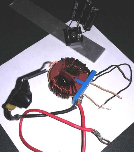 I
found some heavy flat "ribbon" wire with pretty heavy
insulation for magnet wire (a "gritty" texture). On the 30th I drilled
two more holes in the plastic base. I managed to slide the ribbon wire
under the original coil, but my 20 turn coil was wound tighter
(somewhat thinner wire, #14) and it wouldn't go in. I unwound it and
put the other half of the collector loop in, then wound it up again.
(This time, knowing a single layer wouldn't fit on the inside, I
doubled things up such that voltages that were far apart (120 volts,
remember) weren't on windings that touched each other.) I now had a
wire running around the toroid just outside where the iron (or ferrite
or whatever) is. Hah, I now seemed to have a "toroidal" unit
configuration after all! The simplest possible version with one pulsed
coil, one collector loop, and one output coil. Now the problem is, what
connects to what? and why? In any sort of system, everything has to
work together or it won't work. Birds have wings, but they can't fly
without a tail. In this sort of system, if anything isn't right, it
won't work... and will one be able to figure out what's wrong when
nothing happens? In spite of thinking the principles must be pretty
simple, my level of confidence at actually being able to get it going
isn't really that high. Maybe the voltage was too low?
I
found some heavy flat "ribbon" wire with pretty heavy
insulation for magnet wire (a "gritty" texture). On the 30th I drilled
two more holes in the plastic base. I managed to slide the ribbon wire
under the original coil, but my 20 turn coil was wound tighter
(somewhat thinner wire, #14) and it wouldn't go in. I unwound it and
put the other half of the collector loop in, then wound it up again.
(This time, knowing a single layer wouldn't fit on the inside, I
doubled things up such that voltages that were far apart (120 volts,
remember) weren't on windings that touched each other.) I now had a
wire running around the toroid just outside where the iron (or ferrite
or whatever) is. Hah, I now seemed to have a "toroidal" unit
configuration after all! The simplest possible version with one pulsed
coil, one collector loop, and one output coil. Now the problem is, what
connects to what? and why? In any sort of system, everything has to
work together or it won't work. Birds have wings, but they can't fly
without a tail. In this sort of system, if anything isn't right, it
won't work... and will one be able to figure out what's wrong when
nothing happens? In spite of thinking the principles must be pretty
simple, my level of confidence at actually being able to get it going
isn't really that high. Maybe the voltage was too low?
Coil unit April 30th. Left,
wires to motor controller field drive
with original double 5 winds coil (570 uH). Right side, voltage
raising 20 winds coil (7400 uH). Under the other coils, the
"collector loop" at 90°, a single turn of flat "ribbon" magnet
wire (light brown). To the right the diode bridge (on an
aluminum "heat sink" piece) and capacitors: 3 * 270 uF, 100 V
in series making it 90 uF, 300 volts.
Nothing ventured nothing gained, on May 1st I put it out
on the lawn beside the car and hooked it up.
I soldered the two ends of the "collector loop" together
and put the diodes and capacitors back on the "output" coil. Again the
DC output voltage rose in some seconds to around 120. But when the lamp
was switched on, the voltage dropped to 2.5 volts instead of 0.0. I
connected the "loop" to the output coil. When connected to one end of
the coil, the voltage dropped back to zero when the lamp was switched
on. On the other end, it dropped to 2.5 again.
Then I recalled that some people had used permanent
magnets in their circuits. I brought out a supermagnet. It surprised
me: it had wildly different effects depending on its placement and
orientation. In the first places I tried beside the toroid, it
prevented the voltage from rising even with the lamp turned off. In
some placements it was wouldn't even hit 10 volts. Then I put it on the
outside and the voltage rose as usual to over 100. But when the lamp
was switched on it dropped to 8 volts instead of 2.5. Sideways on the
outside it managed to retain 11 volts. (Could I have seen the filament
glow if it was dark out?) But there was nothing anywhere to suggest
that there was any power coming in except that supplied by the car
batteries via the motor controller pulses. If I connected the lamp
directly to the motor controller, the meter read 37 volts DC, the
programmer said "no current" and the filament glowed dimly.
I didn't quite ignore safety. The unit wasn't in a metal
box, but I was sitting a few feet away to turn the car key on. I made
sure to turn off the controller, turn on the lamp and watch the 100+
output volts drop to zero before going to the unit and doing anything.
That includes moving the magnet. It might be more interesting and
perhaps instructive to be moving the magnet around and watch the
effects on the meter. But in case something works, I don't want those
severe RF burns that others have had by having their hands too close.
The HE rays are there - here, there and everywhere. But I'm missing
something.
Nickel-Nickel
with Oxalate Battery Chemie
How good would it be?
Despite best intentions I was unable to find any time to
work on batteries. Having the washing machine in pieces on the floor of
my "lab"
also made for no room to work. (The repair part that was supposed to
arrive "in 3 or 4 days" took that many weeks to reach me on Haida
Gwaii.)
But I wondered how nickel-nickel would rate compared to
lithiums.
Counting just the nickel, theoretically a nickel negative has about 477
AH/Kg (2 electrons are moved per reaction), and the positive 289 (one
electron moves).
The nickel discharges to nickel hydroxide in both electrodes. ...or
will
it be nickel oxalate? Two OH- weighs 34. One C2O2-- weighs 56. Add the
nickel, 59, and the total is 93 or 115 (grams/mole). Perhaps some of
each? Call it an average of 100. We then get 281 AH/Kg for the negative
and
141 for the positive. So needing 2 Kg of "+" for each Kg of "-", we get
281 for 3 Kg or 94 AH/Kg. If we consider the voltage under load to be
1.2, that's 113 WH/Kg. So with packaging et al it won't be any higher
than
the lithiums - the ones in the Sprint car worked out to 91 WH/Kg. Maybe
on a par. But there are a lot of factors that could
come into play. How much extra hydrogen might the metallic nickel
store? What improvement might nickel manganate or (?)lanthanum
nickelate(?) make in the positive? And on the other hand how much is
the performance reduced by the
weight of the copper alloy plate, or by the added copper in solid
solution with the
nickel in the "+" side?
Obviously there are still a lot of unknowns, some pluses
and some minuses. The big advantages would be lower cost and in theory
indefinite cycle life. Indefinite cycle life is a huge advantage. It
provides confidence to say a vehicle has "X" driving range and will
continue to have "X" driving range without issues or expenses for as
long as it is on the road.
http://www.TurquoiseEnergy.com
Haida Gwaii, BC Canada