Turquoise Energy Ltd. News #120
covering May
2018 (Posted June 4th)
Lawnhill BC Canada
by Craig Carmichael
www.TurquoiseEnergy.com
= www.ElectricCaik.com
= www.ElectricHubcap.com
= www.ElectricWeel.com
Feature: Nickel-Nickel Battery: Should
be better,
cheaper than Lithiums. Next step, developmental production.
(See Month in Brief,
Electricity Storage)
Month
In Brief
(Project Summaries etc.)
In Passing
(Miscellaneous topics, editorial comments & opinionated rants)
- Project Reports
-
Electric
Transport - Electric Hubcap Motor Systems
* Chevy Sprint Car, continued
* Reluctance Motor Designing Idea: Make it Flexible!
Other "Green"
Electric Equipment Projects
* Carmichael Mill ("Handheld Bandsaw Alaska Mill")
- potential competition? Nope! - Various constructions and
trials - Cutting (a few) real boards - Superior band guides
* Proposed New Electrical Standards "RFC": a new standard Voltage,
and
Standard Connectors for 12 VDC, 38 VDC
- New "38 volt DC" (+/- 15% = 33 to 43.7 volts) proposed as a
"standard wiring voltage"
- midway between 12 volt and 120 volt (3 times 12
volts; 1/3 of 120 volts)
- 1/3 the current and wire size of 12 V
- much lower line losses than 12 V, good for
moderate power appliances as well as low power
- highest 'safe to touch' line voltage
- Revised CAT standard 12 volt plugs and receptacles (a little
smaller, better connections and grip)
- New HAT standard 38 volt plugs and receptacles (size is close
to original CAT std., longer and stiffer prongs/blades)
* "The Indoor Vegetable Garden" - Year round gardening with LED
Lights! (and other gardening) (Last update for the season?)
Electricity Generation
* HE Ray Energy - notes on magnetic saturation & grounding
Electricity Storage -
Turquoise Battery Project (NiMn, NiNi, O2-Ni), etc.
* Nickel-Nickel Batteries - Further cell experiments - Cell
construction and test - Water electrolyte cell - More tests
-
High Resistance Electrode can be solved by VERY VERY powerful
compaction - NiNi
Must Next Move to Developmental Production
- Negative Current Collector Metal as a
metal hydride for double energy storage?
May in Brief
 More gratuitous beach pictures having nothing
to do with the newsletter
More gratuitous beach pictures having nothing
to do with the newsletter
Here's all we can see of the BC mainland from Lawnhill - very
occasionally when it's really clear all the way across:
a few
mountain peaks somewhere in the direction of Prince Rupert.
(They seemed clearer to my eyes than they do in the picture.
Some around the right hand arrow had glaciers but most of the white at
the horizon is just clouds.)
Someone says they're not the coast range, but taller peaks farther
inland.
Someone else says only atmospheric refraction would allow them to be
seen around the curve of the Earth from this distance.
(It might be interesting to check out the trigonometry on those!)
 Just a day or two after I posted the last
newsletter saying how the beach was
Just a day or two after I posted the last
newsletter saying how the beach was
usually mostly covered with a film of water and reflective, it was
mostly dry, perhaps
as the snow had mostly melted in the mountains and the weather improved.
(I also started to realize that it's about the only beach with sand
along this coast.
Most of them are just rocky. I got lucky when I bought this place!)

I started the month working a bit more on the Electric
Chevy Sprint car, which
was getting to run pretty well but not very fast. (20-25 KmPH - but it
looks like you could drive it for about 4 hours on a charge!) I started
thinking more seriously about making a new reluctance motor. Back EMF
is so low, and the rotor just a solid piece of steel (or steel
laminate), that it can be spun up to very high RPMs, and the power just
goes up with speed. 10,000 RPM would have the Sprint doing 100 KmPH.
And if the "permanent magnet assisted" motor idea works as well as it
seems to, the car would also have amazing range for its batteries.
 Then I got
back to the bandsaw. It wasn't co-operating and
I turned the wheels around so the front was the back & v.v., which
moved them forward 3/4" and made more space for the band guides, lack
of which had been the cause of some troubles. Now all had to be
remounted
and repositioned. It was still unsatisfactory. Later I decided to cut
thin
slots in UHMW PE plastic and mount them as band guides. They worked
well at first but
wore out quickly. It was worth a try! Then I saw a Woodmizer band mill
and how they had
done "railway car" band guide wheels. I'll try a variation on that
next. I welded and turned a pair of these guide wheels with rims on the
back to keep the band from pushing backward. That will eliminate the
two troublesome rear wheels. But I only got one mounted by month's end.
Then I got
back to the bandsaw. It wasn't co-operating and
I turned the wheels around so the front was the back & v.v., which
moved them forward 3/4" and made more space for the band guides, lack
of which had been the cause of some troubles. Now all had to be
remounted
and repositioned. It was still unsatisfactory. Later I decided to cut
thin
slots in UHMW PE plastic and mount them as band guides. They worked
well at first but
wore out quickly. It was worth a try! Then I saw a Woodmizer band mill
and how they had
done "railway car" band guide wheels. I'll try a variation on that
next. I welded and turned a pair of these guide wheels with rims on the
back to keep the band from pushing backward. That will eliminate the
two troublesome rear wheels. But I only got one mounted by month's end.
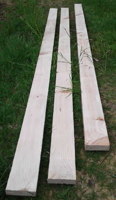
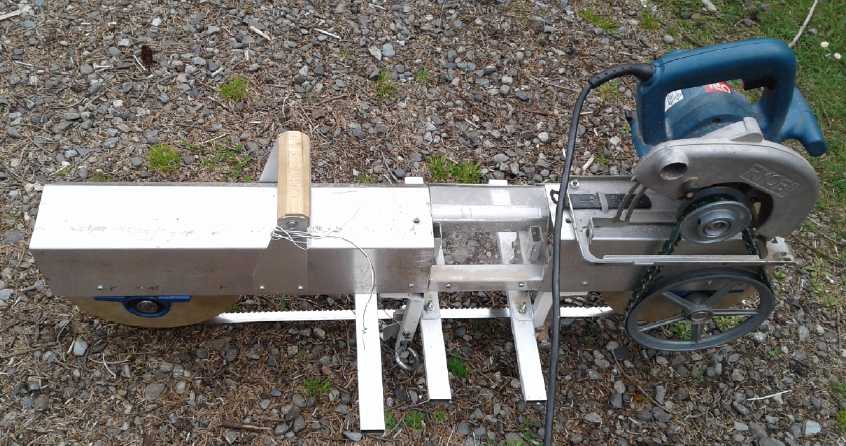
 13' Boards cut using the UHMW band guides; New
"Railway Car" band guide wheels.
13' Boards cut using the UHMW band guides; New
"Railway Car" band guide wheels.
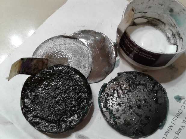
Nickel-Nickel Batteries
Along with the bandmill, from mid month I experimented
with new NiNi battery
cells and electrodes, and then that became the main focus. Much was
learned. The reason I've usually had low
capacities is that the substances have been poorly compacted and so the
electronic conductivity has been such that most of the substance isn't
being used. The extreme pressures required for compacting can doubtless
be had much the same way Edison got them: making very small cross
section electrodes and feeding in a bit of material at a time from the
end, then pressing it ...or walloping it with a sledgehammer or maul.
But others have made various nickel hydroxide electrodes since since
Edison and there are probably more elegant solutions. If graphite
powder could be used as a conductivity additive it wouldn't need such
extreme compaction pressure, but graphite causes strong self-discharge
with this chemistry.
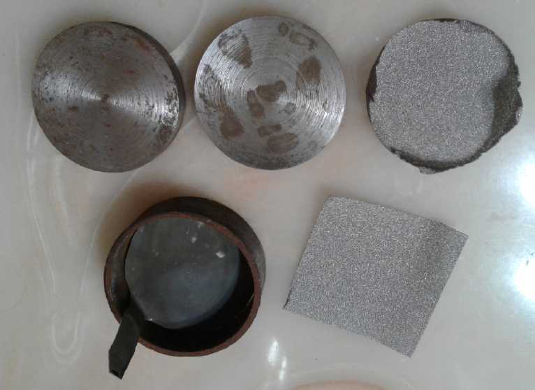
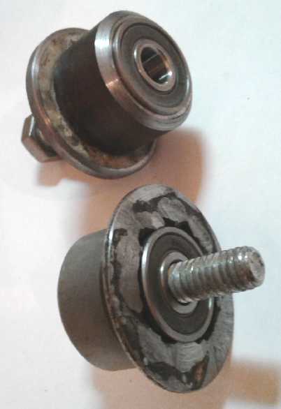
- Plastic pill bottle
bottom as housing
- etched cupro-nickel sheet with tab terminal as minus current
collector
- compacted nickel powder and nickel mesh minus
electrode
- separator paper with "mud" electrode on it (extra paper bit to shield
tab)
- coated graphite sheet as plus current collector (connection to top
surface)
- (All wet with electrolyte, wax seal broken around graphite for
disassembly)
 On the 15th I decided to try doing an
improved test cell. Using the nickel mesh and nickel
flake powder, then compacting them in the press at 10 Mg (megagrams or
metric tons), seemed
to make very nice negative electrodes. The other electrode wouldn't
hold together at all. It stayed as powder until wetted, and then it
became mud. Current capacity was pathetic. But chemically it worked!
And with the oxalate being a great chelating
agent as well as the electrolyte, there would seem to be no chemical
reason it wouldn't last forever - unlimited charge-discharge cycles.
What are the unique features?
On the 15th I decided to try doing an
improved test cell. Using the nickel mesh and nickel
flake powder, then compacting them in the press at 10 Mg (megagrams or
metric tons), seemed
to make very nice negative electrodes. The other electrode wouldn't
hold together at all. It stayed as powder until wetted, and then it
became mud. Current capacity was pathetic. But chemically it worked!
And with the oxalate being a great chelating
agent as well as the electrolyte, there would seem to be no chemical
reason it wouldn't last forever - unlimited charge-discharge cycles.
What are the unique features?
* More mildly alkaline electrolyte (pH 12-13) using potassium oxalate
and calcium
hydroxide instead of potassium hydroxide. Besides hydroxide, oxalate
is an ion that nickel and many metals are insoluble in. Finding some
such salt with this rare property was a key.
* The electrolyte is dissolved in ethaline DES [Deep Eutectic Solvent]
instead of water.
Ethaline has high overvoltages before it starts breaking down. (DESes
do
however have lower current capacity - slower ion flow than water. The
chemistry might or might not be coaxed to
work in water, which has a lower oxygen breakdown voltage.)
* The more mildly alkaline electrolyte permits nickel to be used
as a
negative electrode. Nickel has more available amp-hours per kilogram
(as opposed to theoretical values) than any other metal and is highly
conductive.
* The positive electrode - what I'm using in the present tests - is a
unique formulation of
oxidized monel powder (nickel:copper alloy), nickel hydroxide,
lanthanum hydroxide, and thiamin (from canned beans). The monel with
the copper makes the electrode more conductive. Other formulations
better than plain nickel hydroxide are certainly possible and are used
by others, notably
nickel with manganese, which forms mixed nickel manganates, of lower
resistance and taking on various
oxidation states in charge and discharge.
* For the positive electrode current collector, a thin conductive film
of acetal ester doped with osmium (powder) coats a graphite current
collector
sheet. This prevents contact between the graphite and the electrolyte.
In a less alkaline solution, the reaction voltage of the positive
electrode is higher, and graphite will react to cause oxygen separation
and self discharge. Every metal will also corrode away to oxide. This
problem, solved by the osmium doped film, is what has kept this sort of
battery chemistry from being created previously.
---
Wow did it ever take me a ridiculously long time to figure all that
out and put everything together at the same time into one cell! I had
most of it by 2011 or 2012. Except for the ethaline DES
[Thanks Leonardo Janus for bringing that to my attention!] - and
thinking graphite simply couldn't be the big self-discharge problem - I
might have
had good cells several years ago, and I should have tried out the DES
about two years ago. Going from my early and original oxalic acid idea
to
potassium oxalate was a pretty big leap too, but became a relatively
obvious thing to do once I finally started experimenting with it. I
presume that my
2.6 volt nickel-manganese cells should work great with similar
formulations and electrolyte, too!)
An important aspect of production will be compaction of
the positive electrode powder. It seems it requires 16-20 tons per
square centimeter - and that may be less than optimum. Other battery
makers have solved this same problem in various ways. It would seem one
way to get such pressures, needed only for an instant, is to drop heavy
weights on a small area electrode compactor die rather than to try to
use a press, which would need to be enormously heavy. I used a 6 pound
maul to bash it with. It wasn't enough and I need to pound on a smaller
surface area. (I may have a solution but we're into June and I have to
end this newsletter.)
But it does seem like this battery is ready to move at
least to some sort of early production level. Then real uniform,
manufactured cells can be tested and proportions, mixtures, techniques
and construction can be tweaked up to maximum performance.
Another interesting prospect is that typical metal
hydrides are
composed largely of nickel. Once all the nickel has charged back to
metal
chemically, if the alloy is specially formulated, it is possible that
the
nickel electrode could also become a metal hydride at just .1 volts
more
negative charge than the nickel redox reaction, and thus hold a whole
further charge of hydrogen ions
(protons) giving it double capacity at almost the same voltage. As the
battery was used, first the hydride would discharge,
then the nickel would oxidize. Whether a practical high capacity
hydride can be formed on top of having the nickel chemical reactions
however is a speculative idea, not a
proven concept. It can be tried out once sealed cells are being
produced - it can't be tried in unsealed test cells.
Nissan Leaf versus GM EV1 - another invidious(?) comparison
A month or two ago I had wondered why the Nissan Leaf
seemed to use substantially more energy per kilometer than was reported
as being used by the GM EV1 two decades ago. The EV1 got more driving
range
from fairly similar battery energy - 160 miles (250 Km) versus 160
kilometers. Certainly for highway driving wind resistance is a factor,
and the EV1 had the lowest wind drag of any production car
ever, while one can feel it's fairly substantial in the Leaf at higher
speeds
and a headwind definitely seems to cause it to use more electricity per
kilometer. (it doesn't get blown around by crosswinds the way the
Toyota Echo does, though.)
Somehow it had never occurred to me to wonder what they
weighed. While the weight of the Leaf wasn't given in the manual, there
was a "GVWR" label on the door panel. Subtracting "860 pounds maximum
passengers + cargo" from the sticker's 4193 pounds makes the curb
weight 3333 pounds. The EV1 was 2850 pounds, so 500 pounds less in
spite of its somewhat heavier nickel-metal hydride batteries. So rear
seats (the EV1 only had two
seats), larger space overall and plushness come with a price. It's in
electricity and range. If used Leafs
weren't 1/2 the price of any other readily available production
electric car, speaking only for myself I'd rather be able to travel to
anywhere on this island
and home again. Sometimes the extra space is useful; again just for me,
rarely the extra seats. But if I still lived in Victoria where
distances are smaller, the Leaf would be perfect except for rare longer
highway trips.
The Sprint's 1800 pounds or so (though with less than 1/2
the
battery capacity) certainly makes it a flyweight. But the Sprint with
the small forklift motor and fixed 8.9:1 reduction doesn't go fast
enough for
the street much less the highway. I took one more leisurely drive up
Lawnhill Road in it at 20 KmPH (where I found and examined the
Woodmizer band mill), and then transferred the insurance back
to the Toyota Echo and insured my trailer as well, so that I could both
reach Masset and carry plywood (etc) when I want to.
Before I could use the Echo, however, I had to fix the
sticking brake piston on the front right wheel. After I did that I took
it for a test drive and discovered the the front left was also
sticking. All that sand and salt on the highway last winter was
certainly hard on the car! I spent the 27th fixing that, and since
I just couldn't leave it with 3 wheels done, I replaced the brake shoes
on the fourth, the rear right,
as well, rather prematurely. (The front
brake pads had lots left. Just those costly cylinders had to be
replaced - about 260$ just for the parts to fix them myself!)
On June 1st I drove the Echo up to Masset. En route I
visited some people who milled lumber and who were very interested in
the mill. They had read about the idea in my December article in the
Haida Gwaii Trader magazine. Their blade mill had a 3/8" kerf so they
were turning a lot of wood into sawdust to cut boards. So! Even people
who already have sawmills are potential customers for the handheld band
mill! (But they were out of the cheap salvaged 3/4" plywood I was
looking for. Rats!)
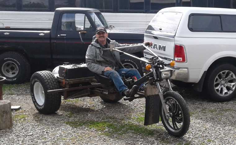 In Masset I
met up with Lawrence of Driftech Mechanical who had built an electric
tricycle I had heard of earlier. He was closing up shop for the day and
we went to his house and he showed me the tricycle and demoed it. It
was a far more impressive machine than I had expected from the name
"tricycle", one that could
burn rubber and was well capable of fantastic acceleration to highway
speeds and beyond. It would 'blow away' gas cars. It had a Volkswagen
manual transmission and a 48 volt forklift motor (longer than mine in
the Sprint and probably 80 pounds instead of 50), being run at 72 volts
with 6 lead-acid batteries that gave it about a 20 Km range.
In Masset I
met up with Lawrence of Driftech Mechanical who had built an electric
tricycle I had heard of earlier. He was closing up shop for the day and
we went to his house and he showed me the tricycle and demoed it. It
was a far more impressive machine than I had expected from the name
"tricycle", one that could
burn rubber and was well capable of fantastic acceleration to highway
speeds and beyond. It would 'blow away' gas cars. It had a Volkswagen
manual transmission and a 48 volt forklift motor (longer than mine in
the Sprint and probably 80 pounds instead of 50), being run at 72 volts
with 6 lead-acid batteries that gave it about a 20 Km range.
He reached the far end of the block in a flash and was turning around
before I could even walk a few yards to the road to get a picture, and
I didn't get a good one. (A
video would be better. I didn't even think of that!)
In getting ready to finish this newsletter I copied the
month's pictures onto a USB memory stick. All seemed in order. Just as
I was about to delete them off the phone (AKA the camera), my brother
phoned my cell phone number, by accident. He said his phone was in his
pocket until he heard me say "Hello". I lost the USB connection to the
computer when I answered so I didn't delete the photos. This proved to
be fortunate as they hadn't transferred properly. Over half the
pictures either weren't there or had internal errors in their data and
were missing major sections. There were no indications anything was
wrong until I tried to view them. Our guardian angels work in creative
ways!
I copied them again from the phone onto another USB memory
stick... with pretty much the same results. For whatever reason, I had
to copy a few at a time instead of all at once.
In Passing
(Miscellaneous topics, editorial comments & opinionated rants)
Fish Freezing Tip
 Fish meat in
the freezer gets "freezer burned" quickly. It's
been said that one shouldn't try to keep frozen fish longer than about
3
months. But when I was a teenager our family froze a whole fish in an
ice cream pail full of water. About a year later we dug it out and ate
it. It was still perfectly good and fresh tasting.
Fish meat in
the freezer gets "freezer burned" quickly. It's
been said that one shouldn't try to keep frozen fish longer than about
3
months. But when I was a teenager our family froze a whole fish in an
ice cream pail full of water. About a year later we dug it out and ate
it. It was still perfectly good and fresh tasting.
Here is some halibut I was given. I cut it into steaks
and
separated them with some plastic bags so I can (hopefully) separate
them out of the container of water (ice) when I want to eat one. I
confess it might be hard to get them
apart. But they'll last a long time in the freezer!
---
You know you're out in the boonies when you go into a cafe called
"Angela's", and it's not a chain; it's owned and run by a woman named
"Angela".
Emergency Instructions:
Yellow alert: Get the heck out! Step on it!
Red alert: Stop and wait for it to turn
green
again.
"in depth reports" for
each project are below. I hope they may be useful to anyone who wants
to get
into a similar project, to glean ideas for how something
might be done, as well as things that might have been tried or thought
of... and even of how not to do something - why it didn't
work or proved impractical. Sometimes they set out inventive thoughts
almost as they occur - and are the actual organization and elaboration
in
writing of
those thoughts. They are thus partly a diary and are not
extensively proof-read for literary perfection and consistency before
publication. I hope they add to the body of wisdom for other
researchers and developers to help them find more productive paths and
avoid potential pitfalls.
Chevy Sprint
Car - Forklift Motor & Fixed (8.9:1) Reduction
Misc. Improvements
On the 5th I put the rear view mirror back on. The tow
truck driver had sheared it off on a tree when he pulled it out of my
yard when I was moving. I glued the 3 plastic screw sockets back on
with methylene chloride, reinforcing each one with an extra piece of
ABS plastic, also stuck on with methylene chloride. (It was lucky the
mirror's plastic was amenable to softening/melting with methylene
chloride.) Then I tapped the metal on the door, bent or ripped by the
screws, back to its original shape and screwed the mirror back on.
As the car seemed to be running well I got up the nerve to
use the programmer to raise the
motor current limit to 250 amps instead of 200. I drove across the
acreage once, and then went on the highway to the acreage next door. It
was a considerable difference. It got up to over 25 KmPH instead of 20.
This time it sounded like the motor was winding up some and it should
have been about 2500 RPM. I drove through the two-driveway yard to
turn around. But on the way back it didn't go much over 20 because the
slope was a bit up instead of down. From that speed it went up my
driveway hill with seemingly good margin, unlike the first trip when it
barely made it back up. It's still nothing like the speed and power one
wants on the street, let alone on the highway. So far it's a relief
just to go out and get back without getting stuck out on the road
somewhere. Should I try the full 300 amps? Hmm!
I neglected to bring a current clamp meter for the battery
current and I didn't check the motor current. (Not a very methodical
experimenter, am I? But then, one can't be looking down at meters much
while driving. I totaled my very nice white Tercel wagon (bought new in
1986) in 1993 and suffered substantial injuries by looking down for a
moment too long at the wrong time. PS: Seatbelts save lives!)
But the next day, the 6th, I upped the motor current limit
to the full 300 amps and tried the same paths (twice to get more meter
readings), reading the battery current clamp-on meter. It still didn't
get up to 30 on the highway - somewhere over 25, and a little faster
but still under 25 on the way back. Really no better than when limited
to 250 amps. (If it was running well, the Electric Hubcap motor
would have at least got it up to 30!) Battery currents were up to
130 to 180 amps in acceleration or uphill, with just one reading
somewhere well over 200. But on the highway at "top" speeds they were
down to about 53 amps going (=2.7 HP, down slope) and 83 amps on the
way back (=4.2 HP, up slope). That meant that the motor simply didn't
want to rev up any higher with a 36 volt supply. (At least then there
was no worry
then about it over-revving and flying apart!)
With 3 sets of cells in parallel, the Sprint would be
easier on the batteries than the Swift was. 180 amps (6840 watts @ 38
volts, 9.1 HP) even if it was continuous is only 60 amps from each
battery cell, where the Swift could easily draw 120 amps continuous
from its one set.
For the same 10000 watts (100 amps @ 100 volts) that the Swift used to
drive along the highway, the Sprint would only draw 265 amps (265 amps
@ 38 volts), or 85 amps per cell instead of 100. But I think that the
Sprint would use less power with the less lossy transmission... if it
could attain highway speeds. (Sorry about the confusingly similar car
names, "Swift" and "Sprint". I didn't name them.)
If one took the median power, about 70 amps, what might
the range be? To leave a very minimum reserve one might use 250
amp-hours out of the 300 available. (supposedly available - these
aren't new batteries) 250/70=3.57 hours of driving. At 25 KmPH, that
would be about 90 Km, using just over 100 WH/Km. That's not very
impressive given the low speed. A better motor would seem to be in
order.
If I had used the 4 to 1 transmission reduction I first
thought about instead of the 8.9 to 1, top speed would have been about
55 to 60 - but only if it would start moving, which it might not if
facing uphill, starting from a pothole, on soggy lawn, etc. To go
faster with this motor and controller the car would need that variable
transmission or multiple gears to keep the motor speed down at higher
travel speeds... or a higher motor voltage.
Going uphill on a last leisurely drive up Lawnhill road
before transferring the license and insurance back to the Echo seemed
to show it probably wouldn't maintain highway speeds going up grades,
regardless of gearing, with the 36 volt supply.
There are several problems with higher voltage. First the
motor controller is 36 volts. I'd have to buy another one for 48 volts.
Second, that would still only take it up to 35 KmPH - nothing like
highway speeds. Third, would it be over-revving? Probably it
would be fine at 48 volts/35 KmPH, but it was after all supposed to be
a 36 volt motor, and I hadn't done it any favors busting the fan rim
trying to take it apart. On top of those things, fitting the extra
batteries would be a nuisance, fitting four solar panels would be even
harder, and I had just bought the 36 volt to 120 VAC inverter to run
from the car in case
of power failures. Plus I'd rather stay at 36-40 volts than up it to
48-54. 72 volts would take it to 50 KmPH, but that's getting quite
dangerous and the motor really might break up at 5000 RPM. I had
grounded the system to the car frame, assuming the highest voltage
wouldn't be hazardous.
I'm pleased that it runs and seems reliable, but when I
couldn't get it going any faster, I rather lost enthusiasm for the
project as presently configured. As from the very start, it needs a
variable transmission or a faster motor. (I also wanted to get the
bandsaw mill working.)
Reluctance Motor: What's Available?
I thought that perhaps there might be a higher RPM
forklift or other suitable sep-ex motor available. But even if it was
rated 6000 RPM - a very high RPM for a larger size motor - that
wouldn't be highway speeds. 10000 RPM continuous would be a good rating
to shoot for. But at that speed there would be 16 times as much
centrifugal force on the rotor as at 2500 RPM.
It all makes me think more about reluctance motors with
their very low back EMF and solid steel (or steel
laminates) rotor, that can do such high RPMs safely and efficiently.
(And surely it would be even better if it was PM assisted.) Since power
is torque times speed and the torque is still high at high RPMs, quite
a small motor should have the power for a car if it can be cooled
adequately. The rotor makes no heat, so only the stator coils need
cooling. An adequately cooled reluctance motor should give the desired
9200 RPM for 100 KmPH. If a motor was also permanent magnet assisted
the currents should be substantially reduced, reducing the current and
heating loads, and hence the motor size - or at least the cooling
requirements - could be further reduced.
Then again, it's been 3 years since I was doing the
reluctance motors. Has someone else invented this particular wheel
since I had been working on it? Times do change. Time for a web search!
A web search on the 7th came up mostly with studies and
theory about reluctance motors. There were a couple of line voltage
reluctance motors available, 1800 and 3300 watts at 120 and 240 volts.
They came with their own motor controllers. They only went to lower
RPMs - in the
3000s range. There was nothing that looked applicable to power
transport. And I saw nothing about PM assisted reluctance motors. The
field would appear to be still wide open.
Once again, with development funds much could be done
probably resulting in a commercial transport motor and controller
relatively quickly. With one person part time one might be getting good
results just as commercial products started to emerge elsewhere. It
doesn't matter much at that point whether yours is better or not; the
main market is passing by.
DC to DC Converter Idea Again
Setting the HE rays idea aside, I started thinking that if
the dual inductor (or other such device) could be used as an effective
pulse
transformer, it could go the other way: the 20 turn coil could be the
input and the 5 turn coil the output. That should reduce the voltage to
1/4 and multiply the current by 4 times. That would have the same
effect as putting 4 times as many winds in the motor coils, without
changing the motor. 15 amps from the controller's field drive would
become 60 amps into the motor field - enough to at least get the car to
move. Of course, that would be if it worked as an effective transformer
with high currents. I wasn't seeing that when going the other way, from
the 5 to the 20 turn coils. The 120 volts DC output built up only
gradually, and it died the instant the light bulb was turned on.
That doesn't necessarily mean the idea wouldn't work with
the right transformer. And diodes that would take the current - perhaps
low voltage alternator diodes.
Reluctance
Motor Designing Idea?: Make it Flexible!
In my 2015 reluctance motor
experiments I cut or had cut rotor shapes to suit my ideas at the time.
Now I think, why not just use a relatively thin solid rotor disk like
the ones from Princess Auto ("7.8 inch Brake Disk with 1 inch shaft")
and bolt pieces of steel to it to try out various shapes and sizes of
"salient poles"? They would just have to have bolt holes to line up
with the bolt holes in the disk. That should make it easier to try
different things out to discover the most optimum patterns.
Other "Green" Electric Equipment Projects
Carmichael
Mill ("Bandsaw Alaska Mill")
Handheld Bandsaw: potential
competition? Nope!
I checked out "handheld bandsaw", which device someone had
mentioned. Had I reinvented a wheel that was already being made and
sold commercially?
But they proved to be an entirely different thing from a
lumber mill. The band twisted around 90° so it cut downward instead
of horizontally with the same saw orientation. They could only cut
less than 5" wide by 5" deep before the work would hit the frame. A
demo I saw showed one cutting only unspecified metal bars and tubes,
not wood. (If the pieces were steel, it was far more impressive than if
they were aluminum. What a crappy video not to say, when they were
blabbing throughout, jokes and trivia!) If it was used for cutting
wood, it couldn't do much more than crosscut 4"x4"s to length. But they
cut freehand, so one would surely get straighter cuts from a skillsaw.
The blade bands were only about 35" in length and they said theirs was
17 pounds.
It could be a very nice metalworking tool to have -
potentially better cuts than an angle grinder with a zip disk, without
the expense and bulk of a typical metal bandsaw. But it was nothing
like the "Carmichael Mill" in construction, purpose or potential use.
Band Guide
I got back to the mill on the evening of the 8th and got
part of the other adjustable band guide done. I noticed that one "ski"
had been crooked all along because a hole wasn't in quite the right
place. I filed it out a bit so the left assembly could be straight. I
finished it on the 9th.
Trials
Then I tried out the saw but adjustments were "out of
whack". The bearing holders being bolted into slots they can be moved
as desired, but of course each thing that can be moved becomes an
adjustment point that has to be carefully aligned. A production saw
would eliminate most of the adjustments with fixed position parts, cut
and drilled exactly by CNC so everything would fit perfectly without
adjustments. Only the vital adjustments - the band guides, band tension
(allowing band replacement) and perhaps one wheel tilt - would be
adjustable. As I was trying to adjust things while attempting to cut a
piece of wood, it started to rain. That ended that!
I returned to the chase the next day (10th). When
everything seemed to be in order I set a fatter beam on the sawhorses
and brought out the saw. I had already tried cutting this beam from
both ends with the cuts going off, so the saw would have to make its
own new path without simply trying to follow another. In adjusting I
found
that the band in the wood could be seen to have veered down or up by
looking at
the band guide on each side. I had just a little trouble with the right
side but plenty with the left. The spring didn't seem to be strong
enough to force the guides to move to cut more downward. I soon went to
the spring drawer and found one that I could cut a suitable piece off
of. It fit just inside the other and I worked them both into position
and got the the adjustment bolt back through inside them.
The direction of adjustment seemed counterintuitive and
had to be thought about. The pivot hinge was behind the bearings, so if
the blade went down below, lowering the aim brought the guides closer
to the cut. But lowering the aim meant the cut would veer downward
even faster. It had to be aimed up so further cutting would bring the
band back up to where the guide wheels were. And then, which way did
one turn the bolt to achieve that? I'm sure I got it wrong more than
once, and I had to back up and cut another slot that went the right
way. Since the adjustments weren't very close to start with, it took a
while and a few tries to get it going well. I stopped and checked every
few inches or a foot.
It was easy to tell when it was running well: the motor
and band turned more freely, and the saw bounded ahead into the wood.
When it was going off, it got harder and harder to cut, and the band
would get hot. (Sometimes, if the band didn't have enough tension, it
would cut a catenary, the shape of a wire between two telephone poles,
instead of a flat board. This time I seemed to have it tense enough to
avoid that... for 6" wide. What about 16"? Well, everything in its own
time!) At one point, the band came off the wheels. I thought I'd have
to stop there because that's hard enough to adjust even in the shop on
the bench. But I persevered, tightening and loosening pillow block
bearing bolts and pushing the bearing blocks around with a screwdriver,
until finally the band stayed on when the saw was running. Eventually,
adjusting the guides quite a lot for a while but gradually getting them
better aligned as I went along the board, I came to the far end. I had
cut a real 12.5' spruce board, 1.5" x 6", usable for coarse purposes or
if planed down thinner until it was flat. Now, if only the next one
would go much faster!
The top of the beam was too hilly to use as a flat surface
for the next cut. I looked around for a 1" x 6" to put on top but I
didn't see anything suitable. So that was enough for the day! After I
put everything away I looked for sawdust. If I had used a chainsaw mill
I could have raked up a small mound of chips, I'm sure. But there was
just a bit of fine dust in the gravel. I didn't even see it at first.
On the 11th I got it out again and cut a couple more
boards. I was starting to get it better adjusted and by the second one
it cut more or less straight rather than digging down or rising up. But
there was still a bit of catenary and it still went up and down a bit
here and there. These might be improved by more blade tension. And even
when cutting well the band was still getting hot. I could have cut much
faster if I hadn't kept stopping to let it cool. (Once the temper is
gone from the teeth, any blade is toast.) Pushing the bearing blocks
with a screwdriver seemed like a poor way to try to tension it both
because it was hard to get good tension and because it had to be done
on both sides of a wheel, making it hard to keep the wheel aligned.
Now What?
The next items to tackle for improvement were:
* Get the right rear band guide back on (it didn't seem to fit right
with the new adjustable top-bottom wheels)
* water drip to cool the blade
* some sort of screw system to tension and align one of the wheels.
* Front and back board glides instead of the left and right skis.
Imperfect Wheels
I thought about how to do band tensioners on the 13th.
Suddenly it occurred to me to try something. Sure enough, when I turned
the wheels to different points of rotation, the band got looser and
tighter. For all my efforts, the plywood wheels weren't entirely even
and concentric all the way around. That doubtless explained some of the
unpredictability of results. It would to be hard to fix with confidence
without making new wheels, preferably of cast aluminum alloy, turned to
machine precision.
I thought again of the wheels on the meat cutting bandsaw.
They were very different from other bandsaw wheels. A rim at the back
stopped the bands from going too far back, and the relatively flat
outer rim was just slightly too narrow: the tips of the teeth were
always just off the front, touching nothing. I thought this
design might well be the best. If they had been 10" instead of 8" I
think
I'd have pulled them out and tried to use them in the mill. They were
cast from
steel rather than aluminum. I wondered if I could make anything like
that? Given my lack of success at casting an aluminum boat propeller
blade a few years ago, I decided that casting them was out. And then,
as is so often the case, they couldn't quite have fit onto my
lathe to machine down.
What about just trimming the present wheels nearer to
perfection? Perhaps right on the saw, with a file or some sort of
scraper? For the powered one, just remove the band and turn on the
motor? The other one might be trickier. I took off the band. (I managed
to run my hand into the blade a couple of times and cut a knuckle a bit
- what else is new?) I stuck a chisel next to the rims and turned,
shaving off bits of wood. It
seemed to be mostly just the driving wheel was a little off center. In
other words, the center of the wheel on the saw was somehow slightly
different than it had been on the lathe when I made it. It was off
enough to explain it all. I had sharpened along one edge of this chisel
as well as the tip, and I used this edge to scrape the high area down
as I turned, while resting the sharp end of the chisel on the saw body
as a lever
so it wasn't "freehand". At first I turned the pulley by hand, but that
was too tedious and I used the motor.
Again, I started thinking that with a bigger lathe I could
have completely assembled the wheels on their axles and turned them
true, hopefully preventing this later misalignment. I've started to
realize that many things I've done - or wanted to do but couldn't -
would have been simplified or made possible if I had a bigger diameter
lathe. So many rotors and things have been 10". The lathe has a 10.0"
gap, which is at best minutely too small to turn any item down to 10".
And it's hard to get a 10" piece mounted and on even if it doesn't hit
the frame. If it was 11" instead of 10 and the 'gap' area of that
diameter was about 3" longer, it would make a tremendous difference.
It's such a small amount - maybe I should take the angle grinder to the
body of my lathe and trim it down a bit!
When I was 'done' I wasn't happy with the alignment - the
band was riding too far forward on the wheels. But I took it out and
tried to cut into a new cant. I got a few feet in before it went out of
line. There still didn't seem to be much tension, either, and I
suspected that was another reason it wouldn't stay in line. Back in the
shop the tension still seemed to depend on the position - ugh! Well,
maybe I'll try making the tensioners and it can be sufficiently tense
everywhere? And maybe I'll take the wheels apart and see if there's any
way to make sure they run more centered.
Band Tensioners and Aligners:
Loosen the bearings a bit and screw both end bolts to press against
them.
Then tighten the bearings up again.
 On the 14th I
made the tensioners. I had been
wondering
how, but on this morning I simply walked up to a pail of scrap aluminum
and
picked up a 1/2" thick by 1" wide bar. (Gosh, I had a piece that
thick?) I cut off two pieces 2.5" long. I drilled and tapped one end,
off center (5/16" - 3/16" in 1/2" thick), for a 1/4" adjustment bolt.
Then I drilled two holes for 5/16" carriage bolts to mount the pieces
on the saw "backbone". The pieces were mounted solidly in place with
the head of the 1/4" bolt on the end touching the bearing holders for
the undriven wheel. With the bolts on the bearing holders loosened,
unscrewing the bolt pushed the bearing holders along the carriage. This
arrangement was able to put considerable pressure on the bearings and
wheel, which could be aligned so the band ran as desired and tightened
to provide substantial band tension.
On the 14th I
made the tensioners. I had been
wondering
how, but on this morning I simply walked up to a pail of scrap aluminum
and
picked up a 1/2" thick by 1" wide bar. (Gosh, I had a piece that
thick?) I cut off two pieces 2.5" long. I drilled and tapped one end,
off center (5/16" - 3/16" in 1/2" thick), for a 1/4" adjustment bolt.
Then I drilled two holes for 5/16" carriage bolts to mount the pieces
on the saw "backbone". The pieces were mounted solidly in place with
the head of the 1/4" bolt on the end touching the bearing holders for
the undriven wheel. With the bolts on the bearing holders loosened,
unscrewing the bolt pushed the bearing holders along the carriage. This
arrangement was able to put considerable pressure on the bearings and
wheel, which could be aligned so the band ran as desired and tightened
to provide substantial band tension.
 One of the (now two) adjustable band guides
 The adjustable band
guides stuck out farther than
the
originals, and that was part of the trouble getting things into proper
alignment. I had had to leave off one of the bearings that stopped the
band from pushing backward because there just wasn't room to put it on.
Now I realized that if I turned the wheels around, the way they were
mounted on the shafts, they - and the band - would sit about 3/4"
farther toward the front of the saw. That would leave more room to
properly position the band guides. So I realigned the band to run in
the new position and (after much adjusting, with better tension) it
seemed much better.
The adjustable band
guides stuck out farther than
the
originals, and that was part of the trouble getting things into proper
alignment. I had had to leave off one of the bearings that stopped the
band from pushing backward because there just wasn't room to put it on.
Now I realized that if I turned the wheels around, the way they were
mounted on the shafts, they - and the band - would sit about 3/4"
farther toward the front of the saw. That would leave more room to
properly position the band guides. So I realigned the band to run in
the new position and (after much adjusting, with better tension) it
seemed much better.
Then all the band guides needed moving and adjusting. The
rear stop bearings needed to be mounted more solidly as the one still
there had been bending out of place. The mounts needed modified shapes
for the new band position, and to be made from thicker aluminum. I did
that on the 18th and tried it out. It just wouldn't cut straight. I
couldn't make one decent cut in the cant. No adjustments seemed to
help. I took it back in the shop and did some more adjusting and
setting up, but that was all the time I had. Surely the blade couldn't
be dull after cutting only a few boards. Had it hit some rock in this
last piece of wood? Again, if that was common, the whole idea started
to seem a little impractical. I was starting to get pretty discouraged.
The next morning (19th) I decided to give it one more try,
and then try a new cutting band/blade. It occurred to me that it had
come off a rear wheel more than once, and that the two rollers would
have pinched the teeth and reduced or taken out the set - the way teeth
stick out to each side a bit so the cut is wider than the blade behind.
That might explain the poor cutting. But then I noticed that the "skeg"
or "side ski" that the saw buts up against as the blade pulls it
sideways had a mark on it. The blade had also more than once come off
the rollers, and it had hit the skeg. A steel blade cutting steel?:
that all by itself explained why the blade was dull and the saw
wouldn't cut properly! So I put on a new blade. And I took off a bit of
the skeg with the angle grinder so it wasn't so close to the blade, and
cut at a bit of an angle so hopefully (no guarantees) if it did hit it
again, the back of the band would hit instead of the teeth. These of
course are things one learns making a prototype that is actually used,
so they will be built into the production model to eliminate potential
trouble points before there there are hundreds or thousands of the
mills in use.
I tried it again and went about 8 feet though the 12 foot
cant. It seemed to be going nicely. I was using about a 9 foot 2"x6" as
a flat top board and I had to stop and move it to the far end. After
that the saw wanted to bind up for no apparent reason. But I got there
and when it came out the far end the band sprang forward and came off
the wheels. I could see that it had more and more of a "cup" in the
board toward the end after a big knot or after moving the 2"x6", both
at the 8 foot mark. I decided that next time I would cut something down
so I was milling 6 or 8 feet - I just might make a few decent boards
instead of one cut that never finished well. Aside from the mill
itself, the wood had some ugly dark spalting in it and I really had to
start getting it cut up - better I had already done it! Valuable lumber
is going to waste.
(20th) I tried cutting again but one could see by looking
in the end of the cut that within inches it was starting to bow and it
just got worse. The best reasons I could think of for the were (a) that
one side of the band had been dulled and (b) that if the band was
pressed hard against the back guide bearings on each side, it could bow
a bit in the middle and then it would naturally cut up or down in the
middle even while it was cutting straight at the edges; hence the
"cupped" shape. From experience so far, if it's cutting well it isn't
pressed against the back bearings. The thing that presses the band
against the back bearings is if it's not cutting well. If that's
happening right from the start of the cut, it probably means it's dull.
Which meant I had one new band left to try out and see if
I could get good results. But first, I really wanted to change the
"skis" to front and rear cross-slides like chainsaw mills use. The
"skis" weren't keeping it very steady. I also moved the left side out a
couple of inches to 8" width first so I could use a 2"x8" for a top
board and second so I could see if the cut a couple of inches away from
the guides was straight rather than rising or lowering.
Some thoughts: The
more I fiddle with adjustments
on this, the more I think I like the meat cutting saw's exact shaped,
"no drifting backward or forward" rimmed wheels. Surely setting up the
guides and everything should be much simplified. (Of course... I
haven't tried milling wood with it. Maybe I should.)
On the topic, when ripping wood with a regular bandsaw,
when the cut starts to go off a bit, one simply moves the front of the
board left or right, thus re-aiming the angle of the wood going into
the blade. Simple! But that's for thinner boards and it isn't an option
with any band mill. There the band has to cut perfectly in line with
the direction the saw is moving, so the alignment is much more
exacting. And being above a wide horizontal cut, one readily can't see
if the direction is going off soon enough to make such tiny corrections
anyway.
People around here say that band mills are always finicky
and that those who "get serious" about milling lumber soon ditch them
and get a dimensional (2 circular blade) mill. Those "serious" people
aren't the target market here. Like the Alaska mill I think this could
be a fabulous product for milling "in situ" and not having to move big
logs, and to provide a really economical way to make smaller amounts of
lumber from a tree or a few small or special trees. If I can perfect it
to that point...
Then I found that even a family with a dimensional mill
was interested in my mill because it wasted so much less wood than
their thick kerf blades.
It's all in the Band Guides! UHMW Plastic Band Guide Blocks
I thought about it overnight and by morning (21st) I had a
new idea: ditch the complexity of the rolling guide bearings and their
mounts, and make band guide slots in solid blocks of slippery UHMW
polyethylene plastic. With the cooling water system (until then just
stopping often), they should stay cool enough. The sides probably
wouldn't
wear out in any hurry. If the back of the band dug through the plastic
until the teeth hit the guides, they would simply cut the edges of the
plastic slot and not be dulled. In fact, I could extend the fronts of
the guides to the point where the band couldn't come out of the slots
until it also fell off the wheels. That would keep it from hitting the
metal skeg or anything. But if the back of the band did tend to dig in
and wear out the plastic, I could put in a metal pin. If it was
slightly loose, it might even spin in the slippery plastic. Or it could
be shaped specifically to do so with a narrow "axle" at each end. The
back guides would be in line with the side guides - much better - and
the band couldn't go over the edge of the rear guides and slide back
(and be forced crooked), the way it sometimes did with the rear
bearings.
Instead of hinge pin plates for adjustment, I would simply
make the back a shallow arc or a very broad triangle. To aim the band
up, loosen the lower mounting bolt and tighten the upper one to shift
the angle, and vise versa. (No springs to compress themselves and throw
off the aim!)
I made these guides that morning from 1/2" thick UHMW.
They certainly simplified the saw. I looked at the "skis" and how to
change them, and one more time said Ugh! and left them. I set the
guides 8" apart instead of 6" and used a 2"x8" as the guide board. I
had bucked my 12' cant at the 5'/7' mark where a big knot was. It
would probably break there anyway. (It did - it just fell apart.) I
started at the short end. The 5' cut went great - smooth and easy, the
saw gliding through. So I decided to cut the rest. I started having
adjustment problems, mild at first but they didn't seem to correct by
adjusting. When I was 3/4 done, I noticed that the saw band was
overlapping the back of the wheels, almost ready to come off. It had
started about in the middle and the slots as cut wouldn't let it go
back farther. Not surprisingly the back of the band had gradually
deepened the slots. The teeth wouldn't be damaged, but the slots were
widened out by the teeth and once the band was back in the middle they
weren't guiding it much. So it definitely needed some metal at the
back, and now new slots. I finished the cut. The last half of the board
was cupped but not as badly as some.
Another item that's been bothering me, maybe related to
the cupping, is that with the hinge behind the guides, when one adjusts
the guides they not only change angle, their position moves up or down.
That automatically takes them even further out of alignment with
wherever the band is positioned in the wood. I now occurs to me that if
the hinge pin is above (or below) the front of the guide slot instead
of well behind it, the slot will move back and forth a bit, but it will
stay at its same level. I bet that would be a great advantage and
reduce the 'cupping'. And now that my guide is plastic, I can easily
drill a hole and put a hinge pin through it. (As for a piece to hold
that hinge pin and a screw to do the adjusting... hmm!)
But then again, probably the best thing to reduce the
cupping is more band tension. I'm not sure how far to go on that with
my bolted-on plywood wheels, but I expect higher tension is the main
remedy.
On the 24th I just rigged up the same UHMW band guides to
work again. On one I put in a 1/2" spacer to get the thin part of the
slot to the blade; on the other I turned it upside down and cut a new
slot. On both I drilled and tapped holes and put in 1/4" bolts as
"pins" at the rear to stop the back of the band from digging into the
plastic and lengthening the slots. After a bit of cutting I put a
couple of drops of oil on the band where it went into the pins, seeing
how it was metal rubbing on metal.
 UHMW Slot Band Guides on Right and Left side of
the saw.
UHMW Slot Band Guides on Right and Left side of
the saw.
Cutting was quite straight once aligned, until the band wore the slots
wider.
After mashing a finger trying to
reposition it (now a
partly black nail to match the other hand), I cut into the same
heavy cant I was cutting before. For a couple of feet things went well,
but then it started veering up. This time I was listening for the motor
to sound more labored and it didn't get far. I adjusted it down, backed
up 6", and tried again. It cut a new slot and again went well for a
couple more feet. I adjusted it down again and this time it continued
to cut pretty well. By the end of the 13' board it was bowed up just a
bit, but it wasn't a bad board. A couple of times the motor sounded
more labored but I couldn't see anything wrong. It turned out to be
big, hard knots in the wood.
I went to cut another one but the band fell off the front
of the wheels before it started cutting. On examination, damp sawdust
had built up on the plywood wheels where the teeth were, and that made
the wheels wider there. If it's not cutting, the band centers on the
widest point on the wheels, so it moved forward. Another lesson
learned: for a production model the wheels had to have slots in them
for the sawdust to fall out - either radial or axial. or something...
or maybe the usual urethane 'tire' on the bandsaw wheels would shed
sawdust. (even damp sawdust?) One
would think the thin guide slot would scrape it off the band before it
reached the wheel, and it probably did get some of it. For the
prototype with plywood wheels it seemed I would simply have to scrape
the sawdust off the wheels after each board.
I put the band back on and cut another board. This one
went pretty well with only one small adjustment, still on the leading
side and still in the same direction, more downward. There were shallow
dips or bulges where hard knots were, but much less cupping and
otherwise not bad boards.
I cut a third board with no further adjusting except the
height to
make it thicker. But on the
fourth board, the cut didn't start well. On examination, the band guide
slots had worn somewhat wider and weren't guiding the band very well.
It was to be expected I suppose, but if they had lasted even a day's
cutting that might have been good enough. The saw cut the best while
they
lasted - the best results so far. It was worth the try.
Simplifying the Cooling Water Plan
Something I noticed when it was cutting well was that the
band didn't get very hot. Instead of having a continuous flow of water
squirting on it, I started thinking more in terms of just having a wet
sponge contacting the smooth part of the band at the top of its travel.
That would probably keep it pretty much cold. It might be a large
sponge, or a small reservoir on top of a small sponge feeding water to
it, with maybe a funnel to fill it. That simplifies the construction
and the operation (no valve to keep turning turn on and off!) and the
amount of water needed for that won't add any weight to speak of to the
saw.
Operation would probably consist of making sure the reservoir wasn't
empty.
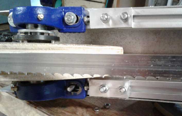
Woodmizer Mill Type Band Guides
My previous rollers in line above and below didn't seem
very good because they sometimes pinched the blade, if adjusted too
tightly or if a bit of sawdust went through. Then it didn't move
freely. But if not quite tight
together, the band could aim itself up or down quite notably - partly
because the wheels weren't very wide. At one point I had to mount two
rollers offset a bit because the holes weren't quite right. Rollers
above and below that
weren't quite in line seemed better. They could even bend the band a
bit and it would only hold it straighter. But it still was a less than
perfect grip. The bearings were still narrow.
Backing up a day, on the 23rd I had driven the Sprint up
Lawnhill road and
there I chanced to see near the road, and of course examined, a
"Woodmizer" bandsaw mill. The band was heavy
and wide, much thicker than any of mine. The band guides were each a
metal(?) block below and a wheel above. The wheels could be adjusted
for gap to the blocks (blade thickness), or the entire assembly could
be pivoted with adjustments at the back. The 2"(?) diameter wheels were
the width of the blade minus the teeth and had "rail car" wheel rims on
the back to stop the band from going backward. That way it didn't need
other wheels farther from the wood as back stops. That would be better,
and also similar to but better than the meat cutting bandsaw with rear
rims on the
main wheels, since the guide wheels are closer to the cutting.
So... How about that design? Rollers the full width of the
band behind the teeth with projecting rims as the "backstop" made a lot
of sense. It's probably the best way to do it. I still thought
slick UHMW bottom blocks on springs would be the way to go for the
blocks.
(But maybe the other way up, with the wheels on the bottom and sprung
blocks on top.) Used that way the plastic pieces could do a lot of
cutting before being worn out, and the guides would present little
friction to motion. And there wouldn't be any manual adjustment for
blade thickness.
 Two bearings
with a washer between them was the width of
the blade less the teeth. A large washer behind that followed by a
third bearing might
make the "rail car" protruding rim. But it turned out there was a
problem. If the inside of the large washer was the diameter of the axle
(a 5/16" bolt) it wouldn't turn with the bearings. If it had a larger
center so it contacted the outer turning parts instead, the nut against
the
unsupported centers of the bearings caused them to jam. I didn't fancy
trying to get two spacers of such exact thickness that they would work,
even if that was possible.
Two bearings
with a washer between them was the width of
the blade less the teeth. A large washer behind that followed by a
third bearing might
make the "rail car" protruding rim. But it turned out there was a
problem. If the inside of the large washer was the diameter of the axle
(a 5/16" bolt) it wouldn't turn with the bearings. If it had a larger
center so it contacted the outer turning parts instead, the nut against
the
unsupported centers of the bearings caused them to jam. I didn't fancy
trying to get two spacers of such exact thickness that they would work,
even if that was possible.
It appeared it
would be necessary to turn a housing with a
rim to fit over two bearings as the shaped wheel, rather than using the
'naked' bearings as a wheel. I tackled these on the 26th - an afternoon
and part of an evening of buying a pipe 'coupler' fitting that looked
like it was
the right size, then cutting it in half, turning off the hex grip part
and welding washers onto one side, then more machining on the lathe to
fit in the bearings et al. On one side of each wheel the bearing can
easily
be popped out. On the other it's a pressed-in fit. I was pretty pleased
with the result.
Perhaps ironically they have the same problem as using
3 bearings and a washer: if a bolt is tightened to hold the wheel, the
bearing centers get pressed together. But here I put very small and
short pieces
of pipe between the two bearings on both wheels so the centers are held
at the right
distance - actually just a little long for a tiny bit of free end play.
Then what about the other
face of the band? My first
thoughts were the plastic on springs, but the bearings offset a
little from those of the first side had worked out well earlier and
started to seem like a very attractive way to do it. The 'rail car'
wheels would of course be innermost, closest to the wood being cut. The
offset bearings/wheels a little farther away on the other side would
simply press the band tight against the inner wheels. They didn't even
have to be very wide, although 'width of the band' like the inner ones
would probably be best. One of them could in fact be used to adjust
band tension - without affecting band alignment like the double
tensioners pressing against the bearing mounts, mentioned above. And if
the tension was was set with a spring it could
compensate and keep the band tension relatively stable even if the
wheels were lumpy such as if sawdust got under the band at the wheels
or whatever.
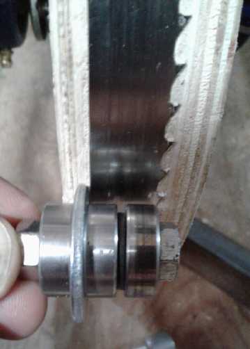
I got just one wheel mounted on the saw on the 29th. It
seemed good. I asked a mechanically inclined neighbor with a sawmill
come over and look at the mill. He seemed to like the offset guide
wheels idea.
He also thought the band was moving too fast and that I
should slow it down. I suspect he's right. It seems ironic that I can't
get a motor that turns fast enough for the car project, and I can't get
one that turns a slower speed for the mill. I can see if any place in
town
has a 10" lightweight aluminum pulley. That would slow it down 20% over
the 8" pulley. Meanwhile I adjusted the pulley on the
Ryobi skill saw out a turn for probably a similar speed reduction.
Proposed New
Electrical Standards: A Low Voltage Standard and Standard Connectors
Okay, I don't make the
rules, but I am going to offer suggestions... How it would be if I was
"in charge" and in the absence of others' thoughts on the subject. I am
open to other ideas as well (particularly extensions to the ideas), so
perhaps this writing is also an RFC (Request For Comments).
Adoption of the proposed standards would not take anything
away from anything or anyone compared to what exists now. It would only
provide focal points for manufacturers to better support those using
low voltage DC line power covered by the specs for whatever purposes -
off-grid, marine wiring, third world...
Standard Voltages (12.6 VDC, 38 VDC, 120/240 VAC)
There are many possibilities for using various voltages
for various things. In the lower voltage ranges 12, 24, 36, 48, 60 and
72 volts DC have all been applied, with the first four being fairly
common for "off-grid" homes and for boats. (Note: The voltages are
generally a bit higher than the nominal figures.) The trouble is, for
each voltage, a different set of appliances is needed. And a different
set of plugs and receptacles should be used so that appliances will
only be plugged into an appropriate power outlet - and almost none are
defined for any voltage. Almost everything has to be miscellaneous
cutom connectors or hard wired.
Currently there are high voltage AC wiring standards in
place. 120 volts or 240 volts at 60 Hz are the most common, with 240
used in some countries and 120 in (at least) North America. UK (at
least) uses 240 volts at 50 Hz. I have no proposals for changing any of
those. (Along with specifying tolerances for new standards I will note
that "120" volts has been variously specified as "110", "115", "117"
and "120" volts, and that figures both higher and lower may be found
depending on supply and loading. Also for a pure sine wave, the peak
voltage of 120 VAC RMS is plus and minus 171 volts, and that value also
depends on the quality and tolerances of the supply. Many AC supplies
aren't pure sine waves and may have various high frequency spikes and
harmonics in them. "Modified sine wave" inverters aren't even close to
pure. Nor is the frequency figure, 50 or 60 hertz, always exact. I
mention these things simply as a reminder that AC power also has its
tolerances and exact figures can't be depended on.)
Today there is only one common lower voltage standard: 12
volts
DC nominal, with no specifications as to tolerance and no proper
standard for plugs and receptacles or much else. It's a good voltage
for low power items, and it's electrocution safe for the
un-electrically-savvy. But for long runs and higher power levels the
wiring has to be really thick and the currents are really high - 10
times the cross section and current of 120 volts. And a 2.5 volt drop
in a wire drawing current loses 20% of the power to the appliance.
The only change I would propose here would be to formalize
the voltage as being 12.6 volts DC plus or minus 15%, rather than 12.0
volts +20% to -10%. Either of those voltages and tolerances takes it
from 10.9 volts from a lead-acid battery when low to 14.5 volts while
charging, as well as covering the voltages commonly found in "12 volt"
NiMH and lithium ion batteries from about 14.2
volts (both types under charge) to 11.0 or 12.0[?], when getting low,
under moderate loads.
I would suggest that the lack of appliances on the market
made to operate anywhere between 12 and 120 volts, not even LED and
other light bulbs being common, is due to the lack of a standard: the
markets for electrical goods for 24, 28, 36, 48 and other voltages are
too diffused by the many possibilities. Selecting any one of these as a
standard in place of the rest would provide a focal point. One voltage
in particular seems to offer the best combination of advantages.
I would propose creating just one 'standard' voltage
in between 12 and 120 volts: 38 volts with a tolerance of plus
or minus 15%. That is to say, from 33.0 volts to 43.7. It's right in
the middle: three times the 12 volt standard and one third of the 120
volt standard. Significantly it's also the highest voltage that's safe
enough to touch, with electrocutions from this voltage or less being
vanishingly rare. But it's a better choice for wiring than 12 volts if
even moderate loads are to be powered, with 1/3 of the current and wire
cross section. And a two volt drop in the wiring under heavy load is a
5% line loss instead of 16%.
The 15% tolerance covers three 12 volt lead-acid batteries
in series discharged down to 11 volts each, or while being charged at
up to 14.56 volts each. (same as "36 volts +20% to -10%") So the spec
in fact has virtually the same minimum and maximum voltages as would be
specified for a "36 volt lead-acid battery". "38 volts +/-15%" also
better describes the voltages that will be found with (12) lithium ion
cells or (30) NiMH cells. It's pretty easy to set up or install, for
example, three 12 volt batteries and three 12 volt chargers, eg, for
off-grid or marine applications, or, as I've been doing, for an
electric car.
Plus or minus 15% is a pretty loose tolerance, but it
seems necessary owing to battery variations - different chemistries and
different states of charge. It also allows better for voltage drops in
the wiring. Specifying the center voltage and tolerance
gives manufacturers defined figures to work and comply with in their
designs.
Other Potential Standards
Of the other potential voltage standards, 25 ("24") volts
isn't a very big step up from 12. If more power is required than is
practical with 12 volts, my feeling is that one might as well step a
little higher.
As discussed 38 volts (AKA "36" volts) is more of a
difference and still pretty safe to touch. (Note however that solar
panels or other power sources to charge all the batteries in series for
this line voltage may potentially put out up to almost 60 volts open
circuit and are getting into the hazardous range.)
Conceptually "3" times 12 volts perhaps seems awkward,
neither 2 nor 4 times 12 - an uneven multiple. It's a prime number: 3*1
or 1*3. Three batteries can't be arranged into a square or rectangle. I
submit that such thoughts are mainly psychological stumbling blocks and
should be given little or no consideration in picking a voltage
standard. 12 volts was also an arbitrary standard. Some old cars and
other equipment used 6 volts. 8 volts - four lead acid cells - might at
one time have been deemed more "multiplicable", more conceptually
appealing, than 12. But 12 volts was chosen, and it is convenient that
the "mid range" voltage selected is a multiple thereof.
An argument could be made for choosing 50 ("48") volts
over 38. But the wiring is only somewhat lighter (25%) than for 38
volts. DC is more hazardous to touch than AC and around 50 volts (+15%
is closer to 57.5 - almost half of 120) is starting to get into less
safe territory, and "don't touch" and "shut off first" precautions and
less "nonchalance" become advisable. Solar panels to power a 50 volt
system would be over 75 volts open circuit - hazardous even in dry
weather. There would likely be an annual electrocution death rate
statistic
associated with 50 volt wiring systems that wouldn't be there with 38.
There are still countries where electrical expertise is a
rare commodity. Better training and qualifications for workers
understanding electrical precautions apply even more strongly with line
voltages above 50 - and doubtless having even higher source power
voltages. And DC is more hazardous than AC. It's surely better to go
with the well known and common 120 VAC if potential higher than 50
volts is required.
Power (Solar Panel) Considerations
Solar panels today are commonly being made essentially for
12 or 24 volts (with working voltages around 18 (36 solar cells) and 30
volts (60 cells)) But if 38 volts was a standard, new panels would
surely soon
be made to suit, perhaps 45 working volts with 90 cells, or they might
be made to use with two in series, eg, 22 volts each. (Unfortunately
two 18 working volt panels isn't quite enough voltage - see Electric
Sprint, Solar Charging topic in TE News #119.)
Safety: Two 60 cell panels in series - 60 working
volts but over 75 with no load - is a definite hazard, as a friend of
mine was shocked to discover when installing them. Being still alive,
he changed his mind and put his four panels all in parallel to stay
under 40 volts instead of 80. Even a 90 cell panel - around 57 volts
open circuit - would be getting up there and hazardous if it's damp.
With a 50 ("48") volt standard, the definitely dangerous 75 volt figure
for panels would apply.
Other sources such as windplants can put out higher
voltages than expected and need their own considerations. Even one for
a 38 volt line may put out hazardous voltages in a good wind. Shading
solar panels and stopping the propellers of windplants may be good
installation or maintenance safety precautions, depending on...
everything. But batteries are always live. Best their voltage,
distributed to all the wiring, not be hazardous to touch!
Standard Connectors: Plugs and Sockets
Original
CAT Std. 12 VDC plugs and sockets in 4-plex wall plate,
uses regular house wiring boxes, cables, etc.
 The other major problem with lower voltage standards is
that no "standard" connectors have appeared except 12 volt "cigarette
lighter" plugs and sockets and my own little known CAT Standard 12 volt
plugs and sockets based on the popular AT type 12 volt plug-in fuses
and sockets.
Everything else is a custom plug and socket or hard wired.
The other major problem with lower voltage standards is
that no "standard" connectors have appeared except 12 volt "cigarette
lighter" plugs and sockets and my own little known CAT Standard 12 volt
plugs and sockets based on the popular AT type 12 volt plug-in fuses
and sockets.
Everything else is a custom plug and socket or hard wired.
Using "car cigarette lighters" as a standard 12 volt
connector is... well, bonkers. My "CAT Standard" plugs and sockets
written of in previous issues (and with 3D printer designs for plug
& socket housings and wall plates already uploaded to
"thingiverse.com") is obviously a big step up.
In doing drawings for this article, and with so little of
it in use so far, I decided to optimize the "CAT Standard". The plugs
and sockets seemed a little larger than necessary, and the plug blades
a little thin and a bit too short. So the spec now has blades 1 mm
thick x 6 mm wide x 8 mm long, 2 mm closer together. One
further change is adding a
current spec. The "regular" size would be for 15 amps or less. For up
to
40(?) amps, the pins would have the same separation at the closest
point but they would be wider, 8 mm instead of 6 mm. Thus a 15 amp
appliance with narrow pins
could plug into a larger 40 amp socket, but a 40 amp appliance with
wider pins couldn't plug into a 15 amp socket.
The thicker blades mean abandoning the cheap Pico .205"
blade
sockets (good riddance!) that don't hold the pins very solidly and bend
if the blades
are a little thicker than spec or get flexed or twisted a bit, and
instead making better ones, of any design.
I made the blade spec a little longer than AT fuse blades (8 mm)
because
plugs have wires on the end and must take more stress. Nothing "yanks"
on a fuse and tends to pull it out of its socket. Is it still
"CAT" standard - Connectors based on AT fuses? Well, those were still
the pattern prototype. Maybe it's the Revised CAT standard, the "RAT"
standard?
The 38 volt plugs and sockets use the same system but the
closest spacing is increased a bit (by 2 mm) so 12 volt appliances
couldn't plug into 38 volt sockets and vice versa. That actually makes
it very close to the original CAT standard. Shall we call it the "HAT"
Standard for "Higher voltage CAT Standard? (With a nod to Dr. Seuss.)
(There's a blade spacing and narrow width negative blade combination
that would allow appliances that are able to run at either voltage to
plug into either type of socket. That's probably an advantage. There's
one possible bad combo with the setup: 38 volt, 15 amp items could plug
into 12 volt, 40 amp sockets. They (presumably) wouldn't work right,
but nothing can ever be plugged in backward, and no 12 volt appliance
can be plugged into a higher voltage socket, which are the likely
situations to damage equipment.)
The diagrams below show the dimensional specs.
38 volts with 15 amp plugs and sockets allows appliances
of up to about 500 watts (2/3 HP or small hotplate burner) maximum with
common #14 AWG house wire. 40 amps allows about 1400 watts (just under
2 HP - large hotplate burner) with #10 wire. Standard wall receptacles
for still higher power levels are not presently in my contemplated
specs, but
they would likely be just the same design with even wider
pins/blades/prongs and sockets. (And maybe longer blades and deeper
sockets.) Probably hard wiring or large in-line connectors is more
appropriate for very heavy loads (like my 300 amp car motor). (or in a
building, using 120 or 240 volts.)
Construction?
At some point I'll get out the 3D printer and make
printable shell/housing designs for these connectors and sockets. I
have the idea for printing the front face down and having front-back
joining housings. They'll look better than the side-side joining CAT
shells I designed before, with 'perfectly' flat faces of a single
piece. (Then
I suppose I should do the click-lock types, and a "cigarette lighter"
adapter for the 12 volt type. Modified wall plates will also be needed
for mounting the modified design sockets.)
The pins/blades are simple enough. Receptacle ends will
need doing, since they're now a different size than AT fuses. For a
real, optimized standard, plugs need to be longer and stiffer than AT
fuse blades & receptacles, as there is some mechanical stress from
pulls on the wires.
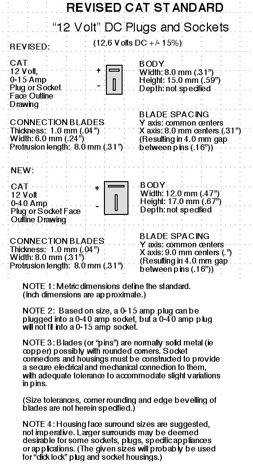
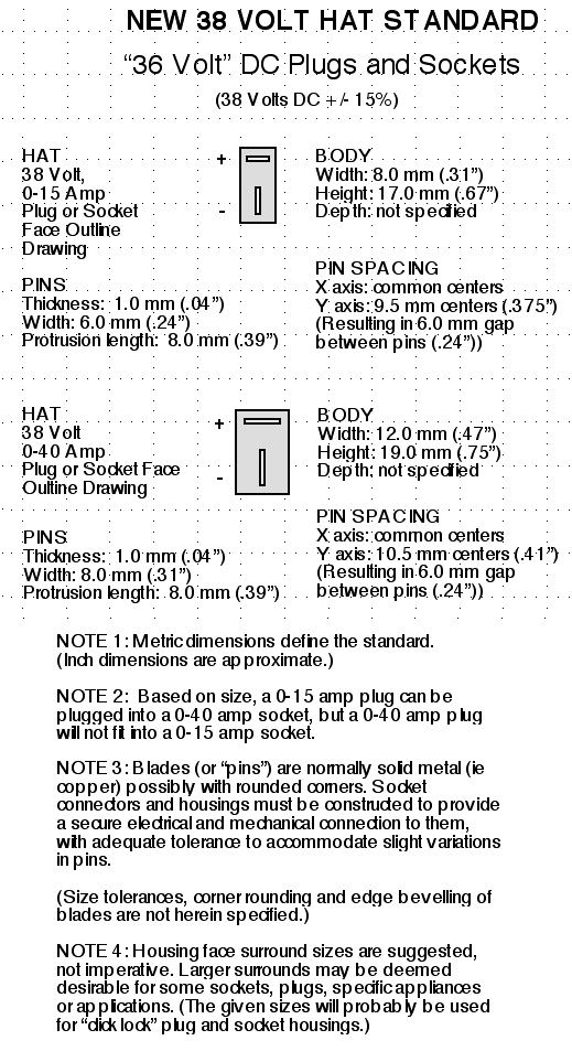 Indoor
Vegetable
Growing With LED Lights (and other gardening)
Indoor
Vegetable
Growing With LED Lights (and other gardening)
When the tomato plants
really started growing near the start of May, they were soon into the
LED light 'bulbs' above. I propped the right hand legs of the light
table onto the dolly they were on, but that solution only added 3" and
was short lived. By the 15th I had to move them out to the greenhouse.
Then the spinach went to seed and also grew up into the lights.
This points out that the LED indoor garden product, if
there is to be one, will have to have lights that are easily adjusted
up and down, preferably in more than one section, to cover seedlings
well or to allow for tall growing vegetables. (A neighbor is planning
to hang his grow lights for seedlings from the ceiling on pulleys.)
Somebody gave me a small coffee plant in a pot. I put it
in the LED garden. I'll see how it'll do indoors with the LED lights,
but the weather around here is nothing like where coffee is grown.
As the lettuce and spinach end in the March box, I'll shut
down the indoor
garden for the summer. The greenhouses are good enough... except that
slugs keep coming and eating tender young seedlings. I haven't had that
problem indoors! Hmm... slug bait...
If LED Indoor Gardens are to be produced as a commercial
product, I think I would team up with a furniture maker. A lot of the
work would be much like making furniture: drawers or cupboards
underneath for storing gardening supplies, supports for lights above
and other wooden or 'prefab' parts. (No particle board. It doesn't
withstand getting wet, and that would be almost inevitable.) The
electrical, LED lights and electronics would be added on to these
cabinets once assembled.
I bought fruit trees in Victoria just before I moved here
and planted soon after I arrived. So this is their first complete
spring. I bought two supposedly "compatible" (according to the nursery)
apple trees, and a "compatible" pair of pear trees, which are intended
to cross pollinate each other. On both fruits, one tree flowered and
finished before the flowers came out on the other. It remains to be
seen which, if any, bear fruit. I may need to find more trees... and
somewhere to put them. Of the
two apricot trees (self pollinating) that I got a few months ago, the
one in the pot looks okay. The other now has a lot of dead
branches. I was concerned about the one in the pot not getting enough
water and watered it frequently, whereas I was less concerned about the
one I'd planted and apparently neglected watering it. But of course its
roots are
still largely in the soil that was in its pot and haven't had a lot of
time to grow out more. Oops.
HE Ray Energy
I had pretty much run out
of ideas by the end of April. Then on the 5th it occurred to me to try
placing a light bulb itself near the coil to see if any RF energy
around the coil would light up the bulb.
Also, it seems to me that it is almost surely necessary to
magnetically saturate the core of the coil or transformer being used.
Normally one does not want the magnetization to go so far. Saturation
is supposed to be the limit. The currents suddenly start to rise when
the core is saturated. In this case and on this small scale, that "EMP"
is needed. That may require not only higher voltage but a
stronger pulse with higher current than I've been using.
On the evening of the 27th I hooked up the coil to the car
again. I disconnected the motor, so the "armature drive" was open
circuit. In that condition I found the field drive would only put out
the programmed "minimum field drive" current regardless of stepping on
the 'gas' pedal. But if I hooked it up the car would start to move, so
I didn't.
With 2 magnets around the coil and the same 40 watt
incandescant "candle" light I got 12 volts instead of 11 (one magnet)
or 2.6 volts (no magnets). That was with 2 amps of "field drive" from
the motor controller. With the programmer I started adjusting the
"minimum field current" upward. Anywhere from 3 amps to 5, the voltage
stayed between 21 and 26 volts, with the higher currents giving the
higher voltages. Further increase to 6 or 7 amps of current didn't
raise the voltage. The motor controller shut itself off before I got to
8. At 4 amps and up it was around 25 volts. I expect the coil was
probably saturated anywhere above 4 amps.
The coil hummed and the filament of the light glowed
dimly. Nothing seemed to get warm or hot to speak of. Two loose bulbs I
placed with their bases in the box to see if they would light up with
RF energy did nothing. (Maybe they need an antenna?) The coil
hummed just as loudly with or without an output load, depending only on
the current driving it.
With the light turned off the DC output voltage rose
slowly
toward around 120 volts. But turning it back on immediately dropped it
back to 25 volts. Where did the 25 volts come from? It was
certainly less power out (25 V * .16 A = 4 W) than was going in: 36
volts * 4 amps = 133 watts. But if it was coming through from the
source simply by transformer action, why did it take a couple of
minutes to build up to 120 volts with no load, and yet it could
maintain 25 volts with a load? And what did the magnets have to do with
it?
Later I tried a 150 watt bulb. This time the voltage
dropped to 12 and the current rose to 350 mA. 12 * .35 = 4.2 watts:
same power. Then two 40 watt bulbs in series made for 29 volts, .11
amps; 3.2 watts. The filaments barely glowed. (One was so dull I had to
close the door to the dull, cloudy daylight to be sure I was seeing it.)
I really should take the oscilloscope out there as
well as just a voltmeter and ampmeter, and check waveforms. There might
be some narrow spike to 120 volts, and it might be just spikes, the
leading and trailng edge of the pulses, being transformed and coming
through from the source. And it just might be worth trying more
magnets, but I don't like to get very many in close proximity - I
already mashed one finger this last week under a cant of wood that was
heavier than I thought.
Finally on the 30th I was reading something about early
radio and I remembered that at least some of the HE ray receivers had
to have a
ground connection. There was definitely something to try!
Nickel-Nickel
with Oxalate Battery Chemie
Cell Construction
Nickel-nickel seems like a very good battery chemistry.
But thoughts kept coming to me that they will somehow be better than I
expect and substantially better than lithium. Call it intuition. On the
night of the 14th I had a dream of riding in an electric car. My
brother who was driving told me he could drive for two days without
recharging because of the nickel-nickel batteries. Could they really be
so much better? There are some hypothetical possibilities. What if
something like lanthanum nickelate forms in the positive, taking the
nickel from valence 2 to 4 and so moving two
electrons per nickel atom instead of one? [That might be La2(NiO2)3...
or
something
along
those
lines]
Or
something
to do with the oxalate? What if hydrogen can be stored in
the cupro-nickel negative, giving it 'double capacity' - hydrogen
storage plus the nickel to nickel hydroxide reaction?
It seems likely to me that they're much better, but I
can't
prove it to others unless I make can good working cells and get the
better
measurements.
Which brought me to the next question: could I actually
make a battery cell that worked, lasted and was practical? I had
recently noticed that while the laundry room had almost no space to
work in, the wide bathroom counter in the next room had some free space
at the right end... a small space to do lab work! So on the 15th I
decided to do what I've been meaning to do for over a month now: take a
few hours and make a "real" nickel-nickel cell, or at least a better
test cell. I did it like this:
1. I found a pill bottle just the right size for electrodes I could
make in a small round electrode compactor I had made who knows when. I
cut the bottom 1" off of the bottle to be the body of the cell.
Negative Electrode
2. I cut a circle of cupro-nickel sheet metal to fit, with a long tab
to go up one side on the inside, as the negative terminal on the top of
the cell at the edge. (no holes to leak except on the top!)
3. I etched the sheet metal circle in (weak?) ferric chloride for about
a minute. This etches away copper faster than nickel, and leaves a
fractally rough, nickel rich surface at the micro or nano scale. This
gives it much
more reactive nickel surface. It looked dark and dull instead of shiny.
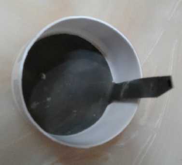
4. I cut two square pieces of nickel foam (~95% air). The corners could
bend and fold over to make them round. The two were 1.6 g of nickel.
(This would make a good conductive interior for the electrode. One
might make the electrode without the nickel foam. Nickel powder flakes
by themselves should be conductive enough. I'll try that later.
Meanwhile... every advantage I can give it!)
5. I measured out some nickel flake/powder; an amount that looked good
which weighed in at 6.15 g. I put one screen/mesh into the compactor
then half the flake, then the next mesh, then the rest of the powder.
Then I folded the corners in over the powder. It sort of made a mesh
basket, so I added one more piece over the top, which would have been
about .6 to .7 g. I thought the electrode might end up 2 to 3 mm thick.

6. I took it out to the hydraulic press and pressed it to 11 Mg (11
metric tons. YAY for a heavy duty press with a gauge on it!). It wasn't
very even - .75 mm at one side up to 1.35 mm opposite, average about
1.05 mm. But it held together like a single disk of lightweight
sintered(?) metal and it certainly looked like a great battery
electrode. It weighed 8.1 g. In theory 8.1 g of nickel should give 3.86
amp-hours. Hopefully it would give 2 or more.
Obviously an electrode 3 times thicker would give 3 times the amp hours
without increasing the weight of the current collector sheet of
cupro-nickel behind. The main limit to the thickness is how much it
reduces the maximum current available, which includes charging current
and hence speed to charge the cell.
Under 40 power magnification the compressed powder surface
looked like gray sand with grooves in it. The grooves were from ridges
on the compactor die's surface, which wasn't very smooth. Where the
nickel mesh was also looked like sand, but with shiny parts that looked
sort of like someone had dribbled water on the sand in places, which
had beaded up.
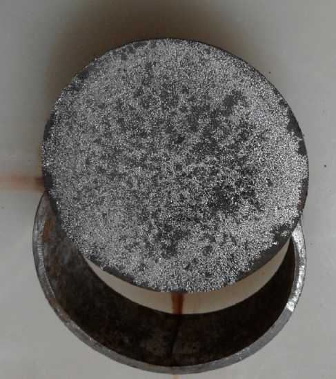
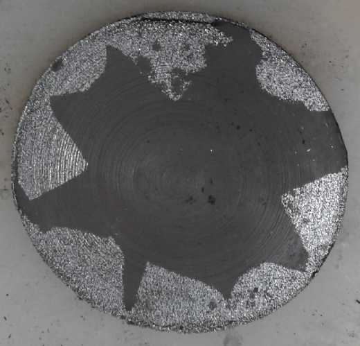
Extra
The backing metal was 11.4 g. If the bottom of the cell
was flat instead of a shaped pill bottle, I could see making thicker
electrodes and just using something like lightweight cupro-nickel foil
or screen under it for a current collector. Or maybe even just the fine
mesh with powder impregnated, no backing sheet. Since I had some powder
and mesh left
over (and I had to do something with the powder - once taken out,
powder wasn't going to go back in the can just in case it might have
become contaminated) I put in two layers of mesh and the powder, then
decided it was too thin and added a scoop more powder. This time surely
I would have a thicker electrode! Well... after a 10 ton pressing it
was about 1.15 mm thick and weighed 10.2 g. This theoretically had
almost the energy storage capacity of a NiMH "C" cell. (A real 5
amp-hour, 85 gram one, not a 2.5 amp-hour "AA" cell in a "C" cell
case!) What would it really be?
The electrodes are 5.2 cm diameter, which is 21.24 sq.cm
so
10 tons is 471 Kg/sq.cm. That's probably a pretty good figure - a
little less than I've heard was used for iron in some nickel-iron cells
(620 Kg/sq.cm(?)).
Positrode
7. I cut a circle of "graphite foil", with a bit of a gap at one edge
for the negative tab to get past. Then I got out the osmium doped
acetal ester and tried to paint it on. It beaded up. I didn't like
that, so I got a piece of "flexible graphite", cut it the same, and
painted it too. On this it smeared and didn't bead up. Later I did a
second coat on both. It seemed mostly to take on the foil the second
time around. (How come it seemed okay on the previous piece for the
test cell? Did I wash that one first or something?)
8. I got out what was probably the best of the
nickel-hydroxide-monel-lanthanum-thiamin powder I made all those years
ago. Here was a bit of a quandry. I had little confidence the loose
powder would hold together the way the negative ones had. On the other
hand I was afraid to add anything to 'glue' or 'gel' it, lest it cause
self discharge. Finally I shrugged and used the straight powder. I put
in 16 grams and compressed it again to 10 tons. (That's probably still
less than a match for 8 grams of nickel in the negative. So what? If it
works, yay!)
It came out about 2 mm thick. I didn't actually measure it
because it seemed too fragile.
And
9. Next I cut a circle of heavy paper as an insulator between
electrodes, and another strip to run up the side with the negative tab.
The circle was a bit bigger because I didn't want anything to short. It
should seal all the way around. I wetted it with Brita filtered
(~=distilled) water so I could fit it around the edges, going up the
sides a bit... then remembered I was using DES and there shouldn't be
any water. I could shape it then wait for it to dry, or make another
one. I made another. It didn't quite cover around one edge so I cut
another little wedge to fill it in.
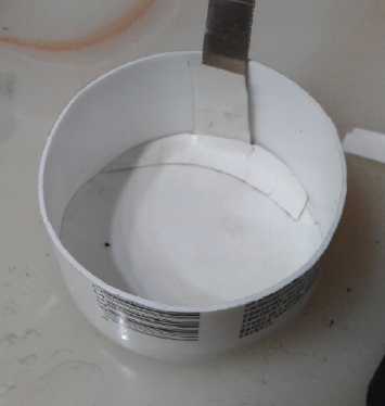
10. I mixed some ethaline DES and potassium oxalate and poured a little
in.
11. I went to put the electrode in, but it was so fragile it slid off
the compactor bottom piece onto the counter and became powder again.
Apparently all 10 tons in the press had done was break up the lumps and
make new ones.
The only option seemed to be to pour the powder into the cell, so I did
that. It didn't all wet, so I added some more electrolyte. That turned
the powder into mud. Perhaps it would "form" with charging and
discharging? That is something some new electrodes do and it's part of
making some cells. (It didn't.)
12. I put the flex graphite piece on top, and found a couple of large
nuts and bolts to weigh it down a bit.
Tests
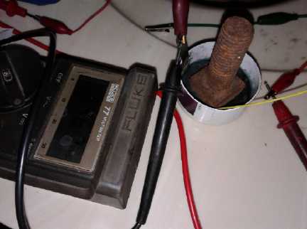 I hooked up my
crappy new lab power supply that didn't
eliminate the need for external meters for both voltage and current,
and set it to 1.7 volts. The cell would only draw 1 mA. I hoped it
would go up as the paper started to saturate, but it only went down, to
.25 mA after 10 minutes. Pressing down to connect the powder better
didn't seem to change it much. It didn't seem to be holding a charge,
which I thought was probably some powder got past the separator paper
and made a bridge between electrodes.
I hooked up my
crappy new lab power supply that didn't
eliminate the need for external meters for both voltage and current,
and set it to 1.7 volts. The cell would only draw 1 mA. I hoped it
would go up as the paper started to saturate, but it only went down, to
.25 mA after 10 minutes. Pressing down to connect the powder better
didn't seem to change it much. It didn't seem to be holding a charge,
which I thought was probably some powder got past the separator paper
and made a bridge between electrodes.
I also discovered that the power supply acted as a small
load when set to "off" or actually turned off. It was perfect for
making one think the battery had a self discharge problem it didn't
have.
I took it apart again. I made up a new separator paper.
This time I wetted it with water and bent up the edges to make a bit of
a dish. I think that's the thing to do - have a paper "basket" up to
the top of
this electrode. Then I left it overnight to dry, but I didn't get back
to it on the 16th.
On the morning of the 17th I reassembled the cell, this
time with the original separator sheet on top of the new "dish" sheet.
(I used the original sheet as a "platter" to hold the mud electrode
together while I picked it up and put it in.)
It didn't seem very promising. It was initially around .45
volts. If I put the large, heavy nut on top the voltage started
dropping. Somehow it was making a bit of a short. I took the cell
apart, found nothing, and put it back together. The large nut still
made it self discharge. I used a smaller, lighter weight that was more
in the center without coming near the edges. That seemed to be the
answer for the time being.
When I put on charge at 1.7 or 1.8 volts, it only charged
at .6 mA. That didn't seem very promising. Nothing ventured, nothing
gained, so I left it on charge. I checked a few times. It gradually
improved over the day. By night it drew 2.5 mA with 1.7 volts from the
power supply. And when the charge was removed it took quite a long time
(3/4 hour?) for the voltage to drop to 1.3 volts. "Short circuit
current" through the DVM started out at 50 mA (dropping rapidly), up
from under 5 in the morning. When put back on charge after being
shorted, it drew upwards of 15 mA, gradually dropping to the 2.5 mA
figure again. It still wasn't much to speak of, but it was far better
than when first connected, and apparently improving by the hour. I set
the charge down to 1.6 volts, which dropped the current down to 1.5 mA,
and left it overnight.
Before I quit I belatedly checked some resistances:
* The (other) compacted nickel powder electrode was pretty much a short
circuit. Whatever factors were preventing amps of currents, the
negative electrode certainly wasn't one of them.
* The graphite foil spare current collector with the osmium doped film
was about an ohm
* The doped flexible "gasket" graphite was under an ohm
* Undoped pieces of the foil and gasket graphite weren't much different
than the doped ones, which indicates that the film must be a pretty
good conductor. It depended more on whether the test leads were pressed
softly against the material (1 ohm) or the points were jabbed into it
(under 1/2 ohm).
What was still unknown was the electronic conductivity of
the positive electrode powder. The resistance was likely - and later
proved to be - very high since I couldn't get it to stay compacted and
I couldn't add graphite or conductive carbon black.
The next morning it had improved a little more. All the
currents had risen only a bit, but left off of charge and dropping
through the 1.3 volt area, self discharge had dropped from around 5
mV/minute to 2.0 and was still lower when it was down to 1.25 volts
(1.25 mV/minute). Instant short circuit current was 75 mA. I came up
with one new metric for testing: "Short circuit current after 10
seconds shorted", which read 29 mA. Currents were read with the cell
fresh off charge at 1.6 volts. They were always lower if the cell sat
until it dropped to 1.3 volts before testing. After being shorted the
voltage would jump back to over a volt in a couple of seconds, take 10s
of
seconds to rise up to near where it had been, then minutes to reach
whatever voltage it was going to reach.
I reduced the charge to 1.5 volts. I was hoping
performance would continue to improve, but currents stayed similar and
only the self discharge continued to gradually reduce. On the morning
of the 19th it still held 1.327 volts after an hour (60.0 minutes -
this is how testing batteries can occupy large amounts of time!), and
was dropping by 1.4 mV/minute.
Sealing the Cell
Something I wanted to try quite soon was to at least
somewhat seal the cell. Would anything change if air was kept out?
(With reaction voltages above nickel's, the negative electrode
discharges when oxygen gets in. Would that be happening with nickel?)
The graphite sheet covered the top... maybe just drip some candle was
around the edges? I tried that and it was quick and easy. (What,
candles have a purpose other than burning buildings down?!?) Heat glue
would probably have worked well too. (The candle wax was easier to
remove later.)
By early evening the cell retained 1.295 volts for an hour, with the
self discharge down to ~1.6 mV/minute in that region. By 1.23 volts
(almost 2 hours), it was less than 1 mV/minute. I don't have an
"official figure" for the expected cell voltage. Eventually it seemed
to be somewhere
around 1.35 to 1.4 volts. That was somewhat higher than I had expected
(~1.25 volts). Around 10% more energy - encouraging!
Water Based Cell
Something else I wanted to try was using potassium oxalate
in water as electrolyte instead of in ethaline DES. Obviously it was
working in ethaline, but currents should be markedly higher in a water
base if it worked. Since I wanted to continue testing this cell, and
having already made two nickel powder/mesh electrodes, I decided to
make another cell. (I must have made that compactor to fit some ABS
pipe or something - what and where was the right one?)
If it didn't work, I could take it apart and let it dry
out, then add ethaline and have a second cell like the first. I
got to it on the evening of the 19th. Aside from the doped graphite
foil for the positive current collector and the 10 gram nickel negative
electrode, I used 20 grams of "+" powder, and I used nickel-brass for
the negative current collector per the idea a ways below.
Instead of starting charging from 1.6 volts at 1 mA it was
about 6 mA. But it didn't seem to work. It discharged itself quickly as
soon as the charge was removed. Why should that be, when the
nickel-manganese cells with the same positive (and double the overall
voltage) more or less worked? It made little sense. I was concerned
that there was a short, but it didn't discharge to zero, only to .47 V
or so. Then I thought of the way the film had beaded up on the graphite
"foil". Maybe it wasn't coated? I would take it apart and redo the
separator paper and use 'gasket' graphite. This time also I would drip
in some candle wax anywhere that looked even slightly likely to cause a
short through the separator paper, notably around the negative tab.
But still the original graphite "foil" had worked in the
cell in March, or I wouldn't have had success and continued
experimenting. But the film hadn't beaded up on that one when I was
painting it.
(I didn't get any farther on this.)
Old Cell
On the evening of the 20th I put the old cell back on
charge. The next morning the self discharge had gone down still further
to about 70-80 seconds per millivolt, maintaining over 1.32 volts for
over an hour. But the short circuit current was also down again, to
about half of what it had been at the best point. (15mA after 10
seconds.) My thought is that it needs more electrolyte - ethaline,
KC2O4 or both. Quite probably the electrodes had absorbed some of the
oxalate. Or perhaps the ethaline was escaping and evaporating or some
had been absorbed. But I hadn't measured it and I didn't know how much
was needed or how much to use in the first place. I would have to
scrape off the wax and add some more of each.
22nd: 1.5 hours 1.303 V; -1.35 mV/minute; 10 seconds shorted: 16 mA.
Summarizing the reduction in self discharge:
day - mV/minute - drops to 1.3 volts after _ hours:
17th: - ~-5 mV/m - .75 hrs
18th: - -2.0 - 1
Then I started measuring "cell open circuit voltage after 1 hour
disconnected from charge" instead of "hours to discharge to 1.30
volts", and the "millivolts drop per minute" was also measured after
one hour:
19th: -1.6 mV/min; 1.327 V @ 1 hr
21st: -1.5; 1.323 (est)
22nd: -1.5; 1.339 V
I decided to take the cell apart, add or change
electrolyte, and redo it. The idea of dripping in wax to seal any
suspect potential leaks between electrodes promised better reliability.
First, I thought I'd run a load test and chart it in
order to have a good comparison with the redone cell. It wasn't very
good - my usual milliamp-minutes instead of amp-hours, and that with
just 500 ohms for a load - around 2 milliamps. Anyway there was nowhere
to go but up!
(
Out of sequence, here with the other figures are figures after
overnight charging with an improved plus electrode from June 1st, AM:
10 seconds shorted: 40 mA. (starting from about 65 mA - it didn't
drop half as fast as with the previous electrode)
-1.1 mV/min; 1.298 V @ 1 hr
By evening:
.82 mV/min; 1.402 V @ 1 hr
Short circuit current was down, but starting from 39 mA it was
still 35 mA after 10 seconds.
)
Remodeled (Old) Cell
I did it on the morning of the 23rd. It seemed plenty wet
so I just sprinkled in more CaO and KC2O4. But I used a new separator
paper, which I made into a deep enough basket to contain the electrode
paste, which came off the old paper in clumps of mud which were easily
mashed and molded to fit.
It started at around .9 volts. If it had been all charged
before, why didn't it come back to around 1.3 volts when reassembled?
This seemed to suggest that only a portion of the paste had been being
charged, perhaps even a small portion. That might be the explanation
for the low performance. But how would I make it more conductive, when
it was a powder that wouldn't compact in a press and adding graphite or
'conductive carbon black' made it self discharge?
I put several weights on top (this time that didn't seem
to cause any shorts) and got higher charging current than before, but
not by a lot. (eg, 2.5 mA instead of 1.5? - all depending on time and
state of charge.) Then I started putting a bit of my own weight on top,
and this helped, and further, the currents didn't go all the way back
down when I stopped pressing. I pressed here and there and soon had it
doing 15 mA at first and 5 mA continuous for a while, a bit later
dropping to 3.5.
It wasn't the two or more orders of magnitude improvement I was ideally
looking for, but it was heading toward one order. But poorly connected
grains in the electrode would also explain it: a connected grain
gradually discharges into an almost unconnected and uncharged one,
which gradually transfers its charge to another uncharged one... In
fact, having a large percentage of the grains poorly or not connected
probably explains everything: self discharge (slow as it is), low
currents, low energy storage, very gradual reduction of self discharge
as more of the poorly connected grains gradually become charged, no
distinct drop-off voltage point during discharge. It seemed to be a
good formula for an electrode, but it isn't a proper electrode unless
all the particles in it connect together electrically.
I was afraid of forcing a break in the separator paper or
in the osmium film in the graphite, and didn't want to push on it too
hard. If the film was broken self discharge would go up with no evident
reason. (Perhaps it was already broken or scratched somewhere and that
explained the self discharge it did have. But the poor powder
connections
would equally or better explain it. I suppose I could try out a new
doped graphite sheet?)
How then to make a positive electrode that works well? It
might just boil down to manufacturing technique. Perhaps if the powder
was wetted with something and compacted in the press the electrode
could hold together compacted until it went into the cell, and the
particles would maintain electrical contact with each other? Then
whatever was wetting it could be allowed to evaporate before final
assembly. And the cell could be assembled with a rigid shell, and then
liquid wax could be injected under pressure above the top electrode,
pressing it down. Or maybe some sort of binder would work, but I
hesitate to try anything that might cause chemical problems.
Some hours later I remembered that with a new dry
separator sheet installed and the old saturated ones removed the
electrolyte might be a bit dry. I hadn't sealed the edges yet so I
simply poured on a bit more ethaline DES. That seemed to up the current
from 3.5 mA to 5, which rose slightly over the next hour (as it soaked
in?) to 5.8 mA. There was still a lot of room for improvements before
it would be doing amps and amp-hours.
After I had slopped in a little more ethaline, the self
discharge went way, way up. After supper I investigated and found
another gremlin in the works. Without thinking much about it, I had put
zinc coated nuts or washers on top of the top graphite sheet to
weigh it down and to connect to it. That was okay as long as it was
dry, but once wetted with electrolyte, zinc is a ~ -1.25 volt
electrode.
So I had a strongly negative electrode shorted to the positive current
collector! That explained why I'd had to use a smaller bolt the first
time: it wasn't causing an internal short: it was wet around the edges
then too.
At some point I measured the pH as about 12-13 when I had
the cell apart. That's the expected pH for water with calcium hydroxide
in it, but I wasn't sure about in ethaline. Very much seemed to work
just the same as in water.
When I put it back together on the 23rd I couldn't stop
rather serious self discharge, even by adding a second separator sheet.
A short seemed unlikely and I had wiped off the excess electrolyte from
the top. I suspected my pressings on the top to compact the powder had
scratched up the osmium doped film on the graphite.
High Resistance Electrode can be solved by VERY strong compaction
On the 30th I took two small, thick pieces of nickel-brass
sheet. I slipped the larger sheet under some of the dry positive
electrode powder, and set the smaller on top. (With wet powder, one
would be measuring ionic conductivity - a false reading for conduction
of electrons.) The powder might have been a couple of millimeters
thick. Poking both meter leads through the powder to the bottom sheet
confirmed I had a short between them, that there was connection to and
across the bottom sheet. Then I moved one lead to the top sheet. Just
touching it the resistance was off scale. With some pressing it came
down to tens of megohms. Pressing heavily on the lead onto the top
sheet, thus pressing powder together, brought it down to the upper ones
of megohms, eg, 6 megohms. I used three pieces of different sizes for
the top, from about two square centimeters to 1/2 square centimeter. I
thought that if I pressed on a smaller one the powder would scrunch
together better and give a lower reading, but they were all very
similar. If I pressed in one corner the powder could be felt crunching
up, and the reading would go down to lower ones of megohms until the
top and bottom pieces touched at the corner and it became zero ohms.
With less powder, perhaps under a millimeter, readings in the lower
ones of megohms were had, but still over two megohms.
Somehow the particles have to be brought into much better
contact with each other and with the current collector sheet, but
without pressing very hard on the separator paper or the coated
graphite current collector. The chemistry is working but the mechanical
aspect needs to be solved. No doubt others have solved it, somewhere.
Is there something that could be added to it? Does it need far higher
pressure - tens of tons per square centimeter perhaps? - to compact it
into a cohesive "briquette"? Does the positive side need to be a thin
film electrode?
I decided to try high pressure. I put some powder on a
sheet of stainless steel, and put the 1 square cm piece of nickel-brass
on top. I put it in the press and pressed it to 5 Mg or 5 metric tons.
The powder formed into a sheet, but it was very brittle and crumbly. So
I tried 10 tons, and it was a little better. Resistance however was
still in the megohms. I cut the sheet in half for 1/2 a square cm and
tried 12 tons That got the resistance below 200 kilohms. Then I tried
cutting it in half again, now for 1/4 of a square cm... actually still
more like 1/2 because the nickel-brass was squashing out thinner... and
pressed it to 10, again maybe 20 tons per square cm. Somehow resistance
was back up into the M ohms. But the tests were getting ambiguous
because the nickel-brass was squashing and the thick piece of stainless
steel now had a substantial dish where the pressing had been. From the
one instance of lower readings it was looking like the idea might just
work.
I cut two pieces of mild steel for upper and lower plates,
the top one about .5 sq.cm. I pressed with 10 tons of force. I made
several tries with 6, 8 and 10 tons. If the top piece stuck to the
piston of the press, good readings couldn't be had - M ohms again.
Probably some loose powder from around the edges gets in when I try to
re-place it on the pressed area. When it stayed in place, various much
better readings could be had, 100 K ohms even down to tens of ohms. 8
tons seemed to work at least once, but 6 didn't. So it might appear
that the pressure
needs to be 16 to 20 tons per square centimeter.
Unless the electrodes can somehow be hammered into form
with heavy blows, effective cells much bigger than button cells aren't
going to be made without a very special production setup to get that
sort of pressure over wider areas. And then they'll have to be treated
very gently or they'll break up again. But it does appear that it can
be done, that practical working cells are possible. After all, others
make nickel hydroxide electrodes, albeit for pH 14 alkaline cells, with
various mixes that don't always include graphite - they must have at
least similar challenges. Later I remembered that, yes, Edison had had
the same problem in his tall, flooded nickel-iron cells, to the point
where he made the plus electrodes the size and shape of a pencil in
perforated nickel-plated or nickel metal tubes, repeatedly loaded from
the top end with a few more grains which were each pressed in with tons
of force. In the less alkaline cells metal isn't an option unless it's
perfectly coated with the conductive film. Any break in the film and
the metal would corrode away.
On the 31st I thought of the jeweller's rolling mill.
These are made to flatten or shape strips of softer metals such as gold
and silver. Perhaps somehow I could contrive to have it compact a thin
strip of the powder? It could be done in more than one pass, perhaps
with textured rollers so it was only flattening part of the material at
a time. Could it bring enough pressure to bear to accomplish the task?
Even nickel-brass, being harder than regular brass, was a challenge for
it. But maybe, with a thin enough strip?... but only if I could figure
out a way to feed the material in and not have it break up in the
process.
Then I went over to my neighbor's for a chat. I noticed he
had some heavy rollers for heavy equipment and so I explained the
problem and the idea. He said rolling would tend to spread material and
thought it would be easier to get the pressure if I put a heavy pin
inside the same cylinder as an axle and pressed on it. Then I thought I
might just get that instantaneous pressure if I hit the pin with a
sledgehammer or maul instead of using the hydraulic press. He said to
put something inside like cardboard or tinfoil so it would release
after I had done something like that. (It turned out not to need it.)
He said that cylinder was spare and so I took it. (The pin wasn't a
spare, unfortunately.) It was 38 mm inside diameter, making it 11.34
sq.cm surface area - about half the size of the previous sets.
I checked out a trailer stub axle I had and it seemed to
be a pretty good fit, a bit too short, if I chopped the thin end off
it. Then the widest part would be the bottom and it was pretty much
just the right diameter - slightly undersize. The shaft I'd be
hammering on was a little thinner yet, so it wouldn't get stuck if it
mushroomed out a bit wider. 'Too short' just meant using a bit longer
"plug" in the bottom. Now... what did I have for that plug? Not finding
anything that looked like it might work, I went back to the neighbor's
and I got a very large bolt. The shaft was too small, but even the
small sides of the hex head were too large. It must have been
very hard steel, even harder than the stub axle, because I ended up
taking hours to turn the head down to size on the lathe, and I stopped
to sharpen my carbide tool about 4 times. But as the squashed metal in
my previous pressings had shown, harder is better - as long as it's not
brittle!
Then I took it outside and measured up 20 g of the powder.
This made about 8 or 9 cc. To this I mixed in 2 cc (.8 g) of pottery
supply "Veegum" (a mixture of bentonite clay) as a 'glue' or binder. I
poured it into the cylinder with the shaped bolt underneath - I'd made
it a close fit and it would lose little powder around the edges. To
make a long story short, pounding on a relatively hard part of the
gravel driveway with two heavy blocks of steel under the "compactor
unit", it finally felt like I was hitting something solid and didn't
bounce much. (It bounced badly on a big "solid" tree stump.) I walloped
it pretty hard but I didn't want to risk missing the pin or hitting it
on the edge. It was enough that the "tool steel" axle soon had dings
and a bit of mushrooming on the end. I threw in a bit of metal and
measured through the powder to the outside metal. It seemed I had it
down from over ten megohms to under one. It was disappointing, but at
least it was an order of magnitude improvement. Another factor was that
it was about 2.5 to 3 mm thick. Thicker electrodes have more
resistance. I miscalculated in doubling the powder, when the surface
area was half. Since I used twice as much powder, added the Veegum and
the electrode was half the area, I shouldn't have been surprised it
came out so thick. I also added a few drops of Sunlight dishsoap when I
was compacting it to help glue it together - not much; it was still
pretty dry. This one held together well which I attribute partly to it.
The lathe had left a lot of grooves on the critical end
surfaces, too deep to polish out. Since they weren't mirror smooth some
compacted powder ended up stuck to the dies. And of course there were
ridges on the compacted electrode where the grooves were. (I filed the
dies down and re-polished them on June 1st. A few deepest grooves
weren't entirely eradicated and they still didn't have that mirror
smooth surface, but they were close enough.)
I put the new electrode into the same cell, removing the
original one. Charging current was around 4 mA. That was disappointing
but better than 1 or 2 - and it was from a 3 times thicker electrode
with half the surface area. If it had been the same dimensions it would
probably have been around 10 mA: the order of magnitude improvement
expected from the lower, but still much too high, electrode resistance.
And of course it would help to make a new cell with
diameter to match the electrode so it couldn't mush out around the
edges.
For a while the self discharge was awful. Since I had
painted the conductive film on both sides of the graphite sheets, I
flipped this one over. That cured the problem. (Doubtless the regular
cure would be "do not disturb" once the cell is assembled.) The Veegum
and Sunlight soap didn't seem to be any problem as this electrode
worked better than any other so far.
If I do the same thing with a still smaller die, I should
be able to get more pressure per square cm when I hammer it. Or maybe I
should have a bigger hammer - 10 pounds instead of 6? Or a better
system - a 20 pound weight in a track coming down squarely on top every
time, with the die on a heavy, solid base, might do the trick. In fact,
just setting the die on a big rock instead of on gravel might make the
difference. (It didn't.) Perhaps for test cells one could have a pipe
to control the fall of the weight, and drop it down the pipe onto the
die. If reaching up and dropping the weight into the pipe doesn't
initially do it, get a longer pipe and a ladder to drop from higher up.
It just has to get to that threshold pressure of 20 tons
per sq.cm, even for an moment, over a much broader area than .5 sq.cm.
(Or else do something like spit out tiny electrode "pellets" at a rate
of at least several per minute, which would be placed side by side
until an electrode area was filled. Ugh! Or Edison's "pencil electrode"
system, but making rectangular shapes? That sort of "end feed" layout
certainly reduces the cross section that needs to be pressed. Get it
down to 1/2 sq.cm - even if it's 10 cm tall - and a hydraulic press can
manage it. But the die had better be stronger than mild steel!)
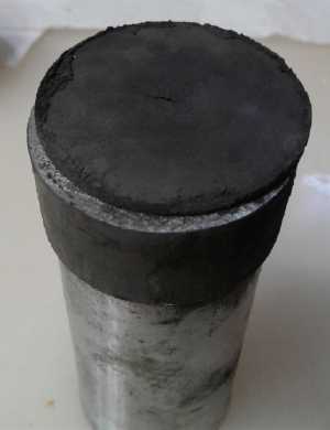 But on the
morning of June 1st the cell had had overnight to charge and so was
working better, so I continued the experiment. I opened it and found
the plus electrode - the whole electrode and not bits of mud - was
stuck onto the graphite. Since the compaction was only marginally
better I attribute it holding its shape to the Veegum and dishsoap. I
added more electrolyte so it was pretty soaked instead of a dry cell.
Currents immediately doubled. After a while charging current was down
to 5 mA, but that was after doing some charging around 8 mA for a
while, so the electrode was getting better charged faster. (And it's
still better than 1 or 2 mA.) Short circuit current started out at
around 65 mA and didn't drop off as fast as before after 10 seconds
(still 40 mA). By evening everything was even better with better
figures than with previous electrode - except that currents were lower.
However, the drop in current over ten seconds during a continuous short
circuit was much lower too. It just kept putting out. The drop in self
discharge may be the improved electrode, the reduced surface area, or
just fewer scratches or gaps in the doped film coating the graphite.
(Figures are given above, along with those of the previous electrode.)
But on the
morning of June 1st the cell had had overnight to charge and so was
working better, so I continued the experiment. I opened it and found
the plus electrode - the whole electrode and not bits of mud - was
stuck onto the graphite. Since the compaction was only marginally
better I attribute it holding its shape to the Veegum and dishsoap. I
added more electrolyte so it was pretty soaked instead of a dry cell.
Currents immediately doubled. After a while charging current was down
to 5 mA, but that was after doing some charging around 8 mA for a
while, so the electrode was getting better charged faster. (And it's
still better than 1 or 2 mA.) Short circuit current started out at
around 65 mA and didn't drop off as fast as before after 10 seconds
(still 40 mA). By evening everything was even better with better
figures than with previous electrode - except that currents were lower.
However, the drop in current over ten seconds during a continuous short
circuit was much lower too. It just kept putting out. The drop in self
discharge may be the improved electrode, the reduced surface area, or
just fewer scratches or gaps in the doped film coating the graphite.
(Figures are given above, along with those of the previous electrode.)
A discharge test in the evening was still low capacity,
again demonstrating that I still didn't have enough compaction of the
electrode, but this time it held its voltage better under load, and
when the test was ended it recovered its voltage much more rapidly. It
showed rather similar voltages to NiMH cells, maybe even a touch
higher. I thought NiNi would be about .1 volts lower, nominally "1.1 V"
instead of "1.2 V", but that didn't seem to be the case. The load test
started out at well over 1.3 volts, and the voltage dropped off rapidly
once it hit about 1.15 volts. On the morning of June 2nd the voltage
was still 1.368 after 3 hours off charge, showing that whatever the
self discharge is, it's not inherent since that was at least an order
of magnitude lower. And that's with an unsealed cell where air might
reasonably be expected to cause self discharge. But it was definitely
time to quit experimenting for now and get this newsletter of May's D
& R out.
NiNi Must Next Move to Developmental
Production
It certainly appears that the last challenge to making
working cells is to greatly reduce the very high resistance of the
powdery positive electrode
material, by very high pressure compaction. That resistance perfectly
explains why my cell, though
working chemically,
performed pathetically, and this was supported by the somewhat improved
performance of the new electrode with somewhat better compaction. The
challenge now is not to invent the
nickel-nickel battery but to invent a practical way to produce good
positive electrodes. (I think I've figured out a workable way for a few
test cell electrodes as I do a final edit of this newsletter.)
Preferably production after that is something that should
be approached in a reasonably big way. Not only the compaction but many
or most of the processes need to be automated to prevent production
bottlenecks. People are definitely going to want millions of them once
they become available and known. They will want to switch from lithium
types, which are being manufactured in great quantity today. Electric
vehicle manufacturers will be chomping at the bit for them, as will
"off grid" sites and marine battery users. It will not be possible to
satisfy global demand from even a very large, high production factory.
Negative Current Collector Metal as a Hydride for double energy
storge?
Usually to make a good metal hydride, big chunky atoms
like lanthanum are alloyed with nickel to achieve the maximum
inter-atomic spaces in the crystal for storing hydrogen ions - protons.
But might cupro-nickel have some amount of proton storage capacity?
NiMH cells
are pH 14 alkaline, in which nickel won't oxidize, so no reaction of
the nickel to oxide occurs. Either the nickel-lanthanum alloy stores
protons or it won't work. But in fact, in such hydrides the hydrogen
ions can be packed in more densely than the density of actual liquid
hydrogen. Apparently theoretical storage capacities upward of 1000
AH/Kg can be attained. I have little idea what is actually attained in
practical commercial cells, but from the weight of a 10 amp-hour "D"
cell, I'd guess it's probably under 300 or so.
The nickel-nickel cell operates at a somewhat lower pH
where nickel will oxidize to hydroxide, giving us the 477 AH/Kg of Ni
storage figure
for the nickel exposed to the electrolyte. But the interior of the
backing sheet isn't exposed to the electrolyte. If in addition to being
a backing sheet it can store protons, its storage capacity would be
much increased.
But owing to the nickel also reacting, lanthanum would
quickly corrode. So my thought
is to add some tungsten, lead or bismuth instead: other big chunky
atoms with
low reaction voltages (I haven't checked out which ones might work as
to reaction voltages, much less as to other characteristics)
that won't corrode like lanthanum with its very
high reaction voltage. Even if it doesn't attain very high values
like 300 AH/Kg, any amount
just adds more storage capacity to the nickel's reaction energy. Maybe
it can attain nickel's full theoretical 477 AH/Kg or higher. OTOH I
really know little
about metal hydrides. Only that for good ones it gets complicated with
cobalt and other rare earth additives to keep the lanthanum from
oxidizing.
If hydrogen/proton storage energy can be added to
nickel reaction energy, it will be a heck of an energetic electrode!
With the nickel reaction being slightly lower negative
voltage than hydrogen storage, the cells can be vented without issue.
But cells with hydride storage have to be sealed and withstand a
certain amount of pressure. Air (oxygen gas) getting in would turn the
protons spontaneously back into OH- ions and H2O - self discharge.
In 2008 I bought some nickel-brass (AKA "nickel-silver" or
"German silver" -
Cu:Zn:Ni eg, 65:18:17% - contains no silver) sheets for current
collector plates. Then I realized that zinc as a negative electrode
gradually deteriorates. Zinc has a soluble state ("zincate" ion) that
seems to apply at any pH, and the atoms migrate while it's in that
state. In a battery this state is short lived and the zincate turns
into zinc oxide, but owing to it migrating, the electrode loses active
substance and grows "dendrites" (slivers of zinc) that often short the
cell through the paper. (Cadmium, under zinc in the periodic table,
does it too if evidently somewhat less, and many NiCd cells end up
shorted.)
So I switched to monel (Cu:Ni eg, 63:37%) or other
cupro-nickel (eg 70:30%) to avoid zinc. But this might have been a
mistake. First there's only ~18% zinc in nickel-brass and second if we
don't charge the cell to the higher reaction voltage of zinc, it will
become zinc oxide and stay in that form. If the zinc did migrate out of
the electrode, it would leave the surface pitted and rough - just what
an electrode wants, to have the most surface area in contact with the
electrolyte. I doubt enough zincate would migrate into the paper to
short out the cell. If some zinc made it to the positive electrode it
would simply remain there as oxide.
http://www.TurquoiseEnergy.com
Haida Gwaii, BC Canada