Turquoise Energy Ltd. News #121
covering June
2018 (Posted July 3rd)
Lawnhill BC Canada
by Craig Carmichael
www.TurquoiseEnergy.com
= www.ElectricCaik.com
= www.ElectricHubcap.com
= www.ElectricWeel.com
Features:
* Stable Zinc Electrodes, The "Holy Grail" of battery making...
hundreds have tried and (more or less) failed: Grail TAKEN by new
electrolyte!
(See Month in Brief,
Electricity Storage)
* New Bandsaw Mill Concept: Self-Correcting Band Angle always cuts
straight! (See Month in Brief, Other "Green"
Projects)
Month
In Brief
(Project Summaries etc.) - Band mill - Band - Batteries! -
"Electrafest":Portable 6 KW J1772 EV charger
In
Passing
(Miscellaneous topics, editorial comments & opinionated rants)
- Battery Commercializations?...Useless SDTC Again-Changhong-DIY
Crowd-Factory? - Crystal Sponge? - Moles and hydrocortosone cream:
Update - Feeding the 9 Billion? - After the Thugs (bad poetry that
doesn't rhyme) - Age of World?
- Project Reports
-
Electric
Transport - Electric Hubcap Motor Systems (no reports)
Other "Green"
Electric Equipment Projects
* Carmichael Mill ("Handheld Bandsaw Alaska Mill")
- "railway" band guide wheels: Mounting, adjustments & Cuts
- Self Correcting Band Guides?
* Proposed New Electrical Standards "RFC": a new standard Voltage
(38/36 VDC) +
Standard Connectors for 12 VDC, 38 VDC
- Idea: If making 38/36 volt connectors, why not market 38 volt
lights and appliances along with them? - Other notes
Electricity Generation
(no reports)
Electricity Storage -
Turquoise Battery
Project (NiMn, NiNi, O2-Ni), etc.
* Zinc: notorious battery electrode substance, TAMED by the new
electrolyte!
* Nickel-Zinc Batteries - Compacting electrodes - Glue &
Jell - Why, suddenly, Zinc instead of Nickel?
* Manganese-zinc & Lead-zinc cells & experiments (They all
work!)
* Zinc Sheet Electrodes work great - Shaping Plates to gain More
Surface Area
* Mn-Zn cell from scratch: works great!
This month is mainly about battery
experimentation and development. Now that I'm having real successes it
seemed like a good thing to concentrate on and I spent most of the
month on it. (More below.)
Notwithstanding that, I did just a bit of work on the
bandsaw mill guide wheels near the end -- and on the 30th conceived of
what I believe will be a real breakthrough in band mill design: place
the guide wheel pivots in front of the blade (instead of behind it) and
have spring mounted adjustments instead of solidly fixed. Then the band
will continuously adjust its angle of attack to keep cutting straight
and never veer off up or down (even if the blade is dull), which is the
main and very serious complaint I've been hearing for all band mills
whenever the subject is mentioned. With a single stroke, this should
raise the general liking for band mills among those who've milled wood
from maybe a 3 to an 8 out of 10. It's going to "Wow!" people.
I also said I'd play my Supercorder (the flute instrument
I developed 2003-2006 - www.saers.com/craig/recorder/
) in a couple of songs with a small band on Canada day, July first.
Practice and daily rehearsals took up much time in the last week - with
a half hour commute each way (in the electric Nissan Leaf, of course)
adding to the time. They didn't want me to use sheet music in the
concert and I've never played a "fixed script" without reading the
music before, so they were trying to teach an old dog new tricks and it
didn't go very smoothly. Then in the concert things went really awry
when the sound guy came up and wanted to adjust my microphone while we
were playing, talking to me and breaking my concentration in my most
prominent song. I missed my entry and played some wrong notes in the
rest. But the audience seemed to like it anyway, and (from the movie
"Star Wars")... "It's not my fault!"
Batteries!
Assembling
nickel-zinc
cell
 I started the
month by looking at some charts - Pourbaix
diagrams. I forget why. I hit zinc (just before zirconium) and suddenly
realized that zinc would work as
an everlasting negative electrode with the electrolyte I had come up
with. A long life zinc electrode has been a "holy grail" of battery
making ever since batteries were first made. Many have tried, but no
one has
had real success. Batteries with zinc are single use or
notorious for their short cycle life. Thomas Edison picked nickel-iron
instead of nickel-zinc to get a battery that would last, in spite of
iron's lower energy storage and poorer performance. A web search will
reveal many past and current attempts to make zinc electrolytes work,
or at least to last a few hundred charge-discharge cycles - mostly in
pH 14 alkali. For example, a Journal of the Electrochemical Society
article from 1991 cites ten previous articles on the subject and below
it is a list of 21 newer articles citing it.
I started the
month by looking at some charts - Pourbaix
diagrams. I forget why. I hit zinc (just before zirconium) and suddenly
realized that zinc would work as
an everlasting negative electrode with the electrolyte I had come up
with. A long life zinc electrode has been a "holy grail" of battery
making ever since batteries were first made. Many have tried, but no
one has
had real success. Batteries with zinc are single use or
notorious for their short cycle life. Thomas Edison picked nickel-iron
instead of nickel-zinc to get a battery that would last, in spite of
iron's lower energy storage and poorer performance. A web search will
reveal many past and current attempts to make zinc electrolytes work,
or at least to last a few hundred charge-discharge cycles - mostly in
pH 14 alkali. For example, a Journal of the Electrochemical Society
article from 1991 cites ten previous articles on the subject and below
it is a list of 21 newer articles citing it.
But in my pH 12 electrolyte zinc should last forever. Zinc
has high
voltage and energy per kilogram. In developing the pH 12 electrolyte
with oxalate to use with nickel (or possibly manganese), I had taken
the grail without realizing it! In fact, the electrolyte is
key to a number of potential better chemistries, mostly best using zinc
for a negative side.
So I made a zinc electrode with nano-zinc flake/powder and
traded out the nickel negative electrode for it. But the voltage being
higher meant that oxygen had to be kept out of the cell, or it would
spontaneously convert ("discharge") the zinc to zinc oxide. And I
wanted to get better
compaction on the plus electrodes. I found a compactor I had made
previously that would do that. It made square electrodes instead of
round. So next I made a whole new, square battery cell. (I could use
the 3D printed cases I developed quite a while back along with this
compactor.)
Concurrently with these great chemical finds and results,
I started
putting "stuff" into the electrodes to help hold them together as
thickeners, binding agents and gels. With successful electrodes to
compare with I could tell if the additive(s) were causing a problem.
They helped.
There was still a self
discharge problem in each cell I made, including in the manganese-zinc,
and that chemistry is noted for low self discharge. So it could hardly
be inherent in the electrode chemistry. By process of elimination with
the various cells I made, it finally seemed it must be my cheap
"pottery supply" calcium carbonate, converted by me to calcium oxide in
my mini kiln 6 years ago (TE News #47, #66). It pretty much had to be
contaminated, probably with nitrates. I ordered some guaranteed pure
stuff from Westlab chem/lab supply. I look forward to batteries that
hold their charge for weeks or months instead of hours. (How many years
has this been an ongoing concern of mine, which I've attributed to
other things or had no explanation for? Finally the light dawns...)
But the main thing was I had a great working chemistry
[and soon three of them] that
could be produced one way or another. Fantastic! Now, how to get
production happening?...
On the 5th I e-mailed SDTC (Sustainable Development
Technology
Canada) to tell them Canada could freely have this fabulous new
"created in Canada" battery
chemistry. But Canada didn't want this once in a lifetime opportunity.
An inventor with an invention, however Earth-shattering, doesn't
fit their Procrustian profile of a "well organized and supported
innovative
company" for funding. They don't even pay lip service to inventions and
they don't want to talk to inventors. Is that how to foster development
of new sustainable technologies? I have written of how they put the
cart before the horse before in TE News #80, and I've written more
again below in In Passing.
The next day I e-mailed to Sichuan Changhong Batteries in
China (to "the president") and pointed out the new chemistry they could
freely have. Given their current obsolescent line of flooded alkaline
cells - nickel-iron, nickel cadmium and nickel-metal hydride, made on
their production line bought from Varta in Sweden or Germany many years
ago when they ceased production there, I felt this was one company that
might be in need of
a new battery like this. They would be much more likely to adopt it
than
a lithium or lead-acid battery maker (who would more likely just wish
it would go away!), and their "green" markets
would really appreciate them. (Of course, their markets would then
start expanding, too, instead of shrinking!) So far I have received no
reply. They'll get a pointer to this newsletter, too.
Nickel plus electrodes would be great for a mass
production line, but so far seem hard to do for a homemade battery
because of
their
high voltage. (more experiments!...) So, what about other elements? The
ones that come readily to
mind are lead and manganese. I soon had a battery that worked well
using the manganese electrode of an old "F" size dry cell (found in 6
volt
lantern batteries). And I bought a new lead-acid battery to
get lead positive plates from. I got some good results from these with
zinc negatives in the new electrolyte.
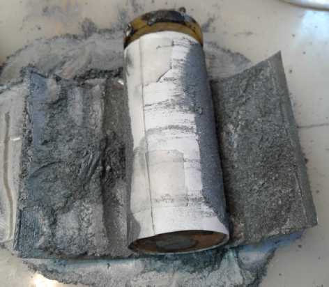
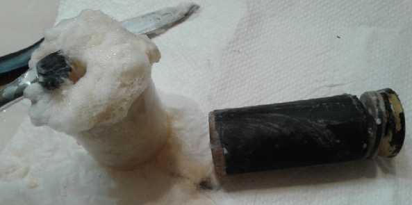
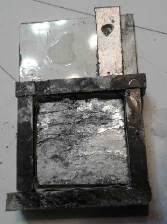
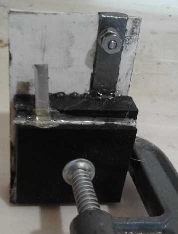
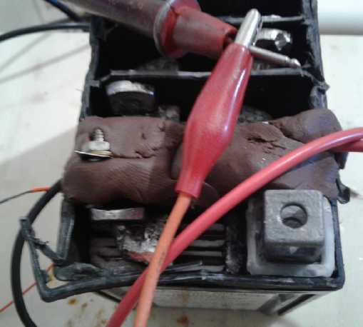 L: Remaking manganese-zinc "F" cell with new
zinc nano powder electrode and the new oxalate electrolyte
R: Testing first lead-zinc cell in original
lead-acid battery case
L: Remaking manganese-zinc "F" cell with new
zinc nano powder electrode and the new oxalate electrolyte
R: Testing first lead-zinc cell in original
lead-acid battery case
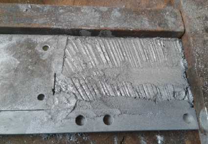
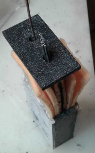
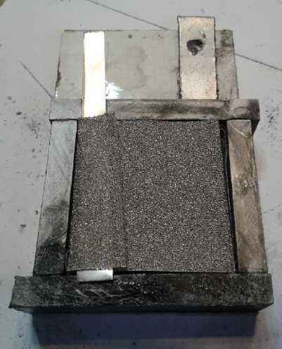
Manganese-zinc flat plates
cell from scratch.
(Outside padding is because cell didn't fill case.)
This worked very well and will probably be
the pattern for battery production - if I do it.
 But I started thinking rechargeable, "everlasting" Mn-Zn
would be the batteries to make at home. Much the easiest to make, CHEAP
materials, and higher energy density than lithium types. It would seem
that all that's been missing for 150 years to have a lightweight, high
energy, low cost and long cycle life battery was an appropriate
electrolyte. And I probably wouldn't have found it either if it hadn't
been for someone giving me an old kid's chemistry set with a small
bottle of oxalic acid in it. I started with that name, years ago.
But I started thinking rechargeable, "everlasting" Mn-Zn
would be the batteries to make at home. Much the easiest to make, CHEAP
materials, and higher energy density than lithium types. It would seem
that all that's been missing for 150 years to have a lightweight, high
energy, low cost and long cycle life battery was an appropriate
electrolyte. And I probably wouldn't have found it either if it hadn't
been for someone giving me an old kid's chemistry set with a small
bottle of oxalic acid in it. I started with that name, years ago.
I put this out on two "DIY"
battery related e-mail lists, and I'll post a link to this newsletter
as well.
But maybe,
since most people obviously would rather buy batteries than make them,
I should set
up a small production plant here? Along with the regulated voltage
chargers they would need. "Prismatic" cells made with multiple plates
stacked end to end (similar to lead-acid batteries) yielded excellent
results in my experiments. They would be 1.5 volts. A factory is easier
to
accomplish with funding. And someone tells me he saw on BBC that
battery factories are presently the world's biggest factories. There's
stiff competition even if one has the "better mouse trap". It would be
typical these days of well established companies to pull some sort of
hi-jinks (bribing government to pass some prohibitive regulation or tie
the company up in court on some pretext with a "stop work" order in
place, devious legal and business maneuverings, criminal threats and
violence in various forms...) to have such an upstart shut down before
it got far onto the public radar screen.
But one can't worry too much about such possibilities.
Hopefully nothing will happen. I'll fill out an application with a
place in BC that has "Executives in Residence" to help manage a new
business, and see how far I get with that.
Saltspring Island "Electrafest" & Portable 6 KW Charger
 In other news, Tom Sawyer sent me pictures from the "Electrafest"
electric transport gathering on Saltspring Island. He said an entire
ferry trip to the island was fully booked with electric cars and not a
single gasoline vehicle. He also says that the price of a 2015 Nissan
Leaf like mine has gone from 18000$ to 23000$ (in 6 months). People are
catching on
and there are few electric cars to be had at the dealerships. Mostly
they're pre-sold, right into next year. Of course, in Victoria driving
distances are generally pretty short compared to on the sprawling
mainland so they're more practical. (When the better batteries start
being incorporated into cars, the continent will want them too!) On
Saltspring Island, from the sounds of things most everybody has an
electric car; mostly Nissan Leafs.
In other news, Tom Sawyer sent me pictures from the "Electrafest"
electric transport gathering on Saltspring Island. He said an entire
ferry trip to the island was fully booked with electric cars and not a
single gasoline vehicle. He also says that the price of a 2015 Nissan
Leaf like mine has gone from 18000$ to 23000$ (in 6 months). People are
catching on
and there are few electric cars to be had at the dealerships. Mostly
they're pre-sold, right into next year. Of course, in Victoria driving
distances are generally pretty short compared to on the sprawling
mainland so they're more practical. (When the better batteries start
being incorporated into cars, the continent will want them too!) On
Saltspring Island, from the sounds of things most everybody has an
electric car; mostly Nissan Leafs.
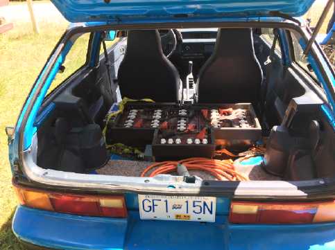
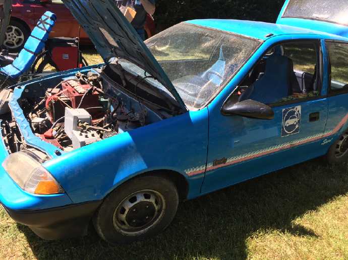 A donated Chevy Firefly (2 door version of my
Sprint)
A donated Chevy Firefly (2 door version of my
Sprint)
converted to electric by Saltspring Island high school class.
I'm not sure about the motor but it looks like they've
kept the original manual transmission and gear shifting.
Back seat removed - lead-acid batteries
are heavy and take up a lot of space.
Probably the most
interesting thing
there was a 6 KW EV charger that instead of installing, one plugs into
a 240 volt dryer plug. I'm not sure I want to buy one because those
plugs aren't everywhere and are usually hard to get at. But if there
was one available anywhere in Masset, perhaps at the town hall, I'd be
able to drive there in the Leaf, charge a while while I did my shopping
or business, and then have the range to return home. Then they would
only need to buy the unit - no electrician and costly retrofit
installation.
(And maybe I could drop the insurance on my Toyota Echo
for part of
the year - bigger savings on this "administrative" item than on fuel.
Of course, I don't always know in advance when I'll want to pull a
trailer. ...Maybe I should ignore recommendations and put a hitch on
the Leaf for my lightweight trailers? Insurance for two vehicles, one
of which is hardly ever used, really costs.)
Also remember that dryer plugs and 240 volts can be
hazardous.
People get electrocuted plugging/unplugging dryers in damp laundry
rooms. That's another reason not to carry one around in the car: if
they get condensation on them around the plug they could be lethal.
It's best if they're kept in a dry, heated space. And this of course is
why
the J1772 charging plug was created in the first place. The power
doesn't come on until and unless the socket is securely plugged into
the car, and there's a ground fault detector. (It still galls me that
there's no neutral provided for plugging in 120 volt chargers. It can
probably be tricked, perhaps by using the metal box or actual ground as
a neutral.)
Maybe I'll volunteer to put up some of the money for
Masset to buy one for the town hall or other conveniently situated
building.
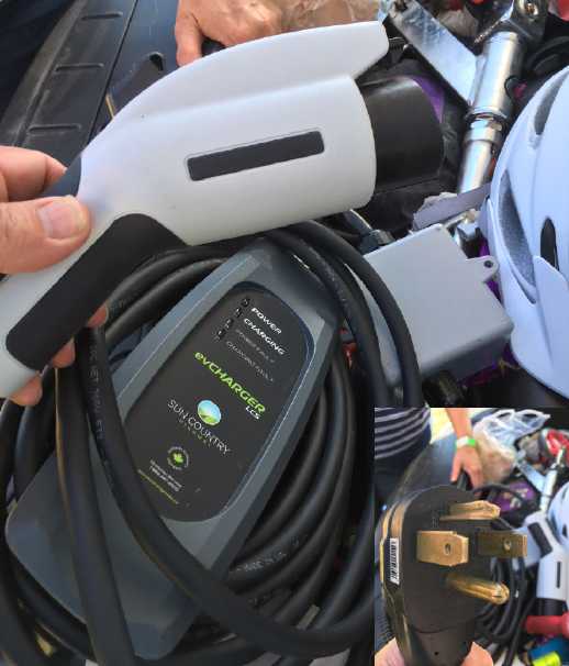 "Portable" J1772 - 6 KW charging unit plugs
into 240 volt, 30 amp (dryer/welder) wall outlet.
In Passing
(Miscellaneous topics, editorial comments & opinionated rants)
Battery Commercializations? - Useless SDTC Again - Changhong - DIY
Crowd - Factory?
Regardless of my own troubles making nickel electrodes,
I'm sure
there are people out there who know the best ways to make them, and
also how to set up mass production lines (actually I know someone).
With funding one can hire talent. The chemistry worked, and everything
else would surely come together as needed if there was commercial
interest. But putting that together by myself seemed beyond me.
On the 5th I e-mailed SDTC (Sustainable Development
Technology
Canada) to tell them Canada could freely have this fabulous new battery
chemistry and technology, created in Canada. But the chance of a
lifetime for starting a
fine new
Canadian industry ahead of the world was passed up on a technicality:
An inventor with an invention, however Earth-shattering it is, doesn't
fit their profile of a "well organized and supported innovative
company". I said I could help set up the production facility, but that
I was an inventor, not an entrepreneur. But they don't want inventions.
It is my belief that to do this sort of thing is exactly why parliament
created SDTC in the first place - the very sort of thing the
legislators had hoped would happen, and that parliament probably left
them a pretty free hand as to how to go about it.
Their self-imposed (I believe) rules don't allow them to
simply say (after evaluating the technology, of course), "Parliament
created us for the purpose of seeing that sustainable energy
technologies are developed and commercialized within Canada. Here is a
fine new invention
that Canada should want. Let's make it happen!" If they won't do that,
99% of sustainable energy inventions will simply not be developed, or
commercialized if they are, just as was the case before SDTC existed.
With a new
enterprise the funds can certainly be committed piecemeal based on
progress, so
large sums aren't being gambled on a single impression. And once an
enterprise is profitable, the funding can be repaid directly or through
taxation of an industry that wasn't there before.
In fact, why are they not out there simply hiring the
people for a "technology development park(s)" to move desirable
sustainable energy technologies forward from ideas to prototypes, so
they can then go to production? Their funds would go toward product
development; their staff would have inventors, innovators and engineers
who could work together to accomplish more, instead of just
bureaucrats. This would soon attract a retinue of business people,
investors and entrepreneurs looking for a product or products to base
new businesses on and invest in. Instead the agency has no goals or
road map, no plan... no clue. It doesn't foster development of
desirable technologies or recognize golden opportunities when they are
shoved in its face. SDTC is supposed to take the lead for fostering
renewable
energy in Canada, but not a trace of leadership seems to emanate from
it.
I have written of this before, especially in TE News #80
after
attending an SDTC seminar that supremely disappointed a whole room full
of some of Victoria, BC's most innovative and active green energy
inventors and product developers. To meet their criteria for funding,
it seemed one would have to have a million dollars to start with, and
would be blowing money out the windows left and right to maintain a
facade of a prosperous company, a "going concern". The truth is it
isn't a "going concern" until the product is for sale. The funding (as
I've
seen happen before) would be used up creating and maintaining the image
complete with
superfluous
office staff, without the proponent ever being able to put it to its
intended use of developing the product. Most of the room would have
felt it was a dream come true if they had anything like a million
dollars to develop their product, and would have been off working on it
instead of attending a funding seminar in the vain hope that someone
might
actually provide even a little seed money.
In spite of a few improvements since that time, SDTC is
then merely a supplemental funding source for
large established companies, from which tens or even hundreds of
millions of
dollars may be sucked by having a "rent seeking" department to put
together carefully tailored fund seeking proposals for
things the company was probably going to do regardless. Is this good
use
of our
tax money? It certainly uses it up in bulk for the benefit of just a
few projects that already have other funding.
The best the contact I reached at SDTC could do was point
me to a
couple of other groups. I checked out one, a "green chemistry" group.
It was set up with pretty much the same vague, undefinable goals as
SDTC: it would help connect "academic research" with "innovative
companies". Again not even lip service was paid to inventors or
inventions or
to getting a new invention from prototype to market stage - the
"pre-corporate" stage of development. Pathetic!
The slow, flaky
internet here somehow deserted me each time I tried to check out the
other
one, 2 or 3 occasions. I finally got there on the 24th. By then I
wasn't expecting much, but in fact it looks potentially promising.
(ForesightCAC.com - Foresight Cleantech Accelerator Center) So I sent
off an
e-mail.
No doubt agencies such as SDTC and NRC would have been
proud to support an
"innovative company" like (as an on topic example) Cobasys (AKA
"Ovonics" - the name seems to flip-flop). But "Cobasys"
didn't invent the good nickel-metal hydride car batteries that made the
GM EV1 and other EVs of the time fabulous. Stanford Ovshinsky did...
after
he retired, living and funding the project just on his pension. The
whole basis for the company would never have existed without first the
individual inventor - working in his garage after retirement for want
of
any outside support. Then Cobasys was organized. (No doubt
Ovshinsky had to do that pretty much by himself, too, before he could
get any help.) No amount of money then thrown at Cobasys would have
changed
the fact that the chief "innovation" of the "innovative company", the
one that gave it its reason to exist, had
already taken place beforehand. The time funding was most needed was
when he was working in his garage to develop the product, the
"pre-commercial" period. He might well have got there sooner. That this
was the intent of parliament in creating SDTC, is shown SDTC's
own graph:
 The time there's no other funding available
("pilot to full scale"),
The time there's no other funding available
("pilot to full scale"),
the time of "Development and Demonstration:", might in most cases
be better described as "development of an elaborated concept to a
production prototype". The "D" of "R & D" - where it takes place
at all - is usually done in peoples' garages and basements owing
to there generally being no funding from any source.
STDC has done nothing to address that.
By "elaborated concept", I mean that it isn't just a fuzzy
idea or one that can't be explained clearly and understandably. It's
one in which the parameters and plans are reasonably well defined, and
perhaps some preliminary work or study has been done, and there seems
to be a reasonable chance that the development if pursued long enough
through the vicissitudes of various trials and some inevitable failures
will lead to a successful outcome.
SDTC in its
current form (and ditto for most funding agencies as currently
constituted) would have been proud to have funded "Cobasys" -- but it
would
never have funded Ovshinsky the individual inventor to do his battery
development or to get Cobasys started. And that notwithstanding the
fact
that Ovshinsky had already blessed the
world with the thin film transistor (TFT) and LCD advances that has
allowed us to trade
in our picture tubes for hi-rez flat screens and quite a number of
related and other advances to computer and energy technologies. The
stupendous benefits already accrued
to everyone from these entitled him to nothing. Credentials and
accomplishments in the inventive world count for nothing when trying to
start the next project. It has to be
a "business corporation" that already has money coming in to qualify
for funding to develop a product. Why on Earth does one have to put in
money to qualify to receive funding? Who is supposed to be funding who?
Does anybody not think this is putting
the cart before the horse? And are corporations not composed of
individuals? Why not support the individual inventor, especially those
with proven track records, the rare and key player in new technology,
even just for the lowest
cost so he can eat while he develops the product when there is no other
support available to him, instead of trying to
simply add support to a whole corporation that already has products and
production in the two last stages of the SDTC chart?
And Cobasys is Ovshinsky's success story. Far more often
the inventor is left out in the cold after all his time and energy have
been spent. Either the invention is never used or corporations pick up
on it and have no reason to
tell the inventor they have done so. He can find out when he sees it
for sale in big box stores, and having
spent his funds in development and having never made any money off of
it, he can try at his own expense on his own time and his own burden of
proof to sue
the perhaps large, well funded transnational company or companies that
have adopted his technology, who can use some of their profits from the
invention to have lawyers do
their work in court -- without those who made the decision to use
without
a contract (steal) the usually patented invention having to spend any
of their time on it, answer embarrassing questions or face personal
criminal prosecution. That's not worth trying!
It reminds me too of the company "Taligent", created by
Apple, Motorola and IBM to write a BIOS and operating system for their
new "Power PC" CPU chip. (1994?) I looked at their website. Management
wanted the prestige of hiring only university trained "computer
science" graduates. These are people who can put an operating system to
use with application software, not build one. It had no clue what
needed to be done to accomplish the simple things they needed, and they
weren't hiring anyone who did either. They wanted a "sophisticated"
image. They didn't want the real "creative hackers" who could have
easily accomplished what they wanted. They would never have hired Steve
Wozniak, without whose technical genius Apple would never have existed,
nor even the people who designed the Power PC chip itself who would
have had a very good grasp of what was needed at the base level.
Instead the whole clueless company failed to even begin to create the
simple operating system (their raison d'etre) for a marvelous chip, and
was finally dissolved. One person, the right person, could have got
them well underway in a matter of weeks. SDTC too has failed to acheive
the simple results for which they were created, but lumbers on year
after year on taxpayers' money.
The net effect of everyone closing the door in the face of
society's small elite of even the most gifted inventors when they have
a
good and practical plan - or even a developed prototype - for something
people would want is not to
foster vital progress and innovation but to prevent them from taking
place. One way or another seed money is needed - sometimes even just a
"pension" to live on so they can do the work instead of taking some
mundane job. How many potential inventors with paradigm changing
product ideas are out there who haven't got the luxury of both time and
income to pursue them? Why not fund a few of the best who seem to have
the most promising plans with the greatest potential for changing the
world in desired directions -- or directly employ them to do their
work? They are certainly entitled to pick and choose the most
promising. (This brings us to management having to determine what the
"desired directions" are - what are the intended outcomes, preferably
in accordance with the seven core values. What should Canada be working
toward? Without there being aims and intentions, organizations can only
drift. That's another whole subject.)
We all know not every plan works out. But the ones that do
can change the world. That should be duly noted on the web site so as
not to provide fuel for the adversarial elements of society who would
use anything as an excuse for bad publicity. As one corporate
president (?Toyota? ...it was before the internet) once said: "90% of
my advertising budget is a complete waste. If only I knew which 90%."
That didn't stop the company from advertising. Likewise, we don't know
which projects will bear fruit and which won't. Past accomplishments of
the inventor presenting the plan might give some indication of the
prospects for success. For the pittance of the fraction of 1% of the
GDP it would cost, the inevitability of some percentage of failures
shouldn't stop us
as a society and a nation from having some promising developments on
the go instead of supporting none.
---
Following this summary dismissal by my native
Canada I e-mailed to Sichuan Changhong Batteries in
China (to "the president") and pointed out the new nickel-zinc
chemistry they could
freely have. Given their current obsolescent line of flooded alkaline
cells - nickel-iron, nickel cadmium and nickel-metal hydride, made on
their production line bought from Varta in Sweden or Germany many years
ago when they ceased production there, I felt they might be in need of
a new battery like this and would be much more likely to adopt it than
a lithium or lead-acid battery maker, and that their "green" markets
would really appreciate them. (Of course, their markets would then
start expanding, too!)
About 10 days later, having come up with the simpler
rechargeable manganese-zinc and lead-zinc ideas, I wrote to two "DIY"
(Do It Yourselfers) e-mail
lists, "Edison NiFe cells" and "BatteryConversions" (@yahoogroups.com)
and let them know about them. I'll follow up with a link to this
newsletter, and mention the other two possibilities to Changhong.
Mostly it's the electrolyte that enables all these things. That's the
big thing that's been overlooked for 150 years.
There are still ways I might start manufacturing
batteries. It's a lot harder with no support and one must start at the
smallest scale to make basic production equipment. Do I want to do it?
I've achieved the breakthroughs and can add them to my resume of
inventive accomplishments that gives me no credit or 'in' with anyone
and no entitlement to any sort of funding for accomplished or present
work for future benefits to society. Others can put the advances to use
for their corporate profits if they so choose, or it can sit on the
shelf for a century and be of no help to anyone. In our western society
it seems inventors are supposed to be satisfied with that.
Or let's go back a little farther, to 2006... Should I
have kept up making and selling my new 'Supercorder' woodwind
instruments and never have started doing renewable energy stuff? I
might have become well known in music circles for it and I would
probably have been making a decent or even a good living over the last
decade. No green energy developments. No Turquoise Energy News. No
battery breakthroughs. No bandsaw mill breakthrough. No potential
future breakthroughs (eg, projects as detailed in my "Fantasy Budget"
in TE News #118). But I have no rooms to rent now. Canada Revenue's SR
& ED tax credit program won't work for me any longer, and they've
even denied my 10000$ 2016 application, which money I was counting on.
How long can I go on with no real income? Not much longer I expect.
(Next step: I've applied for a reverse mortgage on my new house, having
already liberated - and used up - nearly half the value of my old house
by selling it and buying this one. Sigh!)
Crystal Sponge?
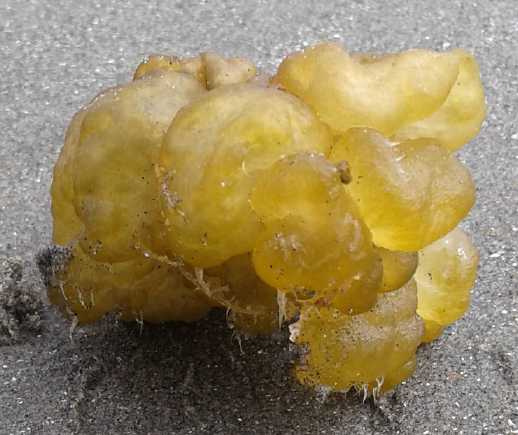 Some years ago
an oceanographic survey found a "sponge reef" in Hecate Strait.
Something different than a "coral reef", in water too cold for corals.
This caused quite a stir in paleontology as it had been thought that
sponge reefs had been extinct since the days of the dinosaurs.
Some years ago
an oceanographic survey found a "sponge reef" in Hecate Strait.
Something different than a "coral reef", in water too cold for corals.
This caused quite a stir in paleontology as it had been thought that
sponge reefs had been extinct since the days of the dinosaurs.
Now I'm going on memory, but it seems to me the sponges in
question were called "crystal sponges". These things wash up on the
beach here during the summer. I suspect this is the creature here. Is
this what all the fuss is about?
Moles and hydrocortosone cream: Update
Some months ago I mentioned the idea of putting something
on moles and other similar skin blemishes that would treat them as
injured skin
that needed to heal rather than as a foreign entity that needed to be
eradicated. (TE News #111, April-August 2017) I tried it out and said I
would write an update if I got
any results.
Attacking the blemish is what one thinks of first,
but it rarely works out well. (Usually it's best to leave them
alone, although this is not invariably true and it can occasionally
mean life or death to make the right choice. It's best to
consult a doctor if something on your skin is changing and you are
concerned.)
But I decided to try putting something on them to see if
some moles or other blemishes might be coaxed to heal. The only
substance I know of that helps to heal instead of
attacking is hydrocortosone cream. I very gradually shrank a cyst on my
arm since childhood from a considerable lump and irritant to almost
nothing with it.
It's still shrinking with application, but so far has refused to
entirely disappear.
At first I applied the cream every evening, but not
noticing any results, I soon dropped that to every 2nd (even numbered)
evening. I did
that for the many months it's been since I first wrote about it, and
wasn't seeing much change. Then a few weeks ago I stopped. At first I
didn't see any change, but then a few of them started getting dark
spots and crusty on the surface. Then I remembered that these had been
that way previously. The lightening and softening had been so gradual I
hadn't been
aware of it. Only a very few moles with a smoother texture had stayed
dark. So applying the cream had eliminated the dark
crusty spots and prevented them from reappearing as long as I was using
it. They stayed relatively soft and light in color. It's not a cure,
but I'm sure it's significant. It's at least a healthy and innocuous
general treatment that can be applied to moles where there hasn't been
much of one of any sort available that I've heard of.
I presently plan to keep it up one day a week, Saturday or
Sunday. I'll increase that if the crusty and dark spots don't go and
stay away.
I'll think of it as something that just needs to be done for better
health,
like brushing
and flossing your teeth.
I hope that some day someone will invent a cream (or
something) that
actually heals such things and makes them vanish. That would be a
factor in people starting to live 2 or 3 hundred years in the coming
decades and centuries. Today people already live substantially longer,
on average, than they did 70 or 80 years ago, when the percentage of
the population over age 65 or 70 was very small. (whether because of
improving living standards and medicine since then, or just because
everyone smoked tobacco back then...?) Go back just 300 (or maybe a
little farther) years and living to 50 was an accomplishment not shared
by the
majority. In principle the potential for cultural improvement goes up
with life span, as more people gain time to learn and understand what's
better and have opportunities to apply and share that knowledge before
they exit the planet. (And now we can share much better, via the
internet.)
Feeding the 9 Billion?
A news article asked how we were going to feed 9 billion
people "by 2050". I came up with two possible answers which may be seen
by some as impractical:
1) Start feeding them now. You'll have fed them all long before 2050.
2) Deposit food in a food bank. By 2050 everyone should be able to eat
off the accrued interest.
Well I might be more concerned if I thought there would
ever be that many people. Signs of a crash well before mid century are
all around us. 47% of Americans are now having trouble paying for food
and rent. Most will never own their own house, and most of those who do
have a huge mortgage on it - banks and investors have bought them all
with 'free money' - wealth transferred from citizens to the financial
'services' community mainly via unprecedented new money printing, which
will sooner or later cause hyperinflation. The whole middle east is in
turmoil. Venezuela has crashed. Brazil and Argentina are crashing.
China is in bad shape. More refugees than ever before in history are on
the move or stuck in refugee camps, and they are destabilizing Europe
too. The heat keeps rising so gradually people don't notice it. The
"news" doesn't cover it. And now the environment and the climate are
bringing natural disasters (some of them actually man caused, I'm sure)
into the picture and there are predictions for famine and devastating
epidemics. Food production today is adequate at the best of times, but
is being hit by climate change, and things beyond human control are
happening with increasing frequency and severity. Consider if for
example a volcano should darken the skies for a year or two as
occasionally happens, it would spark a major catastrophe in food
production.
We are surely on the eve of the gigantic collapse
predicted as the inevitable outcome of uncontrolled growth on a finite
planet ever since the earliest computer modeling in the 1960s. And the
more people there are, the lower everyones' quality of life. Most of
our problems have their root in overpopulation. If we were suddenly
down to 2 billion people (as we just might be by 2050), there would be
almost four times the resources to support each person as there are
today. Imagine the relief to the environment. Imagine how the cost of
housing would drop if the population was gradually shrinking instead of
gradually expanding. In a rapid drop in which homes are not destroyed
en masse too, there will quickly be no more homeless people. What is an
optimum population for this planet? Surely under half of what we have
today (ie, 3.5 billion) and probably closer to 3 billion, or even under
that.
It has been predicted that even a single year may come
when the "world as we know it" will be there at the start, but will no
longer exist after it. It will be incredibly transformed. The aware may
sense that year approaching... or not!
---
After the Thugs
When the thugs have come to rule the roost,
when psychopathy is the most rewarded trait,
And those in economic power, behind the scenes,
grasp control from the people the reigns of political power
to manipulate them for selfish ends,
and now resent attempts to address imbalances,
or to improve the static status quo,
When the rights and interests of the citizens take a back seat to
everything else,
and their attempts to participate in decision making are repeatedly
rejected
with indifference, or they are beaten by police,
When a few live beyond the reach of the laws imposed on everyone else,
Such a society is doomed.
And this becomes the best outcome,
because it would never be possible to start again
unless these covert kings were toppled from their hidden thrones,
with the tilted cards laid face up on the table and in the light for
all to see,
and the people exercise their democratic rights,
to fairly distribute new cards, change the games and level the tables,
in favor of the seven cosmic values of Social Sustainability
to sustain families and society, everyone equitably, for all future
time:
Life, Equality, Growth, and Quality of Life, all executed in
understanding Empathy, Compassion and Love for humanity and the world.
And with these
to create sustainable moralities anew in each progressing generation,
the planet and its peoples,
with an ever advancing populace and society, and a stable population,
headed toward light and life instead of away,
towards our cosmic evolutionary destiny of Universal Perfection,
even as the Father in Heaven,
the first source and center of infinity and reality,
is Perfect.
---
We know from the Bible that the world is only 6000 years
old. (um, where does it say that, again?) Therefore those early
Christians who
first postulated that the world is 6000 years old were wrong, since it
must have
been less than 5000 years old back when they did!
"in depth reports" for
each project are below. I hope they may be useful to anyone who wants
to get
into a similar project, to glean ideas for how something
might be done, as well as things that might have been tried or thought
of... and even of how not to do something - why it didn't
work or proved impractical. Sometimes they set out inventive thoughts
almost as they occur - and are the actual organization and elaboration
in
writing of
those thoughts. They are thus partly a diary and are not
extensively proof-read for literary perfection and consistency before
publication. I hope they add to the body of wisdom for other
researchers and developers to help them find more productive paths and
avoid potential pitfalls.
Other "Green" Electric Equipment Projects
Carmichael
Mill ("Bandsaw Alaska Mill")
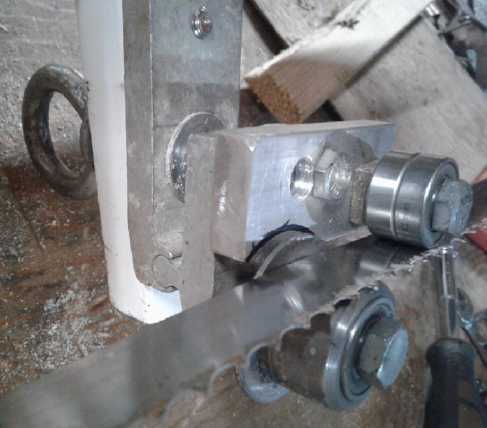
Band Guides - Adjustments & Cuts
After spending the whole month on one exciting (and mostly
successful) battery experiment after another, I finally mounted the
"railway wheel" band guide wheels on the saw on the evening of the 27th
.
 On the exit
side I did the simplest thing: I used the main wheel as the 'other'
guide wheel by not putting the new one exactly in line with it, so the
band went over it in a very slight arc. (Okay very slight.)
On the exit
side I did the simplest thing: I used the main wheel as the 'other'
guide wheel by not putting the new one exactly in line with it, so the
band went over it in a very slight arc. (Okay very slight.)
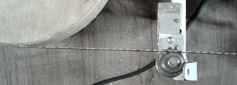
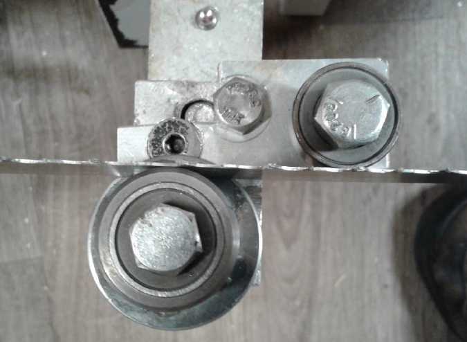 On the entry
side I figured that wasn't good enough and put in the offset wheels
design as planned in the last issue: The "railway" wheel in line with
the main wheels and the offset wheel pushing the band down a bit
against it, again the band making a slight arc over it. (When tension
was put on it it swiveled a bit and again the arc was very
slight.)
On the entry
side I figured that wasn't good enough and put in the offset wheels
design as planned in the last issue: The "railway" wheel in line with
the main wheels and the offset wheel pushing the band down a bit
against it, again the band making a slight arc over it. (When tension
was put on it it swiveled a bit and again the arc was very
slight.)
The attack angles to aim the blade up and down are again
both adjustable by the hinged assemblies with springs.
This brings up the idea of
possibly changing the design a bit: The main wheels could be any size,
eg, 9 inches, with the guide wheels lower and the band arched under
them, making it a "four wheel bandsaw". With the guide wheels lower
than the main wheels they can make extra cutting depth. On the minus
side, to change the cut width the band would have to be slackened off
and retensioned.
The next morning I tried cutting. I hadn't got the
positions set very well. There wasn't enough bend in the band on the
entry side, and if it decided to go up, it pulled away from the main
wheel entirely. That pretty much upset the applecart. The band would
then also pull completely away from tracking on the exit wheel - which
also didn't form enough of a bend in the band to be secure. After one
crappy board and starting in a couple of feet into another it started
raining, plus I had other things to do (band rehearsals).
But the fixes were in my mind. Both sides would have
accompanying top wheels, and they would both cause more bending of the
band so a good arc was stretched over each 'railway' wheel. Either
that, or I should set both guide wheels down lower per the potential
design change above. But if I did that, the guide wheel adjustment
springs were upside down. They would have to push up instead of down,
with a solid adjustment for pushing down, since they would then be
operating against the band's tension.
 On the 29th I
fixed up the entry side. I had been having problems from the start with
the threads being stripped in the adjustment hole. I had bashed the
thin end to squash the threaded hole down a bit more than once, but now
again to my surprise, the bolt just skipped threads when I tried to
tighten it beyond "easy". It occurred to me to make another threaded
hole in my add-on piece, and let the bolt come right through into that.
Using that hole as one support as well actually made it easier to make.
But once again by then it was getting dark. I didn't get to doing
anything with the exit side.
On the 29th I
fixed up the entry side. I had been having problems from the start with
the threads being stripped in the adjustment hole. I had bashed the
thin end to squash the threaded hole down a bit more than once, but now
again to my surprise, the bolt just skipped threads when I tried to
tighten it beyond "easy". It occurred to me to make another threaded
hole in my add-on piece, and let the bolt come right through into that.
Using that hole as one support as well actually made it easier to make.
But once again by then it was getting dark. I didn't get to doing
anything with the exit side.
The next evening (30th) I took the saw out and tried
cutting. For some reason it seemed the guide would adjust too far down
or even farther down. The spring was fully compressed. (maybe at the
top it was about centered.) And I couldn't understand why it seemed so
hard to push the saw, even while the cut seemed about right... and the
band didn't stop instantly when I released the switch. Finally I
realized that the rough cedar board had a lot more friction because it
was damp. There was nothing wrong with the cutting, it wasn't the
friction. I got a washer and inserted it so the whole adjustment
mechanism was aimed up a bit higher. It seemed I goofed on that because
when I went farther the cut was veering up. Then it seemed very hard to
get it to go level. Then I started cutting slower, and the cut started
going straight. I didn't think I was really pushing it before, but
slowing down definitely helped.
When the cut was veering up, the exit side wheel, being
just a single wheel, simply let it lose contact and go up. That was
actually useful to see when it wasn't going straight. This board didn't
have any of the side to side bow shape of many of this saw's cuts, from
poor adjustment. But then also I had considerably tightened the band,
which doubtless made a big difference.
I started thinking maybe my
neighbor was wrong about the band speed being too high. There's
probably a relationship between band speed and the speed you can push
the saw without it starting to veer off up or down. If the relationship
is as it seemed to be this day, it should go faster so you can cut
faster, instead.
Another possibility I though of for design change would be
to have the guide wheels fixed in position (if it's possible to align
them very exactly and alike), and have the 'skis' (or whatever part of
the saw rests on the board) adjust front to back, so the whole saw
angles up or down a bit until it's cutting straight. That would also be
the easiest and most obvious thing to adjust from an operator's point
of view.
Then I had a whole new inspiration that changed
everything...
Self Correcting Band Guides - Concept
Most people, including me, just copy what has been done
before. We "innovate" but within the existing basic framework. Only
occasionally do we manage to step back outside that box and see that
the box itself is the problem. Then we "invent".
Finally, on the night of the 30th, I thought that the cut
direction of all bandsaws - all the ones I've ever seen - has a positive
feedback loop in it: Once it starts veering off the line, the farther
the band strays from the intended cut line, the more it wants to veer
still farther off. Freehand in a shop, the operator can compensate by
moving the back of the board left or right as he feeds it. On a mill or
saw where the saw to board cutting angle is fixed, once it has veered
off the line far enough, the back of the band tries to stay on target,
while the front leads the way off target and the tilt or attack angle
of the band gets worse and worse. The board is ruined, and finally the
saw jams.
A negative feedback loop leads to stability. How
to get that? Instead of manual adjustments, the band angle needs to
adjust itself to straighten out the cut as it cuts.
What if it was made so the front of the guide wheels, at
the front of the band, was the pivot point and the back of the wheels
could be moved up and down, instead of the pivot point being behind the
band or at best in the middle with guide blocks? Instead of trying to
carefully fix the band aim as a solid constant, there should be some
way to make it so that if the cut was going above the set line, the
back of the band would be pushed upward further than the front was up,
and if it was below, the back would be pushed downward more than the
front. Thus instead of veering off and going off worse and worse the
more it veered, the band's attack angle would adjust to compensate.
Instead of being a finicky adjustment, the cut direction would be self
correcting. In fact, if the pivot point was a little in front of the
band, this correction effect should be attained smoothly and
automatically with little deviation from the path.
The one manual adjustment point would be to set the
springs to hold the back up so the blade enters the wood level at the
beginning of the cut.
Here, I think, is a real breakthrough in bandsaw mill
design. I could see this one being the first handheld band mill that
will be commercially successful, and wanted by everyone. The serious
objection to all band mills, that the cuts sometimes veer off, the one
that keeps people looking for a better mill even after they have a band
mill of some sort, would be eliminated. In retrospect it seems like a
stupidly simple idea - as so many good ideas do in retrospect - yet as
far as I've discovered no one ever seems to have made such a guide
system for a bandsaw or bandmill before. (This will be fantastic!
Now... how to build it?)
On July 2nd I went and looked at the Woodmizer mill again.
I remembered some unusual and elaborate things about how it held the
guide wheels. Could I have possibly come up with something that already
exists? But no, the elaborate things were to hold the wheels as stiffly
and as precisely as possible, not to make them self correcting. If
Woodmizer, the premium maker of bandsaw mills, hadn't figured it out,
no one had.
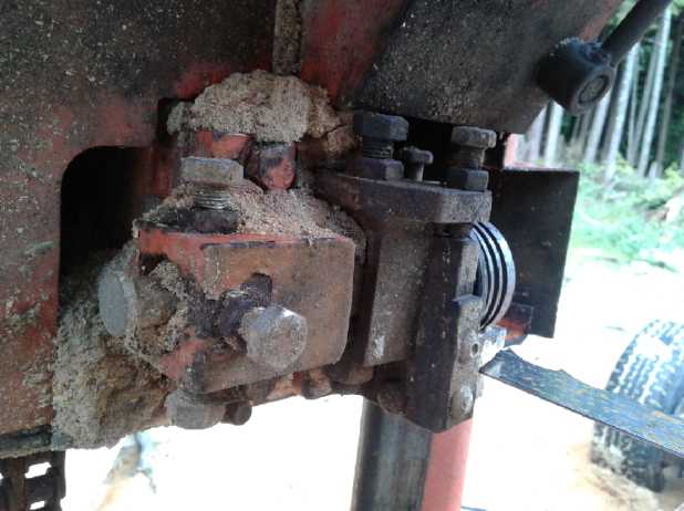
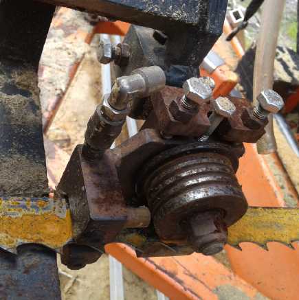
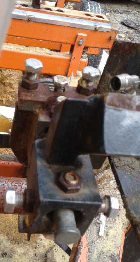 Woodmizer band guide wheels and mountings.
Note the elaborate means provided for fine up-down and left-right
adjustments,
and for keeping the adjustments solidly in exact place once made...
nothing for self-correction of the cutting path.
Proposed New Electrical Standards:
A Low Voltage Standard (36/38
volts DC) and Standard Connectors
I got no feedback on my
ideas from last month. I don't suppose people (even most TE News
readers) had or have given such an area much thought. A new idea that
occurs to me for the 38 (AKA "36") volt standard is to make not only
plugs, sockets, wall plates and other connection components, but to
also make (or more likely have others make) 36 volt appliances sold
with these connectors - especially LED light fixtures and lamps. Such
products would kick-start that voltage as a new standard. They would be
marketed to solar and off-grid equipment suppliers and distributors.
(BTW I vaguely remember some new car a few years ago that
was going to use 36 volts for the lights and all. (At least, I think it
was 36... lights, starter, alternator, fans, stereo...?) I wonder if
that was ever produced, and what 36 volt equipment might have become
available? Or did they change their minds because of the lack of
available 36 volt equipment?)
Something I didn't think to remark on in the last issue:
When I ran the coffee maker from a 36 VDC to 120 VAC inverter, I had to
wire the inverter to the car batteries. If the coffee maker was 1500
watts and thus took 12.5 amps at 120 volts, it must have drawn about
39.5 amps at 38 volts. Thus a 40 amp (or maybe it should be 50 amp?)
HAT standard socket in the car and matching plug on the inverter would
have made for a simple plug-in solution - no wrenches and no chance of
miswiring or shorting something out, which often destroys inverters
among other potential problems.
On further consideration, it might be worth making the
40/50 amp sockets all "click-latch" type. Sudden loss of power from the
supply coming unplugged is another cause of delicate equipment failure,
and latching plugs to sockets should eliminate that. For simple
equipment where it might be a nuisance the plug need not have the
latch. (Which gets me to the thought that I haven't defined the
latching spec. For now see the CAT standard click-lock plug and socket
designs on thingiverse.com .)
Another thing I might remark on is that a 12 VDC to 120
VAC inverter would have drawn 125 amps from the 12 volts. That's pretty
serious current needing very heavy wires, and a 1 volt line drop is 8%
power loss. 38 volts DC is a much better voltage for things needing any
significant amount of power, yet it still doesn't need a big bank of
batteries to attain and no one is in serious electrical danger.
Rechargeable
Battery Making
with oxalate electrolyte:
* Nickel-Zinc *
* Manganese-Zinc *
* Lead-Zinc *
I consider that after 10 years I finally achieved the main objective of
the whole "better battery" project when I got a nickel-zinc cell to
work almost at the start of June.
However, that particular chemistry seems rather hard to
make at home, and I thought it would be nice to find some means for
home battery making, or at least for making them with a minimal
production setup. So I continued experimenting. Making good electrodes
has always seemed to be a difficult and obscure problem beyond the
chemistry, and I started coming to grips with that in June.
It's the Electrolyte
Perhaps the most exciting invention has been the
electrolyte rather than any particular electrode or electrode
developments. Realizing that an everlasting zinc
negative electrode is enabled by this electrolyte is certainly the
second
most prominent development. Then three fine possibilities appear for
positive electrodes: nickel, manganese, and lead.
The voltage of the nickel, or mixed valence nickel
manganates, at pH 12 instead of 14 is such that it appears special
techniques must
be employed to use it, but the cells have the highest voltage (~1.8v)
and energy. I may experiment further, but it looks right now as if it's
best to leave this to commercial battery
makers.
Manganese (1.4-1.5v cells) is simpler. Much has been made
of
manganese forming permanganate and dissolving, limiting cycle life, but
at pH 12 there's a .45 volt spread between MnO2 (manganese dioxide) and
KMnO4 (potassium permanganate), and I think it's just
a matter of strictly regulating the charge voltage to stay about 1/4
volt below the permanganate forming threshold. An everlasting
manganese-zinc battery would be very exciting because it's so low cost
and
such high energy - substantially higher by weight than lithiums. And if
there was ever a battery that might be made from scratch at home, this
is probably it. I made one that, while not perfect, worked well before
the end of the month.
Lead (1.6v) is also simpler. If the permanganate turns out
to be a serious issue in spite of the various improvements, everlasting
lead-zinc could be a great alternative. The easy way to get lead
dioxide plus electrodes is to take them from a lead-acid battery, but
it should be a new battery that has never been filled with acid to
avoid sulfate contamination, or somehow the sulfates must be completely
removed. The energy density depends on how much
energy can be coaxed out of the lead electrode at good voltage compared
with its apparently much higher theoretical value. I also made more
than one such lead-zinc test cell that worked with lead oxide
electrodes taken from a new, unfilled lead-acid battery.
While I note that a metallic manganese negative electrode,
enabled by trace
additives (successfully made - see previous issues from 2011-2013) at
-1.5v has a higher voltage than zinc
at -1.2v and with a nickel plus makes cells of 2.4-2.6 volts, the zinc
is
easier to use and apparently yields a higher percentage of its
theoretical amp-hour capacity.
Zinc!
Almost since batteries were invented, a cell with a zinc negative
electrode that doesn't degrade has been a "holy grail" of battery
making. Zinc has soluble ions at any acid pH and also at the alkaline
battery pH of 14. There is a range of pH from 7 to 13.5 where zinc
doesn't inherently form a soluble ion, but in neutral salt electrolytes
such as the ammonium chloride of "good old" single use manganese-zinc
(AKA "carbon-zinc") dry cells, zinc chloride is soluble, so the zinc
still
dissolves. Acid has also been tried. In all cases the zinc electrode
deteriorates over time and
cycling, giving batteries with a zinc electrode a notoriously short
cycle life. Many have tried with no better than marginal success
to tame zinc for battery negative electrodes.
On the same day I put out the last newsletter I was also
looking at some Pourbaix diagrams. I looked at zinc and suddenly
realized I had done it, almost by accident. My electrolyte was about pH
12, and the diagram showed zinc didn't form the soluble zincate
ion below about pH 13.5. Furthermore, unlike zinc chloride, zinc
oxalate isn't soluble. The three forms the zinc might take then,
metallic zinc, zinc oxide and zinc oxalate are all solid, so the
electrode won't degrade. It would work just as well as nickel and has a
much higher voltage (-1.2 V versus -.5 V).
(This reminds me of creating my "Supercorder" alto
recorder. It could just as well have been created in the 19th century
when so many other woodwind instruments and their key systems were
being much improved, but nobody made a truly practical modern recorder
until I did in 2003-2006. Likewise, someone could have made this
electrolyte even 150 years ago (oxalate salts were known before
batteries), and we'd have had cheap rechargeable batteries ever since.
But nobody did. The grail was left to me in 2018!)
Positive Electrode Compaction
I was right onto this at the turn of the month and I kept
working on it and thinking about it. By the evening of June 2nd I had
realized that the only way I could get the extreme pressure that seemed
to be required
to condense the loose powder into an electrode "briquette" was to
hammer
heavily on a very small surface area. Say, the thickness of the
electrode instead of the width, and only a thin strip instead of a wide
electrode. Maybe 3 mm by 10 mm. It could be any depth because a little
powder would be poured in at a time.
Next morning I looked at an "edge loading" compactor I'd
made 3 or 4 years ago to make electrodes for my 3D printed
nickel-manganese cells, and started remembering details of its
operation. Its compaction using the hydraulic press had been
insufficient too, but far superior to most of my other results. The
cells at
least had something like an amp-hour (out of 5 or 6 expected) instead
of milliamp-hours, and could charge at and put out at least somewhat
respectable current.
I would fill it with powder and then compress it 5 or 6
times before it was filled. Each layer was thinner than the one below
since it fit less powder each time as it filled. And the resistance
measured much lower at the top of each layer than at the bottom, so the
material wasn't sliding along the sides of the compactor very well.
I conceived that the required compactor would have to be
made of
something tougher than mild steel, which was bound to bend and bulge
out, and sure enough this one was tougher 3/8" stainless steel. But it
had to be narrower to get the pressure, eg, 1 cm wide instead of 6.
Then I thought, what if I put in 6 narrow "plungers" to pound on, each
1 cm wide? If pounding on each one didn't make its neighbors bounce out
and just shift the powder back and forth, they could be pounded on
individually in sequence, more gradually doing the whole width.
Suddenly the whole plan started seeming more possible, at least for
test electrodes.
In practice I ended up cutting up an old file that was the
right thickness and using the three pieces as a bottom for the
compactor, a filler for one side, both filling in space to make it a
much smaller electrode, and the handle as the plunger to pound on. The
handle was wider than I had thought of, but it could do one side or the
other and it could be angled to hit harder on one corner than the other.
I also thought about different mixtures for this electrode
and whether some might need less pressure to compact than others. First
I measured out 30 grams of the mix I had been using (15 cc?) and added
3 cc of Veegum, then I weighed 30 grams of a nickel-manganese mix that
I found in the cupboard. This one was much less dense and filled 24 cc,
plus again 3 cc Veegum. I didn't use it. (The description of Veegum is
in TE News #21...
Just ignore the parts of the project where I didn't know what I was
doing back then!)
I compacted the second substance first, adding a bit at a
time and a bit of the dishsoap here and there, and pounding it with a
20 ounce hammer until it felt like I was simply pounding on metal. It
made a nice "briquette". Resistance from the surface to the back was
around 70 kilohms. That's pretty high, but two orders of magnitude
better than 7 megohms. I only squeezed in about 60% of the powder or
maybe 18 grams to fill the space, about 4 x 40 x 40 mm. I did the
second one from the denser original mix and put in the whole 30 grams
to get the same size. I pounded pretty hard and was hoping for better
results, but it was again ones of megohms. I fear something would bust
or bend if I used the 6 pound maul. Then the other briquette started
giving very similar figures. Then this one gave the lower values.
Perhaps there's some ionic conductivity going on. Simply reversing the
test leads always gave widely different results, so one couldn't just
say "It's X ohms" as a repeatable figure. All very frustrating!
18 grams in (.4 * 4 * 4)cm = 2.8 g/cc
30 grams in (.4 * 4 * 4)cm = 4.6 g/cc
From these figures it can be seen that if the two powders give the same
energy per gram, the second one will make for a more compact battery,
with savings in space and case material. IIRC, both of them are higher
than I remember seeing for typical nickel hydroxide electrodes: 1.8
g/cc (or was it 2.2?).
Perhaps I should start experimenting with mixtures for
best performance, which would really mean lowest resistance with the
pressure I can attain.
Glue & Jell
Concurrently with the chemical and compaction trials, I
again started putting "stuff" into the electrodes to help hold them
together as thickeners, binding agents and gels. Pretty much the same
ones I was using years ago. With the successful
electrodes to compare with I could tell if the additive(s) were causing
a problem. They helped. As I proposed and later research also
discovered, jelled electrodes can last forever. (I wonder if they got
the idea to try it from Turquoise Energy News?)
(
See TE News #99:
http://www.theweathernetwork.com/news/articles/scientists-accidentally-make-batteries-that-last-a-lifetime/66934/
-- 200000 cycles with no deterioration, to the surprise of the
researchers.
)
The first was something called "Veegum", a powdered smectite
(bentonite) clay: Magnesium-Aluminum Silicate. I put in by volume maybe
15-20% Veegum into the electrode. It thickens and adds viscosity. The
powder is very light, so it wasn't much by weight. The next was
Sunlight original formula dishsoap as a "glue" or "gel" with its
organic
sulfate and sulfonate compounds. (I mentioned it from as early as TE
News #6 in 2008.) I just added drops of this as I compacted electrodes.
The clay seemed to help hold them together without
wrecking the electrodes chemically. I used both of these in
both the plus and minus electrodes. I considered using "CMC gum" as
noted by other battery makers, but I didn't add any. I note that in the
literature on "Veegum" there are several varieties, and "Veegum Plus"
has CMC gum as an ingredient, probably better dispersed in the clay
than by adding it separately.
Zinc !
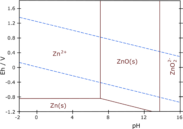
Now I stared at zinc's very simple diagram. It showed no
soluble states
between pH 7 or so to over 13. When I had looked before I was
using
potassium chloride electrolyte which zinc could dissolve in. Now I was
using potassium oxalate, and zinc oxalate is insoluble. (That most
potential battery elements including zinc were insoluble as oxalates
was one of my original reasons for noticing oxalate, going through the
"solubility table" in Wikipedia. But I was thinking of oxalic acid at
the time.)
Many have tried to 'tame' zinc for rechargeable cells
without more than partial success. Some nickel-zinc "AA" alkaline cells
are (or recently were) available which claim they have 500 cycle
capacity (I suspect only
under ideal conditions). I finally concluded the researchers were
wasting their
time, and looked for other metals. But every reported attempt I've
looked at - several patents or studies - was in pH 14
hydroxide electrolyte except one. That one, in acid, had zinc
intentionally dissolve
as the cell discharged, and reform as it recharged. It still grew
dendrites.
Here is something quite different. As with nickel, I
don't think anyone else has tried oxalate or "mid alkaline pH" other
than chloride, with zinc before. Apparently zinc/zinc oxide/zinc
oxalate would stay solid at all times up to over pH 13. And higher
voltage negative
electrodes might be better in ethaline DES than in water, too.
Nickel-zinc-oxalate cells would give
around 1.8 volts. Whatever nickel's
extra amp-hours (as a negative electrode), it wasn't likely to match
the energy of zinc with this
high voltage when zinc is also a good energetic electrode. Nickel-zinc
would take
fewer cells to reach a desired voltage: probably 7 cells for 12 volts
instead of 8 or 9 or 10.
As an added benefit zinc is cheap, much cheaper than
nickel, which will mean, in principle, pretty cheap batteries.
So I started pondering: Would zinc insist on growing
dendrites and
deteriorate at pH
12 to 13 in oxalate? Or would it really last forever as this Pourbaix
diagram indicates it
should?
Since my cells are already just right in every other
respect I decided it would
definitely be worth an experiment or two with zinc powder instead of
nickel powder.
I decided to make a square cell just the size of the above
electrodes. I finally recalled that the positive electrodes, however
well they are compacted, swell up once wetted (at least in water - I'm
not sure about ethaline DES. Either that or it's with charging and
discharging.) In a cell the right size, they'd have little room to
swell. I used the 30 gram electrode.
The zinc electrode turned out to be just 20 grams, about
the same size because it was compacted in the same compactor, but I
nipped a bit off the edges so it would fit inside the paper basket, so
it was about 37 x 38 mm. (theoretically 20 g * 820 AH/g = 16.4
amp-hours... in such a tiny, lightweight cell? How well will that
actually be utilized? Prospects seemed good for high utilization
because the zinc powder, unlike most metal powders, seems to be of
"nano" size, providing potentially the highest surface area.) After
working with zinc powder I knew exactly how they gave the tin woodsman
his color in the Wizard of Oz movie. (Did you know the entire plot of
the book was a metaphor for the whole twisted financial system? "Follow
the Yellow Brick Road to the Emerald City"... does that not sound like
the promise dangled in front of everyone? The "silver slippers", silver
having been until recently the money of the common innocent person
(Dorothy), turned into "ruby slippers" in the movie. It didn't matter
because nobody knew the underlying plot anyway. After this book
families demanded more kids fairy tales about Oz, and the author had
found his calling. They are however apparently not as memorable as the
first. I only read one other, "The Land of Oz". It was okay but the
plot wasn't the equal of "Wizard of Oz".)
Making a New Cell
I went to put the new cell together and did everything wrong, out of
sequence. As a result, the plus electrode was pretty much broken up
into chunks and powder.
Here's how it ought to have been done:
1. Torch the positive electrode with a strong propane torch for
about 10 seconds to sinter the particles together a little better. (I
finally remembered about this. After so long doing no battery work I
had forgotten on the last cells.)
2. Make the case but leave one side and the top (front) face off.
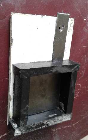
3. Cut the graphite current collector
piece and paint it with the
osmium doped acetal ester. When it's dry, put it in. Put a small bolt
and washer through to the plastic support before the tab gets broken
off.
4. Slide the plus electrode into the case - easier with one side off
the case -
then glue the last side on with methylene chloride (or plumbing ABS
solvent glue).
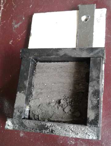
5. Make a [watercolor, thick] paper
'basket' to cover the bottom
electrode and go up the sides so the electrodes won't short against
each other.
6. Put the zinc minus electrode in the paper basket.
7. Cut a piece of nickel mesh to cover
the back of the zinc electrode
for a current collector. (Unless the zinc electrode is totally
discharged to zinc oxide, the nickel will remain in metallic form.) I
made one with 3 folds and a fourth bit.
8. Stick a piece of cupro-nickel sheet
in for a tab. I tucked it under
the last fold in the mesh for better contact.
9. Fill in any remaining empty space in the cell. I used bits of
cupro-nickel sheet.
10. Take out enough bits to expose the
mesh and add a little calcium
hydroxide powder. Add some DES with potassium oxalate dissolved in it.
(Put the bits back in.)
11. Put the top/front face on. (I just held it shut with a C-clamp so I
could open it again. Later I put heat glue around the edges and the
terminals.)
Ready to charge!
After I torched the plus
electrode I couldn't get any
resistance readings. It was off the scale. I hoped it would improve
with charging and discharging. When I put the cell on charge, it only
took .3 mA at 2.2 volts. It was going to take forever (approximately)
to charge up to a few amp-hours!
But maybe if the plus electrode has no room to bloat out,
its conductivity will go up over time instead of peaking and then going
down? Then I discovered the filler pieces sitting on the counter.
somehow I hadn't put them back in when I put a C-clamp on to clamp the
front cover closed. So it was pretty loose inside until I fixed it.
After a while, after that, it was drawing 2.3 mA.
(forever / 8) Then I got out the heat glue and sealed it up better
around
the terminal tabs and the clamped-on front. While a nickel negative
charging to lower than the voltage of hydride wouldn't react to oxygen
entering the cell, zinc would certainly self discharge.
How ironic that
after a little demo with nickel-zinc in oxalic acid a decade ago and
then casting it aside, I now end up doing nickel-zinc in oxalate. I
little knew what I almost had, how close I was.
HOMEMADE!
Manganese-Zinc
Batteries
Many readers will recognize this chemistry - the most
familiar of all, so-called "carbon-zinc". I thought about how to make a
manganese-zinc cell because the reaction voltage of manganese is lower
than nickel, so the ethaline DES shouldn't be required, and graphite or
conductive carbon black can be used to make the electrode conductive.
That would solve the biggest problem for making them at home.
We already know MnZn works in water both at neutral pH
(standard dry cell) and at pH 14 (alkaline dry cell). And onto that
topic... there are already MnZn cells everywhere! Is it necessary to
make your own at all?
So since they already exist and much is known about
them... How would MnZn be for performance? Wikipedia says MnZn alkaline
"D" cells have 12 to 18 amp-hours at a nominal 1.5 volts. (Capacity
decreases as current rate increases. A cell might have 18 amp-hours if
discharged at 50 mA and only 12 amp-hours at 500 mA.) The old alkaline
D cells I tried put out 7 to 8 amps short circuit current. Admittedly
it
would take a lot of cells in parallel to get 300 amps - about 60 or 70
of them. It takes 8 cells to make 12 volts, so 24 for the 36 volt car:
around 1560 cells to run the car. 65 cells * 12 AH/cell * 36v = 28080
WH - quite a respectable EV battery. 147 g/cell * 1560 = 229 Kg = 506
pounds. Now we compare that with the lithiums in the Sprint: 38 V * 300
AH = 11400 WH, at 260 pounds. To get the 28080 WH they would weigh
more. (640 pounds)
Apparently even manganese-zinc "D" cells are better than
lithiums - if they can put out the required current and if they can be
recharged reliably. If they were made differently (eg, rolled-up
electrodes like Ni-MH, Ni-Cd - or flat plates) they would put out
higher current and fewer would be
required to get the 300 amps. (Nickel-zinc is somewhat higher voltage
and so still better.)
Oops, "Charged" refers to MnO2 state area and
"Discharged" to
the Mn2O3 region. These words do not refer to the lines with
arrows that they are immediately above, which represent the
"overcharge" and "charge" electrode voltages.
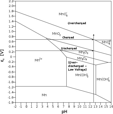 The one caveat to potentially making rechargeable cells with manganese
positive electrodes is that if the charge voltage is a little too high,
the manganese dioxide turns into soluble permanganate ion (MnO4-),
which degrades the electrode. If it can be charged slowly and kept
under that voltage, how long might it last? We don't really know,
because it's always been used with zinc electrodes, and even charging
slowly the zinc electrode degrades so the cell doesn't last.
The one caveat to potentially making rechargeable cells with manganese
positive electrodes is that if the charge voltage is a little too high,
the manganese dioxide turns into soluble permanganate ion (MnO4-),
which degrades the electrode. If it can be charged slowly and kept
under that voltage, how long might it last? We don't really know,
because it's always been used with zinc electrodes, and even charging
slowly the zinc electrode degrades so the cell doesn't last.
So we're in uncharted territory here, but it appears that
using a less alkaline pH also prevents soluble Mn(OH)3- ion from
forming even if the cell is "overdischarged". So it just might last a
long time as long as the rather exact charging voltage condition is
always met. (With jelled electrodes it just might last forever, again
if charged exactly each time.)
An interesting aspect of "overdischarge" with manganese is
that if there's enough zinc, the cell will continue working well
putting out about 1.1 volts while the Mn2O3 converts to Mn3O4, and then
at about .9 volts as it goes to Mn(OH)2. It has as many amp-hours in
these two states together as it has at the full 1.5 volts, so double
amp-hours but at ever decreasing voltages.
From the Pourbaix diagram we see that at pH 12.7 the
manganese electrode needs to hit about .25 volts in order to charge
back to MnO2. But if it gets above about .7 volts, soluble ion MnO4-
(makes the electrolyte purple) is created.
Combining with the -1.2 volts of the zinc (Pourbaix
diagram in article above this one), we need to charge at somewhere over
1.45 volts to charge at all, but under 1.9 volts to avoid forming
permanganate. If we charge the cell at say 1.7 volts, in theory it will
last a long time. If it doesn't we could try 1.6 volts with a longer
charge. If 1.7 seems flawless, 1.8 could be tried but it would be more
likely to cause eventual trouble. 1.9 volts would be too much and would
cause deterioration.
In charging (eg) a 12 volt battery (of, say, 8 cells, 8 *
1.5 = 12.0; charge at 8 * 1.7 = 13.6 volts) one will have to be careful
that all the cells in series are at the same state of charge. One can't
have (eg) two cells at 1.6 volts and another forming permanganate at
1.9. It may or may not be necessary to have some sort of BMS that
bleeds off any excess above 1.8 volts or even 1.7. But I'm getting into
too much supposition for an idea that hasn't been tried yet.
Once I thought about using
MnZn, I thought about just using already made dry cells and changing
the electrolyte from chloride or hydroxide to oxalate. That simple step
might make them rechargeable.
The alkaline version - the whole existing battery - would
be perfect except that the can, which is the plus electrode current
collector, would probably oxidize away. Unless the oxalate formed a
surface layer that protected the rest underneath, as happens with
aluminum and titanium oxides. It was worth a try. But how to get into
the cell to change the electrolyte, without wrecking it? (Probably take
the bottom off of it.)
In the non-alkaline version, the standard dry cell, the
plus electrode goes to a carbon rod in the middle. That would work
great! It would be perfect except for the zinc - the outside can. It's
just a piece of sheet metal with little surface area. In the chloride
electrolyte it works by dissolving and continually exposing a fresh
layer during discharge. (until the zinc has a hole in it and the
electrolyte leaks out of the cell all over the inside of your device.)
So to use a 'standard' dry cell, we would want to peel off
the zinc outer can (eg, needlenose pliers). Put some cardboard or thick
paper over any breaks in the separator paper and then spread some zinc
powder around it. The less damage done to the inside the better. Then
tape the outer can (or something else?) back on over the powder with
plastic tape. The zinc outer can is sometimes an inner layer surrounded
by a steel outer can. (Accept only the cheapest cells, ones without the
steel!)
With either type, once it's open, immerse it in pure water
to dissolve out the chloride or hydroxide electrolyte. (Be especially
careful with the caustic hydroxide in the alkalines. Wash any off your
skin immediately and wear safety glasses. DO NOT get any in your eyes.)
After a while drain it/them on something to blot up the water, and
change the water in the tray to further dilute the electrolyte, at
least three times over several hours.
 I decided to
try the regular dry cells first. I didn't
find any "D" cells in my junk, so I broke open an old square 6 V
lantern battery with four "F" cells, a little taller than "D". The
outer zinc in these particular cells had completely corroded away and
fell off in
flakes when disturbed. That was perfect! On closer examination, much of
the separator paper was gone. But the inner plus electrodes were there
complete with carbon rod current collector. I had ready made "half
cells"!
I decided to
try the regular dry cells first. I didn't
find any "D" cells in my junk, so I broke open an old square 6 V
lantern battery with four "F" cells, a little taller than "D". The
outer zinc in these particular cells had completely corroded away and
fell off in
flakes when disturbed. That was perfect! On closer examination, much of
the separator paper was gone. But the inner plus electrodes were there
complete with carbon rod current collector. I had ready made "half
cells"!
 Then I went
for an alkaline "Duracell" "D" cell. I peeled
off the outer plastic around the bottom. This exposed a cardboard(?)
separator and the bottom metal cover. I stuck in a knife and pried, and
the cover started coming out, revealing the rod of zinc powder/paste. I
started thinking it might be really hard to get it back in once it was
out, or even very far out, and suddenly remembered that I only had to
get the cell open a bit. I put it in pure water to dilute out the KOH
(potassium hydroxide) electrolyte, however quickly or slowly that
happened. I tried an "Eveready" cell. The bottom cover was visible but
recessed and would have been harder to get open. A second "Duracell"
was different from the first with a smaller metal piece on the bottom
so the cardboard was exposed around it once the plastic was removed,
but it came open nicely too. Several "Evereadys" all looked the same.
Soon I had 4 "D" Duracells cracked open in the water along with the
four "F" manganese electrodes. If the alkaline cells worked, all one
would have to do was collect them from recycling bins to make
rechargeable batteries easily and almost for free.
Then I went
for an alkaline "Duracell" "D" cell. I peeled
off the outer plastic around the bottom. This exposed a cardboard(?)
separator and the bottom metal cover. I stuck in a knife and pried, and
the cover started coming out, revealing the rod of zinc powder/paste. I
started thinking it might be really hard to get it back in once it was
out, or even very far out, and suddenly remembered that I only had to
get the cell open a bit. I put it in pure water to dilute out the KOH
(potassium hydroxide) electrolyte, however quickly or slowly that
happened. I tried an "Eveready" cell. The bottom cover was visible but
recessed and would have been harder to get open. A second "Duracell"
was different from the first with a smaller metal piece on the bottom
so the cardboard was exposed around it once the plastic was removed,
but it came open nicely too. Several "Evereadys" all looked the same.
Soon I had 4 "D" Duracells cracked open in the water along with the
four "F" manganese electrodes. If the alkaline cells worked, all one
would have to do was collect them from recycling bins to make
rechargeable batteries easily and almost for free.
The voltage read a bit over 1.5 volts. These discarded
batteries put out about 7 or 8 amps. Not huge, but better than anything
I had made! Let's see... I just needed 8 for 12 volts. How many were in
the bag? 7. That figures! I tried to get an "Eveready" open with a
chisel and hammer, but even once I got the chisel under it wouldn't
come up. I finally ripped the bottom apart with the chisel to get it
off. Even then I still wasn't sure I was into the cell because there
was another metal bottom inside. It wasn't connected to anything and
only the little brass center pin was the negative terminal. (Later I
pried a Duracell farther open and found it also had another metal piece
inside blocking access to the bottom.)
Lead-Zinc Batteries
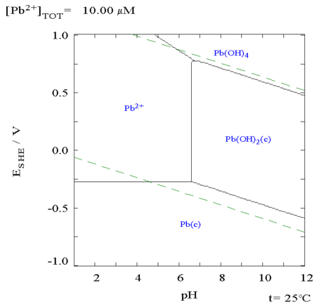 Another
interesting possibility occurred to me. Lead hydroxide in both
oxidations (Pb(OH)2 & Pb(OH)4) is insoluble and so is lead oxalate
(PbC2O4). A Lead electrode would probably last for ages in 'mild'
alkali oxalate. (Even more valuable if manganese proves not to work
very well in spite of the better electrolyte and with careful charge
voltage control.)
Another
interesting possibility occurred to me. Lead hydroxide in both
oxidations (Pb(OH)2 & Pb(OH)4) is insoluble and so is lead oxalate
(PbC2O4). A Lead electrode would probably last for ages in 'mild'
alkali oxalate. (Even more valuable if manganese proves not to work
very well in spite of the better electrolyte and with careful charge
voltage control.)
The voltage of about +.49 volts at pH 12 is virtually the
same as nickel at pH 14, and higher than manganese dioxide's +.25 volts
at pH 12.
Mn-Zn: +.25 - -1.2 = 1.45 volts
Pb-Zn: +.49 - -1.2 = 1.69 volts (Hmm, not bad at all!)
To make lead-zinc cells, one would open a lead-acid battery, dilute out
the acid, and collect the positive plates, discarding the negative
ones. (Presumably they wouldn't work very well if charged backward to
become positives? Then again...)
Make zinc negative electrodes. Reassemble the battery with
them instead of the lead negatives. If there's a bunch of space under
the electrodes, fill it in with something inert like plastic so you
don't need so much electrolyte.
Presumably the battery will be lighter. Zinc is a lighter
element (65.4) so it will take less of it to match the number of atoms
in the Pb (207.2) electrode. The voltage per cell is less so instead of
12 volts for 6 cells it'll be 10.14 volts. 7 cells would make 11.83
volts - close enough? (But maybe not very convenient for arranging or
packaging - and not for using a regular Pb-Pb battery charger.)
12 volts - with _?_ cells
-------------------------
Lithium/? - 4 (12.8v)
Ni-Mn/OxDES - 5 (12.5?) [Ox=the new oxalate/lime electrolyte. DES = in
ethaline DES instead of water.]
Pb-Pb/H2SO4 - 6
Ni-Zn/OxDES - 7 (12.6v?)
Pb-Zn/Ox - 7 (11.8v?)
Mn-Zn/Ox - 8 (12.5v?)
Ni-Ni/OxDES - 10
Ni-MH/KOH - 10
Ni-Cd/KOH - 10
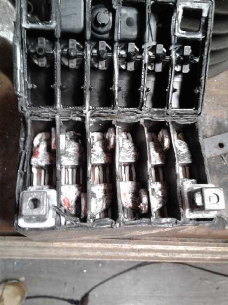 I decided this
would be worth a try. But at least for the
first try, I would get a new battery that hasn't been filled with acid
yet. It will be safer to cut open and the electrodes won't be
contaminated with sulfate, which zinc dissolves in. There are several
electrode plates to be made, and it would all be a waste of time if
they decayed because of that.
I decided this
would be worth a try. But at least for the
first try, I would get a new battery that hasn't been filled with acid
yet. It will be safer to cut open and the electrodes won't be
contaminated with sulfate, which zinc dissolves in. There are several
electrode plates to be made, and it would all be a waste of time if
they decayed because of that.
On the 12th I ended up buying a very small motorcycle
battery because those were the only ones around that weren't pre-filled
with acid. It weighed about 1670 grams (empty), or 278 g/cell.
I broke the case open just under the lid with a hammer and
chisel. The works stayed with the case rather than with the lid. That
was because the lead terminals were punched (melted?) together through
small holes in the walls between cells. Hitting the terminals with a
chisel broke the
connections and I pried a cell out.
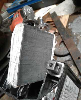 The 2 plus
plates were about 2.7 mm thick and
together
weighed 125 grams. The 3 minuses were 1.65 mm and weighed 122 grams.
The
pluses were 58.5 mm x 62.5 mm. The minuses were 56.5 x 62.5. The
fibreglass mats were folded over the plus plates to cover both sides.
There were thus 4 interface faces, totaling about (57.5 mm * 62.5 mm) *
4 = 144 square centimeters.
The 2 plus
plates were about 2.7 mm thick and
together
weighed 125 grams. The 3 minuses were 1.65 mm and weighed 122 grams.
The
pluses were 58.5 mm x 62.5 mm. The minuses were 56.5 x 62.5. The
fibreglass mats were folded over the plus plates to cover both sides.
There were thus 4 interface faces, totaling about (57.5 mm * 62.5 mm) *
4 = 144 square centimeters.
Lead dioxide-Lead [lead
acid] cell.
The brown ones are the lead oxide "+" electrodes
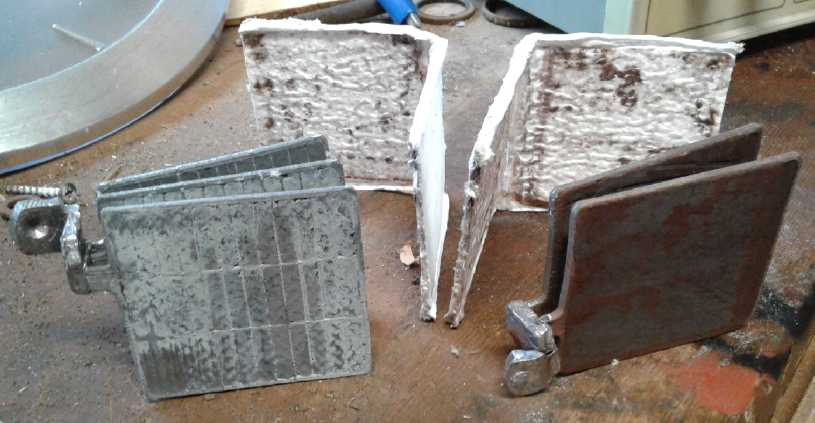
Some calculations, with
much speculation: It fits that
both electrode sets were similar weight because both sides move two
electrons per reaction, and the lead is way heavier than the oxygen. If
they put out, say, 200 mA per square cm with
zinc negatives, that would be 28 amps.
It was probably under about 4 amp-hours(?) (@ 12 V = 48
watt-hours; a whopping 48/1.670 Kg = 29 WH/Kg), holding about the
energy of two alkaline "D" cells (15 amp-hours @ 1.5 V = 22.5
watt-hours;
*2=45 WH; 45/294 g = 153 WH/Kg). (Typical of lead-acids, it didn't
actually
say. But it said "Fast charge at .8 amps for 3 hours"... or "Slow
charge at .4 amps for 5 to 10 hours" - somewhat vague clues! That's
where the "much speculation" comes in, because that's not enough to
charge 4 amp-hours if it's actually completely discharged.) But
metallic lead is
theoretically 259 AH/Kg. Both sets of electrodes in a cell weighed 247
grams: 1/4 Kg... * 259 = 64 amp-hours. Of course, not all of that
weight was active substance, obviously these little cells were nothing
like even 30 amp-hours. Maybe the charging spec wasn't for "completely
dead to full". If it was for 50% to full, they would be 4 or 5
amp-hours and 28 or 36 watt-hours per kilogram. Those would be typical
lead-acid figures. Evidently actual lead amp-hours in a battery is
under
about 10% of theoretical.
A 100% effective set of zinc electrodes would need to be:
5 amp-hours / 820 AH/Kg = 6.1 g. I expect it would be
overconservative to assume only 10% effectiveness for zinc. If one
assumed 20% (probably still overly conservative), the electrodes would
need to be about 30 grams. 30/122 =
1/4 the weight of the lead electrode. So even with the lead plus side
the electrode weight is dropped from 125+122 = 247 g down to 125+30 =
155 g, or 63% of its original weight. But then it's only ~1.65 volts
instead of
2. If it was 30 WH/Kg, it becomes 40. If it was 40, the highest figure
I've seen
for lead-acid, it becomes 53 watt-hours/kilogram. So lead-zinc is an
improvement in energy density by weight over lead-lead. And zinc
can probably deliver well over 20% of its theoretical, in which case
the
battery would be headed for just over 50% of its original weight and 60
to 75 WH/Kg.
The 62.5 mm height of the electrodes was fortuitously the
same as the width of my edge compactor. For the zinc electrodes I could
get enough pressure. But these figures seemed disappointing for energy
density.
Manganese Dioxide again
I
started thinking that in spite of lower voltage, manganese dioxide
would be better than lead -- assuming it
could be kept from forming permanganate. The prospects for that seemed
quite good. After all, at pH 12 there is .45 volts to play with between
MnO2 and
KMnO4 - and once again that spread is higher than at pH 14. Surely in
the middle of that it somewhere could take a full
charge yet not make permanganate? One would charge with a steady
regulated voltage near 1.7 - NO pulse charging and never reaching the
1.9 volts where permanganate should start to form. I suspect that
reputed poor results come from sloppy work and never really doing what
it takes because of the expectation that "it won't work anyway":
charging with unregulated voltages or pulse charging, the degradation
of the zinc electrode is actually to blame for cell degradation,
over-discharge at pH 14 causing another soluble ion to form (like zinc,
it doesn't form one at pH 12-13). Also the voltage spread between
"charge" and "overcharge" is a little less at pH 14 than at pH 12 to 13.
 Since the
alkaline cells were only open a crack at the
bottom, and since after days they were still bubbling out brown stuff,
I looked again at the "F" size standard dry cells. I measured them as
29.5 mm diameter and 66 mm tall and 92 grams total weight. One might
estimate that about 70 grams was MnO2. IIRC the capacity of Mn metal as
a negative electrode is 975 AH/Kg. The plus side only moves 1 electron
instead of 2, so 487. And MnO2 has 2 oxygen, weight 55 (Mn) + (16*2=32)
(O2) = 87. Then, 55/87*487=308 AH/Kg of MnO2.
Since the
alkaline cells were only open a crack at the
bottom, and since after days they were still bubbling out brown stuff,
I looked again at the "F" size standard dry cells. I measured them as
29.5 mm diameter and 66 mm tall and 92 grams total weight. One might
estimate that about 70 grams was MnO2. IIRC the capacity of Mn metal as
a negative electrode is 975 AH/Kg. The plus side only moves 1 electron
instead of 2, so 487. And MnO2 has 2 oxygen, weight 55 (Mn) + (16*2=32)
(O2) = 87. Then, 55/87*487=308 AH/Kg of MnO2.
So the 70 grams of MnO2 in the "F" electrodes should
theoretically give 302*.07 Kg = 21 amp-hours. And this is surely more
manganese than is in alkaline "D" cells, for which 12 to 18 amp-hours
are
claimed. But, per the Pourbaix diagram, when the cell voltage drops
from 1.5 to 1.2, it has only given half its potential amp-hours and
still has half as much charge to give as it had at 'full' voltage, and
another half as much at .9 volts. So if there is enough zinc to keep it
going, it can put out double amp-hours - at lower voltages.
The conclusion might be that manganese dioxide actually
yields a
far greater percentage of its theoretical amp-hours than lead does. I
wouldn't bank on that conclusion until and unless I test both, but
that's how it looked as of June 13th.
Then I found that if I put an "F" on a paper towel, it
would absorb the water. That gave a way to be certain of diluting out
the chloride fairly quickly, since the removed water would carry it
off. 3 or 4 baths in water with drying out between should leave it .999
chloride free.
Circumference = pi*d. So 29.5 mm * pi = 93 mm. 9.3 * 6.6 = 612 sq.cm.
If one could coax 20 mA/sq.cm from the cell it would put out 12 amps.
From a thinner electrode than the fat centers of big dry
cells perhaps one could get 50 mA/sq.cm or more, ie 30 amps and up. If
I went back to thinking of my long ago original intended cell size of
4" x 6" (3.5
x 5.5 I.D.) that would be 124 sq.cm. 50 mA/sq.cm*124=62 amps. NOW we're
talking EV batteries again!
 Back to today (13th). I sprinkled and then brushed some
lime onto/into one of the "F" MnO2 electrodes all around the outside. I
wrapped a piece of watercolor paper around one of the four MnO2
electrodes. Then I cut a zinc strip to cover it. Then I cut a piece of
nickel foam to fit in that. Then I measured out 36 g of zinc
flake/powder. Again I was taken by surprise how light and fluffy this
metal powder is. It made a pile about 3/8" deep on top of the sheet. I
nonetheless rolled it up, zinc spilling out on all sides. (lost at
least 12 grams.) Owing to the thickness now enclosed, the zinc strip
which should have overlapped didn't meet at the ends by 1/4". I held it
on with 3 small cable ties. It was definitely fatter than a regular "F"
or "D" cell. I wrapped it up with packaging tape. By some miracle there
were no shorts.
Back to today (13th). I sprinkled and then brushed some
lime onto/into one of the "F" MnO2 electrodes all around the outside. I
wrapped a piece of watercolor paper around one of the four MnO2
electrodes. Then I cut a zinc strip to cover it. Then I cut a piece of
nickel foam to fit in that. Then I measured out 36 g of zinc
flake/powder. Again I was taken by surprise how light and fluffy this
metal powder is. It made a pile about 3/8" deep on top of the sheet. I
nonetheless rolled it up, zinc spilling out on all sides. (lost at
least 12 grams.) Owing to the thickness now enclosed, the zinc strip
which should have overlapped didn't meet at the ends by 1/4". I held it
on with 3 small cable ties. It was definitely fatter than a regular "F"
or "D" cell. I wrapped it up with packaging tape. By some miracle there
were no shorts.
 Wrapped in paper and preparing to cut zinc
sheet;
Wrapped in paper and preparing to cut zinc
sheet;
Wrapping up zinc powder inside zinc sheet.
Most of the electrolyte just ran through and out the
bottom. I just set it in (more like on) a beaker and added more. The
voltage was about 1.1 volts. Since the zinc was metallic, that
presumably meant the manganese was discharged to Mn3O4. It only charged
at a milliamp - just like all my homemade cells! At first I thought
well, maybe Mn3O4 is a high resistance semiconductor and it'll get way
better when it's charged up toward MnO2. But how long would that take
at such a slow rate?
Then I thought that it should be far more conductive
because of the graphite or conductive carbon black in the electrode.
After all, the biggest reason for using manganese was to get that
conductivity.
After an hour it was up to 2 mA, and short circuit current
was up from 3 mA to 6. Voltage was still 1.1 tho. Until it started to
rise, there was no telling. I went out to cut and burn tree branches.
When I came back (<1Hr) it was drawing 4.5 mA (still fluctuating a
lot, to almost 5.5). was 1.46 volts very soon after taking it off
charge, and
short circuit current was up to 80 mA and 70 mA after 10 seconds -
again fluctuating considerably.
I went out and came back. It was drawing under 5 mA again.
I started wriggling wires. When I touched the one on the plus terminal
current jumped to 22 mA. I've never been impressed with the performance
of alligator clip leads. They're better than nothing for temporary
hook-ups, but sometimes not much. Soldering the crimped-on wire to the
clip is part of the answer. Maybe gold plated clips would work better?
(Gold does have real uses.)
By an hour later it held 1.500 volts for 6 minutes. Short
circuit currents had gone from 250 to 330 to as high as 400 mA. Now it
was starting to seem like a battery! It was still charging at a paltry
20, 22 then 25 mA. At least it was going the right direction.
In another hour it was only charging at 18 mA again, but
it held over 1.56 volts for at least 4 minutes and delivered over 1/2
an amp for almost 10 seconds. At its best it was delivering well over
an amp. So if it started out looking as crappy as my cells made from
scratch and then gradually got good, how close were my cells to working
well?
The next morning (14th) something seemed to be wrong. A
wire may have become disconnected? I played a bit with the wires and it
ended up charging at 110-130 mA. If I took it off charge the voltage
started dropping rapidly. I thought a short must have developed between
the electrodes. That would be no surprise with the separator sheet just
wide enough and all that zinc powder
going everywhere when I put it together - I was more surprised that it
had worked in the first place. I took it off longer and discovered that
the voltage only dropped to 1.386 volts and stayed there. That didn't
seem like a short, so I put the charge back on. A while later it was
charging at 140 mA and the "stop" voltage was up to 1.392. It seemed as
if
most of the battery had been still "asleep", somehow disconnected, and
now much more of it was coming on line and starting to charge. In
another hour it was drawing 150 mA and the voltage was down again
(1.360). Another segment "coming on line"? Then I tried load testing it
and after that charge current dropped to 100 mA again. Mysteries!
Another 3 hours and it was at 170 mA and dropped to 1.26v. Huh?
Apparently my suppositions weren't right.
A short and yet not a short?... at first I thought it
might be a trace of zinc getting around
the separator sheet. Or, was it possible my conclusions from the
solubility table and the chart were wrong, that zinc could still grow
dendrites and short out the cell in oxalate at pH 12?
Then another possibility occurred to me - that maybe I
hadn't diluted out the ammonium chloride electrolyte well enough. After
all, the alkaline cells were still putting out brown stuff (and still
several amps of current if shorted) after several days in water, if not
a week. I had no way of actually knowing the salt was all gone. (I'm
not saying there's no chemical way to test it, but I'm not going to try
to figure it out.) It seemed like the sort of symptoms one might get.
Charge and zinc tentacles grow, let it discharge and the tentacle
dissolves again as zinc chloride, so it starts charging again... a
vicious circle and the one that has prevented zinc electrodes from
working well.
I had planned to put together a second similar cell with a
wider separator sheet and hope for better results. But thinking perhaps
not all the chloride was gone I put the three remaining MnO2 electrodes
back in new water for a while to further dilute it in case there still
was any.
I also checked and found that the same '1-1/4" PVC
irrigation system' pipe I used for making NiMH battery tubes was about
the right size for a case for my new, fatter, Mn-Zn cell(s), originally
"F" or "D" cells. I could already make end pieces with the hole saw
that was just about the right size. That was if just using the
(Duracell) alkaline cells didn't
work out. With them it would just be a matter of putting in the new
electrolyte and closing them up again. That was the path of least
resistance if it worked, but they were still oozing brown stuff and not
ready to try yet. The
"standard" dry cell MnO2 electrodes did nothing visible in water.
On the 16th I started thinking that even if the alkaline
cells worked, the electrodes weren't jelled and so would have a limited
life span. I didn't want to spend my time on something that might have
a shorter life than lead-acid. The "F" cell Mn electrodes were also
pre-made, but they were accessible from all around the outside. I came
up with a new plan for making the next cell:
First process the electrode so it lasts (hopefully) forever:
1. Dilute Sunlight dishsoap, Veegum, and calcium hydroxide in some
water. Not too dilute, but so some of it would absorb deep into the
porous electrode. (I added more and more water, but it was always a
pretty stiff mix.)
2. Paint this mix onto/into the electrode.
3. Paint in some less diluted lime around the outside.
4. Wait for it to dry (dry in oven - oops, it melted the plastic
"washers". Electrode however is still good.)
5. Lightly torch the electrode from all sides. (shield the plastic if
it's still good.)
I have all the raw ingredients for MnO2 electrodes. The
only difference between this and a completely homemade cell is it's
already done: The MnO2 and graphite are fully mixed and compacted, with
a carbon rod with a metal cap sticking out to connect to. ...And the
clay and dishsoap have to be added separately, painted on. The torching
is after, and the CaO (Ca(OH)2) ia painted on after anyway.
6. Tape on a big enough separator paper that there's no chance of any
zinc getting around the edges anywhere.
7. Make a zinc or nickel-brass or cupro-nickel shell (tube) for the
outside. This time, make it about 120 mm long instead of 100 so there's
an overlap instead of a gap. Have a tab to connect to, again on the top
at the outside.
8. Make a zinc electrode (per below?) and set it on the shell piece.
9. Wrap it up and stuff it into a PVC shell. Hmm... this one was pretty
loose. I thought of stuffing in an extra roll or two of zinc sheet to
push the outer electrode in, but then I decided to leave it. Currents
might be low, but it should take a lot to short out this cell!
10. Pour in some electrolyte.
11. Seal the top. (Modeling clay [or wax, heat glue...])
12. Rats - the bottom leaks around the edges!
This second cell started out at 1.4 volts and would put
out about 270 mA into a 1 ohm load. Charge settled in to about 40 mA.
It was different from the first, first in working right away, then in
not getting much better as the hours of charging passed except that the
voltage went up. First, being rather loose, the zinc wasn't much
pressed against the separator paper. Then, because in spite of my
efforts to seal the bottom it leaked, I couldn't fill it with
electrolyte to make a "wet cell". So it was no surprise that you
couldn't get more than about 1/3 of an amp out of it.
Off of charge (which had dropped below 10 mA after some
hours) it held over 1.6 volts for a few minutes, and over 1.55 for
quite a long time. I resolved to try again to fix the leak(s) and fill
the cell. But first I thought I'd do a load test as it was. I also
decided maybe I shouldn't be trying to make cells using this pipe and
end plug system. Maybe use old soup cans? They're much fatter
than I planned, but at least they wouldn't leak. (Yikes, they might
hold something like 150 amp-hours each - just 48 big cells for the 36
volt, 300 AH car battery. Instead of 36 much larger and heavier lithium
cells. I'm starting to see where the "drive for two days without
recharging" could actually be a possibility. But the cells will have to
be made so they can put out very heavy currents for use with EV cars.
Maybe "prismatic plates" cells (like most lead-acids) instead of just
fat, round electrodes. Nevertheless with lower but still reasonable
currents they'd be good for off-grid electricity storage. Perhaps
that's a good first target market?)
I put a 100 ohm resistor on it - 15 mA at 1.5 volts. It
was almost 1.6 volts, but was quickly down to 1.5 when the load was
connected. After 1/2 an hour it was 1.410 V, and after an hour, 1.350
V. Two hours: 1.275 V. 2.5 Hrs, 1.25 V. 3 Hrs, 1.225 V. Occasionally it
would go up 10 mV or so for no apparent reason and start down again
from there. I stopped after 5 hours at 1.142 volts. (bedtime!)
Okay, tens of milliamp-hours. (63 by my count.) Better
than some of the "milliamp-minutes" results I've been getting. Now,
what would it do when flooded with the electrolyte so everything was in
direct contact between electrodes? And with the top covered so oxygen
wasn't getting in?
The next morning I found a separate cause for low maximum
currents - and jumpy voltages: as I disconnected the cell to try out
the new lead-zinc one, the metal cap fell off the carbon rod. Or at
least half of it did. It was corroded and making poor contact. I did a
quick short circuit direct to the rod and found it would put out 1/2 an
amp momentarily.
Zinc Electrodes
 On the 14th I
thought, instead of trying to compact the
zinc powder, why not put a nickel plated copper mesh on a steel plate,
pile zinc powder on it and smooth it off, and then torch it not just to
make a "skin" on it, but to melt all the
zinc particles together so it becomes a single thin "briquette"? So I
did that. The torching sort of worked, and the top sort of held
together. But under the screen it was still loose powder. I put a plate
on top and flipped it over.
On the 14th I
thought, instead of trying to compact the
zinc powder, why not put a nickel plated copper mesh on a steel plate,
pile zinc powder on it and smooth it off, and then torch it not just to
make a "skin" on it, but to melt all the
zinc particles together so it becomes a single thin "briquette"? So I
did that. The torching sort of worked, and the top sort of held
together. But under the screen it was still loose powder. I put a plate
on top and flipped it over.
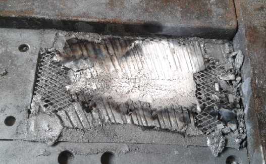 I guess I
torched the second side a bit too
long or too hot. Suddenly the zinc powder caught fire. I tried to blow
it out 3 or 4 times, to no avail. It burned fiercely with flames, with
flames as I recall a few inches tall. What was left in 10(?) seconds
was
yellowish calcined zinc oxide.
I guess I
torched the second side a bit too
long or too hot. Suddenly the zinc powder caught fire. I tried to blow
it out 3 or 4 times, to no avail. It burned fiercely with flames, with
flames as I recall a few inches tall. What was left in 10(?) seconds
was
yellowish calcined zinc oxide.
My first conclusion was that zinc powder has a lot of
energy in it - it should make a good battery electrode!
I did another one but I only torched the one surface, more
lightly. Then on the 17th I was going to put together a cell and my
brain came to life. "What about the jell? That's what's supposed to
make electrodes last forever."
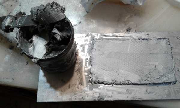 I took the
soap and Veegum mix and added it to a small
ointment jar full of zinc. This made a zinc paste. If I had used a
bigger jar or less zinc I wouldn't have made a mess. But once it was
mixed, no more zinc powder going everywhere. I took the nickel plated
copper screen and pasted it up. It was about 30 grams. (Hopefully well
over 20 amp-hours of zinc. Since the largest use of Veegum is in
cosmetics and the zinc powder color is identical, I think I've
uncovered the secret of the Tin Woodsman's makeup in The Wizard of
Oz movie.)
I took the
soap and Veegum mix and added it to a small
ointment jar full of zinc. This made a zinc paste. If I had used a
bigger jar or less zinc I wouldn't have made a mess. But once it was
mixed, no more zinc powder going everywhere. I took the nickel plated
copper screen and pasted it up. It was about 30 grams. (Hopefully well
over 20 amp-hours of zinc. Since the largest use of Veegum is in
cosmetics and the zinc powder color is identical, I think I've
uncovered the secret of the Tin Woodsman's makeup in The Wizard of
Oz movie.)
I put this in the oven for an hour at 275°F to dry
before (one more time) torching it to put a "skin" on it next to the
separator paper. (Oops, no picture.)
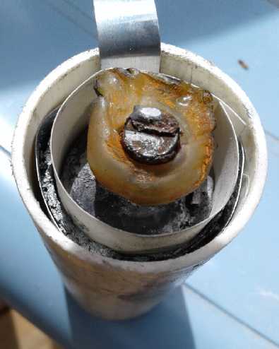 I put it together into a second Mn-Zn cell.
Drying the MnO2 electrode in the oven at 270°F caused the plastic
top piece to shrivel. It performed better than the first one, but the
plastic pipe leaked and after running some load tests I got tired of it.
I put it together into a second Mn-Zn cell.
Drying the MnO2 electrode in the oven at 270°F caused the plastic
top piece to shrivel. It performed better than the first one, but the
plastic pipe leaked and after running some load tests I got tired of it.
Meanwhile still on the
17th, after I had done the Mn-Zn cell, I
thought I would try out the lead-zinc, Pb-Zn. That should be a high
current cell.
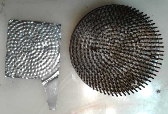 I cut a sheet
of zinc flashing the size of the Pb
motorcycle battery with a tab to connect to. How was the zinc paste
going to stick to that? I took the plate, the large flower pin frog and
some foam out to the hydraulic press. With the foam for a cushion, I
pressed the zinc into the frog's (?)teeth. I stopped at 2 tons
pressure. I was already risking having the pins suddenly bend over. The
pins never go as far into the material as I want, even soft zinc, but
it did manage to raise ragged edges and make small holes.
I cut a sheet
of zinc flashing the size of the Pb
motorcycle battery with a tab to connect to. How was the zinc paste
going to stick to that? I took the plate, the large flower pin frog and
some foam out to the hydraulic press. With the foam for a cushion, I
pressed the zinc into the frog's (?)teeth. I stopped at 2 tons
pressure. I was already risking having the pins suddenly bend over. The
pins never go as far into the material as I want, even soft zinc, but
it did manage to raise ragged edges and make small holes.
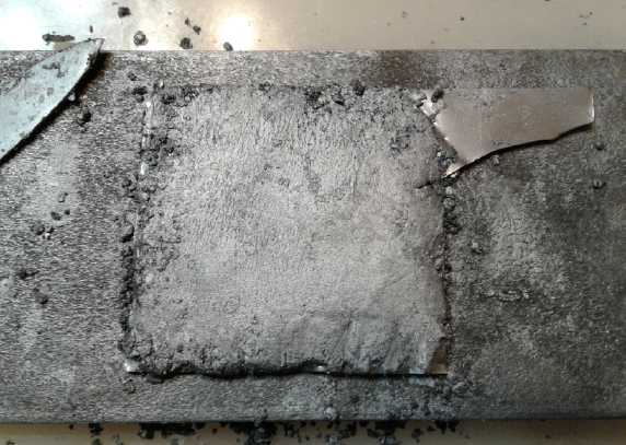
Then I buttered the toast with zinc butter; in this case,
one piece of toast, buttered both sides. It weighed 20 grams, mostly
"butter" - more than a match in amp-hours for the two lead plates (125
g), I suspect. I'll put this one "-" zinc electrode between the two "+"
lead oxide plates. If I don't think it's enough current, I'll make two
more single sided plates and put them on the outsides of the lead
plates. Four faces interface instead of two should double the current.
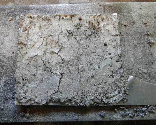 I
put it in the oven at 260°F for an hour to dry the
paste. That ended the day.
I
put it in the oven at 260°F for an hour to dry the
paste. That ended the day.
Lead-Zinc Cell
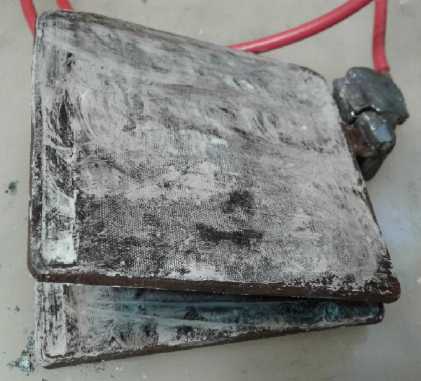 Right: Lead dioxide electrodes painted with CaO
Left, testing: Not much to see, cell 'sealed' with modeling clay
I torched it the next
morning (18th) and painted calcium
hydroxide on all four faces of the lead plates. [Later: Impure
chemical! Apparently the long unsuspected cause of self-discharge in
all my cells.] Then I put the Pb-Zn
cell together in its original compartment in the Pb-Pb case and added
what seemed like quite a lot of KC2O4 electrolyte
to fill it and flood
the plates.
It started off reading 1.888 volts. That seemed like a
good start! Of course both electrodes should have been pretty much
fully in their charged states. I put a 1 ohm resistor across it and it
started with about 1.6 volts (1 ohm, so volts=amps), but dropped in 10
seconds to somewhere just over an amp. Then I put it on charge for a
few minutes at 2.0 volts input and it was drawing 90 mA. (With 2.1
volts input it was over 200 mA. With lead and zinc, there is no "too
high" voltage as with manganese, just "too much current" - however much
current that is, making bubbles and heat.) Then I left it off for a few
minutes and it was
sitting at about 1.9 volts. With the 1 ohm load it held 1.53 volts
steady after 10 seconds. When I put it back on charge it drew 220 mA,
dropping to 110 in a few minutes.
For a second time I took it off charge and after a few
minutes it was 1.93 volts. With the 1 ohm load after 10 seconds it was
doing 1.55 V. I kept it on for 30 seconds, at which time it hit 1.50 V
and the 5 watt resistor started getting warm. Back on charge it started
off drawing 270 mA. (Hmm, I had the power supply limited to that
value!) Soon it was less, but I raised the current limit on the supply
to 1/2 an amp.
These several tests occupied less than an hour. Lead might
be heavy, but I was starting to like the performance of the chemistry!
Or was it the performance of the configuration?: relatively thin plates
of lead and zinc instead of absurdly fat electrode cylinders. Or was it
the combination? I decided I should try out an Mn-Zn cell with several
thin plates instead of thick electrodes. OTOH, Mn is very slightly
soluble in oxalate. And how sure was I that it wouldn't form
permanganate? Might it not last 'forever'? If not, how long would
it last? I looked up the figures again in the Wikipedia Solubility
Table. Well, really it's only twice the solubility of nickel
hydroxide, and nickel [oxy]hydroxide electrodes in potassium hydroxide
last a very long time.
Metal
|
Solubility of Metal Oxalate
(units: grams per 100 mL)
|
Solubility of Metal
Oxide or Hydroxide
|
Nickel
|
.0012
|
.013
|
Manganese
|
.024
|
3.2*10^-4 |
Lead
|
6.5 * 10^-4
|
1.6*10^-4 (II)
7.2*10^-11 (IV)
|
Zinc
|
1.4*10^-9
|
(no figure given)
|
Potassium
|
36
|
112
|
Calcium
|
6.7*10^-4
|
.182
|
Copper
|
2.2*10^-10
|
8.1*10^-7 (I)
1.7*10^-6 (II)
|
I note that the solubility
of potassium oxalate as an electrolyte is similar to that of
potassium chloride (34.2). Also that any calcium that forms oxalate is
likely to be pretty inert. That will probably help further stabilize
the
Mn oxides in the electrode.
The voltage was also appealing (call it 1.71429 volts
nominal under load?), thus needing 7 cells to make 12 volts instead of
8.
I left it off charge for a couple of hours. The voltage
was down to 1.773. Bubbles were coming up every few seconds from
somewhere under the negative terminal. The voltage of the zinc being
higher than that of hydrogen dissociation from water (the lower dotted
line in the Pourbaix diagram), any air entering the electrolyte should
be causing the zinc to discharge itself and make hydrogen gas. The cell
needed to be, if not sealed, at least capped off so air wasn't
circulating into it. (This also applied to the Mn-Zn cells.) (Also note
that zinc wouldn't work in water except for the "hydrogen overvoltage"
effect of the zinc itself that keeps the water stable.)
After a couple more hours, it was down to 1.730 volts. I
covered the top with modeling clay. I put it back on charge and at
first it drew .5 amps. It soon started going down, but I raised the
current limiting to 3/4 amp.
In spite of the modelling clay "seal", it still seemed to
drop down to 1.73 volts in a while. But why not? According to the
diagrams it should be Pb +.48 and Zn -1.2 = 1.68 volts. Why should I
expect it to stay up at 1.8 or higher? Just because it was 1.888 V when
I first filled the cell, I guess.
I tried a .5 ohm load. It held 1.25 volts (2.5 amps) for
10 seconds, and was still about 1.1 V after 30 seconds with the
resistors getting warm. Then I tried a plain short circuit. It started
out a little over 5 amps and dropped to about 4.85 after 10 seconds. I
can't help but reflect that that's less than the 8 amp alkaline "D"
cells. However, it also probably has less common surface between
electrodes. Current should double if I put two more plates on, even if
they had only a few grams of zinc.
Later I put it back on charge from 1.677 volts. I lowered
the charge voltage to 1.9 volts, and it was drawing .43 amps. Later on
it was down to around 60 mA and when the charge was removed the voltage
drop was much slower, taking somewhere around 1/2 an hour to drop to
1.8 volts. I left it off overnight and in the morning it was 1.711
volts. With a 1 ohm load it then put out just over 1.5 volts and 1.44
after 10 seconds. Back on charge it started out at .32 amps. I cut the
charge voltage from 1.9 to 1.8 (actually about 1.83 - the power supply
has no fine adjust) and that current cut in half to .16 amps. In an
hour it was
down to 40 mA and I could hear bubbling from inside the cell. I
'unplugged' it and the voltage dropped only very slowly. By 1.79 volts
it was only
dropping 2 mV/minute. I think I'd call that "fully charged". Toward the
end of the day it was at 1.693 V. 1 ohm load, 10 seconds: 1.395 V. A
little later it read 1.685 V. I connected .5 ohms again, and again it
put out 1.25 V for 10 seconds.
I put it back on charge at 1.8 volts at 7 PM. It started
out at 250 mA and worked its way down to 90 in 15 minutes.
By this point, on the 19th just the day after making it, I
tentatively decided that nickel-zinc was pretty hard to do and the
current drive and longevity of manganese-zinc were somewhat
questionable. Lead-zinc seemed to offer the most certain way forward
for small production.
Load Test
A while later I took it off and did a 5 hour load test
with an 11 ohm resistor. (I couldn't find a 10 ohm except 1/4 watt.) So
at 1.6 volts, that's 145 mA. It sat at 1.774 volts and dropped to 1.726
when I connected the load. It was down to 1.7 in 3 minutes, and 1.6 in
23 minutes. It hit 1.5 in an hour and 1.4 in a little over 2 hours. In
3 hours it was around 1.35 volts. After that I forgot about it for 2
hours, and found it dropping pretty quickly. It crossed below 1.000
volts almost right on the 5 hour mark. I'm sorry I missed around the 4
hour mark, when it might have been around 1.25 volts - and I might have
turned it off then.
Adding up the current for each hour using the average (the
mean) voltage during that hour: 1.6v/11ohms=.145 A (*1 hr = 1.45 AH);
1.45/11=.132 AH; 1.375/11=.125; 1.25/11=113; 1.15/11=.105. Total
.145+.132+.125+.113+.105=.620 AH. Another disappointing result. But it
wasn't entirely dead yet, and it was a lot more than I've had from
anything else so far. Theoretically if the 20 grams zinc electrode was
even 15 grams of zinc powder, 15*.820 mAH/g = 12.3 AH.
If the 125 gram lead electrodes were maybe 70 grams of
lead dioxide we should have had .820*(65.4/(207.2+32))=15.7 AH.
Well...! It was certainly never going to be 15.7 AH as a lead acid
cell. Typically lead-acid is around 30 WH/Kg, and each cell had 1/4 Kg
total of lead, so 7.5 WH. Since it would be 2 volts, that's 3.25 AH. If
I have all that right, apparently lead only yields about 15% of its
theoretical capacity in practice. I'm sure zinc is higher. I decided to
fill one of the cells with acid and test it as originally made.
I did that and within 15 minutes concluded that it was
going to put out way over an amp-hour, with low voltage drop, so my
zinc electrode must be the weak link. Either that or the electrolyte
doesn't work very well... but that would explain low currents, not low
amp-hours. The next test would be to use the oxalate and calcium in a
lead-lead cell. Lead-Lead at neutral to alkaline pH is just one volt
instead of two, but it should work fine. I ran the lead-acid cell 5
hours and having
delivered about a whole amp-hour, the voltage wasn't down much at all.
It was obvious it was going to run for at least several more hours no
problem.
So at least that proved definitively that my zinc
electrodes were the problem.
I didn't get around to trying the Pb-Pb in alkaline
oxalate.
I wonder if the lead can be coaxed into putting out more
of its theoretical amp-hours per kilogram in the alkaline cell than in
acid? Maybe not likely, but not impossible either. And it certainly
seems likely it'll last far more cycles.
My Crappy Electrodes
Unless I could make better electrodes, I wouldn't be
making
real batteries! Well, perhaps I should have known even a zinc powder
electrode has to be compacted? Or was it the other way around? Should I
have a coarser zinc powder so the electrolyte can get in better?
I had noted in a paper I read that their zinc powder was much coarser
than
mine - "20 to 200 mesh" where mine was virtually a nano powder. These
people had experience making their "AA" cells. Maybe my powder was
so fine it was behaving like a solid and the electrolyte wasn't getting
in. In fact, maybe that's been my main problem trying to make good
electrodes all along. Don't most electrodes look grainier than
mine? I concentrate on "super fine" to get the most surface area per
volume of particle, and I compact the heck out of them, but if there
are no spaces for the electrolyte, none of the inside is surface area!
I might as well be using solid sheets!
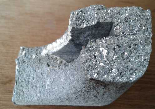
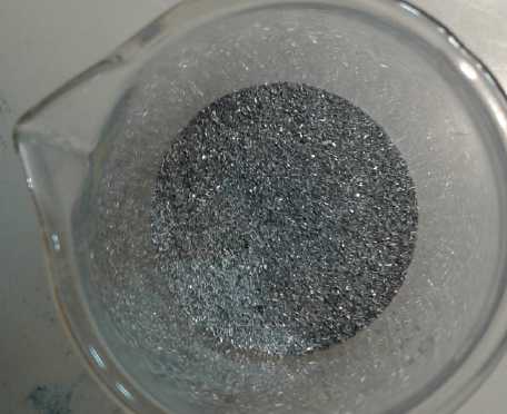 I
took a chunk of cast zinc from an old ship electrode,
that had big coarse crystals, to bash - or file - into bits. I ended up
filing it. I used a fairly fine file and a very coarse one to hopefully
get variety. I don't suppose that with so many rather coarse particles
this one'll give the full 8.9 theoretical amp-hours from the 10.9 grams
of zinc either. But if the electrolyte wasn't penetrating and now is,
performance should be substantially improved. (Perhaps a certain amount
of the fine powder would be beneficial too, as long as it wasn't enough
to clog things up, but I didn't want to try that in first exploring the
"grainy electrode" idea.)
I
took a chunk of cast zinc from an old ship electrode,
that had big coarse crystals, to bash - or file - into bits. I ended up
filing it. I used a fairly fine file and a very coarse one to hopefully
get variety. I don't suppose that with so many rather coarse particles
this one'll give the full 8.9 theoretical amp-hours from the 10.9 grams
of zinc either. But if the electrolyte wasn't penetrating and now is,
performance should be substantially improved. (Perhaps a certain amount
of the fine powder would be beneficial too, as long as it wasn't enough
to clog things up, but I didn't want to try that in first exploring the
"grainy electrode" idea.)
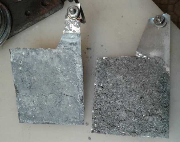 Fine "nano" powder and grainy powder zinc
electrodes
Fine "nano" powder and grainy powder zinc
electrodes
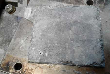
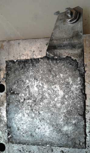 Hydraulic pressed: the nano powder one worked
worse, the coarse powder one worked better.
Hydraulic pressed: the nano powder one worked
worse, the coarse powder one worked better.
I put the new electrode in and the cell back in its
'slot'. It read 1.6xx volts. I put it on charge at 1.8 volts first
(=1.83 today). It started drawing 250 mA. A .5 ohm load test showed it
to be not as good as the other one. It dropped below 1 volt before 10
seconds. I suppose the key is mixed sizes including both the coarse and
the very fine in the right proportions.
Or... maybe it still is in compacting, even with an
electrode of conductive zinc particles? The new electrode
underperforming the old one, I decided to try just squashing the old
one down with a few tons of force once it was dry again. For that I put
it in the oven at 270F again. Then I pressed it between two pieces of
stainless steel at 12 tons. I swapped the electrodes back. But it
wasn't as good as it had been before I pressed it. That seemed to
confirm that the powder was too fine and not letting electrolyte in,
because squashing the particles made it worse.
I took the grainy electrode and pressed it at 10 tons.
After that it had that sheen and didn't look grainy except where the
lower areas were. It also had excess electrolyte oozing out of it as I
had forgotten to dry it, and now it had less volume to hold liquid. I
fear I might have overdone it. It worked better than it had before.
But neither one was even as good as the first one with the
fine powder just made into paste and pasted onto the zinc sheet. This
wasn't going the way I expected or hoped!
Might they improve with cycling? I put on a 1 ohm load for
a minute (it dropped to 1.21 V=A) then 'blasted' it with 2 volts of
charge, from which it at first drew an amp and was still doing .4 some
minutes later. Perhaps it was just starting from the high charge, but
with the 1 ohm load
it held 1.28 volts after 1 minute the second time. Third time I let it
run 4 minutes and it crossed below 1 volt at the end. I turned the
charge voltage down to 1.9 but it still did 1.5 amps when reconnected
and stayed over an amp for a while. The fourth time proved almost
identical to the third, except I ran it for another minute (5 minutes)
and down to .94 volts. (Hah! Around 6 amp-minutes: 1/10th of an
amp-hour.) Fifth try was almost the same as the fourth - 15
or
20 millivolts higher toward the end of the 5 minutes. But it was
probably just a bit more charged to start. The sixth (and last for the
night) was virtually identical to the fourth. Not the sort of promising
cycle-by-cycle improvement I was hoping for. It's disheartening to
watch the voltage drop and drop by the second when the lead acid stayed
over 2 volts for hours. But I was actually cycling it, at least a bit
(and rather quickly). Significantly it seemed to indicate stability: it
wasn't getting worse with each cycle, which my earlier cells in
potassium chloride usually if not always always seemed to do.
So I thought, what about one more try at making a
practical electrode? I could use some coarse powder and some fine
powder, and compact it but much less, 3 or 4 tons. (and that's over the
whole electrode, 35 sq.cm. So 4000/35 = 115 Kg/sq.cm.) Was there
anything better than perforating the zinc sheets as a backing? I had no
zinc mesh or 'zinc foam'. Then I remembered I had some zinc wire...
Nope. Zinc coated wire. I decided that wasn't good enough.
There were also little bits of the zinc sheet metal. I could cut them
into really thin strips and throw them in. I can't think of anything I
have that would be as good as the powder being just right. Maybe some
"U" shaped zinc strips well squashed down around the edges ("coined",
like the lead electrodes) to help hold things together?
Or, seeing that I had managed to perforate the zinc
sheets, maybe a flat "pocket electrode": zinc powder inside a shell of
perforated sheet zinc? The pin frog, even pressed in 3 or 4 times into
each sheet, couldn't make anything like the density of holes of
commercial pocket electrodes. Still, with thin strips of sheet thrown
in and different sizes of powder, it seemed to have promise. (And don't
forget to etch the sheets this time!)
It would seem that what's really needed are a lot more
tiny pores. What if I added some sort of tiny "sandy" grains to the
electrode that would dissolve out in a solvent, leaving little holes?
That just might make a tremendous difference. But what substance and
what solvent?
Zinc Sheet Electrodes: Best Ones Yet!
On the 21st I thought: I wasn't getting anything like the
theoretical amp-hours from the zinc... what would I get if I just used
etched zinc sheets? I folded up my perforated, etched sheet that I had
intended to make into a "pocket electrode" cover and stuck it in the
cell. The voltage started at 1.70 and rose in a few minutes to 1.76 by
itself.
With a 1 ohm load it dropped to a volt in one minute and
to .85 in two. That wasn't very good, but it wasn't so much worse than
my others, either. And it soon sprang back to 1.625 volts, so it was at
least partly a question of insufficient convoluted/fractal interface
area rather than insufficient material.
So... what about several perforated, etched zinc sheets
simply stacked together? I also thought about running some through the
rolling mill and making them thinner - same volume but more surface
area with less "dead weight" interior. Then too, one might add a little
powder or coarser filings between the sheets, too. I didn't see any way
that could be anything but helpful. And then press it down to make it
thinner and less lumpy, but not to the extent of forcing the sheets
into close contact.
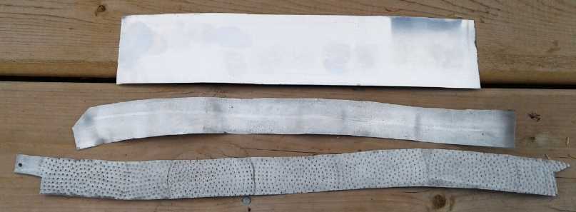 So I tried it.
I put a textured roller on the rolling mill
to give yet more surface area. It wasn't practical to put the 3" wide
sheets through the 3" wide rolling mill because they didn't stretch
evenly so they were always running over the edge. So I cut the strip
lengthways. Even with 1.5" width I sometimes had to stop, unscrew the
pressure, and realign the sheet. That made it narrower than the Pb
electrodes. I simply folded it up, and I did it a bit crooked so it
came out wider than the individual pieces- about the width of the Pb
electrodes.
So I tried it.
I put a textured roller on the rolling mill
to give yet more surface area. It wasn't practical to put the 3" wide
sheets through the 3" wide rolling mill because they didn't stretch
evenly so they were always running over the edge. So I cut the strip
lengthways. Even with 1.5" width I sometimes had to stop, unscrew the
pressure, and realign the sheet. That made it narrower than the Pb
electrodes. I simply folded it up, and I did it a bit crooked so it
came out wider than the individual pieces- about the width of the Pb
electrodes.
size
Before rolling: 13.5" x 1.5"
After rolling: ~19" x 1.5" (460 mm x 37 mm = 170 sq.cm; 170 * 2 faces =
340 sq.cm)
Etched and not yet brushed
off zinc
sheet
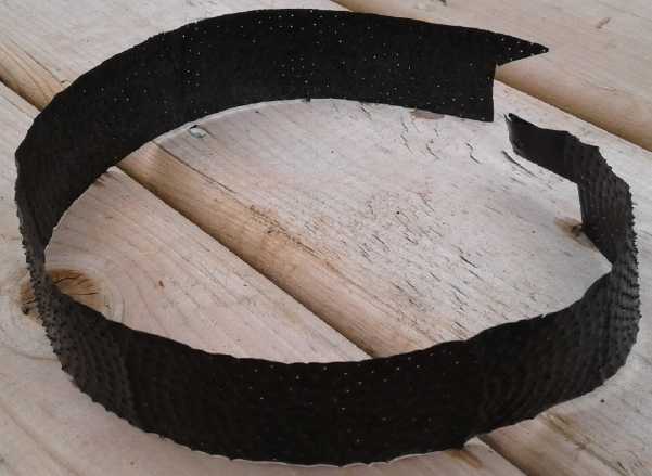 weight
Before etching: 20.3 g
After etching: 18.3 g
I tried a 1 ohm load
without charging first. It wasn't as
good as the first electrode, dropping to 1.18 volts in one minute. But
it didn't drop below a volt for well over 3 minutes and it ended 5
minutes at .86 instead of .84 or less. When I put it on charge at 1.8
volts it drew over an amp at first. I left it until it was down to 90
mA before I tried again. It wasn't nearly as good. Later it was only
drawing 40 mA. I tried an 11 ohm load and compared it to the figures
from the first 11 ohm test. It started out almost 90 mV lower and kept
underperforming until at 1/2 hour it was well over 100 mV lower. I
stopped there and recharged. I started 11 ohms again for a few minutes
and it was only 60 mV below - an improvement. So I tried 1 ohm. It was
better than the second time. It did put out over 5 amps monetarily when
shorted, but that dropped quickly to 3.5 in 10 seconds and under 2.5 in
30.
Somewhere after that I made a dozen more perforated zinc
sheets, but I haven't used them.
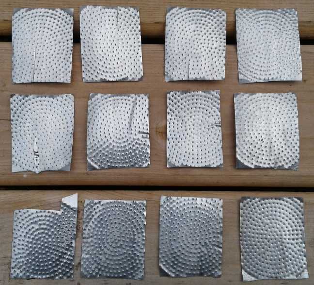
Well, it didn't change much over a couple of days. What
about the ultimate in simplicity: one plain sheet of zinc next to each
face of the lead electrodes? With just one thickness, they didn't need
to be perforated to let electrolyte through to the sheets behind. On
the 22nd I cut just three sheets, rolled them just enough to texture
the surface and then etched them. (hmm... no pictures)
weight
before etching: 21.4 g
after: 20.25 (6.75 g each)
Now there were 3 plates instead of 1, covering all 4 faces
of the lead oxide electrodes. (BTW I used a different cell and Pb
electrode, next to the first one, which I didn't take apart.) The
voltage was way over 1.8, so I tried a short and got well over 6 amps,
briefly. A .5 ohm load test showed it was much overloaded, soon
dropping under a volt. I tried 1 ohm. It dropped to just over a volt
within a minute... then it rose back up to 1.11 volts, and dropped very
slowly from there. After 5 minutes it was still 1.043 volts. Then it
went up over 1.1 volts and I shifted the aligator clip leads around.
(Darn aligator clip test leads - so often poor connections!) It rose to
1.179 by the 7 minute mark, and I turned it off at 8 minutes doing
1.092 volts=amps. It was apparent it would run for quite a while - at
least substantially longer than the others - even if it was somewhat
overloaded.
I left it on charge some hours and it had dropped from 1.3
amps to to around 30 mA charge current. A short circuit yielded over 7
amps for a moment. I didn't leave it shorted because I wanted to try an
11 ohm load test. That started off discharging 25 mV below where the
first and best one that I recorded showed, for the first 10 minutes.
But this time I wanted to see where it was after an hour or two. For
the first hour it was dropping about as fast as the first one. But
after an hour and 15 minutes or so, the rate of drop decreased so that
by the two hour mark, it was virtually the same voltage. with 3 zinc
sheets no heavier in total than the first single electrode. By
the 3 hour mark it was starting to drop faster. The performance didn't
seem very different. But by 4 hours the voltage was probably above. At
5 hours the other one had been down to 1.000 volts, but this one was
still 1.160 so I decided to keep it running. However it was 1 AM.
Knowing that batteries recover voltage but quickly drop back to where
they were when a load was resumed, I disconnected the resistor and left
it idle overnight. In the morning it read 1.474 volts. When I put it
back on, it took a while dropping back down, starting at 1.348 volts
and still being 1.245 after 10 minutes. It took 1/2 an hour to get back
down to where it had been. To make up for it, it continued dropping
faster. And as I surmised, once below 1.1 volts it dropped rapidly.
This electrode ran for 6 hours and 11 minutes instead of 5 hours 0
minutes - over 20% longer. Amp-hours delivered:
.140+.130+.125+.115+.109+.105+.019=.743. Even if that's under 5% of the
theoretical 16 amp-hours of 20 grams of zinc, it's still a working
electrode. And 743/620=20% more than the first uncompacted fine zinc
powder electrode, the previous best. It recovered to 1.318 in half an
hour or so and drew all but 2 amps when placed on charge.
So even while they got nothing like the theoretical
amp-hours of zinc per weight, the 3 simple plates seemed to outperform
any of my attempts to make a zinc powder electrode. Yet surely most of
the zinc is locked up in the interior of the sheets. Only the [textured
and etched] surface wetted by the electrolyte reacts. Interface area of
the first electrode was 52*64mm*2 sides = 70 sq.cm, and for the second
one with 4 sides facing the PbO2 electrodes, 140. So to put out, say,
1.5 amps, would be 21 mA/sq.cm for the first electrode but only 10.7
mA/sq.cm for the plates. It's not high, but over 10 is at least in the
right order of magnitude for a "real" battery. Zinc is cheap. It
depended what one wanted to do with the battery. If weight and size
were no object (ie, off-grid electricity storage), one merely needed to
use enough of it for the current and storage requirements. That would
be a good start for a market, then if the electrodes could be improved
sufficiently one might go for the EV market.
24th: Further 1 ohm load tests (far faster than 11 ohm tests!) showed
gradual improvement in the zinc plate electrodes. Running it until a
little under one volt, the cell discharge went from 6 minutes to 7 to 6
to 8. 8 is 33% better than 6. Then I upped the charge to 1.9 volts in
order to decrease the time between runs. Maybe it would get up to 10%
of the zinc's theoretical capacity or better by itself with cycling?
The lesson I took was that solid plates are "good enough"
electrodes - better than anything else I've made. And they're the
easiest to make and zinc is cheap. The thing to do then, if the plates
don't have much "oompf" per square centimeter of interface area is to
get more square centimeters. Naturally the first thing I thought of was
to have lots of big plates all stacked up - and of course with positive
plates in between. But what about a plate with an accordian fold or
similar? That could have a lot more surface area, albeit by being
substantially thicker. That would be easier to make if the zinc sheet
was thinner and softer. If it was (eg) copper I would roll it thinner
and then heat it red hot to anneal it, then roll it thinner again. But
the last time I heated some zinc - powder - too much it caught fire.
Would sheet fare better? What was the best way to do this? And just how
thick was it, anyway? The calipers said .0075" or about .2 mm.
Actually, that's pretty thin already. There has to be a certain amount
of inside strength when the surface is being converted to oxide and
back, to hold the electrode together. But what is a realistic minimum?
Is .0075 already there? .00375" electrodes would be half the weight of
.0075".
Perhaps the thing to do is to buy some different
thicknesses to try out. OTOH, zinc "moss killer" strips for roofs is
cheap - and probably all the same. I decided to see what was available
locally (nothing) before looking on line.
Or... what if I just etched them longer? (or in new ferric
chloride instead of 'worn out'? or both?) Perhaps they'd develop more
convolutions at a micro or nano scale... and the longer they're etched,
the thinner they'll get. So it's also another way to try out thinner
pieces.
Shaping Plates to gain More Surface Area
(about 2x desired sizes)
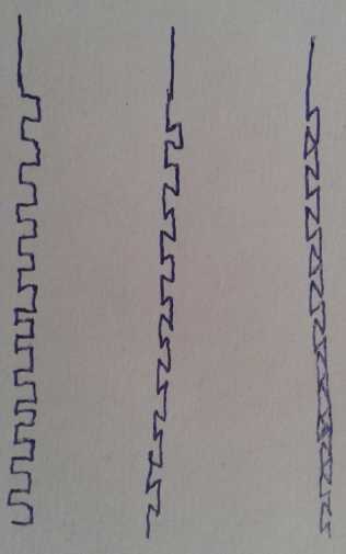 I could
imagine some high-pressure stamp that imparts a convoluted shape and
texture to the plates. A bit like the pin frog, but just texture rather
than holes. (Though holes wouldn't hurt.) Or perhaps a convoluted
roller to run the sheets through... my jewellers rolling mill was the
right idea but it doesn't have the really convoluted textures I'm
after, and the lower roller is always smooth - only the upper one has
textured rollers that can be swapped around. It would be nice to get
the amp-hours figures up to 15 or 20% of theoretical - or even 10%,
rather than the 5% of the set of 3 plates I started with.
I could
imagine some high-pressure stamp that imparts a convoluted shape and
texture to the plates. A bit like the pin frog, but just texture rather
than holes. (Though holes wouldn't hurt.) Or perhaps a convoluted
roller to run the sheets through... my jewellers rolling mill was the
right idea but it doesn't have the really convoluted textures I'm
after, and the lower roller is always smooth - only the upper one has
textured rollers that can be swapped around. It would be nice to get
the amp-hours figures up to 15 or 20% of theoretical - or even 10%,
rather than the 5% of the set of 3 plates I started with.
Then (23rd) I thought of a stamp that might rather readily
be made: thin plates of hard steel bolted together, every second one
sticking up a little farther making "fins" and "troughs", maybe 2mm
wide and 2 or 3 mm deep. Two of those would be pressed together with
the zinc between them to make up-down ridges. The zinc would
(hopefully) stretch out to make the edges of the troughs, so it would
be the same zinc with more surface area for its volume. (2 mm deep with
straight sides would double the surface area. Pushing it even further
together (somehow), somewhat closing the tops of the troughs on both
sides, would bring still more plate substance and surface into the same
space.)
But I'll leave this topic now. [And later I found another
idea: etch in lots of little holes and have two plates.] The plates
even flat are sufficient for batteries. So we have electrolyte and
negative electrodes that can be done at home to make practical working
batteries. Next: what matching electrodes might go between those plates
on the positive side?
Zinc Plates and What?
What about lead oxide electrodes? Buying new batteries to
salvage from for homemade is costly and seems self defeating. One might
make them of
course, but taking them out of old batteries is probably a much easier,
and cheap, way to get the best electrodes. But how to get ALL the
sulfate out of
the plates? Zinc sulfate is soluble, so there can't be any sulfate left
in the cell. I started thinking about chemicals. But what about just
hot
water? Might the sulfates be boiled off?
But I started thinking of manganese electrodes again. Lead
electrodes are heavy. Even if I only care about getting working
batteries at first, I'd certainly like to keep improving them
incrementally until they're good for EV batteries, and Mn-Zn would
certainly be lighter even if the zinc in Pb-Zn was weightless.
Manganese-Zinc 'Prismatic' Cell with Copper
If I was making low capacity plates from zinc , why not
try making matching low capacity plates of manganese oxide and stack
them all together? The question is first what to use for current
collectors and second how to 'glue' the oxide and graphite powder mix
to them.
Copper as a current
collector?
Similar to zinc the "Cu(OH)2-" ion shown here only develops
above pH 13 at room temperature. But transitions near "zero
volts" don't make copper a very appealing electrode substance.
Around manganese's +.25 volts transition region however, or
even if "overdischarged" to about 0 volts, copper doesn't
change state, so if a surface oxide layer forms and stays,
it won't be subject to change over time with cycling.
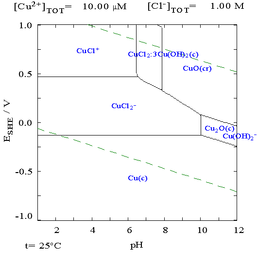 When I used copper, nickel or stainless steel metal (also solder) in a
positive electrode before, they corroded away in no time. That seemed
to leave only graphite. But back then I was using potassium chloride
for electrolyte, and most metals are soluble in chlorides. In potassium
oxalate, might a metal form an oxide skin (eg, CuO) and stay solid
inside, as aluminum does in air? It seemed worth trying. If I used a
copper mesh and pasted the powders on, they should have a fair chance
of staying put. Then if the copper didn't corrode away, it should be a
great electrode. I could also try the nickel foam and stainless steel
mesh. [Thought of Later: as well as, and maybe especially, monel or
cupro-nickel, which is noted for very strong resistance to corrosion.]
When I used copper, nickel or stainless steel metal (also solder) in a
positive electrode before, they corroded away in no time. That seemed
to leave only graphite. But back then I was using potassium chloride
for electrolyte, and most metals are soluble in chlorides. In potassium
oxalate, might a metal form an oxide skin (eg, CuO) and stay solid
inside, as aluminum does in air? It seemed worth trying. If I used a
copper mesh and pasted the powders on, they should have a fair chance
of staying put. Then if the copper didn't corrode away, it should be a
great electrode. I could also try the nickel foam and stainless steel
mesh. [Thought of Later: as well as, and maybe especially, monel or
cupro-nickel, which is noted for very strong resistance to corrosion.]
The area of the electrodes was 35 x 70 mm for 24.5 sq.cm interface,
times two zinc plates is 49 sq.cm total.
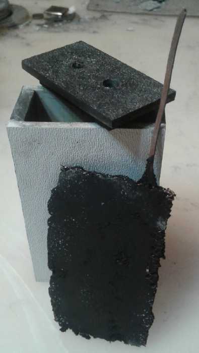 I pressed the
electrode, the copper mesh with the powder sprinkled on and with a
little of the dishsoap squirted on top from the bottle, simply between
two flat pieces of stainless steel with 10 tons force. It came out just
a couple of millimeters thick and I trimmed the edges, which flaked off
easily. The copper mesh with a wire for a terminal weighed 3.8 g, and
when the electrode was pressed onto it, 13.3 g.
I pressed the
electrode, the copper mesh with the powder sprinkled on and with a
little of the dishsoap squirted on top from the bottle, simply between
two flat pieces of stainless steel with 10 tons force. It came out just
a couple of millimeters thick and I trimmed the edges, which flaked off
easily. The copper mesh with a wire for a terminal weighed 3.8 g, and
when the electrode was pressed onto it, 13.3 g.
The composition of the MnO2 electrode was 20 cc of Mn
oxides mixed with graphite or carbon black from dry cells (unknown
proportions), mixed with 4 cc of Veegum and wetted with a couple of
grams of Sunlight dishsoap.
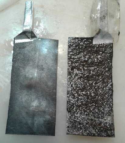 Etched Zinc sheet electrodes.
Just the left one has been brushed off after etching
On the other side, two pieces of zinc weighed 8.8 g before
etching. I forgot to weigh them after but I etched them for 30 seconds
instead of 20. I'll estimate 7.5 g.
The body of the cell was a square box of ABS plastic, made
quite a long time ago. I dumped the previous test cell pieces that were
in it and cleaned it out.
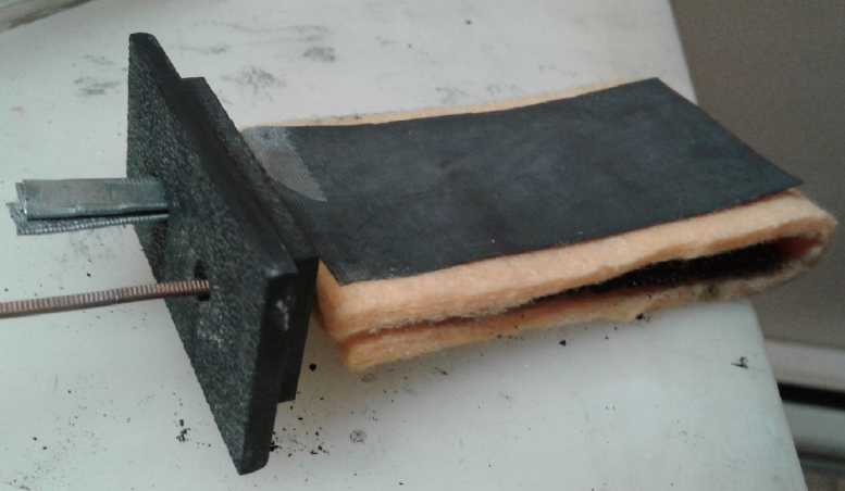 I put the cell together
with rayon cleaning rag as a separator (fat material like the lead-acid
cell's separators), and then I added a couple more similar pieces
around the outsides to fill in the excess space in the cell.
I put the cell together
with rayon cleaning rag as a separator (fat material like the lead-acid
cell's separators), and then I added a couple more similar pieces
around the outsides to fill in the excess space in the cell.
The cell started out around 1.3
volts and drew over 100 mA when I hooked it up to charge. That was more
encouraging than the previous Mn-Zn dry cells. After a while on charge,
it would put out an amp momentarily if shorted. But unlike most of my
cells, that current soon stopped rapidly dropping off, at .76 amps. It
was still doing .75 amps after 10 seconds... and .72 amps after 30.
This is why I wanted an electrode substance that conductive graphite
could be added to. It's so much easier to get a good conductive
electrode.
.75 A / 49 sq.cm = 15 mA/sq.cm. That's not high, but it's in the target
range. Later it gave an amp for 10 seconds, still later 1.6 amps. Then
disaster struck... The copper terminal wire appeared to disconnect from
the mesh and currents went way down. Wiggling it around brought it
back, but the currents were never as high again. It needed a rivet or
something to secure the connection.
I found a bag of little rivets (thankfully it was stashed
in a "battery related" box). I took the cell apart to see what could be
done at this point... and discovered something remarkable. There was
only one zinc electrode instead of two! I had somehow not installed the
other one when I finally assembled the cell with the separator and
filler cloths. That meant it had been doing this fine job with half the
interface area I thought, 24.5 sq.cm, and that meant 30 mA/sq.cm
current density. And the 1.6 amp short circuit current was 65 mA/sq.cm.
These figures are definitely in good, practical battery current density
range.
Now, about that connection... It was too damp and messy to
think of soldering even if solder wouldn't corrode away. I poked a hole
through the electrode next to the wire and stuck a rivet through. I
managed to squeeze it flat with pliers without the electrode falling to
pieces. I reconnected the cell, this time with both zinc electrodes,
and put it on charge for a short while. Then I shorted it again. It
only gave 1.3 amps, but it stayed up at well over an amp for 10 seconds
and was still .90 amps at the end of 30 seconds. It was after 1 "AM"
(really PM - not yet midnight with the clocks 2 hours ahead of the sun)
so further tests with a full charge awaited morning.
25th: In the morning it
would barely put out an amp, and charging currents seemed to be down
too. My idea of the most likely cause was swelling of the MnO2
electrode because the cell had extra space in it that would allow it to
expand. Perhaps the felt-like cloth wasn't a very good idea? But later
I found it was just the copper wire again making poor connection to the
screen, as wiggling it made currents jump around. Once surface oxide
has formed it's hard to get the solid connection needed to the
terminal. It could be that the copper was corroding away, too. It
didn't seem to be when I had the cell apart. But if it was, it would
become obvious in a day or two(?) when the terminal fell off. If that
was the case, I could (a) try another metal (b) paint the copper with
the osmium doped film (c) go back to graphite positive electrode
current collectors. There's nothing there that can't be made to work
one way or another. But I just don't think - so far - that any special
measures will be necessary.
I also tried refilling the electrolyte, but it hardly took
any. Later with the lid still off and liquid to the top I could see it
was bubbling. It may be that the DES will prove to be a better
electrolyte for any zinc electrode regardless of the plus side. Or I
should be adding hydrogen overvoltage increasing materials to the zinc.
(How to add antimony sulfide to a zinc plate? Maybe I should reread
that patent, where they made various zinc alloys and ran
various experiments with them?)
After weeks of pretty intense battery experiments and
developments in May and June, I had other things to get done.
On the 26th I disassembled the cell and inspected the
copper mesh and terminal wire. They were of course covered with black
copper oxide, but they didn't seem to be corroding away. In chloride
they'd have been long gone. It looks like I've found the metal (or at
least one that works) to use for pH 12 with oxalate, in place of the
nickel used at pH 14 with strong hydroxide. This is another important
find, albeit subsidiary to the electrolyte itself. A metal current
collector is better than graphite both for mechanical strength and for
current capacity.
And I didn't see any dissolved purple "dye" color that
would indicate the manganese was charging to permanganate, which would
probably cut short the life of the electrode.
The disassembly however didn't do the electrode any good.
Some of it fell off the mesh and stayed on the separator cloth and I
rinsed much black powder out of it. I put what was left back together
in fresh(er) electrolyte. The short circuit current was down to under
1/2 an amp - and it still varied if the wire was moved around, since I
hadn't tried to fix it.
It appears this battery, and by extension future ones of
similar design, is a success needing just a single piece copper current
collector. Or maybe cupro-nickel, so noted for high corrosion
resistance? (Can you melt two pieces of copper together with a torch if
you put some flux on them?) I'm pretty sure they now just need
techniques for limited manufacture, then put them to use and see how
they fare over weeks and months - and years - of time.
Self Discharge Problem Solved (I think)
27th (rev.30th): There is, after all this time, still a
self discharge problem with every cell I make. It's quite variable so
sometimes I've thought it had become trivial, but it's always
unacceptable. However I believe at long last I've found the culprit by
process of elimination. I've tried a number of chemistries now and they
all have the same problem. Especially we know for sure that both
regular and alkaline Mn-Zn cells normally have very low rates of self
discharge, having a shelf life of a couple of years, so it isn't
inherent in the electrochemistry. And the lead-zinc cells with the
commercial lead oxide electrodes have it too, so it couldn't be the
Veegum or the dishsoap because I didn't add any to those, or to the
first Mn-Zn "F" cell. The problem could have been the separator paper,
but the lead cells (lead-zinc) came with their own separator sheets
like "blotter paper" or "felt paper"(?) that must work fine (at least
in sulfuric acid). And I tried some felt/cloth separators in the last
cell instead - it didn't help.
So by process of elimination I'm attributing it to
impurities in the electrolyte. I've had the problem for a long time
even when I was using potassium chloride, and the potassium oxalate
came from a chemistry supply. But the calcium oxide was calcium
carbonate from a pottery supply, which I converted in the mini kiln to
calcium oxide in 2012. (And I've been having self-discharge problems
since when? ...Yup.) Of course if the calcium is contaminated, when
changing the electrolyte I'm just replacing it generously with more of
the same. Yes, it all fits. Any hint of nitrates or nitrites would do
it. Chlorides or sulfates might do it. This is where one might want a
chemist on staff to figure it out. Or maybe I just did. Perhaps I'll
order some pure chem supply calcium oxide.
28th: Ooh, look! In addition to CaO, Westlab.com also has
"nitrate/nitrite test strips 0-500 PPM". And I see there's a test for
chlorides with silver nitrate. Maybe I don't need a chemist after all,
just the right stuff to test it myself? And they have microscopes...
Hmm, do I want to spend 200$ or more on a microscope at this point?
I've made out pretty well with just the x4, x10 and x40 microscope
lenses I somehow have so far. I passed on the microscope.
I found I hadn't ordered enough, by 25$, to avoid a 30$
shipping charge. ("Free shipping over 70$") But silver nitrate was over
100$. Unable to think of anything else in particular, I perused their
list of chemicals and ordered some nitric acid (the one common acid I
don't have) for 35$. Only after I placed the order did I realize I
could use it (and a bit of silver) to make a little silver nitrate to
test for chlorides, so it was after all an "on target" thing to order.
(And if you're not using much, a little silver nitrate is better than a
lot of it. As I recall from telescope making in college it can be
explosive stuff.) The calcium oxide, the original and main reason for
the order, was the cheapest item (13$).
I'll remark too that it's great - after all these years -
to have found a chem/lab supply store that doesn't demand 500$ orders
and whose prices don't start at 50$ for every little thing. The other
ones must cater to big institutions with lavish budgets. (read: your
tax dollars?) But why did it take me so long to find out about it, and
then only when someone else gave me their URL? How can it be that it
was so hard to find the on-line store I needed in this day and age of
the internet?
(Awg! I already had a nitrate/nitrite test set! It's in my
aquarium stuff from having fish! I never made the connection.)
I looked back to find out when I first started with the
calcium hydroxide and came to TE News #48, February 2012. Yup. There
was the original idea to use it to get the electrolyte to pH 12-13. (If
only I had thought of the oxalate back then, too!) But I've used that
same (doubtless impure) calcium all along, and that was when I started
having self discharge problems. (I knew I was doing better on self
discharge in a few cells in the earlier years!) After about 2013 my
battery ideas became very occasional work, since I didn't seem to be
making much headway. Working so much in the last three months or so,
with a number of different cells and chemistries, has finally helped me
zero in on the problem, which probably should have been obvious far
sooner. One problem was having only found Westlab for reasonably priced
lab chemicals a few months ago, or I might have tried buying a jar and
trying it out just on spec long since.
I played around in my head with some alternate cylindrical
cell design ideas, too. If copper makes a good current collector,
instead of a carbon rod current collector, use a copper one. Then
there's a multitude of possible designs.
But in order to have plenty of contact area between the
manganese and the copper (really the copper oxide surface layer),
instead of a copper wire use a copper tube or pipe. It can be filled
with something lightweight for strength. That gives the large contact
surface area without a really fat, heavy piece of wire in the middle of
the cell. In fact, a copper mesh "impregnated" solidly around the inert
center might work as well or better. Or maybe a copper mesh filled
inside with MnO2 powder as well as the powder surrounding it? That
could be even larger diameter, with the mesh even just inside the
electrode, near the zinc surrounding. That would have the highest
current capacity.
Or it could even have: an inner hollow plastic pipe
covered with copper mesh for a moderately thin (6 mm?) MnO2 powder
electrode surrounding it, then the outer zinc sheet electrode. This
would give a larger surface interface area with more zinc sheet than a
smaller diameter solid center cell with the same amount of MnO2. Of
course the air space inside the the center pipe would be wasted.
(unless it's actually valuable to help cool the high current cell?)
OTOH... once all these cylindrical cell options and
potential improvements are considered, for unpressurized flooded cells
it's surely easier just to make a flat cell with flat electrode plates
just as big as the cylindrical cell would have. And then one can start
multiplying plates and get higher currents and capacities by just
making thicker cases, without multiplying cells for each electrode pair.
So I ended up deciding cylindrical cells are probably best
saved for making "standard" (but rechargeable) cells, "AAA", "AA",
"Sub-C" (battery power tool size), "C" and "D". For bigger, [probably
flooded] cells with real capacity, the flat plates are better.
Then I came up with what might be a great idea for
multiple plates: fold up a single long piece of zinc, "zigzag", into
many plates each going across to the next one at the tops and
bottoms, with sufficient room for the other electrode between each
plate. Or "zigzagging" at the sides. Line both faces with separators.
This could save a lot of internal interconnections. (Internal joins
inside a cell seem like potential trouble.)
While looking up calcium, TE News #66 also mentioned it,
and there I found an idea I'd long forgotten about: To make a
perforated metal sheet (zinc, copper, nickel), one might use something
like a silkscreen with the desired holes in it, screen it onto the
solid metal sheet, and then etch the metal in (eg) ferric chloride
until the holes were eaten away as and where desired. That might be a
good way to make a one piece metal current collector for a paste
electrode, complete with a solid (no holes) terminal/tab. Or with very
fine holes, a "pocket electrode" perforated outer case.
I've often racked my brain trying to think of a good way
to perforate a sheet of metal with thousands of fine holes. The next
best thing I came up with was the "pin frog" and a hydraulic press. How
could I have thought of such a potentially useful and valuable idea and
then forgotten all about it? Two (or more) sheets of zinc with holes in
the front one(s) and spaced just slightly apart could replace the
"plate shaping" idea and would probably be easier - and more compact.
In fact, the edges of tiny holes themselves add surface area to the
sheet, while reducing its weight.
http://www.TurquoiseEnergy.com
Haida Gwaii, BC Canada