Turquoise Energy Ltd. News #122
covering July
2018 (Posted August 4th)
Lawnhill BC Canada
by Craig Carmichael
www.TurquoiseEnergy.com
= www.ElectricCaik.com
= www.ElectricHubcap.com
= www.ElectricWeel.com
Feature: Bandmill Design Breakthrough: Self-Adjusting Band
Guides for reliable straight cutting
(see Month in Brief, Other "Green" Electric Equipment Projects)
Month
In Brief
(Project Summaries etc.)
- Scenery! - Batteries - Solar - Reluctance Motor - Development
Centers - Bandmill breakthrough
In
Passing
(Miscellaneous topics, editorial comments & opinionated rants)
- Election Reform: Corrupting Influence - Keeping/Restoring Your Hair -
A Hydrocortisone Cream Healing -
Bad Grammar: "Mine" versus "Yours" - Peace Between USA and Russia -
Quinoa as an emergency food grain? &
Vegetable
Gardening - Birth Control: Helping Ourselves by Helping Underdeveloped
Countries -
South Africa: No genocide after all? - More on Bankers Creating the
Money Supply, by a banker - What is News? - Double Agent Strzok
- Project Reports
-
Electric
Transport - Electric Hubcap Motor Systems
*
Revisiting Reluctance Motors and Unipolar Motor Controllers -
Considering the 2015 AFSRM Motors &
Studies - Note: Current density - First project: Back to the old Motor,
with new "Rotor Poles"
Other "Green"
Electric Equipment Projects
* Carmichael Mill ("Handheld Bandsaw Alaska Mill")
- "Front Pivot" Self Correcting Band Guides - blade protector -
Conclusions (in short: yes, it works!)
Electricity Generation
*
Solar Panels Installation - nasty cable run job - Grid Tie Inverter:
NOT as advertised! - - - Synchronous
Rectification?
Electricity Storage -
Turquoise Battery
Project (Now Mn-Zn, Ni-Zn or Pb-Zn)
* Mn-Zn rechargeable 50/75 amp-hour cell with ABS sheet plastic case
(1.5" t x 3.25" w x 5.75" h)
* Pocket Electrodes: Perforating Sheet Metal with a "Bed of Nails"
* Lead-Zinc Cell From Scratch With Rolled-up Sheet Metal Electrodes
(not finished)
I had friends visit for a
week and took a bit of a holiday myself.
 Tow Hill on the north coast of Graham
Island, from the beach.
Tow Hill on the north coast of Graham
Island, from the beach.
It's a "volcanic plug" the center core of lava that came up,
while the softer outer parts were washed away by the ocean.
Similar hexagonal columns can be found at Fingal's Cave in Scotland.
On the land side it can be climbed.
 View from the top looking west toward Masset.
I did some work on the
bandmill, which (at that point) didn't seem to cut
as I'd expected. I didn't get very
much else started until the 10th, when my guests left, the [pure]
calcium oxide arrived, and I did some more battery experiments.
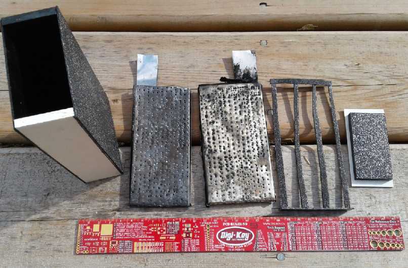 The components of a new Mn-Zn Oxalate cell with
"pocket" electrodes.
The components of a new Mn-Zn Oxalate cell with
"pocket" electrodes.
Apparently there weren't enough perforations in the "pockets" to conduct
the electrolyte freely, greatly limiting the current capacity in a cell
that
should have had at least a few amps and 25 amp-hours capacity.
(and later I'll add more electrodes to double that.)
In the middle of the month I put four of my solar panels
on the roof of the house (1000 watts). I thought of simply wiring them
to a grid-tie inverter. But that won't help in a power failure. I'd
rather have a separate system - especially if it can have good, high
capacity rechargeable batteries that last forever to store the power.
But I had a grid-tie inverter and I tried it out. It proved to put out
only 400 watts. It was advertised as, and said on it "1000
Watts". I think I was gypped. So it was effectively using only two
panels. I discovered it might take about 8 panels (2 KW, with 2 KW of
inverter(s)) to put things in reverse and stop the utility company
meter from racking up KWH on my bill, even on sunny days in the summer.
But when it got cloudy, the panels only put out 200 or 300 watts anyway
and the inverter was big enough.
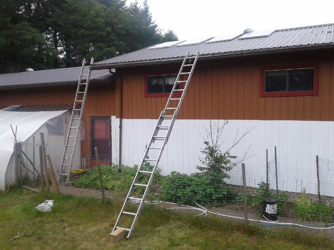 I climbed the left ladder, which was tied to a
hook.
I climbed the left ladder, which was tied to a
hook.
I hauled the panels up the right one with a rope.
(Setting them on the block of wood kept them from snagging under the
bottom of the ladder.)
I'm not happy that I still can't drive the Chevy Sprint
car on the highway. I started thinking about reluctance motors again,
with their good torque and very high RPM capacity. A reluctance motor
could be the best solution to outboard motor conversion as well as for
cars. Gas outboards gear down too much at the propeller shaft, so they
need a higher RPM electric motor and a reluctance motor should be
ideal. At first I decided to more or less copy the layout of the axial
flux, two
rotor design done in Guelph, Ont. in 2014. In addition to the Sprint
under-hood motor and an outboard that could make a small boat plane, if
enough power can be packed into a light enough unit, the "Electric
Hubcap" wheel motor plan (with a compact planetary or fixed gear
reduction) could be "on" again. And what about for a ground effect
craft? Surely the ducted fan design needs a higher RPM than a 'regular'
airplane propeller?
 Finally what I
took away from the papers, which I read more carefully than in 2015,
was that (a) the axial flux motor is the right layout and (b) - what
I'd missed - that it needs, bug, chunky iron magnetic components for
good force, not the fine stuff I made in 2015. (After all, it's much
harder to pull a big wrench off a supermagnet than a small
screwdriver.) Ideally for the car,
"slice of cake" coil cores might be 3 inches thick, and similar shape
"rotor poles" maybe half that thickness, with thick "back iron" behind
them all.
Finally what I
took away from the papers, which I read more carefully than in 2015,
was that (a) the axial flux motor is the right layout and (b) - what
I'd missed - that it needs, bug, chunky iron magnetic components for
good force, not the fine stuff I made in 2015. (After all, it's much
harder to pull a big wrench off a supermagnet than a small
screwdriver.) Ideally for the car,
"slice of cake" coil cores might be 3 inches thick, and similar shape
"rotor poles" maybe half that thickness, with thick "back iron" behind
them all.
I decided to try first the motor I'd made in 2015 with its
6
donut coil cores, but to match that with a rotor that used the same
iron powder cores as "rotor pole" elements. I found I could use the
same rotor by
cutting some bits out and inserting the cores, another good
simplification for a test. And it just might have the power to
run the outboard once it was working well.
On the 19th I took a day off and drove over the rough
logging roads to Rennell Sound on the west coast near the south end of
Graham island. The scenery was rugged and spectacular. The road rose so
steeply from the waterfront into the mountains that I had to drive the
Toyota Echo in first gear part of the way to climb out!
 Rennel Sound, opening to the west coast of
Graham Island (looking SW)
Rennel Sound, opening to the west coast of
Graham Island (looking SW)
 There was a camping area with a boat ramp
(looking NW)
There was a camping area with a boat ramp
(looking NW)
 and a little farther on, a "log op" - with
warnings to wait and follow a truck with a radio to avoid running into
logging trucks (you'll come off worst).
and a little farther on, a "log op" - with
warnings to wait and follow a truck with a radio to avoid running into
logging trucks (you'll come off worst).
This is a small island. You run into people you know...
A friend from Tlell who runs big machines got a job working here
later in July.
(looking W)
On the 22nd I finally decided to send an application to
ForesightCAC.com, "cleantech accelerator centre" in Burnaby BC. But did
I
really want to apply as a cleantech startup business? When after quite
some length I had finished filling out the online form which had many
involved business questions, I hit "send" and it said "failed". Then it
said "Prove you're not a robot", but there was nothing to click on or
type for that purpose. It said "failed" again, and I lost all my work,
which was considerable.
So the next day I telephoned. I had to leave a message,
and I said I had created new and 'better than lithiums' batteries and a
breakthough in bandsaw mill design among other things, and that "Now I
want to get them commercialized." That bit of grammar I stumbled
on is really exactly what I want. I don't really want to convert myself
from a talented inventor and product developer into a mediocre
entrepreneur. ("It's too bad we have to buy it this Canadian
technology from China. He had some great products but he sure didn't
know how to run a business!") Surely they must be in touch with
talented and enthusiastic entrepreneurs looking for products who would
be delighted to have some great newly developed cutting edge
technology(s), theirs to make and sell?
I managed to put this across quite well to the person who
returned my call. I hope they may manage to find a way to help get
things going.
I don't know how in our society that helps inventors to
put food on the table when patents seem to be worse than useless to
inventors (exactly who they were theoretically created for) and there's
nothing else, but
division of labor is a fundamental principle of advanced societies.
Perhaps there's something to be learned from the music industry where
those who write music as well as those who perform it and record it are
entitled to royalties whenever that music earns commercial
revenue. The composer/songwriter doesn't have to sell the rights to his
work for peanuts before someone will perform it and then perhaps it
becomes a top hit. Or defend it on his own budget in court against
those who've
used it without telling him.
On the 25th an e-mail from United Inventors' Association
in the USA said they are trying to have passed a new "Inventor
Protection Act". I applaud this effort! If successful inventors
can make a living, there will be more of them, and new products and
technologies to take us off fossil fuels.
To conclude this topic, on August 2nd I had an inspiration
as to how an inventor, even me, might after all get paid for his
discoveries and all the work that usually went into finding them. As
it's a brand new thought and as it involves others it may evolve
rapidly, so I'll leave off explaining it until next month. I've been
groping for something for 10 years, not to mention for another decade
before that. Maybe this is it.
26th: I note that I seem to be spending more and more time
writing - seemingly more than I spend on the projects these days. Does
writing more make up for not getting projects done? I've known what I
want to do on the bandmill for a couple of weeks now, but never seem to
get to it. Hmm. Not that nothing is happening!
Near the end of the month it didn't just get warm. It got
hot. There were much warmer days than any last summer, and lots of
them. The garden needed watering every day, or things started to wilt.
Temperatures approached or exceeded 30 °C in the shade. Smaller
creeks stopped
flowing. I actually appreciated having a real summer after the cool and
wet of last summer. But I know people over most of the northern
hemisphere this summer won't raise their eyebrows over our little "heat
wave" here. (It ended August 1st.)
 In the last 4
days of the month I got back to the bandmill. The cuts kept veering
upward in spite of the band being aimed downward by the self-adjusting
configuration. Finally on the 31st with a strong magnifying glass I
found a problem if not the problem: in addition to being dull,
the 'set' of the lower teeth was zero, no clearance at all. I did some
rough sharpening and tooth setting. That evening I finally cut a 6"
wide board, 13' long, that wasn't bad. And for once, without making any
adjustments either before or during the cutting.
In the last 4
days of the month I got back to the bandmill. The cuts kept veering
upward in spite of the band being aimed downward by the self-adjusting
configuration. Finally on the 31st with a strong magnifying glass I
found a problem if not the problem: in addition to being dull,
the 'set' of the lower teeth was zero, no clearance at all. I did some
rough sharpening and tooth setting. That evening I finally cut a 6"
wide board, 13' long, that wasn't bad. And for once, without making any
adjustments either before or during the cutting.
I finally added a cooling water system on August 2nd to
keep the
band from heating up and thus expanding and getting slack. With that I
cut a couple more boards even with the dull band. A new blade/band will
probably help a lot.
Reorganizing SDTC to meet real needs?
Early in the month I e-mailed SDTC with a link to my
uncomplimentary piece
about
them in the
last newsletter. I got the idea of writing my MP to suggest that SDTC
needs to be completely reorganized on a new basis since it doesn't do
what it was created to do - support sustainable energy inventions and
new product development - or else be scrapped altogether as being a
poor use of citizens' money. Then I started thinking that perhaps
several of us who were doing sustainable energy projects and getting no
support from them should get together and write to parliament instead
of just me.
Then I thought it would be even better if we can get a few
people together - a social sustainability design team - and work out
how we would set up the organization to meet the real needs for
fostering development of sustainable technologies. A plan sketched out
in
some detail for recommendation to parliament would probably be better
than just
criticism or even vague suggestions. My now rather remote location
works against organizing and meeting with people, unless it is done by
e-mail and perhaps conference calls.
Any takers on this? I welcome ideas and suggestions along
these lines,
especially from fellow inventors and product developers in Canada (but
also
anywhere), and especially from those with any sort of experience with
organizational structures, who think they might have good ideas for how
such an organization might ideally be put together.
And what does anyone think of the idea of having them run
a "Sustainable Technology Product Development Park" or even 2 or 3 or
more across the country? Look how we got the graphical user interface
and the whole workings of the internet from Xerox's "Park Pacific"
technology park. (Xerox didn't even understand what they had achieved
or know what to do with the results.) One technology park for a few
short years. What fabulous advances could we get from an ongoing one or
more than one?
This/these park(s) would hire creative people and guide
them as to what was to be created, instead of just waiting for whatever
off-target, high budget proposals drift
their way from well established corporations who meet some Procrustean
organizational criteria. They could hold patents on behalf of the
inventors, and being an organization of government instead of one
pretty defenseless inventor, should be able to successfully extract
royalties from all manufacturers both for the inventors and to become
a self-sustaining organization itself.
If a few people are interested it's not impossible we
might get
something useful done.
---
"Don't worry about people stealing your ideas. If your ideas are any
good you'll have to ram them down peoples' throats."
- Howard Aiken [Mathematician, physicist & computer pioneer]
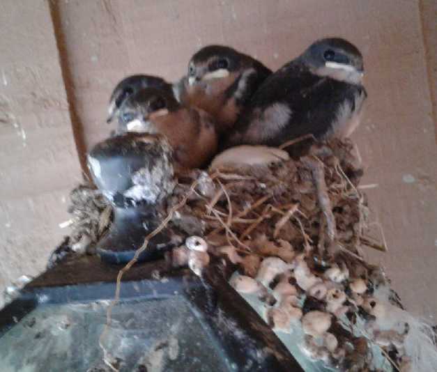 A nest of swallows messing up my front door
light.
A nest of swallows messing up my front door
light.
Just about ready to 'fly the coop' I should think (Aug 2nd).
In Passing
(Miscellaneous topics, editorial comments & opinionated rants)
Election Reform: Corrupting Influence
In Canada we were promised a new electoral system by the
present government if we elected them. Then they held meetings across
the country to help decide how best to set it up. I went to the one in
Victoria, and the one thing that was abundantly clear was that few
people who attended liked our current "illiterate's 'X'" single mark,
single ballot
system. When those meetings were done, they dropped it and will make no
changes. And apparently this has happened at least a couple of times in
the past
in Canadian history.
In BC we are now to vote on a new two-question
"proportional representation" system referendum in the next election.
While I'm not entirely happy with the choices being made available,
almost anything would be better than what we have. As soon as the BC
government announced it, a lawsuit was taken out to try to have the
referendum blocked, complaining about almost every detail. And Google
ads started appearing telling us that our present system is great and
"proven*", the new one (regardless of what is chosen?) would be a
disaster, that once we changed it we would be lost forever, and so on.
The .01% of corrupt, selfish, filthy rich and
anti-democratic people don't want a
system they can manipulate so easily and buy politicians to help them
get their way to be replaced with one that would make it hard for them,
and will spare no effort or expense trying to nip it in the bud. I
suspect they will
succeed again, as they have for over a century and most recently
federally. There are just so many apathetic people who won't take the
time to see and to think and perceive and make up their minds for
themselves, who will let their minds be made up for them by those who
squawk loudest - those with the money to hire PR firms and run plenty
of ads. (One of their complaints in the lawsuit was about the
campaign financing rules - because the government supplied a little
money to counter
their smear ad campaign!) Having given it no prior thought, all many of
these people may
remember at the voting booth when they are surprised to see these
questions actually there to vote on is all the negative ads warning of
doom and gloom should they vote for change, and reminding them of how
rosy the present system is - the one that keeps people rising up in
ineffective protest against its repeated unilateral acts, its giveaways
of public assets and its free-spending management of the public's money.
My own views on what sort of systems of governance might
be best are
laid out in detail at HandsOnDemocracy.org
* "Proven" only to be unfair to all and
socio-politically polarizing.
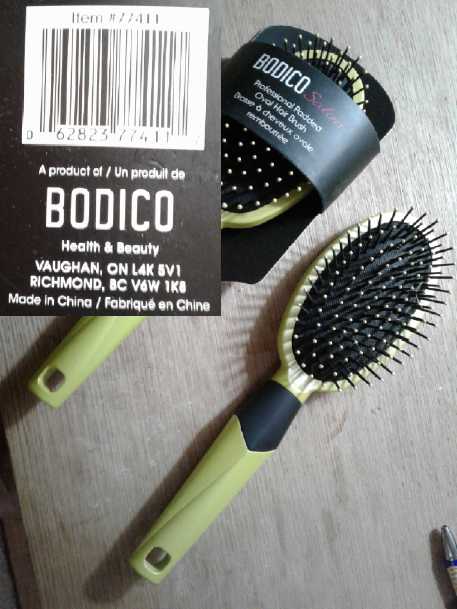
Keeping/Restoring Your Hair
 A couple of
years ago there was a piece of "click bait"
going around that showed a picture of a man brushing his partly bald
head with a brush, with the words something like "To keep or restore
your hair, do this daily." In fact this was complete within itself,
because brushing with a brush to stimulate the hair follicles is
exactly the right thing to do in (I believe the majority of) cases of
thinning hair or baldness as we age. Doubtless the makers were sure no
one would
believe it was so simple and would follow the link. (Or they may have
given some finer details in the links.)
A couple of
years ago there was a piece of "click bait"
going around that showed a picture of a man brushing his partly bald
head with a brush, with the words something like "To keep or restore
your hair, do this daily." In fact this was complete within itself,
because brushing with a brush to stimulate the hair follicles is
exactly the right thing to do in (I believe the majority of) cases of
thinning hair or baldness as we age. Doubtless the makers were sure no
one would
believe it was so simple and would follow the link. (Or they may have
given some finer details in the links.)
Now I've found a brush in a dollar store (4$ ... yay, we
now have a dollar store!) that's much
better than any other I've tried. I could feel the difference the first
time I used it and since. And after 3 or 4 months, I can see (in two
mirrors) that the thinning hair at the top-back of my scalp has gotten
thicker and if not "perfect" (yet?) no longer looks half way to bald.
And that's where I most felt that it had a very good stimulating effect
where other brushes I've tried (which I admit isn't very many) had
seemed pretty listless by comparison in that area.
I knew there was a difference between combs and brushes,
but I didn't realize brushes could be so markedly different. I don't
know what it is about this particular brush that makes it seem so good,
but here's a pictures of it. (I bought an extra to send to someone.)
A Hydrocortisone Cream Healing
Something I missed last month writing about applying
hydrocortisone cream... When I was maybe 12 I was trying to hacksaw
something. The piece wasn't held well and in the vibration the saw
suddenly jumped up and over as I cut, and cut into the back of my
thumb. Trying again brought a second slice. I didn't think much about
these at the time. Weren't they just cuts that would heal? But they
never did heal properly. The hacksaw teeth had ripped up the skin
pretty well and it hadn't gone back into place. They were always two
rough, scaly lines across the top of my thumb.
In rubbing hydrocortisone cream onto all the moles and a
couple of cysts, I started applying it to those rough lines too. They
seemed to get worse at first and irritated, then - after 50 years -
they healed over. They are smooth and just visible as slightly raised
lines. Wow!
(I never thought to take any "before" pictures, and
"after" there's nothing anyone would notice.)
The labels on hydrocortisone cream tubes all seem to say
to 'discontinue after 7 days'. But these sorts of skin healings - the
cuts and especially the cyst (never mind keeping the moles light)
required continuing
application over much longer periods of time.
Bad Grammar: "Mine" versus "Yours".
Somebody's "cutesy" but crazy idea from the 1980s(?) has
got parroted by all sorts of organizations. Even the government (CRA)
speaks of "your my account", a complete oxymoron in three words. It
bothers me that any organization should think it somehow enhances
customer or public perception of them or makes them seem friendlier or
more sophisticated to
perpetrate such confusing misuse of language. Since I wrote the
following
almost 20 years ago things have only got worse, and now I've had the
urge to dig it out of my e-mail records and reprint it.
---
Dear xx Bank VISA:
Our use of the words 'I' and 'my', and 'you' and 'your' in the new
cardholder's agreement which we sent you do not make sense to you!
It is common ground, implicit in grammar in every language that the
word 'you' refers to the person intended to read a document, and 'me'
or 'us' refers to the party which wrote it.
But we have elected to reverse the meaning of these common words,
which, of course, makes our cardholder's agreement difficult for you to
read. If you had written the agreement, there would be no need for us
to send it to you to read, would there? Instead, we there at VISA would
be the ones to have to receive it, check it over and see if your terms
were agreeable.
And we are not even consistent in our approach, since all the
correspondence we send to you, including the cover letter "Special
Notice To Cardholders" on the very same piece of paper as the new
agreement, says 'WE are writing to tell YOU', instead of 'YOU are
writing to tell ME'! Because if we did that, our letter to you would be
even more confusing than your cardholder agreement, would it not?
Who on earth writes our stuff, anyway? I should be shot!
You would be greatly relieved if we chose to restore these words to
their proper meanings in the future. Thank us very much.
Mine truly,
VISA cardholder
Peace Between USA and Russia
In mid July, US president Donald Trump met with Russian
president Vladimir Putin in Helsinki, Finland. Trump said relations
between the two countries 'have never been worse', and that that was
thanks to stupidity in Washington. He wanted to improve them and to
have peace between the two democratic republics.
Trump was attacked for this, not by Russia but by his own
country. He was accused of "being in Putin's pocket" and "what did
Putin have on Trump that he could be blackmailed in such a way?" One
malcontent said Trump's promotion of peace between them was "the
highest treason". The funny thing is, Trump said before the meeting
that regardless of the outcome that is what would be said of it. And
that no possible outcome would be good enough to satisfy these critics.
But one notable person said Washington had "criminalized diplomacy".
The "deep state" - largely the civil service bureaucracy
including the military and the many security agencies, as well
"cross-connects" from the largest corporations - that holds real
power hidden away in private from public scrutiny isn't used to having
a president who, whatever his faults may be, is trying to make state
policies in public and apart from their lies and conniving back room
deals to
keep the military-industrial-banking-oil-monsanto-pharmaceuticals
complex in business and receiving way over 50% of the US national
budget, regardless of the needs of the people and the potential for
peace in the world. They will discredit him with any lies and
unfounded insinuations they can think of, and they dearly wish someone
would
shoot him and get him out of their way. In fact some of them are
actually advocating it - real treason not only against the peoples'
chosen leader but against democracy itself. And they will feel the same
way about any president who follows him who has the temerity to try to
lead the nation instead of to follow their dictates.
Dwight D. Eisenhower warned that the need to maintain a
large "military industrial complex" after world war two was itself a
grave threat to American liberty. Liberty and equality minded John F.
Kennedy was shot to get rid of him, apparently by the mafia but with at
least complicity by federal agencies. (See "Oswald's last phone call"
on youtube.) Robert Kennedy was shot beforehand to prevent him from
ever taking up the reins. Then Richard Nixon was thrown out. Why? After
being a perfect "deep state" stoogie for several years, Nixon got fed
up. He ended the Vietnam war, Accorded China long overdue diplomatic
recognition, and started nuclear arms limitation talks with the Soviet
Union. That was why the Watergate manipulations, in which he had of
course played a part, suddenly came to light: deliberately to arouse
public indignation to get rid of him. Dr.
Paul Craig Roberts says they repeatedly tried to block Ronald Reagan in
most everything he tried to do in the 1980s, including rejecting or
stalling on approval of his chosen appointees (as with Trump),
"Reaganomics" (of
which Roberts as assistant treasury secretary was the co-author), and
most especially of his trying to end the cold war. After his second
election Reagan became senile, and instead of promoting the
vise-president it was covered up for the rest of his term. What a
perfect president to let them have their way with no argument! (The
senility was just fortuitous... right?)
I know Nevil Chamberlain once said this and was quickly
proven wrong, but personally I don't believe any important nation in
the world today wants war... apart from the US 'deep state' actors. If
it was up to them, the world could well be a desolate radioactive
wasteland by
now. Unfortunately these types of people too often get their way. They
won't take "NO!" for an answer and will keep trying different tactics
until they do. But
here, finally there is just too much at stake to let them and they
haven't.
Which brings up another topic... One of the worst problems
(besides overpopulation) is that our justice systems are so gutless (if
not corrupt). Some of the worst of the selfish people in government and
in corporations who commit egregious crimes, predating on and working
against their own people year after year and decade after decade should
be given an overdose of morphine and be peacefully removed from the
planet to get them out of high places and to demonstrate that society
will not give in to crimes of betrayal against itself that prejudice
the whole future of civilization and freedom. It's not that "jail is
too good for them": it's that they will simply continue to predate
whenever they are free to do so and that many of them can call on their
friends or henchmen to bribe, threaten or do away with those who are
causing them trouble even while they are in jail. Someone is going to
die: should it be the troublemaker, or whoever opposes the
troublemaker? Gutlessly allowing the latter course to occur leads to
problem after problem and often victim after victim since the source of
the trouble is still there.
Just for one familiar example, how different might history
have been if Adolf Hitler had been executed for attempting to violently
overthrow democratic government in the "beer hall putsch", instead of
simply being jailed for a time? There are many and various other
examples of ways in which the world has been markedly damaged by single
individuals who should have been permanently stopped, but the
consequences of that one particular failure to act resolutely at the
critical moment are the most stark. Civilization was shaken to its core
and tens
of millions died.
The only two ways people are safe are (a) knuckle under to
unreasonable demands and conditions - and ultimately live in a
totalitarian dictatorship or (b) eradicate the predators. The only way
the network of associates and henchmen won't bribe or threaten or
murder is if their boss is no longer there to give the orders and to
pay them and protect them from the law themselves. Not there to ensure
there are no investigations into briberies or threats, or that the
suspicious death of an opponent will be deemed a "heart attack",
"suicide" or "accident" likewise without any investigation. How many
judges, prosecuting attorneys, witnesses and others have been murdered
by those they sent away for more limited punishment? It makes
obvious sense: only one person, the predator, is killed instead of
potentially
numerous innocent and usually upright victims who try to stand up to
him, know too much or just get in the way. We will not have social
stability, much less sustainability, while people are, with good
reason, afraid of violence.
The media is now owned and paid for by the same "deep
state" that holds the real power hidden away in the back rooms and they
trumpeted this "Trump's treason" nonsense to the American public. I'm
not sure how many are still buying it. But no major station or network
(all owned by the same 5 or 6 people) will depart
from those narratives.
Interviewees (and even news announcers) saying the wrong thing have
been known to be cut off in mid sentence as the network "has technical
difficulties". The CIA has an agent now in every major newsroom to vet
what stories must, may or can't be aired.
But they haven't been able to
stop the internet. Trust in the western mainstream media is more and
more being eroded as more and more people start to realize they're
being fed crap that doesn't match facts and leaves major issues
and events uncovered. And as opposing information, opinions and
viewpoints from many lands present themselves on the internet. In spite
of accidental or deliberate misinformation here and there, a
different and more coherent picture of events is starting to be
discerned by
increasing numbers of people. The 'establishment' wages real, serious
war on real journalism as exemplified by The car booby-trap murder of
Michael Hastings and Hillary "Can't we just drone strike him?" Clinton
regarding Julian Assange as well as the whole Wikileaks organization.
They seem to have cowed Equador into agreeing to turn Assange over to
their tender mercies.
Russia was once the home base of communist zealots who
thought the world would be a better place if they ruled it in
accordance with their ideology and who thought any and all means to
achieve that end including violence and war was justified. They ended
up dictating to the whole of eastern Europe for decades. (And if Victor
Suvarov is right, the rest of Europe and perhaps the world got off
lucky.) Today
Russia is a democratic republic where there is probably more freedom
than in North America, which since 2001 is rapidly becoming
increasingly unlivable by government decree. (Toronto psychology
professor Jordan Peterson [see on youtube] has attacked one
Canadian 2016 bill in particular as giving the government sweeping
power pretty much to prosecute - persecute - anybody they decide isn't
being "politically correct" or is saying things someone disagrees with
even if it's an honestly held opinion. People have become afraid to
voice disagreement about anything, however disagreeable, for fear of
official retaliation without recourse: fines, loss of job, loss of
rights, eg, to fly or
leave the country, even jail. Freedom of speech and freedom in general
is under increasing assault.) Even Iran, another special target of
American venom, has an elected president, who was peacefully changed
without so much as honorable mention or a hiccup in the "Iran needs
regime change" rhetoric.
Get over it!
Look to home for where "regime change" is really needed.
We have democracies. We need better communication channels with our
elected representatives in order that they do our collective will
instead of that of corrupt special interests or vocal minorities. And
we need to better know who we are really electing. What have been their
past actions and activities? Are they capable, experienced, honest,
sincere? Or are they a social predator in disguise? Knowing like Hitler
how to present themselves in public as being good and reasonable,
knowing how to tailor their "beliefs" and "principles" to
the audience, makes them more dangerous unless they are exposed, which
to date rarely happens.
And whatever most people who aren't themselves a special
target of some social predator may think today, we desperately need to
have a death penalty and we need to use it on those who prey on us all
and it has become a long continued, habitual pattern for them or a
present menace to the future of society. Permitting social predation
sets the stage to wreck the future. The tentacles start spreading
pretty soon after the unpunished, uncorrected crime, and encourage more
and more and larger and larger such crimes. (Anybody remember what
happened to Hitler after he got out of jail? Did it reform him and he
went about doing good? He just changed his tactics that hadn't worked
to ones that did.)
We are all tacitly or indirectly responsible for decisions
by leaders. Employees and shareholders of corporations are at least
tacitly complicit in immoral decisions made by management. When the
great majority plays their part, each person helping to prevent wrong
things including the wrongs behind the other wrongs, or to "regime
change" what has already gone wrong, we will we have peace and
stability - and perhaps even continuity and social sustainability.
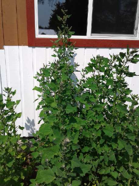
Quinoa as an emergency food grain? - Salal - Vegetable Gardening
Quinoa, mid July. By the end
of the
month it was taller and bushier, and buzzing with pollinating
insects, flowers with seeds forming and growing everywhere.
 Potatoes is still the easiest way to get calories from a
garden. If I plant wheat here in a large enough patch to be
useful, that would be too large for a tall fence and the deer would
probably eat it all. But here's something else where wheat (etc) may be
impractical for a home gardener. A couple of years ago I grew just 5
plants of quinoa in my garden in Victoria BC. They grew tall and bushy
and produced a whole jar of seeds. This year I'm trying a larger patch.
Potatoes is still the easiest way to get calories from a
garden. If I plant wheat here in a large enough patch to be
useful, that would be too large for a tall fence and the deer would
probably eat it all. But here's something else where wheat (etc) may be
impractical for a home gardener. A couple of years ago I grew just 5
plants of quinoa in my garden in Victoria BC. They grew tall and bushy
and produced a whole jar of seeds. This year I'm trying a larger patch.
Only one of the 6 seedlings planted early indoors survived
outdoors. I planted a bunch of seeds in the garden - twice - and for a
while things looked rather sparse and unpromising. I even planted beans
and things between the rows in case the quinoa didn't do anything. The
one from indoors is still the largest, but others finally started
catching up, and in spite of some being eaten by slugs when they
were small, it now appears they are pretty crowded (just one notable
bare spot could have used another plant) and I should have followed the
spacing guidelines or thinned them. But it looks like there'll be a
good crop.
Since quinoa is rather grainy unless soaked, on the 24th I
tried grinding up some into a flour in the coffee grinder. It's
probably more
like rice flour than wheat flour. It added some grittiness to a cake
and cookies, but not so crunchy as the whole seeds. A real flour mill
would doubtless make it quite smooth.
Salal, Aug
1st. Hmm... Picking season is hardly starting...
but these ones growing near a creek have some notably bigger berries,
already ripe.
Maybe I should water mine?
 I also
(finally) read up on salal,
a berry native to the west
coast of North America from about Washington state north to the
southern islands
of Alaska. It didn't seem to be related to anything, but I discovered
it's a member of the heather family and has been imported to the UK and
Europe. It's very plentiful in my neighborhood, especially in an area
of my field and by the highway. Stems with leaves are very popular in
floral
arrangements. It has a small blue-black berry that makes good pies and
jam. Being so small, they're as tedious to pick as wild blueberries,
huckleberries or saskatoons; maybe more so. Then usually you have to
pick out bits of stems and petals before using them. So far it hasn't
been available
commercially, but after picking saskatoons wild in Edmonton over half a
century ago and hardly seeing them since, I never expected to see them
available commercially either. (The wild ones are bursting with flavor.
I've been unimpressed by the commercial offerings except the last jar
of commercial saskatoon jam I had was very good.)
I also
(finally) read up on salal,
a berry native to the west
coast of North America from about Washington state north to the
southern islands
of Alaska. It didn't seem to be related to anything, but I discovered
it's a member of the heather family and has been imported to the UK and
Europe. It's very plentiful in my neighborhood, especially in an area
of my field and by the highway. Stems with leaves are very popular in
floral
arrangements. It has a small blue-black berry that makes good pies and
jam. Being so small, they're as tedious to pick as wild blueberries,
huckleberries or saskatoons; maybe more so. Then usually you have to
pick out bits of stems and petals before using them. So far it hasn't
been available
commercially, but after picking saskatoons wild in Edmonton over half a
century ago and hardly seeing them since, I never expected to see them
available commercially either. (The wild ones are bursting with flavor.
I've been unimpressed by the commercial offerings except the last jar
of commercial saskatoon jam I had was very good.)
If you suspect there'll
ever be food supply problems, the
time to learn how to garden vegetables is before it happens. A sort of
insurance, but it does take a certain amount of know-how. It's easier
to expand if necessary by already knowing what's needed than to start
learning to recognize a weed from a cabbage seedling when hunger is
around. And you'll need some basic seeds and supplies in advance too.
And
of course you always get the best, freshest and most nutritious
vegetables when
you grow them. Commercial frozen peas don't have the flavor of 'real
ones' fresh from the garden.
And various things to learn are different in different
areas. Despite still being on the coast I note that the bugs buzzing
around the flowers here are much more like the ones in Edmonton AB than
those of Victoria BC. (must be a latitude
thing?)
And slugs were never a real pest in town in Victoria. I never bought or
needed "slug
bait" there, but here they can eat whole rows of seedlings and I
lost lots of crop "in the bud" last year before I caught on, and still
some
this year. (Must stock up on slug bait in advance of any supply
disruptions!)
Helping Ourselves by Helping Underdeveloped Countries
I've always thought it was irresponsible of all those
undeveloped countries to keep having so many children when they can't
feed them all. In the "developed" nations we have been
having children under the rate needed to maintain the population
for decades now. This
problem continually comes to light as people from more crowded places
with few opportunities keep flooding into the lands that should be
enjoying a great standard of living for everyone, keeping them pressed
to support growing populations. This influx of mostly unwanted
immigrants is reaching crisis proportions. We are everywhere hitting
the limits. We can't maintain our quality of life as long as the
population keeps growing, especially when the migrants don't have our
culture and values or even language, and so are a drain rather than a
benefit for quite some years after arrival. Opportunities even in the
developed nations are shrinking to the point of vanishing especially
for
the young, and inequality has become egregious.
Now it has come to my attention that it's not that the
undeveloped regions want all those children. But people
everywhere do want sex. The problem boils down
mainly to just one thing: in the more developed nations we have ready
access to birth control products. In the less developed places they
don't. So we don't have babies unless we want them, whereas in the more
primitive places the babies keep coming, wanted or not.
Instead of sending food or other immediate material aid,
we would surely do ourselves as much as them a much greater service by
offering to send free birth control products so the people there can
choose not to have more children than their land can support. Solving
the refugee and migrant problem is worth the price - especially when
the aid won't simply be fostering a larger and larger population who
then need more and more aid, and people who are compelled to migrate to
seek meaningful lives.
South Africa: No genocide after all?
In a later news article, the president of
South Africa seems to have backed off on his earlier "get rid of the
whites" stance, saying that they weren't out to kill off the whites and
other minorities after all. Hopefully and likely some voices of reason
even from within the black community have induced or forced him to
change the attitude of a few months back, and hopefully this improved
attitude will continue. Perhaps they look next door to Zimbabwe where
the whites were killed or driven out and the country has become
primitive and barbaric. "Is that really what we want?" Still from what
I've heard South Africa is a relatively violent place and I'm glad I
don't live there. Doubtless so are the 15% or more of the entire white
population which has already departed.
More on Bankers Creating the Money Supply
"Banking was conceived in iniquity and born in sin. ... Bankers own the
Earth. Take it away from them but leave them the power to create money,
and, with the flick of a pen, they will create enough money to buy it
back again.
"Take this great power away from them and all the great fortunes like
mine will disappear and they ought to disappear, for then this would be
a better and happier world to live in.
"But, if you want to continue to be a slave of the bankers and pay the
cost of your own slavery, then let the bankers continue to create money
and control credit."
- Josiah Stamp, director of the Bank of England, 1928
Just how much longer are we going to let this admitted
pyramid scheme continue? Why don't nations simply say "Our treasury
department will print whatever new money is needed, and the public then
won't owe it - with interest - to anyone." Admittedly the bankers kill
or try to kill any national leader who tries this approach and perhaps
it's small wonder our politicians seem to have no courage. As I
understand it Argentina was letting its provinces print their own money
some years back and having an economic boom, then the IMF stepped in
and told them the nation had to trade in all these local currencies for
national currency (wait for it...), borrowed from the IMF. I don't know
what coercion was used but it probably involved some pretty serious
threats. No such prosperity making alternative was to be permitted.
Today Argentina's currency is inflating away and the nation is in a
depression again.
We need people everywhere in lesser places too to say
"Whatever happens, even to our leader, the new money policy will still
be law and the nation will never again borrow money created out of thin
air by a bank instead of creating it itself."
What is News?
On TheWeatherNetwork.com was a headline about a teen
infested with hookworm parasite while playing on a beach. Such a thing
catches our eye. But why? And why include such a story in national news?
Where was it? Most likely far, far away from you or I.
Unfortunate though it was, just for example, millions die annually of
cancer, and in our own neighborhoods. Wouldn't it be more useful to
talk about how you can cut your chances of getting cancer at least in
half by getting either vitamin D or some sunshine daily or at least
very frequently? Cite some study or a bunch of them - they all say it.
That gives people good news and something positive they can do, instead
of just making them needlessly anxious over something that virtually
never happens to anyone. (Okay... just had to look... it was Memphis
TN, and he didn't just walk across something bad in bare feet, he had
been buried by friends in the sand, where the hookworms apparently
lived. (I bet it looked dirty, too.) And TN is inland, so it was a
freshwater beach, not ocean. I.E: this will never, ever happen to me or
you.)
And if one wanted to focus on bad news, there was plenty
of more newsworthy bad news without dragging in such drivel.
Double Agent Strzok
Hah! He was supposedly an FBI agent, now it seems Peter
Strzok was actually a CIA agent planted in the FBI! Impersonating an
FBI agent is a federal offense. So is espionage against the government,
and so is CIA activity within the USA. So is he classed as a foreign
spy or a domestic terrorist? How many more are infiltrating how many
departments? Does the FBI infiltrate the CIA? Does the IRS know Strzok
is collecting two paychecks? Who should investigate this clearly
illegal activity? Does the IRS infiltrate the CIA? Does the CIA
infiltrate the DHS? Is the snake eating its own tail?
"in depth reports" for
each project are below. I hope they may be useful to anyone who wants
to get
into a similar project, to glean ideas for how something
might be done, as well as things that might have been tried or thought
of... and even of how not to do something - why it didn't
work or proved impractical. Sometimes they set out inventive thoughts
almost as they occur - and are the actual organization and elaboration
in
writing of
those thoughts. They are thus partly a diary and are not
extensively proof-read for literary perfection and consistency before
publication. I hope they add to the body of wisdom for other
researchers and developers to help them find more productive paths and
avoid potential pitfalls.
Electric Transport Projects
ARM Reluctance
Motor & Unipolar Motor Controller
I was working on my "ARM" (Axial flux Reluctance
Motor) and "unipolar motor controller" in 2014 and 2015, then other
things
caught up with me and I stopped. Now
having spent some months to get new chemistry batteries more or less
created and 'tamed' so to
speak, I thought
that getting a good reluctance motor and controller working would give
the best of everything:
* It would in and of itself be a superior motor, and it would
(presumably) provide a
motor controller for various reluctance motors.
* It would provide a platform for trying out the "permanent magnet
assisted" motors idea, since I already had some magnets the right size.
* It would get the electric outboard going without trying to solve the
cooling problem of the present Electric Caik BLDC motor. And it
would be better because it could exceed the RPM of the original
gasoline engine removed from any outboard where most electric motor
RPM.s limit boat
speed.
* It would provide a motor to get the Chevy Sprint - and by extension
most any light car - on the road and on the highway, efficiently with
simple
fixed ratio gears.
Note: I have recently found there are two entirely
different types of "PM assisted" reluctance motors. In one the
permanent magnets are in the coils as previously described. In the
other they are in the rotor. I haven't come to grips with how this
second type works yet myself.
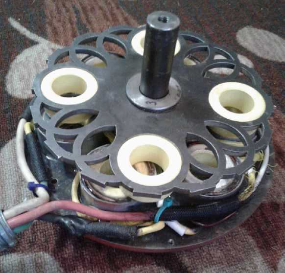
So I decided to locate the components of the project and
pretty much start again, but with certain things already made. I would
try out the same unipolar motor controller and the same motor stator,
but with a new "more conventional" reluctance rotor on the motor. My
attempted
"flower" pattern rotor matching the donut coils ran, but it was
nothing like it was intended to be,
perhaps at least partly because when made, the "rings" didn't
seem to line up quite the same as when I had cut them out of cardboard
and simply set them in place for a rough estimate. As it was, there was
some
braking force as well as the forward force at certain points of
rotation.
In some reading I found out also that the rotor poles each
need way more iron for the stator to attract. That's probably the
biggest key to getting a motor with good torque. Changing the toroidal
coils to rectangular or pie shaped ones to
maximize the magnetic attraction along a rotary line of force would
also be very useful.
But the first question was, where? My electronics lab here
is tiny. The big workshop seems not very suitable. But it's summer and
the workshop is probably the place until it gets too cool to work out
there - if I can figure out how to set up a good workstation somewhere
- and get to the project.
I started by
freeing up some space by the only wall without shelves built in in
front of it - by installing the solar panels leaning against it.
Then other things caught up again. By the 16th I
thought I had decided to start afresh on the motor and just use the
controller. I
would look up a few more reluctance motor projects by others on line,
and perhaps find a pattern of coils and rotor design that "meshed"
really well together. Donut coils were great for BLDC motors, but
without supermagnets on the rotor, merely soft magnetic material,
reluctance motors require far closer and more exact magnetic coupling
to get high torque - or even "good" torque. Practically everything that
could contribute to that coupling seemed worthwhile incorporating into
the design.
In the evening I tried to find more info on line but I
wasn't finding much besides things I already knew. Finally I thought of
the two papers on axial flux reluctance motors I'd downloaded in 2015,
and finally I found the folder I'd put them in.
---
The first paper was (Sorry, I don't have the URL) [Hmm,
extra words appeared when I copied and pasted the text of the title and
authors!]:
Preparation of a Formatted Technical Work for the ICEM [the above words are not visible on the page]
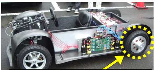
A Design of Axial-gap Switched Reluctance Motor
for In-Wheel
Direct-Drive EV
by J. W. Haggle,
L. L. Grigsby [the above names aren't
visible on the page] Tohru Shibamoto,
Kenji Nakamura, Hiroki
Goto and Osamu Ichinokura Elec. and Comm. Eng. Dept., Tohoku University
This motor was very high torque, but it had a problem that
the torque dropped off much too quickly with RPM above 200. The graph
stopped at just 800 RPM. I thought reluctance motors were supposed to
be able to easily spin really really fast? What about 8000 RPM? Was
this steep torque drop-off inherent, or was it programmed in as part of
the operating characteristics they desired for their specific "in
wheel" motor
in their specific test car? (I confess I don't think I'd want to be
doing highway speeds in it. Aviator goggles required!)
OTOH, they actually built and tested this motor. It turned
out the other
paper from U of Guelph was just a theoretical study.
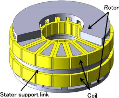
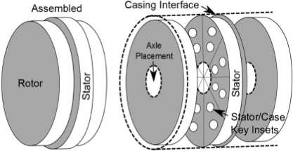
In what they actually
built, their "stator support link"
looked in the diagram like a solid steel plate with a coil above and a
coil below. If that was
so, wasn't it just two mirror image motors with a common shaft? Then
wouldn't a single motor with one rotor perform just as well?
---
The other
paper was:
Machines 2015, 3, 27-54; doi:10.3390/machines3010027
machines ISSN 2075-1702 www.mdpi.com/journal/machines/
Article
A Novel Approach to the Design of Axial-Flux
Switched-Reluctance
Motors
Tim Lambert *, Mohammad Biglarbegian and Shohel Mahmud
School of Engineering, University of Guelph, Guelph, ON N1G 2T6,
Canada;
OPEN ACCESS
Both papers said that with reluctance motors, axial flux
gave best performance. Their motor was pretty similar, but with fewer
coils
and
apparently a different scheme for attaching the stator. (Some things
weren't clear and I started thinking of the "Stator/Case Key
Insets" as perhaps being slippery plastic bits that the rotors would
hit during vibration and jarring suspension changes. But that's
probably wrong. I don't have a clear picture in my head of how
they intended to attach the stator. A problem with a theoretical study
where nothing was actually built is that they may not have thought it
through completely themselves.)
---
Both motors had two rotors, one on each side of the stator. There,
apparently, was a chief key to maximizing torque, more or less doubling
it over one rotor, as well as supposedly improving energy conversion
efficiency. Each stator
coil core was a pie shape with the edges radial to the axle. The rotor
poles of this motor appeared to be similar, but of course there were
fewer of them. All very well, but...
With a rotor on each end, it looked to me like it would be difficult to
mount the stator coils. (Gosh, just like the axial flux generators with
two rotors!) The Tohoku motor showed a single stator in the initial
diagrams, but apparently when built was made pretty much as two stators
with a plate ("link") between them, which was required for sufficient
stiffness to handle the calculated magnetic forces. Would it not
then perform just like two single rotor motors? That would certainly be
easier to
make and to mount, even if it had to be a little bigger and or be
geared down more.
I thought of an alternative: putting "horseshoe"
electromagnets around the
outside, whose arms would equally attract the top and bottom the poles
of a single central rotor. But it would need very fat "arms" going to
the stator to carry the flux. These authors seem to refer to that as
"the double stator" layout. Their main complaint was it took extra
volume.
At first, knowing so much (ie so little) about all this, I
decided that the best thing to get the highest torque was to more or
less copy designs that worked. The axial flux seemed to be superior,
but the two rotor design seemed superfluous or difficult. I e-mailed
the authors of the paper in case any of them might still be reached at
U of Guelph. But somehow I hadn't realized at that point that theirs
was merely a
theoretical paper and nothing had been built. There was no reply. And
only the Tohoku one had
actually been made and tested.
What about the number and size of the active
components? I figured that the fewer poles there were, the higher the
RPM could likely be, so 6 or 8 coils should be better than the large
number in the Japanese design. If I made it 8 like the Ontario design,
it would need a 4-phase motor controller instead of 3-phase and I'd
immediately have to do a new motor controller as well as the motor. I
expect a microcontroller based motor controller is the way to go, and I
may end up doing 4 phases if I don't like the behavior of the 3-phase
motor, but for now the working controller, which I also wanted to test
further before starting a new one, made 6 coils the simple choice.
Also, the fewer poles, the fewer the magnetic reversals
for a given RPM, and so the lower the hysteresis losses in the rotor.
(Remembering that I already tried like poles and to avoid magnetic
reversals in 2015, and the motor had even less torque. That could
change with two rotors, with the flux going through the axle, but for
now I'll assume it won't.) Note that only the rotor poles reverse
polarity, not the stator coils, which already avoids the bulk of the
hysteresis losses. This is another advantage of the simple 3 phase
design: the coils have no reason not to actuate in pairs, the same
pairs each time, and so polarity doesn't matter.
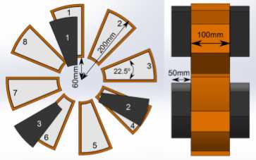
I started thinking about actual dimensions and placements:
Phases: 3 (6 coils, 4 rotor poles)
Stator Thickness: 3" --- 1"
made enough flux depth for coils for supermagnet rotors, but we need
much more flux with just a steel rotor.
Without going completely nuts, why not
greatly increase the depth of the field?
Rotor Salient Pole Thickness: 1/2" plus rotor disk --- (Or should
it be thicker, in keeping with increased depth of field?)
Rotor/Magnetic Diameter: 7" --- We get to go very high RPM, so why use
a very large diameter? Keep it compact.
7" should do it? (Or maybe 7.8"/200 mm, and
then I can use Princess Auto "brake rotor disks"?)
 I
found
that
the
U of Guelph motor said 100 mm stator thickness
(4") and 50 mm rotor thickness (2"). The diameter is a very large 400
mm (16"). In spite of intending a "wheel motor", it seems a bit of a
monster
at 40 Kg. I wouldn't want that as unsprung weight on my car
wheel!
I
found
that
the
U of Guelph motor said 100 mm stator thickness
(4") and 50 mm rotor thickness (2"). The diameter is a very large 400
mm (16"). In spite of intending a "wheel motor", it seems a bit of a
monster
at 40 Kg. I wouldn't want that as unsprung weight on my car
wheel!
Since my plan is just a motor to mount anywhere, not to go
inside a wheel, it can spin higher revs with less torque and doesn't
need to be as big. If I maintain the proportions with 3" (75 mm) thick,
the rotors poles should be 1.5" (37 mm) thick. Thus the motor is
already 6" thick (or 4.5" with one rotor. But if I use an effective
diameter of 200 mm instead
of 400, it has just 1/4 of the interface area. That shouldn't
going too small if it's geared down enough - eg, 4 times more.
BTW, the idea of allowing the rotor to move off center compared to the
stator so it can handle wheel suspension movements didn't work for me
in 2008. Instead of turning the rotor, the stator jumped around
wildly in front of the rotor (car wheel) with the magnetic forces. I
had to put in a
"lazy susan" bearing as a thrust bearing to keep them on a common
center. (how
little I knew about mechanical components and supply sources back
then!) I didn't see that this issue was dealt with anywhere in this
theoretical paper. How well did they really know what they were doing
as far as making a real, practical motor? All the forces in this motor
are attractive, none repulsive, and the stator is much heavier. Those
things might make a difference, but I have my doubts.
The control scheme, position sensing and flux paths are
markedly simplified in the 6 coil, 4 rotor pole design compared to 8
separate coils individually driving 3 rotor poles. For one thing the
coils simply come on in pairs making for just three phases instead
of eight separate activations. When the coils come on in pairs
with one magnetized 'north' and the other 'south', there is an even
strength flux path across the rotors between the two driving coils and
the four driven poles - two on each rotor at opposite ends.
I'd rather have a stationary case than a spinning one,
with only the shaft spinning externally. It seems to me a 3" thick
stator whose outside is the outside of the motor will also provide more
outside surface for cooling. Maybe some heatsink fins around the
outside? OTOH, if the outside of a spinning case was centrifugal fan
blades with the air drawn in through the ends by holes in the rotors,
that might do a good job of keeping the motor cool too. Then the stator
coils, and the motor itself, would have to attach to the
stationary center shaft.
There was no reply from any of the U of Guelph team. The
lead author, Tim Lambert, seemed to have moved to a company selling
BLDC motors and equipment for scooters, etc. So it didn't sound like
they had made a real success of the axial reluctance motor themselves,
or they'd be for sale. (Well, if they never even built one!...) Here's
a last table from their paper:
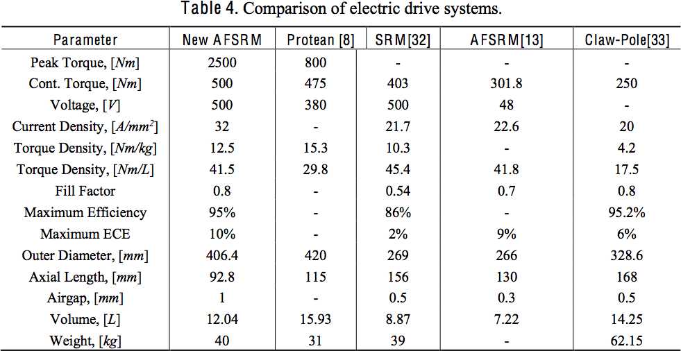 The motor referenced as [13] is the one from
the Tohoku University paper (First paper above).
The motor referenced as [13] is the one from
the Tohoku University paper (First paper above).
It appears only the Japanese weren't using an insanely dangerous
voltage.
Note: Current density
How is it I've been making motors for so long and yet paid
so little attention to this parameter? How many amps does one want to
ram through what size of wire, as in the table above? Perhaps it's just
that I'd never taken note of what others were spec'ing, as in the table
above.
Of course in the absence of room temperature and above
superconductors, the more the amps, the hotter the wire will get.
[what's happened to those, anyway? somebody's research was getting
results a few years ago. For the first time ever, they had to raise the
temperature to find the superconducting point.]
My Electric Hubcap on the Sprint car, with the Kelly
controller, occasionally used up to 150 amps. It got hot fast. The
cross section of the #11 AWG wire I used is 4.17 sq.mm. If I restricted
current to the figure spec'ed for the Japanese motor, 22.6 amps/mm^2,
I
should have limited the current to 94 amps. 94 A * 36 V = 3400 watts
or 4.5 HP. (It still would have got hot pretty fast, I think.) I think
the U of Guelph team were unrealistic spec'ing 30 amps/sq.mm - that's
about like my 150 amps that got so hot so fast.
If I want the reluctance motor to have more horsepower at
the same 36 volts, it would appear I should wind two strands of #11, or
equivalent to keep it from getting too hot. As it is, the one I have
now with a single strand at 24 volts should be limited (again using the
22.6 amp figure) to (22.6 A/sq.mm * 4.17 sq.mm) * 24 V = 2260 W or 3
HP. And that's only if it has quite good cooling.
One can balance by putting coils in series or parallel. If
instead of having two coils of 21 turns (2 layers or wire) in series,
it had two of 42 turns (4 layers) in parallel, each coil would handle
94 amps current, total 188 amps. That's theoretically double the
available current and horsepower. (And it looks like there would
actually be enough room for the extra wire.) Of course, with four
layers of copper wire on each coil instead of two, each coil will be
harder to cool, so one may have to limit the current to a lower value
and the overall improvement, except perhaps for short burst capacity,
may be more limited than expected.
Or I could use two coils in series with ~32 winds (3
layers) instead of 21 and change it to 36 volts. There again is the
theoretical 4.5 HP but probably somewhat less than that in practice.
Back to the old Motor, with a new Rotor
Well, double RPM makes up for half the torque via a
different gear ratio, so if there was actually little or no real
advantage to
having double rotors in practice, the stator plate I had made in 2015
should be as
good as any other. So before I got too carried away, I decided to try
the
previously unused four pole rotor I cut in 2015 with the original
stator, just to see what I might learn. On the 25th I found some
various washers and spacers that let me put that rotor in. That just
left mounting the optical interrupters. The spacings for those would be
completely different.
Then I thought about how fat the rotor poles were in the
other motors, and how at least in the Guelph design, the poles were the
same size and shape as the stator coils. A big chunk of steel is harder
to pull from a magnet than a small one. That made the thin 3/16" steel
of my rotor seem rather pathetic. In fact, whatever the other failings
of the 1/4" thick "flower petals" rotor, too little iron in the poles
was
doubtless the biggest one. If I was to use this motor with its 2" O.D.
round coil cores, probably what it should have for rotor poles was
something like 2" steel hockey pucks, at least 1/2" thick. That might
actually make a motor that would run the outboard. ...What about
using four of the actual iron powder toroidal cores? I wasn't sure the
rotor needed to be made of laminates, but these would be even
better than laminates. (Not physically stronger for high RPM.s, though!)
The diameters said these "pucks" would stick out slightly
past the outside of my rotor. So the next question was how to mount the
optical interrupter parts. It might be necessary to cut some pieces of
sheet metal and bolt them onto the outside of the rotor to make
"solids" and "gaps" or "slots".
Maybe I should use a different rotor after all?
In fact, it just might be worth getting another special
one cut for me at Victoria Waterjet.
And in the stator, I still have the cylinder supermagnets
and can still try out "permanent magnet assisted" configuration. That's
a valuable reason to pursue the existing motor design. So on the night
of the 26th I decided that was the plan.
Step 1: design another rotor and have it cut for me. I figured I'd put
the coils into four 2" round holes made for them. Then they'd be
aligned and I could center them vertically for ideal balance. I could
have two outer diameters for the optical slots and solids areas, 4
of each.
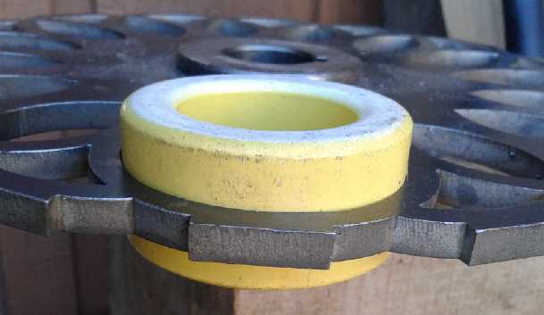
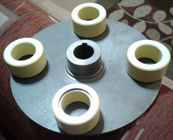 Then I looked
at a rotor with four cores sitting on it. A
big problem (all along) with using them was the there was nothing to
grip to hold them onto anything without having something extend past
the end. Well, really they were just iron powder with an epoxy coating.
What was the difference between that and sintered iron or cast iron?
Could I turn them on the lathe so they would have an inner mounting
surface that would leave the outside flush? How about a fat washer that
didn't stick out, with a flat head bolt? In spite of it being after 1
AM I took one out to the shop and turned it so it could be held in
place that way. It milled easily and it just took a minute.
Then I looked
at a rotor with four cores sitting on it. A
big problem (all along) with using them was the there was nothing to
grip to hold them onto anything without having something extend past
the end. Well, really they were just iron powder with an epoxy coating.
What was the difference between that and sintered iron or cast iron?
Could I turn them on the lathe so they would have an inner mounting
surface that would leave the outside flush? How about a fat washer that
didn't stick out, with a flat head bolt? In spite of it being after 1
AM I took one out to the shop and turned it so it could be held in
place that way. It milled easily and it just took a minute.
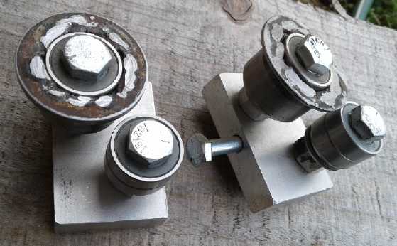
Great! That opened up new possibilities for using them.
Move to "Plan B": attach the "pucks" to this rotor
with four specially made "washers". Then make four pieces to
divide the edge into optical solids and gaps. Once the optical parts
were mounted and the flux gap was set by putting just the right
spacers on the shaft, it would be ready to run. That would seem to
be
the path of least reluctance. Too bad the coils were already made and
glued down - I could have done similar for the permanent magnet
"keepers". But first, I should get it to run as a simple reluctance
motor. The performance of that would be the benchmark.
 Then I got the "flower pattern" rotor off the shelf. If I
just made a few cuts and did some filing, I could put the four "pucks"
into holes in it, all perfectly aligned. Okay, "Plan C". On the 28th I
did one using a
jigsaw with a metal cutting blade. That seemed good. Then I realized it
needed
support in both directions - it could slide either
way. If I turned off say 1/32" from the outside but only went just over
half way across, and left a bit more material in the rotor holes, they
could slide in to there and no further. Then they'd only need to be
kept from sliding out the way they went in.
Then I got the "flower pattern" rotor off the shelf. If I
just made a few cuts and did some filing, I could put the four "pucks"
into holes in it, all perfectly aligned. Okay, "Plan C". On the 28th I
did one using a
jigsaw with a metal cutting blade. That seemed good. Then I realized it
needed
support in both directions - it could slide either
way. If I turned off say 1/32" from the outside but only went just over
half way across, and left a bit more material in the rotor holes, they
could slide in to there and no further. Then they'd only need to be
kept from sliding out the way they went in.
Even better would be to turn that 1/32" deep channel 1/4"
wide (the thickness of the rotor) in the center so they couldn't move
either way. But that would take some special and larger cuts in order
to insert the donut. (It would slide into a bigger hole closer to the
center of the rotor and then slide out to where it was held securely. A
piece would be bolted on to prevent the donut from sliding back toward
the center and the bigger hole. Hmm...)
Anyway, on the 29th and 30th I cut and filed out the other
three holes. The rotor would be the "back iron" of the toroidal rotor
poles and one edge of them would be flush with its surface - never mind
ideal balance for this one. Then I
would mill a 1/8" holding ring slot just below and make four 1/8" steel
pieces to (a) hold the poles in place and (b) form outside "optical
solids" for the optical interrupters. The shape of these pieces to do
this will be easier to figure out by cutting some pieces of cardboard.
These will be bolted to the rotor plate. (...Or is that really how I'll
do it?)
Other "Green" Electric Equipment Projects
Carmichael
Mill ("Bandsaw Alaska Mill")
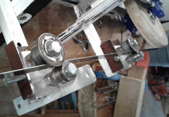
Front Pivot Self Adjusting Band Guides
After thinking
of this idea on June 30th, I made and
mounted them on the 4th and 5th. I wasn't quite sure how to do it. The
supports were behind the blade, not in front. Well... the saw was
somewhat symmetrical. I took the blade off, turned it inside out, and
put it on backwards facing the other way. Now the back was the front
and the motor was on the left instead of the right.
The "pickup truck canopy clamps" now seemed unsuitable. I
made two bars of aluminum .5" x 1.25" x 2.5", each with a 1/4" hole
going across the width in the middle as the pivot point. A 1/4" bolt
went through the sides of a piece of 1.25" wide "U" channel steel,
holding the pivoting bar in the middle. I mounted the wheels and
bearings such that the band crossed over the center line along the
bolt. I drilled bolt holes in the "U" channel pieces holding everything
to match the holes already in the mounting arms on the saw. So I got
the guide wheels mounted nicely. As I was turning the saw to adjust the
band tracking, my finger discovered a sharp shard of aluminum on the
pulley. It cut a fair slit and I quit for the day to nurse it.
I tried the saw out the next morning (6th). I was pretty
confident it would be great, but in fact it didn't behave well at all.
It started out about right, but angled up a bit to what should have
been above the cut depth and straightened out. Then it cut straight for
a
foot. I stopped to look and it seemed good. But after that it wouldn't
cut straight. It seemed that if the band started going up, the guides
indeed angled the band to cut downward, but the band twisted in the two
inches between the wheel and the wood and continued its upward climb.
Apparently it needed either more tension or a stiffer band. (and I
suppose that the wider the cut, the more tension is needed to keep
everything straight.)
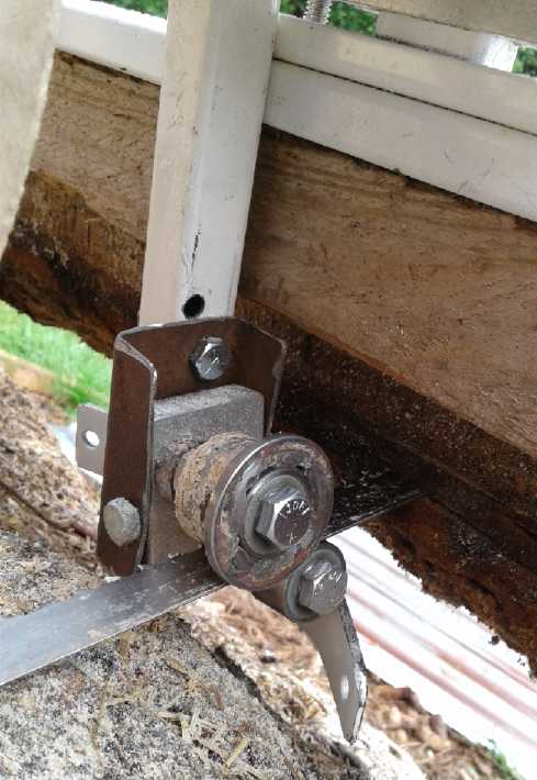
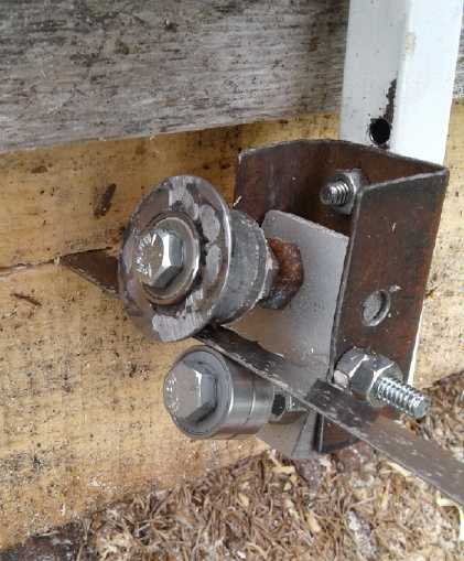 With the band and cut too high, the guides aim
the
With the band and cut too high, the guides aim
the
band down to bring the cut back to the intended line.
But the band twisted and kept cutting too high.
(The problem turned out to be an unsymmetrical band
with dull teeth and no set at all to the lower teeth.)
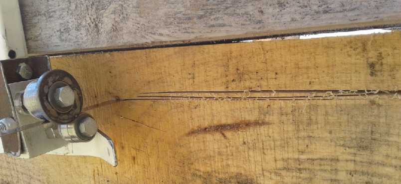 I increased tension on the band twice, and each
time it veered upward a little less than the previous time.
I increased tension on the band twice, and each
time it veered upward a little less than the previous time.
Then it did the one thing I really feared: it tracked
forward on all the wheels and started cutting into one of the steel "U"
channels holding the pivoting guide wheels, which of course would
immediately dull the teeth. I quit cutting.
That this was possible - perhaps even likely sooner or
later - was my biggest concern about the arrangement, but with all the
action going on one doesn't necessarily see it as it's happening. One
could hardly put a block of anything in front of the teeth to prevent
it from tracking/moving forward. It would either be cut up itself or
would dull the blade. But perhaps a wheel could be put in front
somewhere - plastic or aluminum. If the blade hit it, it wouldn't dull
the teeth. It would doubtless get gouged up some, but it would spin
with the blade and not be quickly sliced into very far. That would be
better than the blade hitting the working parts of the saw. And with
any luck it would make enough noise and vibration to alert the operator.
On the 12th (my guests having left) I looked around and
found a piece of 2" diameter UHMW plastic with a 5/16" hole in the
middle. A 5/16" bolt would suffice for an axle. (After all it was just
a safety... it wasn't supposed to spin.) Next, where and how to mount
it? I decided it should go just before the entry wheel, and could be
attached near or to its mounting.
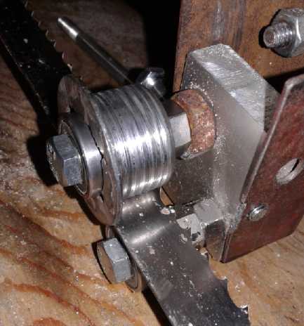
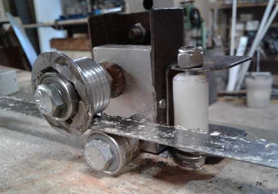 Left and right pivoting band guides with
wheels grooved to shed sawdust,
Left and right pivoting band guides with
wheels grooved to shed sawdust,
and a roller to protect the blade teeth if the band should track
forward.
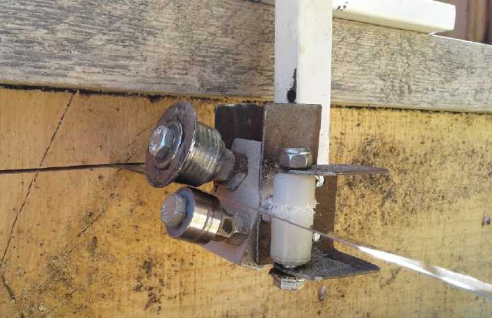 The band still veered up, and the protection
roller saw use at some point.
The band still veered up, and the protection
roller saw use at some point.
At the same time I had noted that the guide wheels had a
layer of sawdust caked onto them. In fact, it was glued on with spruce
pitch. There were patches glued onto the band in spots, too. Sticky
stuff, spruce pitch! Perhaps this was part of the problem. And in June
I had noticed that the guide wheels on the Woodmizer mill had
slots in the rolling surface - surely to help prevent sawdust from
sticking.
So - when I finally got to it - I did likewise, cutting in
some shallow grooves with the lathe on the 27th. I also cut a
piece of nylon rod about 3/4" diameter (nylon is harder than UHMW
polyethylene) and a piece of "U" channel steel for the front safety
roller. And on the lathe I drilled a hole through the rod for a 1/4"
axle. After
being waylayed by an underperfroming solar panel system and also hot
weather, I didn't finish until the next evening.
After a few details I took it out on the morning of the
29th. After starting well initially, it didn't cut well at all. Again I
could see that while the band guides were angled in the right direction
to correct the cuts, the band twisted between them and the wood, and
the cuts went bad anyway. I figured the tension must be too low and
adjusted it twice. If the band forms a bow inside the wood, the middle
twists the band in the wrong direction, compounding the error. The cuts
got closer with each adjustment, but still weren't entirely straight.
And when I continued to cut they got worse.
The band was getting pretty hot, and gradually it dawned
on me that hot metal expands, and that that would de-tension it. That
might explain why it seemed to cut well for the first foot or so, both
times, and then started going weird. So it
needed the water cooling not only to keep it from getting so hot the
teeth lost their temper, but also just to keep it from getting slack. I
kept going, very slowly and stopping to let things cool, and finished
the board. It was about the slowest cutting job ever. The board and the
piece remaining looked awful. (And I could see the first cut had
started going off - bowing - a little before it hit the sap pocket,
so the sap wasn't the initial problem.)
The next day, the 30th, I decided to try cutting another
board to see better what was happening. I cut just a few inches at a
time, then let the blade cool. It took much of the day, while I did
other things between each little cutting. There seemed to be three
unhelpful things happening. One was the band heating up. If I plucked
it when it was cold, it had a certain "twang". After cutting just a few
inches it was already hot, and the "twang' was almost an octave down -
not much more than half the tension. When it cooled, it regained the
higher pitch.
The second one was that the blade was
dull. The sawdust coming off was fine dust instead of tiny chips. Well,
that was no surprise since it had cut into steel
previously. (The nylon rod "stopper" seemed to prevent the band from
going too far forward at least once in the latest cuttings, as it now
has teeth marks in it.)
The third was that something seemed to be out of line. The
cuts - all of them - seemed to start out at the end of the cant with
the guide wheels level, a straight cut at the cut line. But from there
it would immediately start to cut upward, in spite of the guide wheels
pointing the band ever more downward as the cut rose. If I didn't let
the band get too hot it would cut through the piece without going
entirely crazy, but being all along above the intended cut line with
the guides aiming it down, more or less, depending on the band tension
and heat, and with the cut waving up and down. The twist in the band
would keep it from following the aim of the guide wheels, which were
always pointed strongly downward. And inside the wood the band arched
up between the two guides. The board would have a "cup" in it, greater
or lesser at various points depending (no doubt) on band tension, all
the way along, matched by the remaining piece underneath being domed.
Where I backed up and took another run at the same section, the new cut
would sometimes have less arch to it and the old cut could be seen in
the finished board.
But what was the cause of this? The guide wheels were
aligned with the main wheels. The pivot pins were directly in front of
and in line with the band. Could the blade be duller on one side than
the other? Perhaps the next thing to do would be to sharpen a blade,
since I had no more new ones. And (sigh!) order some more new ones.
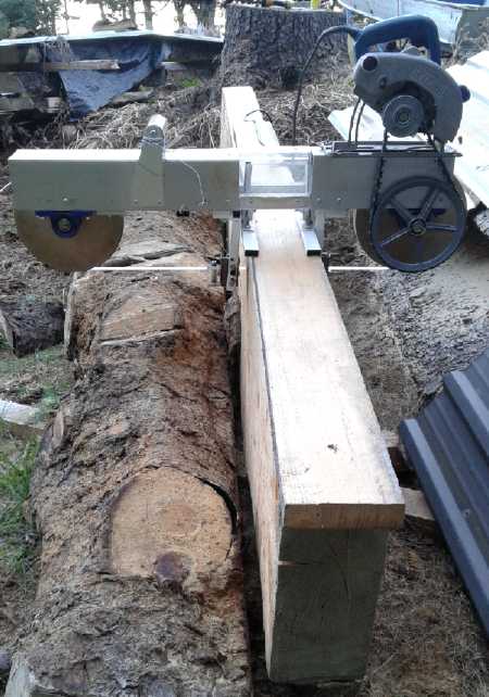 On the 31st I
took out my microscope lenses and looked at
the teeth on the band. It seemed the bottom teeth were duller than the
top ones. Then I noticed a more serious flaw: the bottom teeth were all
in-line with the band. Only the top teeth had any set to them. Well,
that would certainly cause it to veer upward! It must have hit
something that both bent them and dulled them at some point in the
trials. With any sort of 'regular' band guides, the cuts would have
just veered off and no board at all could have been cut. I examined out
the other two bands and they were both better. In fact, one was almost
like new. (Should I try and fix this one, or just change bands? hmm...)
On the 31st I
took out my microscope lenses and looked at
the teeth on the band. It seemed the bottom teeth were duller than the
top ones. Then I noticed a more serious flaw: the bottom teeth were all
in-line with the band. Only the top teeth had any set to them. Well,
that would certainly cause it to veer upward! It must have hit
something that both bent them and dulled them at some point in the
trials. With any sort of 'regular' band guides, the cuts would have
just veered off and no board at all could have been cut. I examined out
the other two bands and they were both better. In fact, one was almost
like new. (Should I try and fix this one, or just change bands? hmm...)
In the evening I sharpened the teeth as best I could with
a 5/16" round chainsaw file. (There was nothing quite the right shape,
and the file was too coarse. But the bands are hard to change and
adjust the tracking and I didn't want to take the time.)
Then I bent each lower tooth out a little with a small pair of pliers.
I also adjusted it narrower and used the 6" guide board instead of 8".
The blade didn't get hot as fast and ran more easily, with coarser
sawdust flying out. I stopped every foot or 15" or so for a couple of
minutes for cooling. The board wasn't perfectly straight and it still
had a little bow in many places, but it was much better and had been
much faster to cut.
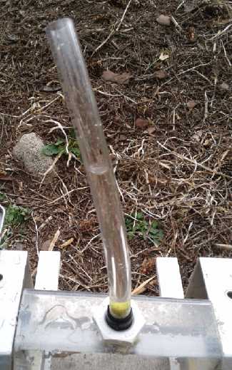 I (finally)
made a
little cooling water system with a sponge
touching the band at the top of its travel on August 2nd. To thread the
hole in the lexan to hold the plastic pipe fitting, I scored across the
threads of a similar copper pipe fitting with a zip disk in the angle
grinder, to turn it into a sharp "threading tap".
I (finally)
made a
little cooling water system with a sponge
touching the band at the top of its travel on August 2nd. To thread the
hole in the lexan to hold the plastic pipe fitting, I scored across the
threads of a similar copper pipe fitting with a zip disk in the angle
grinder, to turn it into a sharp "threading tap".
Then I tried
it out by cutting a couple of boards. Other than having to stop and
refill the thin tube 2 or 3 times while cutting (13' x 6" wide boards),
it worked well. The band never got more than warm. (Where did my fatter
transparent tube go? I have some somewhere.)
Again I didn't have to stop and adjust anything. But again
the cutting was slow and labored, the guide wheels were always above
the band aiming it down (not as badly as before) and the cuts had an
upward bow in them and weren't entirely straight along the board. But
at no point did the cut veer off and keep going until things jammed as
is so common for band mills especially with a dull blade.
I'm pretty
sure that with a good blade everything will be faster, smoother, freer
and the boards pretty flat and straight. By the end of the second board
the motor (Ryobi skillsaw) started to seem pretty warm. If the cutting
goes easier it probably won't get very hot even if used continuously.
Conclusions
The idea works. Self adjusting band guides are a huge
breakthrough for the design of
bandmills of any sort. They point the band the right direction to
correct the cuts, and with a half decent sharp blade/band having
sufficient band tension and stiffness, the cut can only follow their
aim. It should happen with so little movement up and down as to
be unnoticeable, and the boards should turn out quite flat. Even a
"somewhat dull" band, as long as it's symmetrical, should cut good
lumber - just more slowly.
It was probably slower than an Alaska mill with the dull,
off-kilter band and the cuts weren't very satisfactory, but no gasoline
was used, little sawdust was generated and some rough lumber was made.
If the band is sharp the
boards should turn out nicely straight with very little wood being
wasted to cut lumber even to very small dimensions. Obviously the next
test - now that it's set up better so it can't readily damage bands -
will be to do some cutting with a sharp one.
A big question is how wide of boards will it be practical
to cut with such a skinny, flexible band using so little power. If it
only does a good job up to 6 or 8 or 10" it will still be a valuable
tool for cutting big slabs and blocks into lumber with little waste. If
it does logs and slabs up to 18" or more, it might replace the chainsaw
type of mill, entirely or at least for smaller logs, and be priceless.
And of course one hopes it'll cut the thinner widths quickly and easily.
If the best band I have left cuts really well even to
quite wide cuts, I'll just order more the same. (And I'll want to find
a proper way to sharpen them and set the teeth.) Otherwise I might try
thicker bands, and maybe wider bands, to get reasonably perfect flat
cuts. Obviously with either more tension or with heavier bands more
width is possible. But then they'll need more power and pretty soon the
mill will be too heavy for one person to use handheld and for a 120 VAC
plug-in motor, since it's heavy enough as it is. (40 pounds) Some of
the components
might be lightened to allow heavier band components on the same
profile. (The 3/4" shafts and pillow-block bearings are needlessly
heavy. The 10" wheels could be lighter.) Well we'll see!
But if it's needed to cut larger logs, a mill on tracks
will also work better than any previous band mill. People who get one
will stop wishing they had a "real" dimensional or other mill, and they
won't be spending a lot of time adjusting instead of cutting.
Anyway it seems so promising now that I'm starting to
think I may get my spruce milled up into nice lumber before winter
after all! (First construction project with some of the spruce lumber:
a shed with racks to hold the rest of it out of the rain!)
Solar Panel
Installation
On the 14th, not only because they were going to waste and
the house-shading trees were now down, but
also with a view to clearing space in the shop to work on reluctance
motors, I decided it was finally time to put up the six large solar
panels stacked against almost the only open piece of wall in the shop.
(wall without
built-in shelves covering it). Four would go on the south facing roof.
I wasn't quite sure about the other two. One thing I do know is that
the prices keep getting cheaper, and even in this cloudy climate it's
probably worth getting some more. (In lieu of getting GeV HE ray
electromagnetic radiant energy working, of course.) Someone in a video
said solar panels in a "utility size" array can now make electricity
for 3 cents per kilowatt-hour (presumably US¢ = presently ~4¢
Canadian). And that nuclear is dead if only because the up-front costs
to build are staggering. (Not that they care about Chernobyl or
Fukishima.) And that wind power from ever
larger commercial windplants is now getting as cheap as solar, too.
I think 3 ¢/KWH is probably cheaper than coal. It's
certainly much cheaper than what most of us are paying! (A home
installation here saves about 13 ¢/KWH.) At any rate,
solar and wind are certainly far cheaper for the environment than
fossil fuel. The high summer temperatures and droughts we're seeing in
many parts of the world are actually being fortuitously moderated by
the fact that the last two solar cycles have been weaker than expected
with few sunspots and hence slightly less heat from the sun. The sun's
heat varies by about + or - 1%, and it must be at least at -1% now.
Since the Earth is around 300 °K, -1% might translate out to
average cooling of -3 °K or °C, -5 °F. Without coal and
petroleum burning there would be no global warming to speak of. People
are starting to die every summer in various locales from heat, even in
Canada, and everywhere seems to be on fire. If it doesn't end we'll all
gradually cook.
The 3¢ figure also reminds me of BC's Peace River "Site C"
hydro dam project. While I would rather see hydro in most any form than
coal and petroleum burning, I would rather see distributed floating
hydro, and I suspect that every year that goes by makes this dam hydro
project more uneconomic and a poorer reason to flood a huge river
valley environment. Anyway, the cost for me to install existing panels
and equipment is 'just' my labor. (This proved more costly than
expected.)
The next question was what to do with the electricity. I
had two 200 watt "Enphase" grid tie inverters and a Chinese ("Smart") 1
KW grid tie inverter. The 240 volt Enphase inverters, which I
bought earlier but have never used, have to be wired into an electrical
panel.The "Smart" just has a regular AC power cord to plug into any
electrical socket. But some long numbers say it meets somebody's
standards for grid-tie-in. Sending the power to the grid ensures
that whatever
power you make gets used somewhere and that it comes off your power
bill. And on this island in the summer if it's dry, there isn't enough
water for the one hydro plant. Then it's that much less diesel fuel
being burned. OTOH, it's supposed to be inspected and approved. That
seems like a lot of procedure to go to for a 1 KW peak plug-in unit.
Then, I had the idea for a 38 volt
DC power system with batteries. I could start making and trying out the
38 VDC plugs (and see if they might be improved in any way), and some
38 V LED lights (and ?? appliances). And a battery based power system
will only get more practical with cheap, high capacity batteries,
which, having invented them, I am presently hoping to have produced or
to produce.
Or, simplest, I could just run a 12 volt system similar to
the one I had in Victoria, using the same components. And hook up all
my NiMH batteries to it, since they're just going to waste right now.
I noted that in their last price list HES had a variety of
72
cell solar PV panels as well as 60 cell. (I at first had 60 & 72
confused with 54 & 60 and wondered why - 54 are no longer made
AFAIK.) The new 72 cell panels, which must be about 2 meters tall and
300 watts, are
rated as "36 volts". The open circuit voltage would be about 42-45
volts. Cruelly, trying to charge 36 volts with this would be like
trying to charge 18 volts with a 36 cell panel - as I found, it's just
not quite high enough voltage. OTOH to charge 24 Mn-Zn cells at 1.7
volts per cell would only take 40.8 volts instead of 42-42.6 for 30
Ni-MH or around 43.2 for 12 Li-ion. The difference might be just
enough. But I'd want to try charging 12 of them (18 V
nominal, 20.4 V to charge) with a 36 cell panel and see before I ran
out and got 72 cell
panels. (First I need to have good 12 Mn-Zn cells!) So if "36 volt"
panels aren't for charging 36 volt batteries, what are they for? I
think it comes down to the same reason I picked it as a good standard
line distribution voltage: it's the highest voltage that's safe to be
around when you might touch a live connection - as in, when installing
and wiring solar panels.
As for charging, I guess an MPP DC to DC converter at the
front of the voltage regulator that will be needed for an Mn-Zn battery
isn't an overwhelming extra circuit to add to the works.
Well, there's a pretty ambitious program, even without
reluctance motors and HE ray energy! At least I got the four large
solar PV panels up (~1 KW) on the 14th and 15th. I did a lot of
climbing up and down the ladder for things left on the roof or on the
ground that a bit more advance thought might have eliminated, but I
spend more time getting everything ready on the ground ...especially on
cleaning the glass. (Might as well have clean glass for a new
installation.) And a few of the lag bolts didn't go in properly. I got
5 longer ones later and fixed it up. (no high wind came, whew!)
The angle is better for summer than winter, but putting them up was a
breeze compared to on my old house in Esquimalt/Victoria with its very
high up, 45° angle roof. I poked my head into the attic to make
sure
none of the panel wires were shorted together. What to do with the
electricity was another project for another day.
Then I put the two remaining panels, the 208 watt, 54 cell
"oddballs", in the dungeon (er, root cellar). And I had the thought
that one of them plus a 100 watt 36 cell panel would both fit somewhere
as if they were a single 100 cm by 216 cm panel and make 90 cells for
45 volts (about 55 volts open circuit) to charge 36 to 40 volt
batteries for an "off grid" system without the aforementioned DC to DC
converter. But the cells on the smaller panel were
160 x 100 mm while on the large ones they were 160 x 160 mm, so one
wouldn't be able to get full current from the large panel, reducing the
pair to about 230 watts. Still, I could do two sets for 460 watts.
I got out the 1 KW grid tie inverter and looked at the
manual. It said it was a "microinverter" designed to be tied to a
single solar panel. Huh? The biggest panels are around 300 watts.
Surely one should be able to parallel 3 or 4 panels to feed this
inverter? Tying all four together was certainly what I had in mind. If
I was going to connect just one panel - or even two - I'd have bought
the 500 watt one.
I
started to think maybe the inverter wasn't really good for 1000 watts,
and also that it might not limit itself to what it could handle and
would fail if the panels had more than 1000 watts available. Just
because the brand name was "Smart" didn't necessarily make it so. But
it said it would shut off if it overheated until the temperature came
down. 95% of the time (around here) four panels would be well
under 1000 watts, but on those rare sunny summer days it just might max
out around
noon (1:48 PM PDT). I thought of connecting just three of the panels
to it, maximum about 760 watts. If the "1 KW" inverter had trouble with
that, I'd be pissed off.
A couple of days later I went up into the attic with the
same box wired with fuses and diodes that I had used in Victoria and
wired up all four panels. Then a nightmare began to unfold. I could
find no way to get the power wire from the attic to the large closet
that I wanted to use for a solar equipment room. (To skip
the gory details, skip the next 3 paragraphs.) I poked a wire through
the closet
ceiling but couldn't find it from the attic. Then I realized it was
under a different section of roof and I couldn't get there from the
attic. Then, the low rafters prevented outside wall access from the
attic along the whole length of the house on both sides.
On the 21st I located an interior wall that already had
some floor to ceiling wires running through it, for electric heat and
an outlet. From the crawl space the bottom of the wall could be
accessed; I could see and reach the back of the outlet box as well as
the wires. I drilled a hole from the attic into it. It would be
ideal. But how to push a wire through a wall with fiberglass insulation
[why?] in it? In wandering around looking for something I found an old
set of tent poles that assembled end to end with an elastic string
through them. Perfect! The attic there was just tall enough that I
could put the segments into the hole one by one and attach the next
one, until I'd pushed it right through to the bottom. It had a solid
"clunk" and I had obviously hit wood at the bottom. But I couldn't see
it from the crawl space. Where could it be? Maddening! Poking up with a
piece of coat hanger wire showed there was some cross piece of wood a
few inches above the inside floor level. That was what it had hit
against. Close but no banana. The cross piece was stopping my pole
inches above where I could access. Even if I could drill a hole in it,
finding that hole from the far end of a 9' pole sticking into another
hole was probably problematic. Definitely all the wires in there were
done before putting the gyproc on!
Then I went to the end wall (going the long way around but
at this point what the heck?) and tried to drill a hole through the top
plate of the wall. That's usually two 2"x4"s stacked on each other -
about 3.5" thick. At 9" I was still in solid wood. I thought perhaps I
had unhappily hit a wall stud an was drilling down through it, so I
tried again a few inches over. I gave up at 8" with the cordless drill
motor smelling hot.
Finally I drilled a hole through the plywood end wall into
a space above the garage ceiling and then sawed a hole in that ceiling.
Halejullah! - I could see my hole in the wall! But at this point I gave
up and decided to run the wire down the wall inside the garage instead
of inside the wall itself, and then poke it back through into the crawl
space. But I had to go out and that was that - a frustrating day and I
didn't get one wire run! So much for "a little before breakfast
job"! Was a kilowatt of solar power really worth all that cussing and
swearing? My 1879 house in Victoria was mostly simple to do wiring and
plumbing in compared to this 1987 one. You could poke wires up and down
through the chimney space and there was a lowered ceiling that made a
crawl space between the two floors in addition to the one under the
house and the tall attic space. A house 108 years newer didn't
translate to "planned for utility services access"!
The next afternoon and evening (22nd) I finished. The
closet end, under the low part of the floor, was a "crawl 30 feet on
your belly" [each way] job. I made it less painful by pushing pieces of
cardboard ahead of me to lie on. I drilled a hole above the cement and
went through two layers of wall with insulation between. I taped the
wire to the long drill bit and pushed it through the hole, even right
through, praying that if I couldn't find it in the house and had to
pull it back out, I wouldn't lose the drill. But the wire ended up in
the closet right about where I wanted it.
Then I went up into the attic again and redid the wires to
the four solar panels so that the wiring box was next to the outer wall
instead of far into the attic. I pulled a bit more wire through and
connected it. With the extra length of route, the #10 wire that I had
thought was so long was just about the right length and I didn't cut
it. Lacking cable staples, I tied it to other things in the crawlspace
with a few cable ties.
The next morning I started looking for solar equipment.
Where was that Zahn DC to DC converter? Not finding it in a short
search, I decided to try out the "Smart" grid tie inverter. It was
sunny with some haze. The inverter worked. It drew the panels down from
~35 volts to 25 or 26. It said never to connect the AC unless the DC
was connected. I wasn't impressed by the DC connection posts. They were
too close together risking shorting the panels, the threaded rods were
too short, and the plastic thumb nuts couldn't be tightened as much as
they should be (a) without pliers and (b) without fear of stripping the
short threads. It looked the "plus" wire had slipped, and when I
touched the unit there was a spark from the connection. I pulled out
the wall plug, turned it off, and improved the DC'+' connection. The
nut still wasn't very tight, but with small pliers I bent the stiff
wire around a bit farther, into more of a loop. I plugged it back in,
and somewhat to my surprise after several failed inverters, it still
worked. I left it there, on the entryway floor, getting very warm and
with its cooling fan periodically coming on and off. It certainly
seemed to be sending power to the grid.
I had a little 'power monitor' from Canadian Tire. You
plug that into the socket and then plug an appliance into it, and it
tells you how much electricity it's using including present watts and
amps and a running total KWH and cost (enter ¢/KWH). But it didn't
seem to tell how much was going from the appliance into the wallsocket.
That would be too simple! Maybe if I turned it around? But that would
mean two "cheater" cords to connect it - an F to F and and M to M. Ugh!
The power monitor was getting warm nonetheless while it read "zero", so
I turned off the inverter and unplugged the monitor.
Later it occurred to me the F-F could be just one of those
1 to 3 splitters that you plug into an outlet. I taped up the unused
male plug since it would be live. And I sacrificed a computer
power cord and put another male plug on the other end, and I hooked up
the power monitor backward. That seemed to work to measure the power.
But it said it was only making around 400 watts.
The low power level suggested that at least one and more
likely two panels weren't making a connection. It shows why it's a good
idea to measure these things. Sigh! Back to the attic and the
fiberglass dust. But not today!
I checked it out on the 27th. There didn't seem to be
anything wrong. The panels had bright sunshine. Each solar panel read
~29 volts. Both diode bridge outputs read 28.3 volts. (They were after
all tied together. All together the readings said the connections were
good.) Typical power monitor readings were 4.9 amps, 420 watts, 492
volt-amps and .85 power factor. The power company meter said I had used
12 KWH in a day in spite of whatever was generated. Could the power
monitor somehow be wrong, being used differently than intended? And was
the power company's meter not giving any credit for power generated
without a permit?
(And where was 12 KWH going in one day in July with no
heat on, no laundry, no bath? That would be 500 watts average. Surely
the fridge and freezer weren't that hungry. And a few LED lights at
night. And some computers and printers mostly on "sleep". And the
coffee maker but only for minutes. And the toaster, microwave and one
stove burner, but again for just minutes. And 70 watts of LED grow
lights on all day. And the well pump when I watered the garden. Hmm, I
guess it all adds up!)
I slit a 3-wire extension cord and checked the current
with two different clamp-on ampmeters. While the power monitor read 4.2
amps, both clamp-ons said it was 3.5 to 3.6 amps. Even lower! It worked
out pretty close if divided by the power factor. Well, I guess I'll
believe the monitor. How much power was the inverter spewing out as
heat, then?
Panel Connect Box in attic,
with heatsink. Black wires seen from one panel on roof
go to in-line fuse and then to a yellow cable (ex extension cord). The
four yellow
cables go to the square isolation diode bridges bolted to the sides of
the box with
connection wires soldered to them. (Only 2 diodes are used in each
bridge.) All the
"-" wires are tied together, and the two bridge output wires ("+") are
tied together,
and the "+" and "-" go to the white cable to the "equipment room"
closet.
Connections are all marrettes. (Primitive!)
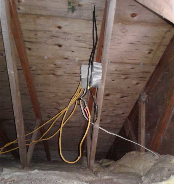 Then I tried the DC side. The DC clamp-on said just 17 or
18 amps, at about 25.5 volts. That's just 450 watts. (So the inverter
was apparently turning less than 50 watts into heat.) From four 250
watt panels in bright sunshine? I went back into the attic with the DC
clamp-on and measured the current from each panel. Sure enough, they
were only doing 3.6 or 4.5 amps each -- depending on which wire
and which way around the clamp-on was placed, which isn't very
confidence inspiring. (Was there some way to zero it? It must have .5
amps offset... Hmm, turning it on unconnected it reads about .2 amps.)
But it did say the panels just weren't putting out the promised 6 to 7
amps.
Then I tried the DC side. The DC clamp-on said just 17 or
18 amps, at about 25.5 volts. That's just 450 watts. (So the inverter
was apparently turning less than 50 watts into heat.) From four 250
watt panels in bright sunshine? I went back into the attic with the DC
clamp-on and measured the current from each panel. Sure enough, they
were only doing 3.6 or 4.5 amps each -- depending on which wire
and which way around the clamp-on was placed, which isn't very
confidence inspiring. (Was there some way to zero it? It must have .5
amps offset... Hmm, turning it on unconnected it reads about .2 amps.)
But it did say the panels just weren't putting out the promised 6 to 7
amps.
I went back into the attic (one more time) and verified
that the voltage was 28.3. It was 25.5 at the other end of the wire.
2.8 V * 17.5 A = 50 watts was being lost in that long #10 wire. I knew
I wanted to keep it short!
I also discovered to my dismay that the diode/junction box
was pretty hot. .7 V * 17.5 A = 12 watts being turned into heat by the
diodes. (Another place for synchronous rectification?) It needed a
heatsink. I wasn't looking for yet another job! But it was hot, and
screwed to a rafter. I dug out a heatsink and in the search found the
Zahn DC to DC converter (18 to 40 volts converts to 14 volts, output
adjustable within a range.) After putting a couple of holes in it I
took the heatsink up to the attic (yet again), dimounted the box and
remounted it on the heatsink. Since I didn't know the hole spacings in
the box, I just made one #8 threaded hole in the heatsink. With just
one bolt (and no heatsink compound), the box stayed a lot warmer than
the heatsink. But it was cooler than it had been, and now the heatsink
was between it and the wood.
A while later with the sun directly in line with the
house, it was doing 432 watts steady. And almost 100 watts was being
lost, half of it in the long #10 cable.
Cheap Grid Tie Inverter: cheated!
For a while I couldn't figure out why it was hardly
over half of the rated amount from each panel. (I cleaned the glass!
It's not fair!) Then t started to dawn on me... MPP for the panels was
supposed to be (IIRC) 27.4 volts. I measured the panel voltage (all
four panels) at the box as 29 volts. So really, it doesn't seem to be
drawing them down far enough. That would be the "Smart" grid tie
inverter's fault. In fact... as I think about it... it puts out around
420 watts for most of the day, seemingly almost regardless of the sun
angle. Later in the day the voltage at the inverter was down to 24.5
volts but it was still doing 420 watts. I suspect it's really a 500
watt inverter with a "1000 Watts" label on it so they can charge more
money. Why else do they say to hook it to a single panel? If you do,
you'll never find out it only puts out under 420 watts regardless of
what's available from the panels. I began to realize the product wasn't
as advertised. Power and current don't match the specs given in the
manual. There are no controls on the inverter or clues in the manual as
to how to change anything. I didn't know that "Smart" meant "dishonest"
and "unethical". That smarts! I can't remember how much I paid for it,
only that it looked like a good deal. Perhaps it was "too good to be
true." At 420 watts instead of double
that, the utility meter only slows down instead of reversing. It's
really only using two of the four panels most of the day.
Oh well, at
least it works. Nothing has blown up. I bought it too long ago to
complain now. If I was "into" it I'd buy another one (a different one
from somewhere else) and get all the panels mounted and hooked up. And
I might connect those two "Enphase" 200 watt grid tie inverters to the
two 54 cell, 208 watt panels. Then I'd be making well over 1000 watts
to the grid... on our uncommon sunny days. And according to the utility
meter, that would still be less then I'm using daily. 8 panels instead
of 4, and of course fully and properly tied to the grid, should make it
a surplus - on sunny summer days.
And speaking of cheap stuff, I put another power monitor
in the line. This one, "#2", read about 20-30 watts less than the first
one. I put "#1" on my coffee maker and it read 950 watts where the
second one had said 900. It didn't seem I had much of anything that was
very confidence inspiring! The plate on the coffee maker said "900
Watts". So the "#2" monitor was probably more accurate, and the
inverter was actually putting a little under 400 watts to the
grid, and turning more power into heat; probably around 50 watts. Let's
see... 16.5 A * 25.5 V = 420.75 watts in from the panels, and the power
monitor says 380 watts out. That's 41 watts of heat. So diodes (12) +
wire (50) + inverter (41) = 103 watts being lost to make 380 watts out
- just over 20% losses. This is why I like to keep the number of
components in the circuit to a minimum, and to charge batteries
straight from the panels if possible. (And I certainly tried to find a
shorter route for the cable!)
380 watts seemed like a lot less than 420. I put power
monitor #1 back on and it still only said 390. What was different from
yesterday? I had changed a "computer" power cord - one from a box to
the one that
came with the inverter. I put the old one back on, and it went up to
405 watts! (Still not 420.) I got the fattest computer cord I could
find, and 2' shorter, but it didn't seem to make any difference. What
about the M to M "cheater cord"? It was the thinnest. I cut it from 5'
to only 9" long. It didn't seem to make any difference either. An hour
later, with the sun rising toward its zenith, the monitor said around
415 watts. Was the inverter putting out more toward midday, or
was it the power monitor unit warming up and reading higher? I put
#2 back on and it read about 390. Some of each?
Well, enough of that! As it is, the system should make
more power when I get it
"off grid" and I'm not using this inverter - if I harness that power
effectively.
Thinking about off-grid storage, and about the Suzuki
Swift fire that had almost burned the house down, I started thinking
that it would be safer to be charging storage batteries away from the
house. Theoretically there should never be a problem, but then there's
equipment failures that might potentially deliver the full power of the
panels to the batteries and cause them to overheat. So having spent all
that aggravating time running the wire, I decided the battery
installation should go elsewhere, outside - and the other direction was
where the outbuilding clutter was. (Hmm... or maybe I could put them in
a
metal or gyproc box of some sort in the other garage on the cement
floor,
not far from the "wiring closet" and out of the weather.)
I started looking at the power meter and noticed that even
with the solar savings the house was using about 12 KWH/day - most of
it when
the sun wasn't shining on the panels. (The panels, with the
half-size inverter, were only saving around 3 KWH, instead of 6.) On
about the 4th day, the 30th, it said the previous day had used 18 KWH.
Why? I couldn't recall doing anything extra that would use all that.
But after not driving anywhere for a few days, I finally remembered I
had
driven to Tlell and back the previous day, almost 50 Km. (It just
seemed too hot to work, so I went visiting.) Recharging the car
accounted quite nicely for the extra. (That dollar's worth(?) of
electricity would have been around 7.50$ for gasoline around here.)
August 1st was the first cloudy day since putting up the
panels. I put the slit extension cord on and with the inverter running
measured 1.6 amps going to the line. At the measured 122 volts, that
was just under 200 watts. The next day was even duller. From 2.2 amps
(270 W) earlier in the day the readings dropped to 1.25 A (all @ 122 V)
for 150 W (and then a light, misty rain started). Obviously that was
all the four panels were supplying. (probably not much more than
the average of what the freezer plus the fridge were using.) So it was
only on sunny days the low powered inverter was wasting capacity. Nice
as July was, sunny days are a minority around here, so the loss over a
year wouldn't be that great.
But apparently if one wanted to try to offset one's own
summer electricity use in this climate (never mind winter), 10 panels
or more and inverters to
match would be pretty minimal. If I hooked up my other two panels to
make six, all the power would be in use the majority of the time.
Should I get another grid tie inverter and make a real, official
installation? Better to hook up the Zahn DC to DC converter and get my
neglected batteries charged.
Synchronous Rectification?
Losing 12 watts in the solar panel isolation diodes and in
the process making the box in the attic hot makes me think of
"synchronous rectification" whereby a power MOSFET is turned ON when
the diode is to conduct, and OFF when it isn't. The voltage drop
through an ON mosfet, perhaps .1 volts, is very low compared to .7
volts in a diode, and
so almost no power is lost to heat. The problem is when to turn the
mosfet on or off. When it's ON, the voltage is virtually the same on
both sides. One would have to either periodically turn OFF the line
and see if the panel voltage goes up or down compared to the load side,
or else sense whether current is coming from or going into the panel
with a relatively sensitive monitoring system. Or perhaps even the very
slight drop across the mosfet could be used to turn a comparator on or
off?
A synchronous rectifier "panel isolation" system would
virtually eliminate the diode losses. Not that that's the big loss in
this system, but it probably wouldn't cost much more than diodes, which
need to be installed anyway, and every bit helps. In fact, if it
eliminates a heatsink, which does cost some money, it should be cheaper.
Rechargeable
Battery Making
with oxalate electrolyte:
* Nickel-Zinc *
* Manganese-Zinc *
* Lead-Zinc *
Electrolyte Additives Note
I would note that although the primary component of the
electrolyte is potassium oxalate, a small amount of sodium oxalate (or
even some other oxalate) might improve some characteristic or other.
This is worth experimentation. The chief constraint is that other than
potassium, most oxalates aren't very soluble, so not much can be added.
Retesting the lead-zinc cells
On the 10th my visitors left, and my [presumably more pure]
calcium
hydroxide arrived. After sitting a couple of weeks or more, one
lead-zinc cell read about .8 volts, the other about .25. Both the lead
and the zinc plates seemed to be well stuck to the separator paper. So
it
wasn't possible to remove them for inspection without wrecking the
separators. I did a first battery experiment: squeezing out the old
electrolyte and diluting it in water, and putting in new in the .8 volt
lead-zinc cell with the three zinc sheet plates. But first I used one
of the nitrate-nitrite test strips in the old electrolyte. There didn't
seem to be any. Was there some mystery contaminant in the pottery
supply calcium oxide that caused discharge, or was I wrong [again,
still] and
the cause lay elsewhere?
The lead-zinc cell I had been testing had started doing
funny things before I had quit testing it last time, and I found the
"+" terminal lead (wire) had fallen off the lead (Pb). I soldered it
back on again.
The voltage seemed to drop pretty quickly. I charged it
longer, 3 or 4 hours. That helped. Then I remembered the other cause of
self discharge, oxygen getting in. I covered over the top as best I
could with modeling clay. Charge current wasn't high and the short
circuit current was under 1/2 an amp. Perhaps the concentration of
electrolyte was too low?
It didn't look like I had got far on elimination of
remnant self discharge. was still down to 1.700 volts in about 20
minutes, and losing almost 2 mV/minute. Now, even assuming it had
anything like a seal, how much oxygen was in the air space under the
lid? Could left over oxygen, and poor sealing, be the real culprit? Or
worse, if the zinc bubbled hydrogen and made pressure while charging
(once it was mostly or fully charged), might it suck more air in later,
each time or continually? Or if the lead was fully charged, it would
bubble oxygen inside the cell, leaving it there to gradually discharge
the zinc electrode. Commercial manganese-zinc dry cells with their very
low self
discharge were, after all, well sealed. (And also they didn't get
recharged.) Perhaps what I mostly needed was a proper case, and perhaps
care not to overcharge?
I had just dumped some K2C2O4 and CaO into the empty cell,
put the electrodes back in, and then added some water. I pried open
part of the top and dumped in some more K2C2O4. Charge current didn't
seem to go up, but when I shorted it it went up to .7 amps. But wasn't
this the same cell that put out 7 amps short circuit current when I
first made it? Why now just 1/10th of the current? Instead of 1.3 volts
into a 1 ohm load, it just managed .38. A little later I took it off
charge and shorted it again. The current started at over .8 amps and
instead of dropping clawed its way up to a full amp over 10 seconds or
so. With a one ohm load it started near .28 volts and again rose in
several seconds to .382. Perhaps it was just short of oxalate, and what
I had added was taking time to mix with the pure water that I'd soaked
the workings in to try to eliminate the old electrolyte. It continued
to improve.
By the 12th the cell was acting funny again. The voltage
readings were jumping all over. I pulled pretty hard on the "+" wire
and the voltage reading rose and became steady while I held it. The
obvious culprit was the soldered connection, which was underneath the
modeling clay cover. It's amazing how fast things go bad inside a
battery if it's not right. No figures were given in the solubility
table for tin oxide or oxalate, but basically tin with a positive
charge was going to dissolve or at least disintegrate in most anything
and leave the wire with a high resistance connection to the cell.
...and could its reactions have anything to do with the gradual self
discharge? (Can you solder with lead and no tin? Where did my flux pen
go so I could try that? I wanted it last time but couldn't find it. I
finally did, much later.)
At that point I was tired of the Pb-Zn cells and working
on a new cell.
Lead-Acid Battery Capacity Note
In the last issue I estimated that the small 'motorcycle'
battery I bought was about 4 amp hours or less. It weighed 1.67 Kg. Now
I've found another old lead battery of similar size, 1.52 Kg, which
says on it "4.0 amp-hours". So the estimate was probably pretty close.
Battery Type Energy Storage Comparisons
Again I can't help remark on the contrast: an alkaline
"D" cell is 12-18 amp-hours and I weighed a couple at 143 grams each.
Both types, Pb-Pb and Mn-Zn, yield their maximum amp-hours at low
discharge rates so we compare the 4 with the 18. It takes 8 Mn-Zn cells
for 12 volts, so 1.14 Kg for over four times as much energy - from a
cheaper chemistry that can now be made highly rechargeable.
Furthermore, compared to a Ni-MH "D" cell, with 1.5 volts
instead of 1.2, and with 18 amp-hours instead of 10, it's
1.5/1.2*18/10=2.25 times as much energy storage. And by weight, 163 g
(Ni-MH) / 143 g (Mn-Zn) makes it 2.56 times the energy by weight. Since
Ni-MH more typically puts out 1.25 volts and Mn-Zn may be somewhat
under 1.5, the comparison may be somewhat overstated, but we may fairly
say a Mn-Zn "D" cell has twice the energy storage capacity of a Ni-MH
"D" cell and
well over twice by weight. And very low self discharge.
NEXT CELL: A New Larger Cell in a New Case
On the 11th I decided to make a Mn-Zn cell with bigger
electrodes, 4" x 3". (=100 mm * 75 mm = 75 sq.cm faces... One manganese
dioxide electrode with a zinc electrode on each face should give a few
amps.) I would cut flat pieces of ABS plastic and 'glue' them together
with methylene chloride for a custom size case.
Manganese Dioxide Pocket Electrode(s)
I put the 'from scratch' Mn-Zn electrodes from last month
into water to dissolve out any electrolyte contamination. After a day
there seemed to be a bluish color in the liquid. I wasn't sure if it
was dissolved or precipitate. It didn't look uniformly distributed. I
decanted some water off the top and it looked clear. Best guess was
copper oxide powder. Maybe the copper mesh wasn't going to last
forever, even if the electrode itself would? (Then again, the electrode
had been disturbed more than once and was falling apart in general.)
I wanted to try out cupro-nickel for the new current
collector for a MnO2 electrode instead of just copper. But I only had
sheet, not mesh. And it was heavy and stiff. (Why did I get such a
thick sheet?) I couldn't see how the powder could be induced to stick
to that, so I decided to make a "pocket" electrode with the
MnO2/graphite powder held inside a thin "pocket" of perforated sheet
metal. I took a piece of the old #28 gauge nickel-brass from 2008. That
at least seemed more suitable in thickness. I tried punching holes in
it with the pin frog in the press, but I stopped at 3-1/2 tons and
there were no holes, only slight indentations. The trouble with etching
holes into it is that I don't have a silkscreen or PCB print ready to
do it with, and it seemes like a fair project to make something decent
along those lines.
Pocket Electrodes: Perforating Sheet Metal with a "Bed of Nails"
Somewhat frustrated I took a roofing nail and a hammer and
punched a few holes. That at least seemed to work, and somehow it
suggested the
idea to drill a whole bunch of holes in a row in a piece of wood to
slip roofing nails through. They could be pounded into the sheet metal
one at a time without needing a huge force. I didn't put the holes far
enough apart and the heads overlapped. I found some other small nails
still with flat heads that wouldn't go through the holes, and made four
rows of twelve holes for these nails more closely spaced. I used the
milling machine and cranked the handle 4 turns per nail to get the
holes
evenly spaced. (A CNC drilling setup would have been ideal for this.
And next time maybe I'd make enough rows to do the entire electrode.) I
set it on the piece of sheet with a softwood 2"x4" under it and
hammered on the nails until they had all gone in a bit. The metal was
perforated at every nail. I then did my best to put another set of
holes in the spaces between the first set. It was hard to tell about
the alignment and they weren't even (and if you turn it over to look
closer the nails fall out), but it did seem workable and I did both
faces. To my surprise the nails had little tendency to want to
stick in the holes they made in the metal and the metal pulled away
easily. I bent some of the sides
partly up to make the "pocket" into which the powder could be placed
and compacted by squeezing it between the faces. Then the bending could
be completed with a hammer or pliers.
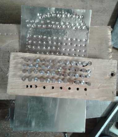
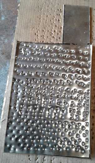 First try at a perforated nickel-brass pocket
electrode.
First try at a perforated nickel-brass pocket
electrode.
Then I started thinking about electrode size if I made
more. If I was using sheets 6" x 12" as all the nickel-brass sheets
were, the optimum use of the metal would probably be to make 5" x 2.5"
electrode pockets from a single piece of metal. They would be cut to 3"
x 12", and a 1.75" square would be cut out of one end, leaving a 1.75"
long x 1.25" wide connection tab sticking up. After punching the holes,
the edges would be bent up 1/4" to form closed edges that would be
crimped over so the powder
couldn't fall out. The bottom 1/4" and then the bottom 5.25" would then
be folded up, closing off
the top, bottom and sides, with the MnO2 & graphite powder
contained. (It might
need something to hold the middle areas from bulging. Rivets across? or
just push everything into the cell and
let separator pads press against the pocket?) A key feature is that it
would all be one single
piece of sheet metal for the most solid possible connection throughout
and hence highest current capacity. The rolls of zinc metal being 3"
wide as well (oops, 2-5/8"), zinc pocket electrodes could be done
pretty much the same
way.
Since the nails didn't tend to "stick"
to the metal, I thought I'd do a new "bed of nails" block with fine,
short finishing nails - perhaps 5/8" in a 1/2" plastic block since they
don't need to stick out very far. With the small heads they could be
very closely spaced. I would do them in an "X" pattern with alternating
rows at 45° angles for closest spacing. I might just make it big
enough to do an entire electrode in one stamping without moving it
around - several hundred nails. Or 2.5" x 2.5". If it's not a mass
production tool, and if it doesn't make the ideal pattern of very fine,
very closely spaced holes, it's at least an adequate, simple and
replicable way of perforating metal sheets.
Almost since I started trying to make batteries ten years
ago I've wanted to make pocket electrodes, but I kept running up on the
rock of not finding any satisfactory way to perforate a piece of sheet
metal - or even graphite or plastic. After all the unusual and
unsatisfactory things I've tried... Here it Is!
On the 15th I tried making a better "bed of nails" block
with 3/4" finishing nails. I measured one nail as 1.13 mm diameter, and
I used a 1/16" (1.58 mm) drill bit. Instead of turning the crank 4
turns I went 1.5 turns. I drilled 5 rows of 31 holes and broke 3 drill
bits. It was just as well I stopped there because it wasn't very good
and it didn't work very well. For all I was using a 'precision' milling
machine the holes weren't even at the top, and the drill wandered and
they came out in wild positions at the bottom. Trying to use it, it was
too even a pressure over too small an area. It felt like I was pounding
on a solid instead of nail points, and the sheet metal formed a dish
under the nails instead of just being punctured where each nail was.
I took out the finishing nails and put in cigar box nails
in every second hole in the first, third and fifth rows. That seemed to
work adequately. I know the commercially made ones have far more
tinier, closely spaced holes. Doubtless that's optimum, but I expect
there's a lot of room for variation without losing a lot of current
capacity.
Pick a Size
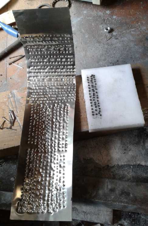 I cut a 3" x
12" piece of nickel-brass for a shell and I
went over the whole electrode perforating a patch at a time. Then I
bent it up to make the outer shell and cut off the part that wasn't the
tab at the top. (101 elephant jokes... Q:How do you carve an elephant?
A: Get a big block of marble and chisel away everything that doesn't
look like an elephant.) BTW you leave the jagged edges of the holes
inside. It's more current collector surface for more of the powder to
contact to.
I cut a 3" x
12" piece of nickel-brass for a shell and I
went over the whole electrode perforating a patch at a time. Then I
bent it up to make the outer shell and cut off the part that wasn't the
tab at the top. (101 elephant jokes... Q:How do you carve an elephant?
A: Get a big block of marble and chisel away everything that doesn't
look like an elephant.) BTW you leave the jagged edges of the holes
inside. It's more current collector surface for more of the powder to
contact to.
I weighed the piece: 60.1 grams. That of course is dead loss as far as
adding amp-hours is concerned. But if it was much thinner it wouldn't
be very strong. So the more powder I can stuff in there, the less the
negative impact of the weight of the sheet metal. (After all, you don't
want negative impact in a positive electrode!)
Dimensions excluding the terminal tab were 2.625" x 5.0" x
.3" or 67 x 128 x 7 mm. Hopefully the electrode inside will be 125 x 64
x 6 mm. That's 160 sq.cm counting both sides. At 25 mA/sq.cm that would
be 4 amps. It might put out 10 if shorted. Or it might (hopefully) do
substantially better. Making it would tell.
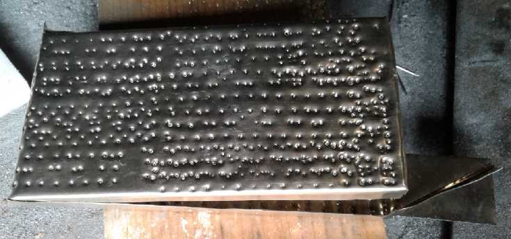 Folding it up after perforating
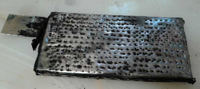 Loaded with 25+ amp-hours of MnO2
For the other side, would simple zinc metal plates
suffice, or should they be double layers or zinc powder filled pockets?
Before going to too much trouble with zinc electrodes, I decided to
fill the MnO2 pocket and see how much electrode substance it had. After
packing in some MnO2 paste (which now included some Veegum and a small
squirt of Sunlight
dishsoap) and then compacting it and squashing out liquid at 5 tons
pressure (over the whole electrode) it weighed 180 grams, so 120 g of
paste. I dented the sides of the electrode with a hammer and
screwdriver while it was in the press. It seemed to stay shut, but it
really needs something more positive to hold it. Perhaps if I hit the
edges with a nail or an awl that would 'rivet' the two edge pieces
together.
I took apart a couple of "F" cells. The "+" powder weighed
about 80-90 grams and one rather corroded zinc can was 15, the other
17. It probably started out well over 20 grams, but it still shows how
little zinc metal it takes to match a positive electrode oxide
powder... at least if it's in chloride that gets dissolved away as it
discharges. 25 grams of zinc is 20.5 amp-hours if it's fully utilized.
So it might be a guess that the cells are actually under 20 AH.
Taking 85 as the median, the electrode had 120/85=1.41 "F"
cells worth of MnO2 mix. If we take an "F" cell to be 20 amp-hours,
that would be 28 amp-hours. (And let's not forget the potential of
another 14 amp-hours at 1.2 volts instead of 1.5 volts for 42
amp-hours... and another potential 14 at about 1 volt, but that's
getting pretty far down... and assuming sufficient zinc.) So with two
such Mn electrodes in the cell,
that would be 56 amp-hours with another 28 in reserve at lower voltage.
More zinc electrode ideas
To match 56 amp-hours requires 68 grams of zinc, or
matching the 84 amp-hours that's available down to 1.2 volts, it would
be just over 100 grams -- if the zinc was 100% utilized. But if it's
only 10% utilized, that's 680 grams or 1 Kg - more than all the rest of
the battery.
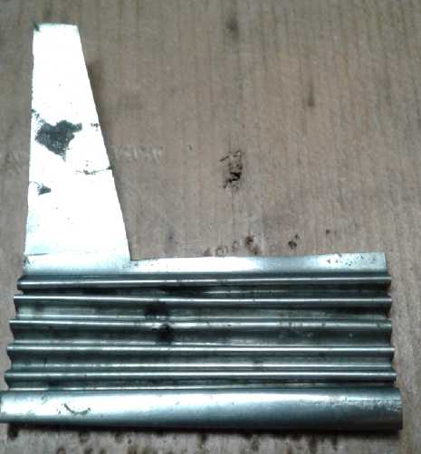 Last month I
thought of folding up zinc sheets to give
them more surface area. This month it occurs to me to also put zinc
powder into the folds. The powder (if not too fine) should add further
zinc surface area while taking nothing away from the mechanical
properties or electrolyte penetration of the metal sheets.
Last month I
thought of folding up zinc sheets to give
them more surface area. This month it occurs to me to also put zinc
powder into the folds. The powder (if not too fine) should add further
zinc surface area while taking nothing away from the mechanical
properties or electrolyte penetration of the metal sheets.
I also wonder how much surface area could be added to the
sheets by some deep gouging or perhaps coarse sanding? That might be an
alternative to texturing in the rolling mill. It should even be better
- if sufficient surface convolutedness can be attained.
I tried folding the zinc sheet by primitive methods rather
than in a sheet metal break. It was thin and soft enough to fold over
any sharp corner, so I started thinking of how some good folds such as
those in the cross section drawings of last month might be accomplished
by hand for a prototype.
I put a spare 2.5" square zinc
electrode in a vise with two thin pieces of hard metal. I bent it
around 180° each time and then reversed it and moved it up for the
next fold. It ended up 2.5" x 1", less than 1/2 its original face size.
But it was pretty irregular. And I would rather somewhat stretch out
the zinc for the extra surface rather than simply fold it. (Thinner
plus more surface area.)
I started thinking also of making aluminum rollers - for
the rolling mill or to drive with a motor - with the requisite surfaces
on them to reliably and uniformly create the fan-folds, or with slots
to hold harder metal to bite into the zinc. (Or could I find two
splined shafts, or wide gears with fine teeth, that meshed "just
right"?)
But I started to think this was mostly ways to get the
same
zinc sheet into a smaller area. Except for stretching it a bit to get
somewhat more surface per volume, it didn't address the low utilization
of the sheets. Surely powder should do that? And surely the best way to
do that would be to make pocket electrodes - same as the "plus" side
only considerably thinner. The volume of zinc powder to make up the
required grams of zinc wouldn't be much.
The zinc metal for the pocket was just half the weight (32
g) of the nickel-brass one (60 g), and it would contribute to the
amp-hours.
That would determine how much zinc (getting hopefully, say, 20% of
theoretical capacity) would be needed to match the amp-hours.
And I found I had a jar of somewhat coarser zinc powder to
try out for pocket electrodes.
Ugh! I had thought the zinc strips were 3" wide, but on
the 15th I measured the roll as 2-11/16" wide. The new roll was
2-9/16". So much for all the metal being a neat 3" width! Time to
recalculate potential sizes. Better finding out now than after making
more "odd size" electrodes that won't match. But plain zinc sheets
should match the width of the folded cupro-nickel pockets quite nicely.
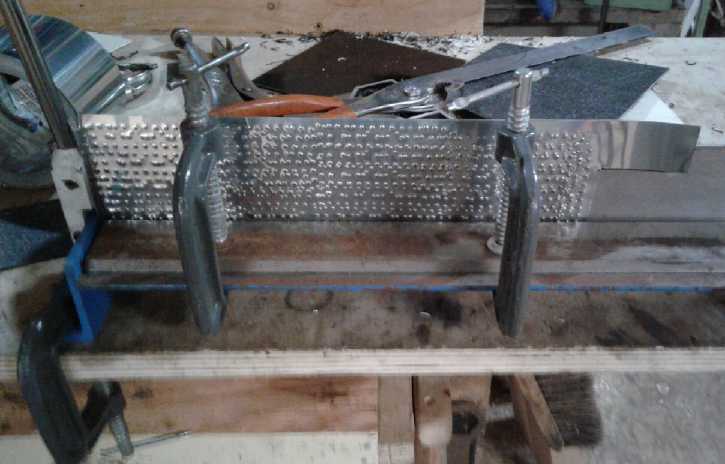 Bending up the edges of the zinc electrode
Separators?
Making pocket electrodes and zinc sheet (or pocket)
electrodes gives
the idea that with solid pieces of metal facing each other in a flooded
cell, simple plastic spacer pieces to keep the separator sheets from
touching are often used rather than paper or fabric sheets. It's simple
and inert. And in experiments, electrodes in a cell can be swapped
around without being "stuck" to a separator paper.
ABS Plastic Case
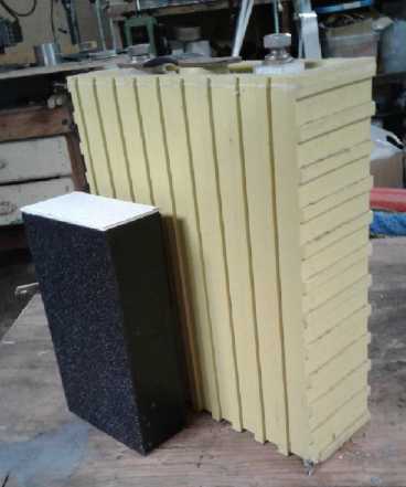 On the 16th I
cut out a case. Inside it was 2.75" wide,
5.25" tall, and 36 mm thick. I used 1/16" ABS for the outer faces, and
1/4" ABS for the top, bottom and sides, so it had to be 3.25" wide,
5.75" tall and about 40 mm thick. The top had an extra piece of 1/16"
of the outer dimensions to keep the fat piece from falling in. It was
black except I made one edge white to be the "+" side, and the top face
white as well. It was all "glued" together with methylene chloride.
(surface dissolves in a bit of methylene chloride squirted on at the
joins through a very fine "syringe" tube, and then re-hardens as the
methylene chloride evaporates.) It weighed 138 grams.
On the 16th I
cut out a case. Inside it was 2.75" wide,
5.25" tall, and 36 mm thick. I used 1/16" ABS for the outer faces, and
1/4" ABS for the top, bottom and sides, so it had to be 3.25" wide,
5.75" tall and about 40 mm thick. The top had an extra piece of 1/16"
of the outer dimensions to keep the fat piece from falling in. It was
black except I made one edge white to be the "+" side, and the top face
white as well. It was all "glued" together with methylene chloride.
(surface dissolves in a bit of methylene chloride squirted on at the
joins through a very fine "syringe" tube, and then re-hardens as the
methylene chloride evaporates.) It weighed 138 grams.
I filled it with water and it leaked part way up one side.
Fixed with a little more M.C. I was glad I thought to try that first.
Unfortunately it wasn't the only leak.
How did it look next to a 3.4 Kg, 3.2 volt, 100 AH
lithium? 2/3 as thick, 1/2 as wide, 2/3 as tall. Maybe 1/5 the
overall size. But it would take 2 to get the voltage and 1-1/2 to get
100 amp-hours (actually 84 AH - at rated voltage). That's 3, total 3/5
the size and
maybe 2/3 the weight. But then if you really needed the range (and
assuming sufficient zinc), you would still
be able to drive maybe 35% farther at lower power as the Mn2O3
converted to Mn3O4. That would of course all assume these were ideal
capacity cells and that you could draw 100+ amps from them as you can
from the lithiums. Hah! Fat chance of that. But if my
first cells don't meet expectations, that's still the potential.
Cell assembly and Tests
The cell: Case, zinc pocket electrode, MnO2
pocket electrode, electrode separator, lid
(slots for electrode connection tabs were cut into lid later)
I designed the cell to hold 2 "+" electrodes and 3 "-"
with 1/16" separators between. But for the first tests I just wanted
one of each. What was the current capacity for one pair of faces? Would
the amp-hours double (along with the amps) when a second zinc electrode
was added? On the 18th I filled in much of the the empty space with
pieces of plastic. I used the zinc pocket electrode with no powder in
it, just the zinc sheet. Having added no calcium oxide yet, I wet a
brush and painted it on the outside of the MnO2 electrode. If it was
going to suffuse into the electrode, it would have to do so through the
perforations. Then I mixed up 500 cc of water with 180 grams of
potassium oxalate. It didn't all seem to dissolve (not quickly, anyway)
so I added another 100 cc of water. Each time after it settled, there
was still a K2C2O4 layer caked on the bottom. Admittedly the water was
from the fridge, so the 36 grams per 100 cc maximum figure may not have
applied until it warmed up. A hydrometer test showed 1.15 g/cc.
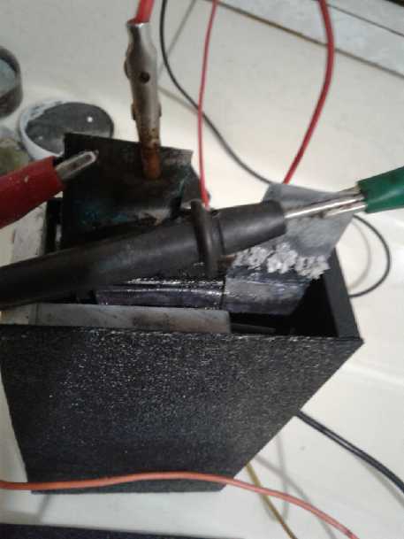 I got the cell
filled with electrolyte (~100 cc) and
connected in the evening (18th). It initially read .699 volts and only
put out .22 amps when shorted. Of course the zinc started as 'charged'
metal, so the old MnO2 mix from the dry cells with the corroded zinc
must have been pretty much discharged to Mn(OH)2. To charge that the
zinc electrode would then have been bubbling H2. I didn't see any
bubbles, but the level had gone down to where it was harder to see -
and it looked like in spite of my precautions, the cell leaked.
I got the cell
filled with electrolyte (~100 cc) and
connected in the evening (18th). It initially read .699 volts and only
put out .22 amps when shorted. Of course the zinc started as 'charged'
metal, so the old MnO2 mix from the dry cells with the corroded zinc
must have been pretty much discharged to Mn(OH)2. To charge that the
zinc electrode would then have been bubbling H2. I didn't see any
bubbles, but the level had gone down to where it was harder to see -
and it looked like in spite of my precautions, the cell leaked.
With the power supply giving a 1.7 volt charge it initially drew 140
mA, which dropped to 80 by 1/2 an hour. This didn't seem like much
current going into such a big battery. And it would only put out an amp
for a moment when shorted, which quickly dropped to 3/4 amp. This
seemed pretty disappointing from such a big cell. There were a number
of possibilities. First, the separator plastic was 1/16" ABS. A piece
of paper would get them closer together, and that seems to make a
difference. Second, there were far fewer holes, spaced much farther
apart, than in commercial pocket electrodes. That might well be
limiting the rate at which the electrolyte could carry ions back and
forth. I decided the second "+" electrode would have to have at least
double the density of holes and see if that helped. The maximum instant
short circuit current rose with charging, even to two amps, but
whatever it was it dropped off to well under an amp in a second or two.
I put a 2 ohm load on it and it delivered .25 amps for
about 6 minutes. Then I found a couple of 1.5 ohm resistors (arg, WHERE
have all my low ohms, 5 watt resistors gone? There's a big bag of them
somewhere.) and changed to 3 ohms. It put out over .21 amps (.63 volts)
for a further 10 minutes. After that I stopped it. In a few minutes it
had recovered to 1.2 volts and then I resumed charging, which started
at .21 amps but dropped to .12 in a few minutes and .07 a while later.
Soon I put all four resistors in series for 5 ohms. It
started at about 1 volt, but dropped fairly rapidly to .82 volts - 165
mA, and carried on a much slower descent from there. After 7 minutes it
was down to .75 volts/150 mA and by ten minutes, .72/144 mA. It
recovered to 1.23 volts and then I put on the 11 ohm load without a
recharge. It started at 1 volt or so and after a couple of minutes was
down to .9 V/82 mA; 5 minutes .876 V; 10 minutes .862; 15 m, .851 V; 20
m, .840 V/76 mA.
These tests seemed to show the cell has some good storage
capacity, but is unable to receive or deliver it at desirable rates of
speed. Even at low rates it delivers with serious voltage drops. I'm
thinking an insufficient number of holes in the sheet metal are
drastically limiting the effective interface area over what it should
be.
I charged it overnight, but by morning too much
electrolyte had leaked out and I disconnected everything. In the
evening I fixed the leak (I hoped) and put it back together with fresh
electrolyte. It started out at .84 volts, so it hadn't kept much
charge. This time it started charging at 1/3 of an amp but it dropped
to 80 mA pretty quickly. At the risk of potentially generating some
permanganate I raised the charge voltage to 1.8 and current went up to
120 mA. Then I thought that maybe generating some permanganate for a
limited period might actually be helpful: dissolved MnO4- could reform
into MnO2 in contact with the electrode, but only in contact with it,
so connection could be improved. Perhaps even better would be if I put
some KMnO4 into the electrode mix when I made it. Something to try in
the next electrode. For this one I raised the charge voltage to 2 volts
for a while. It started charging at 200 mA. At least that was getting a
little current into it!
But it gradually became apparent that it still leaked! The
case business seemed to be trickier than it appeared. Cutting the edge
pieces had to be precision width and the ends absolutely square. I
decided it was time to work on something else for a while. The first
time I managed to get my thumbnail in at a seamor two . Naturally I
figured that was where the leak(s) was, and I 'glued' liberally. On the
23rd there was nothing so obvious - it was much tighter everywhere. But
I had a look with the 10x microscope lens. There were great gaping
chasms everywhere around the edges, and plastic with bubbles in it. It
looked awful. Leaks could be anywhere. But there was probably only one,
somewhere.
I put a small piece of ABS in a jar and dripped in some
M.C. That softened it, so I could smear it into anything that looked
like any sort of gap. I did have to put it in the jar again and after
just a smear or two, and soon find another little piece, but soon I
couldn't see how it could possibly leak. But I had become more
suspicious and tried filling it with water and setting it on a dry
paper towel. Any wetness should become evident, and it was soon
there... a corner that looked fine was dripping. Again, that was
probably from the bottom piece being just a hair wider than
the edge
piece, leaving a hair gap. And then aother one from the opposite
corner. Hmm, wrong corner, or was it both corners on this side? Then I
filled it to the brim. Another leak, 2/3 of the way up one seam! This
one could only be blamed on rough cutting, or virtually no pressure to
push the faces together. I refilled it and left it a while... and there
was still a damp spot. Water was seeping out of a corner I had
already "fixed". After that it seemed to hold.
This case had more leaks than the US government! What a
headache! I must get the sides absolutely precision, all pieces
identical width and with absolutely square ends, and very smooth cuts.
Then the sequence... First glue the bottom to one face, then the edges
to that face and the bottom, all square and lined up. Put a heavy
weight on it to hold it and leave it a while. Then glue the other face
on and press it again. Hopefully such improved procedure should solve
the problems. Otherwise I might have to get into plastic welding - ugh.
23rd: The cell finally held water and I put the battery
back together, sans lid, and on charge.
24th: I could see occasional bubbles of hydrogen coming
off the zinc as the MnO2 charged. But if the cell really had 25 AH of
MnO2, and if it would only charge at 160 mA, it would take a week to go
from "empty" to "full". And since the charge current at 1.8 volts would
gradually drop off as it charged, it could be considerably longer. That
might explain the slow changes over a day of charging. After about
two days, the voltage started staying higher longer and the short
circuit current started going up. There were momentary currents over 4
amps, but they quickly dropped off to 1/2 an amp.
I tried sticking in an extra piece of plastic to squeeze
the electrodes, and in particular to better press the MnO2 mix powder
against the perforated metal, but that made it worse instead of better.
More holes, more holes! I suspect twice as many would double the
continual current and the charge rate, and four times would quadruple
it, etc. Even more would be needed before the law of diminishing
returns set in. The thing to do would be to make the second "+"
electrode and put way more holes in it.
I'll get back to it. I think it's a great size cell to
produce multiples of. But for the moment I moved on to other things. Is
there an easy and better way to do the perforations?
Also I saw a friend with a table saw and we cut some new
edge pieces from my 1/4" ABS. They were smoother than my cuts, and the
pieces were all precisely the same width as close as I could tell. I
have some hopes for the next case to be watertight on the first
try.
Better, Faster Perforating: Ideas for Rollers with "Nails"
Even after at last having something that more or less
worked, I kept thinking about how to perforate sheets of metal better -
to make more holes better and faster. Making such big plates for large
cells, perforating each one was pretty tedious, and the more the hole
density, the more laborious. I kept coming back to the rollers idea;
one roller with short "nails" sticking out and the other with matching
holes for them to punch into. But everything would have to perfectly
align, with the rollers geared together.
Finally I had a bit of an idea. Instead of holes, the
other roller could have "slits" going around for the nails to pass
into. Then they only had to line up side to side - much simpler. One
roller could be driven and the other would simply follow it, and if it
slipped a bit it wouldn't matter.
Another thought would be to have the piece slide across a
single roller of nails with a piece of soft wood sliding across it. The
nails would then simply go through into the wood.
For a second idea, I could use the milling machine and the
rotary table to mount the roller to be perforated, in order to line up
the holes to insert the "nails" into, both axially and radially. (I'm
assuming a tiny drill bit can be coaxed to go in straight and not break
if I get it right! There's probably some way to ensure the drill depth
is consistent, too.)
For a third idea, the roller could do 1/4 density. The
piece could be fed through twice with the holes punching in different
places. Then too, the holes could set be slightly off center so that if
the 3.0" wide piece was turned around, the rows of holes would align in
between the first rows.
At first I keep thinking too that the easiest thing for me
would be to make the rollers to fit my jeweler's rolling mill. At the
cost of making custom rollers that wouldn't fit anything else, that
would give them a solid mounting, a thickness/spacing adjustment and a
crank handle.
OTOH rollers could simply be made from 1" or larger
shafts, and then they'd fit on 1" needle bearings or bronze bushings.
Then one could either attach a crank handle or a much speed reduced
motor. They'd need solid steel sides to hold the bearings and keep the
rollers at the right distance apart.
I wonder if the nails could go into an aluminum cylinder
instead of steel. That should be a heck of a lot easier to drill the
array of holes into than hard axle steel. I might even say "possible"
versus "it'll never work!" I found an aluminum cylinder in my scraps,
about 1.5" O.D. and (?)24 mm I.D., and 4" long. That might be just
about ideal, other than having to turn a 1" axle down to the I.D. to
fit it. Or maybe I could use a boring bar and increase the I.D. to one
inch?
Lead-Zinc Cell From Scratch With Rolled-up Sheet Metal Electrodes
On the 24th my 1' x 2' x 1/32" sheet of lead arrived in
the mail. It was heavy, 4 # @ 2 #/sq.ft. The material was 15 $US and
the shipping (IIRC) was 25. I'd have got more for a volume discount,
but the shipping just went up rapidly.
Someone on a list had mentioned the idea of just rolling
up two strips of metal. It was for off-grid storage and they didn't
care about weight and bulk. In 1865 Gaston Planté did just that
to invent the lead-acid battery. He rolled up two strips of lead with
separators and filled the container with sulfuric acid. The lead-zinc
cell should be able to be done the same way, of course with one zinc
strip and the oxalate/lime electrolyte. And of course this is what I
ordered the lead strip, just to try it out. I decided to cut 2 foot
strips of lead and zinc, about 2-5/8" tall (the width of thinner roll
of zinc).
Perhaps the cleverest thing I did was to start cutting at
1" instead of at the end, and then to cut a tab on the far end. Thus
the first two rolled electrodes (if there would be another one) would
each be one piece with a terminal tab that was part of the lead sheet,
without wasting any of the sheet. No corroding tin solder in this one!
Then I rolled it in the jewellers rolling mill both to stretch it and
to put a pattern in the surface, both to give it more surface area for
its volume. It ended up expanding from 23" to 30.75". The thickness
went down from .9 mm to .6 -.7 mm. So the dimensions were about 69 mm x
781 mm x .6 mm, and it weighed 435 grams. (Wow, almost 1/2 a kilogram.
Of course everything depends on what percentage of theoretical it will
actually use. It won't be 100 amp hours, but if it uses 10% it might be
around 10 amp hours.) The interface area, counting both sides of both
sheets, is 1078 sq.cm. Even at just 10 mA/sq.cm that should be 11 amps,
and it's more likely to be 50 amps momentary. (If it gets over 20 I'll
have to use a clamp-on ampmeter rather than a DVOM!)
I put the zinc in the mill without cutting it off the roll
and textured/stretched it. Then I cut it at 31". I couldn't do the tab
the same way since there was no more width to cut from, but I cut the
end 3/4 of the way and then folded the tab piece up. It seemed to be
shorter than the lead, so I ran it through the rolling mill a couple
more times, which helped a bit but seemed more just to put kinks in it.
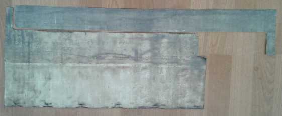 The remaining original sheet of lead (Pb) with
the
The remaining original sheet of lead (Pb) with
the
piece I cut off and stretched in the rolling mill
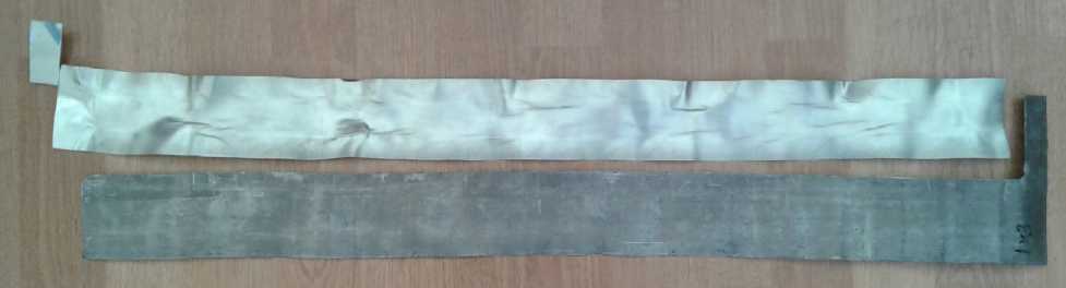 The two stretched sheets, zinc and lead, to be
rolled up together
The two stretched sheets, zinc and lead, to be
rolled up together
with separators between as a 'rolled electrodes' Pb-Zn cell.
These will go in a soup can or a plastic pipe section.
Easy as it should have been to finish it, I turned to
other neglected projects for the rest of July.
http://www.TurquoiseEnergy.com
Haida Gwaii, BC Canada