Turquoise Energy Ltd. News #124
covering
September
2018 (Posted October 4th)
Lawnhill BC Canada
by Craig Carmichael
www.TurquoiseEnergy.com
= www.ElectricCaik.com
= www.ElectricHubcap.com
= www.ElectricWeel.com
Highlight: "Improved 2 KW" ultra-efficient Piggott
Generator built and works great!
(See
Month in Brief, Electricity Generation)
Month
In Brief
(Project Summaries etc.)
- Milling - Nails - Water Pump - Ordered 305 W solar panels -
Piggott Generator - Sprint 36 V car charging - Swiilawiid
Sustainability Society Symposium - Energy Co-op for Tidal Power?
In
Passing
(Miscellaneous topics, editorial comments & opinionated rants)
- Red Quinoa
- HOW Much Money?!? - Monsanto Sellouts: Justice Served?
- Project Reports
-
Electric
Transport - Electric Hubcap Motor Systems
* Solar Battery Charging for the Electric Chevy Sprint and Miles Cargo
Van - a better plan
Other "Green"
Electric Equipment Projects
* Carmichael Mill ("Handheld Bandsaw Alaska Mill") - Milling
Alder - Spruce: Nails - Automatic Band Sharpener - 1295 $?
Electricity Generation
*
Improved Piggott Axial Flux PM (permanent magnet) Generator - magnet
rotors - coil winding - case - assembly - testing - What to use it for?
- VAWT, Tidal Experiments - Saving Mixed Epoxy for Later - commercial
prospects: 1295 $.
* A very small hydro project using Sprint car alternator I converted to
PM generator in 2016
* Tidal Power Project: 100 KW Floating Tidal Power Vessel - Smaller
Propellers in Venturis? - Self Steering to Optimum Position in Stream,
collision avoidance, "return to shore" for maintenance
Electricity Storage -
Turquoise Battery
Project (Now Mn-Zn, Ni-Zn or Pb-Zn)
* Manganese-Zinc Cell
 On the 3rd and
4th I finished cutting up the alder log I had felled - three sections 8
to 10 feet long. I cut it down to compare milling something else -
almost anything else - with the spruce, which has interwoven grain and
seemed like really tough stuff to mill. Having not tried anything else
though, I wasn't really sure. Sure enough, the alder cut like a dream
compared to the spruce and I cut the tree into lumber in about 3
sessions.
On the 3rd and
4th I finished cutting up the alder log I had felled - three sections 8
to 10 feet long. I cut it down to compare milling something else -
almost anything else - with the spruce, which has interwoven grain and
seemed like really tough stuff to mill. Having not tried anything else
though, I wasn't really sure. Sure enough, the alder cut like a dream
compared to the spruce and I cut the tree into lumber in about 3
sessions.
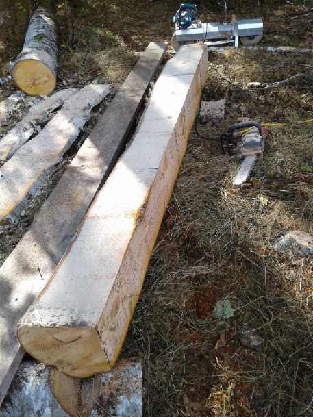
The last and widest section I cut into beveled siding with
a "live" (bark) bottom edge. I thought this would look interesting.
 On the 6th I
went back to the spruce and the saw found nails embedded in one of the
pieces. These dulled my last two bands and cutting was over for the
month. Trees near houses are prone to having nails. People will nail a
fence or something to it or up a put a clothesline, then later the tree
grows over the forgotten nails.
On the 6th I
went back to the spruce and the saw found nails embedded in one of the
pieces. These dulled my last two bands and cutting was over for the
month. Trees near houses are prone to having nails. People will nail a
fence or something to it or up a put a clothesline, then later the tree
grows over the forgotten nails.
 A supermagnet found yet a third nail buried
just under
A supermagnet found yet a third nail buried
just under
the surface still farther up the length. By this time I
had cut about 2 feet off the end.
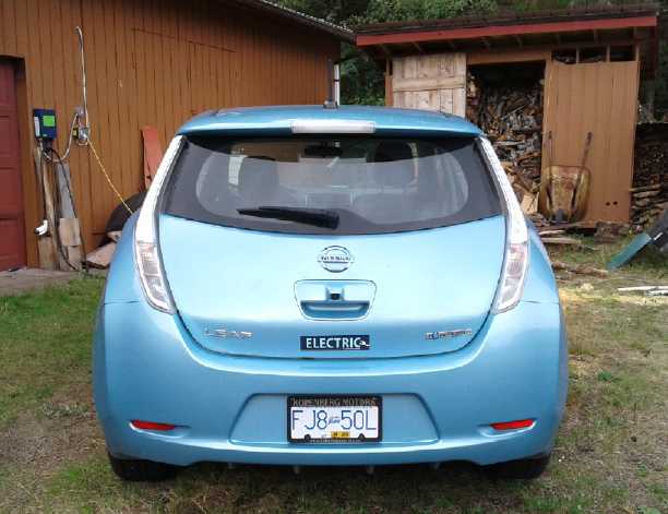 I
had been noticing people liked
my Nissan Leaf - especially the color - but didn't even realize it was
electric. "Electric Blue for the electric car!" I tell them. I think
the car companies still only sell electric cars reluctantly and don't
want to enlighten other drivers that perhaps they don't need to be
burning gasoline. Tom sent me up an "Electric" sticker from Victoria
and I stuck it on the tailgate.
I
had been noticing people liked
my Nissan Leaf - especially the color - but didn't even realize it was
electric. "Electric Blue for the electric car!" I tell them. I think
the car companies still only sell electric cars reluctantly and don't
want to enlighten other drivers that perhaps they don't need to be
burning gasoline. Tom sent me up an "Electric" sticker from Victoria
and I stuck it on the tailgate.
Trouble at the Pass - water pump clogged up
On the evening of the 8th my water pump clogged up. Black
sludge and soon nothing at all came out of the taps. I shut off the
power to the water heater. Luckily my neighbor, one of the family of
previous owners of the house, knew a lot about wells and pumps and had
in fact set this one up. He explained that one needed a four foot
section of 3/4 inch threaded steel pipe. This was inserted down to
where the water line/pipe went through a special fitting to pass
through the body of the 6" well pipe about 2 feet under the ground, and
screwed into the special fitting there. (That's below the freezing
level. Otherwise the top of the well would have to be in a heated
enclosure to prevent a pipe coming out the top from freezing.) Wiggle
it and lift, and the fitting slides apart and the plastic pipe lifts
up. Then the entire pump with its 2" plastic hose, power wires and rope
is pulled out of the ground -- in this case 60 or 70 feet of black PE
plastic pipe. I had to drive to Masset at the far end of the island to
buy a piece of 3/4" pipe as neither of us seemed to have one. I found a
short piece and a coupling to 1/2" pipe, which I did have a short piece
of, to make a long enough piece.
Well, there's more than you - or I - ever wanted to know
about deep wells and pumps - and a round about way of saying I didn't
get to too much project work on the 9th and 10th. We chopped off 4 feet
of the plastic pipe so the pump would hopefully hang well above the
sludge, and put it back. That was still way below the water level
inside the well. It was well there two of us to pull the plastic pipe
out of the well pipe, and to do it without kinking it. It pumped, and
after a while the black-as-oil water started clearing. Maybe I'll have
better water now, without periodic bouts of black water from the taps?
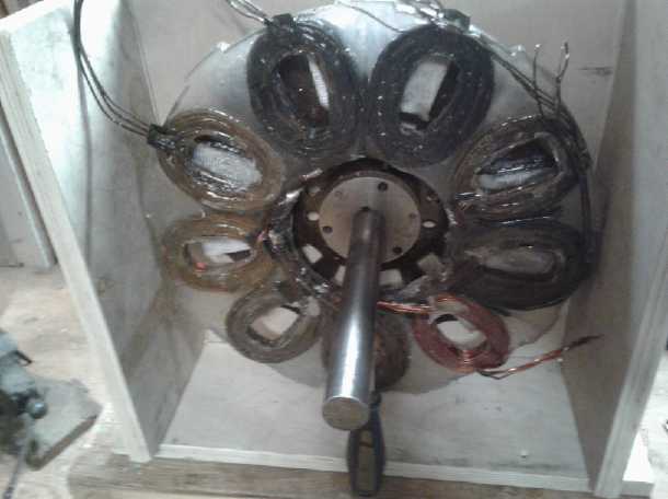
Improved Piggott Generator
So after the 6th and 7th it must have been from the 11th
or so that I got back to work on the "Improved Axial Flux Piggott
Alternator". I finished the rotors and then wound the stator coils.
Then I screwed the coils by their winding centers to the stator mold,
wired them, and filled the mold with epoxy.
 A finished rotor, magnet side down. (2nd coat
of epoxy setting)
A finished rotor, magnet side down. (2nd coat
of epoxy setting)
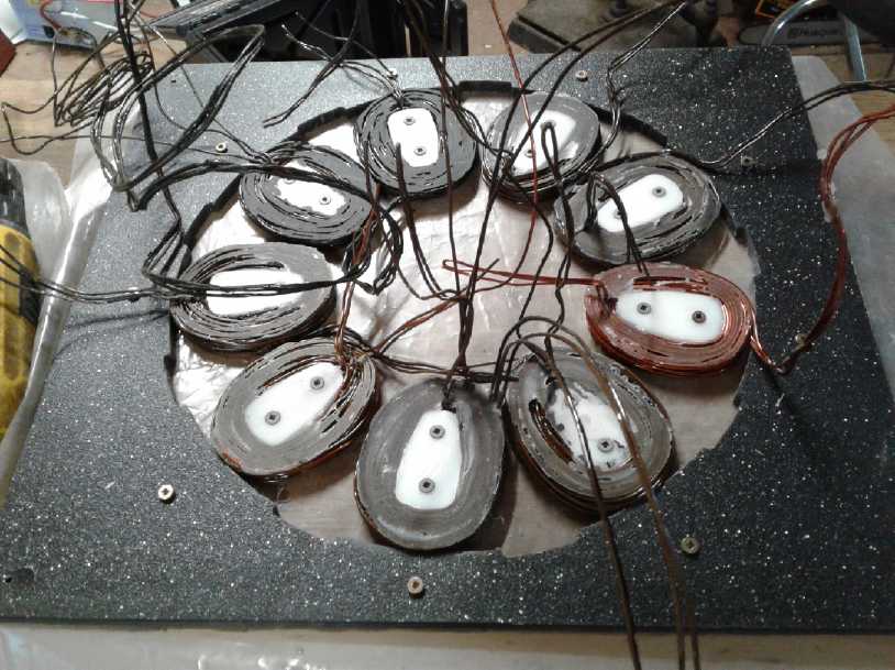
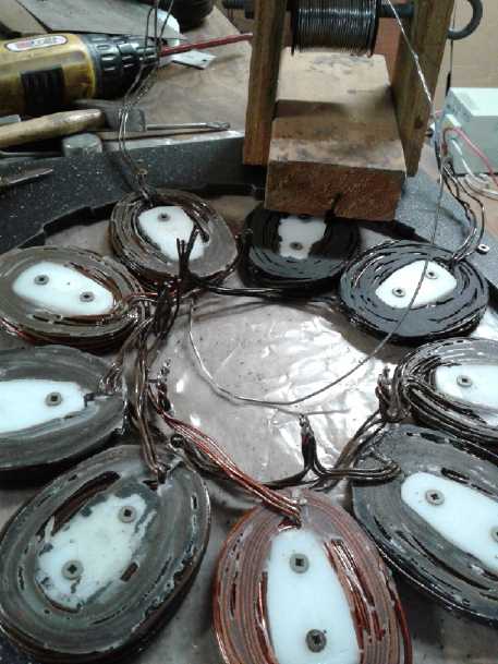 Wiring the Stator
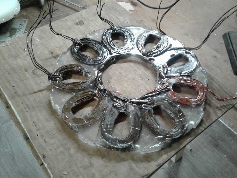 Finished molded epoxy stator
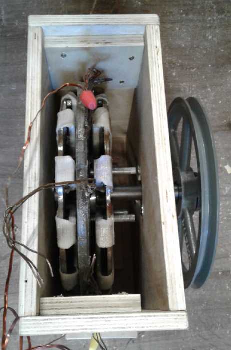
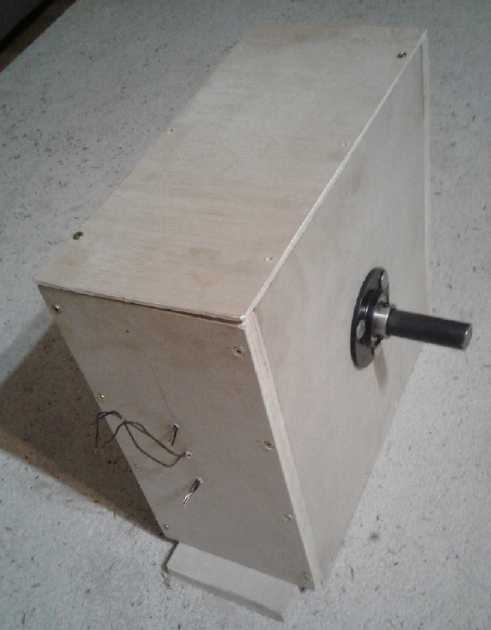
Generator in wooden chassis. The outer rotors
with magnets spin past
the stator, a cast ring of epoxied copper coils, which remains
stationary.
The magnetism from supermagnets on both sides provides very large
electro-
magnetic interaction even with no iron in the stator coils and at very
low RPMs.
On the 20th I made a case from birch plywood. I finished
the unit in September before the symposium except for a few finishing
touches like air flow holes in the case and flamproof paint on the
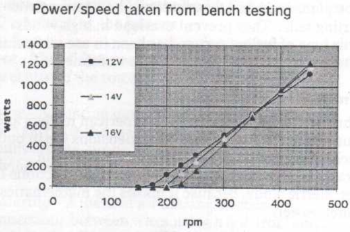
plywood. I tested it by running it with a pulley from my 2 HP radial
arm saw motor, and got some very good results - voltages to charge
batteries and 62 amps short circuit current between two phases at 270
RPM. It looks like when I get some high current diodes to convert it
from 3-phase to DC, it should meet the top lines in Piggott's
performance graph from his book How to Build a Windplant, and
extend them out to 2 KW (maximum power point - MPP) at 600 RPM:
I'm glad I took a bit of
time to do the testing. It gave me much more confidence in speaking
about the unit.
A Crate of Solar Panels
HES Home Energy sent out a new price list, and then a new
sales rep at the Victoria office sent an intro e-mail. I looked at the
price list. The best deal seemed to be Hanwha 305 watt(!!!) 60 cell
panels for only a little more than 265 watt panels. (And there were 345
watt, 72 cell panels for not so much more than that! They just keep on
getting better!) I got the idea to order a palette of them to sell at
the Swiilawiid Energy Symposium on the 29th and 30th and I e-mailed
him. (Pronounced "sweeluweed". Not as bad as "quinoa" - "keenwah", I
suppose.)
I thought there might be 20 panels on a palette, but it
turned out there were 32 in a crate, for what would be about 8500$ by
the time I got them. But an extra 5% discount for a whole crate on top
of 30% for wholesale, and being crated and stored in Vancouver I could
ship them (insured) on the North Arm barge for arrival in late October,
which I'm pretty sure is substantially cheaper than by truck. On the
20th I bit the bullet and ordered them. Nobody seemed interested at the
symposium. There was a lady there who does approved solar panel
installations who also buys from HES. (Very knowledgeable.) Hopefully I
can sell them with ads on line (HaidaGwaiiTrader.com) to pay for the
five or so I've decided to keep. I'd better!
36 Volt Chevy Sprint EV Charging
On the 21st I took the Sprint out for a spin around the
acreage for the first time in a while and as I suspected the batteries
were down a bit. I still hadn't installed a proper charging system. The
lead-acid battery chargers should raise the voltage
up to 14.4 volts - a little much for lithiums - before they would
decide a battery was charged and shut off. I had decided to put a diode
in series with each of the three chargers (12+12+12=36 volt car) so the
battery voltage would actually be .7 volts less than the charger
thought it was.
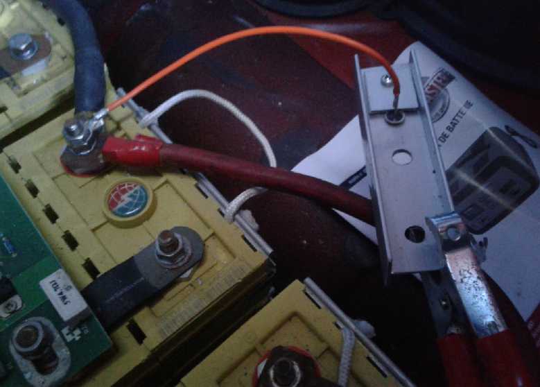 But the diodes
would dissipate up to 7 watts and needed heatsinks. I looked on the
shelf and there was a length of aluminum "H" bar. I cut three pieces 5"
long, found 3 car alternator diodes, and assembled them with a #14 wire
to connect to the battery. The charger connected to the aluminum bar. I
put them in the car and put it on charge. Each "10 amp" charger put out
6 to 8 amps. The heatsinks got quite warm but not hot. The "8" was the
one at the front under the hood, that powered the car 12 volt circuits
as well as the drive motor. Presumbly it was a little more discharged.
But the diodes
would dissipate up to 7 watts and needed heatsinks. I looked on the
shelf and there was a length of aluminum "H" bar. I cut three pieces 5"
long, found 3 car alternator diodes, and assembled them with a #14 wire
to connect to the battery. The charger connected to the aluminum bar. I
put them in the car and put it on charge. Each "10 amp" charger put out
6 to 8 amps. The heatsinks got quite warm but not hot. The "8" was the
one at the front under the hood, that powered the car 12 volt circuits
as well as the drive motor. Presumbly it was a little more discharged.
But these lead-acid chargers didn't shut off at
14.4 volts like one would expect. They wanted to charge, apparently,
by higher voltage pulses until the current dropped to near zero
regardless of voltage - just like the one that had burned up the Suzuki
Swift up with that same unexpected operating mode. If the current
didn't drop for whatever reason, they would continue pumping charge in
until something blew up. When I checked them 3 hours after starting,
they were frying the life out of some of my lithium batteries! In spite
of the diode losing .7 volts the batteries were up well over 14.4 volts
meaning the charger thought they were actually above 15.1, and yet with
this red flag waving "DANGER!" it continued charging full bore! Some of
the cells in the increasingly unbalanced arrays - formerly the "lesser
voltage" ones in the balance - were up to 4.4 volts or more. The
absolute limit for lithium ion cells is supposed to be 4.2 volts, so
they were perhaps headed for an explosion or another car fire in the
garage! And I had bought 6 of these arsonist chargers, expecting
them to work like most basic chargers do! You just don't know what
you're getting any more. The manual said nothing useful or
enlightening. Nothing about them using an unusual charging strategy,
pulse or PWM charging, much less explaining it. I won't be using these
unless it's with an external automatic shutoff. Or of course with
lead-acid batteries, with which they should - theoretically -
be okay. So now, with only two normal chargers, I still need one more
for the 36 volt car while these six will be deep sixed. (Or maybe used
in the Miles EV van which has just enough lead-acid golf cart batteries
to want all six chargers.)
While on the subject, it appears that I could fit one 305
watt solar panel on the roof of the Sprint and two on the cargo van.
They are a little more compact and would fit better than multiple 100
watt panels. About the same time, Jim Harrington of AGO sent me links
to a completely programmable 15-90 volt DC to DC converter/battery
charge controller with a good LCD display that took input voltages
compatible with the solar panels. (Aliexpress.com ~42$) Between them
the panels and onverters opened up a simple, practical way to charge
the vehicles by
solar power, which I plan to install.
Swiilawiid Sustainability Society
Energy Symposium
In the last week I was occupied doing posters and writeups
of various projects and potential projects for the Swiilawiid Energy
Symposium. I could see a table wouldn't have room for them all, but I
found that the cardboard box for a 100 watt solar panel made a perfect
display board. The sides folded around so it would stand up on the
table to read easily from standing height. People pay good money for
custom display units like that!
But the event was really about networking and learning.
Only one person said he'd call about getting some solar panels, and so
far he hasn't.
The
first
talks on Saturday, viewed from my table in the "trade show"
area.
 On the 29th
the event finally started. Sometime after it opened I counted about 66
people present. But more drifted in and by lunch time or so it was
announced there were 115. Considering the island has around 4500 people
total and this was at the extreme north end, that indicated a high
level of interest in the subject. Someone from elsewhere said he hadn't
seen such combined interest from native and non-native groups in
co-operation elsewhere in Canada, and that the bureaucrats in Ottawa
evidently try hard to keep us separated. He thought it was a model
for the rest of the country if not the world.
On the 29th
the event finally started. Sometime after it opened I counted about 66
people present. But more drifted in and by lunch time or so it was
announced there were 115. Considering the island has around 4500 people
total and this was at the extreme north end, that indicated a high
level of interest in the subject. Someone from elsewhere said he hadn't
seen such combined interest from native and non-native groups in
co-operation elsewhere in Canada, and that the bureaucrats in Ottawa
evidently try hard to keep us separated. He thought it was a model
for the rest of the country if not the world.
But we have a common goal. On
an otherwise pretty environmentally sensitive island we all want to get
rid of the diesel generators. It seemed the the north grid has up to
6.5
megawatts of diesel generated power. The south grid is larger but in
rainy months uses a hydro power system. When the water runs out by
summer the diesels take over, and between them they burn 30 million
litres of the future's oil supply per year. Another 20 million litres
goes into vehicle fuel tanks, with all the tiny communities being so
spread apart. Evidently it costs BC Hydro around 50¢ per kilowatt
hour to
generate the electricity by diesel (OUCH!), which is subsidized so we
pay the same rates as the rest of the province. (10¢ + tax;
17¢ if you go above a certain threshold per billing period, which
I apparently have not yet hit.)
 Reviewing Results/Findings/Conclusions from
Participation Focus
Groups on Sunday, Sept 30th.
Reviewing Results/Findings/Conclusions from
Participation Focus
Groups on Sunday, Sept 30th.
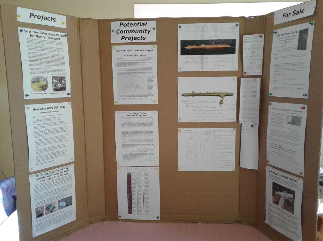 Oops, I neglected to take a picture of my own
display!
Oops, I neglected to take a picture of my own
display!
Anyway here's the "display unit" of posters I had on my table.
(My color laser printer has been making lines across the paper, but
it's not like there's anywhere here to run out and buy a new one!)
The Haida have an interesting history. While many 'red'
and west coast native features are present, it's been said that they
have some Polynesian blood in them, I'm guessing probably dating back
from some Polynesian expedition that chanced to land there, perhaps in
the vicinity of 1000 AD. Evidently in more recent times they used to
raid up and down the west coast of the continent for slaves. But in the
1880s (three centuries after most of North America) 90% were wiped out
by smallpox and only 500-600 remained. Today while there are certainly
some very native looking people there, many of them hardly differ from
white people except culturally. I think I'm pretty white and it's
amusing to have been asked at the Skidegate Co-op Grocery till...
"Co-op number?" "8604." "Do you have a status number?" ...or "Are you
in the band?" (I replied no, I was kicked out because they didn't want
a flute player any more.)
I drove there Saturday in the electric Nissan Leaf. By the
time I had driven the 88 Km to get there, the batteries were getting
down there, and there was only a 120 volt outlet to plug into. I did it
because I knew I had 7 hours to recharge. But the dash
said it would take 14 hours to completely recharge the car. Only a
couple of people went out to look at it, but at least when the M/C, a
lady who must have been a school teacher, asked for a show of hands who
had come by electric car, I was the lone hand. That at least got the
idea into peoples' consciousnesses that electric cars actually exist
and are used. When I went to leave, the dash said seven more hours to
charge, and the estimated range said just 113 Km, which I knew would be
substantially high for highway driving. So I drove home at around 65
KmPH to conserve energy, taking an hour and a half and pulling over a
number of times to let about a dozen other vehicles go by. (Not a good
advertisement for EVs!) I made it with about 21 Km estimated remaining
- a kilometer left before the numbers would start flashing red. That
was a little nerve racking, so on Sunday I drove the Toyota Echo. I was
given a 25$ voucher for gas at Skidegate as a thank you for coming and
bringing all
my display stuff all that way.
Co-op Tidal Project?
There were ideas about "democratic ownership" of energy
production. But the thing that got my attention was a "renewable
electricity generation" co-operative from Vancouver,
"SolShare", in which people could buy shares in a larger solar project
such as putting a large array of panels onto a large building roof, for
500 $/share. They then collect royalties from the power generated. I
wonder how that would work for something more experimental like a tidal
power unit? My thought is that I'd like to try it. Not huge like the
Scottish one. Not a small "demo" project. Perhaps a 100 KW
unit in the north end of the channel near Masset.
At 10 ¢/KWH that could be around 50000-65000 $/Yr.
But because of what BC Hydro pays for diesel power (said to be 50
¢/KWH), it's likely that they would pay 20 or 30 ¢, doubling
or tripling those figures (up to about 200000 $/Yr). Royalties to share
owners would come out of that. Some kind of cost estimate for building
it would have to be created. Shares might be sold on "participate in
promising new technology" as much as for potential returns on
investment. The successes of the Scottish units will be a big help in
selling it since it has now been demonstrated that such designs do
work. If it went well we could continue and do
another one at the other end of the inlet.
Perhaps a two-prong approach would be best: approach the
co-op and see if investors come forth, and
at the same time do small scale experiments with a venturi type unit
towed behind a boat running my "2 KW Piggott" generator. If that looks
promising, do it, and if not, just
go for the large propellers already proven to work. (Hmm... it could
even have a propeller on one side and a venturi on the other for
performance comparison.) And of course press the idea of the
automatic and radio controlled rudder as a unique and valuable
improvement - which it would be. Steering into maximum current
maximizes
power generated, and being able to have the unit come to shore at high
tide so it's beached at low tide should reduce maintenance and repair
costs dramatically compared to having to reach it in a vessel. (See
project details under "Electricity
Generation", below.)
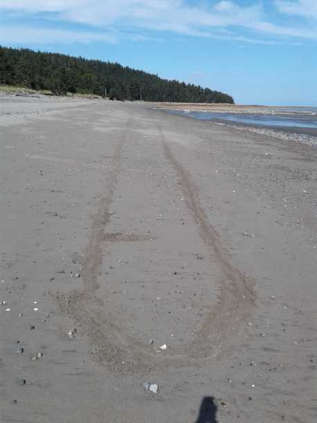 I tried to visualize the size of that Scottish
210 foot
I tried to visualize the size of that Scottish
210 foot
long, 2 megawatt tidal power vessel on the beach. BIG!
In Passing
(Miscellaneous topics, editorial comments & opinionated rants)
Red Quinoa
 A bouquet of red quinoa
As it got colder out I brought some of the quinoa stalks
in and put them in a bucket of water. At first the ones still in the
garden kept growing and turning red as well as those I had brought in,
so it probably didn't make much difference. But it was a nice
September. Later I brought in potted peppers and tomatoes from the
greenhouse.
I must have kept the stalks in the water too long - much
of September - because when I took them out the bottoms were starting
to rot and smelled like a swamp. That didn't seem to affect the seeds.
I got about 3 quarts from my 5' x 7', x 7' tall, garden patch. Once
they were dry, it was easier to roll the flowers between the hands to
get the seeds to fall out, but there was a lot more chaff in them than
in the seeds removed earlier. I may try a couple of things to blow it
out.
 Later I brought the rest in. A few days later I
put it all out on plastic to dry.
Later I brought the rest in. A few days later I
put it all out on plastic to dry.
I think I convinced a couple of avid gardeners to try growing it next
year.
HOW Much
Money?!?
There are financial experts estimating that the USA has
secretly
printed between 21 and 30 trillion dollars
($21,000,000,000,000) over the years, mostly in this millennium.
Apparently it, or much of it, has originated in the "Exchange
Stabilization Fund" and has been filtered out through Department of
Defense contracts and (IIRC) Housing and Urban Development.
Of interest in this connection, on September 10th 2001
Donald Rumsfelt said there was 2.1 trillion dollars "unaccounted for"
by the Pentagon, and that this would be investigated. It seemed
surprising this should be announced on television even if it was true.
The very next day the Pentagon budget office where the financial
records were kept was hit by "an airplane" (by all evidence a missile)
and destroyed. It was claimed that no investigation then was possible.
What this means is that the money shouldn't be worth
anything like what it is presently valued at, because there's far more
of it in or entering circulation than publicly acknowledged and than
most of us know.
Take the 1928 (or 1929?) case of Portugal. To keep the
story brief, a gangster, Simon Riis, had been impersonating a Portugese
bank official, flying to the Bank of England where Portugal's actual
bank notes were being printed, and having them print reams of extra
money "for Algeria" (IIRC), which he brought
back in suitcases and used to buy up Bank of Portugal shares. Oddly,
the Bank of Portugal was responsible for charging anyone connected with
financial fraud. If he could buy the majority of the shares, he could
then choose not to prosecute himself. It almost worked, but as he
bought more and more shares their price went up and up. So he had more
and more Escudos printed. People became suspicious, but as they were
the real printed notes, no counterfeit could be found. And Portugal was
rich and prospering with all the extra money! It was the biggest scam
of the 20th century.
But in printing all the extra money as share prices rose,
Riis made a mistake
and a teller found two bank notes with identical serial numbers. They
had him! The Portuguese bankers realized what would happen if people
found out, and they were inclined to let Riis get away with it. But one
guy just couldn't let it go. He had Riis's wife thrown in jail on some
pretext, and Riis spilled the beans. When it was realized how much
unannounced extra money was in circulation, the Escudo was drastically
devalued, which sent Portugal into a deep depression well ahead of the
general depression of 1929 and the 1930s.
Today, those with first access to these tens of trillions
of secretly 'printed' (if that's the right word any more) dollars can
buy up everything with their much overvalued currency, and have been
doing so. One reason everybody else is poor because we're all selling
things including our labor much too cheap compared to the amount of
actual currency in circulation. Small wonder the US never runs out of
money for its huge military industrial complex and anything else the
"deep state" wants!
Certain things haven't gone up so much, yet. But anything
one can call an investment asset, like stocks, bonds and real estate,
has skyrocketed. The banks and wealthy interests have taken possession
of much of the real estate and rent it out to all those families who
can never, under present conditions, afford to buy a house. And those
who can buy will never ever pay off the gigantic mortgage, so it's much
the same as renting. Husband and wife must both work just to pay the
rent or mortgage, and even many employed people have to get food stamps
or go to food banks
to afford to eat. Half the country is having trouble just making ends
meet. The difference between Portugal then and USA now? Riis was
stopped and that was that. The USA can and will keep printing under the
table. The end result can only be loss of confidence in the money and
hyperinflation. As these multi-trillion dollar "dark money" figures
have only now started coming out into the open, we may be at the
beginning of seeing the dollar's slide into the same oblivion as every
other fiat currency in history.
On the bright side, the government simply creating money
out of thin air doesn't add to the national debt. It's how I've long
advocated that money should be created - for and by the people through
their government, not by a bank as a loan that is then owed back to
that bank with interest. Either way it's still created out of thin air.
If it's by the Federal Reserve or other central bank, or by fractional
reserve lending by regular banks, the money to pay off the interest
doesn't exist. If all the money
in the world were applied to paying down debts, no one would have a
penny except the banks, who would still have oodles of non-existent
money owed to them. So we all, from individuals to nations, become debt
slaves to the banksters.
And some of those with all this wealth, ill-gotten one way
or another, can see what's coming. Bulk bullion dealer Rob Kirby
(interviewed on Greg Hunter on youtube) says there's now "stupid"
amounts of money trying to buy physical gold and silver by the ton.
Bullion is the one investment asset whose price hasn't gone way up -
because
it's the one people measure the dollar against, so it's kept pushed
down at all costs. But there's little to be had. The banks and the
"deep state" have managed to hold the beachball under the water for
quite some time - to keep the best mines from closing, the coin shops
supplied with subsidized ounces and to "buy off" (or intimidate) those
who want to buy too much. But at some time it will pop out.
(Three of the world's top silver mines announced they were
closing 2 or 3 years ago because they couldn't make ends meet with the
current price. Oddly enough, the price of silver suddenly shot up from
14 to 17 $ per ounce, and the mines stayed open.
This month an interesting (if unrelated) story is that a
mining company (Australian?) on the verge of bankruptcy decided to
blast down to a certain strata and found it contained a whopping 70
ounces of gold per ton, an unheard of amount, including the biggest
gold nugget ever found!)
Monsanto
Sellouts: Justice Served?
People have been getting sick and gradually discovering
that it's from GMO foods, especially corn and corn meal products. To
start with, Monsanto invented "Glyphosate"(sp?) as a herbicide, for use
as a weed killer, sold as "Roundup". Then they created GMO strains of
corn that could tolerate glyphosate. Thus, one could spray glyphosate
on the corn fields and it would kill the weeds but not the corn. How
simple!
The trouble was that the "tolerate glyphosate" gene added
to the corn - and to wheat - is harmful to the human digestive system.
People are getting sick and gradually dying. And apparently the rapid
rise of "gluten intolerance" in recent years is also due to the
presence of this gene, and the same "gluten intolerant" people can eat
gluten fine when they visit a country that still has 'indigenous'
strains of wheat and corn. We are eating what might be termed 'tainted'
food. The scientists in the labs told them this would be the case. The
executives who made the decisions decided to go ahead
anyway. They told everyone it was safe. They bullied scientists into
saying it was safe. They got the FDA to approve it (probably in
exchange for money or favors to individuals, who are thereby
complicit). They doubtless reasoned that the eventual lawsuits would
cost less
than the profits from their "special" GMO corn seed and the glyphosate,
and
anyway would come later. They sold their souls for personal gain
without concern for the sickness, unhealth and even death their
egregious plan would inflict on people everywhere.
Now we hear that the Bayer company is buying Monsanto. But
who is selling Monsanto? Who is "getting out" so Bayer can "get
in"? The lawsuits are finally starting to come home to roost. The
individuals who made the egregious decisions of which the lawsuits are
the resulting "blowback" are doubtless the ones who are now "getting
out".
As the anger against Monsanto increases as the general public becomes
aware of what has been done, the perpetrators will doubtless have left
the company and will get off scot free, with all their ill-gotten gains
in their [offshore?] bank accounts. Let Bayer inherit the cauldron of
trouble they brewed up! (And Bayer doubtless has their own plan to
sidestep
it all, "It wasn't us" they'll say, and they're moving the headquarters
to Germany.)
In China, a company put melamine (? I have no idea why)
into baby food products a few years ago. Babies got sick and died.
Never mind the parents having to band together to litigate and sue the
company for eventually proven damages: Those individual
executives in the company who made the egregious decision to do that
were soon tried and convicted, and then stood up against a wall and
shot.
In one case the criminals were removed from the planet by
the authorities and will do no more harm. They will kill no more
innocent babies or hatch further "get rich quick" schemes. Others will
think long and hard before unleashing any similar deleterious program.
In the other the criminals, nameless and faceless to the public, have
walked away with their ill-gotten fortunes to set an example that crime
pays for others to follow, and are free to hatch another evil scheme
themselves. What a contrast! Public outrage and legal action is
mistakenly and impotently directed at the company which they were
running at the time of their crimes.
The future is being thrown to the wolves and the breakdown
of western civilization made certain as it permits all manner of such
sociopaths to continue to live and thrive among us - people with a high
degree of disconnect who have no cares, respect or love for the society
which nurtured them or for the people among whom they live.
-----
As a "bonus" we now find that pollinating insects like
monarch butterflies are dying in droves because of a chemical that is
ending up in flowers, making them poisonous to them. Nicotinoid
insecticides are even worse. Populations of bees are collapsing on a
widespread basis. This will have further serious repercussions to the
food supply.
And Youtube channel "Ice Age Farmer" shows various news
articles which show that owing to droughts, and cold weather into
spring and starting early in fall, the various major crop failures of
recent years have been much worse in 2018 - and have attained to being
a very significant percentage of total worldwide harvests. He says the
mainstream news laughs it off with articles like "Krisp Potato chip
famine in
Ireland", but the warning signs couldn't be any louder, that you need
to grow your own and become food independent. (Get your food stores
together!)
-----
The past tense of "sit" is "sat"
The present tense of "fit" is "fat" (as in, "it used to fit.")
"in depth reports" for
each project are below. I hope they may be useful to anyone who wants
to get
into a similar project, to glean ideas for how something
might be done, as well as things that might have been tried or thought
of... and even of how not to do something - why it didn't
work or proved impractical. Sometimes they set out inventive thoughts
almost as they occur - and are the actual organization and elaboration
in
writing of
those thoughts. They are thus partly a diary and are not
extensively proof-read for literary perfection and consistency before
publication. I hope they add to the body of wisdom for other
researchers and developers to help them find more productive paths and
avoid potential pitfalls.
Electric Transport
Solar Charging for the Sprint Car?
and for the Miles Mini Cargo Van? - New Improved Plan
I had thought 100 watt solar panels would be a great way
to charge the Chevy Sprint and the Miles EV truck. If you put several
together on rails on the roof, you could get just the right voltage,
right? That didn't seem to pan out very well. The Sprint would need
2-1/2 to get enough voltage, and 3 was one too many to fit on the roof.
The Miles would need 5 or 6, which again was a tricky fit. And it
looked like I should make some circuit to shut the charge off when it
was full. So I hadn't actually got around to either project.
But after the 20th when I ordered a crate/skid/palette of
thirtytwo 305 watt solar panels, it occurred to me that one panel
had the same power as three of the 100 watt panels. It was also a
little smaller: 1 m x 1.67 m as
opposed to 3 * 1 m x .67 m = 1 m x 2 m. That would mean it could be
placed on the roof of the Sprint and not stick very far over the
windshield. Much better! The trouble was that as usual the 32 V MPPT or
40 V open circuit weren't quite enough to charge the "36 V" lithium
batteries, which in fact usually sit at about 40.0 volts when not in
use.
Jim Harrington sent me a link to a Chinese solar panel
charge controller/DC to DC converter with flexible input from 12 to 60
volts and a programmable output from 15 to 90 volts, for just 42$. And
a good LCD display to see what's going on. My preference would be to
charge each 12 volt battery as a separate unit, but for the solar the
charging currents wouldn't be too high, and doing the full voltage with
this unit should solve the problem. So I ordered two: one for the 36
volt Sprint and one for the 72 volt Miles.
Measuring showed that if one allowed the panels to stick
over the edge of the truck roof by ~10 cm (4"), the truck could hold
two panels for 400 watts of charging (counting a 2/3 effective
factor since the panels are mounted level and not aimed at the sun). If
it's sunny and you park in the sun, that's headed into some
good charging rate territory. The truck's regular charger only does
around 1100 watts. The charge controller said it was good for up to 600
watts of solar panels. Perfect!
The panels can not only save power grid electricity, but
they give peace of mind that you'll never be completely stuck because
the batteries ran dead. or if the mains power is out for an extended
period. ...at least in the summer.
Other "Green" Electric Equipment Projects
Carmichael
Mill ("Bandsaw Alaska Mill")
I had a bit of an e-mail
conversation with someone where I bought the 3 teeth per inch, 3/4"
wide by .025" thick stainless steel "meat cutting" bands. Considering
the small wheels (10") he said thinner was best, and he thought I was
making the best choice of the limited selection available.
But if the saws get into production, I expect we can have
more optimal .025" bands with coarser teeth (2 teeth per inch or lower)
made to meet the new demands for a new type of saw. I'd rather the
bands can be bought in stores or broadly sourced rather than only be a
custom order from the bandmill maker.
As mentioned in the last newsletter, the 3rd and 4th were occupied
finishing cutting up the main two 10' sections of the alder tree I
felled in August. It was much easier to cut than the spruce and I was
quite pleased with the results and the performance of the mill.
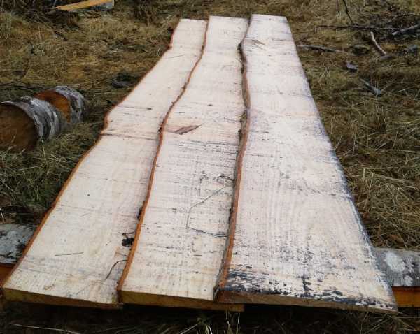
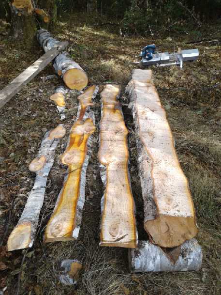 Cutting lumber from the alder tree logs
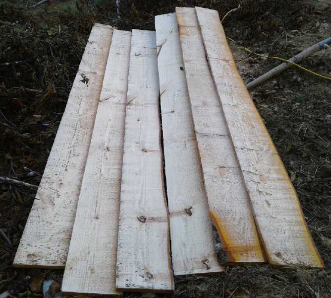 Boards from the upper section
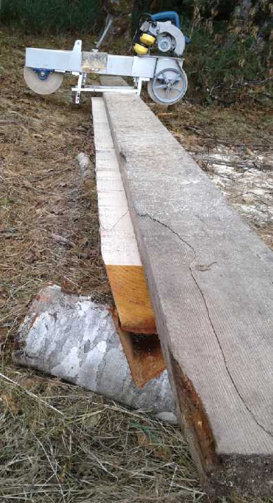 Cutting beveled siding from the bottom section.
The smooth edge started vetical at 90° but got more
and more angled with each angled cut.
 Some of the beveled siding.
If I'd had it planned, I would have made it 12' long instead of 10', to
make
siding for the roof over my travel trailer, which has posts 12' apart.
Well, there's lots more alder if I want to cut and mill it!
6th: After such good results with the alder, cutting up
two sections of log into about 20 nice straight boards in good time, I
returned to the spruce, to tackle the 10" wide cut I had set up
earlier. It went badly. The band cut inverted bowls and curves and got
hot. I tried a number of things to improve it. The only thing that
really seemed to work was increasing the band tension a lot. And even
that seemed to be a half measure. I tried starting again from the other
end, but it didn't go any better. I couldn't get through it. Not one
board! What a let down after cutting up a whole alder log into about 20
pieces of fine lumber in 7 hours! I finally went out again, determined,
and eventually got through it. What a wasted day.
So I conclude that there is indeed a great difference
between different species of wood. Also the alder was freshly cut down,
while the spruce had been down over a year. That too can make a
difference. I should probably stick to 4" and 6" wide cuts in the
spruce, while some cuts that went fine in the alder were 10" or even
11".
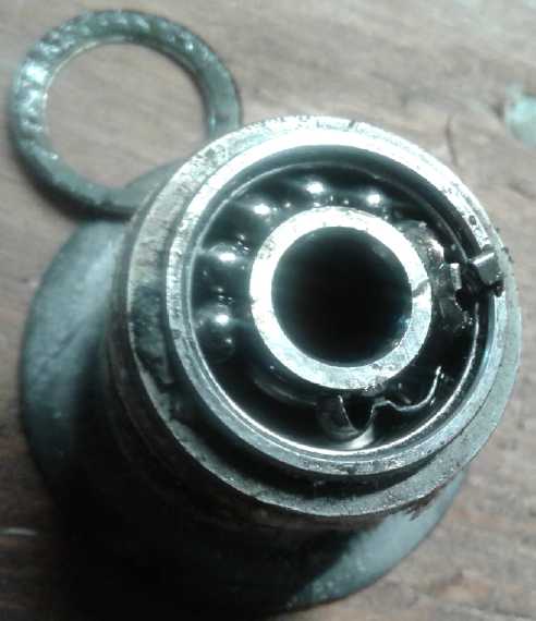
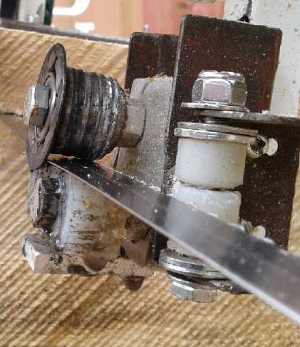
But there were problems. First, the blade was dull.
Second, a bearing seized in a guidewheel and had to be replaced.
Third the spring holding the plastic against that guidewheel managed to
spring over sideways so it wasn't strongly pressing the plastic against
the wheel. Once again a gap was opening up insead of the band tracking
properly. I replaced the bearing, and I drilled a shallow hole in the
aluminum bottom plate for the spring so it couldn't do that again.
What I seemed unable to do was sharpen the band very well. I got out a
magnifying glass and it showed that the diameter of the diamond
cylinder was a little too small. It was grinding up to but not quite
getting the dull cutting tip. Furthermore, the nylon had been chewed
off and the band had hit the bolt and the backs of the teeth just
behind the tips were flattened off. The backs needed to be filed down
to an angle again for it to work right, too, and I didn't manage that
with half of them. A diamond card I have wore out.
I wasn't very happy with the tube of little ball bearing
races I'd bought for the band guides. They seemed to be jamming and
breaking one by one. One thought is that thought they probably aren't
intended for transverse loads. With the "railway wheel" band guide
wheels, the band pushes on the bearings sideways, perhaps explaining
this broken one. But some that had never been used in those had broken
down or become hard to turn, too. Perhaps I should find some very small
needle bearings?
Someone later said that spruce was about the hardest thing
to cut, having criss-cross interweaving grain. If it could cut that, it
could cut most anything. On the 8th I tried again, this time taking a 2
to 5" slice off the edge of the same cant. It didn't cut well, so I put
on my last new band.
Two cuts, with the widths increasing as I went down, went
great! The new, really sharp blade was certainly what it needed.
Who named a big long block of wood a "cant", anyway?
Between "knot" and "cant", it all starts to sound pretty negative. A
more negative word however is "nail". 5 inches into the third cut. Now
that I was out of the city I thought there wouldn't be any, but there
it was inside with the tree having grown over it. Per my usual I not
only hit the nail, I had to be ripping it lengthwise. 3/16" higher or
lower I'd have blissfully missed it, perhaps none the wiser about its
presence. Now the fabulous brand new band, the last one of the three I
got, wouldn't cut anything.
I wouldn't be cutting again until (a) I ordered and
received some new bands, (b) I found a much better way to sharpen the
ones I had or (c) I could try the .032" regular band that I still have
from before I raised my shop bandsaw with a wooden block, after which
it needed 105" bands instead of 93". The "regular" .032" x 3/4" band
was 2 teeth per inch. I thought it was a little thick for wrapping
around 10" wheels instead of 14", but I decided it would be a good
thing to try out anyway, and see how it worked.
It became apparent that what I most needed was a practical
way to effectively sharpen the bands. On the evening of the 11th I took
two and inspected them under a magnifying glass. On one the edges of
the teeth were well rounded off. Definitely dull. (That's probably the
one I cut up the alder with, but I wasn't keeping track.) The other
looked pretty good to me. Why did I take it off? I put it back on the
saw. I also looked at a few ideas on line for how to sharpen bands.
There were simple things like "grind down the backs with a Dremmel
tool" (on slowest to minimize heat!), to elaborate jigs that moved from
one tooth to another with a powered ratchet as a grinding wheel touched
up all the faces of each tooth as it moved.
When I tried to saw another board it didn't go very well.
I was disappointed. It didn't seem to cut very well to start with, and
soon little sawdust was coming out as I tried to cut further. On this
band the teeth seemed to keep clogging up with sawdust. I used a wire
brush to clear them - three times - and eventually got to the end. When
I looked at the piece underneath I found the reason: just 3-1/2 inches
in, I had hit another nail! And again not just a nail: I had sawed
diagonally right through the head. So once again, unknowingly, I had
been cutting with a dull band. And it was the last one that seemed
pretty sharp.
I had already cut 6" off the end of the log with the
chainsaw. This nail was higher up. No wonder I couldn't figure out the
metal detector readings previously - there were actually two
nails near each other. Or were there even more?
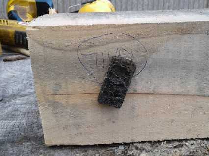
This time I got out a supermagnet. As soon as I put it
next to the wood it jumped to another nail just under the surface! That
seemed to be it... three nails ...at least, near the surface. I cut
that piece off. My cant was a couple of feet shorter now. Of course if
I'd known I'd have cut it shorter before wrecking two bands.
Apparently the first picture is a "find the
nail" puzzle.
The next one is a supermagnet 'stuck' to an unseen third nail inside
the wood.
Automatic Band Sharpener
This was getting really discouraging! I looked at
bandsaw sharpening jigs and tools on line. There was a wholly automatic
one for 1300 $. It apparently only did wider bands with a longer tooth
pitch - around one tooth per inch instead of three. But it had many
adjustments and I thought it could probably be made to work. It might
skip every second tooth, but if so I could do it twice, offset by a
tooth the second time. The price was (I think) more than all I've spent
on the entire bandsaw project so far in all these months. (In fact,
it's more than the 1200 $ I spent making my entire pivoting blade
sawmill in 2006.) OTOH, I really need to be able to resharpen bands if
I'm going to mill lumber, and I don't want to spend half my time
sharpening them.
From a youtube video, it seemed this was the same
sharpener as the one sold by woodlandmills.ca . I looked there and they
were "only" 849 $ there. I ordered one. (total 933 $ with tax and
shipping. Yikes, did I really do that? I'm running short of money with
almost no income.)
On the 14th I visited someone who made arrow shafts. He
had several bandsaws and explained some details about bands and
sharpening and stress cracking. "Heat is the enemy of bands." A
reminder of what I already knew.
That evening, I tried sharpening another band with the
diamond bit in the 'dremmel'. It was one of the older thinner .022"
bands. It seemed to go on forever and I took a break in the middle. The
next morning I put it on the mill. It cut nicely for a couple of feet,
then started slowing down and cutting curves. It must have been one
that had been overheated and lost the tempering of the teeth, so it
didn't stay sharp long. There was a big waste of time - and one band,
at least, for the garbage can!
I ordered another 5 bands. The website said they would
take four weeks to produce. That was unexpected since the first ones
had only taken a week to arrive, and most unwelcome. By the time I got
them it would be November and cold and miserable outside. Maybe the
sharpener would arrive sooner. In the meantime, that was it for milling.
The sharpener arrived on the 27th. By then I was heavily
involved with preparations for the Energy Symposium and didn't even
have time to open the box.
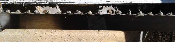 Spruce shavings buildup on a dull band
Improved Piggott High Efficiency Axial Flux Alternators
With no iron in the stators and hence no iron losses and
absolutely no magnetic cogging or friction, and permanent magnets in
the rotor and hence no energy wasted in field current, and high
magnetic coupling for high output at low RPMs, I chose to build the
Piggott design because it appeared to be the absolute best of all
generators.
But Piggott said they were only good in homemade
windplants for around 500 watts (at only ~300 RPM!), or up to 1000+
watts (~425 RPM) for short periods. That didn't seem like much "bang
for the buck" for all the magnets and wire. The reason for the low
capacity however was not electromagnetic but simply that there was no
cooling designed into it. I thought that if it was supplied with air
cooling and the coils were better exposed to the air flow, it would
probably be good for at least 1500 and perhaps 2000 watts, still at
under 1000 RPM.
Making Rotors and Stator
Pursuant to getting the project going again, I was
gradually gathering up the parts and jigs and molds as I ran across
them in scattered places wherever they had been stored after I moved. I
couldn't find the stator mold. Finally I looked it up in TE News #108,
January 2017. The picture showed it was made of black speckled plastic,
not white like most of my molds. With this info, I soon located it
right where I had first looked. How fickle memory is for detail! Later
(8th) I looked there again to see how many turns of wire I had wound in
the coils. (21 but they took too much room so I unwound two turns,
making it 19.) It was the last project I physically worked on in
Victoria before I was out of time and had to get packing to move. I had
designed the stator and made the mold, designed and had four 30 cm
diameter steel magnet rotors cut by abrasive waterjet (for two
generators or one extended one), and wound 2 of the 9 coils. At the
bottom it said "To be continued at Lawn Hill." So here it is!
The mold was only about 10 mm thick. I started wishing it
was thicker and for the first time missed the CNC drill-router I had
left behind. I could have made another layer for it. As it is, I would
have to do all the work of setting up the new CNC router and finding
all the right sets of software for it before I can make anything more
like that. That would be another whole project - ugh!
Having not got to it for quite a while I had earlier
offered the parts to make one generator (I had enough for two) to an
off-grid farming family that seemed
very interested. I said all they had to do was send me pictures of the
construction and installation (micro hydro) for my newsletter. I said
they could work in my shop if they wanted and I would show them what to
do. Here, perhaps, was a chance to get others involved to finish this
one project, for their own benefit, and not have to do everything
myself. Somehow after visiting twice they seem to have let the idea
lapse. (I shouldn't have opened my mouth the second time and remarked I
might need one myself for a floating tidal power project. OTOH they did
say at the start they'd rather buy one than build it.)
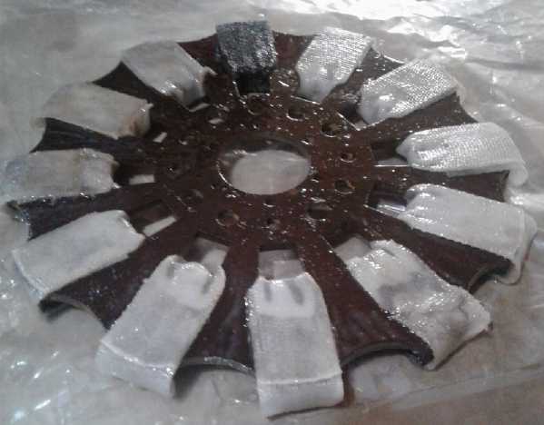
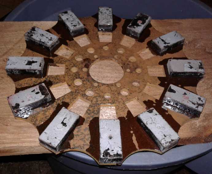 Used supermagnets/NIB/NdFeB/rare earth magnets
epoxied onto custom steel rotor
Used supermagnets/NIB/NdFeB/rare earth magnets
epoxied onto custom steel rotor
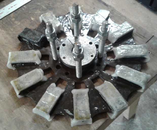
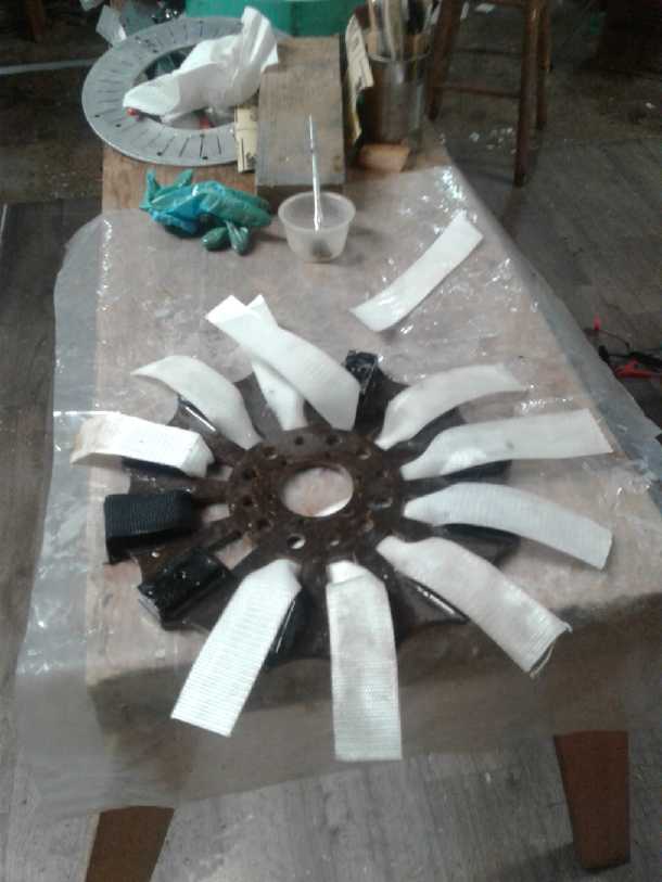 On the 6th and
7th I got back to it and put the epoxied strapping on the magnet
rotors. I trust they'll be good for up to about 2000 RPM. It was extra
work to do the two rotors where
for my motors only one was needed. But it should be worth it to have
super efficient generators with no cogging or magnetic friction. One of
the rotors all ready to go (without hub) was 4143 grams.
On the 6th and
7th I got back to it and put the epoxied strapping on the magnet
rotors. I trust they'll be good for up to about 2000 RPM. It was extra
work to do the two rotors where
for my motors only one was needed. But it should be worth it to have
super efficient generators with no cogging or magnetic friction. One of
the rotors all ready to go (without hub) was 4143 grams.
Putting on the polypropylene strapping/webbing
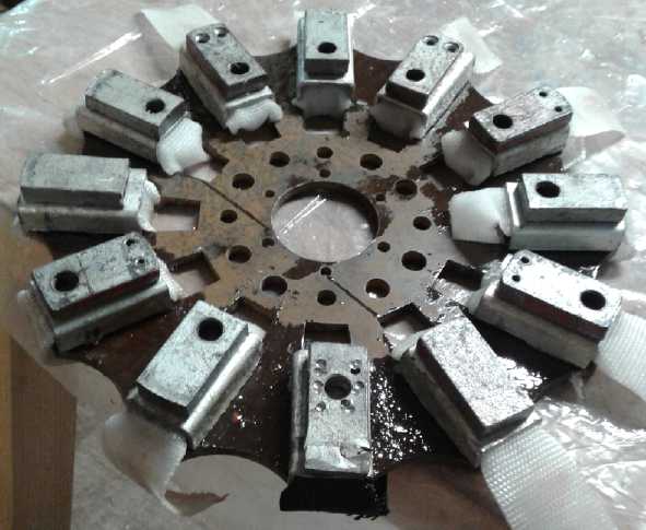 Aluminum "U" pieces hold strapping onto magnets,
and steel weights clamp them down magnetically
so it doesn't stick up.
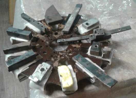 Weights to hold down the strapping while the
epoxy sets
Weights to hold down the strapping while the
epoxy sets
A rotor done (magnets down)
Later I found that the
generator actually met Piggott's specs and realized it would never be
run over 1000 RPM. That made the strapping superfluous except as extra
tough magnet protectors. Basically it was a lot of extra work for
nothing, and it forced the magnets to be an extra 1/16" away from the
stator.
 On the 8th I
wound a coil and on the 9th two more. It was a lot of extra work
winding three parallel wires instead of just one, as well as painting
each layer with epoxy as I wound. (And reusing old magnet wire
from an early Electric Hubcap motor also made it harder. I ran out of
that before I finished all the coils.) Oh well, 5 down and 4 to go!
Then I discovered that I had
done one wrong. I had made two sets of coil centers for winding them.
One was just 10 mm thick, the other was 1/2". I had decided to use the
1/2" ones, but somehow I accidentally used one of the thinner ones for
this one core. That made it bigger in diameter than the others to get
19 winds on it. Oh well, I'd see if I could get it to fit in. Otherwise
I had one more to wind. And with my winding setup I found I had coiled
one or two "counterclockwise" compared to the others. I decided no
matter, I'll just wind all three coils of that phase the same way.
On the 8th I
wound a coil and on the 9th two more. It was a lot of extra work
winding three parallel wires instead of just one, as well as painting
each layer with epoxy as I wound. (And reusing old magnet wire
from an early Electric Hubcap motor also made it harder. I ran out of
that before I finished all the coils.) Oh well, 5 down and 4 to go!
Then I discovered that I had
done one wrong. I had made two sets of coil centers for winding them.
One was just 10 mm thick, the other was 1/2". I had decided to use the
1/2" ones, but somehow I accidentally used one of the thinner ones for
this one core. That made it bigger in diameter than the others to get
19 winds on it. Oh well, I'd see if I could get it to fit in. Otherwise
I had one more to wind. And with my winding setup I found I had coiled
one or two "counterclockwise" compared to the others. I decided no
matter, I'll just wind all three coils of that phase the same way.
I wound another one on the 11th. Two more on the 12th and
the last one on the 13th. 6 coils in 6 days! I would definitely have to
find an easier way next time. Maybe I'd just use my heaviest (#11)
magnet wire, wind until it looked like the right size, and work with
whatever voltage came out - 1.5 times whatever this one was. Then
again, there's just one spool of #14 AWG, but I have lots of #15 and
#16 wire, and it's free until I run out!
On the 15th I screwed all the coil centers into place in
the mold complete with coils. Being wound mostly with used wire there
were slightly different sizes, and I contrived to avoid having to wind
a new one by putting the smallest coils on each side of the extra fat
one wound on the thinner center. The wires on those and one other coil
gap touched, so I put tarpaper between them.
I actually did it twice: once to make holes for the screws
in the right places, having marked them on the plywood in early 2017,
and then again with a sheet of polyethylene underneath so the finished
stator won't be stuck to the plywood.
On the 17th I
soldered all the wires together and arranged them as neatly as I could.
The wiring always take up more room than I bargain on. I left all 6
ends sticking out, 2 from each phase. That leaves the option of wiring
it "delta", or making the "Y" point "ground", if the voltages from "Y"
configuration are greater than desired. It was well that I did because
I had to reverse the ends of the phase wired counterclockwise. I drew
the waveforms - of course it mattered! Duh!
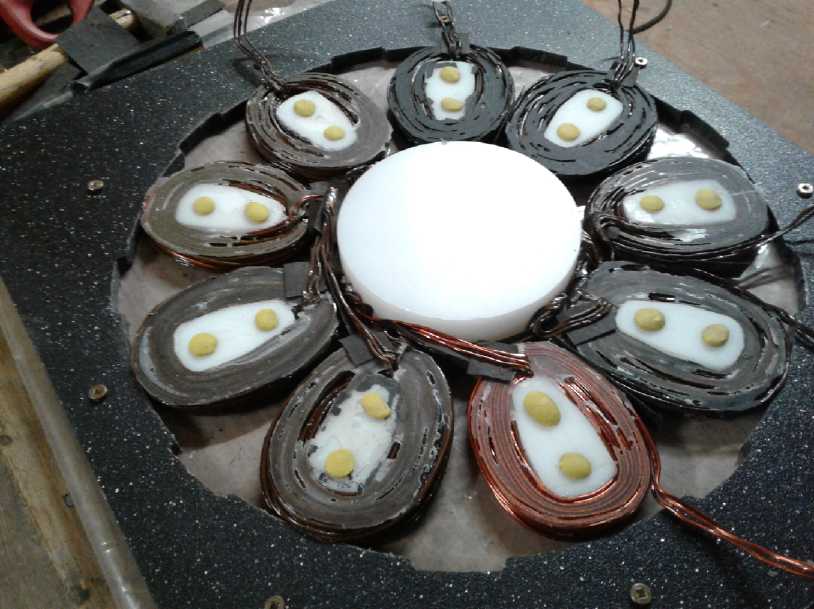 Ready to Fill
 The table
proved to be not quite level so I carefully leveled the mold by sliding
a couple of things under its plywood base. Then I poured epoxy into the
mold. The mold was only 10 mm thick and filled to about 9 mm, whereas
the coils were 1/2" - 12.7 mm. The next morning I looked. Should I
leave it like that? With some coil edges sticking out, the cooling
would be best. But it was pretty thin, and the wires were weak spots. I
wouldn't want it to vibrate magnetically while making power and perhaps
break.
The table
proved to be not quite level so I carefully leveled the mold by sliding
a couple of things under its plywood base. Then I poured epoxy into the
mold. The mold was only 10 mm thick and filled to about 9 mm, whereas
the coils were 1/2" - 12.7 mm. The next morning I looked. Should I
leave it like that? With some coil edges sticking out, the cooling
would be best. But it was pretty thin, and the wires were weak spots. I
wouldn't want it to vibrate magnetically while making power and perhaps
break.
 I undid the
screws holding the outer mold and pried it up all around the edges,
working around the edges and inward with two chisels until it came
loose everywhere and was level with the tops of the coils instead of
the bottoms. (The coil centers were still screwed down, and as I hoped
the coils and the epoxy casting stayed right in place.) Then I mixed
more epoxy and filled it up so it would all be 1/2" thick like the
coils. I would have put in wads of polypropylene cloth to give it more
strength like on my motors, but there really weren't many places to put
it, and with no top on the mold to press them in it would have just
been a mess.
I undid the
screws holding the outer mold and pried it up all around the edges,
working around the edges and inward with two chisels until it came
loose everywhere and was level with the tops of the coils instead of
the bottoms. (The coil centers were still screwed down, and as I hoped
the coils and the epoxy casting stayed right in place.) Then I mixed
more epoxy and filled it up so it would all be 1/2" thick like the
coils. I would have put in wads of polypropylene cloth to give it more
strength like on my motors, but there really weren't many places to put
it, and with no top on the mold to press them in it would have just
been a mess.
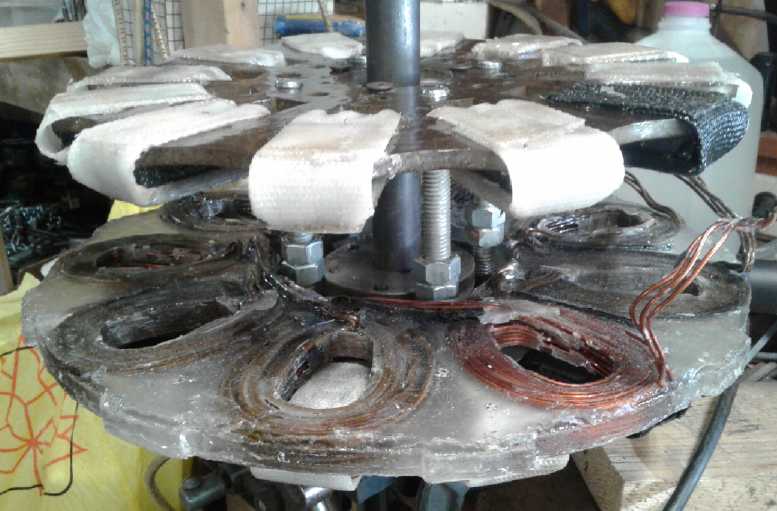
It should perhaps be pointed out that the magnets on the
rotor spin around in the area of the white coil centers. The metal
rotor is farther away by the thickness of the magnets, leaving room for
the wiring to stick up a bit as it does.
Finished stator "side A"
Stator from the other side
Making a Housing
On the 19th, having made the rotors and stator, I finally
started thinking about a housing to put them in. The large diameter
(350 mm) end plates had to hold the bearings solidly in the middle,
especially if I used cup & cone "trailer wheel" bearings. I'd
probably be better off to use needle bearings. I started thinking about
making the plates out of plywood, and wished I had a lathe big enough
to turn 14" discs. But should they be discs? How about an upside down
"U" (or "n") shape, perhaps with mounting flanges sticking out the
sides? The cover could also be that shape, with a separate flat bottom
piece.
Then, the end plates would be out of the field, but a
metal cover over the center would cause magnetic drag and heating. It'd
have to be plastic. But plywood end plates with a coating of
"flameproof" paint seemed more and more attractive. One could even just
make it a plywood box. Why not? It would be in a room or in some sort
of outer housing with other components. It couldn't be waterproof or
streamlined or weather resistant and suck in cooling air too. End
plates sounded like a good use for my 3/4" birch plywood.
All I managed to accomplish that day was to buy a sheet of
1/4" birch plywood to match the 3/4", and dig out a 1" shaft and two 1"
center, press fit housing, needle bearings from a couple of cluttered
drawers. (Yay, I actually had them!) That meant I seemed to have pretty
much everything and all I had to do was figure out where to cut and
drill, and build it. I did that, except for a few finishing touches and
paint, the next day. I had intended the top half to be shaped, but when
I got there it looked like the simple thing to do was just to make it
square. The only thing I used the thin plywood for was the top cover.
(And later I thought that would be insufficient safety if a magnet did
fly off the rotor, and changed the top to 3/4" too.)
 I made the
holes for the bearings with a hole saw that seemed about the right size
(1-3/4"?) and a tiny bit of filing at an angle made them perfect for
the pressed fittings. They weren't quite in line horizontally, but it
was level, and bearable. Later I figured out that instead of just
measuring with a ruler, I should have lined the two pieces of plywood
up one on top of the other, clamped them together, and drilled the
center bearing/shaft pilot hole right through both of them at once.
I made the
holes for the bearings with a hole saw that seemed about the right size
(1-3/4"?) and a tiny bit of filing at an angle made them perfect for
the pressed fittings. They weren't quite in line horizontally, but it
was level, and bearable. Later I figured out that instead of just
measuring with a ruler, I should have lined the two pieces of plywood
up one on top of the other, clamped them together, and drilled the
center bearing/shaft pilot hole right through both of them at once.
 Holding the stator in place,
with one rotor, I spun it up to ~100 RPM by hand just by twisting the
shaft. I could feel the breeze coming off the rotor - a good sign for
cooling. It put out less than a volt AC from one phase. Might I end up
running it at a faster RPM than I thought? I shorted it and got 2.4
amps at about 50 RPM, which was as fast as I could get it to go with
the magnetic drag from the short. (Maybe I should make a crank handle?
But later I put a large V-belt pulley on it for real testing.)
Holding the stator in place,
with one rotor, I spun it up to ~100 RPM by hand just by twisting the
shaft. I could feel the breeze coming off the rotor - a good sign for
cooling. It put out less than a volt AC from one phase. Might I end up
running it at a faster RPM than I thought? I shorted it and got 2.4
amps at about 50 RPM, which was as fast as I could get it to go with
the magnetic drag from the short. (Maybe I should make a crank handle?
But later I put a large V-belt pulley on it for real testing.)
The finishing touches it still needed were ventilation
holes for the air flow cooling, and a flameproof paint for safety.
Later!
Assembly
 On the 22nd I
tried putting together the two rotors with the stator in between. This
is a tricky operation because the rotors attract each other and if
given the chance will clamp together with crushing force. I had put in
three options for four bolts to have them thread together: four 1/2"
holes around a 4" diameter circle, four 12 mm holes in a 200 mm
diameter circle, and 3/8" holes also in the 200 mm circle, making 12
holes near the center spaced the same as car wheel lug bolts.
On the 22nd I
tried putting together the two rotors with the stator in between. This
is a tricky operation because the rotors attract each other and if
given the chance will clamp together with crushing force. I had put in
three options for four bolts to have them thread together: four 1/2"
holes around a 4" diameter circle, four 12 mm holes in a 200 mm
diameter circle, and 3/8" holes also in the 200 mm circle, making 12
holes near the center spaced the same as car wheel lug bolts.
I threaded the 12 mm holes to take 1/2" bolts, which I
made from 4.5" threaded rods with two nuts screwed together on one end.
I ground a 7/16" "hex head" onto the thin end so I could turn them with
a nutdriver. I put the rotor with the shaft in a vise so it couldn't
jump up at me when I brought the other one near, and held the one with
the bolts - with my fingers between the magnets and not on them, just
in case.
But when I tried to put them together, the nuts fit tight against the
SDS hub and the bolts wouldn't turn.
Then I thought it wouldn't matter: I could do it without
the nuts because the 1/2" bolts wouldn't go through the 12 mm
unthreaded holes in the other rotor. In this I was wrong again because
the bolts lined up with the 1/2" holes in the other rotor instead of
the 12 mm holes. Three of the bolts went through the holes, but for
some reason the fourth didn't quite line up, which prevented the rotors
from snapping together against the stator, which I hadn't actually
thought was possible... but still I held the rotor with my fingers
between the magnets. If they had snapped together, I'd have
been really thankful I took that precaution!
I started thinking of carriage bolts whose large heads
wouldn't go through any of the holes but which wouldn't hit the hubs,
but I didn't have any the right size. Then it occurred to me to line
the rotors up two magnets over. Then the bolts would be against the
3/8" holes instead. I got it put together and put it into the back of
the chassis with the shaft in the rear bearing. I put a couple of 3/8"
bolts through both rotors to be sure they couldn't twist against each
other and the 'outer' one jump over by two magnet places compared to
the one solidly attached to the shaft. (...that rotor I suppose should
have a shaft key, too. Sigh!)
Next it needed some pieces to fasten and adjust the
position of the stator. It had to be held right between the two rotors
without touching either of them as they spun. And it had to resist
turning itself as the magnetism tried to drag it around. Since the
rotors spin from the center axle, the stator can only be held from the
outside, and I had sized the box so it came up to the top, bottom and
sides. I cut some small pieces of plywood to hold it and screwed them
into place. I ended up gluing a couple of bits in to adjust the
position. That needs a better system!
Finally it needed for the wires to come through the box
and preferably connect to a terminal strip. Since I didn't have such a
big terminal strip, they would just have to stick out. If it's to be
rectified to DC per the plan for this one, a six diode assembly on a
heatsink and screwed to the case can take the place of a terminal strip.
 By evening
everything was assembled. It occurred to me that if Piggott generators
could do 500 watts at 300 RPM then they could do 2000 watts at 600 RPM
and 4500 watts at 900. There's no way (I don't think) the cooling will
be adequate for 4500 watts, so that means the top RPM can be limited to
under 1000; even to 800. For those speeds, it's probably superfluous to
have all that strapping on the magnets. Simply epoxying them to the
rotor should be sufficient, with maybe an extra coat over the top for
extra strength and to protect the magnets. I could simplify the rotors
with fewer and bigger cooling holes, making them that much simpler and
cheaper to have made, and more especially it would greatly reduce the
labor, making a production version seem more worth while.
By evening
everything was assembled. It occurred to me that if Piggott generators
could do 500 watts at 300 RPM then they could do 2000 watts at 600 RPM
and 4500 watts at 900. There's no way (I don't think) the cooling will
be adequate for 4500 watts, so that means the top RPM can be limited to
under 1000; even to 800. For those speeds, it's probably superfluous to
have all that strapping on the magnets. Simply epoxying them to the
rotor should be sufficient, with maybe an extra coat over the top for
extra strength and to protect the magnets. I could simplify the rotors
with fewer and bigger cooling holes, making them that much simpler and
cheaper to have made, and more especially it would greatly reduce the
labor, making a production version seem more worth while.
I wired it "Y" and got it up to about 120 RPM by hand. It
put out about 3 volts. So it should be 15 volts at 600 RPM. That seemed
a little on the low side. A single #11 AWG wire for the coils might
give about 28-30 turns instead of 19, so 23 volts at 600 RPM. Again for
production the single wire is much the easiest to wind. Or it could be
57 turns of single #14 AWG wire, making 45 volts at 600. If I'm
producing, customers can (within limits) have whatever they want. (But
I wasn't thinking... When all three phases were rectified to DC it
would be square root of two higher voltage, 21 volts DC rather than 15.)
I shorted two phases and managed to twist the shaft and
get around 4 amps. Lacking that handle, I put vise-grips on the shaft
and got up over 8. If I shorted all three phases together, it was hard
to twist the shaft. And when I stopped twisting, the generator came to
an 'instant' stop.
I might have run more tests, but that was sufficient and I
had to get ready for the Swiilawiid Energy Symposium.
Testing
Generator Performance Graph from Hugh Piggott's
book, How to build a Windplant, 2004 edition
On the 25th
after making a few adjustments to stop things from rubbing, I put a 12"
V-belt pulley on the shaft, and a ~2" one on my radial arm saw, and
spun up the generator with the saw motor. It put out a whopping 7.2
open circuit volts AC from one phase, at 52 Hz. With 6 magnet reversals
per rotation, the speed would have been 52/6 * 60 sec/min = 520 RPM.
(The Hz reading times 10. Duh!)
I connected the phases in "Y" and measured phases open
circuit A-B and A-C as 14.4 VAC. B-C however was 15.1 volts. That means
phase "A" is short a winding or two on one of the coils. I must have
miscounted, or I unwound a loop from the one that was too big in
diameter to fit it in.
Then I shorted between two phases and tried two clamp-on
ampmeters. They both said about 46 amps short circuit (I think it was
phases B-C). When I turned off the saw, everything stopped in an
instant. (That's how all those quick-stop power tools work - the switch
in "OFF" shorts out the motor.)
I thought I should try again and measure the RPM as well,
because it was probably lower. I used the third phase to get the
frequency. I was holding the V-belt tight by pushing back the saw
handle. I guess I pushed harder. This time I got 62 amps and 27 Hz -
just 270 RPM. The belt must have been slipping a lot. (If it hadn't
been it probably would have stalled my saw motor.) 62 amps? If it was
really 62 amps, even after a few seconds the alligator clip wire should
be hot. Sure enough it was still quite warm and one of the clips was
hot. I guess it really was 62 amps!
Of course with a proper load, the voltage would have been
loaded down and the current would have been less. and the RPM in
between. Open circuit voltage at 270 RPM would have been 270/520* 15.1=
7.8 volts. If we roughly estimate "maximum power point" would have been
6 volts and 45 amps, that would have been 270 watts. That's at the
lower end of what Piggott's graph shows at 270 RPM, but not far off.
Factors that could make it a bit lower are: 1. The steel
was bowed a bit so my rotors weren't quite flat, so they had to be a
bit farther away so as not to hit the stator, and 2. the polypropylene
strapping on my magnets also forces each rotor to be 1/16" farther from
the stator, and 3. my rotors are just slightly smaller in diameter, 300
mm versus 1 foot (305 mm).
But in writing the above paragraph there was something I
forgot: I'd only connected and measured between two phases. Once all
three phases are rectified to DC, the voltage will be square-root-of-2
higher with proportionately higher available DC current and power for
any given RPM. That's very encouraging. Apparently my original winding
calculations for useful voltage in 2016 weren't so far off after all.
So performance should be on the top line of Piggott's graph or even
exceed it. I didn't have time (or enough high current diodes) to try it
out this month. But it was gratifying to realize that the performance
is/will be "as advertised" in the performance graph that made me
originally want to make one; that my unit will achieve similar results
at around 300 RPM as the originals. And of course it should be able to
go up to 600-900 RPM and put out probably a couple of kilowatts - maybe
even more? - continuous. Even 1 KW continuous would make it the best
one ever built.
From now on I won't put the epoxied strappings on. It
isn't needed at such low RPM.s. Then it will do as well at even
slightly lower RPM.s.
What to use it for? - VAWT, Tidal Experiments
So I have perhaps the best generator ever, to connect to
any source of mechanical rotary power. Obviously a prime use for them,
for me, is to sell them. But before that, the first one should really
be tested thoroughly. I thought my Electric Hubcap motors were ready to
sell before testing disclosed the need for several further strength and
safety improvements.
I had been gathering, and the Swiilawiid Energy Symposium
pretty much verified, that no one has tried a vertical axis wind
turbine ("VAWT") around here. I think these should work better than
horizontal propellers in gusty and shifting winds, which is what most
of us on the BC coast have if we can't put a tower well above the tall
tress. They don't have to keep swinging around as the wind changes
direction. But someone mentioned seeing one where the blades swing out
and shut off the unit if the wind speed is too high. That sounded
intriguing. I might just make a demo unit with the PVC pipe segment
blades that I made 2 or 3 years ago, either fixed or, if it seems
simple enough, with some sort of overspeed reduction/shutoff. Just for
something to power up the generator.
Then maybe some sort of demo experimental tidal flow power
unit - towed behind a strong motorboat to get a good set of figures for
various flow rates - that will actually make kilowatts to really
harness the generator's full capacity. At the same time, I want to test
the venturi flow capture idea, so I'll put those ideas together.
Saving Mixed Epoxy for Later
Conventional wisdom says once epoxy is mixed it all has to
be used; it all sets whether applied, on the brush or still in the
container. But it sets very slowly at low temperature. Mostly around
here with the temperature in the "teens" Celsius it takes many hours
(and I didn't bother putting them in a warm oven), which is why my
coils were wound over a period of days. When I have mixed epoxy left
over, I put it in the freezer. In my old freezer in Victoria, I could
still use it a day later. In two days it was pretty thick like taffy,
sometimes still usable.
An interesting thing I noticed: This freezer is colder,
about -22°c instead of -18. It keeps food better longer. After I
epoxied the magnets onto the rotors I left a little tub of epoxy in it
for 6 days, and it was (just) still workable! And the little "glue
brush" too. I used the same one I started with on August 31st for the
whole project, albeit it soon became a sort of a fat wad on a metal
stick more than a brush.
Note that that's not a reason to mix extra and think to do
it all with one batch. If there's very much in one mass for very long
it will self heat, perhaps even in the freezer. In this thermal
runaway, it reacts faster as it gets warmer, which generates more heat
and it sets even faster. After starting to feel warm it will very
rapidly get too hot to hold, harden in seconds, and often it will catch
fire. (That goes for polyester resin as well as epoxy.) That's not
good for your freezer or your house.
Manufacturing?
Well, I now had interest in two of the generators -
potential customers! Can I make them and offer them for a price that
people are willing to pay? The first place I went to was otherpower.com
, because I remembered they made and sold Piggott stators among other
components, which would be similar enough to mine that it might be
easier to buy them. The big difference in my improved version was the
magnet rotors. I hadn't been there in some time... apparently quite a
long time... because it said owing to the Colorado floods and forest
fire of 2012, their shop was so damaged they couldn't make components
any more. Okay, I'm on my own! I cleaned the epoxy off my stator mold
for next time.
At first I was thinking of waterjet cut aluminum end
plates... but why not just a plain plywood box even for the production
model? Give it a coating of flameproof paint. Easy for the customer to
screw to something or drill bolt holes into for custom mounting. I
could easily make them myself as needed and for the lowest cost.
Then I started thinking it would be really nice to make
square(ish) stators. They'd be easiest to mount in the square box and
would be solidly wedged against turning forces. That again brings back
the spectre of needing to get the CNC router working to make a new
stator mold.
If I was going to do it, I should not only take the sample
just made to the Swiilaiid energy symposium but also brochures for
people to pick up... with a price on them. I started thinking about
what to charge. It had to be worth my while, but not a price people
wouldn't pay. What were the materials?
ROTORS
2 - 12" rotors custom cut by abrasive waterjet (150$)
24 - 1" x 2" x .5"
'supermagnets'
(225$)
1 - SDS (or H) taper lock hub
(25$)
1 - weld-on hub
(15$)
4 - 4.5" x 1/2" hex head bolts
(10$)
6' - PP Webbing/Strapping
(5$)
(Total 430$)
CENTER
1 - 1" x 10" shaft
(10$)
2 - 1" I.D. press fit housing needle
bearings (40$)
(Total 50$)
STATOR
1 - pile of magnet wire (I think I'll see how many turns of #11 would
fit and just go with a single wire on each coil.) Voltage can be
changed!
(2.5
Kg
of
magnet
wire @ 13 $/# = 70$)
1 - Epoxy
(25$)
(Total 95$)
HOUSING
1/4 sheet of 3/4" birch plywood
(15$)
Deck Screws
Flameproof Paint
(Total 35 ? $)
Okay, somewhere around 600$ for the parts. How long will it take to
make one once I'm into the swing of it? A week? Not to mention phone
calls and e-mails for ordering parts and for sales. 1000$ or so for all
that work? So I think I might manage to swing it for about 1600$. Maybe
make it 1295$ introductory "show price" and see if anybody wants one.
So the next job was to print up brochures advertising the generators as
being for sale, with the actual unit on display as the proof that I can
indeed produce them.
Hydro Power
From a Small Rill*
*Rill: A small, intermittent watercourse found only in crossword puzzle
dictionaries.
I know someone who has a very small, very intermittent
watercourse flowing across his property. It was also pretty steep and
dropped rapidly in a short distance. He had no utility grid power
connected
on his property and said he had thought about the possibility of
harnessing the stream for hydro power in the rainy winter when it was
usually running. I looked at it and said it seemed to have enough drop
or "head" to make some power if there was much water. And of course the
rainy winter is exactly when his solar panels are pretty useless.
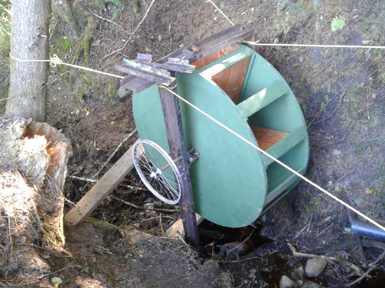 Water Wheel, resin & paint on wood and
plywood. (Ropes are temporary supports.)
Water Wheel, resin & paint on wood and
plywood. (Ropes are temporary supports.)
The converted permanent magnet 'car alternator' will be mounted up top
above
the bicycle wheel "pulley" and connected with a long flat/poly-V belt.
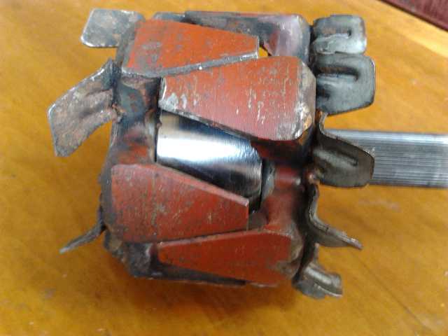 The coil in a car alternator was replaced with
a ring supermagnet, north at
The coil in a car alternator was replaced with
a ring supermagnet, north at
one end and south at the other, to make it a permanent magnet
alternator.
(The N and S 'petals' were twisted to equal gaps during assembly.) (TE
News #104)
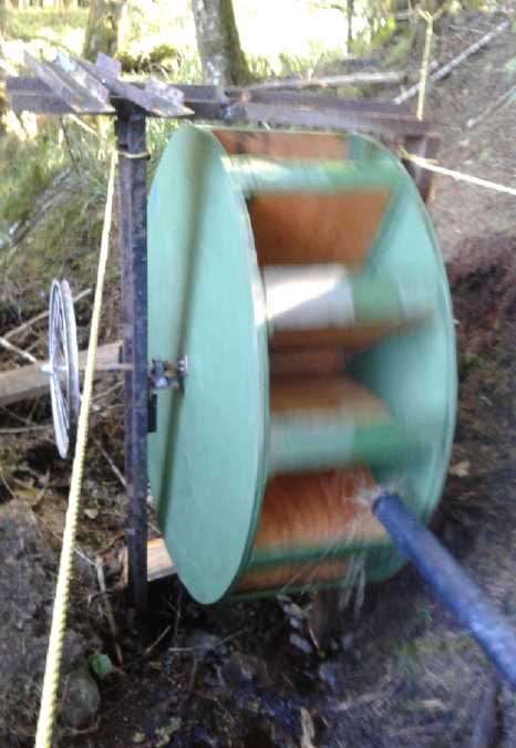 In 2016 I converted a small car
alternator to permanent magnet with a big ring supermagnet. It worked
okay, but I had found no particular use for it myself. Was I just going
to hang onto everything on spec? "You can't take it with you." I gave
it to him. Somewhat to my surprise, he built a big waterwheel out of
plywood and had it set up this month. Just a trickle of water was
flowing, but it turned. (Gosh, you mean I actually inspired someone to
do something?) It wasn't what I had (very vaguely) visualized and
didn't make full use of the available head, but it should work!
In 2016 I converted a small car
alternator to permanent magnet with a big ring supermagnet. It worked
okay, but I had found no particular use for it myself. Was I just going
to hang onto everything on spec? "You can't take it with you." I gave
it to him. Somewhat to my surprise, he built a big waterwheel out of
plywood and had it set up this month. Just a trickle of water was
flowing, but it turned. (Gosh, you mean I actually inspired someone to
do something?) It wasn't what I had (very vaguely) visualized and
didn't make full use of the available head, but it should work!
When I visited there was just enough water flowing to turn
it. The pipe will be replaced by a wide flume. I look forward to seeing
the generator connected and all running. (It'll have to rain first!)
Floating Tidal
Power Vessel
I printed out and took the
diagram and photo of the Scot Renewables floating tidal power vessel to
a cafe I often go to (Angela's Place in Port Clements, pop <300).
There was considerable interest over lunch. (...there's nothing like
hard copy, especially where there's no internet service!) Someone said
it would make no sense to put in tidal power when we could just keep on
burning over 1000 liters of diesel fuel a day. Seeing that's the only
figure I've heard, let's use it. Let's see... 1000 * 365 = 365000
liters per year (or more)? Gasoline here is around 1.75 $/L. I don't
know what BC Hydro pays for diesel - probably a good discount. Say just
for the sake of round numbers it was 1.3698 $/L, that would be 1/2 a
million dollars of oil per year. The next question is, how much would
it cost to build a unit to reduce that by say 70%, saving 350,000 $/yr?
I wish I had some figures for the usage besides "peak load
of 10 MW" -- is that for the north grid, or the whole island? And what
is the average load? I have a feeling that a 2 MW generator would save
the 75% of that diesel fuel, with much of the remainder of the oil
being used at slack tides. But without more figures I can't be sure.
Then there's the other factor: how big do we really want to go for a
first project? Scot Renewables would probably have the confidence to go
for the full size (unless they think the sound is too shallow). They
have experience. We might be better to go for half a megawatt, or even
200 or 100 KW.
For a while I thought here was a case where it would be
good to just be the second penguin into the water and copy what has
already been done. But Scot themselves are improving their design (and
certainly aren't ready to export). But I've thought of a couple of what
would hopefully be improvements.
Smaller Propeller in Venturi
From thinking about the potential much smaller Tlell River
project earlier, I think the safe way to go is to have intake "scoops"
with flat(ish) bottoms each feeding a venturi tube and outlet with much
smaller propellers at the focus where the water is going fastest. If
the water is too shallow the scoops will rest on the bottom instead of
big propellers hitting the hard gravel or rocks. (And, without trying
to forget the substantial cost of the extra housing) the propellers
will be smaller and cheaper. Plus, hearing concerns about fish and
seals in the sound - not to mention seaweed and crap - a cone shaped
grill can cover the front end so they won't be sucked through the
propeller.
How's the math? If the cross section at the propeller was
1/3 of what was taken in, would the power be the same as a propeller
with the same cross sectional area as the scoops? Let's say that area
was 10 square meters, so a meter length of that would be 10 Mg (10,000
Kg, 10 tonnes). Assume COP of .3 in both cases. Assume the water is
flowing at 2 meters/second. For the propeller:
Watts = COP * .5 * Mass * area * V^3
= .3 * .5 * 1000 Kg/m^3 * 10 sq.m * 2 m/s^3
= 1500 * 8
= 12,000 watts
For the scoop, the velocity must be triple where the cross section is
1/3 of the intake in order to lets the same water flow through:
= .3 * .5 * 1000 Kg/m^3 * 3.333 sq.m * 6 m/s^3 = 108,000 watts
What's wrong with my math? Somehow I don't think you can get 9 times as
much energy from the same water flowing past depending how you harvest
it. The narrower the venturi, the more energy by the square of the area
reduction? 16 times as much from a 1/4 size opening? That doesn't make
sense.
Perhaps the answer may be that as the size of the venturi
is reduced more water will make its way around the entire unit, and so
the velocity at the center won't be as high as the ratio of areas would
indicate? That doesn't make sense either.
Self Steering for Optimum Position in Stream
The other improvement would be the previously mentioned
automatic rudder system to steer the anchored vessel into the fastest
flowing part of the stream. And considering navigation in Masset
channel, one could also put in means to detect oncoming logs, vessels
and even log booms, and steer out of their way. Plus, if production
deteriorated, for example if the grills were clogging up with seaweed,
it could steer itself over to the edge of the channel (or take a manual
command to that effect) where it would be grounded at low tide in order
that it could easily be worked on - whatever needed to be done "in
drydock" during low tide. This would make for a huge savings in
maintenance costs. No need to send a boat or vessel out to it, it'll
come to shore. And of course it would aim itself between tides so that
the anchor rope and electrical cable wouldn't start twisting up with
repeated reversals of direction.
Sensors involved for these things would be:
* Left and right pressure sensors to detect if the flow is stronger on
one side than the other.
* Orientation sensor ('compass').
* Visual, sonar or other detector for oncoming obstacles.
* Radio receiver to recieve the "come to shore" (or other) command.
Also there's another opportunity. The channel is something
like 40 Km long, so it takes time for the water to flow in and out.
According to the UVic 2004 study, the tides in Masset Sound are 3 hours
later than those of the ocean outside the channel. On the 10th I
visited Masset. At what must have been high tide outside, water was
still pouring into Masset Sound. And it must be even later at the
inlets in the center of the island. The power lines also run the length
of the channel to the south side of this shallow inland sea. That give
us the potential of having two vessels, one near the mouth of the
channel, and the other near Masset inlet. The tides would never be
completely slack at both of them, so there would always be some power
being generated at one end of the grid or the other.
On this trip I also talked to someone from North Arm
Transportation who deliver barges of goods (like my shipping container
and electric vehicles) and petroleum fuel up and down the Canadian west
coast. He thought the Scot Renewables vessel had been built at Meridian
Marine, a vessel builder in Richmond BC -- or at least, that some tidal
power concern in Scotland had had theirs built there. This seemed
interesting. Perhaps there's more tidal power expertise in BC that can
be tapped than I knew about?
At the Swiilawiid Energy Symposium on the 29th and 30th, I
kept racking my brain for a good way to get community involvement in a
tidal power system. The Scottish tidal power vessels mentioned last
month looked better than anything previous and had a great track
record. It seemed to me to be more practical than anything else. Plus I
had further ideas - the computer controlled rudder and the venturi
power unit idea. The symposium brought forward the "SolShare" co-op
energy investment idea.
I decided I should go for a 100 KW unit if it can be co-op
financed. (See September in Brief about that idea.)
In the meantime make rather small test models of my plans,
and try them behind a powerboat. I could make components just large
enough to drive my new Piggott generator. Then, if circumstances
warranted trying to develop a "real" unit, I'd have some real world
data that said for example if the venturi tube idea really seemed
better than just a big propeller, and whether having multiple
propellers in-line in the venturi was better, worse or made no real
difference. And any other configuration that seemed worth testing.
The very first thing would be a propeller shaft and
housing that could have a belt or shaft running through a tube from
under the water up to the generator in a housing above it. Sort of like
a big reverse outboard motor. (Maybe I'll get to try out my various
long-held electric outboard ideas on this?!? ...Or maybe for the test
unit, just use an actual outboard motor shell? Hmm!)
Rechargeable
Battery Making
with oxalate electrolyte:
I didn't have time to look
at the lead-zinc cell. Or inclination for that matter.
MnO2-Zn Cell
From Scratch With Pocket Electrodes (continued from TE News #122)
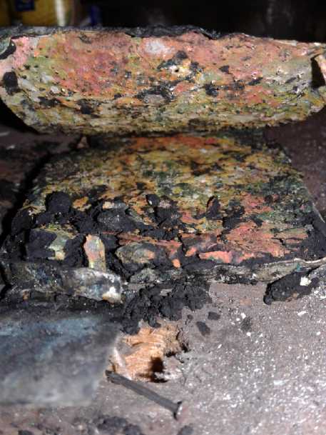 On the 13th I pulled the MnO2 electrode out and took it out to the
shop, and without disassembling it I punched a whole bunch more holes
in it. I must have about doubled the number. The metal curled up with
the punching and some small amount of substance came out to make a
mess. I got a picture of the confusingly colorful inside. Then I had to
put it in the press and "crimp" the edges more or less closed again.
On the 13th I pulled the MnO2 electrode out and took it out to the
shop, and without disassembling it I punched a whole bunch more holes
in it. I must have about doubled the number. The metal curled up with
the punching and some small amount of substance came out to make a
mess. I got a picture of the confusingly colorful inside. Then I had to
put it in the press and "crimp" the edges more or less closed again.
Sure enough, charging currents were around double what
they had been. They started at around 1/2 an amp and gradually sttled
in at about 110 mA. But it didn't seem to do anything to the short
circuit current - still well under an amp after a few seconds, and
later even 1/2 an amp. (Shouldn't it go UP as it charges?) So... did
more holes help, or not? Certainly not like I expected they would! I
began to suspect that the paucity of holes wasn't much of a factor. If
that was true it was good news since they were still so hard to make.
On the 13th and 14th I turned the charge off for the
night. In the morning the voltage had retained over 1.0 volts, then
over 1.1 volts. On the 15th I hoped it would hold to 1.2, but it seemed
semi-shorted. I opened it and it was okay again. I found that with the
various manipulations both electrodes were bent a little and they were
probably making contact with each other. The fact of the oxide on the
nickel-brass 'positrode' pocket probably prevented it from being a dead
short. (Somewhere I had some sheets of plastic square grids from
"Michael's Crafts" store, but I haven't located them since I moved.
They'd make better pocket electrode separators that would be hard to
short out.)
Later I repeatedly found bad aligator clip connections at
a
corroding electrode giving low voltage readings: there probably was no
short.
Oxides (& oxalates?) on the shell may also explain why
the currents were low and dropping. If the electrode case was only
connecting to the substance through oxide, the conductivity could be
pretty low. The next thing to do would be to make another electrode and
paint the osmium doped film on it. Unfortunately, I had other things to
do.
I did however continue to charge it at 1.72 volts drawing
about 100 mA steady, and its performance continued to gradually
improve. After a couple more days it held over 1.500 V for a minute,
then nearly 2 minutes the next day, and would put out over 4 amps
momentarily. By 10 seconds it was hardly over an amp, but that was
still a substantial improvement. On the 19th it held above 1.5 V for 3
minutes, and shorted would put out over 4 A immediate and still over 2
A after 10 seconds, which further indicated it wasn't simply a shortage
of holes causing the low currents.
On the 20th charging current was down to 90 mA at 1.725 V,
and taken off, it held 1.500 V for over 4 minutes. Apparently the 25
amp-hours of MnO2 was still gradually charging. That night I
did a short
load test with 5 ohms. It started at 1.35 volts and dropped gradually
to 1.0 volts over 5.0 minutes. At least it was something.
Sanded electrode next to
unsanded zinc sheet
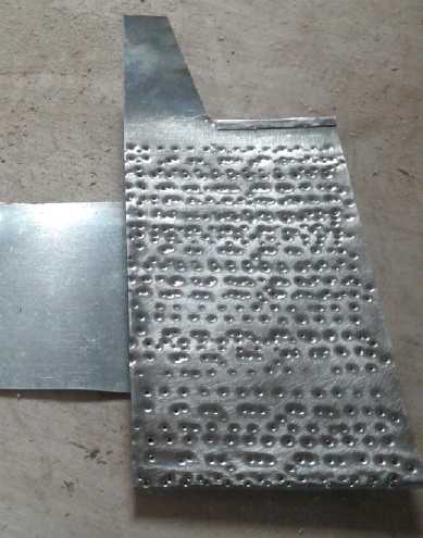 On the 18th I
made a new zinc electrode. That's the easy
one to do. Just a 10" long piece of zinc strip plus a connection tab. I
punched it full of holes and folded it over so it was a two-layer 5"
electrode. But I didn't get it put in. On the 20th I thought of another
way to increase the surface area: sand it. It was too late for the
inside with all the ragged perforation edges, but I hadn't etched it
yet. I sanded the outside with #240 grit
sandpaper.
On the 18th I
made a new zinc electrode. That's the easy
one to do. Just a 10" long piece of zinc strip plus a connection tab. I
punched it full of holes and folded it over so it was a two-layer 5"
electrode. But I didn't get it put in. On the 20th I thought of another
way to increase the surface area: sand it. It was too late for the
inside with all the ragged perforation edges, but I hadn't etched it
yet. I sanded the outside with #240 grit
sandpaper.
Later I had no time to work on it. It had self discharge
that got worse. Toward the end of the month I drained the electrolyte
and it had a blue tint to it. My thought was that it looked like nickel
or copper chloride. The metal would have come from the positive current
collector, but there was no chloride in my cells. After all that's why
I used oxalate! Where on earth could chloride or something else that
would dissolve nickel or copper have come from? I wasn't until October
3rd I remembered: I etch the zinc in ferric chloride! Then I scrub it
off, but there's no guarantee that I get all the chloride off by
scrubbing it. It certainly doesn't look like bright zinc after. Perhaps
I should soak the zinc electrodes in water for a while after etching
them, or maybe it needs some other treatment (soak in solvent?) to be
sure there's nothing there but zinc?
Could something to do with the ferric chloride be causing
the self discharge? The things you don't think of can really throw you
off!
I didn't get back to it in September, with the last week
being prep for the Energy Symposium.
To Make Sodium Oxalate
I was thinking some Na2C2O4 might help speed up the
electrolyte reactions. But I wasn't planning on ordering any chemicals.
On the 5th I realized I didn't need to. I had a bit of oxalic acid
left. Mix that with sodium hydroxide and you get sodium oxalate and
water. (Duh!)
http://www.TurquoiseEnergy.com
Haida Gwaii, BC Canada