Turquoise Energy Ltd. News #125
covering
October
2018 (Posted November 3rd)
Lawnhill BC Canada
by Craig Carmichael
www.TurquoiseEnergy.com
= www.ElectricCaik.com
= www.ElectricHubcap.com
= www.ElectricWeel.com
Month
In Brief
(Project Summaries etc.)
- Solar Rewiring - HE Ray Energy - Bandmill Improvements &
More Milling - VAWT
In
Passing
(Miscellaneous topics, editorial comments & opinionated rants)
- Putting up the Beveled Siding - Home Milk Pasteurizing -
Treating
Foot Corns - The Moral Dilemma of Uninvited Migrants - Be Prepared for
Economic Trouble - A Minor Service Sector?: the Average
Financial Salary in New York 431,000 $US - Orange and Red Peppers from
the Greenhouse & Indoors - Metric System Length
Problem: the real reason English/Imperial measures are better - Black
Flamingo Event
- Project Reports
-
Electric
Transport - Electric Hubcap Motor Systems
* Electricity is cheaper than gas - but it does go on your home power
bill (duh!)
Other "Green"
Electric Equipment Projects
* Carmichael Mill ("Handheld Bandsaw Alaska Mill") - Band
Sharpener - New Bands, Cutting & More & More Cutting -
UHMW Main Wheels & more cutting - Production Model Design?: As is!
- Sell the special components as Kits!
Electricity Generation
* How Not to Build a Vertical Axis Wind Turbine (VAWT) - Initial
Theories - Construction and Testing
* Solar Panel Rewiring
* Tidal Flow Power Unit: Cheaper, Better! - Cheap Floating Power
Vessel Hulls? - Ducted Fans and Venturies
* Short Space Ray Energy: a new design?
Electricity Storage -
Turquoise Battery
Project (Now Mn-Zn, Ni-Zn or Pb-Zn)
* Another idea for a Conductive Graphite Material?: Conductive
Polyurethane Paint
I must have been a bit burned out after the Energy
Symposium on September 29th and 30th. With no other special task to do
it took me 6 days to get out the last newsletter and then turn to some
other writing I'd been neglecting for a couple of weeks.
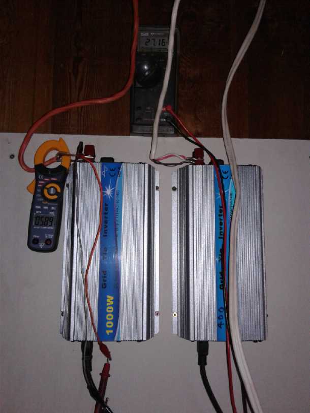 But I did
rewire the rooftop solar panels on the third and fourth. I split them
into two pairs for 500+500 watts, each with their own wire and (for
now) their own grid tie inverter. With two inverters I finally got over
400 watts output - but not much over 500, and with lengthening winter
shadows, that much only for a couple of hours in the afternoon. And
only if it was sunny. There were some power failures in high winds
toward the end of the month, and very little power output in clouds and
rain. Reliable tho they were proving to be, I turned off and unplugged
the inverters to avoid any problems or failures in potential "brownout"
or power line voltage spike conditions.
But I did
rewire the rooftop solar panels on the third and fourth. I split them
into two pairs for 500+500 watts, each with their own wire and (for
now) their own grid tie inverter. With two inverters I finally got over
400 watts output - but not much over 500, and with lengthening winter
shadows, that much only for a couple of hours in the afternoon. And
only if it was sunny. There were some power failures in high winds
toward the end of the month, and very little power output in clouds and
rain. Reliable tho they were proving to be, I turned off and unplugged
the inverters to avoid any problems or failures in potential "brownout"
or power line voltage spike conditions.
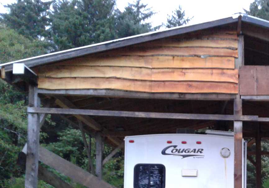
On the 6th I made use of
the beveled alder siding I cut a month previously. (Pictures, see "In
Passing".)
I talked with
someone about HE ray energy, which inspired me to look up some circuits
again, printed and on youtube. I
saw an interesting magnet demo, and found radiant energy devices that
seemed to use that effect.
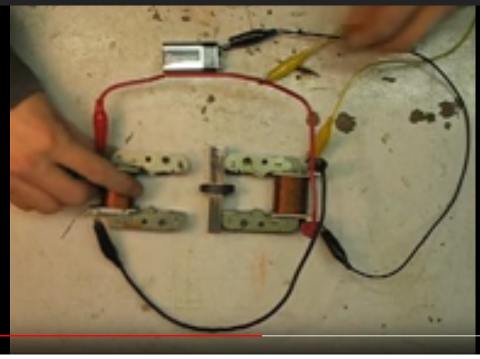 Magnet Switching Demo
Whichever "U" of iron is brought next to the center "bar"
permanent magnet first, "sticks" to it.
The second one then won't stick, unless the first one is pulled away.
Then there was an electrical demo:
If momentarily pulsed one way, one "U" electromagnet (permanently)
"sticks" to the center
"bar magnet". If pulsed with the other polarity, the other "U" sticks
and the first one lets go.
Never do both "U" bars stick to the magnet as one might suppose they
would.
One device seemed to have some similarities to the
toroidal one I had been working on, plus it had features reminiscent of
the magnet demo. Presumably when power was applied to the left hand
coil, an electromagnetic circuit flowed around the left side of the
unit through the permanent magnet. Then when it was turned off, the
flow would "switch" to go through the right hand coil. As previously
noted it appears that HE rays discharge their energy as they pass
through a suddenly switched electromagnetic field, and into that field,
making it stronger than the original impulse. And this seemed to be a
good way to get suddenly switching fields. It would probably be a
momentary field, on and then off again because (all else being equal)
the gap would favor the field staying on the left side.
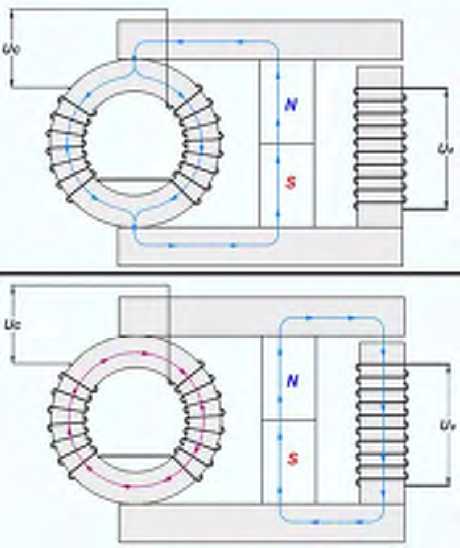
I cobbled something together, but I got no output at all.
Perhaps this type needs different pulses: much lower frequency because
of having an iron core, and pulses powerful enough to saturate that
core. I didn't get into designing a circuit to do that. I also put the
gap on the toroid side. (shouldn't that work just as well?)
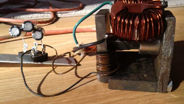 Sort of a "stood on end" version of the above
in regular steel.
Sort of a "stood on end" version of the above
in regular steel.
 I wanted to
get back to milling lumber with my handheld
bandmill, but a want of sharp bands and reluctance to tackle conversion
of the band sharpener to suit my bands kept me from it until the 13th
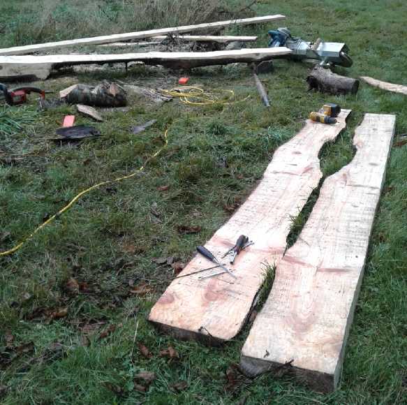
when my order for 5 new ones arrived. Following that I started cutting
more of the spruce and finally cleared up one of the dozen areas
cluttered with spruce logs and cants. Finally! Then I tackled the
next area and finished it up. At the same time I made a
UHMW- polyethylene main wheel for the undriven wheel. It worked well
and
the slippery UHMW didn't get a buildup of sawdust on it like the
plywood wheels. Then I made another one for the drive wheel. I was
afraid it would slip, but provided there was sufficient band tension it
worked. The UHMW wheels solved the problem of sawdust buildup that
caused the band to mistrack forward, which would get the teeth trying
to cut metal in the saw and dull them. The bands started lasting much
longer without having to keep a watchful eye on the wheels and keep
scraping the sawdust layers off them.
I wanted to
get back to milling lumber with my handheld
bandmill, but a want of sharp bands and reluctance to tackle conversion
of the band sharpener to suit my bands kept me from it until the 13th
when my order for 5 new ones arrived. Following that I started cutting
more of the spruce and finally cleared up one of the dozen areas
cluttered with spruce logs and cants. Finally! Then I tackled the
next area and finished it up. At the same time I made a
UHMW- polyethylene main wheel for the undriven wheel. It worked well
and
the slippery UHMW didn't get a buildup of sawdust on it like the
plywood wheels. Then I made another one for the drive wheel. I was
afraid it would slip, but provided there was sufficient band tension it
worked. The UHMW wheels solved the problem of sawdust buildup that
caused the band to mistrack forward, which would get the teeth trying
to cut metal in the saw and dull them. The bands started lasting much
longer without having to keep a watchful eye on the wheels and keep
scraping the sawdust layers off them.
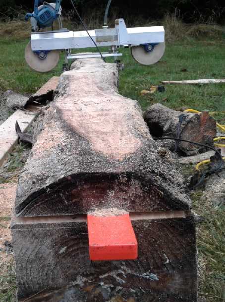
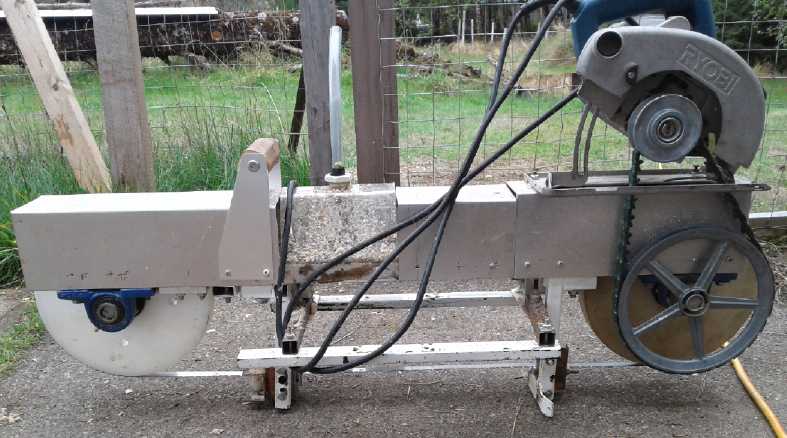
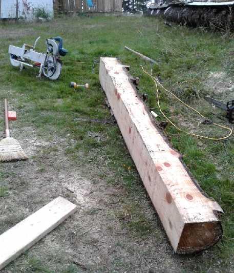 In fact, the whole mill was now performing quite well
and without having to keep adjusting anything or watch out for anything
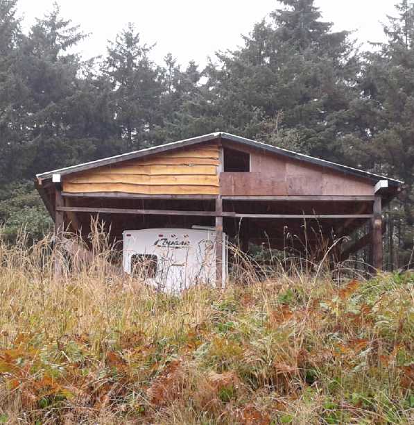
special other than the band cooling water tube running dry. I cut a
couple of sections (10'+10') from the small end of the so far uncut big
log by month's end. (The butt end is seen 'far away' at upper right
with some metal roofing pieces on it (plastic draped down at the
roofing joins). Someday I'll get to it!)
In fact, the whole mill was now performing quite well
and without having to keep adjusting anything or watch out for anything
special other than the band cooling water tube running dry. I cut a
couple of sections (10'+10') from the small end of the so far uncut big
log by month's end. (The butt end is seen 'far away' at upper right
with some metal roofing pieces on it (plastic draped down at the
roofing joins). Someday I'll get to it!)
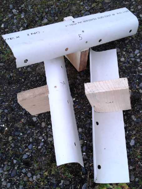
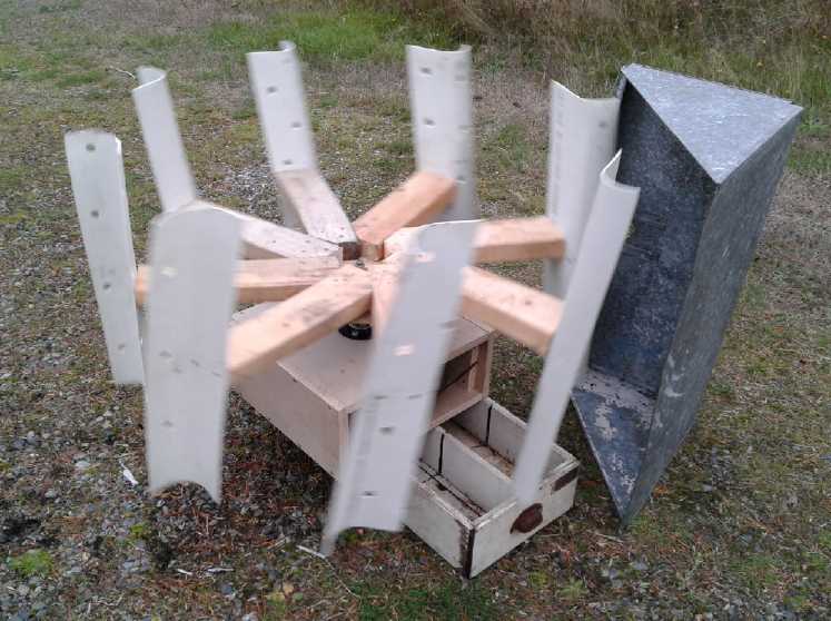
 On the 23rd it
was raining in the morning and I decided to
try making the vertical wind turbine (VAWT) with the rotor blades made
from scrap PVC pipe so long ago. In a day I had it done, and I mounted
it on top of the Improved Piggott Alternator I made in September. But
it didn't perform well. I tried various angles of attack for the
blades, but in the howling gale, it never got turning faster than LP
phonograph speed, about 33-1/3 RPM. I looked at the one on youtube I
was trying to copy in 2013. I had the vanes inside out, so I turned
them around. It didn't help. I'm sure there are better designs.
On the 23rd it
was raining in the morning and I decided to
try making the vertical wind turbine (VAWT) with the rotor blades made
from scrap PVC pipe so long ago. In a day I had it done, and I mounted
it on top of the Improved Piggott Alternator I made in September. But
it didn't perform well. I tried various angles of attack for the
blades, but in the howling gale, it never got turning faster than LP
phonograph speed, about 33-1/3 RPM. I looked at the one on youtube I
was trying to copy in 2013. I had the vanes inside out, so I turned
them around. It didn't help. I'm sure there are better designs.
But two things made real difference to performance: (a)
putting a wind block in front of the side moving into the wind, and (b)
finding a better location. My driveway seemed to be something of a
"wind funnel" and a steady breeze blew up it from the ocean. The unit
hit 90 or 100 RPM, but it didn't make much power. To get much voltage
at that speed the generator would have to have far more turns of far
finer wire.
Definitely even with a vertical axis turbine if you don't
have a good location you've got nothing. I may buy a new cheap Chinese
anemometer with a detachable sensor for remote reading (having lost or
misplaced the old one - grr!) and stick it on the end of a long pole to
try out some different spots.
In Passing
(Miscellaneous topics, editorial comments & opinionated rants)
Putting up the Beveled Siding
If cutting lumber with the new handheld bandmill is
straying a little far from being a "green energy" project, using that
lumber is even farther off. But on October 6th I used the alder "one
live edge" beveled
siding I cut on September 3rd (now "well seasoned" - hah!) on the
windward gable end of the roof over my travel trailer. Why I picked the
first rainy day in a while to do outside construction work on ladders
I'm not sure. except that the internet wasn't working and I was unable
to post TE News #124 until evening.
Like I said last
month, if I'd had this planned I'd have cut the log section a little
over 12 feet long so the boards would go from one side to the middle of
the building. (25 feet, across the entire face, might be even better!)
As it was, I cut them shorter and had a seam in the middle except for
the top few where it narrowed toward the peak. I used all but one, 8 I
think it was. There were a lot of waste scraps. I cut the first one a
bit too short. So I unscrewed it, but soon had to use it anyway. If -
when - I make more, I can change it. (I put in the screws a little
lower so they aren't under the board above.)
I decided I'll cut down
a few more alder trees to make
similar siding for the rest. At least for a wall or two. Some of the
scraps might fit beside windows.
I'm wondering if there's some way to seal around the edges
besides putting up plywood or wallboard of some sort under the siding.
(Ty-Vec?)
Home Milk
Pasteurizing
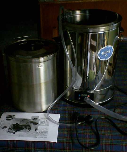 The countertop
milk pasteurizer I ordered from Czech in August arrived in
September. On October 7th I got 3-1/2 quarts of raw goat milk from down
the road to try it out. It seemed to work well. I poured in the milk
and ran "hot" water in from the tap through the hose until it was
coming out the top tube. I plugged it in and pressed "heat". It heated
the water in the outer jacket up to 84°C and then maintained that
temperature. (It was adjustable, but that default seemed like a good
setting.) I stuck in the thermometer a couple of times - and used it to
stir the milk - until the milk soon hit 80°, and then I shut it
off. Then I connected the cold water tap and started running cold water
through the jacket. After a while the water coming out, very hot at
first, was down to 12° and the milk continued to cool. When it was
down to about 15° I used a funnel to pour it into a 4 liter jug.
The countertop
milk pasteurizer I ordered from Czech in August arrived in
September. On October 7th I got 3-1/2 quarts of raw goat milk from down
the road to try it out. It seemed to work well. I poured in the milk
and ran "hot" water in from the tap through the hose until it was
coming out the top tube. I plugged it in and pressed "heat". It heated
the water in the outer jacket up to 84°C and then maintained that
temperature. (It was adjustable, but that default seemed like a good
setting.) I stuck in the thermometer a couple of times - and used it to
stir the milk - until the milk soon hit 80°, and then I shut it
off. Then I connected the cold water tap and started running cold water
through the jacket. After a while the water coming out, very hot at
first, was down to 12° and the milk continued to cool. When it was
down to about 15° I used a funnel to pour it into a 4 liter jug.
Basically I did for a few liters what Island Farms Dairy
Products does for millions of liters using millions
of dollars of equipment. Maybe not quite as exactly, and probably
it cooled more slowly, but close enough. Of course, you can always just
heat
milk just
until it starts steaming in a pot on the stove, too. (A thermometer
would be the biggest plus for that.) But I'm sure the pasteurizer gives
more
consistent results, and without overheating the milk at the bottom.
Then, being susceptible to migraines from any but the
freshest milk, and using up milk pretty slowly myself (mostly with
cereal), I did what I
usually do with milk: I poured it into little plastic drink bottles of
around a cup each (17 of), screwed on the lids, and put most of it in
the freezer
for future use. Frozen, it stays good for ages.
When I want some I get out a container and put it in a tub
of hot water to thaw out, which is under 10 to 20 minutes depending
partly on whether you shake the bottle occasionally. (I don't use the
microwave because the containers warp and shrink.)
Treating Foot
Corns
As I was preparing to move from Victoria to Haida Gwaii a
couple of years ago, I noticed an irritation in the outer ball of my
right foot. I had been wearing the same sandals for some time. I
thought maybe a sliver of metal from the shop had got in there. I
looked at the sandal and saw nothing. But it seemd to persist and I
looked again. This time I saw a sliver of metal sticking up. Aha, that
must explain it! I took it out. But my left foot now seemed to be
having the same feel, like something was stabbing it. There was nothing
there. This feeling in both feet continued.
After I had moved I had stopped wearing those sandals, but
my left foot had a bump there. It was a corn. I had never had such a
thing before. And I could feel but not see something there on my right
foot too. Those sandals had on the top of the sole a square "grille"
pattern of plastic sticking up. There was a pretty thick pad on top
of that, but obviously as the sandals became more worn, it wasn't
enough. Where my feet pressed most heavily they were stressed over an
edge of one of the ridges. This appeared to be the cause. There were
two spots, a large inner corn and 1/4" away farther toward the edge of
the foot, a small outer skin
disturbance.
I looked in Wikipedia to see more about corns, but it
didn't explain what they were or the root cause(s). It didn't seem like
there was anything foreign there, like the virus(es)(?) associated with
warts. I had occasionally had ingrown hairs. The corn, I figured, was
like "ingrown skin", where confused convolutions caused by uneven
pressure made the dead skin
layer go inside instead of being on the surface. So it didn't seem
right to try "killing" something with freezing or wart remover. The
skin had to be turned the right way out again. If this hyposthesis was
right, it meant that the corn would probably spread out and become
seemingly worse before it could get better.
I adopted a three-pronged approach. I'm sure all three
parts were important. Since they were on the bottom of my feet and were
being aggravated just by walking, the first and most obvious one was
to wear thick socks and the most padded shoes I could find.
The second part was to shave off the thick, dead outer
layer of skin, the lump that stuck out. This both reduced the pressure
on the
corn when I was walking and thinned out its outer "shell" to make the
third treatment more effective. I used an ordinary disposable shaving
razor. At no time was there any pain, sign of blood or any other
indication that I had cut into living tissue or irritated anything. I'm
sure that would have been quite counterproductive.
The third part was a "folk treatment": Paprika, carried in
butter to make a "paprika cream". This I rubbed on the corns. Ideally I
think it should have been a couple of times a day if not more, but I
usually only did it once, and as they got better, less and less.
Finally as they pretty much ceased to irritate my feet, many days would
go by when I wouldn't think about them at all. This surely much delayed
their final disappearance, because they didn't improve except with the
treatments, even when they had become pretty insignificant. Finally,
after all this time, perhaps two years, I'd rate the left one as being
'gone', or at least virtually undetectable, and the right one isn't far
behind. I decided I wouldn't write about this treatment until (and
unless) I could declare it successful. They were almost done many
months ago, but I only finally got some more paprika and butter and
started going at them again and polished them off in the last few
weeks. I've been keeping it in a shallow plastic tray, which has saved
the
little cat food tin of paprika from being spilled on the floor more
than once.
My theory about them getting worse on the surface first -
as they actually started improving inside - seemed to be borne out. The
first thing that happened after I started treating was that the
heretofore invisible sore spot on my right foot now erupted into a
mirrored carbon copy of the corn on the left foot. I had hoped that
wouldn't happen, but apparently the damage was already there inside.
Then the small outer blemishes became corns too, both feet
now about the same. Then the space in between the large inner and small
outer corns filled in and they became single elongated corns over 1/4"
long. Doubtless this was along the edge of where the ridge in the
sandals had been. And there were days when they must have grown worse
because of overmuch aggravation from walking and working while on my
feet,
but in general they very gradually shrank with treatment - when they
got treatment. They probably could have stood to be treated 3 or 4
times a day, and would doubtless have been gone far sooner. But for
that one would have to interrupt one's day, take the shoes and socks
off, and go off to get the paprika paste and razor. I probably did that
occasionally when they were at their worst and most irritating. I don't
really remember now. But mostly it was once or twice a day, then less
as they improved.
The Moral
Dilemma of Uninvited Migrants
There are already more refugees on the move or living in
temporary camps than at any previous time in human history. Yet what we
have witnessed so far is only the beginnings of vast migrations even of
whole peoples. Economic conditions are becoming desperate in many
lands. War has played its part, especially in the destruction of Middle
Eastern countries and North Africa. Whites are fleeing persecution in
South Africa. The Sahel continues to dry out and the Sahara Desert to
expand, so people are fleeing that region. Europe has been bearing the
brunt of this so far, with Italy and Greece becoming overrun with
migrants mostly from Africa. ("Palermo is no longer an Italian city."
said its mayor in early 2017.) Australia has been working for some time
to quietly repulse shiploads of southeast Asian migrants. So far lesser
troubles have started to be felt in North America.
But populations in many lands without ready access to
birth control products are starting to exceed levels that can be borne,
much less supported with a good quality of life. Notwithstanding
doubtless politically motivated factors in the present "caravan" mass
marches and bus rides en route from Honduras to USA, this is probably
what we are just beginning to see in migrations to North America from
Central, and maybe soon South, America.
And soon, as sea levels rise due to global warming, and as
storms and storm surges get worse with rising sea water temperatures,
there will be more migrants moving from flooding coastal lowland
regions to
higher ground. Sea level rise has been measured to be accelerating
exponentially in recent years. Oceans may be up a meter by mid century,
with storm surges inundating as high as 50 feet. Enormous numbers of
people living at low elevations will be flooded out. In Bangladesh
where there are elevations of only ten feet even 100 miles inland, we
are likely to see one hundred million people looking for new homes.
Other
changing conditions will doubtless uproot more people. (Hmm... My house
is on a little "hilltop" about 50 feet up from the high tide mark. How
fortunate it may soon
be that I didn't get one of the low lying ones I originally wanted to
buy!)
Naturally many coming from desperate circumstances will
want to reach the various fabled lands of freedom and democracy to find
greater opportunity - or even opportunity to preserve their life. Huge
influxes of refugees of other languages, other cultures and generally
with less or even little education would impose an enormous tax and
social burden on the citizens of destination countries. Australia could
be easily overwhelmed by more incoming migrants than it has present day
citizens. With "open doors" policies European and North American
societies and culture could potentially go down the drain too. The
future quality of life in these lands will to a great extent be
determined by the quality of the peoples that are permitted to enter -
and mass economic migrants may be by and large those who weren't
"making it" in their own lands. White people, having created birth
control products, are quickly becoming a
minority everywhere. IMHO it would be better to have some lands
remaining and progressing as an inspiration and a model to the rest or
the world than for it to all become homogeneously "slower to progress"
nations. I think that would tremendously retard planetary progress
toward Social
Sustainability and the Days of Light and Life.
This book goes into details:
Answering the Moral and Ethical Confusion of Uninvited Migrants
https://sites.google.com/view/danielraphael/free-downloads
Boiled down to essentials, one can and certainly should be
sympathetic toward neighbors in difficulty, but that doesn't mean
you're obligated to invite them to come and live in your own house. Or
especially to take them in uninvited!
Be Prepared
for
Economic Trouble
Okay, I've been saying there's a collapse coming for some
years now. Some might say nothing has happened, but in some countries a
collapse has happened or is in
progress; in others, the signs of
serious trouble are there beneath the surface, such as nearly 1/2 of US
households having trouble simply making ends meet and having unpayable
mortgages, student
loan debt, credit card debt and no savings.
I'm led to repeat the warnings which are coming now from
every
direction (except perhaps the so-called "mainstream media"). A 50-70%
drop in
stocks will hurt retirement funds, which are heavily invested in such
risky assets seeking to get enough yield to remain solvent. A "perfect
storm
financial crash" (as one analyst puts it) seems inevitable as the
"Everything Bubble" starts to pop. The US
federal reserve is quickly drying up global liquidity in our "Ponzi
scheme"
financial system. The causes are obvious, and the cures are not
unknown, but it would seem there's no leadership anywhere willing to
tackle the
problem. It is unlikely to end in complete dystopia, but we are heading
into a time when no assets are
entirely safe. Real wealth doesn't disappear, but tremendous transfers
of wealth are sure to take place.
On top of that are the ever increasing climate
catastrophes. Annual crop losses are reaching levels of "severe". If
you were on the coast in the affected areas of the
Carolinas, Florida or Texas, where are you now? Is your home still
there? Were your preparations suitable and effective? Will the next
hurricane be even bigger? Or, has your area lost crops in prolonged
droughts with
occasional severe flash flooding? hailstones that are killing crops and
even
sheep? forest fires? volcanoes or earthquakes or tsunamis?
No preparations are suitable for everyone. Personal and
environmental circumstances differ widely. Repeating myself perhaps ad
nauseum but in line with many others, in general have some
real assets - loss of trust in currency can erode its value rather
suddenly. Food stores and silver bullion come
highly recommended. If you're thinking you might retreat to a safer
place if things get rough, do you know where, and do you always have
whatever you need to get there? (eg, enough gasoline.)
And anything else you're likely to need over a few rough years as
applicable. Diversify your portfolio: Paypal and other non-bank
financial institutions may be better places to deposit some currency
than
banks in a banking collapse or bank "bail ins". Have some cash so you
can still buy things if there are "bank holidays".
A Minor
Service Sector?: the Average Financial Salary in New York is
431,000
$US
The financial services sector should be a very small part
of the economy. Ideally they hold and prudently lend other peoples'
deposited money as
capital for those who wish to do worthy real things but can't afford
the whole
price up front. For that they charge a small fee; interest.
Instead, under "10% fractional reserve banking", for every
1 $
on deposit the banks can essentially lend out 9 $ that doesn't exist.
Then when
those who receive the
borrowed money put that same 9 $ into their own bank accounts, the
banks can
lend out another 81 $ based in those deposits - rehypothecation of
money. Thus it is seen they are essentially
'printing money' out of thin air, all created as loans with interest
owing.
Therefore inflation - slow robbery of savings - and more
loaning, ever expanding indebtedness, must continue, otherwise there is
"deflationary debt collapse",
since there is nothing like the amount of actual money in existence to
pay
off debt as there is debt.
If your original dollar gets paid back to the bank as
interest on all that debt, or even if you simply take your dollar out
and put it under your mattress (BTW that really is where thieves look
first, then your dresser drawer, etc - your most personal spaces), the
base enabler for all that other money vanishes. With the original
dollar gone, there's just the 90$ created as debts.
That's where lack of "liquidity" created by the US Federal
Reserve - globally since the US dollar is the world's "reserve
currency" - by un-loaning even a relatively small amount of cash to
"shrink its balance sheet" makes it hard for those with debt to make
their payments.
The "fractional reserve" process has allowed the financial
services sector to grow
far larger than the total actual economy - the 90$ from the original
1$. Society has apparently no control over this cancer; the banksters
take what they please. Here are levels of
salaries and bonuses that make history's biggest and
most famous heists and robberies look like pocket change. The average
financial services executive in New York receives the amount shown in
the title
annually, and it is a far larger average than the compensation to those
who produce real goods or provide real services that contribute to the
economy
instead of sucking it dry.
(And all this while the banks they run are essentially
broke!
"Help, bail us out!" Is this fair and equitable to all?)
Orange and Red
Peppers from the Greenhouse & Indoors

 I grew some peppers (mostly purchased
seedlings) in the greenhouse; some in the ground,
I grew some peppers (mostly purchased
seedlings) in the greenhouse; some in the ground,
some in pots. I've never grown anything but "green peppers" before,
because they never
ripen before colder weather sets in. This year I brought the pots into
the house in
late September. In mid October, almost in a day it seemed, the peppers
on one plant
all turned orange. I put the other one under the "Indoor LED Garden"
lights.
Late in the month, they turned red. On the 31st I cut the rest and
dumped the pots out.
(The last green one turned red sitting on the counter in the first days
of November.)
I also got a couple more good green peppers from a plant in the
greenhouse.
Metric System
Length Problem: the real reason English Imperial measures are better
yard / meter - 1 syllable
/ 2 syllables
inch / centimeter - 1 syllable / 4 syllables
mile / kilometer - 2 syllables / 4 syllables
foot / 30 centimeters - 1 syllable / 6 syllables
cup / 250 milliliters / (quarter liter) - 1 syllable / 9 or 10
syllables
/ (4 syllables)
quart / liter - 1 syllable / 2 syllables
gallon / 4 liters - 2 syllables / 3 syllables
pound / kilogram - 1 syllable / 3 syllables
---
(Give them an inch and they'll take a centimeter?)
---
"There you go, 10 liters."
"Okay. Is that French liters or US liters?"
Black
Flamingo Event
[No One Expects the Spanish Inquisition!
- Monte Python's Flying Circus; episode, ~1975]
We know that the financial system is so complex and
fragile that we can expect some "black swan" event sometime will throw
everything for a loop globally. (Can one expect a "black swan"
event?) Maybe: a 50-70% stock market crash is presently being forecast
by many financial experts (and before month's end seemed to be well
underway).
What no one could ever have expected was a "black
flamingo" event (2013?). The black flamingo was first seen in Israel,
doubtless colluding with the ever-plotting Israeli
government. Next it was seen in Cypress, and then the banking system of
Cypress collapsed. Just three years after Cypress joined the EU, it
apparently went from stability into financial crisis. Under the demands
of the European Central Bank, the Cypress banks "bailed
in" to bail themselves out. They took a great share of peoples' life
savings on deposit and then prevented them from withdrawing their
remaining money, all so trustingly deposited. That worked so well that
every 'western' nation now has similar legislation allowing potential
confiscation of funds on deposit at major banks. (How that fits with
"deposit insurance" I don't know.)
It isn't clear from its little known public activity
whether the
black flamingo played a role in the banking plot, or whether perhaps it
was the one who warned all the Russian account holders (only the
Russians) a day or more in advance to withdraw their money from their
Cypress bank
accounts while they still could. The flamingo mostly stayed out in the
water trying to mingle with the other flamingos (doubtless to avoid
reporters with questions). Some might insist it was all just
coincidence. (Hey, I'm not making all this up. Just check out "black
flamingo" on Youtube. [The other facts and events are of record
too.])
The Scottish Miser's Guide to Economy
*
You can wear your socks and underwear twice as long between washings if
you
turn them inside out after the first week.
(Well it's probably pointless to try and think up any more after
that one!)
---
More and more frugality (Victoria BC): "End of the Roll" discount
carpets
couldn't afford to keep their whole store open so they shrank it and
let one end of the building go. It became the bargain store "Excess
Cargo" where one could buy small appliances, some great "off brand"
electronics and various things at amazing prices. This store was very
popular. I bought many things there, but the whole chain went under.
One of the employees turned the store into "McFrugals" with a somewhat
different line of even lower cost products. In spite of its success (or
at least, payment of the rent) the owner of the building decided having
such a "low class" paying tenant wasn't good enough and he evicted them
to renovate so
he could charge more money in this backwater area. I've moved, but I
wouldn't be surprised if it's now yet another vacant storefront with
"for sale or rent" signs out front, of which there were no shortage
when I left.
The "retail apocalypse" proceedeth apace!
---
I can't quite place it, but there must be something ironic about this
road sign:
"No Overnight Camping on Skidegate Indian Reserve"
"in depth reports" for
each project are below. I hope they may be useful to anyone who wants
to get into a similar project, to glean ideas for how something
might be done, as well as things that might have been tried or thought
of... and even of how not to do something - why it didn't
work or proved impractical. Sometimes they set out inventive thoughts
almost as they occur - and are the actual organization and elaboration
in writing of those thoughts. They are thus partly a diary and are not
extensively proof-read for literary perfection and consistency before
publication. I hope they add to the body of wisdom for other
researchers and developers to help them find more productive paths and
avoid potential pitfalls.
Electric
Transport
Electric Charges: It's the EV!
My power bill for July and August was about 150 $. That
was 75 $/month. It seemed rather high for summer. I'd have expected
more like 35 to 50 per month. Then I remembered the extra 25-40 $/month
was
for charging the Nissan Leaf after driving it. If that had been
gasoline it would have been more like (just guessing) 150-250 $. Really
it wouldn't have been quite so much because I would have driven less. I
would have skipped many trips which weren't absolutely necessary, like
weekly lunch in Port Clements, and I'd have put off trips to town
until the need became pressing in order to combine more things into
fewer trips. With electricity the fuel bill is nothing much to worry
about - about 2 ¢/Km - even if I can't pin down what the exact
total is. (I suppose I could write down odometer readings.)
Almost everywhere I drive is a 50 Km or more round trip.
If I was still living in Victoria where everything is close by, the
addition to the bill would have been almost insignificant.
Other "Green"
Electric Equipment Projects
Carmichael
Mill ("Bandsaw Alaska Mill")
After hitting two nails in
early September there was no more cutting until I had at least one
sharp band again.
Automatic Band Sharpener
This arrived near the end of September, but it was made
for wider bands with around 1" tooth spacing. In order to make it work
for 3/4" bands with 1/3" tooth spacing, I need to make a couple of
modifications. The first one was simple enough: I found some washers
the right size to put on the two bolts that held the band at the right
height.
Next, an offset cam moved the band too far and too fast
for the movement up and down of the grinding wheel, and also at the
wrong time. It would skip three teeth instead of one and the wheel
descended while it was moving instead of when it was stopped. I had to
drill a hole in a new rotation and closer the the center of a rotating
plate for the new offset cam that moved the band to the next tooth
while the wheel sharpened as it went. This mod made me nervous. I could
see about where it should go, but there wasn't much room, and if I was
off, the right place would overlap the one I drilled.
New Bands, Cutting & More & More Cutting
My order of 5 new bands arrived on October 13th. (.025" x
3/4" x 93", 3 TPI "meat cutting" stainless steel bands.) By the time I
was ready it was getting late. Nevertheless I put a new band on and
went out to cut. In about 20 seconds I was 4 feet though cutting a 2" x
6". It looked like I'd be done the 10 foot length in less than a
minute, but things started going funny about 2 feet from the far end.
On close inspection in the dimming light it appeared I had already cut
into this piece from the other end (over a month ago), and the two cuts
were meeting. So the board was nearly cut all along and was lying on
the band and jamming it. I put in a couple of wedges and finished
whatever bit was still holding the pieces together. That's probably
what I got for not waiting until morning when it was light out. It was
getting quite dark by the time I had everything put away. Amazingly the
cuts met so flawlessly I couldn't tell exactly where. The board's face
was nice and straight except near that end.
The next day I cut six 8' - 2" x 4"s and another 2" x 6".
The 2" x 6" was notably slower and I cut through some bark on it. I
suspect that dulled the band - maybe there was some sand in the bark?
because on the 15th I tried to cut another one and it didn't go well -
1/3 the cutting speed of the 2" x 4"s the day before and the band was
getting hot. And as it heated it cut even slower. After just 15 inches
I
decided to stop and change bands. If I didn't overheat this one I could
sharpen it later. Or maybe it just needs a new (or sharpened) band
every session, every few boards? After all, chainsaw mills do.
In the afternoon I changed the band. The old band appeared
to be gummed up with sawdust stuck to spruce pitch, which I also had to
scrape a layer of off the wheels before putting the new band on. Could
the old band be just gummed up? I wasn't putting it back on to find
out: I wanted to cut wood! The cutting went well and (at long last!) I
finally finished up the wood in the first area - out of maybe 10 or a
dozen stashes of spruce wood to be cut.
I kept most everything that was long and thin, as long as
it had a flat side or two. Usually I'd have considered much of that to
be firewood, but I may get some animals for the "ranch",
and I may want to fence in an area, maybe for sheep or goats. Anything
reasonably solid should make good, cheap animal fence boards.
(Let's see... that sounds like it could take many years to
get to the end of. But then, the cants sat all fall and I only started
the band mill construction project in January, and then I only got it
working fairly nicely by the end of August. A year! It needs further
improvements, but it's working and that lengthy experimental
development phase won't be repeated. And then I diverted and cut up an
alder tree - but that was worth it just to see how much easier alder
was to cut. Spruce I now hear is about the toughest wood to mill. And
having tried alder, I plan to cut some more of that attractive beveled
siding for my building. And if I cut enough alder trees down, the old
garden plot may just get enough sun to use again.)
I also came up with an easier way to push the saw, which
took a fair amount of pressure: with my knees! Not only was it easier
to get the pressure, but it was easier to get an even push to move the
saw smoothly along the cut. The one thing to be sure of as the piece
being cut from gets shorter is that the band isn't near one's feet. I
had my shoe touch the band a couple of times just when the cut was
finished and the saw was stopped, and I was pulling the saw away to set
it down. Perhaps the rear slide should be farther from the back of the
saw for the next model? Then the operator's legs would hit the slide
instead of
the body of the saw and the feet would be farther back.
On the 16th I whittled down another small collection of
logs. I sliced an long edge off with the chainsaw mini mill, leaving a
6" wide cant. It seemed to go better. I cut five 13' x 2" x 6"es and
another five irregular pieces one might call 4" x 4"s for fence posts
or whatever. These pieces had been lying in tall grass and not under a
piece of sheet metal roofing and the wood didn't seem very 'fresh' -
perhaps spalted or even starting to rot a bit. It even had a few boring
bug holes. Perhaps that contributed to ease of cutting. I spent more
time setting up, and carrying tools and lumber around, than I did the
cutting, which went smoothly. At one point the cooling water sponge
fell out. I found it jammed in the right guide wheel and put it back in
its tube. Only at one point did I notice that the band was tracking
forward into the band protector spindle as I started a cut. I stopped
and scraped gummed up sawdust off the rims of the plywood wheels and
everything was good again until the end of the cutting, when it needed
scraping off again. It would seem this is the main problem with the
band tracking forward and eating out the nylon protector until it hits
the bolt and dulls itself.
Seeing the deterioration of the unprotected spruce wood in
the pieces I had cut, I took some spare pieces of sheet roofing and
covered at least much of the big felled spruce tree still lying there
waiting to be cut. It looks like it'll sit out a second winter - ouch.
(and there are three more small uncovered logs to deal with ASAP.) But
as I cut some other wood and put the lumber under the roof by the
trailer, I should be able to liberate more metal roofing pieces to
cover more of the big one.
 The next
morning I went after the last odd shaped lump of
wood. I trimmed some knots, put the guide board on top, and cut a
slice. Then it was flat on top and I decided to cut a 3.5" slab (not
really seeing anything "normal" in the shape - other than firewood). I
had to trim it some at the sides, and much of the cut was 11" with some
spots of 12" and even one of 13", the widest I could cut without making
longer skids. It was slow going, and I think an Alaska mill would have
been as fast or faster. But it cut it!
The next
morning I went after the last odd shaped lump of
wood. I trimmed some knots, put the guide board on top, and cut a
slice. Then it was flat on top and I decided to cut a 3.5" slab (not
really seeing anything "normal" in the shape - other than firewood). I
had to trim it some at the sides, and much of the cut was 11" with some
spots of 12" and even one of 13", the widest I could cut without making
longer skids. It was slow going, and I think an Alaska mill would have
been as fast or faster. But it cut it!
 Then, again seeing nothing
better,
I cut another 3.5" slab similar to the first. (Ah, just the two ramps I
could really have used the previous day!)
Then, again seeing nothing
better,
I cut another 3.5" slab similar to the first. (Ah, just the two ramps I
could really have used the previous day!)
Just as I was finishing the
last cut it started to rain. I
put away the tools and the slabs. I thought that except for some
cleanup, I had now finished up two of the areas of logs. But later I
wandered over from another direction, "the wild side", and found
another cant buried in the tall grass, almost too big to flip with the
peevee, 20 feet away from the rest. It was certainly good for some more
lumber.
At least I had done two sessions of cutting with the same
band. That was more promising than usual! Was it getting harder to push
the saw? Probably.
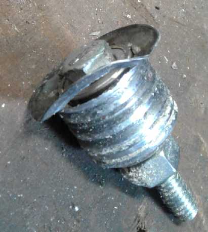
UHMW-Polyethylene Main Wheels
 With the
sawdust, gummed up with spruce pitch, sticking to
the main wheels I thought perhaps I'd try out UHMW wheels after all.
Not much of anything sticks to UHMW. I was afraid the band would slip
on the driving wheel, but it's a large surface area and it'd be worth
trying. And the undriven wheel would be fine regardless. (Presently if
the band is jammed the V-belt (a "link belt") from the motor slips.
That's probably about the best thing to have happen.)
With the
sawdust, gummed up with spruce pitch, sticking to
the main wheels I thought perhaps I'd try out UHMW wheels after all.
Not much of anything sticks to UHMW. I was afraid the band would slip
on the driving wheel, but it's a large surface area and it'd be worth
trying. And the undriven wheel would be fine regardless. (Presently if
the band is jammed the V-belt (a "link belt") from the motor slips.
That's probably about the best thing to have happen.)
I looked in my collection and found two round pieces of
UHMW about 9.9" in diameter. I could hardly believe my luck - how could
I ask for better? But instead of
being 1.5" thick they were only .85" - barely wider than the .75"
bands. It wouldn't take much mistracking for the band to come off those
wheels. But then, just possibly if it mistracked forward, it might fall
off just before the teeth hit metal and got dulled. That could be a
nuisance, but it would save bands! Being denser, the UHMW wheels were
almost identical in weight to the 1.5" wide plywood wheels.
Another thing about thinner wheels: In videos on youtube,
bandsaw experts were saying that the teeth should track just ahead of
the center of the "barrel" bulge on the wheels. What, then, was most of
the front half of the wheel for if the whole band was always to be
behind it? It just made sense that it wasn't needed. The wheel could
have its greatest bulge near the front, and most of the band should be
behind that. That should be as good as a wider wheel with the center of
the bulge in the middle.
 I decided to
try one as the undriven wheel and see how
that went. (18th) I couldn't find anyone with a lathe and a chuck that
could hold a 9.9" piece from the outside. So I drilled four holes and
mounted it on a plate on my own lathe. That wasn't very good as I
couldn't quite get it centered. (How is it I keep ending up needing to
turn 10 inch rotors of one sort or another? At least it has a "gap"
that will actually hold 10" diameter, if only barely and usually with
contortions to get it mounted.) I had to turn it down another 1/8" or
more after I cut the center hole to get the outside concentric with the
center. It's not much, but it meant I had to put in washers under the
bearing holders to get the bottom of the wheel even with the band guide
wheels. Or at least it should have. When it was assembled I eyed
it up and decided it looked pretty close. (Was the previous wheel
actually a bit too big?)
I decided to
try one as the undriven wheel and see how
that went. (18th) I couldn't find anyone with a lathe and a chuck that
could hold a 9.9" piece from the outside. So I drilled four holes and
mounted it on a plate on my own lathe. That wasn't very good as I
couldn't quite get it centered. (How is it I keep ending up needing to
turn 10 inch rotors of one sort or another? At least it has a "gap"
that will actually hold 10" diameter, if only barely and usually with
contortions to get it mounted.) I had to turn it down another 1/8" or
more after I cut the center hole to get the outside concentric with the
center. It's not much, but it meant I had to put in washers under the
bearing holders to get the bottom of the wheel even with the band guide
wheels. Or at least it should have. When it was assembled I eyed
it up and decided it looked pretty close. (Was the previous wheel
actually a bit too big?)
I took the saw out to the big cant. I only cut a couple of
inches when the band came off. My first thought was that the narrow,
slippery wheel was just going to mistrack and be a lot of trouble. But
on closer look, it was still on that wheel! It had come off the plywood
wheel, and there was an unrelated cause. When I welded up the small
"railway wheel" band guide wheels, I had used one thick washer, and
being unable to find another, one thin washer. The thin one wasn't very
strong, and had worn some. Now it had partly ripped away from the
wheel, allowing the band to come off the back of the wheel. (I was in
fact surprised that the band hadn't snapped.)
 So I had to
clean up the left guide wheel on the lathe and
weld on a new washer, then clean up the inside face again and put the
bearings back in. (19th, PM) The washer and hence the outside rim was a
little smaller, but thicker - now pretty similar to the other one. I
took the mill out and cut a couple of
slices off the top edge of the waiting cant. It cut well. It showed
little sign of mistracking and there was no indication the band might
come off. At one point it was tracking forward a little. Scraping the
sawdust accumulation off the plywood wheel fixed it.
So I had to
clean up the left guide wheel on the lathe and
weld on a new washer, then clean up the inside face again and put the
bearings back in. (19th, PM) The washer and hence the outside rim was a
little smaller, but thicker - now pretty similar to the other one. I
took the mill out and cut a couple of
slices off the top edge of the waiting cant. It cut well. It showed
little sign of mistracking and there was no indication the band might
come off. At one point it was tracking forward a little. Scraping the
sawdust accumulation off the plywood wheel fixed it.
The two cuts were a little wavy, which I realized was
partly because of big, hard knots, but more because the saw was still
set for 13" wide cuts and I was only cutting 6-8". So there was a lot
of band between the guides and the wood.
I cut the rest of the cant to 6" wide with the chainsaw
mini-mill, reset the saw for 6" wide cuts, and cut two more 2" x 6"es.
They too cut well, and I was still using the same second band from the
new box of five - for much longer than most, perhaps because I kept
scraping the sawdust off the wheels to keep them from tracking the band
forward into the nylon protector spindle, and into hard metal once it
had cut through that. And perhaps because there was no sawdust buildup
on the band. One reason for this might be that the wood was drier.
Finally it was plainly getting dull, but it had cut a lot of square
feet of spruce.
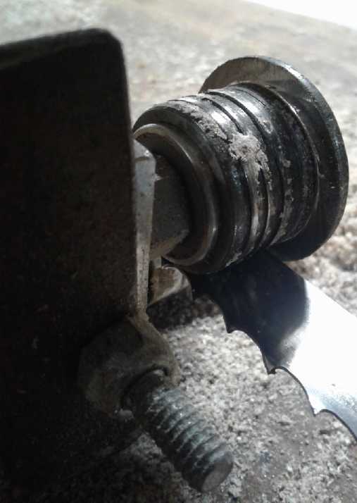
But there was no buildup of sawdust
on the UHMW wheel, while the plywood wheel had accumulated yet another
layer since the last scraping. And so another likely reason the band
had no buildup of glued-on sawdust was because one of the wheels was
helping to shed it. So it was definitely a keeper!
It seemed that if both wheels were UHMW the whole headache
of accumulation of pitch and sawdust, even on the band, would be
eliminated. That would definitely make the mill easier to use. It
seemed to be the wheel material of choice. I would definitely try the
other wheel too. Only if the drive wheel slipped would I not use it for
both.
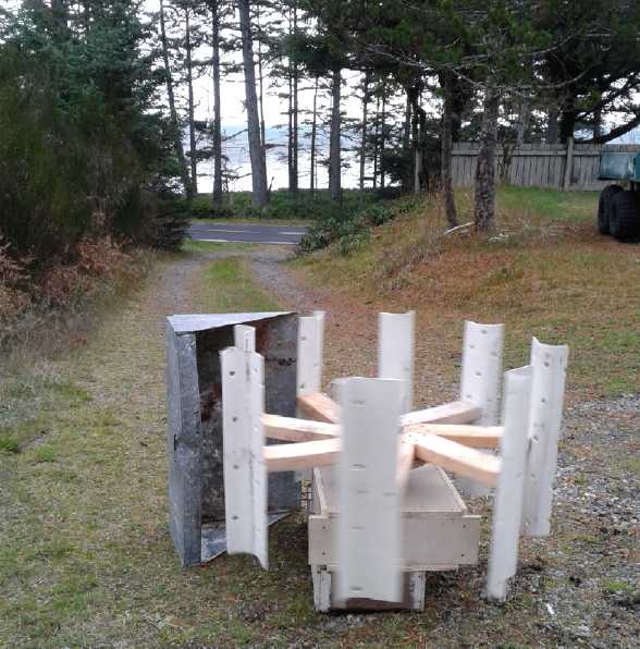
Instant Firewood Shed
On the 21st, having disposed of the lumber, I cut and
cleaned up firewood. I was throwing it in a trailer box... but then
what? I told my neighbor I had nowhere to stack it, the wood shed being
full. He said he had seen someone simply stack firewood against a tree
making a ramp with the high end against the trunk. He said he thought
that was
odd, but the man pointed out that it doesn't usually get wet right
under a tree. The water mostly falls around the outside of the
branches. That sounded good to me and I stacked it against a spruce
tree behind the house. A fierce gale blew the whole pile over (many
short, irregular pieces) and I had to restack it - this time not as
high, in two ramps.
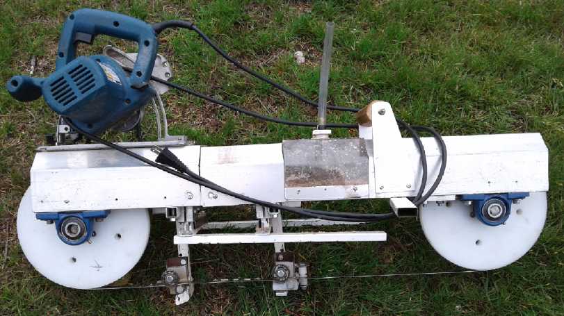
Second UHMW Wheel and (of course) More Cutting
The mill with its new "Racing Slicks" wheels
On the 22nd I made the
second UHMW wheel and installed it,
along with a new band - the third one of the five. I tackled a 15 inch
diameter by 9 foot long knotty spruce log. On my first attempt what I
feared happened: an inch into the wood the driving wheel started
slipping, and then the band came off the wheels. But I thought it
probably didn't have enough tension and I tried again with more. This
time it worked well.
I cut off a bark slab and then another slab. The second
one was cuts of 9 or 10 to almost 12 inches wide and it went rather
slowly even with a new band. I was pressing the limits the farthest yet
do this diameter of log, but it cut it.
There was no sawdust collecting on the wheels (Yay!), but
the inside of the band got quite a layer, and notwithstanding the wide
cut, was probably part of the reason for the slow cutting. (I think
cutting the bark brings lots, along with goo to stick it on.) The
outside of the band was clear - nothing presses the sawdust against it.
I scraped it off with a chisel (a stiff brush did nothing) and then
squirted on some "Armorall" protective coating to make it slipperier -
again suggested by my neighbor. That seemed to help.
Then I turned it 90° and cut a second face. I hit it
just right, with just the tiniest bits of bark showing at the finished
corner.
What next? Hmm... tomorrow! I worked on the wind turbine
most of that day (23rd), but I did cut a couple of slabs having one
straight edge. The cuts got thicker and on the second one I was cutting
8" wide for half the cut and 10.5" wide for the rest. It was slow
going, but it went smoothly without incident. Arguably I should have
cut the other side of the log square and cut 2"x8"s with straight edges
- and with less width to cut. Nonetheless I finished it up with
bark-edge boards on the 25th: one more 9-10" wide board, and then four
6-7" boards by turning it the other way up after getting 3/5 of the way
through. Doubtless the cutting was getting a little slower. I figure
1.5 to 2 times as much power would be helpful once the bands become
less than "super" sharp with use - especially for wide cuts. But then
it wouldn't plug into a regular wall socket... and a cheap
mass-produced skillsaw wouldn't work for a motor. You'd be into a
custom motor of some sort for far more money. (One of my Electric Caik
motors still comes to mind for my own saw, but I don't think I want to
get into manufacturing them.) I made considerable use of the "zig-zag"
technique of moving one end of the saw forward at a time. And wedges
behind in the cut to keep it open seemed vital. Otherwise the cuts
often seemed to close in and finally jam the band. or at least make it
hard going.
Then I cut another 10 foot piece off the small end of the
big log and milled a flat edge with the big chainsaw in the
"mini-mill". (My potential customer wanted many 10 foot 2"x6"es.) It
seemed awfully slow going compared to the bandmill, and I had to remind
myself I was cutting 16(?) inches across instead of 6 to 10 inches. It
was also unpleasant breathing hot exhaust that was also almost burning
my hand. And it was hard pushing and the chain was exposed if my hand
should slip. I didn't much care for the arrangement. Maybe I'll at
least make an "Alaska" type mill from pieces of wood, as I've seen on
Youtube. (or borrow one again, as I did last year.)
 I set up my video recorder on a tripod and took
footage to make a new video to
I set up my video recorder on a tripod and took
footage to make a new video to
put up on youtube. When it's uploaded it'll be called "Carmichael Mill
Update".
On the 28th a neighbor came over to see the mill in
action. In the course of things he said I should take the bark off the
spruce. When these trees were growing there weren't many on the other
side of the highway, and in high winds beach sand would blow across the
road and embed itself in the bark, and even get into the wood. That
would have a bearing on why my bands dulled rather quickly. I got out a
flat end shovel that I bought and sharpened the end of about 41 years
ago for scraping bark off logs (believe it or not), and used it. With
the trees having been
down for a year and a half, it came off easily in big chunks. We cut
into a big cant from the main pile, but the band seemed to be getting
dull - the cuts were getting wavy. (OTOH the waves were at big knots.)
The next day I changed the band and
finished it off, a total one might describe as seven 12 foot 2"x6"es.
With the new UHMW wheels there has been no notable
mistracking or other band or alignment problems. It works fine with the
rigid band tension adjustments that didn't seem to be good enough
before. In fact, it's cutting great! Most of my stopping is to put
wedges into the cut behind the saw because it's closing up and jamming
the blade.
Production Model Design?: Keep as is!
I had been thinking that for a production model I should
make it easier to change bands by having the axles go only one
direction to leave a space in the other for the band to slip through,
like on most shop bandsaws. But when I thought to try actually taking
the bearings off one side instead of unscrewing the covers in order to
change the band, I realized the band would also hit the assemblies that
held the band guides and the depth set glides. Removing those
would be more difficult than removing cover screws, and worse, it would
mean readjusting their positions on reassembly. Altering them would
involve the whole design of the saw - and make it weaker. So I decided
to
keep it as it was, and maybe reduce the number of cover screws a bit.
This doesn't mean I don't have a page long list of small
improvements to be made, a "deficiency list" in the sense that I've
thought of ways to improve various details and would make various
pieces somewhat differently next time.
One notable change I would make: The bearings for the main
wheels center about 1.5" below the "backbone" bars. I hadn't allowed
for the thickness of a guide board on top of the work, which may 2" or
more thick. This, plus the sideways skids adding another 1/2" of
material, reduces the available board cutting thickness from the
intended 4.5" to about 2" or even less. I would prefer to position them
about 2.5 or 3.0" below to allow thicker cuts. That also makes the top
covers over the backbone an inch (or 1.5") shorter. The top of the body
would still be 10" plus clearance above the bottoms of the main 10"
wheels.
I thought that the best way to do this would be to machine
some special bearing mounting pieces with more height. But it occurs to
me that it might just be simpler to use the store-bought "pillow block
bearings" (or "steady bearings", which I've just discovered are
virtually the same thing) and have 1" or thicker blocks of UHMW (or ?)
between them and the
"backbone" rails.
I've also found there are situations where, to get a
straight edge, it would be nice to cut down the width of a board, eg
6", rather than just the thickness. I think that would need some
redesign. Instead I have to use a chainsaw on the mini-mill.
Making most of these changes would be best done
on a
new saw. This one is cutting great, and I have a lot of cutting to do!
(And a
gear (plastic!) has broken on my milling machine. I hope I can get a
new one! Until then I won't be doing much machining.)
I ran across some lighter weight bearings for the main
wheels: "steady bearings" are like pillow block bearings but are made
of pressed metal instead of cast. They were similar high quality needle
bearings. They should take a bit of weight off the mill! Too bad I
found them right after getting an order at Princess Auto, but I ran
across a 1" size when I ordered and I got one. When I saw it I knew it
was what I wanted - four of 3/4" size for a mill. I couldn't find them
under "pillow block" bearings,
but I eventually dug them out with 3 or 4 searches. What I was missing
was the very different name, "steady bearing" instead of "pillow block
bearing". That's just confusing! So much of the difficulty in getting
the best parts to make things is in knowing where to look and its usual
unusual name.
They were on "clearance", presumably discontinued. I
wonder if that's because, like me, no one was finding them even when
they would have been the best choice? The store's web site isn't very
well organized.
The Kit!
I took the saw to show someone who uses many bandsaws and
specially made tools in his business on the 26th. He was impressed by
the saw but he didn't know of any better blades I might use with it
unless I made it bigger - bigger wheels and more power. If I made it
bigger, It would be too heavy to be handheld. But he had the great idea
that rather than making whole bandmills, I should just make kits of the
essential custom parts. Sell those components for less and let the
customer get the stock items and the skillsaw themselves. He thought
there'd be a great market for that, for people who wouldn't buy a
sawmill just because they occasionally had a tree to cut, but who would
love to mill it if they could. That sounded like about the market
I was aiming for when I designed and made it. But I hadn't considered
the kit idea.
A kit shifts main liability for injury from the
manufacturer to the person who put the kit together. If someone had an
accident with a new type of saw, in spite of doing my best to make it
safe I could theoretically end up penniless and homeless - or if I did
it under the auspices of Turquoise Energy Ltd, at least all my assets
(tools, equipment) could be seized. If I took out insurance it would
doubtless kill any revenue generated from even several saws. (Here's
another place where the already rich have it over someone trying to get
a new idea going. They would simply have it mass-produced in an
existing factory and would be able to afford any occasional lawsuits as
incidental expenses.) With a kit, that liability is largely shifted to
the kit builder, especially if I only supplied the plans and some of
the parts; the critical ones. And having put it together the user will
know and understand the tool better.
Electricity
Generation
How Not to Build a Vertical Axis Wind Turbine ("VAWT")
Whenever I did think about this project I had been all
along trying
to think how best to mount the 8 PVC vanes I had done long ago for a
VAWT. (TE News #68, Sept 2013) I wanted to be able to adjust the angle
of attack, because I didn't know what angle would work best. But their
curved shape didn't lend itself to mounting flexibility.
Having now made the Piggott alternator, and not wanting
the whole month to be almost entirely about the bandsaw mill, I had
been thinking about it again.
It would be simple to mount the generator on the roof with its axle
sticking up. The 22nd was blowing a howling gale (but no rain!) and I
wished that I
had already made it to see how it would do in a strong wind. As I
thought about this, I thought that I could screw
them to triangular pieces of wood or plywood, which could then be
screwed to a
central plate at a range of angles to see what worked best.
Another idea was that they might pivot dynamically. They
would be in
"least resistance" position as they came forward. Then when they passed
the center, the wind would push them around to "most thrust"
position. Around the back they would (suddenly?) return to "least
resistance". Another feature of this would be that as wind increased
and the unit spun too fast, the centrifugal force could overcome the
wind force and prevent them from retracting to "most thrust" position,
thus regulating the maximum speed. (Or vise versa, that centrifugal
force would keep them in "most thrust" position on the wrong side of
the turn; either way slowing it down.)
This idea required more sophistication than I was ready to
try out, and I haven't followed the blades around the circle to how see
exactly how it would work (I simply presume it could), but mounting the
blades on the separate pieces would be a
way to enable an upgrade later.
Initial Theories
The area of wind being captured would be: .56 m * .86 m =
.48 sq.m. Shall we call it .5? The total energy of a 14.4 KmPH wind
(see TE News #82 for more about wind power) would be:
W = .5 M V^3
where W is watts, M is the mass of a cubic meter of air in kilograms,
and V is the speed of the air in meters per second.
= .5 * 1.2 Kg/m^3 * (4 m/sec)^3
= 38.4 W/sq.m
Since it's 1/2 a square meter, that's 19.2 watts.
A Darius rotor is at best around 30% efficient. We'll call this one 26%
just for argument's sake. It works out to 5 watts. Of course, that's
the "cut in" wind speed. If the wind is twice that speed it would be 40
watts, and for triple, 125 watts.
Oh well, it's really just a demo. If I'm lucky the 14.4
KmPH wind will overcome the generator's bearing friction and it'll
turn. If I'm even luckier the vanes won't fold up or rip off in a high
wind.
The next day (24th) looked like a 135 watt day. The chart
in TE News #82 says a Savonius rotor should turn at about the speed of
the wind. How fast would that be if the wind was 12 meters per second?
* Circumference = π*D = π * .86 = 2.7 m.
* 12 m/sec / 2.7 m/Rot = 4.44 Rot/sec
*
4.44 Rot/sec *
60 sec/min
= 266 Rot/min
We know from the Piggott generator data from last month's
issue that the open circuit voltage output at that speed will be about
7.7 volts between any two phases. Multiply by square root of 3, or 2 *
sine 60° (= same number: 1.7320508), is 13.3 volts for the three
phases combined, which (IIRC) is also the DC voltage if they're all
rectified. Not very high! Especially if two diodes lose 1.3 volts from
it. Then just 12 volts DC. That should power some headlights for a
demo, but it wouldn't be charging even 12 volt batteries. For that it
should work okay in a howling gale!
Oh well... repeating myself, it's really just a demo!
Construction and Testing
On the 23rd it was raining in the morning and I decided
(instead of milling logs outdoors) to
try making the vertical wind turbine (VAWT) with the rotor blades made
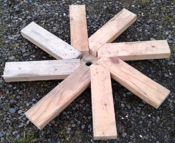
from scrap PVC pipe so long ago. I had intended to cut a big plywood
center piece to attach
to the generator axle. I went out to the shop and there were the now
scrap
1.5" thick by 10" plywood bandsaw wheels with ready-made centers, just
replaced by the UHMW ones. Nice and fat! One of those would be just big
enough to screw eight 2"x4" "spokes" to if I cut the inner ends pie
shaped. These could hold the eight vanes.
The original axle fitting for the wheels was a 3/4" inch
"H" hub. The generator had a 1 inch shaft. I found a 1 inch "H" hub and
put it on one of the wheels. There was a whole job reduced to a few
minutes!
Rather than triangular pieces, I just cut eight 7"
rectangles
of 2"x6". On a corner of each one I placed a vane and drew lines where
to cut the curves with the shop bandsaw. Since the vanes were like
snowflakes (no two quite alike) I numbered them and the wood pieces
they matched.
Then I cut the "spokes". Without any particular plan I cut
them 13.75" long. Instead of cutting a 22.5° angle on each side I
made one 45° cut - easier to get the angle right. Since they didn't
come right to the center the overall diameter was 31". With the vanes
on the ends, it would be about 34".
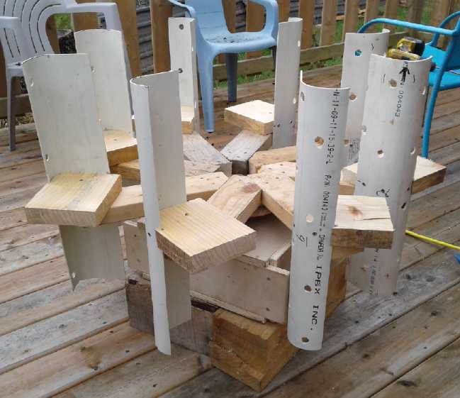 In a day I had
it done, and I mounted it on top of the Improved
Piggott Alternator I made in September. But it didn't perform well. I
tried various angles of attack for the blades, but in the howling gale,
it never got turning faster than LP phonograph speed (33-1/3 RPM). That
was with the blades at about a 90° angle from what I had intended.
In a day I had
it done, and I mounted it on top of the Improved
Piggott Alternator I made in September. But it didn't perform well. I
tried various angles of attack for the blades, but in the howling gale,
it never got turning faster than LP phonograph speed (33-1/3 RPM). That
was with the blades at about a 90° angle from what I had intended.
At that speed it didn't put out enough voltage to consider
connecting any loads. (Of course, it did seem there was more wind in
the treetops than down at the ground. Predictions were for 105 KmPH
gusts, but I don't know what they really were, much less what they were
on my porch. I had a cheap handheld anemometer... somewhere. haven't
seen it in a year or more. Probably in some cluttered crevasse
somewhere.)
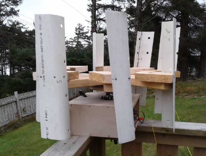 This blade angle, flat face out, worked better
- at least it turned!
This blade angle, flat face out, worked better
- at least it turned!
The apparent tilt of the blades is a camera illusion: they are rotating
counter-clockwise and as the
cell phone (camera) scans from top to bottom, they are turning a little
farther and farther.
About the only thing that seemed positive was that the
blades were easily detached. On the 26th I went back to youtube. I
found the VAWT I was trying to copy when I formed the blades in 2013. I
had them inside out - the concave face was supposed to go outside, not
inside. I checked over what would strike what in rotation and it was
fine: the blades would clear the corners of the generator and so it
would be simple to turn them around 180 degrees. So I
did that the next day. Again there was a good wind, but again results
were poor - perhaps worse. (Someone on youtube with similar blades who
also tried different angles thought it was a little better this way
out.) I taped over some of the holes in the plastic, without noticeable
results. But I wasn't convinced the location was
good.
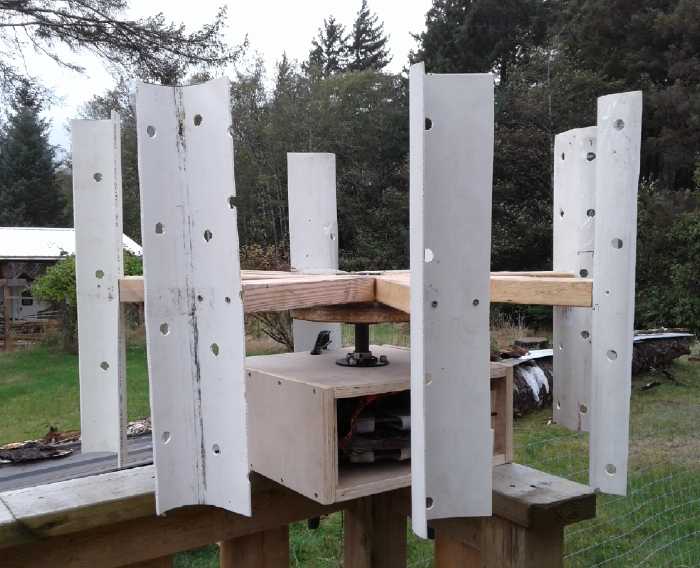 Blades Reversed (screwed right onto to the
"spokes")
Blades Reversed (screwed right onto to the
"spokes")
I wandered around the yard and found there was a steadier
breeze
coming up the driveway. I moved it down there and got 30-40 RPM. Then I
put up a "wind shield" in front of the side that was moving forward,
toward the wind. That seemed to double the speed to 60-80 RPM.
Sometimes it would read 90 or 100. I also tried putting the wind shield
behind the unit, on the theory that the wind would have to stop either
way, but it was much less effective there. Some have put angled
deflectors around the outside of the spinning part and achieved similar
results. Those are probably better: my wind block would have to be
moved for different wind directions.
I should also note that the square 2"x4" spokes can't be
helping achieve good speeds - they're not aerodynamic at all!
The driveway seemed to be a "wind funnel"
 At higher RPM the camera trick of "tilted
blades" (now rotating clockwise) was more pronounced
At higher RPM the camera trick of "tilted
blades" (now rotating clockwise) was more pronounced
Connections & Meters
At 60 RPM it put out about 1.5 volts AC across two phases.
(It was hard to tell - at 6 Hz the meter readings pulsed wildly up and
down.) That should end up at 2.6 VDC after rectification... not
counting losing ~1.3 volts in the diode bridge. If shorted it would put
out about 2.5 amps at first, but the unit would slow down after a few
turns until there wasn't much. A 1 ohm load brought the voltage down to
a volt and dropped the speed perceptibly. (The reduced voltage caused
the RPM/Hz counter to quit, so I couldn't tell how much slower.) The 1
W probably wasn't the "maximum power point", but
it seemed like a lot of bother for a watt or two!
The unit may be a meter wide, but it's only the segment
that's moving across or away from the wind that gives power. The other
half is just a drag. So presumably one must cut the wind frontage area
used for power calculations in half.
Some Conclusions
I found other VAWT videos by the same author, mostly from
around 2011. He kept changing them, experimenting. A couple of others
had vanes to redirect the wind, similar in effect to my wind shield,
and one of these he gave readings for had almost similar speed
increases over no vanes.
Moral: don't assume just because it looks well made and
professional, of welded stainless steel, and the builder was excited
about it when he did the video, that he had the best design. I hadn't
given it much study and was more interested at the time I made the
vanes in the fact that PVC and ABS plastics could be shaped by heating
them in a kitchen oven until they became soft and pliable. But a couple
of other people on youtube used similar vane shapes, too.
The
traditional "two halves of a barrel" Darius rotor has the advantage of
creating its own higher pressure area in the middle behind the half
moving upwind, which doubtless improves its performance. One I saw on
youtube seemed pretty lackluster, but it's hard to know what the wind
speed was. One with many thin
propeller shaped blades - made from 'wing profile' baseboard molding -
seemed to work well. In fact the blades were so close together that
each one probably angled the airflow so it helped the next one to work
better. Perhaps that would be a good design to try?
The other thing that can be tried is the hinged blades
idea, blades that
feather themselves facing into the wind and "flip" to provide best
forward lift on the with-the-wind side. That might be as good as or
better than the wind shield, barrel halves, or outer stationary
redirecting vanes. Again, if one is serious, various designs deserve a
lot of study. The Tesla Turbine with a "horn" to direct the wind into
it might still be a good idea. (TE News #106) But at some point of
complication, a horizontal axis with a propeller may be a more
productive route.
This project was a side venture. I wanted something just
to turn my new generator, but at the speed it went, the generator would
have to have far more turns of much finer wire. It wouldn't be hard to
wind a new stator, but even then it
wasn't going to have a lot of power at such low RPMs. Most small VAWTs
on youtube didn't seem to have much power either. If I was to get
serious about it, I'd look more carefully into how to reliably get the
most energy output from the wind with a VAWT, and wind a new stator for
better voltage. And more than anything I'd try to find the best
location I could. Just
moving from the porch to the driveway made a tremendous difference -
with a southeast wind. It was on the ground, and of course in general
the higher up one mounts it, the better it is.
I won't rule out further explorations. It did at least
work, so it does have potential. But it may not be the best thing to
put too many watts of my own energy into.
Solar Panel
Rewiring
On the 3rd I got around to rewiring my solar panels. The
"1000 watt" grid tie inverter putting out only ~420 maximum watts meant
half my
1000
watts of solar panels was going to waste on the best days. (all this
sunny summer!) But it seemed reliable and good value for the low price
even for 400 watts, so I ordered two more the same to get up to 1200
watts. They arrived in late September. I decided to mount them on the
garage
wall right below where the solar panel wires came down.
First I went into the attic. I drilled a hole for another
wire. One wire fit in the old hole beside the original wire, which I
didn't remove, so one new hole for two wires. The old wire will be good
for running low voltage DC circuits across the house. So
two new wires only around 10 feet long went from the solar wiring box
down the
wall. I separated the panels into two sets of two instead of all four
in parallel.
Then I put up a piece of 5/8" "fire stop" gyproc on the
garage wall so the equipment wouldn't be making heat right against the
cedar siding wall. (If this garage ever catches fire it will spread
really fast. What were they thinking when they made garage interior
walls from
cedar?) Then I screwed
the inverters onto it. Then I wired the panels to the inverters and
plugged
them into an AC outlet. (...or should I call it an AC inlet since the
power goes the other way?) I used AWG #14-3 that I had lying around.
With three insulated wires plus the bare ground wire, I doubled up the
wires, effectively making them #11 gauge.
With a few
distractions it had taken all day and by now
the tree shadows were across the roof so I left it until morning. Then
I turned them on and took some readings. Only 5 amps out of 15 or so
max were
going from the panels to each inverter. It was still early, but that
seemed pretty weak. I looked outside and sure enough wispy high
altitude clouds, spreading jet trails everywhere - "chemtrails" - were
dimming the sun. (After a record hot summer globally, with droughts
and hail causing worldwide crop losses and failures, there are now
predictions
for a really tough, cold winter which started early in some places
causing
further crop losses. Yet still they spray, ostensibly to
cool, on and on. How
can these people have any idea what they're doing?)
A while later they had thinned where the sun was and it
was up to 8.6 amps from one and 9 amps from the other. (The 4 panels
are not identical. Something like 240, 250, 260 and 260 watts. I didn't
look at the specs on the back or care which order they went up in.) The
MPP voltage being about
28.6 volts, with a .7
volt drop in the diodes and 1 volt drop in the wires to about 27, that
was 232+243=475 watts - already over the 420 watts total that one
inverter would put out. It was still pretty early, but a set of four
spruce trees soon started casting their long shadows across the roof
for a couple of hours and I was glad to have get positive readings
without waiting around until afternoon. (For half the year those tree
shadows don't reach the house. But in winter at 53.5° north the sun
gets pretty low.) On the 6th just before it clouded over I measured
(9.6 A + 9.5 A) * 27.6 V = 527 W going into the inverters. So maybe
around 500 watts coming out. At least it was a little more than 400.
But it looked like that would be about it until spring and a higher sun
angle.
On the 10th more ideal conditions appeared once the panels
were out from the tree shadows. a combined 21 amps in (10.4, 10.6) at
27.2 volts was 571 watts input. I put a "splitter" (here really a
"combiner"?) in the AC line and the AC output amps from both panels was
up as high as 4.33 amps. At 120 volts (not measured), that's 520 watts,
which is 100 more than I ever got in the summer with a single inverter
on all four panels. Then jets bearing chemtrails went by and the
readings started to drop.
(At least, it was 520 volt-amps - The power meter earlier
had shown that it isn't unity power factor. It makes sense that if the
grid tie inverters only put out power when the grid is "live", they
have to delay to see voltage each half cycle before they start
outputting current.)
A side note: I hadn't liked the noisy fan coming on and
off when I had the first inverter running in the house. It was sitting
flat on the floor. Mounted vertically on the garage wall the fans seem
to never come on. Being fall the garage is now cooler, but I think
mainly they must have enough air cooling them by convection that the
fans don't need to run.
On the 13th my order of two constant voltage charge
controllers for solar for the electric vehicles, and five PWM charge
controllers
for general 12 volt battery charging arrived.
Tidal Flow
Power Unit: Cheaper, Better!
Cheap
Floating Power Vessel Hulls?
I drove to Masset on the 26th. On the way out of town
passing by Coastal Propane my eyes caught a glance of a field
of a few dozen propane tanks including the big, horizontal ones
that hold hundreds of gallons. They sit stationary and propane is
delivered to them by truck. Some of
them had rust streaks and it looked like they were discards.
Now then... What was that that the hull of that tidal
power unit in the Orkneys was made of?... sections of steel pipe welded
together. Here were dozens of steel pipes. Just cut the ends off
(except the ready-made ends for the front and rear one) and weld them
together! Presto! There were the "half made" hulls for tidal power
units and perhaps some of the venturi parts as well, probably all to be
had for scrap prices - maybe even free? Plus delivery, sand blasting,
welding and repainting, of course.
I turned around and drove back to the office but it seemed
they closed at 4:30 PM. It was 4:39. Oh well! I phoned a couple of days
later and was told the tanks, while many of them were discards as
propane tanks, weren't free. People bought them for floats and other
purposes. They were good steel, already here on the island. Generally
they were "50 ¢/gallon" for larger tanks.
But I made it back up to Masset on November 1st (to settle
the trucking bill for the solar panels), and the owner or manager came
out with me and we checked it out. There were a bunch of smaller tanks
for free, "500 pounds" IIRC. They weren't very tall and I thought of
all the welding that would need to be done to put a bunch of them
together to make them long enough. Then I looked at the biggest one,
1160 gallons. (Canadian gallons, or US?) It was a discard only because
someone had welded legs onto it, and it was illegal to fill propane
tanks that had welding done on them after manufacture. It seemed to me
that might just be a pretty good size by itself without having to add
anything more. It was 18 feet long and 42 inches in diameter - big
enough to get inside if a hatch was made and - hopefully - long enough.
It was less than 10% of the length of the ScotRenewables one in the
Orkneys, but it was to be 100 KW, just 5% of that 2 MW Scottish one.
500$.
So, there was a good central hull, made but of course
still needing to be fitted out. In the second design for the Orkneys,
the power producing units were to just barely float by themselves. They
would be floated up to and then bolted to the central hull, one on each
side. This seemed to me to be a good arrangement. Two or three
different designs could be tried out and the one that was liked best
could be duplicated.
I had also come up with some vague plans in my head for
the propeller unit - and even ordered a part. In my plan, the propeller
would be at the rear of a sealed stainless steel hub filled with oil
just like an outboard motor propeller. As a better, low-loss
connection, a single universal joint would attach to the front of the
shaft and its shaft would feed through a pipe (with the U joint in the
oil) at 45° (or less). The top end of the pipe would enter the
vessel near
the front, and the generator would mount tilted at 45° to match, or
else another universal joint would make the shaft horizontal again. Or,
two might be employed to turn as far as 90° and make the shaft
vertical or at least more vertical than (max) 45°.
I
had ordered a "generic" U-joint for 1 inch keyed shafts from Princess
Auto. On the same day I
had run into drawings for an automotive universal joint, similar to one
I had been shown for the Chevy Sprint car drive shaft when I put the
forklift motor in it. If the Princess Auto one proved unsuitable, the
automotive ones just might fill the bill? Or a CV drive shaft... like
the spares for the Sprint, already sitting in my dungeon... I mean,
storage room? (NOW I think of that. Oh well, nothing's been
built yet.)
A separate idea to simply use the bottom end of some old
outboard motor later came to mind, too. But they aren't made for
propeller diameters like a meter or so.
Ducted Fans & Venturies
I also found a youtube video explaining why a propeller in
a duct (even without the venturi effect) works better than one in free
air (or water). This is applicable to both a floating hydro vessel and
to a ground effect vehicle with a "ducted fan" propeller.
First, the outside pipe prevents the air (or water) under
differential pressures from flowing freely around the outsides of the
propeller tips from front to back (for energy capture) or back to front
(for thrust), which wastes substantial energy (and makes them noisier).
Second, a forward facing "semicircle" entry widening the
front of the duct brings in more air at
lower pressure. It would seem it's partly a wing "lift" effect and
partly a venturi effect. It would seem the already wider opening into a
venturi tube would also be improved by having this shape at the front.
(I looked at the ducted fan propeller for the
radio controlled model ground effect vehicle and it didn't have this
apparently valuable component. Perhaps I could make something.)
There have been seaplanes that have used ducted fans. The
higher static thrust gave them more power for take-off from the water.
Reasons they aren't usually used in aircraft and other places: First
and foremost while it improves static thrust at low vehicle speeds, it
helps much less at high speeds, and the whole ring around the
propeller creates a lot more drag when an aircraft is flying fast - a
net loss of energy. Plus they are extra weight, and to work well the
gap
between the propeller and the outside duct has to be very small, which
means heavier construction is required to prevent any warping or
flexing that might
cause them to contact the propeller.
Fast flying doesn't apply to the water power vessel, and
in the ground effect vehicle (as with the seaplanes... were those
called "SeaBees?") as I see it, top speed is of less
importance than being able to get it to rise off the water and become
airborne to start with.
For the water power, the gap for water can also be larger
than that for air.
Electricity
from HE ("Short Space Ray", GeV) Spectral Band?
I talked with someone after
the energy symposium who brought up the subject of "unconventional"
energy units. I
went into my explanation of how the energy for these appeared actually
to come from
stellar HE radiation that shines down on the planet from all directions
but mostly from the main plane of the Milky Way. He said I was the
first person he had brought up the subject with who knew what he was
talking about.
Generators, solar panels, wind turbines, floating hydro...
all this effort... might I not be able to get a high energy ray to
electricity converter to work? I had managed to get my mind away
from this subject for
quite some time. Now I got curious again. It would be highly useful if
it could be made to work.
There was at least one thing I hadn't tried in my recent
experiments - grounding the output or other points. I went back to The
Free
Energy
Handbook to look at Tom Bearden's "MEG" Motionless Electric
Generator again. On the way there I passed by the somewhat similar Valeri
Ivanov’s
Motionless
Generator.
As usual I didn't really understand how it was supposed to
work.
But there were links to some youtube videos. I found one on Bearden's
MEG some years old now where they explained a magnetic field flipping
back and forth, and they were looking for 9 million dollars to do a bit
more development and get it into production.
Then I saw another one
by CodyGillespie from 2010 called "Switching Permantent Magnet
Field.WMV" (Note sp. to search: Permantent) that showed an
interesting
principle. If you take a bar magnet (Here a disk magnet with two metal
extension bars acting as one) and attach the points of a "U" shaped
piece of iron on one
side, say the right, it grabs on magnetically and it takes a
substantial force to pull it away.
Now take another "U" and put it on the left side.
Simplistic logic
says the flux will divide and both pieces will be held equally to the
magnetic bar. However, this is not the case. The new piece on the left
has little or no attraction to the bar. The flux lines are already
routed inside the right hand "U" and don't come out to engage the new
piece. If one forceably pulls the
right "U" away, the left one then latches onto the bar magnet. Then
it's the
right one that has little or no attraction - the Bearden flipping
magnetic field.
There was another trick. The two "U" pieces each had
an electromagnet coil in the middle. (zillions of turns of very fine
wire) The two coils were then connected with alligator clip leads at
both ends to each other, electrically in parallel but magnetically
reversed. When "north" was up on
one, "south" was up on the other. Then with two more clips a little 9
volt battery
was momentarily connected while both "U" pieces were touching the bar,
one electrical polarity or the other. One way, the left "U" would come
loose (made magnetically N-N and S-S to repel from the bar) and the
right "U" would
magnetically latch on "permanently" (made N-S and S-N). The other way,
the right one would be or would become loose and the left one would be
stuck. It was said the idea was developed for magnetic boots for
astronauts. It was rather amazing to see how the momentary pulse from
the electromagnets created a permanent effect in the fields. (Someone
told me of this phenomenon maybe a year ago - about a piece that stuck
permanently
after an electromagnet was activated. But he didn't mention the
permanent magnet, so it didn't make sense to me. Anyway I didn't know
where to look it up.)
This seemingly unrelated
video made the drawings of Ivanov's circuit more understandable. The
magnetic flux really could 'flip' one way or the other rather than be
an average of both ways, and not just
for an instant while the power was applied but in a "flip-flop" manner.
Or perhaps in this case, it
was a monostable rather than bistable flip-flop? Unless the polarity of
the coil was to be repeatedly reversed, switching the electricity would
have to make the unit flip twice, "ON" and "OFF" again.
There were two possibilities for that: one was that the gap shown on
the right would cause that field to be weaker and so it would only flip
to it momentarily when the power was on, or just as it shut off. The
other was that the toroid might be, eg, ferrite, and so magnetically
weaker itself. Then the field would only switch to the toroid side when
its coils were powered. (But if so, why was the gap on the right side?)
The information was sketchy, but it was not indicated that the toroid
was any different material. A gap somewhere usually seems to be a
feature of HE ray capture devices.
But either way, as the coil shut off there would be the
high voltage electromagnetic switching spike that might cause HE rays
to release their energy into the field of the device. Then the output
coil on the right might collect more energy than the input coil had
supplied.
It was said that ordinary laminated iron ("transformer
iron") could be used for this design.
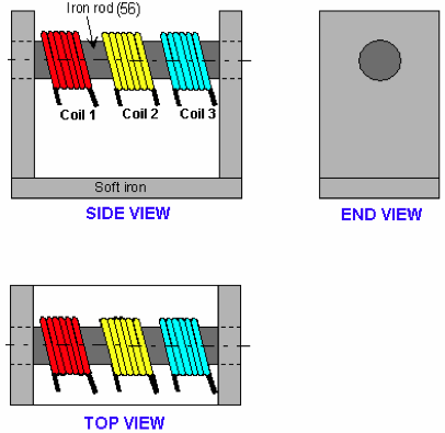 Looking
further through the book, I ran across The Michel Meyer and Yves
Mace Isotopic Generator. They certainly had a creative way of
explaining where the energy came from: that isotope 56 iron was being
converted to isotope 54 iron, which released energy. I don't believe a
word of it, but I did note the construction not only was ordinary iron
(magnetically "soft"), but that it was solid pieces, not even
transformer laminations. This seems simpler and I didn't see why it
wouldn't work.
Looking
further through the book, I ran across The Michel Meyer and Yves
Mace Isotopic Generator. They certainly had a creative way of
explaining where the energy came from: that isotope 56 iron was being
converted to isotope 54 iron, which released energy. I don't believe a
word of it, but I did note the construction not only was ordinary iron
(magnetically "soft"), but that it was solid pieces, not even
transformer laminations. This seems simpler and I didn't see why it
wouldn't work.
It was almost similar to the Ivanov device except set on
its end. Instead of an end piece, there was a bottom piece. It just
needed a permanent magnet going between the two sides and a toroid coil
instead of the three-coil bar.
For convenience the output coil could be wound around a
side below the magnet instead of around the bottom.
Design and Construction
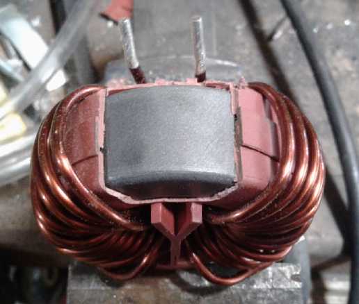 So my plan started with using
the same 570 uH toroid choke
I
had been using. Actually, the second choke since I had bought two
alike.
(8th) I unclipped the plastic bottom piece and it pulled off, leaving
the wires by themselves. I rewound it by taking one set off and putting
the two wires on each side in series. I went from one end to the other
so wires that would be far apart in voltage during high voltage spikes
weren't adjacent to each other. I decided, since the ferrite was
probably magnetically weaker anyway, to have the gap be between the
toroid and the square iron frame. There was already a gap because of
the plastic cover over the toroid itself. I cut the cover away on one
side so there would only be one gap. I think with two wires in series
and
then both sides in parallel, that should have similar electrical
resistance to the setup I was using before.
So my plan started with using
the same 570 uH toroid choke
I
had been using. Actually, the second choke since I had bought two
alike.
(8th) I unclipped the plastic bottom piece and it pulled off, leaving
the wires by themselves. I rewound it by taking one set off and putting
the two wires on each side in series. I went from one end to the other
so wires that would be far apart in voltage during high voltage spikes
weren't adjacent to each other. I decided, since the ferrite was
probably magnetically weaker anyway, to have the gap be between the
toroid and the square iron frame. There was already a gap because of
the plastic cover over the toroid itself. I cut the cover away on one
side so there would only be one gap. I think with two wires in series
and
then both sides in parallel, that should have similar electrical
resistance to the setup I was using before.
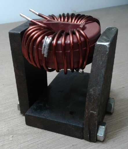 (9th)
Next I found a scrap of 1/2" mild steel for the base and
two pieces of 3/8" for the sides. Then I drilled and tapped holes and
bolted them together into a "U". If I loosened the bolts, the size was
just right to put the toroid on the top and tighten them again to clamp
it into place. The side pieces being rather short, I put the toroid
crossways instead of in-line. I trust
that should make no magnetic difference overall.
(9th)
Next I found a scrap of 1/2" mild steel for the base and
two pieces of 3/8" for the sides. Then I drilled and tapped holes and
bolted them together into a "U". If I loosened the bolts, the size was
just right to put the toroid on the top and tighten them again to clamp
it into place. The side pieces being rather short, I put the toroid
crossways instead of in-line. I trust
that should make no magnetic difference overall.
Then I got a supermagnet and cut a piece of steel to
extend it across between the uprights, making it pretty much an upended
Ivanov.
(10th) My sides were pretty short and there wasn't a
lot of height below the magnet to
wind an output coil around a side. But it seemed like enough. A big
annoyance in most of these designs is they either want zillions of
turns of very fine wire or they don't say what's needed. By just using
a toroid I had got 120 volts with a 20 turn coil. I initially decided
to make a
20 turn coil for this output as well, but it was farther around the
loop, so to have a similar length of wire I made it 12 turns instead.
Hopefully when rectified and
filtered the voltage would be something reasonable to run a load,
either 12 volts or 120 volts. If not I would change it. But I had other
things to do so that was it. I soldered on the previously used cable to
the car's motor controller to the toroid coil, both sides pushing the
flux the same direction, and the diode bridge and capacitor filter to
the output coil.
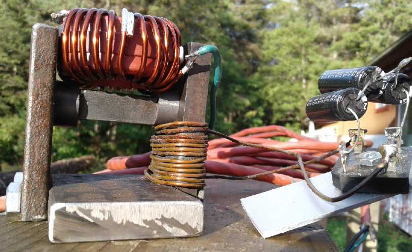 After that was done, I thought later in the day that the
electromagnetic pulse doubtless had to overpower the permanent magnet
to some extent, and this one seemed awfully powerful even for a
supermagnet. In the evening I remembered I had some ordinary cylinder
magnets among all the others, and I found them and took one. It was
shorter, but I got another one and with two it was the right length to
connect it across to the other side. Further options were to cut a
longer steel bar and have one magnets, or to have three or four magnets
with shorter bars. That gave potential choices to try out four
different magnet strengths, all of which were far weaker than the
supermagnet. Perhaps I'd be shooting for "optimum" magnet strength as
opposed to just finding one that worked.
After that was done, I thought later in the day that the
electromagnetic pulse doubtless had to overpower the permanent magnet
to some extent, and this one seemed awfully powerful even for a
supermagnet. In the evening I remembered I had some ordinary cylinder
magnets among all the others, and I found them and took one. It was
shorter, but I got another one and with two it was the right length to
connect it across to the other side. Further options were to cut a
longer steel bar and have one magnets, or to have three or four magnets
with shorter bars. That gave potential choices to try out four
different magnet strengths, all of which were far weaker than the
supermagnet. Perhaps I'd be shooting for "optimum" magnet strength as
opposed to just finding one that worked.
Again, for initial testing I could drive it from the 36
volt Sprint car controller's "field drive". Well, it didn't look like
it could get much simpler. But it didn't seem to work at all.
Considering I was using regular steel now, perhaps the frequency has to
be way lower - Hz or the lower hundreds of Hz instead of 16 KHz. And
would that provide enough impetus? Bearden used some sort of
unspecified nanocrystalline material so he could use a high enough
frequency to make his work. Anyway to try a lower frequency I would
have to make an
oscillator circuit with a high current output to drive the coil. It
could be just a single pulse output version of the one I made last
year, which needed redesign anyway. But I just wasn't into circuit
board design and microcontroller programming in October. Soon!
Rechargeable
Battery Making
with oxalate electrolyte
Another Idea for a Conductive Graphite Material?: Conductive
Polyurethane Paint
Near the end of the
month,
Leonardo sent me a link to a website called "WorkingInk.co.uk". One of
its specialties is conductive ink. A video showed making a conductive
ink from gum arabic, water, graphite powder and some miscellaneous
substances. At the end of the video he acknowledged that being based on
gum arabic it was water soluble.
But at the end he commented that if you needed waterproof
"conductive ink" you might try using polyurethane paint instead. This
struck me as being a waterproof conductive paint, and a potentially
useful idea. What I had tried before was graphite in epoxy resin to
make whole plastic current collectors. These weren't very conductive
and current capacity was poor.
Polyurethane paint (at least a can of it that I have) is
water soluble until it dries. Then it isn't. If a metal positive
current collector was painted with conductive polyurethane paint, it
should prevent the metal from oxidizing. If it wasn't perfect, for
example if the paint was scratched, in most electrolytes the whole
metal current collector underneath would dissolve. In oxalate I expect
a layer of metal oxalate around the scratch would stop further
penetration of electrolyte.
The net effect would be to have almost the conductivity of
metal
in the current collector, without the surface oxidation of the last
tested manganese electrode. The conductive paint would have better
conductivity than an oxidized metal surface, and, being a thin layer,
much better than trying to make the whole current collector from
graphited epoxy or poly-whatever. It should accomplish the same thing I
was trying to do with the osmium doped film. It probably wouldn't work
with nickel hydroxide/nickel manganate electrodes, since graphite
powder additive doesn't seem to work, but it should work fine with a
lower voltage manganese dioxide electrode.
This may inspire me to try making and trying out a couple
of new MnO2 electrodes next month!
http://www.TurquoiseEnergy.com
Haida Gwaii, BC Canada