Turquoise Energy Ltd. News #126
covering
November
2018 (Posted December 3rd)
Lawnhill BC Canada
by Craig Carmichael
www.TurquoiseEnergy.com
= www.ElectricCaik.com
= www.ElectricHubcap.com
= www.ElectricWeel.com
Month
In Brief
(Project Summaries etc.)
- Milling Trouble - New Chemie Batteries - A Better conductive
Paint - Vertical Axis Wind Turbine Etc.
In
Passing
(Miscellaneous topics, editorial comments & opinionated rants)
- America at the Crossroads: Restart and Fresh Progress, or a New
Dark Age? - NO MORE WARS! NO MORE VIOLENCE AGAINST SYRIA! -
"Proportional Representation" and the Third Stage of Democracy - The
Exponential Function & Global Growth - More California Fire
Oddities - Qualifying to Run for Office - CIA: Rogue from Day One -
Coffee Roasting - ESD etc.
- Project Reports
-
Electric
Transport - Electric Hubcap Motor Systems
* Just a bit of work on the reluctance motor
Other "Green"
Electric Equipment Projects
* Carmichael Mill Handheld Bandmill (more operating than building this
time) - Bonus Tip: stack firewood under a tree to dry
* Recycling Scrap HDPE (or UHMW, or PP?) Into Useful- (millable) Shapes
- plus: Who needs to Have a Kitchen Stove?
Electricity Generation
* VAWT Designs: A bewildering variety of blades, vanes, shapes and
designs. What's really best?
* Magnetic Flipping HE Ray Energy?
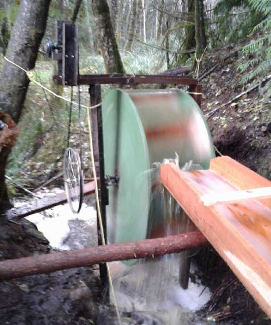
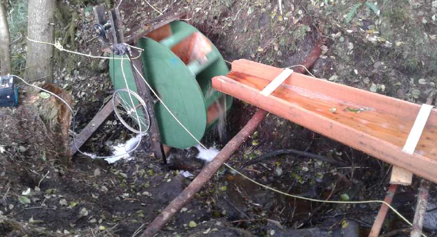
* A Water Wheel Hydro Power Project
Electricity Storage -
Turquoise Battery
Project (Mn-Zn, Ni-Zn or Pb-Zn in Oxalate electrolyte)
* Conductive Polyurethane Paint: Painted Copper MnO2 Pocket Electrode -
New MnO2-Zn
cell tests
November in Brief
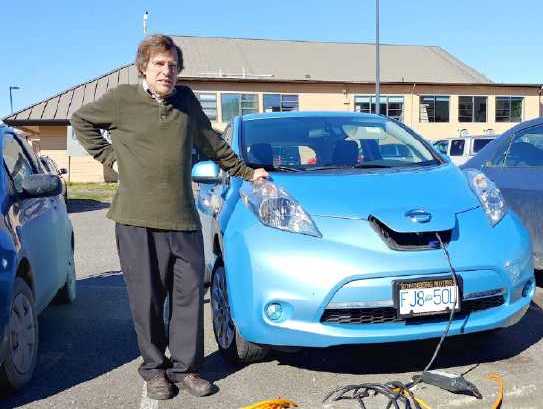 It seems a picture of me with the Nissan Leaf
made the Haida Gwaii Observer
It seems a picture of me with the Nissan Leaf
made the Haida Gwaii Observer
newspaper's article on the Swiilawiid Energy Symposium at the
end of September.
It always seems I have more projects than time to work on
them. OTOH lately I was getting some lumber milling done with my
"Carmichael Mill" handheld bandmill. -- part of September and much of
October up until the first week of November. And I'm going to want the
lumber if I decide to put walls on the roof over the travel trailer.
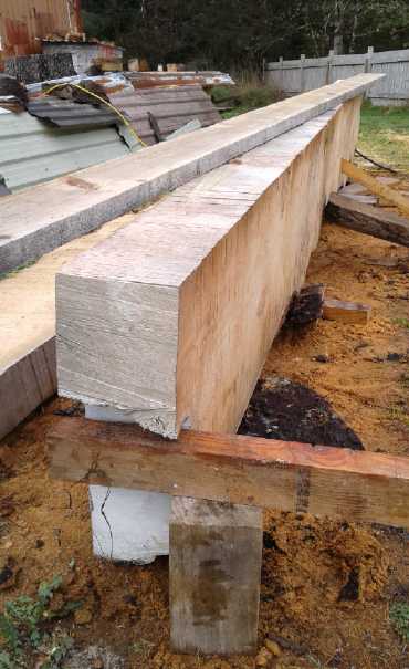
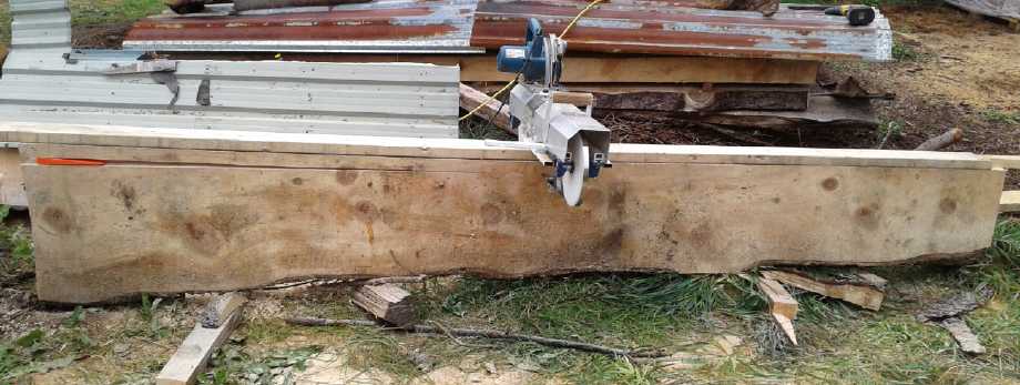 Sawing up a cant of wood (6" x 1.5" boards x
12') Nov. 7
Sawing up a cant of wood (6" x 1.5" boards x
12') Nov. 7
It was
working great until the gear teeth in the Ryobi skillsaw that was
powering it wore out. There's no way to know that the grease was
essentially gone inside the 'gear box'. Otherwise I'd have regreased it
earlier. Skillsaws are quieter than chainsaws, but they're still so
noisy you don't hear any clues. So milling came to a halt for most of
the month until I got another motor - another skillsaw. And then it
stayed halted because the weather wasn't very nice, so I didn't bother
to fix the mill until late in the month. And then I was out of sharp
bands. I started in on adapting the band sharpener, but as I feared I
didn't get the new offset cam bolt hole in the right place - twice. It
sort of worked on December 1st. The sharpened band cut better than
dull, but not well. On December 2nd I made a change and it was better.
On the 7th I started on "clean energy" projects again.
I've lost track of the timeline after that, but here are the projects:
New Chemie Batteries - A Better conductive Paint?
 Leonardo sent
me a link to a site where someone showed how
to make conductive ink with graphite powder in gum arabic. The
application to battery making was spoiled by the fact that gum arabic
is water soluble, but right at the end of his video he remarked that if
one wanted a waterproof ink one might try a similar thing with
polyurethane paint. That seemed like a great idea. My quart of yellow
PU paint was "water clean up" and could be thinned with water, but
after it dried it was waterproof. I made a copper electrode pocket,
then painted it with the PU paint after mixing in some conductive
carbon black and thinning it. To my surprise, while it clogged the
perforations in the pocket when I painted it on, they seemed to all
open up again as it dried. It came out quite thin in most areas, kind
of like an ink. One could see the copper undertone beneath. It's
probably almost ideal, and easier than the osmium doped film. Then I
filled it with MnO2 salvaged from dry cells, and crimped the edges with
a hammer and screwdriver while pressing it flat in the hydraulic press
with only a couple of tons of pressure. Somehow these little jobs to
make it were spread over much of the month.
Leonardo sent
me a link to a site where someone showed how
to make conductive ink with graphite powder in gum arabic. The
application to battery making was spoiled by the fact that gum arabic
is water soluble, but right at the end of his video he remarked that if
one wanted a waterproof ink one might try a similar thing with
polyurethane paint. That seemed like a great idea. My quart of yellow
PU paint was "water clean up" and could be thinned with water, but
after it dried it was waterproof. I made a copper electrode pocket,
then painted it with the PU paint after mixing in some conductive
carbon black and thinning it. To my surprise, while it clogged the
perforations in the pocket when I painted it on, they seemed to all
open up again as it dried. It came out quite thin in most areas, kind
of like an ink. One could see the copper undertone beneath. It's
probably almost ideal, and easier than the osmium doped film. Then I
filled it with MnO2 salvaged from dry cells, and crimped the edges with
a hammer and screwdriver while pressing it flat in the hydraulic press
with only a couple of tons of pressure. Somehow these little jobs to
make it were spread over much of the month.
Then I made another zinc electrode (started in September).
This time I cleaned it in solvent to be sure there was no chloride left
on it after etching it in ferric chloride. I sprinkled just a bit of
zinc powder inside the pocket to help ensure there was something like
enough to match
the 22 amp-hours or so of the MnO2.
I put them together and filled the cell, and did a couple
of other things after that. It was better made, but it didn't behave
much differently than with the previous electrodes. So I started to
think it must be the zinc side that was the main problem. But why? I
thought zinc electrodes were pretty much foolproof. The
month ended with the questions still unanswered.
Vertical Axis Wind Turbine Etc.
 I started
studying the VAWT idea again. I hadn't been
impressed with the "wind scoop" vane profile
performance on a VAWT. What was really the best vane shape? I saw a
video, a youtube suggestion, of a VAWT
with 8 straight vanes mounted at 45°. It seemed to turn excitedly
in what the maker said was a 1 meter per second breeze. It looked like
it was turning backward compared with what I expected. I looked up a
few more and "V" shaped vanes seemed like a good idea, which I tried
out.
I started
studying the VAWT idea again. I hadn't been
impressed with the "wind scoop" vane profile
performance on a VAWT. What was really the best vane shape? I saw a
video, a youtube suggestion, of a VAWT
with 8 straight vanes mounted at 45°. It seemed to turn excitedly
in what the maker said was a 1 meter per second breeze. It looked like
it was turning backward compared with what I expected. I looked up a
few more and "V" shaped vanes seemed like a good idea, which I tried
out.
I also had an idea to use vanes - airfoils - shaped like
venetian blinds similar to my water wheel idea from a couple of years
ago... and then to make them flat on the inside from log outside
cuttings
or "plywood peeler" boards, with a profile of a thin |) . If the
angle was 45° I could cut spoke pieces at that angle, screw them to
the
"spokes" in my center assembly, and screw the vanes, flat or "|)", to
those. That too seemed like a simple thing to do to see what would
happen. But since the whole VAWT idea seemed more and more like an
unproductive diversion, I turned to other things.
I had contacted a couple of
people in October about
support for the tidal flow power unit. Neither replied. Probably I'm
remiss in not trying a few more people, but it seems to me I've
been here before. I set it aside to work on HE ray energy
instead. I could do that without help, and if I could get something to
work, it would be the more valuable.
But then I did a bit more reading. And I thought of
Yourbrook Energy's present plan to build an upper and lower reservoir
with a hydro turbine between them. Their tidal power unit pumps water
directly, and would pump it from the lower to the upper reservoir by
tidal power. Then the turbine generates electricity at a rate where the
upper reservoir won't run dry at slack tides, providing continual power
via energy storage as elevated water.
I started thinking of all the intermittent energy sources
that are not the favorites of power companies. If an electric pump were
installed, extra power from any source anywhere on the entire grid
could be used to pump water into the upper reservoir, which could then
be drawn on demand for power to even out with high load and low
production times. If water was running low, there'd be lots of time to
warm up another diesel and bring it on line.
The amount of water needed to make such a system practical
needs to be figured out. Eg, it would need at least 16 hours storage if
there were a lot of solar panels, only 4 or 5 for tidal, but ideally
far more for wind. But if it is practical, it could be a model for
other places. For example, in Australia (Queensland?) the power
companies were compainlng there was "too much solar", working in the
day when demand was low and cutting out just before everyone started
making supper, so their generators needed just as much capacity as
ever. There a good way to store power even just into the evening hours
would make a big difference.
I made a couple of changes to the "magnetic switching" HE
ray
unit. I tried it out with essentially no results and went no further.
 "Magnetic Switching" HE ray power unit
Reluctance Motor
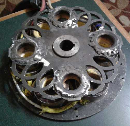 Having decided
to try welding the "salient poles" onto the
rotor (iron powder toroid cores matching the ones on the stator)
I figured I could at least get that done. I thought it went pretty well
until I discovered one of them was visibly crooked. It must have caught
and "hung up" somehow. I'd have to grind it off and try again.
Having decided
to try welding the "salient poles" onto the
rotor (iron powder toroid cores matching the ones on the stator)
I figured I could at least get that done. I thought it went pretty well
until I discovered one of them was visibly crooked. It must have caught
and "hung up" somehow. I'd have to grind it off and try again.
So I
might as well weld some "optical interrupter" bits or arcs of metal on
at the outer rim at the same time next time I get out the welder. So I
have to make those first.
In Passing
(Miscellaneous topics, editorial comments & opinionated rants)
America at the Crossroads: Restart
and Fresh Progress, or a New Dark Age?
I have for some time been
following the attempt to "drain the swamp" in the USA, on Youtube where
real journalists make their real investigative reports to the minority
who listen. [X22 Report, SGT Report, USA Watchdog, Dr. Dave Janda, and
many others do real political reporting in and on USA.]
In February 2017 (IIRC), president Trump announced that
corruption was a "strange and unusual threat" to the country, of such
monumental proportions that he declared it a national emergency. An
executive order was signed and further steps would be taken. (You
didn't hear this most monumental announcement by none other than the
President of the USA!?! Such is the level of corruption within the news
media establishment itself that they choose not to mention it, then or
any time since. But apparently the corrupt are all scared out of their
wits.)
In fact, steps to fix it were doubtless charted out well
before that. It's been said that Trump has the support of the military.
What may be closer to the truth is that some high-ups in the military
got fed up with fighting wars for the corrupt "status quo" on behalf of
the banks, big oil and arms merchants, and they resented Obama's purge
of their ranks. They recognized that the top villains were all in
cahoots, and were occupying all the high positions of economic and
political power sequentially, so that it was impossible for an outsider
to be elected to high office and reverse the trend. The highly paid
off, corrupt news media (virtually all owned by 6 or so persons and
under the direction of the CIA) paints these people in glowing terms
without reporting their heinous acts that make Watergate look like a
tiny blip, while trivializing and demonizing all their opponents. So
the public was mostly lulled to sleep and had - and still has - no idea
what was and is going on. (Dec. 2nd: a middle east fleet commander has
been "found dead in his residence", and days earlier a government
whistleblower's home was raided by the FBI in contravention of
whistleblower protection laws - are they getting rid of and
intimidating witnesses?)
How to end it all and save democracy? Rather than stage a
divisive military coup that would likely end in civil war and blood in
the streets, the military came up with a brilliant plan. They would get
an outsider elected, someone with no more love of these people than
they had, who could get the whole machinery of the nation behind
cleaning it up. They asked Trump, who had never been in politics, to
run for president. Some say he had more than their backing: he was
chosen by them and his running for president was their idea. I marveled
that he got the republican party nomination. When Ron Paul tried in
2008 he drew huge crowds like no one else and won many votes in the
first state primaries. The news media pretended he didn't exist. One
person came first, others came third and fourth. No one came second.
The extent of the insider racket was revealed when Jebb
Bush, losing in a debate to Trump in the 2016 primaries blatantly said,
"Yah, but I'm going to be president and you're not." It was revealed
again on election night, when the corrupt TV media personalities,
supposedly covering in a fair and unbiased manner a supposedly fair and
honest election, were visibly dismayed and almost distraught as Trump
won state after state. They wouldn't announce him as winning a state or
the election until there weren't enough votes left to swing it even if
they were all for Clinton. It was in fact supposed to be all scripted,
but somehow it just wasn't going according to the script! And these
"unbiased" presstitutes have unceasingly attacked their new president
ever since. To them he is just an arrogant oaf who acts solely out of
impulse and can do nothing right, who some "useless eater"
"deplorables" somehow put into the white house by mistake. What
they are most afraid of is real, rule of law justice.
Notwithstanding that enough people, sensing that all was
not as it was being painted out to be, voted for "egoist" outsider
Trump given the "queen of corruption" alternative, how did he ever get
into the position where he could be voted for? And how does he even get
the support of corrupt republicans in the senate? I now expect there
must have been much pressure put on various people behind the scenes,
probably by military figures and their supporters. No one gets to the
white house simply on merit, or achieves anything good while there,
without
powerful support! It's been half a century since anything much
favorable to the hardworking American people has been done by their
government.
But that's just background info. Back to the plot. When
Trump announced the national emergency, almost special 500
investigators were put onto the case to get the real scoop on all the
corruption - as well as the pedophelia and human trafficking that many
of the same people were involved in. They came up with over 60,000
indictments, which remain sealed until the time to make arrests comes.
Those are the people who were in complete control of America until the
unexpected election result and who
are now fighting Trump tooth and nail. At that time, all available
forces are to be called out to impose 72 hour martial law and make the
arrests. There's the reason Trump has been revamping "gitmo" and some
of the closed "for profit" jails. And at least the most treasonous top
people if not all of them are evidently to be tried by military
tribunal.
It is suspected by some that the time for the arrests was
supposed to have already come. There are so many judges in on the
corruption that no move was to be made until some were replaced, and
Kavanaugh was confirmed -
a majority who would convict the guilty in accordance with rule of law
was required on the supreme court. Digging up accusers from under
rotten logs who would perjure themselves to accuse Kavanaugh of rape at
the most opportune moment was another desperate ploy by the guilty.
They
hoped public opinion would convict Kavanaugh and force him to step
aside. If you were in a position to have to confirm appointment of a
judge who you expect will sentence you later for your crimes, wouldn't
you try anything to block his appointment?
With Kavanaugh's confirmation delay the arrests were thus
delayed until after the November midterm elections. Score one for the
corrupt "deep state!" The more they can delay, the more tricks they can
pull to try and weasel out of everything and get back in control. OTOH,
the republicans secured their hold on the senate in that election,
which plays into the hands of the plan. The house is needed to pass
bills, but the senate controls the judiciary. Bills aren't needed to
arrest and try people. The judiciary is. So perhaps Trump too decided
it would be best to wait until after - and not just to avoid it giving
the impression of interfering with the elections.
[per Dr. Janda interviewed on Silverdoctors, whose father
did construction contract work for Trump, but in my own words:] Trump
has built a number of very large buildings. If anything goes wrong in
one of those, it can be a complete disaster. He asks for all the
information, not just the bullet points, and he surrounds himself with
talented people who don't hesitate to disagree with him if they think
he has something wrong, and he asks many questions. He gathers all the
information he can get. His planning is thorough and methodical, and I
would presume no foundation is dug until every detail is ticked off as
ready.
Let us hope that is the case here as well. It sounds like
such a huge operation could hardly be in better hands.
Paying for caravans of migrants and criminals to come up
from Central America was another corrupt "deep state" tactic. They
hoped that the violent agitators among them - probably pushing the
women and children in front of them - would rush the border and force
the military to respond with violence, perhaps open fire on the crowd.
Those would make great video clips for the headline news! What an ogre
that Trump is, shooting innocent women and children! Maybe they could
get him impeached? Or they would be let through and Trump's policy
would be seen as a failure. The media would never let either story die.
Realizing what was doubtless intended, putting up barbed wire to
prevent people from rushing the border was a good response.
Having failed so far to murder him or disgrace him,
impeachment is definitely on their minds when the new "democrat" (it
hurts to have to use such a word to describe dictatorial oligarchs)
controlled house opens in January. Any excuse will do.
And therein is the crossroads. If the arrests aren't
carried out before the new year, Trump may be impeached and
escorted from the white house in disgrace and the whole plan will be
scrapped. If they can further delay the day of reckoning, they may put
it off forever. If that happens even the semblance of democracy will
soon be dropped. If they restart the wars they are still adamant about
in the middle east, the conflict can hardly escape becoming global. In
the next article below I speak of one of the current plans. A new dark
age will have descended, perhaps with very few people in it - or even
extinction of life. (If Clinton had been elected, we might well be
there
already.)
But postings by the obviously highly placed "Q" - who may
simply the codename mouthpiece for the military and Trump and perhaps
not even a single person - indicate that December 5th is going to be a
big date, and that "nothing can stop it." But is it the main event?
Probably not. It's probably the release of the unredacted documents of
illegal and treasonous dealings already demanded: the FISA warrants and
a couple of others. But it will be a big step in awakening the American
public to how underhanded the dealings of their elected and
appointed officials have been, and thus to helping to prepare them for
what is (hopefully) to come.
If the corrupt are all arrested en masse and thus "the
house is cleaned", "the swamp is drained", it doesn't solve all the
problems. Without advancing democratic governance to a more evolved
status, the swamp would gradually refill and be repopulated by new
swamp creatures, or even some of the same ones. And indeed economic
collapse, monetary collapse, plagues, famines, climate cataclysms and
Earth disasters complete with heavy population reductions are just
around the corner regardless. But at least for the time being, when and
as those strike, rational people will be at the helm instead of those
bringing senseless war, trying to micro-manage and control everyone,
and trying to
make life as miserable and unfulfilling as possible for everybody.
I have considerable confidence or at least high hope that
the cause will not fail and the light of freedom on Earth will
not be suffered to be extinguished for 1000 years. We will be granted
the time to evolve our systems to the point where ruthless dictators
won't have access to the halls of power, where social continuity,
social stability and finally social sustainability can take root and
flourish, never ever to be uprooted again.
How can we help in these monumental dealings over which
most of us have no influence or control? Pray for president Trump that
he isn't murdered, removed from office, or the plan is otherwise
derailed. These are critical times. Anyway there probably won't be much
longer to wait.
NO MORE WARS!
NO MORE VIOLENCE AGAINST SYRIA!
This is a special message to
certain members of the US/Washington DC "Deep State" and all others
involved just in case any may somehow chance across these words and be
moved to read them. You know who you are. As many Syrians displaced by
your years of ruthless bombing and proxy wars start to return home, and
the world starts to breathe a huge collective sigh of relief, I hope
and I pray that forces of peace, goodwill and sanity in America will
prevail over you.
But if you should manage to destroy Damascus and
mercilessly
slaughter people with a nuclear bomb - one and a half million
immediately and with millions more even into Iraq and perhaps Iran are
doomed to painful, lingering deaths - a collective insanity will surely
engulf America. It won't help to have your Israeli puppets carry out
the
actual deed - your evil designs are already known. Americans and the
world have put
up with a lot from you and your ilk for a long time, but you will have
crossed a vital threshold in the collective consciousness. Do not count
on the American public, or the rank and file in your many "security"
agencies
and your military to continue to take orders from you. Tens of millions
of
Americans will die in the ensuing confusion and chaos, and
a special vengeance will doubtless be extracted on those who are
thought to have had anything to do with the heinous act, and perhaps
on
their families, friends and associates. God Forbid... You May Not
Bomb Damascus!
Pause to consider Judas Iscariot. He was thrilled to
betray his fellows
imagining great rewards and honors, but after the deed, when he saw the
horror of what he himself had done no one had to bring him to
justice - in his utter disillusion and despair he killed himself.
Examine your motives and your prospects. Why are you
fighting to
restart a potentially globally suicidal war just to enable a gas
pipeline across Syria when the gas will soon no longer even be
wanted in Europe? How much longer
do you expect to delay the common utilization and commercialization of
free energy, known for many decades if not over a century and better
understood by more and more people each year in our new information
age? How much of your greed and ill will do you wish to have paraded on
public display at the expense of your own lives, your childrens'
lives... and your own immortal soul? How much more of Earth's natural
resources do you hope to squander today at the expense of your
grandchildren and all future generations? Peace and goodwill, or
widespread chaos, death and destruction in America, and personal
violent liquidations for yourselves one way or another - what do you
want?
The whole world is praying that either you change your minds or are
removed
from positions of influence. Think about it.
The
Exponential Function & Global Growth
20 Years ago the world looked rosy: Why are times
getting so tough so
fast?
I've mentioned overpopulation
before. If the population is low enough, isn't there plenty of land,
housing and food for everyone? Don't we all live like kings? But if the
population is double an "optimum level", then for only 1/4 of the
people to have optimum resources for a good life, they need half of
everything, leaving the other 75% with the other half - an average of
1/3 of the optimum per person. If it grew to triple the "optimum", the
figures get dramatically worse. And thus as population grows there is -
or will be, if one doesn't think there is now - fierce competition to
live well, damaging the core values of social sustainability: Equality,
Growth, Quality of Life, Empathy, Compassion and Love of Humanity...
and even Life itself for masses of people comes into in jeopardy.
I know there are a lot of people who presently don't think
the
world today is overpopulated, that our problems are strictly social and
political. Technology and new energy sources will solve everything. Al
Bartlett (1923-2013) was a University of Colorado (Boulder) physics
lecturer who
laid out the problems of continued uncontrolled growth on a finite
planet in terms
of simple arithmetic, with real world examples, starting decades ago.
Even if eight billion people isn't too many, the presenter shows us how
close to the brink we must be. How uncontrolled growth hurts us, how it
destroys democracy and cheapens the value of life - which causes the
social and political problems.
When I was young there were less than 3 billion people.
That figure was thought excessive by some - "How will we feed them
all?" If eight billion
people today isn't too many, and if then the population keeps doubling
every 40 years, will 16 billion be too many? Many now living will still
be here then. In 80 years, will 32
billion be too many? How about 256 billion in 200 years? or 8.192
trillion in 400 - a thousand people for every person today? How many
before we are all standing shoulder to shoulder everywhere? At just
what level would you expect "the population bubble" to collapse?
The video I watched
on Youtube was called:
Arithmetic,
Population and Energy - a talk by Al Bartlett
(Search for it.) Bartlett lectured on these topics over 1600 times,
almost to age 90, and a number of videos are available.
This lecture was in 2002. Perhaps somewhat prophetically for that time
he mentioned that he thought
that global warming would become the biggest threat. Bizarre
weather and climate catastrophes certainly are becoming huge problems
for life and food production today, with globally severe crop losses
this year and apparently worse to come. And this in spite of the
overall increase in heat (especially in the arctic per TE News #109 -
the cold temperate winters in some areas are also a result) being
somewhat mitigated by the developing solar minimum (a slight reduction
in
the sun's output over a span of years or decades).
And there are many other
insights in this 75 minute video that illuminate and throw a broader
perspective around the problems we are having - and how the less people
knew and the less they examined the problems (2002 - especially
officials and 'experts'), the more confident they were - and many still
are - that all problems could somehow be overcome... without limiting
population growth.
But here is a related thought: When populations get too
crowded, diseases strike. That doesn't only apply to human populations.
When interior BC forests were logged and replanted with pine trees
everywhere (known in farming as "crop monoculture") a normally minor
pest, the pine beetle, became a huge epidemic and killed them en-masse,
province-wide.
And once upon a time, potatoes were brought from the
Americas to Europe. They were planted everywhere, especially in Ireland
where they grew well. With such dense populations of potatoes, a great
new food source, the human population grew, but when a potato blight
struck it quickly spread everywhere. This caused the "Irish Potato
Famine". Over several years millions starved and many millions more
emigrated to find food. (Perhaps they were modern history's first mass
economic migrants?)
Today to support humanity's many billions, food crops
cover nearly all the planet's arable land. (And today's farming
techniques aren't sustainable to start with.) Wheat fields cover the
Canadian prairies, and corn farther south in the USA. Is it not
possible, even inevitable, that such huge crop monocultures will be hit
with a plague or plagues, such as some new strain of "rust" to which
the wheat isn't immune, and it will quickly spread over the all those
connected fields to everywhere? As in Ireland but on a continental or
even global scale, devastation of vital wheat, corn, rice or other
major "everywhere" crops will not allow the present much increased
human population levels to be supported. As with Selkirk wheat, new
strains resistant to the new rust will be found or developed, but today
a gap of several years in commercial production will pose a severe
problem on top of all our other serious problems.
To underscore the above written earlier, on the 22nd I saw
a Youtube video by "Ice Age Farmer" showing an agro-insurance website
where the title was "Ontario Farmers Facing 'Catastrophic' Disease
Outbreak in Feed Corn". "DON"(?) mycotoxin had ruined 50% of the crop.
This was mentioned among all the other serious to severe global crop
losses.
And a dense urban, hungry populace is one itself
susceptible to epidemics. On the same evening (22nd) a "Full Spectrum
Survival" news video detailed at least three serious diseases, one of
which, Prion Disease, especially might be unstoppable if it gets going.
(also mentioned: Ebola is spreading in DR Congo; and H1N1 Swine flu: it
kills the healthy as much as the weakened.)
All these plus climate and geologic cataclysms will reduce
the present crowded human population to a much smaller figure in the
next two or three decades. Then the term "population management" will
become well known and much studied globally for the first time.
 Those in the East of North America might
perhaps be excused for thinking in the winter that
Those in the East of North America might
perhaps be excused for thinking in the winter that
"global warming" must be a myth and that in fact a "mini ice age" is
coming with the solar minimum.
Chaotic as the climate has become, globally there are more "above
average" temperatures than
"below average", and recent summers have broken many high temperature
records in many lands.
"Proportional
Representation" and the Third Stage of Democracy
The first place I heard of the present British
Columbia (BC), Canada provincial referendum on proportional
representation was Google ads saying how "great" our present electoral
system is, how it "works so well" and how terrible things will happen
to us if we change it, from which there would be "no going back". How
on Earth could any group with the money and organization to launch an
ad campaign be so convinced that the present unfair system that
generates so much political and social polarization and trouble works
well?, and why would anyone think that if we didn't like something, we
would somehow be stuck with it forever?
But that would seem to be the very situation we have now,
stuck with an unfair voting system where somehow all attempts at
progress and change have been thwarted for a century! (...like the
present federal government's solemn promise for electoral reform during
the last election, that was dropped once they won it, with some public
meetings about it apparently just to fool the public into thinking
things were moving forward for a while and to dilute and wear down the
critics. Justin Trudeau, unlike his father Pierre Elliot Trudeau, is
proving to be just another "deep state" puppet with no will to lead of
his own.)
Yet apparently only 3 democracies still use the
rudimentary and inherently biased toward polarization "first past the
post" voting system: Canada, United Kingdom and United States.
To me the "attack ads" reeked of well funded hypocrisy by
vested
interests who gain something from the present unfair system: the
behind-the-scenes hand of the rich and powerful trying to prevent
democracy from working and evolving, here by trying to manipulate the
public's opinions through misrepresentation and fear.
Later I found out that the opposition did indeed consist
of some of the very few richest and most powerful figures around BC.
Names of the individuals were given. They had tried first to prevent
the government from holding the referendum at all by trumped-up court
challenges. These failed. So now they have been trying instead to make
the BC public afraid to vote for any change. Will it work? Are there so
many "sheeple" to be herded back into the pen by the command of their
rich "overlords"? We shall see. (If the referendum passes, will there
be threats or inducements to the premier and individuals in the
government to "forget about it" without enacting it?)
I admire that the BC government is holding this referendum
which they apparently will enact if it passes, and equally how they
framed it. Commonly the several options would be presented - there are
many opinions on what would be most preferable - and one of the options
would be to keep things the way they are. Mark an "X"! This is the same
way "first past the post" elections are presently run. Since the
various options would "split the vote" of the majority who wanted
change, the substantial minority who were afraid of change and were
unwilling to open their minds and think about it or choose between
systems - and the tiny minority who think they benefit from the way
things work now - would win. The more options for change that were
presented the more certain it would be that the largest minority of
votes would be the one for "no change".
Instead, it was split into two questions. The first one
is: Do you want a proportional representation system:
yes or no? This question uses the present "first past the post", "mark
an 'X'" question that has to pass - but here it is fair as there are
only two options.
Then the second question is: What kind of
proportional representation system do you want? For that the
government gave three voting system options. Since the second question
only matters if people asked for change, they were free to pose it as a
more advanced Choice Ranking ballot. Instead of just marking
the "illiterate's 'X'" for one "first past the post" choice, voters
rank them 1, 2, 3 - 1st, 2nd and 3rd choice. If one choice doesn't have
over 50% of the vote, the votes for the least popular choice will be
"transferred" to those voters' second choice. Thus the winning choice
will have been approved by over 50% of the voters - no more minority
choice wins; no more can the less popular choices on a ballot
(whichever ones they prove to be) tilt the final balance in favor of
one or the other of the most popular.
Third Stage Democracy
It's great that the premier and the government has decided
to hold this referendum. But it is still top down - authoritarian. It
has been brought to the people by their government representatives.
If citizens had a venue for getting together and thrashing
out political ideas at a grass roots level, we would long since have
addressed this issue and come out with a consensus for a better system
- probably better than any of the present proposals. Since it would
have come from the whole public-at-large as a single recommendation, it
would have been passed by the government - or by the next government
that replaced the one that was unwilling to do the public's will. Now
that we have the internet, such a social sustainability design team
mechanism can come into play in the coming years. At some point such
local teams will surely "go viral" as the expression goes.
When they do, we will be able to start tackling all sorts
of issues that can't be dealt with by the top-down approach. Presently
local and community issues are subject to national regulations and
national decisions from the national leader. Since the national leader
doesn't have time to be informed about and deal with local issues all
across a nation, they simply are left in limbo. When instead decisions
are made at the local level and only feed up to the level that's
warranted, they can be appropriately dealt with.
More
California Fire Oddities
One clear thing emerges from the California fires: that
much of California is not only even more bone dry than usual, but that
it's littered everywhere with kindling to spread any fire out of
control, however it starts. especially in high wind conditions. But was
this in fact planned in advance, premeditated?
I understand that in 2016, with a major wildfire actually burning,
California state legislators passed a bill to help to get some of the
tinder dry chaparral & brush areas cleared off and make fire breaks
to limit damage that might be caused by future fires. It passed both
houses unanimously. Governor Jerry Brown vetoed it. This is the same
person who probably also ordered a truckload of petitions to be "lost"
so there weren't enough of them left to cause an [anti compulsory
vaccination?] initiative to be put to a public vote.
How does he get away with these things? Who is he working
for and are the elections that keep binging him back rigged?
People have noted that a "typical" house fire is about
1100°F. But metals that require much hotter temperatures have
melted in recent California house fires. There seems to be remarkably
little left.
 Unusualities: a house 3/4 demolished and the
other 1/4 almost intact?
Unusualities: a house 3/4 demolished and the
other 1/4 almost intact?
 and a truck, apparently bizarrely burned and
the steel door melted?
and a truck, apparently bizarrely burned and
the steel door melted?
(hmm... the whole picture seems rather bizarre)
Oh well, those who get out of California now may be the
lucky ones. There are predictions that large parts of Alaska and
California will sink into the sea in the upcoming years, Alaska first.
The BC coast will suffer too, but not so drastically except in the
north near Alaska. But with all the earth movements and rising sea
levels there should be plenty of nasty tsunamis and inundations for
everyone along the whole Pacific rim and islands.
Qualifying
to
Run
for
Office
A new American
congresswoman, Occasio-Cortez(SP?) was asked "What are the three
branches of government?" and she couldn't answer it. This must be a new
low in American politics. It underscores my idea that one should have
to pass some basic tests to qualify to be able to vote, and a bit more
in depth to qualify to run for office. I have no doubt that
Occasio-Cortez would be capable of passing the tests with a bit of
study, but no one should be in government while ignorant of most its
basic structures. We aren't even allowed to drive without studying up
on and learning the basic rules; why should we allow people to drive
the country without the same sort of preparation? (Hmm... the CIA, the
FBI and the IRS? ...or are those three "tentacles" of government rather
than "branches"?)
CIA: Rogue
from Day One
Quoted from a "Zerohedge.com" story Dec. 1:
>--- [begin quote]
One month to the day after President Kennedy's assassination, the
Washington Post published an article by former president Harry Truman.
"I think it has become necessary to take another
look at the purpose and operations of our Central Intelligence
Agency, CIA. At least, I would like to submit here the
original reason why I thought it necessary to organize this Agency
during my Administration, what I expected it to do and how it was to
operate as an arm of the President."
Truman had envisioned the CIA as an impartial information and
intelligence collector from "every available source."
"But their collective information reached the
President all too frequently in conflicting conclusions. At times, the
intelligence reports tended to be slanted to conform to established
positions of a given department. This becomes confusing and
what's worse, such intelligence is of little use to a
President in reaching the right decisions.
"Therefore, I decided to set up a special
organization charged with the collection of all intelligence reports
from every available source, and to have those reports reach me as
President without department "treatment" or interpretations.
"I wanted and needed the information in its "natural
raw" state and in as comprehensive a volume as it was practical for me
to make full use of it. But the most important thing about this move
was to guard against the chance of intelligence being used to influence
or to lead the President into unwise decisions, and I
thought it was necessary that the President do his own thinking and
evaluating."
Truman found, to his dismay, that the CIA had ranged far afield.
"For some time I have been disturbed by the way
CIA has been diverted from its original assignment. It has become an
operational and at times a policy-making arm of the Government. This
has led to trouble and may have compounded our difficulties in several
explosive areas.
"I never had any thought that when I set up the CIA
that it would be injected into peacetime cloak and dagger operations.
Some of the complications and embarrassment I think we have experienced
are in part attributable to the fact that this quiet intelligence arm
of the President has been so removed from its intended role that it is
being interpreted as a symbol of sinister and mysterious foreign
intrigue - and a subject for cold war enemy propaganda."
The CIA lies with astonishing proficiency. It has made an art form of
'plausible deniability.' Like glimpsing an octopus in
murky waters, you know it's there, but it shoots enough black
ink to obscure its movements. Murk and black ink make it impossible for
anyone on the outside to determine exactly what it does or has done.
Insiders, even the director, are often kept in the dark.
--->[end quote]
Why is it that time after time, presidents and other
public figures only realize or acknowledge the damage they've done
after they no longer have any power to influence events or undo what
they've done? And the
present occupier of the position never takes action to correct the
problem either?
Coffee Roasting
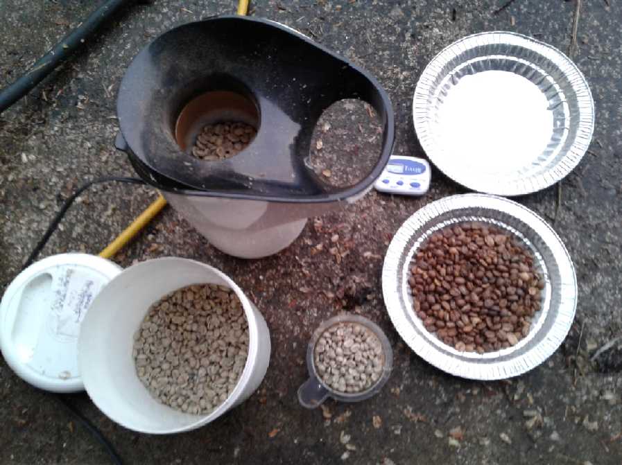 Coffee Roasting
Perhaps some may be interested? It's simple to roast
coffee. I buy "green" (raw,
unroasted) coffee beans in bulk (at GreenBeanery.ca), and roast them as
needed in a hot air popcorn popper. I like a pretty light roast, and
it's hard to buy that anywhere. I keep the green beans in a cool place.
They keep for ages - I haven't bought any in almost two years and
they're still fine. And it's cheaper than buying good coffee in a
grocery.
Required:
* Coffee. My favorite is "Nicaraguan SHG Fair Trade Organic". "Coffee
connoisseurs" have remarked what good coffee it is and where do I get
it?
* Popcorn popper (I don't use the lid) - the beans "crack" as they
roast
but they don't pop out. (For light roast, only a little "cracking". But
if it's too light it's hard to grind.
* Coffee container, measuring scoop.
* Minute timer unless you want to stand there and watch (time varies by
popper from 2 minutes to 8 and gradually gets shorter for some reason.
Since I started (10 years?) I've gone through 3 or 4 poppers.)
* Things to dump the coffee into. It's hot, and it smokes during and
after roasting, so it's usually done outdoors.
ESD
What is ESD? Eccentric Silliness Disorder
What causes ESD? Electrostatic Discharge while having Egg
Salad Dinner
When does it strike? Every Second Day during Easter,
September and December
Where does ESD strike? in Europe, Spain and Denmark, with
very isolated cases on Europa, Saturn and Deimos
For more information on ESD,
contact your local government branch of the Egregious Sarcasm Department
---
I Pulled a can of evaporated milk out of the fridge, and dropped it. I
grabbed it almost as soon as it hit the floor, but I turned it upright
the wrong way so it was upside down and still spilling. (the usual
result of a 50-50 chance) Dam, dam, dam dam! Is there any use cursing
over spilled milk?
---
Notice: Owing to changes in regional politics and weather
patterns, the name "Saudi Arabia" is henceforth changed to "Soggy
Arabia". (Can camels swim?)
---
Did you know?: Chordless phones can only play one note at a time.
"in depth reports" for
each project are below. I hope they may be useful to anyone who wants
to get into a similar project, to glean ideas for how something
might be done, as well as things that might have been tried or thought
of... and even of how not to do something - why it didn't
work or proved impractical. Sometimes they set out inventive thoughts
almost as they occur - and are the actual organization and elaboration
in writing of those thoughts. They are thus partly a diary and are not
extensively proof-read for literary perfection and consistency before
publication. I hope they add to the body of wisdom for other
researchers and developers to help them find more productive paths and
avoid potential pitfalls.
Electric
Transport
Reluctance Motor
While the "piece of pie" shape is probably the best for an axial flux
reluctance motor's coils and salient poles, at least the iron powder
toroid version which is presently easiest for me to make gives the
effect (and better) of steel laminations
versus my only "homebrew" alternative, solid steel chunks.
I thought I was going to make a table for my electronics
lab before resuming this project. But there were things to do before
setting motor and controller up on a bench, and I was sorry this
project was falling behind any sort of schedule.
I decided to
weld the "salient pole" toroids directly to
the rotor plate - assuming that would work. It would solve a lot of
confusion about how best to do it, while actually being best. But since
I don't really know how they're made, it might not work. They kind of
look like they're made of sintered together iron particles, but then
again they might be glued together with epoxy.
On the 25th I put them on the lathe and
turned/scraped/filed off the epoxy outside coating. Now there was bare
metal (if such it was) to weld to. Magnetically the tops should be
flush with the top of the rotor, but I'll have them stick up a little
to be sure they can be solidly welded into place even if things aren't
perfect. (My welding is much less than perfect at best!) I wasn't going
to weld indoors, so what I needed next was a nice day. Those were
getting rare near the end of November. I was already waiting for one to
resume lumber milling. But one finally came along and I did the
welding. Unfortunately one is crooked and will have to be ground off
and redone.
The rotor would have to be
raised up by the amount the
toroids stuck down, and I figured out what to do about that: I would
put another "weld-on hub" the same size but with a slightly larger
center hole onto the bottom plate of the motor. (I even have it!) I'll
turn it on the lathe to get the exact height and fit for the bottom of
the 70 mm thrust bearing. The outer needle bearing can stay in its
original place.
I could still use the sameunipolar motor controller.
I had it all figured out... oh, wait... I have to make some new optical
interrupter, four slots and four solids around the outside rim somehow.
But soon I had a plan for that too. It involved some more welding and a
bit of grinding. Oh, and new mountings for the optical interrupters.
And once it's turning, a new outside rim and top.
Other "Green"
Electric Equipment Projects
Carmichael
Mill ("Bandsaw Alaska Mill")
Sawing up a cant of wood (6" x 1.5" boards x
12') Nov. 7
As I said last month, I had taken footage to make a video
about the bandmill. I made it and here is the link:
https://www.youtube.com/watch?v=P7r6hQF3yg8
The mill was cutting well
with remarkably little trouble. But somehow the blade always seemed to
have trouble cutting the last board or two off a cant. I cut one large
one on the 7th and 8th, getting
nine 12 foot 2"x6"s and one 8 foot from it. Again it seemed the band
was dull by the last couple, and they were hard going. Well, the band
had cut over 50 square feet of surfaces. Perhaps that's as good as it
gets?
But I figured that cutting at the bottom, as there was
less "cant" remaining in some sections than the material in the board
being cut off, the remainder under the board often wasn't very stiff
and was bending and closing up the cut. Perhaps that was why it always
seemed dull by the time it was at the bottom? However, putting wedges
in the cut behind the saw only seemed to be a partial solution.
This time (11th - being out of new bands anyway) I decided
to try using the same seemingly dull one to start the next cant. It
went okay if a bit slowly. But by the time I finished there seemed to
be some vibration. I started on the second board but it was getting
worse. At first I thought it must be the bearing in the saw. Then I
discovered that the bolt holding the pulley on was loose. But
tightening it didn't help. I took the saw inside and found the bolt was
again or still loose. Again tightening it didn't help. Perhaps it came
loose again because of the vibration rather than being the cause of it.
Motor Madness
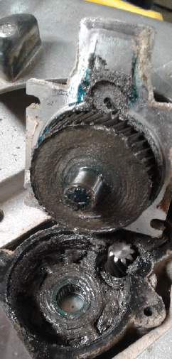 The spindle of the saw
came off with four bolts, and I saw that a
small gear on the motor turned a large one for the blade. I thought it
was probably the gears. They looked fine to me, although there didn't
seem to
be any grease left on the teeth. I ran the saw motor without the
spindle and
it seemed smooth. Apparently with some kind of mental disconnect, I
took the smoothly running motor apart. I couldn't get the bearing off
that end by pounding on it, but I did somehow make it not turn
smoothly. Something seemed to be hitting something five times per
rotation. The plastic fan had five "spokes" on the side I could see,
and a sheet metal plate wasn't sitting quite flat. Probably it was
hitting five more spokes on the other side.
The spindle of the saw
came off with four bolts, and I saw that a
small gear on the motor turned a large one for the blade. I thought it
was probably the gears. They looked fine to me, although there didn't
seem to
be any grease left on the teeth. I ran the saw motor without the
spindle and
it seemed smooth. Apparently with some kind of mental disconnect, I
took the smoothly running motor apart. I couldn't get the bearing off
that end by pounding on it, but I did somehow make it not turn
smoothly. Something seemed to be hitting something five times per
rotation. The plastic fan had five "spokes" on the side I could see,
and a sheet metal plate wasn't sitting quite flat. Probably it was
hitting five more spokes on the other side.
Then I inserted a screwdriver through the fan blades and
tried to pound out what I thought would be a sealed bearing that held
the spindle. I succeeded in punching a hole in the piece of metal, and
then pushing an integrated needle bearing race out a bit. The needle
race was a separate piece, and it seemed all it needed to get it out
was some little hook under it.
The motor didn't seem to need to be apart so I put it back
together except for the spindle and ran it again. It was as always so
noisy
anyway I couldn't even hear if there was any extra clicking from the
spokes. (And since I didn't have the gear connected, apparently all
that noise was just from the brushes and the fan.)
Getting a hook under the bearing race didn't work. But the
bearings on the spindle seemed smooth enough... I put the spindle back
on, and it seemed to run just as rough as before. Finally I took the
spindle inside and looked at the gear through a strong magnifying
glass. There, it did become obvious it was quite worn. The gear teeth
were pitted and worn to a pointed shape at the outside on the driven
face. All that hard milling, plus (seemingly) no grease. If I continued
the teeth would surely fail completely, probably destroying the gear on
the motor as well.
So once again, milling came to a halt to await parts for
the mill. True, milling could go faster if the mill had a little more
power, but the idea of changing everything that had been working so
well and putting my Electric Caik motor on just wasn't very appealing.
Doubtless I could order a whole new saw. Could I order just the gear or
spindle or output shaft assembly?
The next morning I decided
to give up on the idea of
fixing the saw. If I found the part and replaced the one gear, there
was no guarantee the other wasn't too worn as well. I've tried fixing
angle grinders with worn or broken gears. It's usually not worth it. I
went on line to Home Depot and as I hoped I found the 13 amp Ryobi saw
for 60$. But I also found a 15 amp Ryobi saw for 90$. One wouldn't
think there'd be much difference, but a neighbor had said 15 amps would
be better - and there it was: "a little more power". A very little bit
more; 15%. But if it would make milling go even 10% faster, or make an
extra inch width easier to cut, would it not be worth it? So I went for
the extra.
At the same time, I had been thinking for a long time that it would be
nice to have a handheld power planer. The thickness planer was great as
long as the boards were under 12.5" wide. A wider slab can't be done at
all, nor with the 6" jointer. There was a Bosch planer with "reversible
micrograin carbide blades" for "a mere" 170$. and extra blades for 25$.
It also had adjustable guides on the side. So with a straight edged
guide one could plane a wide slab, doing one straight 3.25" row at a
time. (Well, hopefully that would work - I've never used a handheld
planer before or seen whether the edges of the joins would dovetail
smoothly.)
They sent them UPS! I figured I'd have them before
Christmas. When I mentioned the problem to someone he gave me an old
Mikita skillsaw with no brushes and a bent blade guard.
But actually the new saw (only the saw) soon arrived. I
did other things until the 26th. That day (finally) was nice out, so I
drilled a couple of bolt holes and mounted the new Ryobi. The next
problem immediately reared its head: I had no more sharp bands. I cut
into the 16' cant and it didn't go well at all. I changed to another
band that looked better. But it was nothing like new. I eventually got
to the end with a lot of zig-zagging and the band heating up. It was a
nice but hard won 1" x 8" x 16' board. I wasn't about to try for
another one. Whether the 15 amp motor was better than 13 amps I
couldn't tell.
I wanted to see if the old Ryobi brushes would fit in the
(13
amp) Makita. It would be nice to get a skillsaw out of all this! But I
didn't find the time.
 To set this 24"x8"x16' cant on edge I had to
use a big "jackall" jack
To set this 24"x8"x16' cant on edge I had to
use a big "jackall" jack
 When a band gets dull enough, sawdust sticks
to the teeth.
When a band gets dull enough, sawdust sticks
to the teeth.
 I eventually got to the end of the board.
After that one, I got the band sharpener working, first
try not the best, second try not so bad (but can probably be improved).
Bonus Tip: Someone told me that firewood stacked against a
tree would stay relatively dry, because the rain tends to drip down at
the outside of the branches, not near the trunk. My firewood shed being
full, I decided to try it out.

Handheld Bandmill Troubleshooting Guide
I figure if there are going to be saws or kits for sale, it needs a
troubleshooting guide, so here is the start of it:
Band comes off the Wheels:
* Wheel alignment is off
* Band tension is too low
* Sawdust buildup on band or wheels (This is why the wheels are now
slick
UHMW!)
Band slips:
* Band tension is too low
Saw is jammed in the cut:
* Back it up 1/8". The teeth get stuck in wood at the end of the cut.
* Put in a wedge(s). The wood could be closing up on the kerf.
* The cut has gone off line and may be "bowed" inside the board,
owing to a dull band, insufficient band tension, tilting the saw while
cutting, lifting of the back end of the saw, or wood irregularities
(esp. knots). Back it off several inches or until
a position where it turns freely.
* At or very near the end of the cut, the top board can drop down onto
the
band. If the teeth are visible across the end, it may be possible to
pull the saw out or to pull the board back away from the saw.
Otherwise, a wedge or two in the cut behind the saw may be needed.
(Putting wedges in before reaching the end of the cut can help it
finish smoothly.)
The board(s) have bend(s) in the cut at the point where a wedge is
being inserted:
* Don't wedge the cut open too wide.
Band Gets Dull Fast
* Steel band teeth don't stay sharp as long as carbide saw blade teeth
- Relatively frequent band changing and sharpening is a normal part of
steel tooth bandsaw milling. Expect to make under 100
square feet of cut surfaces before changing or sharpening the band,
depending on species being cut and other factors such as where it was
grown. An automatic band sharpener is recommended if there is a lot
milling to be done. There are plans for homemade sharpening jigs on
Youtube etc.
* Cooling water has run out during a cut or is not flowing fast enough
to keep blade cool. The sponge in the water system gets clogged and the
sawdust, etc, needs to be occasionally squeezed out. Badly overheated
blades may dull almost immediately even if resharpened, if the
tempering/hardening has been lost from the tooth tips owing to heat.
(This also applies to overheating the tips during sharpening, as with
using a
"dremmel" tool running at a high speed.)
* Minerals or sand in bark and or wood. It is best with some species,
or trees grown in some locations (eg, near a sandy beach in a windy
area) to remove the bark before cutting. My method is to use a flat
blade shovel, with the end sharpened on a grinder. Hammer and chisel
has also been used. Debarking may be easier if the tree has been down a
while.
* Nails, lag screws or other metal pieces in the wood. This happens
mostly but not exclusively with trees near houses, where they may get
clotheslines attached, be used as a fencepost or children may drive
nails into them for fun. Later the pieces are forgotten and the tree
grows
around them. (I've even seen pieces of clothesline wire complete with
the pulley,
and electrical wires, completely grown into a tree or large limb.) If
suspicious, a metal detector or rare earth supermagnet may be tried to
detect them, but in my experience results are not usually certain.
Rough Running
* You're cutting into metal?
* Tracking is off.
* Pulley on saw motor is loose.
* Something else is loose or a bearing is bad.
* Gear teeth inside spindle of motor are worn out. Motor needs
replacement or repair. (Preferably, occasionally open the four screws
and grease
it inside while they're still good.)
* Brushes on motor are worn out. (Congratulations on having done so
many hours of milling!)
Recycling
Scrap HDPE (or UHMW or PP?) Into Useful (millable) Shapes
In my youtube wanderings I found a video, How to
Recycle HDPE Plastic (High Density Polyethylene) - a simple method,
which
relates
to
my
putting PP (Polypropylene) rope in a pot and
melting it down into a block of PP last January (TE News #116). This
person got a bit more clever and used a sandwich toaster and colored HD
polyethylene food containers to make flat sheets or blocks of plastic.
He had a figure for best temperature to soften and mix HDPE pieces:
about 180°C or 350°F. I expect it could be done in an oven
using a few flat metal plate clamping pieces and C-clamps, too. I hope
it can be done without cutting them up into such tiny bits as he did!
(I think part of his aim was to get the kaleidoscope of decorative
colors.)
I've cut thick, flat pieces of UHMW polyethylene using a
CNC router to make molds for motor parts, etc, per various TE News
issues mostly around 2010 to 2012. (How about bandmill wheels?) A "one
board foot" (12" x 12" x 1") piece of UHMW cost around 40$ at a store
in Victoria, so to make it oneself from scraps seems like an attractive
proposition. Perhaps to stick with UHMW one could use small and large
scraps of that (and I saved some milling shavings perhaps for this sort
of purpose... if I can find them). Or perhaps HDPE would work fine for
epoxy molds too.
Obviously from the video it works well with HD-PE.
(Presumably UHMW-PE would be similar.) I've previously softened and
bent ABS and PVC plastic pieces in the oven at 250°F. Whether or
not this "sort of" melting down at 350°F would work with PP would
be interesting to try. But if it needs a higher temperature and smokes
like my "melting down PP in a pot" experiment, I wouldn't want to do it
in the kitchen.
Who needs to Have a Kitchen Stove?
On an almost unrelated note, I went into the Home Hardware
store in Masset looking for a new coffee maker, and in looking around I
found a flat-top "inductive heating" hotplate, and an "air cooker". The
inductive hotplate could be temperature controlled, and it might be
used for melting the plastic--? But I bought it
because it had a timer and could be told to shut itself off (eg, after
the rice was done, while I was outside doing something else) whereas
stove burners will continue to fry it to a crisp and a house full of
smoke, and I wondered why I had recently purchased a new kitchen stove.
Two hotplates would be two burners (one more than I usually use), the
air cooker sounded better than an oven, and the total price for all
three was less than 1/2 the price of the stove. In addition,
potentially a burner/hotplate (or even both) could be put away to free
up counter space.
If you set the hotplate on the stove... well, just don't!
When you accidentally turn a burner on underneath it instead of the
hotplate the bottom plastic melts and smells terrible. and might start
a fire. (I think that's the only time I've used a stove burner since I
got the hotplate.)
Wind:
VAWT Studies
In looking at all
the VAWTs on youtube, there are lots of very different designs and they
all seem to turn. One interesting video titled vertikalis
Winrad RH2015-01, vertical axis windturbine, Germany had "V"
shaped blades. The pointy end cut through the wind going into it, while
the broad open end would catch it on the way downwind.
But which design, or which style of designs, can output
the most power from a given wind? This was the part that was
frustrating. Surely there had to be a known optimum shape of vanes and
density of vanes? Or at least, surely there must be some way to compare
them?
I decided to look for something outside of Youtube and
found a study by several Worcester Polytechnic Institute students in
pursuance of their Bachelor of Science degrees, from 2013: Vertical
Axis Wind Turbine Evaluation and Design. After plowing through all
the background information (AKA academic "mumbo jumbo") I selected the
following interesting information - partly from their results but more
from their conclusions. In their Results:
1. The Split Savonius Rotor (two half barrels, slightly overlapping)
performed a little better than a four blade airfoil design.
2. Either unit performed much better with a shroud blocking the wind
from the unwanted direction or shifting its direction. RPMs went up as
much as 65%.
3. The best shroud design very much depended on the type of turbine it
was shrouding.
4. Their small units didn't make much power. Nowhere did they get even
1/4 of a watt. Their generator was doubtless less efficient than my
Improved Piggott one (oversize tho it is for this featherweight
application), and had cogging that prevented turning with light forces.
It was hard to judge the forces because they used a wind tunnel with
wind speed measured in "hertz", which was nowhere explained for
conversion to understandable units.
In their Conclusions (which also included considered speculations):
1. The better performance of the Savonius "split barrel" design was
attributed to the large surface area of the vanes catching the most
wind.
 2. The semicircular barrel
shape would probably be better with a "V" on
the outside to deflect wind when traveling upwind. I was surprised to
see this, so soon after watching the German VAWT video with that very
shape of vanes. (I don't suppose the shape of the wide end matters very
much, so the simple "V" might be just as good as the Savonius "half
barrel" with a "V" on the outside.
2. The semicircular barrel
shape would probably be better with a "V" on
the outside to deflect wind when traveling upwind. I was surprised to
see this, so soon after watching the German VAWT video with that very
shape of vanes. (I don't suppose the shape of the wide end matters very
much, so the simple "V" might be just as good as the Savonius "half
barrel" with a "V" on the outside.
 3. The "Reverse Funnel" concept. A funnel
trying to push air into the
side of the unit moving downwind to increase the velocity didn't seem
to work very well. But they noted that Japanese (and earlier)
researchers used a "reverse funnel" in tidal power units to create a
low pressure region that would increase water flow. They drew a
two-dimensional
version of that should pull more air in.
3. The "Reverse Funnel" concept. A funnel
trying to push air into the
side of the unit moving downwind to increase the velocity didn't seem
to work very well. But they noted that Japanese (and earlier)
researchers used a "reverse funnel" in tidal power units to create a
low pressure region that would increase water flow. They drew a
two-dimensional
version of that should pull more air in.
The students concluded that they hoped their work might help future
research. Thank you!
I noted the reverse funnel concept last month, and that an
"outside rounded" entry side also helped the flow. But I still think
the full venturi form with larger entrance as well as larger exit would
be optimum - assuming one is going to go to the trouble of building
such forms around the outside of the rotor. The low pressure caused by
the exit funnel will cause the air to suck into the entrance funnel for
maximum effect. To be applicable to shifting winds, it would have to
rotate to face the wind. But then one should get the performance of a
unit with a much larger rotor than it actually has.
That's really pretty similar to the tide power ideas.
A conclusion of mine - for "Savonius Vanes" rather than
"propeller" or Darius "Airfoils" - It's basically the wind pushing on
"X" amount of surface moving away from the wind, below the wind's
speed, that determines the available power. Subtract from that the wind
force trying to slow down the other side of the rotor that's coming
back upwind.
Considering that, the most important features are the
surface area catching the wind while going downwind, and the
effectiveness either of the shrouding or of the vanes to shed the wind
going back upwind. Going downwind, the vane's shape is much less
important than its effective area, provided it doesn't "spill" much
wind. Going upwind, for fixed vanes, I think the point of the "V" cross
section seems like the best shape to spill the wind. And the broad end
of the "V" isn't going to spill much wind going downwind, so it's
probably the best overall profile.
I'm also wondering (again/still) about pivoting vanes. In
this case, if the inside of the "V" was free to flap closed against the
outside, it would snap closed when it pointed straight into the wind
toward the end of the downwind leg, and turn the vane from a "V" into
an angled flat vane ("/") going around the downwind side. After a short
segment of mild reverse thrust (depending how wide the angle of the "V"
was - at 90° or wider there would be none), this would be angled to
push wind and then have actual lift to propel it through more of the
rotation, then it would point straight downwind to cut in half the
upwind leg drag. As it came toward the upwind side, it would gradually
open, and assume the "V" shape again for the push from front to back
again.
A bonus feature is that if the unit was spinning too fast,
the "V" would be pressed against the outside by centrifugal force and
wouldn't open readily, reducing power.
So there are two similar concepts and one rather mutually
exclusive that might perhaps be profitably explored:
1. A rotor with "V" vanes might be the most effective simple fixed vane
'Savonius' VAWT. Whether this would optimally be vanes on the outside
of "spokes" or big vanes in the overlapping Savonius configuration
might have to be tried to find out.
2. A rotor with inside-face folding "V" vanes (on spokes...?) should be
still more effective, and partly or even largely eliminate the value of
an outside shroud.
3. An outside shroud that forms some sort of venturi, shaped to feed
and to extract air from the proper sides of the turbine, with "funnels"
as in the Worcester drawing above, but both in front of and behind the
turbine. Does it matter that "Savonius" rotor speed is less than wind
speed if the venturi has accelerated that speed 2 or 3 times where it
hits the vanes?
Of course this adds a big cumbersome structure which would
have to rotate to orient to the wind direction, but the power is taken
from the wind across that whole structure instead of just from the size
of half the spinning turbine, so the potential power is as great as
that of a a much larger simple rotor.
If one has gone that far, the rotor might as well be
entirely enclosed in the venturi housing. (with screens to keep bug and
birds out?) And then, might a Tesla Turbine (see TE News #106, Nov.
2016) not be better inside the arrangement than a turbine with vanes?
We see here that we have moved completely away from the simple savonius
VAWT to some much more sophisticated type of wind power system.
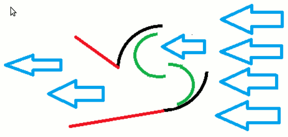
 Optimized entry and exit funnels of the venturi would
probably not be the same size and profile. If the design could be made
to swirl the air inside in the direction of rotation on its way
through, the greatest gains might be made. I think that's what the
Worcester authors were getting at in the drawing below. (Was this
outside section supposed to be stationary, or a 6-blade rotor? You
decide!)
Optimized entry and exit funnels of the venturi would
probably not be the same size and profile. If the design could be made
to swirl the air inside in the direction of rotation on its way
through, the greatest gains might be made. I think that's what the
Worcester authors were getting at in the drawing below. (Was this
outside section supposed to be stationary, or a 6-blade rotor? You
decide!)
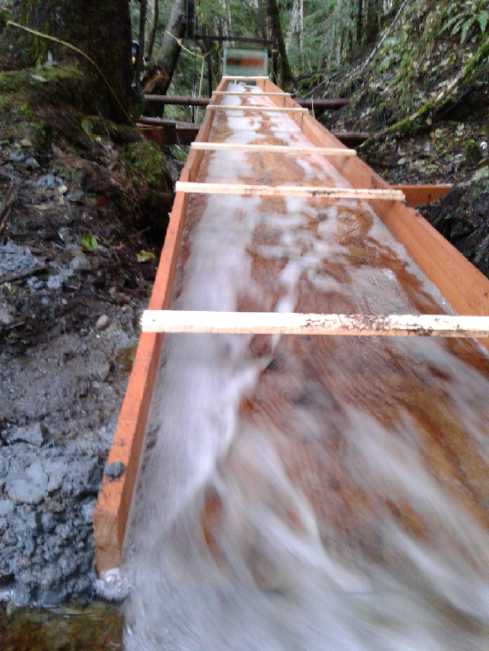
Assuming the outside was
intended to be stationary, it
looks a bit like it would be a set of (non-optimal) venturis that will
work regardless of wind direction.
I would remark here that I might get away with a fixed
venturi structure at my present location because the strong and
prevailing winds come from the east to southeast. Winds coming from
other directions aren't worth harvesting. Any winds from the westward
are damped through trees before they reach my house. South and north
winds are only occasional.
---
Later I looked at Analysis of Different Blade Architectures
on Small VAWT Performance (Journal of Physics - Conference series,
2016). This considered different fixed "Darius" blade "H" layout
architectures with 2 and 3 blades, straight vertical and helical (or
"tilted") blades. There
were lots of facts and figures, but it looked to me like the
performance of all of them wasn't too dissimilar - maybe within 15%.
Apparently 3 blades was better than 2, but they didn't try 4 or 5.
Helical gave more even torque with less vibration.
Tip speed ratios of 5 or more were graphed. When the
blades are moving so much faster than the wind, I'm sure there must be
an objectionable amount of noise for use as a home rooftop unit. Also
vibration except with the helical unit.
More difference in performance could be gained by means
discussed in a 2005 paper from Seoul Korea titled Efficiency
Improvement of a New Vertical Axis Wind Turbine by Individual Active
Control of blade Motion. By elaborate sensing and servo
control of a 4-blade "Darius" turbine they were able to get 60% more
power than from fixed blades. With more simple "cyclic" control of the
blades they got 30% improvement. It looked pretty elaborate and
probably expensive.
Something interesting they said (perhaps intuitive) was
that at the downwind half of the rotor the wind speed was half what it
was at the front. Since power depends on the cube of the speed, it may
perhaps be concluded that nearly all the power is developed in the wind
facing side. OTOH, surely that value depends on the number of blades
and how much of the wind they interrupt? Obviously a single blade will
have just as much wind wherever it is in the circuit.
Plywood Vanes?
On the 19th I made a "V" form from two bits of plywood,
put the PVC pieces in the oven at 235°F, and re-shaped them into
rough "V"s by pressing the floppy hot plastic against the form (with
oven mitts). (It reminded me of why I had made them 22" - it's about
the longest that would fit in a kitchen oven.) They seemed awfully
narrow. I had somehow expected them to be bigger.
By the next day I was wondering why one wouldn't just make
the vanes out of thin plywood. What could be an easier vane shape than
two flat sides? Plywood is cheap, so one could afford to mount quite
large vanes to get lots of torque from the wind. If it was also the
best simple shape one could make, so much the better! They could be
screwed and glued to some wedges of 3/4" plywood or short pieces of
board to close the ends, and easily mounted to more wood. (I still like
the 1.5" plywood with the metal "H" hub/bushing for the center of the
turbine.)
It would probably be the easiest way to do the folding
inside face, too. Of course it would all need some good paint and good
reinforcement if it was to be a permanent outdoor fixture.
Make & Test
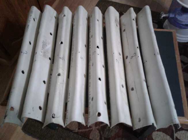 However...
there were the PVC vanes, and not wanting to
expend too much effort on this, I cut 8 wooden wedges to get roughly
the right angle, and screwed them onto the rotor. Next I had to wait
for a windy day. I didn't wait long. The 22nd was blowing a good gale
and I set it up about where I'd had it before in the "wind funnel"
driveway.
However...
there were the PVC vanes, and not wanting to
expend too much effort on this, I cut 8 wooden wedges to get roughly
the right angle, and screwed them onto the rotor. Next I had to wait
for a windy day. I didn't wait long. The 22nd was blowing a good gale
and I set it up about where I'd had it before in the "wind funnel"
driveway.
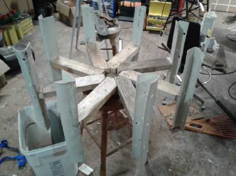 Put together
Performance
was different from the previous build only in
degree. Without a shield on the upwind side it still only got up to
around 30 RPM. With a shield it hit 70-80 RPM. That's apparently less
than 90-100 top with the last vanes, but first I have no way of
measuring the wind speed, and also the voltage readings with the same
meter were somewhat higher - closer to and occasionally hitting 2 volts
instead of 1.5, which should only happen if the speed is higher.
More significantly it seemed somewhat less affected by a
light load than with the other vane shape. With a 1 ohm resistor it
dropped to 50-60 RPM and still put out over a volt. (And the RPM meter
still worked)
With .45 ohms it dropped under a volt, meaning it was
putting out about 2 watts and the RPM dropped to about 40. Something
like twice the power of the other one, then?
(Again the appearance that the spinning blades are tilted is a "camera
trick".)
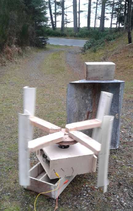 If
I
was to try anything more, it would be much wider
vanes to catch more air, but only 4 of them, or maybe 5 or 6... or even
3. 8 is surely superfluous (probably smoother, tho). And fewer
blades is surely less drag. And end caps on the "V"s at the top
and bottom - surely these are spilling air out the ends. Since it was
simple I tried removing half the vanes. RPM seemed to drop a bit to
50-70. It slowed down more with a load, to around 40 RPM with the
single .82 ohm resistor. But of course it wasn't wider vanes, just
fewer so less push.
If
I
was to try anything more, it would be much wider
vanes to catch more air, but only 4 of them, or maybe 5 or 6... or even
3. 8 is surely superfluous (probably smoother, tho). And fewer
blades is surely less drag. And end caps on the "V"s at the top
and bottom - surely these are spilling air out the ends. Since it was
simple I tried removing half the vanes. RPM seemed to drop a bit to
50-70. It slowed down more with a load, to around 40 RPM with the
single .82 ohm resistor. But of course it wasn't wider vanes, just
fewer so less push.
And I wouldn't bother expecting much without at least some
sort of folding vanes, or something like a wind shield. The upwind side
drag on fixed vanes really ruins
the performance. Or perhaps shaped airfoil blades would work much
better than vanes? If they are in-line as I saw in some units, they
shouldn't have much drag
going around. Since I didn't try those, the jury's still out.
Better would be some duct/venturi plan for directing air
onto the vanes and concentrating it. When the wind increased, one
definitely noted the improvement, and a venturi would greatly increase
the wind speed at the vanes.
I made the VAWT last month just to have something to spin
my new generator. Obviously the RPM (under 100) is too low for any
practical purposes with this generator unless I made a new stator with
far more windings of
finer wire, and unless I wanted to do that, I was wasting my time
making a VAWT. But somehow my consciousness gets sucked into thinking
about how to better do something, whatever it is.
OTOH, making some sort of venturi for a windplant might be
a good practice project before trying to make one for a tidal power
vessel. OTOOH (3 hands?) If a propeller is to be used in the tidal
power, why would I not try out a horizontal propeller with the
windplant venturi? And that might just spin fast enough to have the
generator put out useful voltage.
(OTOH again, if one is only going to get a few watts from
a windplant, perhaps one would be better off making the woodstove TEG
module generator as described in TE News #82 or #61. One would probably
get 10-50 watts, and that would be continuous as long as the fire was
on - ie, most of the winter. Perhaps one might simply put an
"overtemperature" alarm on it rather than any elaborate system for
dealing with overheat?)
Magnetic
Flipping HE Ray Energy?
A couple of things occurred to me after last month's try
at getting HE ray energy. First that the magnetic connection between
the inductor toroid and the steel on the "non-gap" side probably wasn't
as good as it might be. I decided to thread a bolt through it.
Second, it was said of some devices that they gradually
built up their
output and started working. I attributed this to them not having
properly powered control inputs,
but it was probably worth waiting 20 or 30
seconds to see if anything gradually started to happen.
A couple of other things I might try: more or fewer
permanent magnets, and perhaps (albeit dubiously), since I had moved
the gap to the other side, powering the "output" coil and seeing if
anything happened at the "input" toroid coil. Or, changing the gap to
the output side like Ivanov had it. But I don't see why the magnetism
shouldn't flip sides either way around.
HE Ray Converter Unit with plain steel parts.
3 blocks of mild steel form a "U" which is also the base - no gap.
A 3/4"x1/2" ferrite cylinder magnet and a solid 5/16"x3/4" bar make the
center leg - no gap.
Toroid (steel pipe) is bolted to left side. The flux gap is on its
right.
18 turns on each side (in opposite directions per Ivanov) wraps the
toroid.
Output coil is about 13 turns.
I decided just one magnet would probably be
about right,
and I cut
another bar to extend it across between the two sides, this time a
wider, thinner one, more in keeping with the rest of the plate metal
profile. I got it to where it was tightly wedged in and wouldn't move
with magnetic forces when the side bolts were tightened.
I tried to drill a hole in the ferrite(?) toroid, but it
seemed
harder than mild steel to drill and I wasn't getting far. Then I
thought that if I was using plain iron (well, mild steel) everywhere
else, that might as well be what the toroid was made of, too. I looked
all over, and finally found a small section of pipe just the right
size. I smoothed it off on the lathe and drilled and threaded a hole
for a 1/4" bolt.(22nd?) The gap at the other end was about .1". In
order that the wire insulation not chafe against the steel (smoothed
off or not!) I cut some tarpaper, wrapped it around the pipe, and taped
it on. (23rd)
Then I cut a 2.0 meter piece of AWG #15 magnet wire and
wrapped it,
half around each side of the pipe-segment toroid in opposite
directions. It made 17 turns with 6" of leed wire left over at each end.
One thing I'll say about this design if it works: there
are absolutely no unusual or hard to get parts in it.
A Water Wheel Hydro Power Project
I visited
the person doing the hydro power a couple of times. The first time, he
had made a plywood flume to direct the water into the wheel. That much
was working well; the wheel was spinning great.
But the voltage from the generator was only 2.5 volts. In
spite of the bicycle wheel rim to a small gear, driving a second gear
reduction, it wasn't turning fast enough. To charge 12 volt batteries
it needed another 6x speedup to get to around 15 volts. It pretty much
needs "bicycle rim to small gear, turning a second bicycle rim on the
second shaft, to another small gear on the generator".
I brought him a bolt down dual-bearing shaft with a large
and a small pulley that fit that diameter shaft (5/8"), in case it
would help. I found he had it hooked up again, but this time the water
wasn't running very strongly - it hadn't been raining enough. The wheel
was only turning about 30 RPM. There's a long way to gear up from that
to get say 1500 at the generator.
Rechargeable Battery Making
with oxalate electrolyte
Conductive Paint: Painted Copper MnO2 Pocket Electrode
Whether or not graphite
powder can be used with nickel electrodes, it certainly can be with
manganese dioxide ones. Epoxy paint having been suggested for making a
"waterproof conductive ink", it seemed worth a try. But already before
that, I had been planning to use pure copper for the next MnO2 pocket
electrode's pocket. In the last electrode the nickel-brass had turned
various colors as its surface oxidized and the nickel (apparently) had
become chloride. In earlier experiments copper was the metal that was
left in the oxalic acid when the nickel disappeared, and it was the one
that worked best in the first "from scratch" MnO2-Zn/KC2O4 cell.
(...notwithstanding the crappy connection to the terminal that has made
me want to do every electrode current collector/terminal since all in
one piece.) So copper seemed to be the most stable metal. It seemed
good now to try both of those at the same time. I had enough thin
copper sheet for 3 pockets in my chosen "standard size" - 2.5" x 5",
requiring (with the 1.5" terminal tab and for 6 mm (1/4") thick
electrodes), pieces 3" * 12" even. (The sheet was .012" thick. I also
have some .005" thick "copper foil" which I may try sometime if it
seems to work well. It would be easy to perforate and would weigh the
least.)
I cut a piece. This time I left 1/2" to fold over securely
at the top, so the cutout for the connection terminal was just an inch
by 1.5", with a 1/2" slit. (Okay, easier to see in the picture!) I
marked the folds in pencil on the outside face, then I went over the
inside face with scotchbrite/nylon scouring pad. Then I punched the
holes with a hammer and nail strip. It was substantially easier to
perforate than the nickel brass sheets. Nickel-brass is hard compared
to copper or brass. (Still a somewhat laborious job, but at least it
works! After milling lumber for weeks it didn't seem like a big deal -
at least to do a single electrode.) I "scotchbrited" the outside face,
then folded up the edges. I should have scoured that face too before
drawing the lines and punching the holes, so the edges of the holes
would have a clean surface too.
It weighed 51 grams - 10 g less than the nickel-brass, so
it must have been about 20% thinner. Copper isn't as strong as
nickel-brass. I hoped it was stiff enough. But
sometime I had found the plastic grille I had been looking for in the
summer, which I thought would make good separator pieces with lots of
support across the whole face, so if the cell was properly filled the
electrodes should press each other flat.
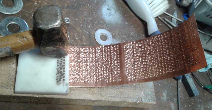 Perforating the copper electrode pocket. Finer
and more densly packed
Perforating the copper electrode pocket. Finer
and more densly packed
perforations would be much better. But this was what I found I could
do without special equipment that I haven't found to buy or figured out
how to make.
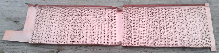
The next challenge was the paint. It had to be mixed with
graphite powder or conductive carbon black in good proportion to be a
water seal and yet with good electrical conductivity. It had to be
dilute enough so that it wouldn't clog all those holes I had just
punched, and at the same time, cover the copper well and not bead up.
Could all these conditions be met at all, and if so, how?
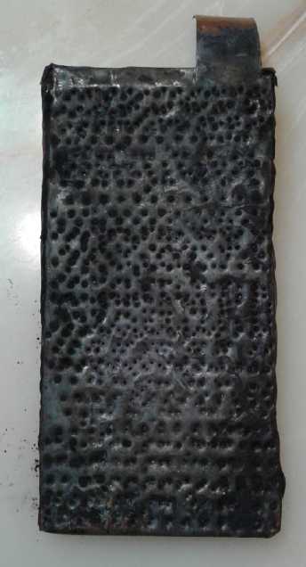 I didn't get
around to this until the 18th. I mixed 10
grams of yellow polyurethane paint with 2 grams of conductive carbon
black. (Naturally it became pure black.)
I didn't get
around to this until the 18th. I mixed 10
grams of yellow polyurethane paint with 2 grams of conductive carbon
black. (Naturally it became pure black.)
[
System Three
Marine Coatings (Well, it
was certainly going into a "marine" salt water environment!)
WR-LPU
Polyurethane Topcoat
BariteWorld.com
BW6304-Conductive Black
]
It was much too thick - almost dry. I added another 5 grams of paint,
and it was still a thick paste. I tried painting some on. Of course it
clogged up the perforations. Then I put just a bit of water in an
ointment jar [Pharmasave] and added a paintbrush full of the mix. It
was a lot thinner, but it still clogged the perforations. No doubt even
water would have beaded up and covered them.
I took a dry brush with somewhat stiff bristles and
started stabbing the outside with it as the paint dried. Eventually
light could again be seen through most of the holes. But it was a lot
of work, and the coating on the outside faces was definitely thinned by
the action of the brush. The insides wasn't because I didn't stab from
that side.
I left it overnight to be sure the paint was dry. In the
morning it looked like all of the holes were open again. Apparently all
I had needed to do was let it dry.
The
next
evening I filled the electrode with MnO2 salvaged
from regular "D" or "F" dry cells. With the paint it had been 51 grams.
With the MnO2 pasted in it was 144.7, so 93.7 grams of filler.
Generously assuming it was 25% carbon and Veegum, that's still 70.3 g
of MnO2.
My way of calculating amp-hours of a substance is simply
that I have zinc metal memorized: it's 820 amp-hours per kilogram. (820
was my address in Victoria) It moves two electrons per reaction to
become ZnO. Then one finds the molecular weight of the substance in
question: Zn = 65.4. MnO2 = 55 + (2*16) = 87. It only moves one
electron per manganese atom to become MnOOH or Mn2O3. So:
65.4 / 87 * 820 / 2 = 308.2 AH/Kg
308 amp-hours/Kg * .0703 Kg = 21.7 amp-hours theoretical
capacity (plus half as much again at a lower voltage if it gets too
discharged: Mn2O3 => Mn3O4). (The last electrode had 25 AH, so
apparently I didn't
stuff this one quite as full.) I pressed it to a couple of tons in the
hydraulic press and hit the sides with a hammer and screwdriver to sort
of crimp them shut.
Then I went in and started cleaning up the bench. I had mixed
two jars of MnO2 from dry cells. I noticed the label on one didn't say
"rinsed", and the material was pretty dry. It occurred to me that
perhaps I hadn't dissolved the ammonium chloride electrolyte out of the
stuff in that jar. A hazard of working on batteries so seldom; I
couldn't remember. If there was no omission on the label, I definitely
hadn't. I didn't want to contaminate my cell with chloride! The obvious
solution was to put the electrode in pure water so it would dissolve
out if there was any. Since it was now enclosed in the perforated
copper "pocket", I should leave it in quite a while and probably do 4
rinses instead of 3. Three or four days, then...
Once it had dried, the paint was so thin it was
translucent and it had coppery undertones from the metal beneath.
(Somehow more than the pictures seem to show) But
there were only a few points where it looked like actual copper poked
through. This is probably just about right. Hopefully the electrons
only have to go through a very thin layer of the paint before they hit
the highly conductive copper.
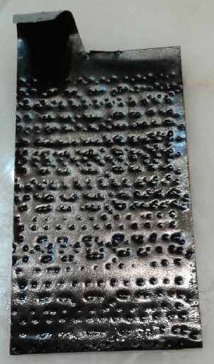
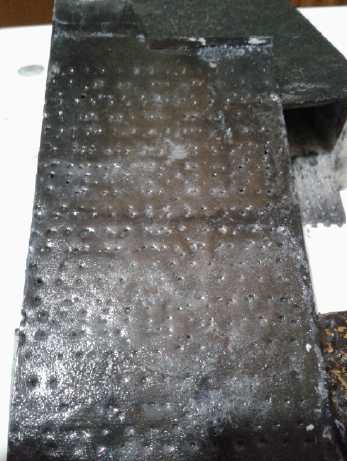 Zinc electrode etched, and then cleaned in
solvent
Zinc electrode etched, and then cleaned in
solvent
Assembly and Testing
During assembly I measured the "+"trode as averaging about
.26" (6.6 mm) thick and 130 grams.
The Layers of the
Cell:
plastic spacer,
MnO2 trode in conductive painted copper pocket,
plastic separator grid,
etched zinc electrode,
plastic spacers,
front of case.
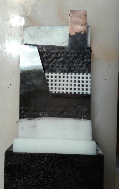 The
"-"
side was around .08" and 43 grams: 31 for the
sheet zinc and 12 grams of zinc powder sprinkled into it. It wasn't
very even (uneven "sprinkled by hand" powder distribution) so I
squeezed it in the press to about 3 tons to make sure there were no
places especially sticking up. This reduced it to around .06" - still
not very even.
The
"-"
side was around .08" and 43 grams: 31 for the
sheet zinc and 12 grams of zinc powder sprinkled into it. It wasn't
very even (uneven "sprinkled by hand" powder distribution) so I
squeezed it in the press to about 3 tons to make sure there were no
places especially sticking up. This reduced it to around .06" - still
not very even.
I cleaned out the cell case, and elected not to put the
other electrodes back in, to test just these new ones instead. When I
filled the cell and got a meter and test leeds (after a couple of
minutes) it measured 1.222 volts. Within another few minutes it rose to
1.242 volts all by itself. And then stayed there! I think that's a
definite improvement over perhaps all my previous cells, none of which
started voluntarily above a volt. That seemed like the right voltage
for the old dry cell MnO2 if it was discharged to Mn2O3 or MnOOH.
Within 1/2 an hour it was down to 1.238 volts, so (sigh!)
apparently my cells still had self-discharge. (Later I realized it just
about had to be from air getting into the cell. They have to be sealed!)
I tried an 11 ohm load and the voltage dropped to 1.04
volts. So much for better current capacity!
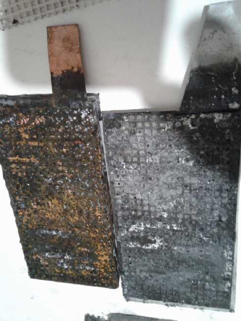 Then I put it
on charge at
1.7 volts. It didn't seem much different than the previous pair of
electrodes, drawing only 1/4 of an amp and dropping from there. But I
came back a couple of hours later and discovered that the cell was
shorted and the power supply was putting its full 5.5 amps into it. I
took it apart and discovered that all the squares in the separator
grille were filled with... something. Something solid but crusty and
brittle. I didn't think to take pictures until I had done some brushing
(toothbrush). I don't remember this happening with the previous pair of
electrodes.
Then I put it
on charge at
1.7 volts. It didn't seem much different than the previous pair of
electrodes, drawing only 1/4 of an amp and dropping from there. But I
came back a couple of hours later and discovered that the cell was
shorted and the power supply was putting its full 5.5 amps into it. I
took it apart and discovered that all the squares in the separator
grille were filled with... something. Something solid but crusty and
brittle. I didn't think to take pictures until I had done some brushing
(toothbrush). I don't remember this happening with the previous pair of
electrodes.
Could oxalate have some spontaneous reaction with zinc?
But the other side of the zinc electrode, facing away from the other
one, looked pretty much fine. With the MnO2 then? likewise, the far
side of that electrode looked pretty clear. And nothing bad had seemed
to happen until I started charging it, indicating the reaction was
electrochemical.
Could there be some substitution reaction occurring with
the calcium?
Ca(OH)2 => CaC2O4 ; K2C2O4 => 2 KOH ? Since CaC2O4 is
insoluble, it might build up between the electrodes? That seemed a
little unlikely. Perhaps some reaction between the MnO2 and the
oxalate, then?
A new thought occurred to me the next morning. Could the
zinc powder have somehow migrated through the perforations and ended up
between the electrodes? It was such fine powder it would no doubt fit
through the holes. And in charging up the MnO2 with the zinc side
already fully charged, hydrogen gas would bubble through it. Would that
really move it? Other than the conductive graphite PU pant (and
hopefully an absence of chloride), adding zinc powder was the
difference between these electrodes and the previous ones.
Where's that chemist who would know almost at once what's
really happening? I brushed off the positive side and
scraped off the zinc side and put it together again. If it did the same
thing, there was probably something wrong with the chemistry. If not I
guess it's okay. But without understanding the reason it happened. If
did it again but less I could try again even several times and see if
that would clear it up.
After I refilled it the voltage went by itself quickly at
first and then slowly from some low value to over .8 volts when I
hooked the meter up to 1.09 in an hour or so. With a few seconds of 11
ohm load it dropped to .8 volts, but rose quickly back to 1.08. Back on
charge it drew over .4 amps and dropped off more slowly than
usual.(11:15) This time it continued to charge without problems. I left
it on overnight and in the morning it was down to around 60 mA. Then
(26th) I put on an 11 ohm load. Instead of just running down to a volt,
I left it running for 10 hours, by which time it had put out around 660
mA-Hours, but mostly from voltages below .9 volts down to .6 volts. It
grew back to over a volt after an hour off load, then I put it back on
charge. Late the next morning it was down to "0.06" amps again.
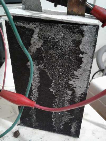 Solution coming out of the cell and drying on
the case.
Solution coming out of the cell and drying on
the case.
Should I have closed the top all the way?
Electrode Compaction & "Rivets"
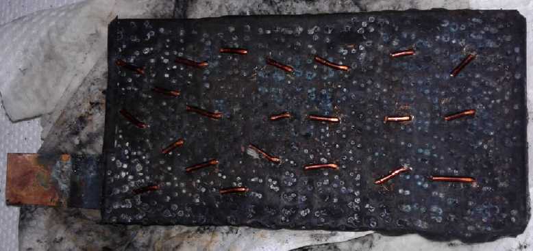 The maximum
short circuit current twice read 1.96 amps.
Yuk! Usually pocket electrode powders are much compacted, and the
pockets are very thin strips to keep the pressure on on the inside
"briquette". I decided to take it apart and crunch the electrodes
considerably harder in the press to see if that would compact the
powders better for - hopefully - substantially better current
capacities.
The maximum
short circuit current twice read 1.96 amps.
Yuk! Usually pocket electrode powders are much compacted, and the
pockets are very thin strips to keep the pressure on on the inside
"briquette". I decided to take it apart and crunch the electrodes
considerably harder in the press to see if that would compact the
powders better for - hopefully - substantially better current
capacities.
Next evening (28th) I drilled 5/64" holes through the MnO2
'trode. I put 3/4" lengths of AWG #14 wire through them and bent the
ends over "U" (should hold more solidly than "Z") to act as "rivets".
Then I pressed it to 10 tons, which pushed the wires in flush, denting
the copper sheet wherever they were. It had seemed dry, but the paper
towels got pretty wet with liquid that pressed out. So it must have
been better compacted. When it was finished it was about 5.5 to 6 mm
thick. (I weighed it, but by the time I went to write it down I had
forgotten the number and it was back in the cell. Probably it gained a
few grams with the bits of copper wire.)
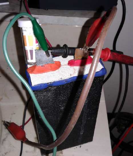 I cleaned
everything and put the cell back together. It
had been pretty much charged when I took it apart, but now it read only
.6 volts, gradually rising to .7 over a few minutes. If the zinc was
charged it should have read higer than that, probably around 1.2 volts,
so it must have been the zinc, sitting in air but fora while still wet
with electrolyte, that got discharged - turned to zinc oxide on the
surface. That seemed to be in keeping with what I knew about alkaline
cells, that the negative electrode will discharge on contact with
oxygen. Interestingly the rolls of zinc stay shiny. I guess if you
don't get them wet (especially with an electrolyte - hydroxide or some
salt), they stay fine in dry air. Or if they're soaked in electrolyte
in a battery, they also won't oxidize unless oxygen or OH- ions are
present. So the cells do need to be pretty much sealed. I think that
must be where most of the self discharge my cells usually have comes
from - air openings.
I cleaned
everything and put the cell back together. It
had been pretty much charged when I took it apart, but now it read only
.6 volts, gradually rising to .7 over a few minutes. If the zinc was
charged it should have read higer than that, probably around 1.2 volts,
so it must have been the zinc, sitting in air but fora while still wet
with electrolyte, that got discharged - turned to zinc oxide on the
surface. That seemed to be in keeping with what I knew about alkaline
cells, that the negative electrode will discharge on contact with
oxygen. Interestingly the rolls of zinc stay shiny. I guess if you
don't get them wet (especially with an electrolyte - hydroxide or some
salt), they stay fine in dry air. Or if they're soaked in electrolyte
in a battery, they also won't oxidize unless oxygen or OH- ions are
present. So the cells do need to be pretty much sealed. I think that
must be where most of the self discharge my cells usually have comes
from - air openings.
The cell charged overnight and was down to ".04" amps, the
lowest "idle" reading yet. I tried a short circuit. It put out over 4
amps for an instant but again dropped to ~.75 A in 10 seconds. Then I
tried a load test. It started from almost 1.6 volts, but it didn't hold
up anything like as well as the first test. All that effort seemed to
have made at best no difference. I didn't think much could go wrong
with a sheet of zinc, and it obviously works fine in commercial dry
cells, but now I became suspicious that that side was the problem, not
the MnO2 side at all. Perhaps, in spite of the pourbaix chart plus the
insolubility showing it as being ideal, it somehow didn't work right
with the oxalate electrolyte? Or was it something else that I had done?
As usual, the month ended with more questions than
answers. Why didn't things work as expected?
http://www.TurquoiseEnergy.com
Haida Gwaii, BC Canada