Turquoise Energy Ltd. News #127
covering
December
2018 (Posted January 7th 2019)
Lawnhill BC Canada
by Craig Carmichael
www.TurquoiseEnergy.com
= www.ElectricCaik.com
= www.ElectricHubcap.com
= www.ElectricWeel.com
Month
In Brief
(Project Summaries etc.)
-
In
Passing
(Miscellaneous topics, editorial comments & opinionated rants)
- No Clean Air Anywhere - Hybrid Potatoes? - Yikes! More California
Fire Stories? - Wonder Weather - BC
Referendum on Proportional Representation Results - ESD
- Project Reports
-
Electric
Transport - Electric Hubcap Motor Systems (no reports)
Other "Green"
Electric Equipment Projects
* Carmichael Mill Handheld Bandmill (more operating than building this
time) - Bonus Tip: stack excess firewood under a tree to dry
Electricity Generation
* Solar: Storage & Going Off-Grid, CAT & HAT plugs &
sockets - Real Life "Off-Grid" Tests during power failure
* Magnetic Flipping HE Ray Energy? - Dual Frequency Pulses - more tests
and trials
Electricity Storage -
Turquoise Battery
Project (Mn-Zn, Ni-Zn or Pb-Zn in Oxalate electrolyte)
* Ugh! Zinc hydride!
* Hydro - water storage
* Problems charging oxalate - JUST calcium hydroxide as electrolyte?
New Chemie Batteries
December's battery experiments disclosed several things I
hadn't understood or figured out before. First, it looked like the
whole oxalate idea just might have to be
thrown out the window. Whatever its other properties, oxalate seemed to
keep both nickel and manganese oxides from charging. (What did it do
with lead oxide? I can't remember and
can't be bothered to look back at that issue.)
What might I use for an electrolyte then? I was and am
very loathe to go to potassium hydroxide. After all its pH 14 solutions
are what causes zinc electrodes to degrade. The pH 12 where zinc
doesn't (according to the table) form a soluble ion had the promise for
long life, even everlasting, zinc electrodes. It finally, after all
these years, occurred to me to try just calcium hydroxide. That
had seemed like a silly idea because it's so little soluble. In fact,
that's why it's pH 12 instead of 14. But the result of very low
electrolyte concentration is just low current capacity per square
centimeter. Perhaps the best
answer to that is just to have more square centimeters. That's
certainly what's done with lithiums, which are made of very thin folded
up
sheets.
However, I'm going to try sodium oxalate before I give up
on the oxalate idea - either by itself or as an additive with the
potassium oxalate. Sodium-hydrogen sulfate seems to work wonders with
lead-acid batteries, so the sodium ion may act as a catalyst of sorts.
By itself it's not as soluble as one might hope, but 20 times more so
than calcium hydroxide.
Everything Else
Much of the month was pretty cold or windy and rainy,
which precluded working too long in the workshop or outside.
I wanted to continue (however slowly) with the reluctance
motor, but I only got as far as grinding off November's crooked weld-on
of one "salient pole" on the rotor.
 I set things
up better and did a couple more experiments
with the magnetic flip HE ray
converter, still without notable results, but I did learn a couple of
things. The oscilloscope showed I
had had some things wrong in my perceptions of what was happening with
the pulses. Now... perhaps an L-C tuned circuit can get some better
higher voltage switching happening?
I set things
up better and did a couple more experiments
with the magnetic flip HE ray
converter, still without notable results, but I did learn a couple of
things. The oscilloscope showed I
had had some things wrong in my perceptions of what was happening with
the pulses. Now... perhaps an L-C tuned circuit can get some better
higher voltage switching happening?
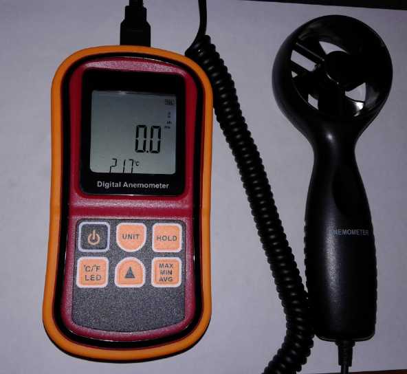 Being unable
to find either of my two anemometers for months, and even finally when
I
wanted to measure wind speed while I was trying out the VAWT, I ordered
another one. Quite a nice one this time, and I could take the
measurement part and tape it to a pole to check wind higher up while I
read
it from the ground. (The cable, whatever each wire actually did, had a
"USB" plug into the meter so I could add on a USB extension cord for
more length. I have trouble believing the reader unit actually sends
USB.)
Being unable
to find either of my two anemometers for months, and even finally when
I
wanted to measure wind speed while I was trying out the VAWT, I ordered
another one. Quite a nice one this time, and I could take the
measurement part and tape it to a pole to check wind higher up while I
read
it from the ground. (The cable, whatever each wire actually did, had a
"USB" plug into the meter so I could add on a USB extension cord for
more length. I have trouble believing the reader unit actually sends
USB.)
As I found, for wind power nothing is as important as
finding where the most wind is.
Where would I keep this one so I could find it when I
wanted it? I decided to put it on the shelf with my various voltmeters.
On the back of that shelf I found the better of the two missing ones.
The same
day the other one turned up in a messy drawer I had already looked in.
Sigh!
 And speaking of wind power
I found yet another VAWT video, by "New Forest R & D" that claimed
to be the world's best. It was a sort of a self-starting Darius rotor
that spun faster than the wind speed. It certainly seemed to spin well.
Unfortunately one couldn't make out the airfoil shape from the video.
(Someone commented on the silliness of making "tilted" blades, which
showed his own ignorance of how the unit is turning and has rotated
farther by the time the digital camera scans from the top to the
bottom. It would be easy to be fooled like that if I hadn't just seen
the effect in photographing my own rotor.)
And speaking of wind power
I found yet another VAWT video, by "New Forest R & D" that claimed
to be the world's best. It was a sort of a self-starting Darius rotor
that spun faster than the wind speed. It certainly seemed to spin well.
Unfortunately one couldn't make out the airfoil shape from the video.
(Someone commented on the silliness of making "tilted" blades, which
showed his own ignorance of how the unit is turning and has rotated
farther by the time the digital camera scans from the top to the
bottom. It would be easy to be fooled like that if I hadn't just seen
the effect in photographing my own rotor.)
If one could estimate the "wing" airfoils for optimum
lift/thrust, this one, perhaps a two-tier version, might be more worth
building than the simple "windjammer" Savonius types I've been trying
out.
 On the 15th
there was a big windstorm that blew down trees
across the highway and across the power lines in several places. On the
evening and next day while the power was out I finally installed some
of the solar power equipment that was sitting around and this is
written up as a project below. I was glad I had at least put the solar
panels on the roof last summer. Now necessity induced me to install the
charge controller and the 36 volt, 100 amp-hour NiMH batteries formerly
from the Mazda RX7-EV.
On the 15th
there was a big windstorm that blew down trees
across the highway and across the power lines in several places. On the
evening and next day while the power was out I finally installed some
of the solar power equipment that was sitting around and this is
written up as a project below. I was glad I had at least put the solar
panels on the roof last summer. Now necessity induced me to install the
charge controller and the 36 volt, 100 amp-hour NiMH batteries formerly
from the Mazda RX7-EV.
Using the 36 to 120 volt inverter wired to the Sprint EV
car, I ran the fridge and the freezer toward the end as the ice cream
had
started to get very soft if not to melt. I was especially concerned
that the well pump was 240 volts and I have no 240 volt inverter. I had
to forgo a shower even while the water in the tank would still have
been hot. But later in a store I found all the well pumps seemed to be
240 volts, so I guess I need to get an inverter for 240 volts. Keeping
the hot water hot in an extended outage is a problem for which I see no
simple solution. A water loop to the woodstove is a big plumbing job,
and the extra tank needs to be placed somewhere.
 I got a fair
bit of lumber milling done with my
handheld "Carmichael Mill" in spite of cold and rain, and I got the
automatic band sharpener working pretty well. Milling after the last
sharpening seemed as good as with a new blade.
I got a fair
bit of lumber milling done with my
handheld "Carmichael Mill" in spite of cold and rain, and I got the
automatic band sharpener working pretty well. Milling after the last
sharpening seemed as good as with a new blade.
After one more cant, I'll be able to clean up a part of my
driveway and drive around the circle, for the first time since I had
the trees cut down shortly after I bought the house. Wow!
The last 1/3 of the month
was a "write-off" - for energy
projects - as I went to my Mom's in Comox and then to Victoria for
Christmas visiting and some shopping. In that shopping I did get a 6
foot (x 1 foot) roll of .005" copper sheet/foil at Metal Supermarket
for making battery electrode pockets from in case I manage to make
working cells. (I hope that's not too thin. Their next choice copper
sheet was way thicker - .032" or something.)
I got back on January 2nd and didn't get going on
finishing up this newsletter until about the 4th, and even then not in
any hurry. (Do I have a deadline? well, I usually try!)
In Passing
(Miscellaneous topics, editorial comments & opinionated rants)
No Clean Air Anywhere
From what I've read
lately it appears there is now no clean air anywhere on the planet.
There is a considerable and increasing aggregate global level of
combined "EO-TOX" toxins we all breathe. At this point the Earth can't
clean its air of some of these without human intervention. That will be
a long,
slow process requiring new technologies to be developed. Even then for
that to work, first we have to stop polluting. Period!!!
The aerosol spraying program, now running evidently for
around 30 years, may not have made the world cooler, but it certainly
is helping to destroy it and poison the inhabitants. With the aluminum
and barium particles now in the air along with all the rest of the
eo-toxins being pumped into it from cars and trucks, factories, fossil
fueled power plants and heating systems, fertilizer and pesticide
spraying, nuclear
plant "exhaust" and other sources, apparently poor air quality has
become a recognized or
unrecognized contributing factor directly or indirectly in maybe 1/3 of
all deaths each year.
There are even still radioactive particles in the air from atmospheric
atomic bomb tests of the 1950s. (As a kid I remember we had to send off
our baby teeth for analysis when our adult teeth grew in because the
damage of these tests was being recognized. The Earth's Van Allen belts
grew stronger after each test, IIRC, and only very gradually subsided.)
Furthermore the ozone layer is evidently still getting
thinner. So
far it means increasing skin cancer levels, and is perhaps a factor in
some of the mass die-offs occurring around the globe. At some point
plants everywhere might start dying of short UV ray radiation and then
the deterioration of the atmosphere could become irreversible and
extinction of life would follow. I don't think we're there yet, and the
collapse is coming to help bring about an end to some of our
destructive ways, so, surely, it won't progress that far.
I myself had no idea things were this bad. Why did I
start reading along such subject lines? Maybe better not to know?...
but then again, maybe it helps explain my occasional coughing fits in
the last couple of years. After all I don't smoke... or do I? In this
and every remote corner of the world they chem-spray.
I bought an "air purifier" with a washable filter for the
house when I went south for Christmas. My present woodstove smokes
badly whenever the door is open - more pollution generated right in the
house. (I'll be replacing it next winter.) It said "whisper quiet" but
as I feared it turned out to be sort of an industrial sounding WHISPER! Noisy fans are everywhere!
So I run it at night on low at the opposite end of the
house from my bedroom. Hmm, I think it might be helping.
Hybrid
Potatoes?
 I left my potatoes from last
summer in the ground because they seem to keep better there. No doubt
if the ground froze very deep down, or perhaps if the soil had some
composition other than very sandy, that wouldn't work so well. I'm not
a big potato eater. I dug up a few on January 3rd after returning from
Christmas in Comox and Victoria.
I left my potatoes from last
summer in the ground because they seem to keep better there. No doubt
if the ground froze very deep down, or perhaps if the soil had some
composition other than very sandy, that wouldn't work so well. I'm not
a big potato eater. I dug up a few on January 3rd after returning from
Christmas in Comox and Victoria.
There's white and red skinned potatoes with white flesh,
yellow "yukon gold" potatoes with yellow flesh, and here we have purple
"haida" potatoes with purple flesh, light or very dark purple. The last
bunch I dug up were "haida". This time I just dug up 3 from a different
part of the garden for supper. Whatever are these? They have white
flesh.
I thought I had grown all my potatoes from the previous
year's potatoes, but with this skin they seem to be a hybrid or
something. Perhaps
some potatoes seeded themselves from the flowers and cross pollinated?
Anyway they're quite colorful potatoes! (Hmm... somebody might actually
pay extra for the colors!)
Yikes! More
California Fire Stories?
In a video (again by "aplanetruth") the author mentions
the population of Paradise, California as being well over 50000 people
going on more than one source. And the Weather Network said 18000
structures were destroyed. (Oops, was that in the Camp Creek
Road/Paradise fire, or overall for the state?) The media said the dead
were under 100,
and the "unaccounted for" peaked at 1200 but dropped to just 25 after a
couple of weeks. That sounds so good until it's turned around and the
people accounted for are counted instead, along with knowing
there were so many thousands of houses destroyed.
The author said he went around and found around 600 people
at the refugee camps. Doubtless some people would have driven off and
found other accommodation - friends, relatives, motels... That
might account for one or two or three thousand people. But say it was
5000... what happened to the other 45000
people? And in the surrounding area - more thousands?
The fire came on so fast and ignited so many places at
once that the main road in and out - with mountainous flames on both
sides and covered in dark smoke - was quickly jammed with vehicles.
There are a number of videos (dash cams?) from people who drove through
this inferno and made it out. Others abandoned their gridlocked,
burning cars and ran, but where could they go? The entire town was
obliterated. How could most of the population possibly have got out? A
tow truck driver said he counted over 200 bodies on a short trip in.
But many were burned until hardly charred bones or even just ash
remains.
The author said there are plenty of residents who aren't
posting to facebook and twitter any more, and he is starting a web site
hoping to find out what happened to them all. One starts to get the
impression of deaths on a similar scale to the nuclear bombing of
Hiroshima (50000).
In another video, a person recounted how he had been
through a big California fire before many years ago (he named the fire
and date)
in similar dry conditions, and how in spite of the wind it took hours
for it to spread from where he saw the first smoke to threaten the
town. This fire was completely different, he said. Even while the fire
seemed far away and there were no obvious flying embers reaching the
town,
pretty soon his house and the whole town was engulfed in flames. So he
ran to his car and left, within two minutes of first seeing fire. He
said he luckily had oxygen in the car, and that if he had taken two or
three more breaths he'd probably have died of smoke inhalation.
Apparently he got out before the gridlock hit, or missed it somehow. Do
we suppose his neighbors all got out okay?
There are some videos of the burned town, but evidently
the military has now taken over and no one is allowed in. Is there
something to hide? Where are the 50000 residents who want to see what's
left of their homes? Given the seemingly impossibly small 'casualty'
and
'missing' figures being spouted by the media, are they there to hide a
mass genocide? And "aplanetruth" is not the only one
calling it "mass murder". (The names, the names... Where would be a
copy of the Paradise phone book?)
I'm leaning toward to the conclusion that several
presenters are
right and that it's being done with "directed energy weapons" ("DEW"s)
- infra-red lasers or something similar - from aircraft. It would also
explain the "two sides of a rectangle" Fort McMurray fire perimeter
quite well.
Inventor Nicola Tesla offered the US military a "death
ray" of some sort during world war two, and his papers were seized by
the government when he died. And apparently they have been developing
"DEW"s since about 1998 with a budget of several billion dollars, so it
would be almost more surprising if they haven't come up with anything
than if they have. If this is really what is happening, perhaps we
should be grateful they're now using them on their own people instead
of on others, which could spark a world war.
But there are also some less bizarre aspects to these
fires; the ones that leave you saying "Well, that figures." With
housing so costly in and around the big cities, notoriously San
Fransisco, new
communities have been permitted to sprout up on "interface" border
lands between the urban and the seasonally very dry woods. They are
designed to lax standards with meager road access and laxly enforced
building codes and fire safety regulations. In short, they're thrown
out there into iffy zones previously thought to be unsuitable for
housing, because of population pressure, which makes them "accidents
waiting to happen." -- another result of the planet being
overpopulated. Then again, what about images like this? (here, in
Malibu):
 Forest fires burn down houses and leave
the trees?
Forest fires burn down houses and leave
the trees?
(...But how long after the fire was the picture taken?)
I'm definitely going to have to stop watching these
disturbing California fire videos! Just as with VAWT and many other
video topics, once you've watched a couple, Youtube keeps putting more
and
more of them in front of you as "suggestions".
Instead, maybe let's
follow the main
inhabited part of Alaska, where the ground has not stopped shaking
since the November 30th 7.0 quake? (but Alaska Earthquakes Center says
it isn't unusual - and okay, it finally looks a little more solid with
the
new year.) High waves and extensive coastal flooding are in store
for California this winter according to NOAA. If the worst predictions
for
much of the state sinking into the sea hold out, fires however started
may soon be the least of their problems.
From one video (by "Suspicious Observers", who
have a good record for earthquake prediction based on solar magnetism
patterns) I found out a theory for why there might be more flooding
than
just sea level rise would account for. It seems that (as I understand
it) as the ice sheets retreat
in Greenland and Alaska, the pressure on the mantle under those areas
is reduced, and the crust rises up. The mantle flows (seemingly from
especially the eastern and western seaboards farther south), causing
coastal California as well as South Carolina and most of Florida to
subside under the oceans. It is well known that Miami and New Orleans
will have to be abandoned just from sea level rise, but people there
are "in denial"; still
erecting new buildings in Miami and trying to improve protective
earthworks in New
Orleans.
Or how about the smoldering
Yellowstone supervolcano, its caldera 35 by 45 miles across, where new
geysers are chewing up the
walkways and roads and perhaps even the monitoring equipment? Is a big
eruption far
off as many insist, or it could blow very soon as some think. Mount
Saint Helens (its eruption in 1980 was heard from my house in Victoria
BC) was an anthill compared to Yellowstone.
Maybe some old British comedy shows would be a better
viewing choice?
Wonder Weather
But no, I had to check out
some more shows, on weather, and found the nastiest hail storms ever
recorded, from this last summer. In
South Africa (IIRC) one broke trees and killed cattle. One in Australia
only
killed
sheep (oops, and kangaroos). So in addition to the usual "once in 1000
years" droughts and floods, record high temperatures, record low
temperatures
and record breaking hurricanes, we now have nasty hail storms that
rain ice balls the size of golf balls and even base balls.
 Hail Storm in South Africa as seen from the
outside
Hail Storm in South Africa as seen from the
outside

It did this to this piece of forest (saplings?)

and it killed cattle
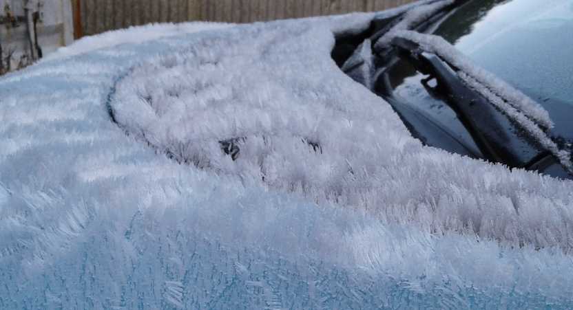
On Haida Gwaii we've had no snow (or hail), but one morning I
found a
strange "frost forest" covering the ground and on my car.
BC Referendum
on Proportional Representation: Results
Well, I guess there really are a lot of "sheeple" out
there.
Everybody complains about autocratic, dictatorial government decrees,
but the
proposal to reform our primitive, unfair and polarizing voting system
was rejected by 61% of BC voters (of the less than 50% who bothered to
mail in their post-paid ballot).
Reading some reader comments under the news story was
disheartening. I began to see the low levels of social awareness of the
general
population. To me, most of the "reasons" for voting against the
proposal seemed to be "cop-outs" - illogical rationalizations for
deciding not to take the trouble to give the matter any thought. Just
be negative
and nothing will change. That way it's impossible to make a worse
choice than the existing one. (It was impossible to make a worse choice
than that anyway.) Some thought it was just a waste of money. Some said
it was "too confusing", that "too many options" had been offered, so
(in spite of the option to simply vote "yes" and let others decide
which option to pick)
they just voted "no". Many voted against this measure to improve
election of governments just because they "don't trust the
government" - so "it must be some kind of trick" to get more money or
take more freedom from us! Premier Horgan and others in the new BC
government expressed disappointment with the result of what they had
championed as a means to change our polarized politics.
The one argument that seemed to me to have some merit was
that if a "majority government" isn't elected, it's hard to govern.
Decisions get bogged down in partisan bickering.
An unfair electoral system is the only way to get majority governments.
("Majority government" meaning over 50% of the entire legislature are
all from
just one political partisan sect ("party") - so much for the ideal of a
legislature being "a representative cross section of the society")
But that just highlights the need to separate the
executive branch from the legislative so that governing is separate
from legislating. Ideally both improvements - electing a 'governor'
separately from electing 'legislators', and picking a fairer electoral
system - would be adopted simultaneously.
We will not get another chance to make even this small
improvement to our governing systems before governments as a whole
start to lose cohesion and nation become largely ungovernable. And
obviously we'll need improvements to be offered
and promoted by local social sustainability design teams before the
general public will think proposals for improvements have credibility
and aren't something being foisted on them by corrupt leaders wanting
more control.
ESD
(Eccentric Silliness Department)
* Ducktors are just a bunch of quacks.
* Just when did "cocoa butter" become "white chocolate"? And when did
cadmium (as in screw and bolt plating) become "yellow zinc"?
* Russian anti USSA propaganda? "For 50 years, we wanted to live like
you. But no longer!" - Margarita Simonyan, head of RT.com . Maybe
it's because we don't have that life any more either. "The free world"
seems to have shifted markedly to the East.
* How many Microns in a Macron?
* The above mention of lax building standards in California raises
further questions...
- Can you relax without first having laxed?
- Can you relax when flying into LAX in a malfunctioning airplane?
- Are LAX (Laxton's Progress) peas better than Green Arrow peas?
- Do Green Arrow peas fly straighter than that airplane you're on?
"in depth reports" for
each project are below. I hope they may be useful to anyone who wants
to get into a similar project, to glean ideas for how something
might be done, as well as things that might have been tried or thought
of... and even of how not to do something - why it didn't
work or proved impractical. Sometimes they set out inventive thoughts
almost as they occur - and are the actual organization and elaboration
in writing of those thoughts. They are thus partly a diary and are not
extensively proof-read for literary perfection and consistency before
publication. I hope they add to the body of wisdom for other
researchers and developers to help them find more productive paths and
avoid potential pitfalls.
Other "Green"
Electric Equipment Projects
Carmichael
Mill ("Bandsaw Alaska Mill")
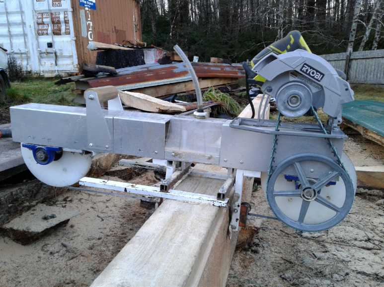
[ 20 minute Video: "Carmichael Mill Update" https://www.youtube.com/watch?v=P7r6hQF3yg8
]
 Other than
modifying the automatic band sharpener to get
it to work for my type of bands, which are lighter and have much finer
teeth than most bandsaw mill bands (3 per inch instead of about one),
there were no new developments in this project except the "Carmichael
Mill Update" video posted to youtube.
Basically it's a prototype that's working well and cuts
good, if often somewhat wavy, lumber. (More band tension and using
sharp bands minimizes waviness.)
Other than
modifying the automatic band sharpener to get
it to work for my type of bands, which are lighter and have much finer
teeth than most bandsaw mill bands (3 per inch instead of about one),
there were no new developments in this project except the "Carmichael
Mill Update" video posted to youtube.
Basically it's a prototype that's working well and cuts
good, if often somewhat wavy, lumber. (More band tension and using
sharp bands minimizes waviness.)
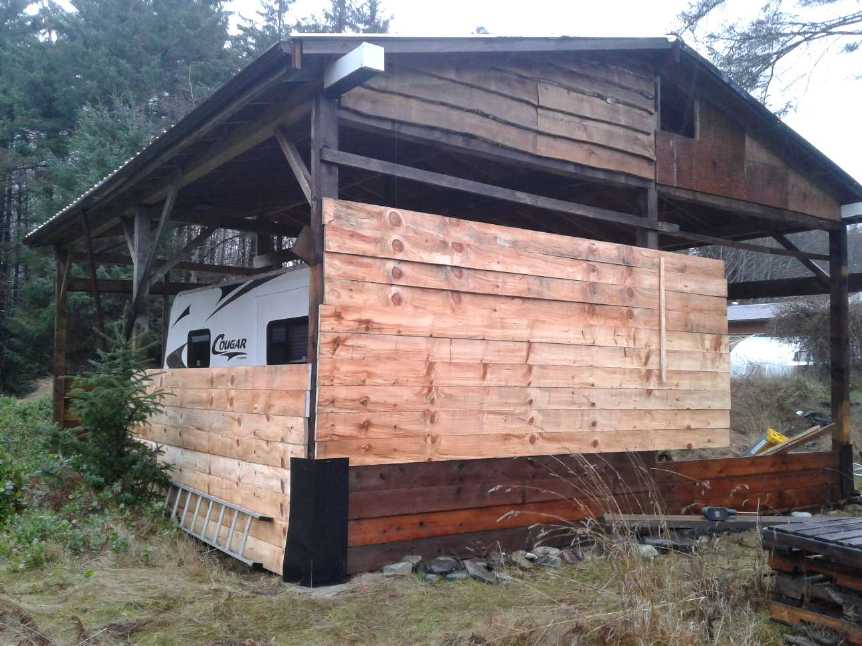
I cut the largest 16 foot long
spruce cant into eighteen 1"x8" x16' boards in the single digit days of
December. A chainsaw mill would have only made 12 or 13 boards and the
rest would have been sawdust. I put them up temporarily on the trailer
shelter walls with
deck screws, to block the wind and rain. (I screwed on the vertical
stick
seen in front and slipped the right end of the top two boards in behind
it
as they were too heavy for one person to lift and hold in place from
one end while screwing them on from on a
ladder. ...Left side: wall studs on 16 foot centers?) Everything held
in the big wind storms. It would be drier underneath if they covered
all 24 feet of the windward end, and from bottom to top.
 I started on the cant that was
underneath that one on the 12th.
While the sharpener took the better part of an hour sharpening each
band, and each one cut only 3 to 5 of the wide boards in the
tough-milling spruce, at least I didn't have to do the tedious
sharpening by
hand. It
allowed me to keep cutting instead of running out of sharp bands. One
band, sharpened 3 times, didn't seem to stay sharp long after the third
go. I switched to another one and once into the narrower cant, I got
quite a few good boards with it.
I started on the cant that was
underneath that one on the 12th.
While the sharpener took the better part of an hour sharpening each
band, and each one cut only 3 to 5 of the wide boards in the
tough-milling spruce, at least I didn't have to do the tedious
sharpening by
hand. It
allowed me to keep cutting instead of running out of sharp bands. One
band, sharpened 3 times, didn't seem to stay sharp long after the third
go. I switched to another one and once into the narrower cant, I got
quite a few good boards with it.
A guest watched my video and thought the mill could be
mass-produced to sell for 400$. He's probably right. I've thought about
making them, but I seem to be on to other things - except for cutting
up my own spruce. I'm thinking I may, after all, someday get through to
the
end of the ones blocking the driveway and be able to drive around the
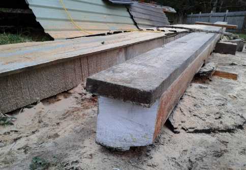
circle again. 2-1/2 big cants to go (and one to sell as-is for a big
beam) as of the 13th.
 One
development perhaps of note: I finally got the automatic band
sharpener working well.
One
development perhaps of note: I finally got the automatic band
sharpener working well.
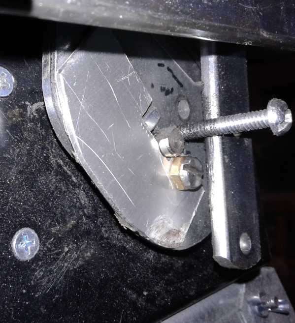
Earlier I put a bolt in closer to the center so the pusher
would
only push one tooth through at a time instead of two or three, and I
moved the rod from the
grinding wheel closer to the hinge so it went up and down less. Even
so, this month there was another thing: I put in a piece of sheet
aluminum on the turning cam so the grinding wheel travelled up and down
still less for each tooth. Then it didn't dig crazily far down in the
gullies between the teeth.
The next band cut like new again! The bottom of the cant
took about 4 minutes per cut for all three cuts, instead of 8 minutes,
10 minutes and 12 minutes with each cut being slower than the previous
one.
I may not report on the mill again unless there's some
interesting development, or if I'm especially proud of something I've
done using it. It's sure nice, with so many puzzling failures and
setbacks in other projects of potentially priceless value that I just
never seem able to finish, to have one nice one that I can say is done
(in
just one year!),
works great and I'm using it heavily, and which has advanced the state
of the art in
something. (Self-adjusting band guides seem to have never been thought
of before.) It cuts using less power and turning a thinner kerf into
sawdust than any other mill anywhere.
The mill (from the front) near the start of
January.
The original skillsaw's gears wore out - their
grease was gone - and it had to be replaced.
(Must open this one up and check the grease occasionally!)
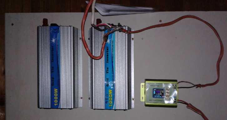
Solar: Storage
& Going Off-Grid,
12 & 36 VDC, CAT & HAT Plugs & Sockets
I still had the Honda
Insight batteries, a total of 32 sets of 6 NiMH super-high-current
cells welded together.
They had proved to be a frustrating setup, yielding as I saw it a
nominal 7.2, 14.4, 21.6 or 28.8 volts, which were all too far off to
use for 6, 12 or 24 volts. But I should have gone one further: 5 sets
in series makes 30 cells for 36 volts nominal, which is the voltage I
was saying
earlier is an optimum DC power voltage: 1/3 the current and wire size
of
12 volts, yet low enough voltage that no one will be electrocuted from
touching it. And it fills the gap right in between: at three times 12
volts it's also 1/3 of 120 volts common AC grid line voltage. (I
"officially" defined it as
38 volts with +/- 15% tolerance: 33-43.7 volts, which allows for all
the common "12 volt" battery types in all states of charge including
being under
charge. [Except high voltage pulse charging. If that is in use, the
power may need to be filtered to protect appliances/equipment.])
6 sets of 5 cell stacks, which are either 6.5 AH or 8 AH,
would give 39 or 48 AH of very high current capacity storage. They
would have no trouble running high load appliances, like perhaps the 36
volt to 120 volt inverter as it turns on the fridge or freezer. To that
could easily be added 100 AH in the form of my three 100 AH regular
NiMH D cell batteries for more storage capacity. And about another 100
AH of miscellaneous NiMH D cells if I wanted to add them in. These are
all surplus since I took them out of the Mazda RX7 EV some time ago and
with sufficient solar panels could tide one through a very long power
outage - at least in the summer.
Real Life Off-Grid Tests
Well, on the 15th came the opportunity - in fact the need
- to test things out. There was a strong wind storm up to 120 Km/Hr or
higher. I
went to a cafe for lunch. The road was cluttered with small branches.
The whole building shook. It was predictable: At about 4 PM the power
went
off. At 8 PM it came back on for a short time (10 or 15 minutes?) and
then went off again. At about 4:30 PM the next day, 24-1/2 hours later,
it came on and stayed on. I wondered how many
trees fell across the power lines in the tempest? A couple of days
later I saw a couple of pairs of them on a trip into town:
 Looking south; Hecate Strait [ocean] to left
 Another spot, Looking north
The outage demonstrated
that I was less prepared than I
thought. One thing I did have was of course the woodstove and
firewood, so there was no interruption to the heat. (And I had just
noticed a video suggested by youtube from Canadian Prepper: "You won't
last one off-grid winter without one of these.", with a picture of a
wood stove. Those living in regions with cold winters should take note
as people here and there have been without power for extended periods
recently.)
People talk of cooking on a woodstove, but my experience
is that the top of any newer "high efficiency" model is never really
hot enough to boil water. For coffee I put water on the stove for
hours, then I brought in my propane camp stove to get it boiling. It
didn't take much propane that way. In the morning I very, very
gradually cooked a pancake directly on the wood stove.
Electrically was where I wasn't so prepared. I had all the
pieces, and 1000 watts of solar panels sitting on the roof, so I was
surely far more prepared than most - but nothing was hooked up. It all
had to be installed and wired. In the gathering gloom I couldn't find
the 3 KW, 36
volt DC to 120 volt pure sine wave inverter. The just charged Honda
batteries
weren't all wired together for 36 volts yet. All my other big 12 volt
NiMHs proved to be pretty discharged, and they were the ones with 12
volt CAT sockets wired on so you readily could plug 12 V lights in. I
was hard pressed to put on a couple of low power lights for a few hours.
I thought I'd like to try two 12 volt LED globe lights
with round "power adapter" sockets on them. I found a wire with a
"power adapter" plug on one end, but I had to put together a CAT plug
for the other end. For that I had to find another battery that would
power an inverter so I could run the soldering iron. I also had to
grind the
few roasted coffee beans that I had to brew a small pot. (I keep
telling myself to keep some ahead in case of a power failure, but they
always seem to be all gone before I roast more.) I left the inverter
turned on but running nothing and within 1/2 hour its low voltage alarm
started going off - it had sucked what little charge that battery had
out
all by itself powering nothing. Making the cord paid off because one of
the globe
lights in low power mode drew only 90 mA - barely over a watt, yet it
was enough to see by. Surprisingly bright. I could leave that on all
evening even with the low batteries. (The 15 watt 12"x12" square flat
panel light was way more light, eg for reading, but drawing 1.25 amps,
the batteries wouldn't have been up to it for very long.) As always I
had my 6 volt bedside light with 5 D cells, which I do use and usually
keep well charged. Another 12 volt light sufficed for the kitchen to
make coffee and food.
The most problematical thing of all, which had been
preying on my mind ever since moving here, was that the well water pump
is 240 volts. I couldn't run it without grid power, period. If I ran
much water, the pressure would be gone and there would be none. I saved
it for toilet flushing and short bursts of running sink faucets. The
shower I'd meant to have had to be put off even though there was plenty
of hot water in the tank.
If I bought a 240 volt inverter, it would be just for the
pump. And if it failed, I wouldn't have any other to use. I have
several inverters for 120 volt appliances. Plus the pump was wired
straight into the sub panel in the shop: even if I had the inverter,
I'd have to un-wire the pump and reconnect it, with the cover off the
panel. I added "120 well pump" to my shopping list. I'd wire it
plug-in so it can be plugged into an inverter if the wall is dead. But
in Canadian Tire on my Victoria shopping trip, I only found 240 volt
well pumps, and they were 300$ and up. Perhaps a 240 volt inverter is
the thing to get after all.
The next morning I disconnected the grid tie inverters
from the solar panels and put on the programmable DC to DC charge
controller. I set it to 42 volts and dragged in the 'pretty discharged'
100 AH - 12 V NiMH batteries, and set them in series. Over the course
of the cloudy, rainy day, the power from the 1000 watts of solar panels
went from 10 watts around 11 AM (or whenever it was I'd got it all done
by) up to almost 80 for a couple of hours and back to 10 by 3 PM. Short
cloudy northern days with the sun at a low angle aren't optimum for
solar. The controller said it had put a whopping 2.1 amp-hours into the
batteries, which just hit 39 volts.
 I took the two pairs of wires, each coming from
two
solar panels, and tied them together.
I took the two pairs of wires, each coming from
two
solar panels, and tied them together.
(The screw terminals on the grid tie inverters are too short to put in
more than one wire,
the MPT7210A only takes one skinny wire per connection, and I didn't
have a heavy
terminal strip, so the connections are hanging in the air tied together
on two bolts - Ugh!)
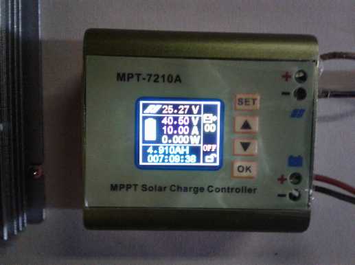
The charge controller, set to charge to 40.5 DC
volts at up to 10 amps.
I could float charge them up to 1.40 x 30 cells = 42.0 volts, but there
seems
no
reason to push them to the max if they'll be charged every day and not
much used.
(Solar panel input is usually 32 volts open, 29 volts charging, but it
was just getting dark outside.)
This unit works well, but the instructions are so inadequate for
setting up its many programmable
features that people have put up youtube videos that explain how to get
it to do what you want.
The solar panels are 1000 watts, but in the cloudy winter weather
with the low sun angle I
don't think it's hit 100 watts charging yet.
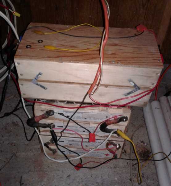 Three 100 amp-hour, 12 volt NiMH batteries to
make 36 volts.
Three 100 amp-hour, 12 volt NiMH batteries to
make 36 volts.
(Beside them are some 12 V, 10 amp-hour tubes. I'm connecting and
charging one each day
since I haven't got enough wires made up to connect them all together.)
Breaking the narrative here, Jim Harrington of AGO gave me
a link to the MPT7210A programmable charge controller and I got
two because they sounded like they would do just what I wanted. Now
from the many youtube videos about it, it sounds like this is in fact the
one to get for many purposes. It has a zillion ways it can be set up,
and even multiple setups can be programmed in. The biggest complaint is
the fan noise, which is terrible, and it blasts away regardless of
temperature. The speed is supposed to be programmable, but doing the
same thing that seems to work in a video does nothing on mine.
The other complaint is the complexity of operation. How to
use it goes from poorly explained to just not explained in the brief
manual. And there's nothing intuitive or simple to setting it up.
That's the main reason there are so many videos about it. There are
just four buttons, but they do many different things depending whether
the unit is charging or not, which one is pressed first, whether it's
held down or pressed quickly, and the entire sequence.
For example, to set it to auto-on when the sun comes up
and it powers up: 1. Hit "OK" to turn off charging. 2. Hit set about 4
times until "Amps" is highlighted. 3. Press and hold "Set" again a few
seconds. 4. Hit "Set" again 3 or 4 times until "OFF" is highlighted. 5.
Hit "up arrow" so it says "ON". 6. Hit "Set" again. 7. Hit "OK". Then
you can turn it on again by hitting "OK". The manual doesn't explain
this. I had to watch part of the video, go out and do the first steps,
then watch the rest of it and go out and finish it. I can't help but
think it could all be made a lot more intuitive even with just the same
four buttons and the same display. Meanwhile, back at the ranch...
By early afternoon the ice cream in the fridge's freezer
was melting or at least very soft, and the small chest freezer was up
from its usual -22°C to -10 under the lid, notwithstanding that the
room/garage it was in was probably only 7 or 8 degrees. (It was
probably colder down lower in the mass of frozen food.)
I got out the 36 VDC to 120 VAC inverter (I did eventually
find it) and connected it to the 36 volt, 300 amp-hour Sprint car -
half the storage of the Nissan Leaf, but accessible. I had been
keeping its batteries pretty well charged, and of course lithiums don't
self-discharge as fast as NiMHes. (How was it that I had to attach
wires
by removing nuts and hard-wiring up the inverter to the car instead of
just plugging it in somewhere?) I ran a 100 foot extension cord to the
house. I put in the Canadian Tire appliance power meter and plugged in
the fridge. It was using about 170 watts, which gradually dropped to
under 140, drawing around 5 amps DC from the batteries according to the
clamp-on ampmeter. I ran it an hour or more until it stopped. It soon
started again, but I unplugged it and plugged in the coffee roaster
(popcorn popper) and roasted one batch, taking about 3 minutes. The
1500 watt roaster would have used in 3 minutes what the 150 watt fridge
does in half an hour. After that I plugged in the chest freezer, which
drew just under 100 watts. By this time it was mid to late afternoon.
After an hour of that the power thankfully came back on. The car's
batteries had started at 39.6 volts. They soon dropped to 39.0, but
stayed there for the rest of the event. (Except when roasting coffee
they dropped a little farther, but came back up to 39.)
My conclusion is that while not much happened during a one
day off-grid event (other than frantically setting everything up and
wiring it, and missing a shower), a longer period would bring serious
hardships as things are
set up now. OTOH it was a good day to run around setting things up...
there's a whole bunch of other things one can't do anyway if there's no
power!
First and foremost, I definitely need a well water pump
that I can plug into a 120 VAC inverter (or else a 240 volt inverter).
Then,
for a period more than
two or three days, I need more power generation for lights, fridge and
freezer. The Sprint car, if kept charged, can run them for a while, but
not
more than a week or so. After that it would depend on the sun coming
out to recharge the batteries. And it would take still more available
power to
keep a computer or two running. Milling with the electric band mill is
out. Firing up the gasoline generator for fridge and freezer is a
stop-gap
solution for a few days. Combining the wood stove and the propane
camp stove for heat should suffice for meals and coffee for a very long
time. The woodstove would have to do for hot shower water, too. Ugh!
A 20 to 50 watt thermocouple generator to put on the wood
stove, that would run 24 hours a day, starts to sound like a good idea
again, if that's all that can be had out of solar panels in the winter
anyway. If the modern woodstoves don't get so hot on top as the old
ones, perhaps it could be done with TEGs ("Thermo Electric Generators"
- higher temperature Peltier
modules) without any special overheat protection needed. The number of
modules could perhaps be selected to send a voltage to the solar
controller similar to that of the solar panels - but it would work all
day and night.
And if I'm going to have my "optimum line voltage" 36-40
VDC system, I need to start looking for some appliances that use that
voltage. All I have presently for that voltage is the Sprint car and
the inverter. Maybe I can put three 12 identical volt LED lights in
series? It'll probably work, but it's a makeshift solution.
And I need to finalize the design and start producing the
"HAT standard" 38 volt
wiring products: Plugs, Sockets, electrical box Wall Plates, and so on.
In the meantime, I had the CAT plugs and sockets. After
doing some 12 V wiring I decided after all, there was little point in
changing the standard. CAT is quite good, fine as it is. There would be
no RAT (Revised CAT) standard. Changing it poses two problems. One is
that any little bit of traction it might have gained as an adopted
standard so far will be broken. It was probably even a mistake to say I
would change it some issues back. The other is that I haven't had time
even to set up the 3D printer. How much time do I have to redo what's
already done?
I had planned to make the 36-40 volt HAT standard plugs
and sockets about the size and shape CAT is now. What I do need to do
instead is make it different enough so that you can't accidentally plug
the one into the other and underpower 36 volt equipment on 12 volts or
blow up 12 volt equipment on 36 volts. Perhaps the thing to do would be
to make the proposed "RAT" standard, or something close to it, into the
"HAT"
standard. I guess nothing will be settled on HAT until I get on the 3D
printer and start making something.
I managed to cross voltages without HAT plugs. I had the
36
volt battery system on the solar panels, and during the power failure I
had connected one 12 volt battery of it to the wire running across the
house to the closet by the living room. I wired in a CAT duplex
receptacle there and ran 12 volt lights off it in the living room.
Later I had been charging some other batteries and used the alligator
clip jumper leads. When I reconnected to the wire, I absent-mindedly
connected it across all 36 volts instead of just 12.
When I turned on one of my 12 volt homemade LED lights, on
"low", it was amazingly brilliant for about one second, then it went
out. Oops, the "12" volts was 39! I moved the alligator clip wire.
Later I started taking the lamp apart hoping I could repair it. Wait!
There was a fuse! What a clever idea! Amazingly the 2 amp AT fuse had
blown and protected the lamp. I put in a new one and
it worked again.
But if I had connected the wire with a CAT plug to a CAT
socket - already present on each of the three batteries - instead of
with jumpers, the incident could never have happened. This just
underlines the need for proper and unique plugs and sockets for each
voltage: IMHO: 12 VDC, 36 VDC, and the existing ones for 120 VAC and up.
On the 19th I wired up my indoor garden fan, a battery,
and a 10 W solar panel with CAT plugs and socket. (Since the panel is
just 10 watts, I don't bother with a charge controller. I put a diode
in series next to the plug so it can't draw charge back when it's
dark.) Why had I been using aligator clip leads that keep breaking and
falling off for this little system all this time?
And I found the need for a couple more CAT type products.
First, If the solar panel is a power source rather than an appliance,
it should have a socket rather than a plug. But if it does, how do you
plug it into a battery that also has a socket? Apparently a plug-plug
"cheater" adapter is required. Second, I wanted to plug both the fan
and the panel into the battery at the same time. I have before put two
CAT sockets onto
a battery, but this time I thought it would be nicer to have a splitter
with a plug and two or more sockets on it, similar to those that grace
so many
120 volt wall receptacles because there are never enough of them.
Then, not to get too carried away, a very useful device
for off-grid power would be an in-line power meter with a plug and a
socket, to show the voltage and current. ...a low power one with an LCD
display that wouldn't itself drain the battery.
Finally after having them in use for a couple of weeks, I
am reluctantly forced to conclude that the 100 AH NiMH batteries are
rather worn out. One of them discharged itself from 13.5 volts to 12.7
overnight (about 17 hours) without a load. I think it was the continual
float charging in the RX7-EV that gradually wore them out. Better to
just charge them at a good speed and then turn it off and let them
rest. And they are several years old now. Of course they're also being
float charged all day on solar. For now in the dead of winter that's
only about 6 hours, and I turned that float down from 1.40 volts per
cell to 1.35 - total 40.5 instead of 42.0 volts. I expect the lithiums
take a float charge better because they stop drawing current once
they're charged.
But it all makes me the more determined to come up with
better, cheaper batteries. There's no way batteries should cost the
sort
of money they do. I keep thinking there can't be much more in the way
of getting a better, cheap chemistry to work as expected, after all the
progress I've made and all I've learned.
Magnetic
Flipping HE Ray Energy?
Okay, nothing
happened in my one try at powering the device up in November.
What else could I try?
* Dragging out the oscilloscope so I could see what's going on - actual
waveforms and voltages at various points.
* an antenna (Moray's earlier devices had one)
* a ground connection (Moray's devices all needed one, as I recall)
* Putting Diodes in series with the pulse source. 36 volt pulses are
nice, but since the motor controller doubtless
has rectification to capture the return energy, the big
spikes across the coil will be damped out. The big spikes
at turn-off of the pulse were a requirement. (How could I
have put that out of my mind?) If I put diodes in,
they can isolate the coil and let it fly. (When one works
it out, this was a mistaken assumption. The spike's reverse voltage
makes the diode forward biased anyway.)
On the 12th I thought, what was the real problem with
working on it and running tests? I started out in the summer with the
car out on the lawn. Now as long as I was using the Sprint car's motor
controller as the 36 volt pulse source, I was working on the floor of
the garage. It's winter and it's cold out there. Plus it's cluttered.
In fact, it's cluttered almost everywhere I work. Perhaps these were
the things I should deal with first.
Two things I could remedy quickly I did on the 13th: I
cleaned up the corner where I had been working, and I cleaned up a bit
of wood clutter by making it into a work table (long planned - just
needed legs), which I then set in the corner and picked the experiment
pieces up off the floor.
Dual Frequency Pulses
Having a table to set it where it was high enough up to see the
screen and where I wouldn't step on it or kick it, I brought out the
oscilloscope and checked just what pulses were coming from the motor
controller. It was set to 1.6 amps, the minimum, and I found it had two
components: a
low frequency "square wave" with the "high" part being composed of high
frequency pulses. The low frequency was 8 mSec of the spikes then 8
mSec off: 16-17 mSec. (60 Hz). The narrow spikes were about 3 uSec. If
I turned it up to 2 amps, then 2.6 amps, the pulse width increased to
about 4 and 5.5 uSec, but the overall pulse rate remained the same -
straight PWM at 16000 Hz.
I had connected a wire to one side of the input as an
"antenna". The unconnected scope probe picked up the pulses from being
near it, but nothing was obtained at the DC output (which I only
metered with a voltmeter) except a voltage that gradually rose from 0
to .15 volts over
a couple of minutes. I also tried reversing the pulse leeds in case the
pulses were the wrong polarity compared to the magnet.
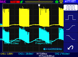
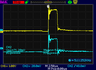 Zoomed out, a bunch of high frequency pulses is
followed by
quiet, each 8 mSec for 16+ mSec periods (about 60 Hz)
Zoomed out, a bunch of high frequency pulses is
followed by
quiet, each 8 mSec for 16+ mSec periods (about 60 Hz)
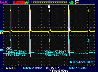
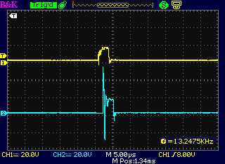
Zooming in on the pulse areas, each one is composed of short pulses
with about 62.5 uSec period (16000 Hz)
Zooming in still further, each short pulse is about 2.5 uSec.
As to amplitude, the scope probe on Channel 1 is x10, and it's driven
from ~40 V lithiums.
But it's a heavy load and a long, thin wire, so we see around 30 volts
(says ~3 V @ 10x scope probe).
(Channel 2 is only picking up noise from the "antenna", so the
amplitude
depends only on the pick-up. I should have turned it off.)
Perhaps interesting: the ground clips of both probes were unconnected -
I wasn't sure where there was a ground -
and the car should have been floating, yet solid readings were attained
on Channel 1.
 Increasing the current setting increased the
width of the pulses.
Increasing the current setting increased the
width of the pulses.
But the 16 KHz and 60 Hz overall frequencies didn't change.
I don't know what led me to want to try the car's motor
controller as a 36 volt pulse source. Somehow it just seemed like the
thing to do. Now I see a potential advantage to it over any pulse
generator I would have made for myself: I don't think a steel/iron
"core" material will respond well to a higher frequency like 16 KHz.
But it should turn on and off at 60 Hz just fine. A single frequency
pulser would have to put out the same microseconds-short pulses at, eg,
60 (or perhaps 100 or 120) Hz, which wouldn't put much energy into the
field.
So this dual frequency of pulsation just might be a good
key to getting such a unit to work with an ordinary iron core instead
of some of the more exotic core materials others have used. (And such a
setup, providing an absolute maximum 50% duty cycle with 1/120th of a
second rest periods, probably would keep my motor controllers from
blowing up, too! That may be why Curtis adopted it. I'll try that on
the reluctance motor controller in future tests. Something else I've
been missing all this time! My first motor controller was very low
frequency, but I never got the idea for combining high and low
frequencies. Nothing in any of the motor controller chip data sheets
suggested such a thing, either.)
Now that I understand that the pulses are of this special
special nature I can make a driver to generate similar pulses and
variations on them. In fact, I can use the circuit I already designed
with the microcontroller - eliminate two of the three coil drivers and
change the MOSFET driver to one of the better ones I bought. Then the
whole thing can move indoors. I should have looked at the pulses last
summer! I suppose again working on the ground made me subconsciously
reluctant to bring the oscilloscope out.
[At some point here I noticed one could set the oscilloscope for "x10"
probes in a menu so the numbers shown on the screen would be correct.]
 Before doing
that, the next thing to try was to block the
suppression of the flyback at turn-off, by putting a high voltage,
fairly
high current diode in series with the pulse source (instead of across
the coil to damp it when it shut off). I tried on the 18th. I found I
only had lower voltage diodes, but I had an IRF840 Mosfet good for up
to
500 volts. Its body diode was good for a fair number of amps, so I
soldered
the gate to the source so it would never turn on, and soldered two
wires
to it.
Before doing
that, the next thing to try was to block the
suppression of the flyback at turn-off, by putting a high voltage,
fairly
high current diode in series with the pulse source (instead of across
the coil to damp it when it shut off). I tried on the 18th. I found I
only had lower voltage diodes, but I had an IRF840 Mosfet good for up
to
500 volts. Its body diode was good for a fair number of amps, so I
soldered
the gate to the source so it would never turn on, and soldered two
wires
to it.
I checked it out on the oscilloscope and found there
didn't seem to be a very notable spike. It seemed to me the coil should
have far more turns, of finer wire. (Channel B goes straight to the
motor controller. Channel A goes through the 'diode'. I thought it was
thus free
to spike as far negaitve as it wants, but it only did a few volts.) One
of the problems with energy device documentation is that it seldom
seems to give the size, characteristics and number of turns of the
coils.
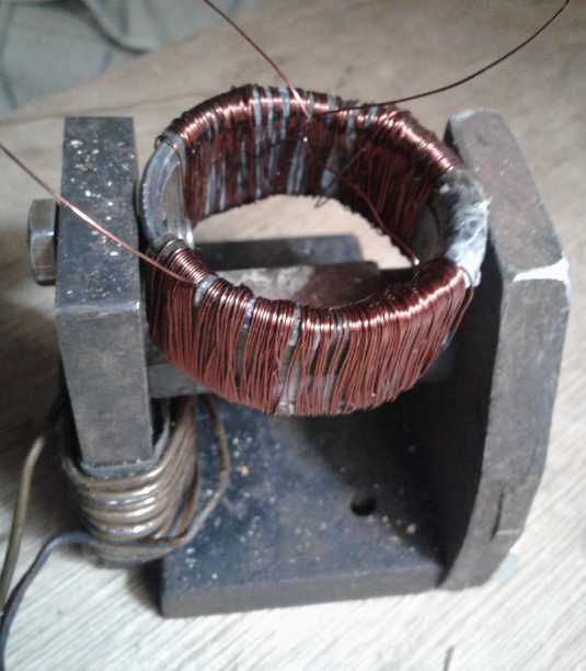
 Let's see... there are presently (were) 16.5 turns on each
half of the coil. If that little turn-off spike is maybe 9 volts, and
we want 100 volts, we need 11 times as many turns, or 183 turns (give
or take a couple of dozen). Let's see... unwinding one, it's less than
4 feet of wire. So make it 45 feet to be safe. That's probably more in
keeping with typical wiring for that sort of voltage... but much harder
to thread through a toroid, and to keep count while doing so! I found
some #19 AWG wire. That was about the thinnest I had much of without
going really fine. I wound it, but I'm not sure why I continued after a
certain point. It was obviously too bulky. Even #22 would have been a
dubious fit - 24 or 26 would have been better.
Let's see... there are presently (were) 16.5 turns on each
half of the coil. If that little turn-off spike is maybe 9 volts, and
we want 100 volts, we need 11 times as many turns, or 183 turns (give
or take a couple of dozen). Let's see... unwinding one, it's less than
4 feet of wire. So make it 45 feet to be safe. That's probably more in
keeping with typical wiring for that sort of voltage... but much harder
to thread through a toroid, and to keep count while doing so! I found
some #19 AWG wire. That was about the thinnest I had much of without
going really fine. I wound it, but I'm not sure why I continued after a
certain point. It was obviously too bulky. Even #22 would have been a
dubious fit - 24 or 26 would have been better.
So I went to
look for the fine magnet wire that Jim at
AGO, having had no use for it for quite some time, had virtually thrust
upon me. I didn't think I could possibly use it, winding lower voltage
motors as I was at the time, but this is the use! There was a spool of
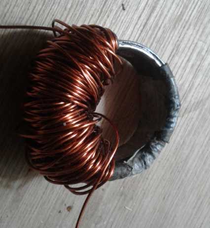
#28 AWG and
one of #30. I used the #28. Thanks Jim!
And I was thinking, that if the pulse widths were wider,
the spike voltage would be higher. So I decided to wind just 100 turns
on each side. If the voltage was too low I could widen the pulses to
put more energy into the coils. I don't know what a good voltage is
anyway, just that it's a lot higher than single digit volts.
The outer diameter of my pipe "toroid" was 45 mm, the wall
thickness was 3 mm, and the height (pipe length) was 19 mm. It took
over 14 feet of wire to do each side. (according to my calculator.)
On the 20th I wired it up,
took it out to the garage, and
connected the motor controller and the 40 watt lamp. This time, the
pulses looked nothing like the previous ones. There was no 60 Hz, just
continuous 16 KHz pulses, and instead of being a very low duty cycle,
they were around 90% ON. Apparently the controller was unable to put
the set 1.6 amps into the (effectively) 50 turn coil of #28 wire, so it
was putting out all the voltage it could, trying.
I tried taking out my two 22 ohm, 10 watt resistors, to
provide a load. In parallel, (11 ohms) the controller kept saying
"field coil output shorted". With 44 ohms it worked sometimes, but it
was still long pulses with no 60 Hz 'off' times. And the resistors got
very hot pretty fast. With 22 ohms, it mostly said "shorted" but worked
one time and still had full pulse width and no 60 Hz. Apparently the
car's pulse generator was expecting motor field coils for a load and it
wasn't going to give me what was wanted now that my coil was probably
close to what was needed. Unless I managed to load it down just about
the same way it was before, and connect the unit in parallel with that.
 Thinking of that, I got
out the original coil from last summer and did that. It worked - at
least, sometimes. (The other times, the motor controller says
"shorted", which has been happening all along.) When it did it gave the
desired pulse forms: short
pulses at 16 KHz going on and off at 60 Hz.
Thinking of that, I got
out the original coil from last summer and did that. It worked - at
least, sometimes. (The other times, the motor controller says
"shorted", which has been happening all along.) When it did it gave the
desired pulse forms: short
pulses at 16 KHz going on and off at 60 Hz.
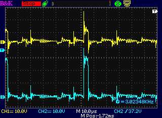
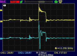
Probe "A" was mistakenly on the "+" side of the drive,
before the diode. "B" was after the diode, on the anode. Instead of a
spike at turn-off, the big spike was immediately at turn-on. Why? It
was around 95 to 125 volts from peak to peak as it went negative in
less than a microsecond.
This is probably about the right range. The only problem
was that there were still no results. No output.
As it got dark I went inside and drew it out on paper.
There were so many things that could be one way or another - so many
binary "1" and "0" choices... Diode polarity. Magnet polarity. Drive
polarity. And there was another one: polarity of the two coils, one on
each side of the 'toroid'. I had connected them opposite since they
were on opposite sides of the toroid. But that was wrong, wasn't it?
With the drawing there I realized that instead of both sides pushing
the magnetism from the magnetically connected end toward the gap end,
one was pushing one way and one the other, around in a circle. Net
result out into the iron horseshoe: zero. I swapped the two ends of one
of the coils.
The next day I went out again and figured out some more.
The spike at turn-on instead of turn-off was because the diode was the
wrong way around.
The rise was simply the turn-off time of the diode, and the fall was
because the diode stopped conducting, so it was like "turn-off". But it
was just stray transients. There hadn't been much time for energy to
accumulate in the coil, so there would be no notable magnetic output.
After the spike, the voltage settled at about +20 volts - the same as
the
negative side of the drive.
But if I had the diode the right way around, my blithe
assumption that it would allow the coil to spike negative was wrong.
Just as the "+" drive rising to 40 volts pulled the coil to +40 volts
minus the diode forward drop, the "+" drive at zero wouldn't allow the
coil to go more negative than zero minus the diode drop, around minus
one volt.
 The drive from the motor controller as seen at
the dummy load coil, "-" side and "+" side.
The drive from the motor controller as seen at
the dummy load coil, "-" side and "+" side.
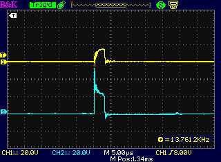
 The "+" side of the drive (a) from the motor
controller and (b) following
The "+" side of the drive (a) from the motor
controller and (b) following
the diode at the unit's coil, with the diode the right way around:
Essentially the same less a diode drop (< 1 V)
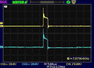
 The "-" drive, and at the coil on the "+" side
following the diode, which was in backward.
The "-" drive, and at the coil on the "+" side
following the diode, which was in backward.
That's the only time a coil spike was seen, but it was at the wrong
time and with little energy.
(I'm not sure why a timing offset is seen. It seemes to be just in this
one trace.)
Okay, for someone trying to do groundbreaking work, I sure
made a lot of stupid mistakes. All a learning curve! I always take
comfort in what Roger the plumber said to me in about 1995: "The only
people who never make mistakes are the ones who never do anything."
So. Even with isolation diodes, was it possible to drive
the coil so that the turn-off spike wouldn't be damped off? It didn't
look like it. Maybe with a capacitor in series? Nothing like a tuned
circuit to maximize an oscillation! Time to refresh my memory of that
aspect of circuit design from BCIT in 1975. But it would have to wait
until
after Christmas.
The circuit... what circuit?
I had already been
thinking about and working on a pulse generator.
On the 18th and 19th I
spent some hours doing the revised circuit board for a microcontroller
based pulse generator. I printed out the finished board deign, then I
started thinking that the whole thing was pretty simple. While an LCD
display showing all sorts of info would be cool, why not just use a
couple of simple chips and forget the microcontroller? That would make
it much easier for others to duplicate and eliminate the need for
programming The programming requirement would add a level of complexity
beyond the grasp of many DIY builders. OTOH, for the prototype, the
easier it was to see what was going on, and the more the adjustments
and operating parameter possibilities it had, the more the things that
could be tried out simply by changing the programming instead of having
to modify circuits.
So the prototype should be run by microcontorller, and
doing the circuit hadn't been a waste of time. (Whew!) Once optimum
performance was obtained, a dedicated circuit could be created.
How to do a dedicated hardware circuit? Feedback would be
the filtered DC output voltage. That, after all, is the desired result.
One could modulate the pulse widths manually easily enough using a 555
timer and a potentiometer. But how to do it from voltage feedback? No
doubt it could be done.
But perhaps even that is a needless level of complexity.
It could be even simpler: If the voltage was below the setpoint, there
would be pulses. If it was above, there wouldn't. So: a 556 dual timer
providing the 60 Hz and narrow high frequency pulses, and an LM339 quad
voltage comparitor turning that on or off. But how to gate the pulses?
Use a second and third comparitor on the LM339 as switches to gate the
signals from the 556? Or add a CMOS logic triple 3 input AND gate: Low
frequency is high AND high frequency pluse is high AND voltage is below
setpoint will send the pulse to the coil driver. Or something like that.
I decided to continue using the car motor controller until
and unless I got some results. The idea of a tuned resonant circuit, if
it worked, or perhaps some other idea, might necessitate more changes
to the design, so I would wait.
Rechargeable Battery Making
... NOT with oxalate electrolyte?
As the battery performance
deteriorated, I started thinking it must be the zinc electrode that was
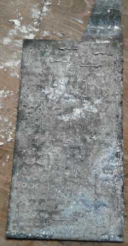
the problem. But how could that be? I looked at the old one. The
connection tab seemed almost
ready to break off where it came out of the case. With a little
touching, it did. This was something I has also noted with the
nickel-manganese cell negative electrodes with zinc current collectors:
where they
were not in contact with the Mn powder, they deteriorated and I ended
up switching to graphite current collectors. I didn't think it would
happen since I wasn't pushing it up to the -Mn (metallic) voltage. But
there it was.
I suspected it had something to do with hydrogen gas
bubbling off, but there are no electrochemical reactions shown to
combine zinc with hydrogen. Some reading on line on the 10th disclosed
that in flooded nickel-iron batteries, both the nickel hydroxide and
the iron absorb a large amount of hydrogen over the life of the
battery. In fact, the nickel hydroxide absorbed up to 22 wt% - four
times as much as a 2015 "target to aim for" for hydride storage. The
problem with using them as hydrides is they don't release the H atoms
under normal operating conditions. Surely then zinc electrodes will
also absorb hydrogen - and apparently in doing so become brittle and
break.
A big part of the problem is doubtless that I put in
charged (metallic) zinc and probably quite discharged MnO2 (Mn2O3,
MnOOH...). So as the MnO2 side charges (or is it to Mn(C2O4)2 in
oxalate?), the zinc side merely bubbles
hydrogen. I didn't think it could be absorbing it because there were no
electrochemical reactions shown for it, but turning it into a hydride
is what
these relatively new papers seemed to suggest. The second electrode
wasn't (yet) as brittle as the first one.
 So my next
endeavor was to put 12 grams of yellowish ZnO
powder, which needs to be charged to Zn metal, into the (2nd) zinc
electrode. Another consideration was that my ultra-fine zinc (metal)
powder, at least the "flakes" jar, seemed to be so densely packed that
it kept electrolyte out and didn't work well. By putting in ZnO, when
it charged to Zn, there should be some spaces left over between the
zinc atoms for the water. At least, with little knowledge of
crystallography or how atoms behave, that was my theory.
So my next
endeavor was to put 12 grams of yellowish ZnO
powder, which needs to be charged to Zn metal, into the (2nd) zinc
electrode. Another consideration was that my ultra-fine zinc (metal)
powder, at least the "flakes" jar, seemed to be so densely packed that
it kept electrolyte out and didn't work well. By putting in ZnO, when
it charged to Zn, there should be some spaces left over between the
zinc atoms for the water. At least, with little knowledge of
crystallography or how atoms behave, that was my theory.
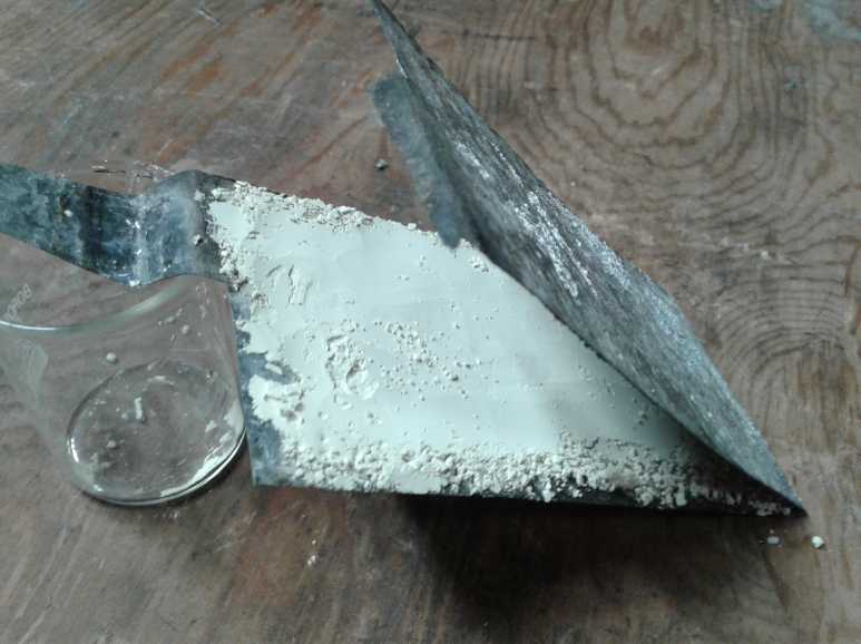
I sprinkled in the powder and smoothed it off with a
teaspoon.
 Then I pressed
the electrode closed, then I put in ordinary
staples. It was tough going, but they went in. If I had used the
heavier staple gun, say with cardboard behind, I'd have had to bend all
the staple ends over. Finally I took a hammer and pounded the staples
flat anyway, which pretty much put some momentary pressure all across
the
electrode to compact the powder.
Then I pressed
the electrode closed, then I put in ordinary
staples. It was tough going, but they went in. If I had used the
heavier staple gun, say with cardboard behind, I'd have had to bend all
the staple ends over. Finally I took a hammer and pounded the staples
flat anyway, which pretty much put some momentary pressure all across
the
electrode to compact the powder.
12 grams of zinc oxide is 820 AH/Kg * (65.4 / (65.4+16.0)) = 7.9
AH theoretical capacity. Add to that the capacity of the degraded sheet
zinc itself? Surely over actual 10 amp-hours? A second electrode would
probably
be needed to get it up to 20 or 25 to match the plus side.
It was soon charging at 120
mA. Same sort of low currents
as before. I decided it was time to try some sodium oxalate to see if
that would help boost things. I combined some oxalic acid with some
sodium hydroxide. (I left it a little acidic in preference to having
free sodium hydroxide.)
It still had low currents, and it still had the same sort
of high self discharge as all my cells of any chemistry have always
had. Nothing I try seems to fix it. Why can any commercially made cell
sit there and hold its charge, but all mine bleed off? I have some
theoretically great stuff, all going to waste because I can't actually
say to anyone "Here's a great battery that will work well." What, what
am I doing wrong?
"In theory, there's no difference between theory and practice. In
practice, there's a great difference." - (I forget who said that).
Manganese-Metal Hydride cells?
 A
thought occured to me... Sometimes my cells have quite a
few amp-hours but usually at voltages below a volt. Could that be from
hydrogen storage rather than from the chemical reactions I was
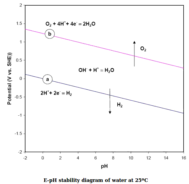
expecting? MnO2 at pH 12 is only +.25 volts. Hydride at pH 14 is -.833
volts, and less at lower pHes. Found a Pourbaix diagram for just water:
it's around -.72 volts at pH 12. So +.25 - -.72 = .97 volts.
Hmm!!! A manganese-metal hydride cell, with zinc as the hydride? How
much hydrogen would zinc store? Or should I say, how much hydrogen
would zinc oxide store, since zinc would convert to its oxide form (or
oxalate) at such a low voltage and stay there. If the corrosion of the
zinc sheet metal is an indication, it either holds a lot, or is easily
subject to weakening by hydrogen infusion.
A
thought occured to me... Sometimes my cells have quite a
few amp-hours but usually at voltages below a volt. Could that be from
hydrogen storage rather than from the chemical reactions I was
expecting? MnO2 at pH 12 is only +.25 volts. Hydride at pH 14 is -.833
volts, and less at lower pHes. Found a Pourbaix diagram for just water:
it's around -.72 volts at pH 12. So +.25 - -.72 = .97 volts.
Hmm!!! A manganese-metal hydride cell, with zinc as the hydride? How
much hydrogen would zinc store? Or should I say, how much hydrogen
would zinc oxide store, since zinc would convert to its oxide form (or
oxalate) at such a low voltage and stay there. If the corrosion of the
zinc sheet metal is an indication, it either holds a lot, or is easily
subject to weakening by hydrogen infusion.
Then I looked up, specifically, "zinc hydride".
Unmentioned in the electrochemical charts, zinc will form a white
powdery compound, ZnH2, in the presence of hydrogen gas. As I
say, I
had previously looked
to make sure it didn't, and it wasn't shown the electrochemical charts.
They didn't include gas.
This is probably what I've
been missing, or at least is something I've missed seeing all this
time. I
mistook the white powder for zinc oxide - and vaguely wondered why it
didn't seem to all charge to metal with all the charging.
Of course, if it was so easy to make a hydride that would
work well in a battery with something as common as zinc, it probably
(but never say never!) would have been found years if not decades ago.
Of course it would be a problem
that it needed H2 gas to make the hydride rather than splitting water
into H+ : OH- ions and absorbing the H+. And it said ZnH2 "gradually"
decomposed into Zn metal and H2 gas - or very quickly in acid. It
might not come out "on demand" when one wanted electricity, and
especially not by turning OH- ions into H2O. (But it means all I have
to do is wait to decontaminate the electrodes. How long? Also the H2
comes out "quickly" at over 90°C. I set it on the woodstove for
some hours.)
Single use cells don't have the hydride problem because
the
hydrogen is only formed during charging. And in a
rechargeable cell, if the zinc isn't overcharged, the gas won't form
and the problem won't occur. In trying to charge the MnO2, I've been
overcharging the zinc and it bubbles hydrogen. Apparently I need to
charge the MnO2
electrode before it's put into the cell, so that both electrodes are
already charged when starting. Then, it needs to be positive limited so
that the positive side bubbles oxygen before the negative side bubbles
hydrogen. When that happens, as in NiMH and NiCd dry cells, the oxygen
finds its way to the negative electrode and causes discharge, so that
hydrogen is never formed. The reason given is that hydrogen gas
pressure would burst the
dry cell. Nobody ever said anything about hydrogen contaminating the
electrode!
New zinc electrodes... Works!
It seemed like a good chance that the hydride accounted
for
the self discharge. So the next thing to do was to make a new zinc
electrode, put it in, and not charge it. The MnO2/Mn(C2O4)2
should have
been long since charged unless the hydrogen affected it, too, and the
metallic zinc is already the charged form. So the cell should be full
voltage, should not self discharge, and should work well to run a load
- at least until it's charged.
Before disassembling the cell, I let it sit for the better part
of a day. The voltage dropped to about 1.15 volts, rapidly at first
then more and more gradually. Whether it was still dropping very very
slowly or not I don't know because that's when I took it apart, but
that particular voltage acquires significance below.
I made 2 zinc electrodes on the 14th, just single sheets
of zinc, sanded to roughen the surface and etched for micro roughness.
(Then cleaned in solvent to get rid of any chloride remaining from the
ferric chloride.)
I put one on either side of the MnO2 electrode and put it together. I
added a little (more) sodium oxalate. (And I finally remembered to
check the pH. It was about 12, as expected.) The cell read 1.4 volts
and rose over 10 minutes to 1.45. That much seemed promising. Then I
shorted it and the currents were no better than usual. And it took a
while just to come back to 1.2 volts. So I wasn't expecting much.
But I connected the 11 ohm load. As expected, the voltage
went under a volt, to about .97 volts. Unexpectedly it started to rise,
and was soon up to 1.018 volts in a minute. It hit 1.019 and held over
1.018 for over 5 minutes. But it didn't start dropping like on most
trials. Supplying ~91 mA, it stayed up there. It started dropping by
about only 1/2 a millivolt per minute instead of tens of millivolts per
minute. Well, yay! Being pushed down to a volt to drive just 90 mA
didn't say much for current capacity, but for once, finally, something
was
behaving like a battery should!
After a full hour, having delivered 90 mA-hours of current
it was down to .994 volts, just 25 mV below the highest point. It
started at under 1.3 volts before the load was connected, and when
disconnected, it only rose up to 1.152 volts after 10 minutes, so it
couldn't be said it that sourcing 90 mA had dragged it down from a 1.5
volt level.
But why should the voltage be so low? First we can
apparently say it was dragged down about .2(?) volts by the "heavy"
current being drawn. So we might call the essential open circuit
voltage "1.2 volts".
This was fully charged metallic zinc. Either it was ~ -1.2
volts or it wasn't. It must have been. Let us look to the manganese
side, then to see about intermediate voltages.
Reading between graph lines as best I can here are the theoretical
voltages:
MnO2 (+.28 v) - Zn (-1.17 v) = 1.45 V
MnOOH (-.02 v) - Zn = 1.15 V
Mn3O4 (-.27 v) -Zn = .90 V
Mn(OH)2 to Mn(metalic) reaction is more negative than zinc, so Mn(OH)2
wouldn't make a voltage.
If just a few Mn's were charged to MnO2 (Mn valence 4), we
might get the initial 1.45 V, but as soon as any current was drawn,
they would be discharged leaving MnOOH (or Mn2O3; or Mn2(C2O4)3) (Mn
valence 3). 1.15
volts was in fact exactly what was left after the discharge test (after
recovery).
I think it's a pretty safe conclusion then from the
voltages seen that the manganese, in spite of the countless hours of
charging it had with the other zinc electrode, was in the state MnOOH
(or Mn2O3; or Mn2(C2O4)3) rather than MnO2 or Mn(C2O4)2 (ie, Mn valence
3 instead of 4), and that for
some reason that's the state it wanted to stay in rather than charge
further. Putting in a higher voltage forced some of it to charge to
MnO2 but it didn't want to stay there, so it self-discharged to MnOOH
and the voltage wouldn't stay up long at the ~ 1.45 V level.
In fact, in the next discharge test, it continued down
from where it left off after the first one, as if no charging had taken
place.
Why?
Could that have been an effect of the hydrogen? As a gas
it would have entered the positive electrode as much as the negative.
Perhaps at the voltage of MnO2, the H2 combines spontaneously with the
Os to make Mn(OH)2, an overdischarged form that needs to be charged
again. So that's my present theory. If that is so, once again, it will
only happen if the negative electrode is overcharged and bubbling
hydrogen gas.
Another possibility is that it has something to do with
oxalate. If so maybe there's no point trying to charge it higher than
1.15 volts? One good thing is that if it can't charge to valence 4, it
will never charge to permanganate, valence 7, which would eventually
dissolve. OTOH it would be poor if it only moves one electron instead
of two, halfing the amp-hours per gram - and the cell is only
theoretical ~1.15 volts instead of ~1.45. That's a lot less energy.
On the negative side, the zinc would turn into ZnC2O4.
Could there be some problem reversing this reaction too? Or was it just
the plus side?
Oxalate DOESN'T WORK?
So... how do we get the Mn side initially charged up to
MnO2 (or to Mn(C2O4)2?) to match the charged Zn 'trode? I tried looking
it up but found no
useful information. For converting nickel hydroxide into nickel
oxyhydroxide one uses bleach (sodium hypochlorite, NaClO) and I
suspected that would work with manganese too, so I took the cell apart
and put the electrode in bleach solution to try to oxidize it to MnO2
non-electronically. A bit of the powder came out: the gas probably
pushed it out the too large perforations and the cracks around the
edge. Then I saw tiny bubbles coming out for a while. It also started
turning the connection tab blue-green - copper oxide? I had planned to
leave it in overnight, but I didn't want to lose the connection tab, so
I pulled it out, and then rinsed it by putting it in water and changing
the water a few times. (Please, no chloride in the cell!) Hopefully
enough Mn2O3 would have become MnO2 to make the cell a solid 1.45
volts. Then the question was whether that would stay or if the self
discharge would appear and the cell would drop back to 1.15 by itself.
I put the cell back together. It never went above 1.15
volts. Let's see... nickel hydroxide wouldn't charge to oxyhydroxide.
Manganese wouldn't charge to dioxide level (really to Mn(C2O4)2). Maybe
it won't charge at all? I
was reluctantly forced to the
conclusion that oxalate was somehow forcing the voltage down to where
substances won't charge. For all the seeming advantages, it just wasn't
working.
But I could try sodium oxalate again - ether by itself as
the main electrolyte, or else as a
"catalyst" for the potassium oxalate, noting how sodium (as
sodium-hydrogen sulfate) helps get
lead-acid batteries to charge better by getting the sulfate off the
plates. Might it help get oxalate out of the zinc electrodes? Or might
it help get oxalate into the Mn electrode? It's not very soluble, but
it's 20 times more so than just calcium hydroxide, so I won't give up
on oxalate without a bit more experimentation. (I ordered some on
January 5th as I edited this. That way I know I can
trust the quality. I had been wanting to for some time, but hoped to
put the order off until I wanted another chemical or two as well. I
still hadn't thought of any, but I finally broke down and ordered a
microscope too. It was the cheapest one and I hope it's half decent. By
"Coulter Optical" - the same outfit that made my low cost 10" reflector
telescope about 3 decades ago. That had very good optics.)
A final thought occurs to me: It's eay to convert between
HOH and OH- ions in KOH solution. A reaction can use or create a bit of
water, which is balanced overall, and perhaps in initial charging some
hydrogen or oxygen bubbles off to attain the balance. With K2C2O4, if a
C2O4-- ion is absorbed into an electrode with none released by the
other electrode, it leaves two free K+ ions, which will no doubt
convert with water to 2 KOH and release hydrogen as H2. Maybe I have to
convert the MnO2 into Mn(C2O4)2 initially before it's put into the
cell? Otherwise, what about the extra potassium when its C2O4-- is
absorbed into the plus electrode during charging? Is that why it won't
charge?
If I'm using Ca(OH)2, what about using CaC2O4? so any left
over Ca can become more Ca(OH)2? Oh ya... CaC2O4 isn't soluble.
Insoluble? Egads... does that mean one could use CaC2O4
<==> Ca(C2O4)2 as a positive electrode substance?... or is the
voltage (+1.55 V) too high?... What about in ethaline DES?... or is
Ca(C2O4)2 an insulator?
(Wild possibilities are multiplying... Egads, how did I get started
doing chemistry?... oh ya... for better batteries!)
JUST Calcium Hydroxide Electrolyte?
Something occurred to me that I should probably have
tried
long, long ago. Just calcium hydroxide for electrolyte. It
seemed like a silly idea because it's so insoluble compared to any
other
electrolyte. Here's a table of solubility for
various potential electrolyte substances (grams of substance per 100 mL
of water):
Electrolye
|
Solubility
|
Comment
|
| NH4Cl |
37 |
Std. dry cell - dissolves the zinc
|
| KCl |
34
|
alternative, but also dissolves
|
K2SO4
|
11
|
also dissolves metals
|
K2C2O4
|
36
|
some aspect of this doesn't
seem to be working??? (so far)
|
Na2C2O4
|
3.41
|
electrolyte, or catalyst for above?
|
KOH
|
112
|
Used in all previous alkaline cells:
OH- ions, pH 14 - very caustic
|
| Ca(OH)2 |
0.173
|
OH- ions... but not very soluble!
BUT it makes for pH 12 solution
instead of 14 - much less caustic
|
|
|
Other "alkaline earth"
metal hydroxides:
|
| Mg(OH)2 |
0.000963
|
A.K.A. insoluble
|
| Sr(OH)2 |
1.77
|
no doubt too soluble - pH 13+
|
| Ba(OH)2 |
3.89
|
too soluble - pH 14
|
What does insolubility do? It limits the current capacity. My currents
have been so low anyway, what's the difference? Maybe the oxalate does
nothing useful at all and that's already why the currents are so low?
Other
than that it has real and unique advantages:
1) Zinc, nickel and manganese won't dissolve in it
2) It makes the solution pH 12 instead of pH 14, so zinc doesn't form
that soluble ion that plagues it at pH 14
3) It is virtually bound to work - just like potassium hydroxide -
because
all the ions and reactions are only hydroxide.
Low current batteries that WORK would be much better than high current
batteries that don't work. I would be satisfied with batteries that
need a much larger surface interface area because of slow electrolyte
as long as they actually work, last a very long time, and have very
high energy storage. They would be (as I have been trying to create all
along) an improvement over everything out there.
I suppose a similarly very, very weak solution of
potassium or sodium hydroxide would do much the same thing. But with
calcium a reserve can be included in the cell to replace any that
becomes calcium carbonate. No such reserve is possible with potassium
or sodium. And calcium carbonate (rock) isn't soluble, so it exits the
solution (lodging in an electrode somewhere, no doubt). Unless the top
is wide open it should take an age to convert all the spare Ca(OH)2 to
CaCO3. Potassium and sodium carbonate are soluble. The only answer for
them would be to change the electrolyte, as is in fact occasionally
done with flooded Ni-Fe (etc) alkaline cells.
Now... did I need to make new electrodes because the old
ones were contaminated with oxalate, or could they be cleaned out?
Perhaps it could be dissolved out in... hmm, gasoline? That was the
first thing to try (17th, AM)
I suspect that with just Ca(OH)2 electrolyte, I could go
back to using higher voltage nickel for the plus side. Ni-Zn would be
highest energy voltage and energy (cars); Mn-Zn would surely be
cheapest overall (on-grid or off-grid energy storage). (And then
there's Ni-Mn or Mn-Mn?)
Later I checked out the other "alkaline earth" elements:
magnesium, strontium, barium and radium
hydroxides. (No figure was given for radium hydroxide in Wikipedia's
table. I wouldn't have wanted to use it anyway.) No others were
close to calcium. Mg(OH)2 was insoluble and the others apparently at
least somewhat too soluble. They'd
have made it pH 14 or very close to it, and so seemed to have no
advantage over KOH. Ca(OH)2
was the one suitable one.
On-Grid Energy Storage?
It's one thing to speak of storage by water reservoir
above a hydro
generator to provide electricity for weeks and months. It's quite
another to speak of a few hours storage just to smooth out intermittent
natural energy sources and daily load fluctuations to avoid turning
(eg) a diesel generator on
and off as loads and intermittent renewable power sources come on and
off line.
Pumping water to a storage tank on a hill to run a hydro
generator might work well
for that. But could a horde of inexpensive Mn-Zn oxalate batteries
accomplish that job too, probably more efficiently and for a lower
price? This is a major potential use if they can be made to work.
http://www.TurquoiseEnergy.com
Haida Gwaii, BC Canada