Turquoise Energy Ltd. News #2^7 (= #128)
covering
January 2019 (Posted February 1st 2019)
Lawnhill BC Canada
by Craig Carmichael
www.TurquoiseEnergy.com
= www.ElectricCaik.com
= www.ElectricHubcap.com
= www.ElectricWeel.com
Month
In Brief
(Project Summaries etc.)
- Battery Project - When EV's were "Killed" - Carmichael Mill -
Lumber Cutting - Ground Effect Vehicle Improvement? - Expanding my
Solar Power System - NO Tidal Power project
In
Passing
(Miscellaneous topics, editorial comments & opinionated rants)
- World's Most Costly Garbage Pickup Service? - Sardine Tins and
Bathtub Designs - Clinton & the "Deep State" - Why They
REALLY DON'T Want the US-Mexico Border Wall - Yellowstone
Volcano: ready, set, ...? - Coming Collapse:
Contempt & Disdain - Cryptocurrency Exchange Failure? - ESD
(Eccentric Silliness Dept.)
- Project Reports
-
Electric
Transport - Electric Hubcap Motor Systems
* Ground Effect Vehicle - New wing profile & restart of design -
Trying out RC components
Other "Green"
Electric Equipment Projects
* Carmichael Mill ("Bandsaw Alaska Mill")
* Mining Beach Sand?
Electricity Generation
* Expanding My Solar Power System - grid ties - 36 volt DC LED lights -
Solar Hot Water? - Batery consreving controls? - Putting up some of the
New Solar PV Panels
* Magnetic Flipping HE Ray Energy?
* Woodstove Thermoelectric Generators (TEGs) (Didn't get very far...)
Electricity Storage -
Turquoise Battery
Project (Mn-Zn, Ni-Zn or Pb-Zn in Oxalate Methyl
Hydroxide electrolyte)
* Experiments mostly with Mn-Zn... - Attempts by Others to use Zinc -
Oxalate Electrolyte or Not? - Lead-Zinc in Oxalate (with commercial
lead oxide electrode plates) Again (Jan 9th - Aborted) - Totally Common
Ingredients!?! New Mn-Zn Cell With Very Weak Potassium Hydroxide - Was
it the Water? - Thicker KOH Electrolyte: Finding Solutions - Sodium
Oxalate - Alcohol: Methyl Hydroxide - Proton Membranes
New Chemie Batteries
I spent a lot of time on battery experiments and research
this month. Too much! It took time away from everything else. I've
always just wanted some simple to make, lower cost, long life
batteries. Of course, so does everybody else and no such "ideal"
batteries have appeared
in over two centuries of battery research. There
are a lot of elusive "almosts" and short cycle life solutions. After
all this time and with all the ideas I've had, nothing I've done has
actually made any that have been practical.
This month new ideas were suddenly springing up left and
right, and my only sure conclusions are that what I've tried so far
hasn't worked out... and that in some ways I'm still out of my depth. I
keep finding out about things that that have been causing me unknown
problems that others already know.
Oxalate electrolyte didn't seem to work like I had confidently expected
it would.
It all got rather discouraging.
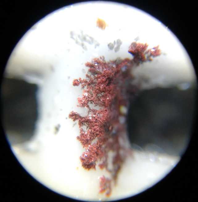
Copper dendrites shorting
out the cell across the separator grille, under the microscope
 One especially bright spot was a "new" hydroxide electrolyte I
somehow found but glossed over and forgot a decade ago. Hydroxides seem
to be what really work
best and don't dissolve electrode substances - except especially zinc,
which gives
the best energy and conductivity but gradually dissolves during
discharge at the pH 14 of the hydroxide electrolytes. But the
organic substance methyl hydroxide, CH3OH - AKA methanol,
AKA wood alcohol,
AKA methyl hydrate, AKA methyl alcohol (I think all the names confused
me) - is a soluble hydroxide that is (evidently) mildly acidic instead
of pH
14. By mixing that with a small amount of pH 14 hydroxide, one should,
presumably, be able to get a hydroxide electrolyte of any desired pH. I
ordered some from Westlab.com. Then I realized I already had some,
hardware store variety, that (IIRC) my mother gave me about 40 years
ago and I didn't know what to use it for. On my first try I didn't use
enough KOH and it was apparently too acidic. On recharging the
electrodes shorted out with both copper and zinc dendrites. These were
clearly visible under my new microscope, a valuable piece of equipment
I should have bought long ago.
One especially bright spot was a "new" hydroxide electrolyte I
somehow found but glossed over and forgot a decade ago. Hydroxides seem
to be what really work
best and don't dissolve electrode substances - except especially zinc,
which gives
the best energy and conductivity but gradually dissolves during
discharge at the pH 14 of the hydroxide electrolytes. But the
organic substance methyl hydroxide, CH3OH - AKA methanol,
AKA wood alcohol,
AKA methyl hydrate, AKA methyl alcohol (I think all the names confused
me) - is a soluble hydroxide that is (evidently) mildly acidic instead
of pH
14. By mixing that with a small amount of pH 14 hydroxide, one should,
presumably, be able to get a hydroxide electrolyte of any desired pH. I
ordered some from Westlab.com. Then I realized I already had some,
hardware store variety, that (IIRC) my mother gave me about 40 years
ago and I didn't know what to use it for. On my first try I didn't use
enough KOH and it was apparently too acidic. On recharging the
electrodes shorted out with both copper and zinc dendrites. These were
clearly visible under my new microscope, a valuable piece of equipment
I should have bought long ago.
Another potential improvement was nafion ion selective
membrane. This lets hydrogen ions - protons - pass through but not much
else. It might be used to prevent dissolved ions from passing from one
electrode to the other, and would potentially allow having one
electrolyte for
the plus electrode and another for the minus. Costly as it is, I
ordered a piece of that, too. Then I found that attaching it so nothing
gets around the edges has its own set of challenges, usually involving
barium metasilicate.
When EV's were "Killed" (not for the first time)
 Many will recall the
documentary Who Killed the Electric Car, about
the GM EV-1 produced in the late 1990s, which was an exciting electric
car with the nickel-metal hydride flooded batteries that were such a
huge advance over lead-acids. (It was some years before more recent
cars with lithium batteries equalled its driving range capacity.)
Many will recall the
documentary Who Killed the Electric Car, about
the GM EV-1 produced in the late 1990s, which was an exciting electric
car with the nickel-metal hydride flooded batteries that were such a
huge advance over lead-acids. (It was some years before more recent
cars with lithium batteries equalled its driving range capacity.)
At the same time other car companies made
some very nice electric vehicles, most of which were likewise only
leased and
not sold, and were crushed when the greedy got control over the
California
government and had the mandates for clean cars repealed. One exception
was the Toyota RAV-4 EV. Some of those were sold. Of course, once
Chevron was given control of the batteries, it became impossible to get
replacements. But many of the flooded NiMH batteries still work
passably well, or did until fairly recently and some may just need the
electrolyte replaced.
A friend in Victoria BC, Eric, got together with someone
else and
they have now brought up from California and put together two revamped
RAV-4 EVs from about 1996 to 2001 with batteries from three,
re-outfitting
them to plug into today's charging stations.
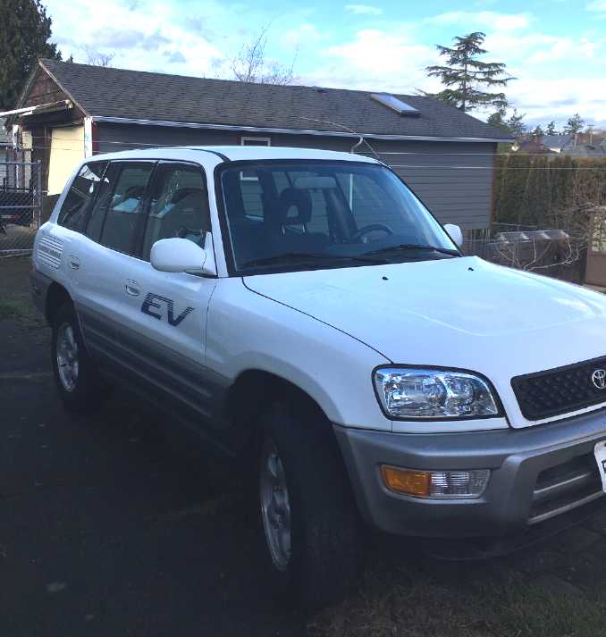
Here is Eric's beautiful
"new" 2001 RAV-4 EV, always kept in a garage in California. It had a
remaining range of just 5 miles, but is
being outfitted with refurbished NiMH cells to bring it back to 100(?)
miles.
...Not bad for 500$US! (Well... plus substantially more than that for
shipping.)
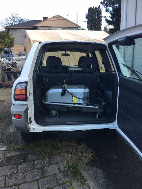 In the back is the original charger.
Carmichael Mill - Lumber Cutting
The handheld bandmill is basically finished and continues
to perform
well. I uncovered - and fixed on the lathe - a minor problem with the
guide wheels being a little too wide, which caused them to gradually
pinch the "set" off of the inner teeth and cause "cupped" and wavy
cutting.
The biggest news for me was that I finished milling up the
big cants of spruce that were blocking my driveway, except one that I'm
saving. After
some clean-up I drove the Leaf through the previously blocked space for
the first time since summer 2017.
When the last cant is gone (or shoved off farther to the side after
some more clean-up of branch piles that were formerly trapped
underneath the cants of wood), I'll have back the whole circle driveway
that came with the house before I had the trees cut down! Yay!
But I've still only cut up half of the spruce - the rest
just isn't blocking the driveway.
Ground Effect Vehicle Improvement?
 I watched a
video of a model ground effect craft. It was
very short, of a primitive model launched across the floor by a rubber
band, but it got my attention. Like some others it was "catamaran" in
form, but the wing profile seemed unusual. (The closest thing I've seen
to this
profile - and not very close - was something called the "Flugboat"
which can also be found on youtube.) The maker explained to me that the
unusual shape shifted the wingtop "vacuum" lift toward the rear of the
wing, while the ground effect "compression" lift underneath was
greatest at the front. Since only the ground effect lift decreases with
altitude, this profile gives the longitudinal "level flight" stability
for the craft to find its optimum altitude and attitude based on the
speed and
weight, without the lower lift and high attack angles of the Bixel flat
wing that required extra high takeoff speeds. It *might* not even need
a controlled elevator. The bottom is actually pretty flat. It's the top
shape that is novel.
I watched a
video of a model ground effect craft. It was
very short, of a primitive model launched across the floor by a rubber
band, but it got my attention. Like some others it was "catamaran" in
form, but the wing profile seemed unusual. (The closest thing I've seen
to this
profile - and not very close - was something called the "Flugboat"
which can also be found on youtube.) The maker explained to me that the
unusual shape shifted the wingtop "vacuum" lift toward the rear of the
wing, while the ground effect "compression" lift underneath was
greatest at the front. Since only the ground effect lift decreases with
altitude, this profile gives the longitudinal "level flight" stability
for the craft to find its optimum altitude and attitude based on the
speed and
weight, without the lower lift and high attack angles of the Bixel flat
wing that required extra high takeoff speeds. It *might* not even need
a controlled elevator. The bottom is actually pretty flat. It's the top
shape that is novel.
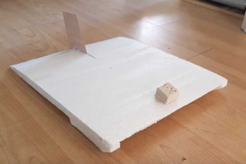
It seems like a brilliant idea. He also had a video of an
earlier radio controlled model ground effect craft with a "regular"
wing design. He doubtless found it unsatisfactory and that led him to
come up with this new wing profile. (Below: Front is at the left.) One
can visualize that, if it wasn't in ground effect range, the back of
the wing would want to lift and aim it down.

Come to think of it, this would be a rather similar effect
to the "wingfish" with its "inverted delta" wing shape and a separate
elevator high up. But this form allows the catamaran design with better
lift-to-drag potential owing to the hulls virtually eliminating wing
& elevator tip vortices. The catamaran shape will surely also be
much
easier to dock at a wharf than something with a fragile wing sticking
out both sides.
With this one last item seemingly solved in a more
satisfactory way than I had found earlier, I started working on the
design of the model again. And I got out the radio control components
and tried them out for the first time. Except for the ducted fan
propeller rubbing a bit on the duct housing (the motor and the fan
weren't made to mount together) and unsatisfactory "backward" control
of the throttle, it seemed to work well.
Expanding my Solar Power System
After initially installing the "off-grid" power system in
the December power outage, I gave it some more thought this month, and
did a bit more on it. Two panels seemed to be enough for that as I was
using it - mostly just for one light - and I moved two of the panels
back onto one of the grid tie inverters.
I want to make the 36-40 volt house wiring system. I
ordered various LED lights and LED emitters to make 36 volt lights with
- mostly 12 volt emitters in sets of three. I ordered several varieties
of 12 volt "cob" lights, a set of three 30 x 60 cm flat panels, and
some screw-in "bulbs" that are supposed to work from 12 to 72 VDC
instead of 120 VAC. They're all on their way on the slow boat from
China.
I gave some thought to a kitchen solar or solar assisted
water heating system (it takes much too long to get hot water in my
kitchen), and controls to run things when the sun is out but shut off
if draining battery power, or if the batteries are getting low.
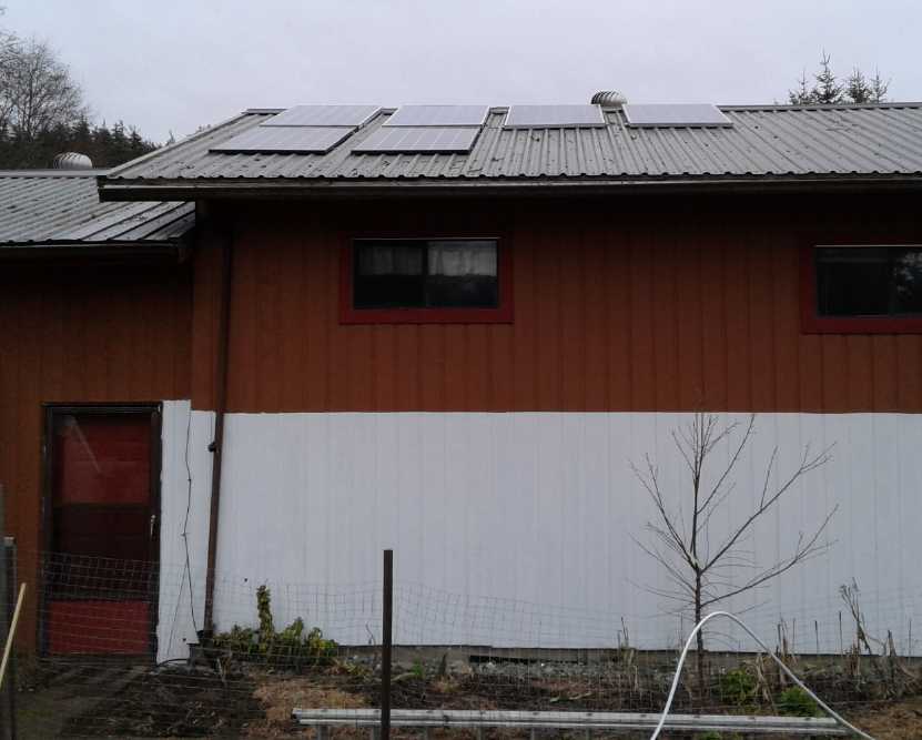 On the 29th
and 30th I put up and ran wires to two of the new 305 watt panels that
are supposed to be better in low light. I hooked them to the other
grid-tie inverter. Performance in the clouds, mist and drizzle was been
poor, but on February first the sun made an appearance and at one point
the two panels ("610 watts") were giving about 270 watts - about all
one might expect from the low angle of the winter sun. They will
improve bit by bit until they're somewhere near their full rated power
in the summer.
On the 29th
and 30th I put up and ran wires to two of the new 305 watt panels that
are supposed to be better in low light. I hooked them to the other
grid-tie inverter. Performance in the clouds, mist and drizzle was been
poor, but on February first the sun made an appearance and at one point
the two panels ("610 watts") were giving about 270 watts - about all
one might expect from the low angle of the winter sun. They will
improve bit by bit until they're somewhere near their full rated power
in the summer.
Doubtless it wouldn't hurt to put up two more.
(The white wall paint is so the garden vegetables get some light
reflected from the north. When it was dark brown they all leaned away
from the house. The wire fence is to keep the deer out of the garden.)
One place that is going
solar in a big way is Puerto Rico. After hurricane Maria power was out
for ages. It's still only been restored in some areas. A whole island
lost its undersea power cable and it's never been reconnected. People
died. Panels and huge battery storage units have proliferated. The
island uses far less petroleum for power now and will never be wholly
without power again. But Puerto Rico gets a lot more sun year round
than Haida Gwaii does in the winter months when power is most needed.
So far what would work best here is tidal power, with the continual
flows churning in and out of long Masset channel between the ocean and
the shallow inland sea.
NO Tidal Power Project
Someone offered to administer a tidal power project if I
wanted to do it - to make the phone calls to look for funding and find
supporters, workers, co-ordinate with BC Hydro, etc. I thought I had
great floating power vessel designs and a great plan to do everything
pretty
much all from shore at low tide, by giving the vessel a "smart" rudder
to position itself into the strongest current (and return to shore when
necessary at high tide for maintenance access at low tide), but having
started working on the ground effect vehicle, somewhere during the
month I decided it was just too much for me to tackle.
Then for a short time I thought
maybe to do just a small 'pilot' or 'private power' project that I
could handle myself without so much outside help, probably to deploy at
the mouth of the Tlell river where there was easiest access to a good
flow. I went to
Coastal Propane, but I hadn't realized their old (free) 80 gallon tanks
were still too big to fit into the car. I could have come back another
time with the trailer, but I finally decided I had better drop tidal
power entirely. It's not that it wouldn't be a great project (and the
small one could put my fine "Improved Piggott" generator to the test),
but I'm already flitting from project to project and getting only bits
done on each one. It needs some other champion to move it forward.
 FloTec (formerly Scot Renewables) latest 2 MW
tidal flow power design.
FloTec (formerly Scot Renewables) latest 2 MW
tidal flow power design.
Their units are helping to power the Orkney Islands off the north coast
of Scotland.
In a few years their units may be for sale globally. In the meantime,
why
can we not make our own - and even play a leading part in a new
industry?
And as usual, I've voiced some opinionated opinions on
various
miscellaneous topics, below.
In Passing
(Miscellaneous topics, editorial comments & opinionated rants)
World's Most
Costly Garbage Pickup Service?
I got a bill in the mail. It was for garbage pickup. I
conserve. I reuse. I recycle. I burn.
What's left goes into the garbage can along with crap I've picked up
off the beach. I take the can out to the road for Thursday pick-up
about once every six weeks or so. I mentioned that to the garbage man,
Paul, in a cafe. He thought for a moment and said "If that." So that's
maybe 7 or 8 cans per year. I would
happily take them to the dump myself on my way by when I need to. The
bill
was for 288$. That's 41$ or 36$ per can - or often half a can.
Yet there it is: a flat rate bill equal to those of careless families
of five who thoughtlessly toss everything they don't want into the
street garbage without
sorting it or worrying that someone else has to deal with their mess,
and who complain that they should be permitted more cans each week.
Why should I be subsidizing the wanton carelessness and
indifference of others? Is that equitable? For the service I get out
of it, I think it's highway robbery. I could buy two or three
garbage cans, per pickup, for that sort of price! It shows a need for
several things:
1. A citizens' social sustainability design team to study the issue and
make recommendations to government. I suspect the following
recommendations will likely be forthcoming:
2. Education of the public about recycling, composting and minimizing
trash.
3. Options for a low basic rate with pay-per-can for anything more than
very
minimal usage. (Others may think of other options, eg, for absentee
owners, who are presently dinged the same high rate for no pickups at
all!)
4. Enforcement of anti-dumping laws. (I can already hear "But people
will just dump their garbage anywhere if they have to pay per can." as
an excuse to not change it.) IF there are offenders, make it
too hazardous for them to dump their trash 'anywhere'. Video cameras
can be set up where such offenses seem to be occurring. Likelihood of
being caught is always the best deterrent. (A decade or two ago, car
thefts
were rampant in BC. Then the police set up "bait cars". After catching
a mere handful of car thieves in a few weeks, the whole epidemic came
to a halt. Either it was all being done by just those few
individuals [probably], or else the arrests scared everyone else off.)
My next door neighbors Stan and Louise spend half the year
in Lac la Hache. They still have to pay the whole 288$ here. And Stan
told
me that in Lac la Hache, there is no fee at all, nor pickup. They take
their garbage to the refuse transfer station, and there is a "swap
table" there where one can pick up anything that looks useful that
others have discarded. (He said Louise sometimes came back with more
than she took!)
What a difference! With very little income and so often
spending so much on R & D materials, suddenly I have to come up
with another 288$, too, but in Lac la Hache I'd have had no problem.
Bathtub Designs
My first question is: Who are all the sadists that create
all the
bathtubs with no slope to the
back end so you can relax in it? The other question is its companion:
Who are all the masochists who buy and install these tubs? Once a tub
is purchased and installed one is stuck with the choice for years or
maybe even a lifetime. (My previous house in Victoria BC still had the
antique cast iron bathtub it came with when I left. That's more than
one lifetime! I soon moved it over to a corner and tiled it in for
showers like any newer bathtub.)
My best guess on the first question is that less thought
goes into a bathtub's design than a tin can's. All those old cast iron
bathtubs from the 1800s at least have sloping backs. The trouble with
them is the thick cast metal is a big heatsink and if you lean back,
your back gets cold even while the water is hot. And of course all the
water cools more quickly. My best guess on the second question is that
contractors build the majority of houses, and they want nothing but the
cheapest - er, I mean the finest - to go into the houses they are
building not to live in but to sell, and again little thought is put
into the tub purchase decision. Or perhaps the contractor may even be
afraid to
put in a tub that might attract notice.
But even examining the cheapness aspect, it is surely
easier to punch out a formed sheet metal bathtub with sloping sides and
ends than straight. We must then go back to the first supposition, that
little thought goes into the design. This hypothesis is reinforced by
them mostly having level, or even (as in my present tub) slightly
convex surrounds. Any water that gets up onto the sill doesn't run back
into the tub as it would if they were, more logically, slightly sloped
inwards. On mine it actually pools up against the wall, and runs down
the outside onto the floor. I finally had to caulk a substantial
silicone ridge "dam" onto the shower curtain side of mine to keep water
from
running around the corner, behind the curtain, and soaking the floor
and bath mat during every shower.
But I somehow get red spots on my legs that seem to be
best treated by immersion for a time in a hot bath, so I don't always
just shower.
Obviously I am never going to divert from my many other
projects to design a bathtub. But I can imagine things I might do or
try if I was in that business. Here are some hypothetical designs - and
things I will look for if I ever have the occasion to be shopping for a
new bathtub... which would probably be because I hate this "typical"
one so much I would like to rip it out and replace it.
1. The aforementioned sloping head end for comfort. It probably doesn't
need to be as sloped as the old cast iron tubs, but enough for
leaning-back comfort.
2. Do they have to be so wide - 24-25" on the inside? It seems to me if
they weren't such big, square tanks it could take a lot less water to
have a bath.
a. First, they might be wide in the middle but taper toward both
ends, say to 18" at the feet and 20" at the head. Maybe even thinner.
Anyway there should be some compromise somewhere between being too
extreme for comfort and using so much water.
b. Vertically, they might be more sloped on the sides as well as
the ends. The 24" or more toward the top might be again say 18" at the
bottom. I've seen a tub with contours - "armrests" - on the sides at
about the high water level, which seemed rather nice.
3. The drain might be at the head end instead of the foot. (in a
corner? or slightly recessed?) That would put the deeper part of the
tub at the head end and it would take substantially less water to cover
to the depth
of the thighs. (If I turn around the "wrong" way in this tub, it's
definitely deeper at my body end; shallower at the toes.)
When the person takes up a higher percentage of the total
volume of the tub, the water will rise up higher when they get in, so
shrinking the volume makes for proportionally more water savings than
than just the reduced cubic tub measurements considered alone would
indicate.
4. Some compromises might be necessary to ensure a good standing area
for showering.
5. Textured non-slip patches on the bottom for safety in the shower
standing area. I've seen a tub with this nice feature in the bottom
enamel. Just enough texture, still not a dirt accumulator. No ugly,
dirt trap rubber mat needed.
6. A "lower entry" area on the outside for best access by the elderly
and the physically handicapped.
Let us be done with these 20th century square "sardine
tin" bathtubs!
Having written this on my old iMac with no WiFi and not
even physically connected to the internet, mind reading Google put up
an ad for
"bathtub inserts" when I was watching youtube on another computer.
Unfortunately this was from a contractor who installs them. I didn't
think much of my chances of getting them up here to do mine for any
sane sort of price (much less getting just what I wanted) and I didn't
follow it up. But I will do a search and see just what "bathtub
inserts" might be
available.
Clinton &
the "Deep State"
I understand Hillary Clinton said this month "If I'm
indicted there'll be civil war." Would an innocent person not have said
something more like "Good! Let them indict me, I've done nothing wrong
and it will at last clear my name."? So we can seemingly read into her
statement, petulant defiance, a threat and an implicit admission of
having willful and significant wrongdoing.
I'm not much worried by the threat. If she had been
indicted a year or more ago while her cronies - who were also Bush's
and Obama's cronies - were still running the FBI, the CIA, the DOJ and
the supreme court and when the public understood almost nothing of what
sort of
entrenched cabal they were being run by, this could have been a
potential. Not now.
"The Most Highs rule in the affairs of men." - Bible. Or as the
Urantia Book puts it, They rule in the affairs of nations. We live in a
time of a great moral and spiritual awakening, which, we trust, will
not be
permitted to be extinguished and delayed by a new dark age.
"Better a deplorable than a despicable." - me
And how is it that so many people, known very bad actors
of various ilks, walk freely, while president Trump's team members are
indicted one after another? According to attorney Harvey Silverglate in
his book Three Felonies a Day: How the Feds Target the Innocent,
there
are
so
many
laws
that
everyone
over
the age of 18 unknowingly
commits around three felonies a day against laws they were unaware of
such as "Dogs within 200 feet of a federal building must be on a leash
six feet or shorter". Did you dig a hole in your back yard without
complying with some EPA requirement? There are over 5 million felony
laws - no one can count them all. No one over age 18 hasn't violated
some of them. There is no requirement that you had to have willfully
and knowingly violated a law with evil intent. "Aha! You forgot to fill
in this box on your income tax form in 2012 - and we don't like you -
so you're going to jail for income tax fraud." On the other hand, the
"deep state" and connected actors, mostly all as criminal as each
other, simply choose not to prosecute each other, even for murder,
theft of billions, child sex trafficking and "crimes against humanity".
Working for president Trump is in their minds the real crime - or at
least the real threat - because he's trying to "drain their swamp".
Here's another Churchill quote: "If there were 20,000 laws, people
would lose their respect for the law." Now it's more a case of "the
law" has no respect for the people.
Why They
REALLY DON'T Want the US-Mexico Border Wall
Finally I think I understand. I watched a video, but it
was the
comments from a viewer underneath that finally told a story that fits
the facts and explains the seemingly absurd obstinacy of the
opposition.
"Follow the money."
The wall, a one-time expense, will cost 5 billion dollars
(or whatever).
Of course we'd all love to have that much money, but it's pocket change
compared for example to what the US spends on
"foreign aid" each year. What it's also pocket change compared to is
200 billion dollars of drug smuggling and who knows how many tens or
hundreds
of billions in human trafficking annually. With a border wall, all this
illicit commerce will doubtless suddenly become far more difficult and
will
surely be drastically curtailed. Where will all the untraceable money
come from for all
the secret "black ops" and unregulated "deep state" activities that
congress has no oversight or control over?
from USAWatchdog.com (Greg
Hunter)
 Those now
opposing the wall gave it lip service in the
past, saying one was needed and actually voting for it, but in fact
doing nothing. Now that one is actually to be built, the same
hypocrites
are dead set against it. Truly they
don't care beans about floods of
illegal immigrants destabilizing the country and destroying its quality
of life, and that these have to be supported
by broke taxpayers or take their jobs, or about the immigrants
themselves -- or much about any societal consequences to anyone. As
long
as their institutionalized cash machine continues to function and fund
their dark budgets, they will let the country rot. The CIA truly is the
Cocaine Importing Agency of
the "deep state". The wall is surely a fundamental threat to the whole
unelected,
underground, shadow government whose tentacles wrap around the entire
US political machine. So is withdrawal from Afghanistan, where the
opium comes from.
Those now
opposing the wall gave it lip service in the
past, saying one was needed and actually voting for it, but in fact
doing nothing. Now that one is actually to be built, the same
hypocrites
are dead set against it. Truly they
don't care beans about floods of
illegal immigrants destabilizing the country and destroying its quality
of life, and that these have to be supported
by broke taxpayers or take their jobs, or about the immigrants
themselves -- or much about any societal consequences to anyone. As
long
as their institutionalized cash machine continues to function and fund
their dark budgets, they will let the country rot. The CIA truly is the
Cocaine Importing Agency of
the "deep state". The wall is surely a fundamental threat to the whole
unelected,
underground, shadow government whose tentacles wrap around the entire
US political machine. So is withdrawal from Afghanistan, where the
opium comes from.
Also: Along with a good majority of all
in border states, lots of Latino citizens in the USA, whether their
ancestors got there legally or illegally, support having the wall.
With the organized
migrant caravans stopped south of the
US border at this time, it appears many Mexicans too, especially
businesses, are getting
fed up with their presence and their needs harming the economic life of
their communities. Perhaps they too will want a wall on their southern
border? It would be shorter.
Today's caravans of thousands will soon become migrations
of millions as conditions worsen. North America will lose its educated
society, culture and civilization and become a chaotic mess if the
process is permitted to proceed unabated.
And if the USA would stop sabotaging South and Central American
affairs, there would surely be fewer migrants whose lives and
livelihoods have been trashed, who flee to try and find a decent life.
The campaign to destroy Venezuela in order to get them to virtually
hand over their oil fields
to American interests for free is disgraceful. The deplorable situation
in Venezuela largely came about through US sanctions and seizure of
Venezuela's funds. (Funny we hear no sympathetic calls to donate to aid
the
poor, starving Venezuelans.) Instead 20 billion dollars of "aid" is to
go to try to overthrow Maduro and install some dictatorship
more to America's liking.
Yellowstone
Volcano: ready, set, ...?
Many have said, and have said for some lifetimes, that the
chance of the giant Yellowstone volcano going off "in our lifetimes" is
trivial. Given that last major eruption was 600,000 years ago, this
seems like an awfully safe bet. But then its big
eruptions have been at 600,000 year intervals. At the other end of the
spectrum are those observing it like Mary Greeley (youtube), mostly
since mid 2018, saying that it looks like it's going to go off very
soon. The ground has been bulging up, geysers have become more active
and there are new ones, and some have started spewing rocks as well as
steam. And there have been some earthquake swarms - which were the last
signs before Mount Saint Helens erupted in 1980. So much sulfur dioxide
is coming out of the ground it's killing the forests around the caldera.
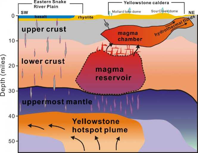 If the Yellowstone "supervolcano", with a caldera 35 by 45
miles, did blow in a major eruption, it would dwarf Mt. St. Helens. The
more excitable have said that the ash cloud would "destroy the United
States", "make humans extinct", or at least cause the economy to crash.
It is certain there would be vast disruptions to transport, deliveries
and food production in North America - especially to air travel and
possibly for two or three or
four years. More locally lava and pyroclastic flows could devastate
- bury - vast areas up to 100 or 125 miles away. I am very glad I don't
live in
that "kill" zone.
If the Yellowstone "supervolcano", with a caldera 35 by 45
miles, did blow in a major eruption, it would dwarf Mt. St. Helens. The
more excitable have said that the ash cloud would "destroy the United
States", "make humans extinct", or at least cause the economy to crash.
It is certain there would be vast disruptions to transport, deliveries
and food production in North America - especially to air travel and
possibly for two or three or
four years. More locally lava and pyroclastic flows could devastate
- bury - vast areas up to 100 or 125 miles away. I am very glad I don't
live in
that "kill" zone.
We have little experience with such huge volcanoes. One
geologist thought that it might go off with as little as two weeks
notice.
My question is, if people looking at the Yellowstone
seismic
monitors on line and reporting all these signs on youtube and the web,
are we already looking at the warning signs? Geologists were expecting
Mt. St. Helens to erupt, but even so it blew before they thought it
would. How much warning will all those people really have before the
real event, should it occur? If the signs only gradually get stronger
and stronger over the months, will everyone get complacent and ignore
it until it actually goes?
Coming
Collapse: Contempt & Disdain
People have been talking about a collapse for perhaps this
whole decade - apparently prematurely. (Including me.) While things
have been gradually
deteriorating in many ways, nothing monumental has happened to most of
us yet in
the western world. Someone has stated that people have become not
merely complacent, but actually dismissive and contemptuous of the
idea of a
major collapse. With all the predictions that have not - yet - come to
pass, they feel that anything untoward that happens will surely be
papered over by "the
powers that be".
But the economic news looks more and more bleak with polls
suggesting that now over half (58%) of Americans and Canadians are
living paycheque
to paycheque with record levels of debt and no savings to speak of, up
from
40% a year or two ago. Now even seniors are declaring bankruptcy. Plus,
the sea level rises are just getting going with Antarctica now joining
Greenland and starting to melt in earnest, and weather and geological
calamities are growing ever stronger and
more frequent, causing crop losses our heavily populated planet can
hardly
afford which in turn will lead to unaffordable food prices in
the stores if not empty shelves. Diseases are on the rise and some
antibiotic-resistant thing is likely to break
out in our crowded cities and spread around the globe. Humongous
die-offs of every sort of plant and animal species are being reported
daily from all over the world - even Antarctic krill and ocean plankton
are in peril.
All of this ongoing devastation has become so common most
of it
doesn't make the news any more. Many things that are being done that
are unsustainable are drawing toward their inevitable endings. Chris
Martenson [PeakProsperity.com] says collapse is already happening, that
it's a process, not an event.
But there will probably be some climax to
all this - or at least to some "straw that will break the camel's back"
- (Yellowstone erupting might be a fitting climax?) and it's likely
over another decade or two this will become a dramatically
changed world with a lot fewer people in it. That population
reduction will be highly beneficial to those who remain. Gradually the
quality of life will become vastly better, and people will look back
and say "what
went wrong?" and turn their attention from physical sustainability
projects to those that will ensure social sustainability for the future
of the world.
Those who are discerning the signs of the times will be
more ready in many ways, mentally and spiritually as well as
physically, than "couch potatoes" who dismiss it all as "fear porn" and
do nothing. Physically, many have said it's just good insurance to be
prepared
with a food supply, some "redoubt" prepared to go to outside of cities
in case (for example) you hear of a serious disease spreading in yours,
enough gas
always on hand to get there, and hard cash or real silver in hand for
if the banks are off-line or fiat paper notes aren't being accepted any
more. And it's still true as some have said, that it's better to be
prepared years too early than a day too late. Mentally and spiritually,
are we prepared to contribute, to help ourselves and others when times
of great need - and great opportunities for service - arise? We are
living in, surely, the most unique period the world's history will ever
record.
Cryptocurrency
Exchange Failure?
They say not to leave your cryptocurrency on an exchange
because they get hacked. It's much safer in your own wallet. Oops. With
the poor internet service around here I got complacent. I had left
some etherium on the QuadrigaCX.com exchange for quite some time. I
thought occasionally about withdrawing it to my wallet. But I was
having trouble with the wallet, and I kept putting it off. One day I
went onto QuadrigaCX and transferred the majority to my wallet - or at
least I hope I did. (Once I get into my wallet I'll be sure. I seem to
have done something to the password and will probably need to reset
everything to get back in.)
The price of etheriums being way down from where I bought
them, I thought I would "double down" and get some more. Options for
transferring funds from a bank to this exchange had become quite
limited. Perhaps I should have been suspicious.
I got a "prepaid credit card" at the post office. When I
went
back to the exchange the next day it said "site down for maintenance".
It still said that 3 days later, so finally I checked around. It turned
out that the exchange was mostly a one-man show, and the owner had died
unexpectedly in December. Everyone had been unable to withdraw $money
from it since then. His wife doesn't seem to have any idea how to run
it. I may (I pray) have got my etheriums out just in time - not a day
to spare - and the remainder I left on the exchange in case I wanted to
sell some may well be lost. Until then it was a great exchange. All
quite
distressing.
Assets that are nothing but numbers on a computer screen
at a bank can be lost, too. Paypal is a huge outfit, and it doesn't
lend your money out, so it's probably about the safest place to have an
account. But
QuadrigaCX where I've dealt for several years going down without
warning (as far as I knew) certainly took me by surprise.
ESD
(Eccentric Silliness Department)
Here's a quote I should have had for the article on
the BC Referendum
last month, which appeared to suffer from the same contempt and disdain
as the subject of collapse: The first attempt to change things was in
2008
(which "failed" with 59% approval but a mark of 60% required), and
since then people just didn't want to think about it again, good or
bad. The quote:
"The best argument against democracy is a five-minute
conversation with
the average voter." - Winston S. Churchill
---
WARNING: Really bad puns ahead
---
Q: Ding-dong. When does the SHTF?
A: When the bell over the fan has dung.
---
"Have you heard of lamas?"
"Neigh, but I have herd of horses.
"And flock of flying sheep." (Methinks he's telling yarns!)
Sheep of a fleece may flock in peace.
---
Long drives on vacation with my parents and my two brothers, ca.
1968-71:
Dad: "Oh, here's a White Spot. I guess that'll do."
Somehow it never occurred to me back then that there actually were no
restaurants called "Black Spot" or "Brown Spot".
But I can be pretty dense. Once there were several people were at a
table. In introductions one guy said he ran a filling station and
everybody but me immediately understood he was a dentist.
"in depth reports" for
each project are below. I hope they may be useful to anyone who wants
to get into a similar project, to glean ideas for how something
might be done, as well as things that might have been tried or thought
of... and even of how not to do something - why it didn't
work or proved impractical. Sometimes they set out inventive thoughts
almost as they occur - and are the actual organization and elaboration
in writing of those thoughts. They are thus partly a diary and are not
extensively proof-read for literary perfection and consistency before
publication. I hope they add to the body of wisdom for other
researchers and developers to help them find more productive paths and
avoid potential pitfalls.
Electric Transport
Ground Effect
Vehicle
 Youtube put up
another ground effect craft video suggestion. It was just a short 1.5
minute video of a square model launched by rubber band across a floor,
but it got my attention. The wing
profile was different than any other I'd seen. The model
seemed more stable than others, including with different weights placed
on the
nose. (lighter, right; heavier, left below) I ended up in e-mail
contact with the maker, John Ryland of
RylandResearch.co.uk . He seemed to also have some interesting robotics
projects including a fire-fighting robot.
Youtube put up
another ground effect craft video suggestion. It was just a short 1.5
minute video of a square model launched by rubber band across a floor,
but it got my attention. The wing
profile was different than any other I'd seen. The model
seemed more stable than others, including with different weights placed
on the
nose. (lighter, right; heavier, left below) I ended up in e-mail
contact with the maker, John Ryland of
RylandResearch.co.uk . He seemed to also have some interesting robotics
projects including a fire-fighting robot.
 The wing was
designed with the curve on the top side more
evenly distributed front to rear, in fact with more curve toward the
rear instead of the front, so that the center of the vacuum lift
on the top
was more toward the rear of the wing instead of concentrated toward the
front as in most aircraft wings. It almost looked like it had "flaps"
partly extended. This lift is independent of ground
effect. He said the relatively more flat underside kept the ground
effect compression lift underneath, which decreases
with altitude, more toward the front. Thus if the nose rose up, the
front lost [ground effect] lift while the rear maintained its [suction]
lift, which would tend to lower the nose. This should work to keep the
vehicle in more stable, level ground effect flight.
The wing was
designed with the curve on the top side more
evenly distributed front to rear, in fact with more curve toward the
rear instead of the front, so that the center of the vacuum lift
on the top
was more toward the rear of the wing instead of concentrated toward the
front as in most aircraft wings. It almost looked like it had "flaps"
partly extended. This lift is independent of ground
effect. He said the relatively more flat underside kept the ground
effect compression lift underneath, which decreases
with altitude, more toward the front. Thus if the nose rose up, the
front lost [ground effect] lift while the rear maintained its [suction]
lift, which would tend to lower the nose. This should work to keep the
vehicle in more stable, level ground effect flight.
I had been told or had heard that the Bixel flat or
symmetrical wing,
while more stable, needed too high of take-off speeds, and too high an
angle of attack while flying. It seemed to me this new wing profile
might solve or
at least ameliorate the problems, providing stability and more lift at
lower speeds.
In the whole aerodynamic design, the wing profile was the
remaining detail I had been rather uncertain about, and hadn't figured
out a solution for that I was confident would be satisfactory. It
seemed like a good time to draw up the design for the RC model, e-mail
it
to John for comments, and if it
seemed good to both of us, to build the model.
John mentioned that for water take-off it would need a
"step" in the hull. Steps are commonly used in "V" planing hull shapes
to effectively reduce the length of the hull in contact with the water
and hence the drag. They are ubiquitous on water takeoff aircraft. But
should I use them with the narrow but flat bottom hulls I had in mind?
I had thought not, but now I decided that I should: whether flat or "V"
bottoms, a step would still reduce waterline length and hence the drag
once
planing at higher speeds for takeoff. I put a 3" step in the design, 6
feet from the front out of the planned 16 feet overall length. (Scale
to 1/4 size for the model.) Hopefully 3" rise
wasn't going to make much difference to the "hovercraft box" effect --
if that was needed at all. Also I put the back of the wing another few
inches above the bottoms of the hulls - and a little ahead of the
backs. Better, I hoped, that the wing didn't cause drag in the water in
small waves. Also if the elevator was pointed down, it would cover that
space.
I think I'll start by hoping my earlier hovercraft effect
idea with flaps at the front of the wing to make a complete "hovercraft
box" underneath for take-off at low speed isn't
necessary. And why was I actually concerned about that, anyway? First,
there was the reputed high speed needed for take-off of the Bixel flat
wing, ...and almost
subconsciously, it was that I wanted to use the electric motor from the
Swift in the full-size craft. For anything else, for the model or with
a gasoline engine on the manned vehicle, I could just up the motor or
engine size until it had sufficient power. I should just design for a
typical(?) takeoff without thought of the electric motor, and then if
it had enough power,
great - otherwise forget it and just do gasoline. Gasoline power would
give it much
greater travel range anyway (in case I ever actually got up the nerve
to try flying 170 Km to Prince Rupert). Especially if better higher
energy
density batteries don't come along. As long as take-off doesn't require
a
scary speed regardless of power, it should be fine.
I picked away at the drawing now and then. I used paper
and pencil. I suppose it could be better done in LibreCAD or something
on the computer.
On the 24th I assembled the motor and the 5 inch ducted
fan propeller together. It wasn't simple as they definitely weren't
made to fit each other. The prop rubbed a little on the duct -
depending on the orientation. I
hope the motor is powerful enough to turn the fan sufficiently. And I
hope the fan
is big enough to power the large RC model. I note that the duct doesn't
have the curved lip on the front that a video showed was optimum
aerodynamically for greatest thrust. Sigh!
The next day I wired things up and (almost two years after
buying them) tried them out. I found which joystick on the
transmitter/control went to which 3-pin plug on the receiver by
plugging a servo into one at a time. It worked without having to set
anything up. The receiver was apparently tuned to the same frequency as
the transmitter, said to be 2,400,000,000 Hz (ugh, microwaves!*)
although they were sold separately. I don't understand how one would
keep different model aircraft from interfering with each other.
The motor turned the right direction, but it seemed to
work backward. It was "off" if the stick was pushed all the way forward
and "on" when it was pulled back. Furthermore, when I turned off the
transmitter, the motor revved up full and the ducted fan pulled the
whole all-wired-together web off the hard table onto the floor. Even if
I reversed the wires inside the control at the joystick to make it the
right way around, it would still go to "max" instead of to "off" if it
lost contact with the controller. I'm not fussy about that sort of
arrangement! Is there an analog "inverter" option somewhere? If not I
may have to make one. (Or was there some way to reprogram the "ESC"
BLDC motor controller for that?)
The tests were with 6 volts, with which it barely
functioned and the motor "crapped out" if accelerated very fast. It
should pull pretty well with 12 volts.
* Actually about 14 cm wavelength. Why they're called "microwaves",
implying sub-millimeter wavelengths, I don't know.
Other
"Green"
Electric
Equipment
Projects
Carmichael
Mill ("Bandsaw Alaska Mill")
When I re-sharpened the band I was using for maybe the fourth time, it
didn't cut very well. It didn't seem to have much "set" to the teeth,
that is, one sticking out a bit to the left, the next to the right, and
so on in a repeating pattern. If there's no set, the cut is no wider
than the band or blade, and it binds.
I took a small pair of blunt nosed pliers and bent the
teeth out by hand. It only took 10 minutes. I got three more cuts out
of the band and then it was plainly dull. When I took it off, there
seemed to be little set to the inner teeth while the outer ones were
still fine.
This uncovered a
problem with the mill. I had noticed this before when I took a dull
band off. I finally realized that what it was was that the guide wheels
were just a little too wide. Not the tips but the more base part of the
teeth went over them and it gradually flattened them out so they didn't
point slightly up. This would also explain why, when a band was dull
and the saw cut 'bow' shapes across the cut, it was always convex - the
outer, bottom teeth cut better.
So I took the band guide wheels and turned a little off
the edge on the lathe. In doing that, I noticed that on one of the
wheels, the rim was worn very thin - like to 1/4 of the washer's
original thickness. For now, I just swapped the wheels so the other one
would wear instead. (They aren't aligned quite the same - hey it's a
prototype!) And I'll oil them before each use. It might help.
Mining Beach
Sand?
I got a gold pan at
Christmas time. I shoveled up some beach sand and tried to pan it. I
didn't see anything special. Then on the 15th my microscope arrived
from Westlab.ca (.com?) and I put a bit of the sand under it. It looked
like there were a very few microscopic grains of gold, but more,
nuggets of
what might be platinum the size of small grains of sand. At least, with
the light from above, they looked like pictures I've seen of platinum
nuggets, aside from being almost microscopic. (Iron would surely have
rusted away in the salt water.) Lit only from below under the
microscope, they looked dark - opaque - contrasting with the
translucent grains of quartz sand. If there was some way to separate
them in bulk, it just might be worthwhile (monetarily) to do.
I went on line and looked, but I wasn't liking what I was
seeing. It seemed to be all nasty acid chemical processes with "Don't
try this at home!" sort of cautions. And "highly poisonous with effects
showing up months or even years later." so you might not even know you
were hurting yourself. Sort of like speeding ticket cameras where the
ticket - or multiple tickets - shows up in the mail after the drive is
long forgotten. And one needed to similarly dissolve the element as a
salt to "electro-win" it, too.
Let's see... First, if there was anything magnetic, it
could easily be separated out for disposal (or separate processing if
it was worthwhile), with a supermagnet.
A few years ago in my experiments I melted copper and
silver on a kitchen stove burner. (See TE News #__) I wanted to tin
plate pieces of copper. I melted solder on the stove and threw in the
copper pieces. Much to my surprise they came out shrunken and misshapen
or not at all. If stirred they disappeared quickly. Alloys melt at a
lower temperature than any of the individual metals that compose them.
The copper formed a surface alloy with the solder, which then melted
into the pot, exposing more and more copper, until it was gone if it
was left in long enough. It worked with silver quarters too. I got a
lump of solder up to about 10% silver. And since they were melted at a
low temperature and submerged in the tin, they didn't oxidize. Could
this process somehow be used on the beach sand to get the (what looked
like)
microscopic metallic nuggets out of it? Perhaps one could end up with a
lump of precious-metal-rich tin? Probably one could send that somewhere
for processing to refine out the various elements, whatever ones were
found to be worth
doing.
The trick would probably be how to separate the quartz
sand grains (maybe 95-99%) from the metal (1-5% precious, plus the tin,
which
would have to be enough amount to submerge the sand being processed). A
fine
metal screen... would likewise dissolve. The quartz would probably be
lighter than the metal.
Someone told me what I needed to do first was to send some off for a
"fire assay" to see if it was in fact worth doing anything with. If it
is, then I should think further about how to process it.
Extending My
Solar Power System
Mounting the charge
controller with a fan on the piece of fire-stop gyproc against the
garage wall turned out to have one flaw. That wall was the other side
of my bedroom wall, right next to the head of the bed. In the morning
as it got light I could hear it buzzing through the wall. I tried
cushioning it, without any apparent improvement. I took out the screws
entirely and left it dangling by its wires. That helped. I could still
hear it from in bed, but only a bit. Hmm... do I just leave it like
that?
DC LED Lights
One day in early to mid
January, I went on line to Aliexpress.com and ordered a bunch of DC
powered LED lights. Perhaps the most interesting ones were some that
screwed into regular light bulb sockets and would run on 12 to 72
volts DC. At last, something I could run off my "ideal house wiring
voltage", the 36-40 volt solar system! Other selections included a
batch of 30x60 cm ceiling panels (just 94$C for three - 31$ each!) and
some so-called "cob", "12
volt" flat LED emitter arrays. Those I also intend for the off-grid
system, with sets of 3 in series for the 36-40 volts. I also found some
adjustable drivers, simple, flexible units with two potentiometers,
which could be adjusted as desired for any constant current or any
constant voltage (within their limits of course). Those should be ideal
for LED lights. (Later I found the order I placed was for the wrong
ones, and I couldn't find the right ones again!)
The first lights to arrive, on January 31st, were the
30x60 cm ceiling panels. They were very thin and light - even "flimsy",
but once mounted on a ceiling who would care? A bigger problem, the
description on the web site said "85-265 volts", but the power supply
modules said "155-265 volts" and the light didn't light when I
plugged the wires into a 120 VAC wall plug. This was discouraging.
Then I tried running one straight off DC from a power
supply. At the full 30 volts the panel lit up. Could they be run off of
36 to 40 volts? They were supposed to be 24 watts. That would be .62
amps at 38.9 volts. I hooked it up to the full 38.9 volts of the solar
system with resistors to limit the current. With 22 ohms it was .22
amps with a moderate light. With 5 ohms it was .42 amps with quite a
bright light, and with 1.5 ohms (or was it 1.0 ohms?) it was .62 amps
and very bright. Nice light, fairly even across the panel face, with my
favorite 4000°K color temperature. Only
with no resistor was the current too high at .73 amps. Of course if I
was going to keep it simple with a fixed resistor, during the day with
the sun shining and up to 42 volts on the system, 5 ohms might be a
good minimum to ensure current stayed under .57 amps. (24 W / 42 V)
If I ran them all off the DC system, the wrong-voltage
power supplies wouldn't matter. But I decided to complain because I
wanted one or two of them in my dining area to run off the AC. I wrote
a letter to the company. Then before I clicked "Send", I decided to
make really sure they didn't work. I stripped off a bunch more
insulation and again stuck the wires into the wall socket. To my great
surprise, the light came on! In spite of them saying "155-265 volts",
all was well. I'm glad I didn't send the letter. I deleted it and
clicked the "Confirm Goods Received" button instead.
I lucked out. They seem like pretty much perfect lights
for 36-40 VDC power as well as good on line power. I may put in 3-way
switches so they can be "bright" (5 ohms series resistor - sucking the
life out of the batteries) or "subdued" (50 ohms - power conserving).
I was tempted to order another 3, and on February 1st I did. I'm sure
they're as salable as the rest of my solar equipment that isn't
selling. Now I need a bunch of 10 watt resistors from Digikey for the
simple
36-40 VDC power solution.
Off Grid and Grid Tie
After I connected up
the "off grid" solar system, while still having grid power, it seemed
about the only thing I was using solar/battery power for was a
nightlight. It was my four "Cree" LED light, and it was actually quite
bright on "high", but I kept it on "low" for the night for fear of
running down a set of batteries.
One sunny day that seemed like a waste of available power,
and I split it: two panels to charge the batteries, and the other two I
hooked back up to a grid tie inverter.
On the 25th I was reminded that the 305 watt
"monocrystalline" panels were supposed to be better in diffuse light.
Perhaps it was time to put a couple of them up, either in addition or
to replace the two weakest ones. (232 w & 240 w with the other two
being 265, IIRC, but I don't know which panel is which. The labels are
on the undersides and of course they are bolted down.)
Solar Hot Water?
Some time ago I bought a small 120 volt water tank/water
heater that
I've been planning to install under the kitchen sink. But I want to run
rainwater to it from barrels instead of
the iron-rich water from the well that turns brown and turns dishes
brown too. (And it takes
approximately forever to get hot water at my kitchen sink anyway.) How
would it make out being run by the solar system, or even by a solar
panel directly? The trouble is, 40 volts is 1/3 voltage and so just 1/9
the
power of 120 volts. It certainly wouldn't heat the water very fast even
in the
summer sun. But it should work and it would put the solar power to use.
OTOH, it kind of makes a good case for a direct solar water heater with
pipes instead of electrical connections.
On the 26th I started coming up with a plan. Instead of
putting the rainwater barrel just under the eaves and having it gravity
feed to the electric tank, I would use the "submersible utility pump" I
bought at Christmas time in Victoria. The barrel would be on the ground.
For a pump system, one needs a pressure tank with air at
the top and a pressure switch to shut the pump off when there's enough
water under enough pressure. While looking at stuff in the building
supply, it occurred to me that I had a brass hot water tank that I
could use for two purposes: I could paint it black and put it in an
insulated box with a glass cover, sideways, as a solar box water
heater, and have it with air trapped in the top to make it double as
the pressure tank. Nowhere nearby got full sun for more than three or
four hours a day even in summer, but it could still help. (Hmm... up on
the roof, directly above the rest, would get more sun. It shouldn't be
too heavy for that.) The water would go into the electric heater
preheated, and the water in the tank would extend the rainwater storing
capacity of a 200 liter barrel to almost 300. And the (slightly)
pressurized water would come out of the tap with more force than just
gravity fed. To make it completely solar I could plug the hot water
tank into the 40 volts DC to top up the temperature. In the winter in
clouds and short days when the sun wouldn't do much, I could plug it
into the 120 volt mains.
The materials I'll need are just
whatever water tubing I can't come up with at home, and a pretty low
pressure pressure switch. Oh... and time to do it all.
Run When There's Power?
Something I keep finding is that it would be nice to have
an appliance that runs when there's solar electricity but doesn't when
the system is running off batteries. Like the water heater. There's
also the cases that one wants to run the appliance even off batteries
anyway at a certain point, usually going by the temperature. This would
be if the fridge or freezer gets too warm, or if water is going to
freeze or get colder than some limit.
Concentrating for now only only the first point, what's
needed is (a) an accurate measurement of the ON and OFF voltages and
(b) a time delay before retry.
With a charge controller, batteries will drop by
themselves below some voltage if they are not on charge, and must be
above the threshold in order to recharge. The ON voltage setting will
turn the appliance on. Since appliances draw current, the voltage will
drop a little when it does come on.
The time delay feature is required because the appliance
when turned ON may draw enough current (eg, if the sun isn't bright, or
the battery charge is too low) that the voltage drops too much and
turns it OFF again. Of course, as soon as the appliance turns off, the
voltage comes up to the turn-ON level again. A delay of maybe between 1
and 30 minutes before trying to power it up again gives the system time
to increase the power or charge available. So the device would be set
up with two trimmer potentiometers for ON and OFF voltage from about 10
to 45 volts (for 12 to 36 volt systems), and a DIP switch with two or
three selections for delay times. And perhaps there would be a preset
minimum ON time as well, for example 3 or 4 seconds for a fridge
compressor to start and get running at high current, after which the
current drops substantially and the voltage would rise above the
"power-OFF" setting.
When I was using the thermoelectric fridge I thought of
making a "smart" control for it that would take voltages and
temperatures into account. Here instead would be a universal power
control to hook into the power for any appliance, eg, plug it in and
plug a lamp into it, and when the batteries are too low, the light
would go out. The solar water heater would only run when the panels
were supplying power at a good voltage, not off the batteries at night.
When I used the 12 volt DC to 120 VAC inverter during the
power failure in December, it drew enough power even with no load that
it soon was sounding its "low voltage" alarm. I turned it off at the
switch and thought that would be that. But I didn't actually disconnect
it because I had used nuts to connect it (again an argument for
standard plug-ins for everything!) and I didn't have a nutdriver or
wrench handy. On January 27th I checked them and discovered to my
horror that they were down to 5 volts. Even with the power switch "OFF"
the inverter was drawing power and draining the batteries! Of course
this power shut-off device would draw a bit too. It would have to
itself be made micropower. But that can be done.
Another interesting way to make it, still pretty cheap to
make, would be with a microcontroller to turn the power on and off.
Instead of programming buttons, plug in a computer mouse. Use the mouse
buttons and roll it up-down or left-right to change the settings.
Putting up some of the New Solar PV Panels
One day someone mentioned panels that were better in
diffuse light, which jogged my memory that the new 305 watt
monocrystalline panels I had bought also claimed to be better in lower
light than others. After getting so few watts in December, perhaps I
should be comparing with these new ones? And anyway it was high time I
put a few of them to some use myself, even if no one had bought any
from me. On the 28th I broke open the crate by cutting the four tough
plastic straps wrapping it, two in each direction. Under the
polyethylene the "crate" proved to be cardboard (by now all soaking wet
in spite of the plastic and the metal roof pieces I had put on top), on
a wooden palette. Very minimalist, but it seemed to have worked. To my
surprise the panels were all on edge rather than laid flat, so the
height of the contents was the width of the panels.
I took two off
the side. Beautiful, new panels!
I cut four
flat aluminum pieces 1" x 2.5" and drilled a 1/4" hole near each end. I
put one end under each of four small slots on the bottoms of the panel
frames and bolted them on. This made four tabs about 1-1/4 inches long,
each with a hole, sticking out the sides to bolt the panel to the roof
with a 3" x 1/4" lag screw. But I had no lag screws and used up the
rest of the day going into town. I got them up the next day (29th).
Unable to think of a better spot, I put them below the two that seemed
to get the least shade. I got the wires run on the 30th and hooked both
panels in parallel to the other grid-tie inverter, but it was getting
pretty late in the afternoon.
The next morning continued cloudy with mist and drizzle
and there was little to no output. I checked about noon an found that
all the panels were supplying .93 amps AC to the line. .5 was from the
original (~500 W) panels and .43 from the new (610 W) ones. But it was
so dull out I couldn't tell if (as seems likely) there were more tree
shadows on the new panels as they were lower on the roof. On February
1st the sun finally made an appearance, and while it was still low, 1.6
amps was being supplied, .6 from the old panels and 1 from the new.
(1.6 A * 120 V = 192 W) 15 minutes later it was 2.2 amps: (1.0, 1.2) =
264 watts. In the best part of the afternoon it was 4.24 A (2.0, 2.24)
= 509 W... from about 1100 watts of panels. But each day is a bit
longer and
the sun a bit higher. It'll improve toward spring.
Magnetic
Flipping HE Ray Energy?
I decided I would
try to make a tuned circuit to "tune in" to the 16 KHz frequency from
the car motor controller. Since the inductor was (to my surprise with
so many winds) only 200 microhenries, that would need quite a large non-polarized capacitor - I
worked it out to around 1800 uF. I also wanted it to be good for at
least 100 volts. I thought about the capacitors I had, and realized I
didn't have anything at all suitable.
A trip to the websites of the usual electronic parts
supplies on the 20th wasn't very helpful either. The closest I could
find were motor start capacitors, but they were too small (still
requiring several to make up the capacitance) and too costly - over 20$
and up each.
Capacitors in series reduce the capacitance. If I took
some of my 270 uF, 100 volt capacitors (motor
controller power line filters) and put them in series in opposite
directions to make them "non-polar", it would take two to make 135 uF.
For almost 1800 uF, it would take 13 pairs, 26 capacitors. Appalling!
Then on the 21st I got an idea. If I put diodes across the
capacitors, it would prevent them from going into reverse bias (by more
than a diode drop, .7 volts), and the two sets of capacitors pointing
opposite directions wouldn't be in series with each other, since one of
the diodes would always be conducting. So 270 uF would be 270 uF. That
would cut the number in half to 14 - 7 for each voltage direction.
Still a lot, but I had them and wouldn't need to place a (yet another)
costly order. I wonder if anybody else has ever thought of that?
By the end of the month all I had managed to do was get
out the capacitors. Too many things to do!
Woodstove
Thermoelectric Generators (TEGs)
Having thought of
the subject in December, I thought it would be good to get a couple
more of TEC-TEG's very nice big heatsinks, which I had used in the
thermoelectric fridge some years ago, for use in a woodstove electrical
generator or other heatsinking purposes. I didn't see the heatsinks on
the tecteg.com web site so I sent a message via their web form. I
noticed they now had some ready-made woodstove generators. To my
surprise I almost immediately got a phone call from Gerard, the owner.
He said iron is a crappy heat conductor and woodstoves
would get much hotter if they could be made of aluminum or copper.
(Aluminum would surely melt and burn your house down. Copper probably,
and it would cost a fortune. Of course it's why old stoves had
removable round covers on the top for setting pots on to boil water.) I
said, ya, it seemed one couldn't even get water boiling... so maybe one
could just use ordinary peltier modules instead of TEG modules with
high temperature solder. He assured me peltiers wouldn't last long in
such an application - too close to the melting point of the solder
(137°c or thereabouts) and even below 100° they would flex and
break down. Considering they didn't seem to last all that long even on
the thermoelectric fridge, I believe him.
(He also said the manufacturers' claimed efficiency
ratings of woodstoves like "85%" are BS and that much smoke goes
unburned and much of the heat goes up the chimney. That too I believe.)
He suggested mounting the TEG generator on the back of the
stove on an aluminum plate, and putting some holes in the back to
transfer heat to it. (or was that just bolt holes to mount the plate?)
And to use water to carry off the heat from the cold side of the TEG
modules. That could be done with stuff I had already bought from him so
long ago and only used in a brief experiment or two... but I liked the
idea of putting it on the back, or a side. That should allow finned air
heatsinks to work quite well for convection cooling, which I was
concerned might not work so well positioned horizontally on top of the
stove. or maybe with small fans like the fridge used, if they still got
too warm. My desire for getting the heatsinks increased.
They also had their evacuated tube heat radiators shown,
but when I asked he said they had phased them out owing to cost. I said
I had tried making some something like that myself some years ago, but
that I couldn't get a strong enough vacuum with the steam technique for
them to work at the temperature range I wanted. He said I would need a
vacuum pump for that. A light went on in my brain... I have one of
those now! - yet another unusual but useful item given me by Jim
Harrington of AGO. I might give it another try with that. I still have
the peltier fridge, albeit stowed away. (Now where are those aluminum
finned copper pipes I made?)
I was about to say "bye" when I thought to ask some
question about the 100 watt "rabbit ears" woodstove TEG shown, which I
didn't understand. Gerard raved on and on about the features and CSA
and UL approvals, while I still didn't understand even the basic
operation. But he mentioned a PDF manual for it. Afterward I looked up
the PDF manual on his web site and figured it out. The whole unit
clamps onto the
vertical stove pipe coming off the woodstove to get heat. Some heatsink
fins (which are also catalytic converters to burn more flue gas at the
fins) stick into the pipe through a couple of cutouts. A water pump
carries heat from the "rabbit ears" pipes to a radiator system to heat
the house farther from the stove, while fans cool the TEG modules' cold
sides. A buck-boost converter lets the electricity charge 12 or 24 volt
batteries or run 12/24 volt appliances directly.
On top of that, it had various safety features and
wireless connectivity and even text messaging, so it would warn you via
your cellphone if for example the water level got low, or you could ask
it for its status via cellphone.
Personally I want less microwaves/WIFI/cellphone signals
in the house rather than more, but all in all it seemed like a very
nice piece of gear. No need to modify the stove itself, and it combines
the functions. My main concern is whether there's enough heat in the
exhaust coming off the stove during regular operation to keep it all
working nicely. I suppose the colder the climate, the more wood gets
thrown in and the more heat and electricity will be generated. "Call
for pricing" suggested it costs quite a lot and has various options.
But they also had some simpler complete woodstove TEG
units with prices listed.
All in all we talked for about 20 minutes and I learned a
lot. Gerard pointed me to the web page where they did indeed still have
the heatsinks and I ordered three of them. (Ouch, over 70$ each - up
from 50 or 55$ in 2012 as best I recall.) They came, but I was busy
with other things.
Rechargeable Battery Making
...oxalate electrolyte,
...or methyl hydroxide?
Attempts by Others to use Zinc
For some reason I went on line and looked up further
attempts by others to make long lasting or everlasting zinc electrodes.
Some of the ideas may be good, but no one seemed to try to address the
fundamental problem that zinc gradually dissolves at pH 14 by going to
a lower pH.
Here is a sample in Science Magazine from April 2017:
[http://science.sciencemag.org/content/356/6336/415]
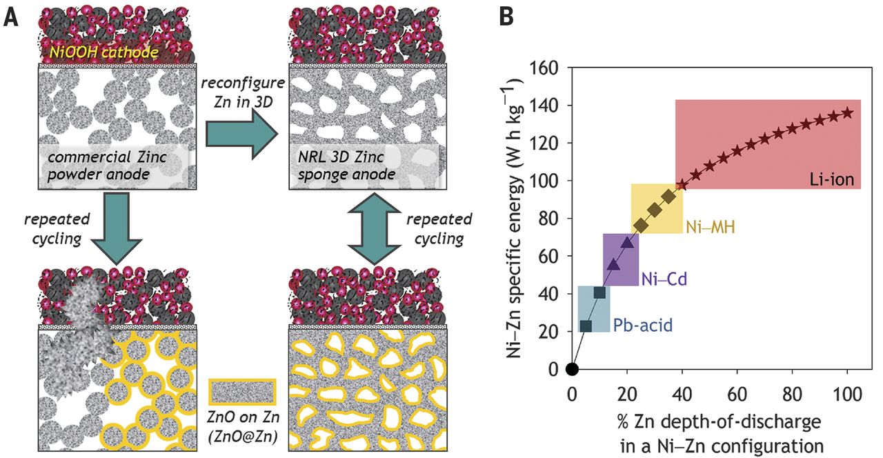
They stress benefits zinc should have over lithium types,
and the "zinc sponge" idea is probably a good one -- yet still they are
only speaking of 100 recharges. Like everything else I've read on the
subject, this was of course written before my idea last year of using
oxalate and pH 12 electrolyte. (Anywhere from pH 7.5 to pH 13 should
work.)
Has anybody in the field yet read my TE News issues from
last year and
realized lower pH electrolyte is surely the real way to tackle the
problem? In
a real chem lab they should be able to rapidly make the strides that I
haven't been able to. There may be chemists who know of a whole
selection of potential electrolytes besides oxalate they could try out.
(doubtless more complex substances, since simple ones would be listed
in the Wikipedia solubility table... and hey, before the end of the
month, I found one: CH3OH!)
Near the end of January I found that some recently were
trying nafion ion selective membrane for electrode separators, and that
this constituted "a considerable breakthough" in using zinc. Presumably
it should block soluble zinc ions, whether Zn++ (in acidic) or ZnO2--
or
Zn(OH)3- (pH 14 alkaline zincate ion).
If it worked perfectly, it would solve the problem in spite of zinc
solubility because the zinc ions would never get into the separator
sheet, so they couldn't build dendrites across it or contaminate the
plus electrode. This was outlined in this article:
[
http://advances.sciencemag.org/content/4/3/eaao1761 ]
High-capacity aqueous zinc batteries using sustainable
quinone electrodes
[exerpt]
Among the reported aqueous batteries, rechargeable zinc batteries
(ZBs)
are one of the most promising candidates because zinc anodes are
affordable and exhibit high capacity (820 mA h/g), large production,
and good compatibility with water (18‚-21). Up to now, great
progress
has been made on building high-performance ZBs using inorganic
compounds such as metal oxides (18, 19, 22‚-28) and Prussian salts
(29‚-31), in which Zn-MnO2 battery systems are most widely studied. On
the one hand, efforts on the MnO2 cathode side largely focus on
preparing high-capacity cathodes (18, 19, 22, 27, 28) and inhibiting
dissolution of Mn3+ ions (19, 24, 32, 33). Oh and Kim (32) discovered
that the addition of various manganese (II) salts can increase the
cycle stability of a MnO2 cathode. Pan et al. (19) further reported
that α-MnO2 nanofiber cathodes could display long-cycle
stability over
5000 cycles at a high rate of 5 C after inhibiting Mn3+ dissolution
with MnSO4 added to ZnSO4 electrolyte. Yadav and co-workers (27,
28)
found that a Cu2+-intercalated Bi–δ-MnO2 cathode
exhibited a
capacity of 617 mA h/g (the theoretical second electron capacity)
for over 6000 cycles against a Ni counter at 40 C and the same capacity
for over 900 cycles against a Zn anode. On the other hand, strategies
toward solving the problems of Zn anodes have also been tried (34, 35).
At high Zn utilizations, the shape change passivation and dendrite
issues also plague the life of ZBs, which seems to be a large part of
the problem of short-lived cells (28, 35‚-37). Ito et al. (38) found
that mesh-type anode current collectors with reduced areas were of
potential interest for zinc deposition. Wei et al. (39) found that Bi
and Cu substrates were suitable current collectors in zinc-anode
alkaline rechargeable batteries. In addition, Zn is known to
generate
soluble ZnO2-- in alkaline Zn-MnO2 batteries, which will poison the
cathode and cause structure distortion (28, 40, 41). Bai et al.
(41)
demonstrated that an ion-selective separator can efficiently avoid
cathode poisoning by preventing the diffusion of ZnO2--. Calcium
hydroxide
layers have also been tried to trap zincate ions and address
Zn blocking to avoid the structure distortion of MnO2 (28, 40).
<cut>
As mentioned above, a considerable breakthrough has been made on
rechargeable ZBs, especially with inorganic cathodes"
Meanwhile back at the ranch:
Oxalate electrolyte, or not?
As I thought about
it:
1. One cell in potassium oxalate, starting with fresh zinc and perhaps
with MnOOH, had discharged great at the 1.15 volt level. But when I
tried to charge it a little, it seemed as if it didn't charge. The next
discharge started about where the last one had left off. When I tried
to charge it more, the manganese didn't - according to the voltage - go
to valence 4; the voltage didn't go up to 1.5 V. And the performance
dropped off: probably I had turned the zinc into hydrate again.
2. In a cell (eg Ni-MH) with hydroxide electrolyte, the OH- ions have a
single charge. Likewise, the hydride and the nickel both move a single
charge at a time. This matches. In a Pb-Pb lead-acid battery, the SO4--
sulfate ions have a double charge. But the lead goes from PbO2 (valence
4) to PbSO4 (valence 2) in the plus side, and from Pb (valence 0) to
PbSO4 (valence 2) in the minus electrode. Again this matches, 2-2-2.
And we know that zinc works (albeit with gradual degradation at pH 14)
in hydroxide, so it must work that two OH- electrolyte ions are used at
once to change the zinc to Zn(OH)2 or ZnO + H2O.
3. In the Mn-Zn cell however, the C2O4-- electrolyte ions have a double
valence. And the calcium hydroxide Ca(OH)2 is also double valence.
Likewise, zinc going from Zn (0) to ZnC2O4 (2) is a double valence
move. But on the plus side, Mn(C2O4)2 (4) to Mn2(C2O4)3 (3) would be a
single valence move. In charging (the other direction) it's still a
single valence move. It doesn't match the valence two electrolyte ions.
That might be trickier for the molecules with a double valence
electrolyte. It could be either that the manganese won't charge, or
else, having charged, that it won't discharge and either way gives no
voltage rise. (Earlier unsuccessful attempts to charge nickel oxides
electrodes might also have had the same problem - in which case if it
can be solved, they might work as well as manganese oxides.)
4. When I made the Pb-Zn in oxalate cell last June using a commercial
PbO2 plus electrode (TE News #121), it had seemed to work, including
charging. (It probably deteriorated because I overcharged the zinc
electrodes to hydride again before knowing about that problem.) Here,
both electrodes changed 2 valence states at once, matching the double
valence oxalate electrolyte.
Conclusions:
* It is doubtless worth trying lead-zinc again. (There's 3 new cells
left of the 6 in the little battery I bought!)
* It is doubtless worth trying sodium oxalate with the bottle of it now
on order, alone or with potassium oxalate, to see if it might act as a
catalyst for the reactions that don't seem to work with potassium
oxalate. Potassium oxalate is soluble to 30+ grams in 100 grams of
water and sodium oxalate only 3.6, so if it worked only by itself it
would be pretty weak. But still much better than calcium hydroxide at
.17.
* It is probably worth trying calcium hydroxide by itself with
manganese oxides - zinc if the above doesn't work, with fresh
electrodes never exposed to oxalate. The zinc wouldn't deteriorate, but
current capacity per square centimeter of separator would be very low.
And again there's a chance it wouldn't work because of the double
valence of the electrolyte.
On a side note, when I was making manganese negative
electrodes, I figured the zinc current collectors would stay solid
because the negative voltage of manganese was higher than that of zinc.
However, I now realize that hydrogen bubbling during charging at those
electrodes caused the zinc to become brittle zinc hydride, and that's
why the terminal tabs corroded off. The zinc powder and the portion of
the current collectors within the manganese powder electrode didn't
corrode. If I had had the overvoltage raising substances (antimony
sulfide and zirconium silicate) in the zinc terminal tabs too, they
might have been okay. Or now that I have some lead sheet, I might try
making a manganese negative electrode again with a lead current
collector and see how that fares. The electrode voltage (~ -1.5 V) is
certainly excellent, whatever the other characteristics might be!
Lead-Zinc in Oxalate (with commercial lead oxide electrode plates)
Again (Jan 9th - Aborted!)
1. THE EXPERIMENT
The main difference this time from the experiments last
June would be that I was now aware that overcharging turns the zinc
into hydride, which doesn't discharge well, leading to rapidly dropping
discharge voltages. And also I was now aware that after etching the
zinc sheets in ferric chloride, I need to use solvent to get rid of
residual chloride, which would contaminate the electrolyte. Chloride
dissolves most metals including zinc and slightly, lead.
Presumably the plus electrodes were already charged up to
PbO2 at the factory, and the zinc was metallic, so both electrodes are
already charged when assembled. Thus it shouldn't have notable self
discharge, and an initial discharge should go well, as it did last June.
2. SPECULATIONS
The chief questions then are what happens during the first
discharge, during charging, and during the second and subsequent
discharges.
a) for the minus side, the Zn(0) would discharge to valence 2, either
as ZnC2O4 or as ZnO (or Zn(OH)2?)
BUT: If during discharge the zinc becomes ZnC2O4, what
happens to the K+ ions of that K2C2O4 in the electrolyte? It would seem
that the only real possibility is that they would become 2 KOH. Then
what happens to the 2 H+ left over from that?
Another possibility is that the next zinc molecule will
become ZnO from the KOH, leaving HOH... but again, 2 spare K+.
But what is happening on the plus side? Presumably as in
lead-acid, discharge would be: PbO2 (4) ==> PbC2O4 (2). But if this
happened, we would now have 2 K+ and 2 O-- left over. The 2 O-- would
react with 2 water to become 4 OH-. Hmm... that would use up the spare
2 K+ from the minus side and the 2 K+ from the plus side, as 4 KOH. How
convenient - no hydrogen bubbling off!
3. HYPOTHESES
Now with all the KOH just made, one might expect the
solution to become more and more alkaline as the cell discharges, and
as with lead-acid and sulfate, the concentration of oxalate in solution
to drop. However, what I suspect will really happen in the alkaline
case is that the KOH will preferentially react before the K2C2O4. If
that is the case, what we would see is just enough electrode-C2O4
reactions to liberate just enough KOH, and most of the subsequent
reactions will be the same as if KOH had been used as the electrolyte.
But the concentration of KOH will be very minimal and not raise the pH
(much). On discharge most of the electrode molecules will become PbO
and ZnO rather than PbC2O4 and ZnC2O4.
Some of the molecules would become oxalates, but since
metals don't dissolve in oxalate, the electrodes won't deteriorate as
they did in chloride. (Potassium Sulfate would work for lead, but zinc
would dissolve.)
Tests:
- Obviously electrical performance and capacity.
- Check pH. (suspect KOH in solution?)
- Check specific gravity charged and discharged. If it gets low with
discharge, the C2O4 is probably being used up.
- Also look for hydrogen bubbling off including during DIScharge,
especially the initial discharge.
So much for having set it all up!; I diverted back to
Manganese-Zinc.
Totally Common Ingredients!?! New Mn-Zn Cell With Very Weak
Potassium Hydroxide
One could attempt a cell with just calcium hydroxide. We
know that it is so little soluble in water that the pH only rises to 12
instead of 14, below that highest pH where zinc forms a soluble ion
that gradually degrades the electrode. It should probably work with the
zinc albeit with low current capacity.
But if used with nickel or manganese oxides discharging
and charging a single valence, might it have the same problem of being
double valence as oxalate seemed to have?
If so, there's another possibility I somehow hadn't
considered of before: use potassium hydroxide, but use such a tiny
amount that the pH stays below 13. That would pretty much have to work,
again with much reduced current capacity but giving very long cell
life. And one could select the pH and concentration, albeit from a very
small useful range.
And it was a really easy thing to try: dump out the
Ca(OH)2 from the last, seemingly unsuccessful attempt, dilute it out,
mix some very weak KOH and pour it in. I thought the last try, with
Ca(OH)2, might have been unsuccessful because there was still C2O4 in
the electrodes (in spite of washing them), but more likely it was the
two valence electrolyte thing.
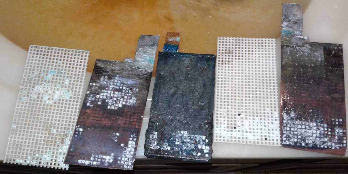 Take-apart on the 9th. Various stuff has built
up on the electrodes and the separator sheets.
Take-apart on the 9th. Various stuff has built
up on the electrodes and the separator sheets.
The blue would be copper hydroxide. The white may be a zinc derivative
- oxide or oxalate.
Late on the 9th I had the electrodes and case cleaned off.
I poured 100 cc into a beaker and did an initial pH check. 6. About
right for rainwater. Pure
water is neutral pH ~7, but when exposed to air it absorbs carbon
dioxide which makes it slightly acidic. Hmm... water without CO2 would
be better! With little
thought, how much potassium hydroxide? Hmm... I started with .25 of a
gram. After I put it in I remembered calcium hydroxide would only
dissolve .173 of a gram. So it was already in the right ballpark. I
stirred it and checked pH; about 11.5. Rather than add more I waited a
bit and measured again: 13. Treacherous stuff, KOH! Still later it
seemed to be about 12.5. Perhaps it was absorbing carbon dioxide and
losing strength? I assembled the cell and poured in 50 cc. It
started just under .60 volts and crept just over that figure in a few
minutes. I set the power supply to 1.6 volts. It started charging at
just 80 mA and was soon down to 40. Rather disappointing currents.
Well! I now was using manganese dioxide and zinc, in
potassium hydroxide. These are the most common of all battery
chemicals. The manganese side had even come out of working batteries.
The only thing I was doing differently now from commercial cells was
using the very weak solution. (...aside from using pocket cell
construction with flooded electrolyte instead of dry cells) Was the
weaker solution the only change that needed to be made to today's cells
in order to have long lasting cheap batteries?
Being almost the same as "the usual" chemistry, how could
it not work? It seemed to start taking a charge - the voltage rose. I
might have to replace the zinc electrode if it bubbled much hydrogen,
but the manganese oxide doubtless had a long way to charge. But, no
more day after day of long charging - if it didn't work in a few hours,
the zinc was probably getting hydrogenated.
It didn't work in a couple of hours. It still had the same
continuous discharge down to well under a volt, here in minutes, as
most of my cells. Changing to a new piece of zinc didn't help at all,
so the problem was evidently in the manganese 'trode. The pH had
dropped to 12. Could it be that the MnO2 electrode was still
contaminated with oxalate? But why would that mess things up anyway? Or
did that 20 amp-hours of Mn that had refused to take or hold a charge
in oxalate just need an awful lot of charging?
The best way to check it out, since I had already tried to
get the oxalate out, seemed to be to make a new electrode, the same as
the present one. For the plus side with its perforated, painted filled
copper pockets, this had become quite a task. And if I was going to the
trouble, might I try nickel oxide again instead of manganese? The
voltage would be higher. Nah! - introduce new variable after everything
was working, not before! But maybe I should make it much thinner -
having so many amp-hours of substance to charge up at such slow rates
was excruciating for testing.
And speaking of that, now with such weak electrolyte, what
would be the effect on charge rate (soon down to 20 mA) if a thinner
separator was used? I took out the plastic grill and put in a sheet of
parchment paper. It didn't seem to make any notable difference. Nor to
voltage drop in a heavy discharge. I guess thinness is only very useful
in dry cells. Wet cells with thick plastic separators are more robust,
so we'll keep the grills.
On the 10th I started charging the cell. Several times I checked to see
how much current it was drawing and how much voltage it would hold
after one, two and three minutes, then I did a load test with a 10 ohm
resistor for just ten seconds and noted the voltage after that time. It
was pretty pathetic, almost like it was a short circuit current test.
By 4 in the afternoon it didn't seem to improve much more than earlier.
In the last test past midnight it was below 10 mA, held 1.596, 1.576
and 1.564 volts, and was holding up to .8 volts in the load test
(following a couple of .78 - earlier figures being even more pathetic).
It recovered to 1.526 volts after the load test. Next the self
discharge... how much voltage would it still have by morning? I had
done my best to seal it up with maudlin clay. (AKA modeling clay, but
this certainly wasn't the best I've used.)
Sure enough, the next morning, 9 hours later, the cell was
down to .941 volts. Here was a cell now with, but for the weak KOH
solution, exactly the same chemistry as commercial dry cells, which
hold their charge for YEARS. And those were entirely different
chemicals from many other cells of mine that had similar high self
discharge. Yet it had the same awful self discharge as all my cells
have had with repeated monotony over the years. WHAT ON EARTH WAS I
DOING WRONG? (I found out later that MnO2 electrodes could be
deleteriously contaminated by zinc oxide. No doubt this one was quite
contaminated.)
Was it the Water?
What was left? Could it possibly be the water? I had been
using Britta filtered water all this time, which I understood was next
best to distilled. Activated charcoal is supposed to take out most
everything. And since I moved up here, it was starting as rain water,
which should already be pretty pure. And I had once done a test for
nitrates/nitrites (a chief self-discharge culprit) and come up with
nothing. But what was left but the water?
On the 11th without even stopping for breakfast I drove
into town and bought some distilled water. I put the electrodes and
battery parts in some of it to soak and dilute out any nitrates or
other soluble whatevers that might be in them from the Britta filtered
water. In the afternoon I put it together. It initially read about .7
volts. Within two hours of charging all the readings were above (one
was just at) what they were after charging the whole of the previous
day. And they continued to improve. But wait... this time I had put in
two zinc plates instead of one. Oops, not the best for making a good
comparison! But overnight would be the main test. Either it would still
be up near where it was not too long after taking it off charge, or it
would be way down again. But from what I was seeing in the shorter
tests, it looked like it would be the latter because after recovering
from each load test, it slowly started dropping again, millivolt by
millivolt. Still, it seemed much better than previously.
What actually happened ovenight was in between. Overnight
in 9 hours it dropped to 1.20 volts, much better than to .94 but still
completely unusable for a practical cell. I tried a load test and the
voltage dropped to .5 volts (instead of about 1 volt shortly after
charging), so it definitely had lost much or most of its energy. Could
it be that the new electrolye was good, but the electrodes were still
harboring nitrates or whatever it was that was causing the problem? I
could try all-new electrodes, or I could try diluting them again and
changing the electrolyte and seeing if there was further improvement.
The latter was the easiest. But I went out and started
milling some more wood before I got to it. Then I waited a while for
the diluting to hopefully take effect. When I put it back together
after a while a bent zinc tab shorted shorted to the copper and the
cell became almost completely discharged. By the time I had it working
properly it was already late. So instead of taking it off charge
overnight I put it on for the night. I charged and observed it some
more on the 13th. The pH had dropped under 12 according to the color of
the pH paper. 11.5?
I do think that somehow the Britta filter was putting a
bit of nitrate/nitrite into the solution. I had also put some britta
water into the lead-acid cell days previously. It too had gradual self
discharge, but it was taking many days, not hours. It seemed that
perhaps low current capacity was the chief problem.
Thicker KOH Electrolyte: Finding Solutions
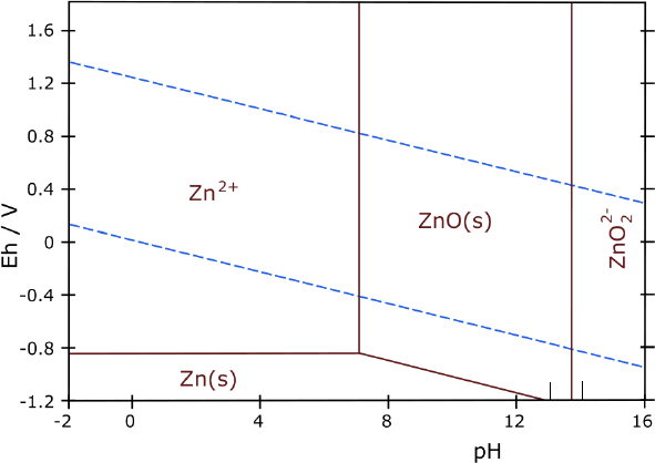 On the evening
of the 13th I decided I had had enough of ultra-weak potassium
hydroxide solution. But I still didn't have the sodium oxalate to try
out. I decided to put some more KOH into the solution. What did I care
in an experiment if it made dendrites, when I could easily remove the
plates, examine them (and maybe learn something), and wipe or clean
them off, or easily replace them?
On the evening
of the 13th I decided I had had enough of ultra-weak potassium
hydroxide solution. But I still didn't have the sodium oxalate to try
out. I decided to put some more KOH into the solution. What did I care
in an experiment if it made dendrites, when I could easily remove the
plates, examine them (and maybe learn something), and wipe or clean
them off, or easily replace them?
But rather than go whole hog, I took the top off the cell,
got some tweezers, and started dropping in flakes of KOH. It probably
wasn't even a gram and the pH still only read 13, but the decaying
voltage that had dropped to 1.4xx rose all by itself to 1.668
volts! Apparently the cell was quite well charged already after
all -- the dropping voltages weren't indicating self-discharge of the
electrodes! And in a 10 ohm discharge test it stayed over 1.2 volts
after 10 seconds. A thicker solution would surely conduct still better,
doubtless by a good margin.
Of course
electrolyte is the key. It would seem that potassium oxalate with
calcium hydroxide didn't/doesn't work right (for some reason), but that
alkali that made only pH 12 it seemed was simply too thin for proper
operation, even disregarding low current capacity. (The problem
couldn't be the pH itself, because Mn-Zn dry cells work fine at pH 7.)
pH 13 at least seemed to work, and probably wouldn't result in zinc
dendrites, although it was approaching the limit. (The limit might be
approximate, and it might vary with temperature or other conditions.
Being too near it might make zinc dendrites, just more slowly.) Perhaps
there was a possible balance there if there was no other way to make
long lasting cells with zinc.
In a 15 ohm load test for 30 seconds the cell stayed above
1.25 volts. I couldn't of course stir the solution within the cell and
the pH was down to 12 again. I added a few more flakes. Then I
graduated to a small spoon, and added a few more... and a few more....
and a few more. It was hard to keep it up to pH 13 with these small
measures as it diffused through the cell's 50 cc or so of water. pH 13
is a lot more alkaline than 12 - I understand each step is 10 times
stronger than the previous. It also took adding a lot more hydroxide to
get to. There must have been a few grams by now. (2.5 g instead of .25
g? Ya, ya, I should have measured it!) Another load test with 30 ohms
held almost 1.5 volts after 2 minutes, and then with 10 ohms held 1.25
volts after 2 minutes. And each new test was without any charging after
the previous. How much more hydroxide could I put in without getting up
to zinc dendrite territory? Enough for it to behave like a real battery?
The next morning (14th) the cell was down to 1.44 volts -
a definite improvement over any other recent result. pH seemed to be
about 13, or maybe just over. And in a two minute load test with 10
ohms it stayed above a volt and was dropping only very slowly. It
recovered - over an hour or more - to 1.415 volts, which it still held
two hours later. (Then I put it back on charge.) Without going back too
far into history, it would seem that other than seemingly contaminated
water, mainly my recent "self-discharge" problems were also related to
non-performing or very weak electrolytes. The weakness was simply
highlighted by the slight water contamination.
In the evening I checked it again and ran a load test with
10 ohms. I was just going ot run it for 2 minutes, but I left it on
until the voltage dropped under a volt: 32 minutes. At that point the
voltage was dropping only about 3 mV per minute. So it supplied over
100 mA for over 1/2 an hour, and probably would have run at least 2
hours before the voltage was under .9 volts, and even then continued
on. If it wasn't spectacular
and even at that I was obviously asking more than it could give without
substantial voltage drop, it was at least some real current for a
considerable period. Eventual recovery to 1.4 volts over the next 1/2
hour indicated substantial remaining potential.
At some point in there I read that while a cell is idle,
alkalinity 'accumulates' toward the negative electrode, while acidity
forms near the positive. Hmm! That doesn't sound like a desired effect
when it's the zinc where the alkalinity needs ot be lowest.
Sodium Oxalate
Obviously the cell powered a load better, and the seeming
"self discharge" decreased, as electrolyte density increased. But one
could put a lot more oxalate in the solution than hydroxide without
making it pH 14 and forming zinc dendrites. I wanted that sodium
oxalate to arrive and fervently hoped it would work with all the
chemical components of the cell, both for charging and discharging
reactions. Another possibility occurred to me: potassium oxalate and
weak potassium hydroxide, under pH 13. For that, all I had to do was
add the oxalate and see what happened.
But I didn't try the potassium oxalate and the next day
(15th) the sodium oxalate did arrive - along with my new microscope,
which I had finally broken down and bought one of. That evening I added
just
.55 g of it to the cell. And no potassium oxalate. The cell voltage
soon rose from 1.377 volts (or so) to 1.392. Not the giant increase
back above 1.5 volts hoped for. At least it suggested it had some
effect, and it was just 1/2 a gram.
With about 50 cc in the cell and
solubility of just 3.6 g/100 cc, I could only put in less than 2 g max.
Since it's not very soluble and it had to work its way around the cell,
I waited a while. It didn't rise any farther.
After some hours playing with it, charging currents seemed
to be about double, but it didn't seem to drive a load any better. Then
I must have left it on too long: charging current went up from 70 mA to
100, and when I took the charge off, the voltage dropped fairly
rapidly. I suppose I must have turned the zinc into hydride.
Speaking of that, I had immersed some previous zinc sheets
in distilled water. Over a period of days, bubbles formed. Apparently
the hydrogen was coming out of them. I and the piece I had read also
said the hydride would come out rapidly above 90°c. It didn't say
it had to be in water for that, but no doubt it does. I put the zinc
plates in water in a bread pan on the woodstove.
Alcohol: Methyl Hydroxide
I got rather tired of everything (perhaps especially the
continuing disappointments) and left the battery for a day. The oxalate
just didn't seem to be working the way I had expected. There were a few
more things I could try.
Hydroxide always worked and was the obvious choice, but pH
14 was a problem for zinc. All the alkaline first and second row
elements that would dissolve made pH 14. No others were soluble enough,
including "ammonium hydroxide" (ammonia) which has strange properties
and little
actual hydroxide. I thought back to when I had first started trying to
make a better battery chemistry, long ago and had been thinking of
organic things. Methyl things... acetone (methyl-methyl ketone)...
methylene chloride (no chlorides!)... Why had my thoughts strayed in
those directions?
I went to the Westlab.com site and searched on "methyl".
Methyl test kits... methylene chloride... methylene blue... methyl
red... orange... violet... methyl alcohol. That was the only vaguely
promising looking substance. What was it? CH3OH - a
hydroxide! In fact, an alternate name for it is Methyl Hydroxide. How
blind I've been! Why had my thoughts strayed into other directions? If
I had heard that name years ago, I'd probably have been right onto it!
(Well, maybe, anyway.) What was its pH in solution? A search was
frustrating.
It seemed it was hard to determine; that most pH measuring techniques
don't work with organic solvents. But it sounded like it might be
slightly acidic if anything - nothing like pH 14. Some seemed to think
it wasn't even proper to speak of an organic compound as having a pH.
WOW! A simple,
soluble hydroxide that wasn't pH 14! How had I missed it all these
years? I guess what I had missed was that:
wood alcohol = methanol = methyl alcohol = methyl hydrate = methyl
hydroxide.
Might I say that I found these multiple confusing? None
of them sound the same substance as each other, but they are all names
for
CH3OH. I don't recall ever hearing the
last of those terms "hydroxide" until looking it up now, which should
have been the
one to "ping" in my mind while doing battery research and lead me to
experiment with it. In fact it was years before the fact that:
"hydrate" = hydroxide
really sunk into my brain.
OTOH, there's no point kicking myself. Either it doesn't
work for some obscure reason anyway, or
nobody else has figured it out in over a century of battery research so
a decade isn't bad.
Again the pH could probably be tweaked to 12 with calcium
hydroxide, or to any desired alkaline value with very weak potassium
hydroxide. I ordered some CH3OH. And of course a couple more things
to get to the "free shipping" amount, 75$. (The beaker arrived broken.)
Taxes, dangerous goods
surcharge... there went yet another 100 bucks. (So soon after my last
order! But ideas don't all come at the same time, or necessarily at
convenient times.) Maybe I shouldn't
have ordered 150$ worth of DC powered LED lights (for off-grid
experiments and for sale) the day before.
Something twigged in my memory. Yup! I have a 3/4 full one liter bottle
of
"methyl hydrate". It's been sitting around for ages and I've had no
idea what to use it for - or what it really was. It says "Central
Builders Supply - $1.29"... so no doubt purchased by my parents in
Courtenay in the 1970s. (How did I get it?) Groan! Now I remember
picking it up and looking at it early in my battery experiments. And
I'm sure I looked up the formula. What made me set it aside and forget
it without trying it? I guess the idea that some sort of hydroxide was
the best electrolyte hadn't yet dawned on me.
And evidently I didn't need to order the "methyl alcohol".
It's exactly the same thing! I could probably have just got more at a
hardware store for $1.29... or more like $12.90 or more today. Oh well,
if it
works I'll have lots for a small production lot.
I mixed this solution:
360 g distilled water
40 g methyl hydroxide (the hydroxide electrolyte)
1 g potassium hydroxide (to raise the pH above neutral)
I cleaned and rinsed all the components and again washed
the electrodes in gasoline.
The zinc electrodes had areas of a black color with
sparkles, especially on the back side. Under the new microscope, the
surface looked broken up, and the sparkles were mostly triangular tiny
shaped bright crystals. Zinc oxalate? If it was going to break up
anyway, did I need to etch them? And then... might I anyway do better
to torch them to roughen the surface?
I assembled and filled the cell. Initially it only read
around .3 volts. I connected the charge at 1.7 volts, and it was
quickly down below 100 mA, and to 50 after 15 minutes or so. All pretty
disappointing. But when I disconnected the power after only a few
minutes of charging, the voltage seemed to stay much higher than usual
for such a short charge. But it didn't seem to hold up any better than
usual after a few hours charging and a longer sitting time.
On the 19th I took it apart and put the Mn electrode into
paint thinner. Was something within the electrode causing self
discharge that might be dissolved in that? I put it back together and
filled it with the same mix. It started out at .60 volts but was rising
by itself ("self recharge"?) and soon it was .75. It being very late at
this point, I left it overnight without charging it.
Proton Membranes
There is yet another possibility to consider: one can use
two different electrolytes with a proton exchange membrane in between
them. For example, nickel oxyhydroxide works fine in pH 14 potassium
hydroxide. And nickel [plated] current collectors won't oxidize away.
But zinc has that soluble ion. Perhaps methyl hydroxide, or potassium
oxalate, would be the choice for the negative. They could each have a
separate electrolyte with a Nafion film in between. (Oops, I think
Nafion is attacked by strong alkali. Maybe something else on the "+"
side, then.) Just hypothetical at this point, but two electrolytes
could provide a solution if one side doesn't like an electrolyte that
works well in the other one.
And what is the magic of nafion? It only passes protons,
not negative ions. Among its properties, it would seem the ends of the
polymer chains are "sulfonate groups". The stuff costs a fortune for
small pieces. What else has sulfonates? "Lemon Fresh Sunlight"
dishsoap. Going back to what I was doing long ago, rather than putting
it directly in the electrode, could dense, heavy watercolor paper
impregnated with Sunlight act as a proton ion membrane between the
electrodes?
I realized this might even solve the potential problem of
charging manganese to permanganate. A tiny bit will dissolve (turning
the water purple), and when it drifted to the negative electrode, it
would solidify into manganese hydroxide, contaminating the negative and
gradually disintegrating the positive. With a proton membrane separator
the MnO4- ions couldn't get to the negative side. A tiny bit would stay
dissolved and the rest would remain. Only the "+" side water would be
purple. That was what I wanted for the longest time and a potential
solution was right in front of me.
 If it could be
charged to permanganate, with permanganate being only slightly soluble
and assuming the reaction was reversible, the "+" side voltage could be
.80 volts instead of .25 volts, making the cell theoretically 2.0 volts
instead of 1.45 -- 38% more energy could be stored in the same cheap
Mn-Zn cell, which was already higher energy than lithiums. That would
of course be assuming nothing like zinc dendrites formed in the plus
electrode. Owing to the slight solubility, it seems like a good chance
any that started to form would dissolve.
If it could be
charged to permanganate, with permanganate being only slightly soluble
and assuming the reaction was reversible, the "+" side voltage could be
.80 volts instead of .25 volts, making the cell theoretically 2.0 volts
instead of 1.45 -- 38% more energy could be stored in the same cheap
Mn-Zn cell, which was already higher energy than lithiums. That would
of course be assuming nothing like zinc dendrites formed in the plus
electrode. Owing to the slight solubility, it seems like a good chance
any that started to form would dissolve.
It is probably also why the Ni-Mn cells I made so long ago
charged to such high voltages, since the positive was actually
nickel-manganese, which would have formed nickel manganates of
similarly high oxidation states:
+.8 v - -1.5 v = 2.3 v. (They actually charged to as high as 2.6, just
as the Mn-Zn charges to over 1.5.)
In those I had put the Sunlight straight into the
electrode, but its sulfonates probably had about the same effect.
I hope the same thing can be accomplished with the
dishsoap, but in the interests of better research I broke down and
ordered a square foot of nafion membrane. (Egads, I just have
to stop spending so much money!)
An interesting and perhaps relevant feature of nafion, considered a
flaw in the abstract of a book I saw for sale on eBay, Nafion
Nanocomposite Membranes for the direct methanol fuel cell, is that
alcohol can "permeate it from the anode to the cathode during
operation". This may mean that the methyl hydroxide and its hydroxide
ions can actually go through it even when water and permanganate ions
can't.
An interesting and perhaps relevant feature of manganese
is that above pH 13 it can form a soluble ion [Mn(OH)3-] if it is
overdischarged. So keeping the pH below that may keep the MnO2 plus
electrode as well as the zinc minus from deteriorating.
Now, how does one seal around the edges of the nafion?
Hmm... Apparently with barium metasilicate. I can't even seem to make
practical batteries at all, and this is getting complicated! Still, if
one wants really better batteries...
Back to the Cell
I had to wonder, at some point, why the already small
number of short circuit amps had become hundreds of milliamps instead.
That indicated a tenfold drop in performance. As I had changed zinc
electrodes a couple of times, and electrolyte more than once and now to
a more concentrated solution, the only remaining active component was
the MnO2 electrode. There had been whitish build-up on the zinc
electrodes which I eventually attributed to calcium. The perforations
in the positrode looked whitish. I went after them with paint thinner
and a cotton swab... and then a toothbrush. That seemed to get rid of
the whitish color around the holes.
The cell drifted from .995 upward to 1.10 volts by itself
over 25 minutes. At that point I put the charge on. Currents didn't
seem to be any higher.
Before bed I put a 30 ohm load on it, and left it for 22
hours. What harm could it do? In theory, nothing should dissolve or
degrade. It spent about 21 hours delivering less than 1/2 a volt, but
it kept on going and going. The next evening (22nd) I turned it off
putting out .345 volts. It recovered within a minute to .75 volts and
continued eventually to rise to .92. Then I put it on charge.But after
a couple of hours, the current went up and when disconnected, the
voltage dropped rapidly.
It seemed to me that, with this having happened several
times in total, it could hardly be anything but the zinc forming
dendrites and shorting across the gap. This in spite of the charts
showing zinc as having no dissolved phase between pH 7 and 13.5. Was
the methyl hydroxide so acidic that in spite of the small addition of
potassium hydroxide, it was below pH 7? As others have noted, it
definitely was hard to measure the pH in the organic solution. When I
had put the pH paper in it turned green for a moment, indicating slight
alkalinity, then orange indicating mild acidity, with a stripe of green
at the edge of the wetted area.
Was my whole idea of using zinc, for various reasons
depending on the electrolyte, an unworkable one then?
But another possibility altogether for using zinc had
started tugging at my mind. Zinc, whether as Zn(OH)3-, ZnO2-- or Zn++
ions, couldn't pass through or even enter a nafion membrane. If there
were no zinc ions in the separator sheet, would it not be the
case that they couldn't short circuit through it? Zinc dendrites might
build up, but they should all stop at the nafion separator sheet, there
being no more zinc ions to be had in that direction. But had no one
else already tried this? Having thought of it, and with so many people
having tried to use zinc as an electrode, it seemed like a fairly
obvious idea. Sure enough, a web search found some papers. (Excerpt
above) The first
one said it represented "a considerable breakthrough" in the use of
zinc in batteries. A couple of other however mentioned putting zinc
oxide powder together with nafion power and then dissolving out the
zinc oxide, to get bigger pores. The purpose of that wasn't made clear,
but it
would seem to be counterproductive for using a zinc electrode in a cell.
I started getting frustrated and discouraged. But perhaps
I was too hasty... Difficult tho it might be to measure, the solution
surely
must have some pH value. After a bit the pH test strip had said
it was a bit acidic. I think "somewhat acidic" was said of methyl
hydroxide, and there was only a bit of potassium hydroxide in it to
raise the pH. With nothing else in the solution, the bit of KOH would
raise the pH to 12 or 13. But if it had to counter an acidic substance,
it would doubtless take substantially more to get the pH up. A pH below
7 would explain zinc dissolution and
dendrites. The next thing to try before abandoning the present setup
(after inspecting the zincs and seeing if I can see the dendrites, then
cleaning or replacing them) is to add some more KOH to the mainly CH3OH
solution to get to - or at least make sure it's in - a somewhat
alkaline condition and not forming Zn++ ions.
And I was reading of "poisoning" MnO2 electrodes with zinc
ions. Perhaps it's time for a new "+" side as well, after all the
experiments this one has been through. It's doubtless highly
contaminated by now.
Pourbaix diagram for copper. (in chloride, oh well.)
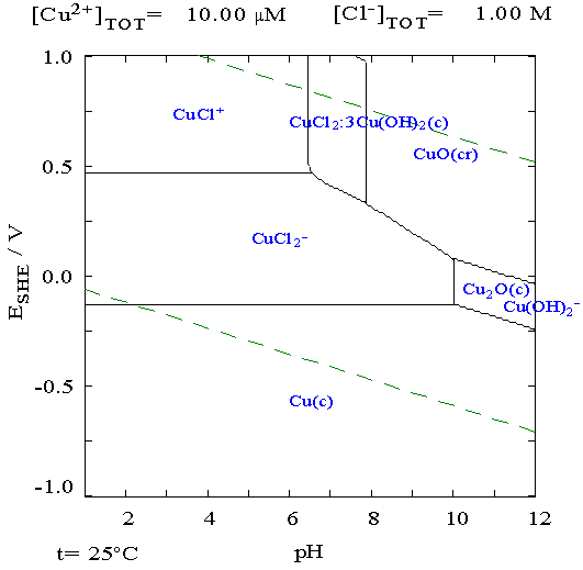 Examining the "discharged" zinc plates and the separators with the
microscope was
revealing: there were dendrites all right. But the orange color was
unmistakable. They were copper dendrites, especially in a couple of
small patches. Perhaps there were holes in the paint there, but it
surely pointed to a low alkalinity or acidic solution that would
dissolve copper. There was some darker color in them in some areas that
probably indicated zinc mixed with the copper. Then there were some
blue blobs in one area that were probably copper hydroxide - by
deduction, blue for copper and hydroxide being the only thing in the
electrolyte for it to combine with. Beside one was a telltale copper
dendrite.
Examining the "discharged" zinc plates and the separators with the
microscope was
revealing: there were dendrites all right. But the orange color was
unmistakable. They were copper dendrites, especially in a couple of
small patches. Perhaps there were holes in the paint there, but it
surely pointed to a low alkalinity or acidic solution that would
dissolve copper. There was some darker color in them in some areas that
probably indicated zinc mixed with the copper. Then there were some
blue blobs in one area that were probably copper hydroxide - by
deduction, blue for copper and hydroxide being the only thing in the
electrolyte for it to combine with. Beside one was a telltale copper
dendrite.
Copper Dendrite on the electrode separator
grille - magnified x40(?)
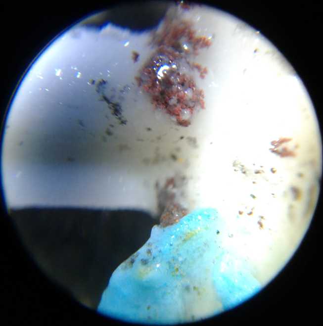 Copper (& some zinc) dendrites and some
blue copper hydroxide
Copper (& some zinc) dendrites and some
blue copper hydroxide
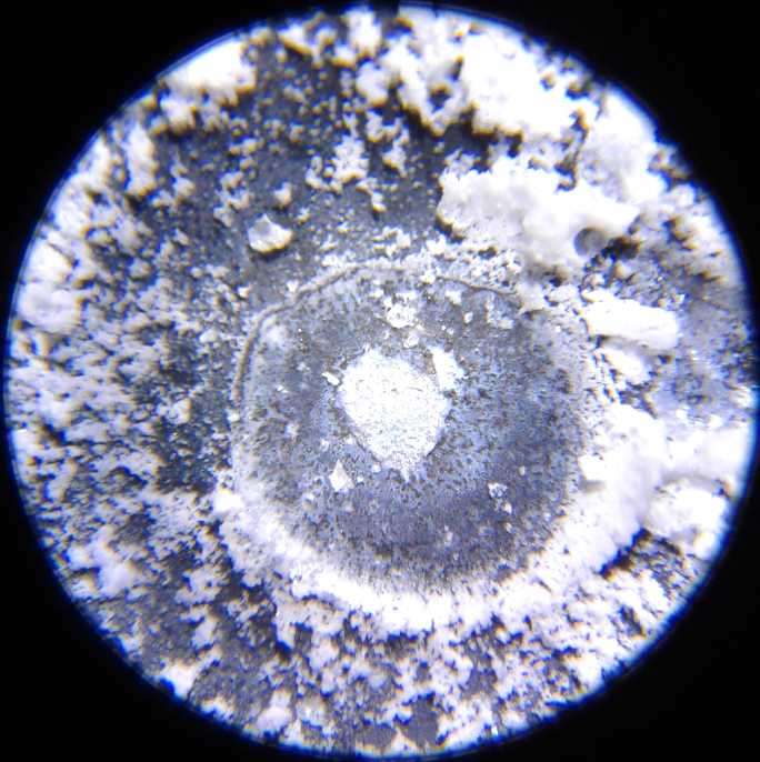 Coarse zinc oxide (I presume) on the zinc
plate, and some very fine within a slightly raised
Coarse zinc oxide (I presume) on the zinc
plate, and some very fine within a slightly raised
"dome" area.
The "fine' particles are what I would suppose will recharge to metallic
Zn form readily.
I suspect the "coarse" form comes from the particles temporarily
dissolving instead of
staying closely on the surface. So at the right pH I suspect "fine"
will be the main or
only form. ...This could of course all be a mistaken assumption. Next
try, with higher pH,
should tell.
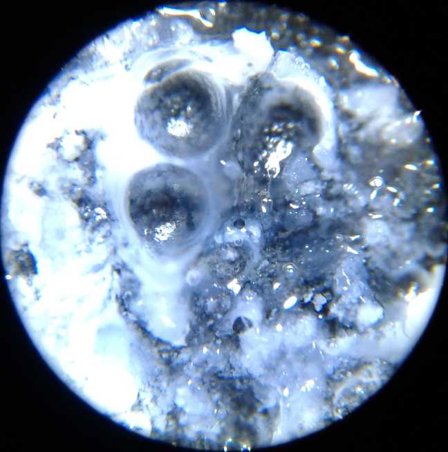 More
perplexing were some white blobs. A couple were in
the separator grille, more were on the surface of the zinc electrodes.
Left over calcium saying that my previous cleanings hadn't been very
good? or maybe zinc hydride? More "salty" looking white crystals
(above) probably indicated zinc oxide. But the way they stuck up, I
could
hardly see how they would plate back on nicely during recharging.
Between
the grains looked mainly like zinc, and in a few raised areas were very
fine white patterns right on the surface of the zinc. (surely zinc
oxide.) These I could
imagine recharging properly.
More
perplexing were some white blobs. A couple were in
the separator grille, more were on the surface of the zinc electrodes.
Left over calcium saying that my previous cleanings hadn't been very
good? or maybe zinc hydride? More "salty" looking white crystals
(above) probably indicated zinc oxide. But the way they stuck up, I
could
hardly see how they would plate back on nicely during recharging.
Between
the grains looked mainly like zinc, and in a few raised areas were very
fine white patterns right on the surface of the zinc. (surely zinc
oxide.) These I could
imagine recharging properly.
Well, I'm glad I bought the microscope. I'm not sure how
much of this I would have caught with just handheld magnifying lenses.
Yep! Makes me wonder what I've missed before. [Would a SEM or an X-ray
diffraction spectroscope help even more?... I would probably have
little to no idea what I was looking at; how to interpret the images!]
On the 29th I added 3 grams of KOH to the remaining ~300
cc of solution. So per 100 cc (roughly):
90 cc HOH
10 cc CH3OH
1.25 g KOH (5 times as much)
The pH test strips I usually use have one serious
weakness: The pH 5 color looks about the same as the 12. And that's
what it showed. So I tried the two other types I have. One merely
indicated it
was alkaline rather than acid, so I took the first reading as being 12.
Specifically for alkalinity pH test strips with three different "spots"
on them seemed to indicate it was about pH 13. 13 was a bit higher than
I had intended to go, but within limits. Now there was not only CH3OH,
but a higher concentration of KOH, one that by itself would have raised
the pH to 14, or at least very close to it.
I cleaned the Mn'trode and the Zn'trode with the powder
inside the two plates in varsol, rinsed off the plastic pieces and
case, and put it together. This time at least I understood that it
wouldn't be good for much because the Mn was doubtless contaminated
with zinc oxide, changing the crytal structure.
The voltage was very low, only a little over 100 mV. I put
it on 1.7 V charge. It drew 200 mA but soon dropped under 100 and down
to 40 within an hour. Testing over the day showed the performance was
dismal and it didn't hold charge well at all. Evidently even if the
electrolyte was good, new electrodes (or at least a new Mn'trode) were
needed.
http://www.TurquoiseEnergy.com
Haida Gwaii, BC Canada