Turquoise Energy Ltd. News #129
covering
February 2019 (Posted March 3rd 2019)
Lawnhill BC Canada
by Craig Carmichael
www.TurquoiseEnergy.com
= www.ElectricCaik.com
= www.ElectricHubcap.com
= www.ElectricWeel.com
Special Report: The Second Industrial Revolution:
Exciting New Machines for Local and Home Manufacturing
(Report follows "In Passing")
Month In Brief
(Project Summaries etc.)
- Better LED Lighting - Expanding My Solar Systems - Solar
Electric Hot Water Experiments - HAT 36-40 Volt Plugs and Sockets - New
3D Printer - Amazing New
Production Machines - My CNC Router... and Plasma Cutter - Tidal &
Wind power notes -
Ground Effect Vehicle
In
Passing
(Miscellaneous topics, editorial comments & opinionated rants)
- Oceans Tell of Global Warming
- Jet Streams & Global Circulation Patterns - Recycling Plastic
LOCALLY - ESD
(Eccentric Silliness Dept.)
- Project Reports
-
Electric
Transport - Electric Hubcap Motor Systems
* Ground Effect Vehicle (not a lot to say)
Other "Green"
Electric Equipment Projects
* "Off Grid" (etc): 36-40 Volt "HAT" Plugs & Sockets - New 3D
Printers
* New 3D Printer: Anycubic I3 Mega
* Better LED Lighting & Plant/Grow Lighting
* CNC Router & Plasma Cutter
Electricity Generation
* Further Expanding my Solar System - How many watts are those panels,
again? Never full nameplate
power: 75% seems to be a practical figure - Panel Efficacy: Crap in
winter as expected - Still More Solar Panels - and Monitoring Output.
* Solar Hot Water Panels: simpler to make than ever
Electricity Storage -
Turquoise Battery
Project (Mn-Zn, Ni-Zn or Pb-Zn in Oxalate Methyl
Hydroxide electrolyte)
* Thinking of Options with Nafion Membranes (no actual project work)
February brought winter with it. Whereas we had so far had
only some frosts, Saturday morning the 2nd it was -7°C. It went up
to -2 then dropped back to -7 overnight. Sunday it hit -3.5 and that
night went up to -2.5. It was too cold to work outside and almost too
cold inside. Better to sit in
front of the woodstove and feed it as much wood as I dared. Around the
18th it went up to +2
to +4 during the day for a few days, but that didn't seem to thaw out
all the frozen ground and the ice in my rainwater barrel. Then it went
down to freezing again for the rest of the month. There was a little
snow on parts of this island, nothing that stayed long in my area.
But by the end of the month that seemed mild compared to
farther south where the whole west coast got heavy snow, from Vancouver
Island through Oregon and a bit even as far south as Los Angeles.
 The fine line dividing warm and cold on many
days this February:
The fine line dividing warm and cold on many
days this February:
Wherever the sun hit, the frost melted and the hoses ran.
Wherever it stayed in shadow all day, it all stayed frozen.
The month thus seemed to start out pretty slow, but
somehow by the end I seemed to have done quite a few pretty cool things
and found a lot to write about - even too much. Maybe it was partly
because it was too cold to mill lumber.
I wanted to get this newsletter out on the 1st of March.
I'd have had a couple more days if some deranged person or
persons long, long hadn't decided that February should be the only
month to have only 28 days. Why wouldn't January, February, March and
April all have 30 days? It's the same number of days either way - 120.
(Surely it must have been decided by a committee!)
Better LED Lighting
 Now the fluorescent holes need insulation,
gyproc and all the things that go into making gyproc smooth.
Now the fluorescent holes need insulation,
gyproc and all the things that go into making gyproc smooth.
(I'll probably put in a second LED panel too.)
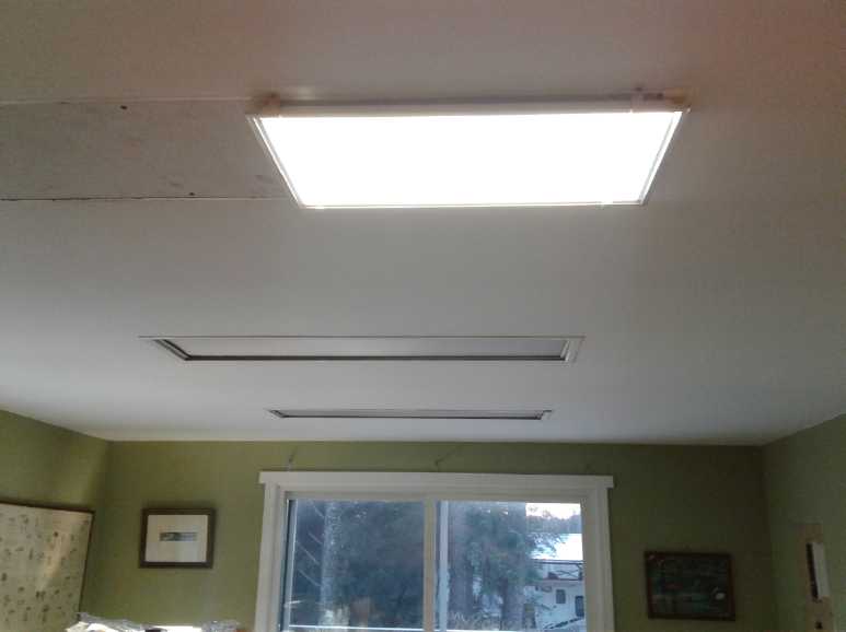
 I
pulled out a ceiling-flush fluorescent fixture and
put up an LED panel light in its place in the dining area on the 3rd.
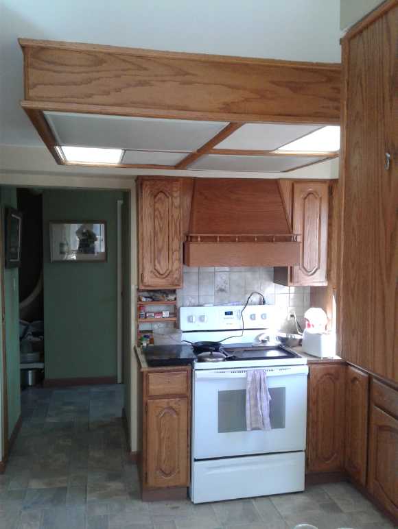
Then I did two more
in the big wooden light fixture in the kitchen ceiling on the 8th when
I
realized how easy it would be if I just left the fixture and the
fluorescent lights within it in place. With
two 24 watt LED ceiling panels, even with the morning sun coming
through the window switching them on markedly brightened the room and
vanquished the shadows. There'll never be another dull day in the
kitchen!
I
pulled out a ceiling-flush fluorescent fixture and
put up an LED panel light in its place in the dining area on the 3rd.
Then I did two more
in the big wooden light fixture in the kitchen ceiling on the 8th when
I
realized how easy it would be if I just left the fixture and the
fluorescent lights within it in place. With
two 24 watt LED ceiling panels, even with the morning sun coming
through the window switching them on markedly brightened the room and
vanquished the shadows. There'll never be another dull day in the
kitchen!
They were so nice I ordered another set of 3, and I just
might even go for a third trio. As a bonus the power supply is external
and they can easily be run off the 36-40 volt DC solar power instead if
required.
Expanding My Solar Systems
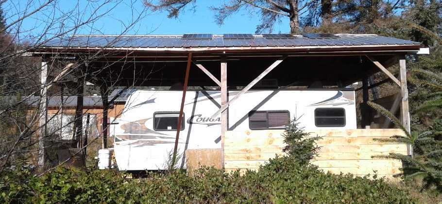
Toward mid month
temperatures hovered around freezing. Having sold no solar panels, on a
sunny day I put up three on the roof over the travel trailer, which I
had discovered got more winter sun than anywhere else. The results
being good, on the 20th I added a fourth one to more fully utilize the
1 KW plug-in grid tie inverter. At this point I'd used 6 of the new
panels and even if I sold all the rest I wouldn't be making any money
from the palette of panels. But I still want (probably come summer) to
put a
panel on the converted Chevy Sprint EV and two on the Miles electric
truck. That would make 9 of the new 305 watt panels (instead of my
intended 5), plus the four ~250 watts I'd brought from Victoria, plus a
bunch of 100 watt and a couple each of 90 and 208 watts - for sale but
no takers. Then on the
19th someone bought 8 of the 305 watt and on the 27th another 6 went,
so I could finally start repaying the bank line of credit... or use
some of the cash for other things. I had already ordered a plasma
cutter and a new 3D printer. I had finished off the several thousand
dollars I had put into my Paypal account a year ago and dug into my
bank account when I ordered the plasma cutter. It had felt like "free
money" for the last year whenever I could pay for something with
PayPal. I put some more money back in my PayPal account. (probably
safer than in a bank anyway.)
Near the end of the month there was quite a bit of sun and
now 10 panels well engaged, and the solar started putting out good
energy, doubtless lowering my power
bill a bit. That's great, but mainly I really want to be ready for
future potential extended power outages. All we need here to have that
is for some disaster like a tsunami to disrupt Masset and close the
fuel oil barge receiving facilities there for an extended period. Or in
common with everywhere, to have some other national or international
fuel supply disruption - a financial system disruption could bring
things to a halt since everything runs on credit. The south grid will
have hydro power whenever it rains enough. Any "on grid" time then will
be that little bit longer the more the solar panels that are
contributing to conserve the lake water. My panels will be diverted to
personal use if or when the grid power is off. In fact, if there were
enough solar panels or wind power, the south grid is well positioned,
because the hydro can supply as needed and the alternate sources can
help keep usage of the lake water low.
The north grid is almost
wholly diesel, with 3 or 4 good solar installations on public
buildings. They'll be out of luck unless some serious alternatives
are put into place. The pace for that so far is underwhelming, and if I
myself do a tidal project at all, at least at this point, it'll be more
of a demo than an immediate significant contributor.
Solar Electric Hot Water Experiments
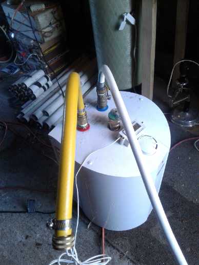 Some time back I bought a
small hot water tank for under the kitchen sink. It takes far too long
to get hot water there and in common with the rest the iron rich water
stains everything brown including my dishes. A hot water tank right
under the sink filled
with rain water sounds marvelous. But I still haven't installed it.
Someone on youtube compared solar electric panels to heat water in a
tank versus an actual solar hot water pumped system. He had two or
three PV panels to get enough voltage to heat the tank.
Some time back I bought a
small hot water tank for under the kitchen sink. It takes far too long
to get hot water there and in common with the rest the iron rich water
stains everything brown including my dishes. A hot water tank right
under the sink filled
with rain water sounds marvelous. But I still haven't installed it.
Someone on youtube compared solar electric panels to heat water in a
tank versus an actual solar hot water pumped system. He had two or
three PV panels to get enough voltage to heat the tank.
I decided to try my little tank with just the 36-40 volt
solar system and hooked the tank up in the garage to the hose and the
DC solar power system. It worked, more or less, eventually. I got very
carried away with taking readings over time for several days and the
report is
down near the bottom under Electricity Generation.
I also looked at a new idea in solar panels: a simple coil
of pex pipe. It looked so easy to make I bought a 100 foot coil of pex
pipe and made part of a collector box. (no report or picture on that so
far.)
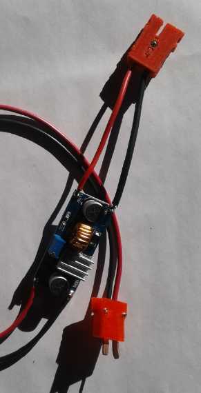
HAT 36-40 Volt Plugs and Sockets
HAT 36 VDC plug & CAT 12 VDC click-
lock socket on 36 to 12 volt converter
 I (finally)
brought my 3D printer in from the shipping container and started in
designing plugs and sockets for 36 volt wiring and appliances. I didn't
get too far and went on to other things.
I (finally)
brought my 3D printer in from the shipping container and started in
designing plugs and sockets for 36 volt wiring and appliances. I didn't
get too far and went on to other things.
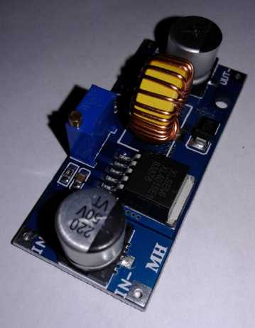
Near the end of the month some simple 36 volt to 12 volt
DC to DC converters arrived. (actually "from" and "to" whatever you
want, as set by a trimmer potentiometer, as long as the output is lower
than the input. 5 amps max.) It made sense that they should plug into a
36 volt HAT plug on the input, and have a 12 volt CAT socket to plug
something into on the output. But I had to solder alligator clips on
the input. I don't much like that because they are prone to miswiring
and to coming off.
So I went back to designing the HAT plugs and sockets. I
got one pair done and used them for it, but I wasn't satisfied. They're
not quite ready for prime time. Maybe next month.
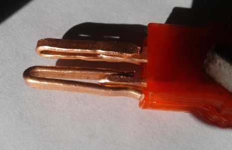
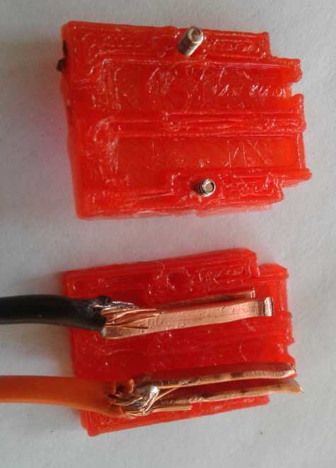
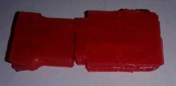 HAT Plug & socket with blades and
(?)receptacles inside, mated together.
HAT Plug & socket with blades and
(?)receptacles inside, mated together.
When I soldered wires on the shells were pretty
cramped inside and wouldn't close very well.
And they might look better if done on a better 3D Printer.
New 3D Printer
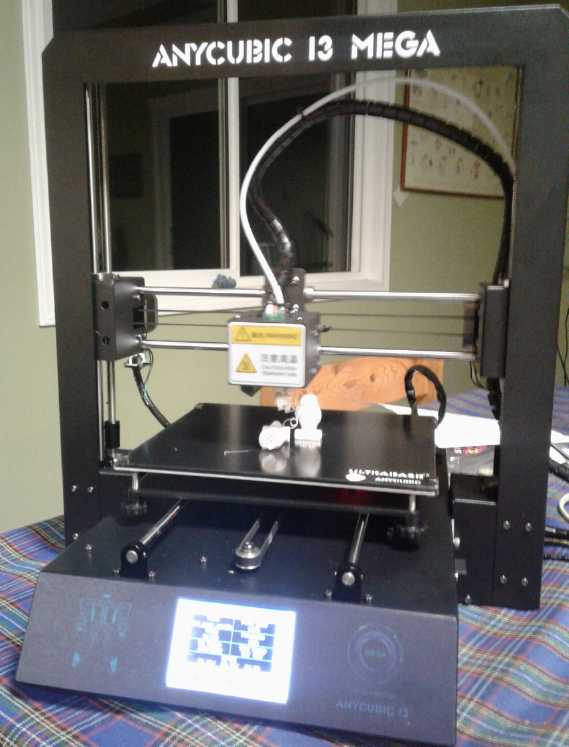 I had some
trouble with the 3D printer, and it occurred to me that new ones were
probably pretty cheap and better. I ordered an AnySolid I3 Mega
for around just 350$C. It arrived on the 26th and I set it up on the
27th. It came with tools and a spare extruder (my problem part in the
old printer) and a couple of other spare parts.
I had some
trouble with the 3D printer, and it occurred to me that new ones were
probably pretty cheap and better. I ordered an AnySolid I3 Mega
for around just 350$C. It arrived on the 26th and I set it up on the
27th. It came with tools and a spare extruder (my problem part in the
old printer) and a couple of other spare parts.
I did the supplied test print "two owls". (One didn't
stick to the bed and fell over during printing - ouch! The other came
out well.) The beads are considerably finer than on the RepRap Pro
Mendel, but the catch is it prints much slower. Now I suppose will
come the learning curve with the new software.
In addition to better looking parts, I hope to be able to
print some "porous" electrode
parts for batteries that I couldn't do with the old one.
Amazing New Production Machines
I spent some time writing up the Special Report
(below the In Passing section) on a number of exciting new
machines I saw in videos for home production of various things. There
were so many for so many purposes that I started thinking that the
whole face of the production of goods might be about to undergo a major
change to more local levels.
My CNC Router... and Plasma Cutter
One of the videos showed a home CNC plasma cutter. This
could make
nice cuts through steel sheets and plates. It's what I was trying to be
able to do with the "pulsejet steel plate cutter" that I never finished
making in around 2010. I discovered home plasma cutters are now common
and I ordered a 120 volt unit from PrincessAuto.com . Perhaps a bit of
a lightweight, but easier to plug in than a 240 volt unit I have no
outlet for. It came
on the 28th.
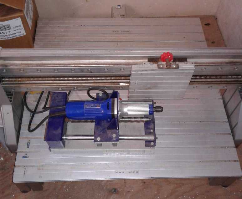 Then I looked
at the 30x30" CNC table I had and the controller that came with it. It
was old stuff (1991), but the table seems good. I thought the
controller would only be trouble with an old "parallel printer port" to
connect to the computer (predating USB by over 10 years), but then I
looked on eBay and found that new ones have all the very same plugs!
Then I looked
at the 30x30" CNC table I had and the controller that came with it. It
was old stuff (1991), but the table seems good. I thought the
controller would only be trouble with an old "parallel printer port" to
connect to the computer (predating USB by over 10 years), but then I
looked on eBay and found that new ones have all the very same plugs!
Underneath, eBay "suggested" several "USB to parallel
printer port adapters". I had some time back been told that "those
never work right", but if that's the way everybody is doing them, I
assume they must.
I used to have one - for a printer I used to have - but
couldn't find it. So I ordered one off
AliExpress.com, for under 2$. Now I just need to find the DB9 connector
pinouts and make cables to connect the controller to the stepper
motors. There seemed
to be a vexing lack of information on line for this simple thing,
considering they seem to be the same connectors as on new units.
It would be very nice to have a working CNC router again,
and with
a water bed and steel slats placed on the table, it should work for a
plasma cutter as well. I'm hoping to use my "general purpose" CNC table
to gain the functions of a couple of the other machines I saw in videos
as well. Especially I hope it can do printed circuit board making with
a miniature router and drill, which is very fine work to accomplish.
Tidal Power, Wind Power: A couple of Design Observations
I previously mentioned the idea of launching a tidal
power unit from the beach at low tide and maintaining it on or
retrieving it from the beach as well, with an automatic rudder to steer
it out into the channel at high tide and into the best current for
maximum power
generation.
But with the craft tethered from the bow and with it
pulling toward the shoreline, it occurs to me that the rudder action
will be different. The rudder will need to be at or near the bow - near
the tether, and it will be steered the opposite direction to how a
free-sailing boat would point. To stay away from shore while tethered
there, it has to
counteract the shoreward pull of the rope at the bow. This is similar
to towing a log with a small boat: one steers the outboard the opposite
direction because the drag of the log is the overriding factor. (Gosh
it's been a LONG time since I've done that! 1976.)
Or maybe the mooring line shouldn't be at the bow? Maybe
it would be better if it was amidships somewhere? Along with the
rudder. Or maybe it needs two rudders to keep it out in the flow and
also best lined up into it.
I watched a video on youtube about a vertical axis wind
turbine model with 3 "hybrid blades" that was for sale commercially for
mounting on houses. The blades seemed to be propeller shapes at the
front, but with the tail end chopped off. I surmise the "open" tail
ends ensured it would start spinning by providing something for the
wind to push on when it wasn't.
Otherwise it looked like many other VAWTs until I saw the
dimensions: 3 meters tall and 3 in diameter. My little experiment was
only about 1/2 a square meter. This one was 9. Greater efficiency is
good. Catching 18 times the cross section of wind is much better! I
started to think in those terms if I was going to try again - make it
more of an engineering project, and find the windiest spot for it. And
another way to get the generator spinning faster, to get more voltage
without winding a new stator, would be to gear it up. A flat belt and
pulleys, or maybe a couple of those plastic gears I made in 2016?
Ground Effect Vehicle
One would think that with it being too cold to work
outside except in brief bursts I'd have been working on this. In fact,
I only very lethargically picked away at a drawing. One notable change
was that if there was going to be a "tail" in the middle for lateral stability, then I would attach the
rudder to that instead of having another tail at the back. Owing to
that position, I also made it quite large. It's an unusual arrangement,
but
I think it should work.
In Passing
(Miscellaneous topics, editorial comments & opinionated rants)
Oceans Tell of
Global Warming
 Record cold winters have many people reasonably questioning that
there's
global warming, with much speculation about a coming "mini ice age".
But at the same time there's been record heat in parts of Autralia. I
suspect the next northern summer may change many minds, but in
the meantime, someone mentioned that the oceans are a more reliable
measurement of trends because they hold so much more heat than the air
does.
Record cold winters have many people reasonably questioning that
there's
global warming, with much speculation about a coming "mini ice age".
But at the same time there's been record heat in parts of Autralia. I
suspect the next northern summer may change many minds, but in
the meantime, someone mentioned that the oceans are a more reliable
measurement of trends because they hold so much more heat than the air
does.
They seem to show a slow but definite trend over the last
three decades. Unless that unexpectedly reverses, expect significant
sea level rise. Polar ice is melting at an increasing rate, and as
water warms it expands. As ice melts on Greenland and Antarctica they
become lighter and will probably rise up, displacing still more water.
Then as water encroaches over the land in other places, that land may
become heavier and will tend to sink, compounding the effect.
Current advise has it not to buy a home at an elevation of
under 50 feet, but this generalization will obviously vary by region.
My own house is just 25 feet above the high tide mark, but it's not
wide open to the Pacific. It seems quite unlikely there'll be any big
storm surges or tsunamis in Hecate Strait. (...And if you're in
Greenland, you're probably pretty safe.)
Jet Streams & Global
Circulation Patterns
My earlier analysis
of what was happening with the circulation patterns of Earth's air was
incomplete. In TE News #109 I noted that the aerosol spraying at high
altitudes makes high altitude clouds that blanket the atmosphere up to
those altitudes, perhaps 25000 to 40000 feet. To oversimplify, the
whole vertical layer
of blanketed atmosphere is all ground-level warm. It doesn't have the
vertical temperature gradient that drives the Earth's predominant
circulation patterns.
One thing I missed was that the temperature gradient still
exists. But now it starts above those clouds. We now have a relatively
less
active layer of air going up 5 to 7 miles before we hit the more usual
vertical circulation driving patterns. Of course the air is far thinner
up there, so the forces driving the circulations are weaker. The jet
streams are now at a much higher altitude than historically.
The other thing I didn't note is that with the sprayings
being quite inconsistent, some places on some days may have normal
circulation
gradients from surface levels, while other places and other days there
will be only the high altitude drivers. This is probably why the jet
streams often become broken up and chaotic.
But if the circulatory forces are weaker, they are also
farther up from the ground and so less coupled to it. Recently a
commercial airliner set a new time and speed record going from (IIRC)
Los Angeles to London. It broke the sound barrier at (?)800 MPH with a
(?)300 MPH jet stream tail wind.
Recycling
Plastics LOCALLY
Along with being
able to manufacture with plastics, the potential grows for local
plastic recycling. More and more, the imagination is the limit to what
can be done to solve our many longstanding problems of waste and
pollution and create a better future.
First my grievances with
the egregious annual garbage collection fee led me to think that since
this is
a remote island, we should recycle our own plastics. I remembered the
video of a guy who cut his scrap plastic into little pieces, then
heated them in a waffle iron until they melted into multi-colored slabs
of solid plastic. In Victoria I was paying (probably overpaying) up to
40 $/sq.ft. for 1" thick UHMW to use for motor molds. Could I have made
my
molds - and made them much thicker - with plastic scraps and a
large "waffle iron"?
To recycle plastics locally one would need pretty minimally:
(a) to get people to bring CLEAN plastic and sort it into the right
bins: LDPE (plastic bags), HDPE, PP, PETE... maybe PS, and "other".
Those named
would account for most of the material.
(b) a washer to clean them better anyway - depending on type, use and
shape of items.
(c)
a
chipper/shredder to break the plastic into bits. (It might be
washed after chipping it up instead of before. Solves trying to clean
inside of bottles
with thin necks or other awkward shapes.) The shredder might be the
trickiest piece of equipment to buy or make, but it could surely be
done. Where quantities warrant, there could be different chippers for
different types of plastic. Otherwise, different types would be done in
batches.
(d) a giant "waffle iron" or two. This would be two plates of heated
metal that would come together, with a rim all around, to melt the
plastic into sheets or bars. 2"x2" angle iron, or square tube, might
make good sides. The metal enclosure would keep air out as much as
possible. The video presenter's waffle iron seemed to work pretty well,
but I remember much of my polypropylene rope material vaporizing(?)
when I melted it in open air. Again plastic extruders are also a
possibility. (One to extrude filament for 3D printing would be nice!)
I'm pretty sure that could all be bought or made for quite
minimal
cost for small scale use. In the cities bigger units and more of them
would be required. In the long run it would surely be much cheaper
everywhere than finding more landfills or sending plastics to China for
recycling.
The thickness of finished pieces would depend on the
amount of material placed on the bottom (rimmed) plate. It could be
1/16" or less to 1" or more to make different sorts of products. There
could be a long
heater maybe 6" wide to make plastic "boards", and a short but wide one
to make fat slabs for various purposes and multi-colored butcher
blocks. Or perhaps any length "boards" - or thinner sheets - could be
extruded out one end of a press? (Doubtless trickier, but might be
practical - if not here, then in cities where there is more material to
process.)
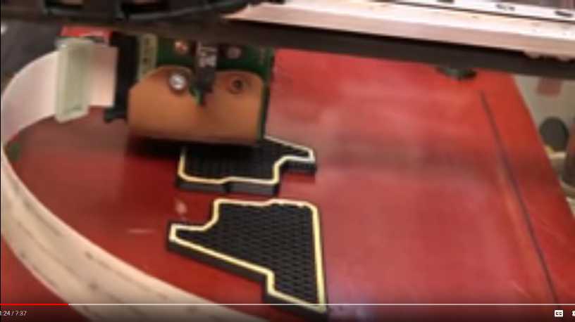
(e) On the 14th (Happy Valentine's Day!) I found a video
showing a desktop vacuum forming machine, Vaquform. (5 Incredible
Machines For Manufacturing at Home #2) Again we find new ideas and
products that can change the whole way we do things and what we are
able to
dolocally, even at a very small scale. If one made thin recycled
plastic sheets, they
should be amenable to vacuum forming. The colored sheets from scrap
could then turned into things - like back into food containers. This
would result in the same plastic being recycled and used over - and
over - again
locally.
Why should these practices not now be adopted locally
everywhere? All the rope and fishnets (good PP!) and other plastic crap
littering the beach (not to mention drifting across
the oceans) might start to be seen as valuable raw material instead of
as a gargantuan clean-up problem.
I wonder if anyone in authority here would go for that and
if it would be
economic enough to pay someone to do it? No doubt here it would only be
a part-time or one person operation. Or could colorful plastic products
even be
exported from Haida Gwaii? Could they be a "Haida Gwaii signature"
product?
One must inject a bit of caution of course. Plastics do
degrade in
the sun, and perhaps gradually with reprocessing. Garbage in, garbage
out. At some point the plastic must find a "permanent use" out of
sunlight or be completely reprocessed. Obviously polyethylene sheets
used for greenhouse coverings for a year or two, which then rip to
shreds easily, won't be readily turned into a strong, durable product.
But I expect most plastics used for most things can be reused many
times.
ESD
(Eccentric Silliness Department)
I accidently typed "bug" instead of "big", and later noticed it. The
spelling checker didn't catch it. There must be a bug in the spelling
chequer.
2B ... or something else ... that is the question, when selecting a
pencil.
Some have said "Doing the same thing over and over and expecting
different results is the definition of insanity." But in music and
theater it's known as "rehearsal" or "practice".
It used to be that you had to unlock something and get in before you
could swipe anything. Now you have to swipe something in order to
unlock and get in.
Does your area suffer from "crunchy ground syndrome"? The cause is
generally outdoor temperatures below 0°C. Help Global Warming
is hoping to secure sufficient funding to fix the problem by leveling
all the mountains and highlands into the oceans, thereby also adding to
global real estate with sales to help offset costs. When the land is
all flat, boring lowlands, the ocean breezes will blow freely over the
continents and return them to the salubrious oceanic climate Earth
enjoyed in the Carboniferous period before the Permian highland and
mountain building era made the climate arid, cold and continental, and
killed off most species of life. Please donate generously to HelpGlobalWarming.con
and together we can cure crunchy ground syndrome.
"Witch Hazel" was recommended for a skin condition. There seemed to be
several choices. I just bought the most basic one because I didn't know
which witch hazel was which. (Q: Which hazelnuts come from witch hazel?
A: Witch hazelnuts.)
Irregular English Verb Irregularities
Past tense of throw: threw - "The team threw the ball game"
Past tense of blow: blew
Past tense of snow: snew - "In
the blizzard the wind blew strongly and it snew heavily."
Past tense of show: shoe - "I
shoe him where his grammar was bad."
Past tense of grow: grew
Past tense of glow: glue - "The room grew brighter as the lamp
glue more strongly."
"Dr. Suessingston, I presume?" In the fall, leaves leave
the trees and fall,
leaving fallen leaves in the eaves. Some rake leaves in fall, but when
the raker leaves, more leaves fall. So I prefer to leave them. At the
electric car dealership, some leaves fall onto Leafs. Relief comes in
the spring when
the fallen fall leaves have left and the trees
spring to life
and releaf.
Why would anyone think spraying lice-all would kill germs? Lice don't
eat germs.
Special Report
The Second Industrial Revolution:
Exciting New Machines for Home and Local Production and Recycling
As I watched some youtube videos about new
production machines, it dawned on me that a new industrial revolution
is unfolding before us. The first one,
while greatly advancing technology, increasing productive capacity and
improving quality of life,
brought us centralized "mega factory" production facilities and locked
the average person out of the mainstream of being able to turn ideas
into new commercial products.
Then very recently we had the computer revolution and then
the internet revolution, bringing
powerful computing power and the world's information to our fingertips.
This has accelerated the spread of new ideas and by the way enabled the
"second industrial revolution" - a revolution in producing things.
I remember the first time I heard of some sort of printer
that could create a solid object out of thin air (around 1987 as best I
recall - before the internet). I heard it from a person who was always
well ahead of everyone in the new technology knowledge curve. Of course
as a newly invented device for industrial prototyping it would
obviously be far too costly for an individual and I never expected to
have any such thing in my lifetime.
The next time I heard about it was on the internet or in
the news over 20 years later, when someone in London had created a 3D
printer the average person could afford, the "RepRap" ("replication
rapid"). The technology itself had enabled the replication of the
special plastic parts it itself needed without costly injection molds.
The 3D printer could print 3D printers! Some enterprise and the
internet made it available worldwide, to anyone who wanted one. I spent
850$ and two weeks to put mine together. Just this month I bought a new
one from China for 350$ assembled, which does much finer detail (and
prints correspondingly slower).
But 3D printers, it turns out, are just one of many new
production machines now making their appearance.
The second industrial revolution builds on the previous
revolutions to bring multiple custom
machine production and fabrication capabilities to our fingertips.
Videos reveal a wide array of exciting new developments in tools
and equipment for making things, within the budget reach of individuals
and very small groups. It becomes apparent that computer controlled,
fast, precision manufacturing can and likely will become more and more
local, less and
less concentrated in giant factories situated wherever labor is
cheapest.
That's not to say that everyone will want to have all the
tools and
to learn how to do everything to produce whatever they want, but that
at some point there'll come to be various people in town who will make
a business of providing many things locally that presently are perhaps
made in China or wherever and transported around the world. Presently
these technologies are either quite new, or newly available at
personally affordable prices. So far there's no culture of local
production. There's no
local "AliExpress.com" umbrellas for home manufacturers to help clear
away the daunting overhead tasks of doing small individual
transactions:
marketing, sales and deliveries, and for complying with onerous
government regulations.
One thing I seem to be spending considerable time at is
watching videos,
and now sometimes spending further time commenting below them hoping to
broaden peoples' perspectives. This is what brought me to this topic.
Youtube is always suggesting
videos, which suggestions are sometimes actually valuable, and you
discover things you would never have guessed existed without them. On
about the 14th I found 5 Incredible Machines For Manufacturing at
Home #2.
In the middle of that, an ad cut in for a "CNC plasma cutting machine",
yet another incredible machine which I actually found more interesting
than the video and looked it up. I did a separate article about it,
below.
Then I finished watching the original video, and I also found Incredible
Machines videos #1 and #3 - a total of 15 devices. I
particularly noted the following devices.
Kniterate
An automatic knitter that will make your own custom
designed, custom size, custom colors clothes. From wool, acrylic or
cotton yarns. There were clothes designs for it on line. When I was
little my Mom used to knit us warm woolen winter wears by hand.
Scarves, sweaters, tuques... She spent hours at it. (Even fur lined
moccasins one year!) I don't suppose many moms would know how these
days. Now it can be automated! (Except for the moccasins.)
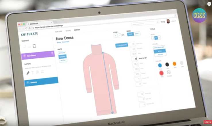
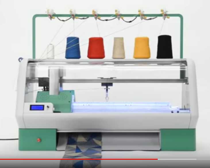 Kniterate. Do we now have the potential to
easily design and make whatever clothes we want?
Kniterate. Do we now have the potential to
easily design and make whatever clothes we want?
Hi neighbor, can you do me a new tee shirt please? How
about that pattern but in tan and brown? Cotton acrylic blend. Make it
with a little extra room at the shoulders. Sleeves ending a little
above the elbows. Noo, a vee neck please, and a breast pocket. That's
it, thanks! Can I pick it up tomorrow? Great!
What will happen to the big department stores? What will
happen to the Asian clothing sweat-shops?
Wazer
 In video #1
there was a CNC abrasive waterjet cutter. That was quite exciting, but
it was more limited than industrial waterjets. While it would do thick
plastic and 1/2" aluminum, it said it wouldn't do 5/16" or even 1/4"
steel, which would be my minimum for cutting motor rotor type parts. So
the plasma cutter is still a go. The other thing that ruled it out was
the price: 7500 $. Presumably US$, so 10000 $C. But we can be sure they
will only get cheaper and better.
In video #1
there was a CNC abrasive waterjet cutter. That was quite exciting, but
it was more limited than industrial waterjets. While it would do thick
plastic and 1/2" aluminum, it said it wouldn't do 5/16" or even 1/4"
steel, which would be my minimum for cutting motor rotor type parts. So
the plasma cutter is still a go. The other thing that ruled it out was
the price: 7500 $. Presumably US$, so 10000 $C. But we can be sure they
will only get cheaper and better.
In 2008 I had never heard of abrasive waterjet. By 2010(?)
I knew of it but couldn't find a place that would do it. By 2012 I had
found a place where I could get it done, and not long after, more than
one place.
Now there's the "home unit". If I'm making things long
enough, some day I may want one of my own.
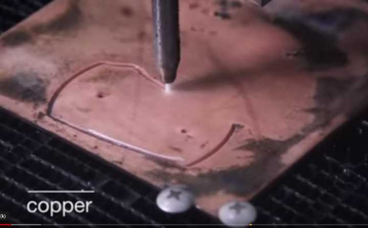
Other Mill
 A PCB
router/driller for doing single and double sided circuit boards
by routing away the unwanted copper areas, leaving the desired traces
and drilling the holes. It would work from the same PCB CAD generated
files that PCB making houses use. Ooh, that would sure be nice to have!
I wonder how much it is?
A PCB
router/driller for doing single and double sided circuit boards
by routing away the unwanted copper areas, leaving the desired traces
and drilling the holes. It would work from the same PCB CAD generated
files that PCB making houses use. Ooh, that would sure be nice to have!
I wonder how much it is?
...Or, can I do the same thing on my general purpose CNC
table with a "dremmel" router and bits?

Vaquform
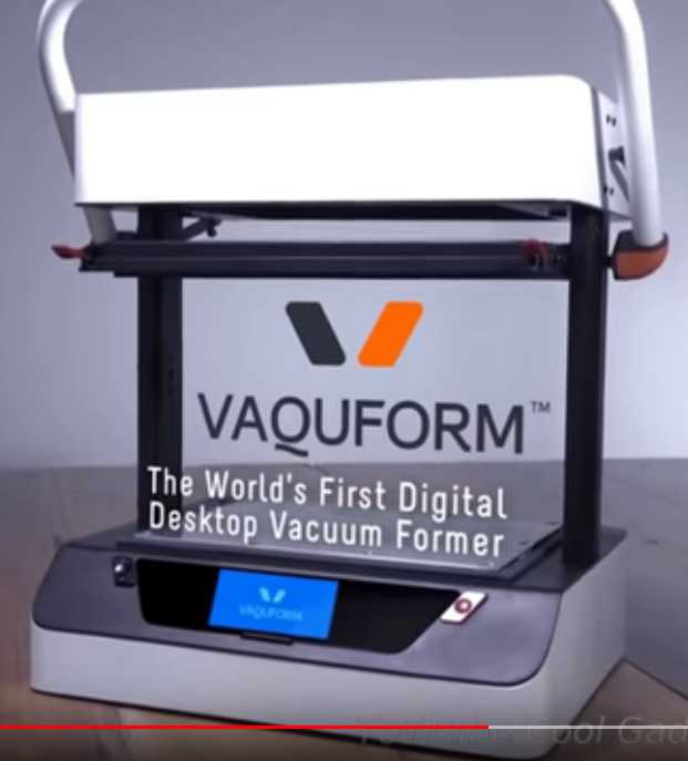 A small plastic vacuum forming table/machine. With this one could
make many typical food packages and things. That would make a good way
to
turn locally recycled plastics back into useful products! (I also saw a
video suggestion for doing a home made one, but didn't get to it.)
A small plastic vacuum forming table/machine. With this one could
make many typical food packages and things. That would make a good way
to
turn locally recycled plastics back into useful products! (I also saw a
video suggestion for doing a home made one, but didn't get to it.)
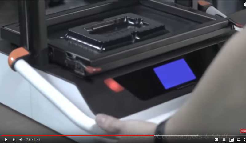 Vacuum forming a plastic packaging part from a
sheet of flat plastic.
Vacuum forming a plastic packaging part from a
sheet of flat plastic.
A great way to re-use locally recycled plastic?
DobotM1 and MakeArm
These were desktop robotic arms that could take multiple
attachments for 3D printing, PCB
routing, drilling and pick-and-place parts placement on printed circuit
boards, among other functions. To move a tool in a straight line,
obviously there must be a lot of trigonometry, but of course it's all
automatic. My mind isn't getting around what they're really capable of
and I didn't check out prices. Their reach would be limited compared to
a CNC table machine. No doubt we shall see what uses people put them to!

 Dobot M1 and Make Arm
(Oops, I got Make Arm's top arm straight on - not the best illustration)
Mazlow
A CNC router that can work on 4' x 8' sheets of plywood stood on edge.
Steel cables and pulleys move the router around instead of the
usual long screws. It doesn't take up 1/2 the shop space of a
horizontal
unit. And it was supposed to be substantially cheaper as well.
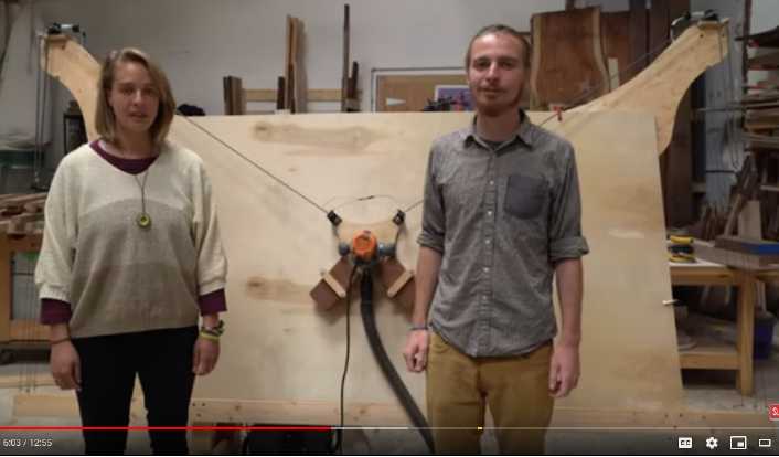 The creators of Mazlow with their space and
cost saving wood routing machine
The creators of Mazlow with their space and
cost saving wood routing machine
Stoneflower
A 3D printer (or was it a clay extrusion head for 3D printing?) for
extruding clay or other materials of similar texture. Wow! I could see
attaching such a head to a general purpose CNC table and making pottery.
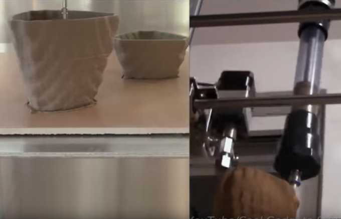 Stoneflower 3D printing clay pots for ceramic
or porcelain.
Stoneflower 3D printing clay pots for ceramic
or porcelain.
Can it do cups, plates, bowls, serving dishes?
...Porcelain mouthpieces for my Supercorders?
3D Printer for Making Sintered Metal Parts
 Another notable product was a 3D printer to make small metal parts.
(Somehow I have forgotten the name. But it was called "Atomic Diffusion
Additive Manufacturing".) It
works like a regular plastic extruding printer, but the plastic strand
has metal powder embedded in it - probably to the maximum point at
which
it'll still extrude well. Any metal or alloy may be printed.
Another notable product was a 3D printer to make small metal parts.
(Somehow I have forgotten the name. But it was called "Atomic Diffusion
Additive Manufacturing".) It
works like a regular plastic extruding printer, but the plastic strand
has metal powder embedded in it - probably to the maximum point at
which
it'll still extrude well. Any metal or alloy may be printed.
This was an "industrial machine". (Industrial today - Home
making tomorrow! ...But you do need to melt the metal, etc.)
One first prints the part as normal, but 20%
oversize. Then much of the plastic is dissolved in a solvent, leaving
just enough to hold the particles together. Then the part is heated in
an oven. The plastic melts away and the metal particles fuse
together, and it shrinks by 20%. It is said to give accurate, complex,
strong parts made to order, in a day or so.
Sintered metal isn't wholly solid. It has minute air
spaces, but it's (apparently - in this case) about as solid as cast
metal, which also has air spaces.
I must say this seemed really exciting! If I thought I
could make metal parts with this, I might be sorry I ordered the plasma
cutting torch.
I do have a question (which could probably be easily
answered on line). Why can't one just buy and use the metalized
filament in an any old 3D printer?
The same company also had a separate composite plastic
printing process with chopped carbon fiber plus a continuous filament
carbon fiber, that make a non-metallic part much stronger than a simple
plastic printed one. Having tried "conductive plastic" with chopped
carbon fiber in it and had it clog up my print extruder, I think I'll
have to pass on that myself. But why would one not print polypropylene,
by itself or with something else. It must have good strength?
FarmBot
When you know exactly where
you planted each plant, you know exactly where to
water.
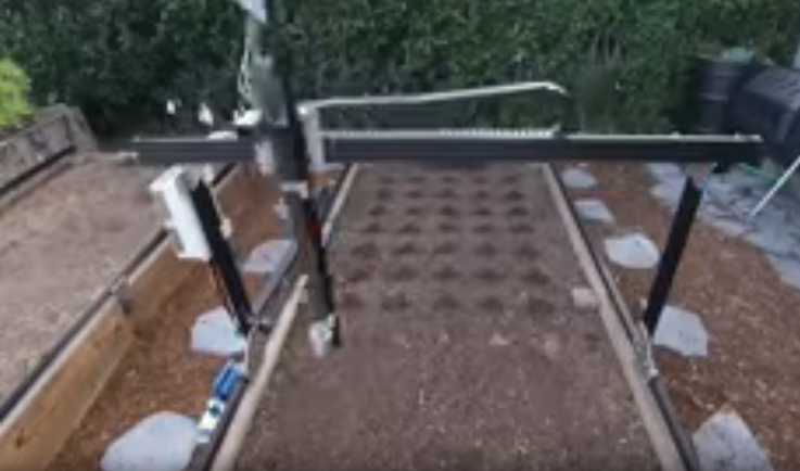 A CNC gardening machine. I
should have known somebody else would
think of this, when I still haven't got around to making one in several
years. It
comes in two sizes - roughly 1-1/2 meters by 3 and double, 3 x 6 m.
A CNC gardening machine. I
should have known somebody else would
think of this, when I still haven't got around to making one in several
years. It
comes in two sizes - roughly 1-1/2 meters by 3 and double, 3 x 6 m.
It's somewhat
different from my concept. Instead of riding on rails on each side of
the garden, it works on a garden plot framed with wood boards. It is
much lighter and wouldn't do the
grunt work of tilling the soil and prepping the plot for you. Mine was
intended
to [hopefully] be able to convert a lawn or other ground into a
prepared garden
plot, picking up the grass/weed clods and dumping them in a pile or in
a wheelbarrow. And other heavier jobs - perhaps spreading compost and
mulch and so on. (But one reason I haven't made mine is because it
would be a pretty ambitious project.)
It did however plant seeds, water and stomp out weeds, and
it had some good
software and some good tool attachments for those purposes, which were
said to be
3D printable. (I haven't followed them up yet.)
It would seem there's still room for my idea, which would
make it
into a pretty complete gardening solution. It could be scaled up even
for
farming on a very substantial scale, replacing tractors and combines
and harvesting the crop along with the other functions.
With the special-job tools
already designed by Farm Bot one could possibly take it farther,
faster. I doubt I'll
ever find the time, but this is surely the future of crop production.
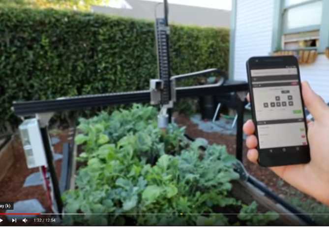 Doing something remotely with cell phone app
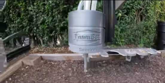 The seeding tool at work.
How far are we from dialing in the date and the vegetables
(with the growing locale pinpointed by Goggle or something and a tie-in
to the weather predictions), and just watching everything grow, coming
back at dinnetime on the day it says something
is ready?
With all these new, decentralized production tools, are
there still going to be big factories for making automobiles, trains,
washing machines, solar panels, and so on? There may be. A solar panel
factory in China says they have 10 production lines going full time.
(or was it 30? Memory, ugh!) But already many automotive factories are
closing. It is getting easier and easier to produce whatever is wanted
on a smaller and smaller scale. Is there a real economy of scale having
10 (30?) production lines in one place, or might they better be
separate plants closer to where the solar panels are to be used? Maybe
the
silicon wafer production should be centralized but not the heavy
tempered glass
panel production and final assembly? I don't pretend to know just how
all this will develop or should develop, but it seems obvious that
change is in the wind.
And then, how much value is there in having sprawling
cities? For at least a century, the greater the concentration of
population, the more and more varied the services that could be offered
to
the citizens. But now even in a remote location I can order whatever
specialty things I want on line more easily than I could obtain them in
medium-sized Victoria city 40 years ago. Living in a city is less
valuable than it used to be. And cities grown too large are
prone to contagion. It has been suggested that for reasons of both
local food supply and sanitation, cities should be kept to under about
1/2 a million people. (Obviously that can only happen after the
population has been reduced - which it will be partly by diseases
sweeping through huge cities. Then it needs to be kept managed.)
Again I won't pretend to know how things will work out,
but the potential for change and decentralization without accepting a
drop in living standards is greater than it has ever been before since
we've had
modern living standards.
"in depth reports" for
each project are below. I hope they may be useful to anyone who wants
to get into a similar project, to glean ideas for how something
might be done, as well as things that might have been tried or thought
of... and even of how not to do something - why it didn't
work or proved impractical. Sometimes they set out inventive thoughts
almost as they occur - and are the actual organization and elaboration
in writing of those thoughts. They are thus partly a diary and are not
extensively proof-read for literary perfection and consistency before
publication. I hope they add to the body of wisdom for other
researchers and developers to help them find more productive paths and
avoid potential pitfalls and dead ends.
Electric Transport
Ground Effect
Vehicle
This project keeps
is another that keeps getting pushed to the side. I did however at
least do part of a drawing of how I hope to make the radio controlled
model, using the new wing profile intended to provide the craft better
longitudinal stability. (And there's always the "Stealth" aircraft
approach of last resort: high speed computer controls sensing and
minutely controlling the rudder and elevator to damp out tendencies to
instability.)
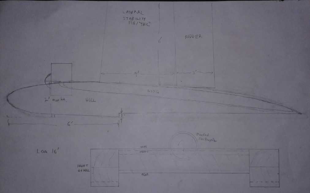 "Catamaran" layout ground effect vehicle with
ducted
"Catamaran" layout ground effect vehicle with
ducted
fan propeller, 16 feet long (model to be 1/4 scale, so 4 feet).
Width is to be 10' or less to be trailerable without disassembly.
Details like the take-off "step" hulls and combining the lateral
stability fin with the "tail" and rudder are being thought out
for trials on the model before trying a person-carrying 'vehicle'.
Other
"Green"
Electric
Equipment
Projects
"Off Grid"
(etc):
38 (33-45) Volt DC "HAT" Plugs & Sockets
On the 10th I finally decided to tackle this project. With a hammer I
flattened a #9 AWG solid wire to what seemed like a good shape for
blades. I ended up with 1.5 mm x 4.0 mm. It was a substantial cross
section and different enough that it couldn't be plugged in crosswise
to what was intended, so plugs couldn't be inserted backward.
To be more sure of getting good
connections, I decided the blade length would be 10 mm instead of 8.
Then I went into OpenSCAD and made HATPlug.s and HATSocket.s
from CATPlug.s and CATSocket.s and started modifying
dimensions. I put the pins a little closer together and didn't leave
room for a screw in between them as I had with the 12 volt CAT design.
This would mean one couldn't accidently plug into the wrong voltage
outlet. As the pins were also 4 mm wide instead of 5.5, the whole
plastic plug shell ended up smaller in all dimensions. This was
agreeable - even if it was just plugs, there's no use having needless
extra bulk. The socket was a little longer since it needed room for 10
mm pins inserted instead of 6, but was likewise thinner and narrower.
Since I still intended to screw these shell halves
together (with this design of shell), I extended the little
grips on the outside edges to be big enough to hold tiny screws and put
holes through them, so there would be one screw on each side, which
would actually be better than just one screw in the middle even if
slightly more work to assemble.
Of course, it's possible to make shells differently. Just
look at all the different plug shells and sockets for 120 volt plugs,
and they (mostly) all work together. Another design I may try sometime
is to have the 'front' attach to the 'back' rather than the top half to
the bottom half. And they can be made to glue together instead of bolt.
Or molded of cast rubber or plastic...
Every time you change a number in OpenSCAD, you can hit F5
to have it redraw the plug 'instantly' with the change. So you see the
progress as you go and it gets mesmerizing. I worked on it much too
late into the night.
The next day I finished the plug design and got out the
ReprapPro 3D printer. I hadn't used it since I moved in 2017. The bed
was way out of adjustment. Adjust as I might, I couldn't get the PLA
plastic print to stay on the bed and make anything. And in trying to
clean the nozzle, I seemed to mess up the extruder temperature reading
and things went haywire. I finally had to quit.
Next day I went back and tried
again. If the bed was hotter, wouldn't the plastic stick better? I
turned it up from the 55°c default for PLA to 65°. I poked
around the extruder wires with needlenose pliers, pushing and pulling
the thermistor and the heat resistor, and it started working. Then it
seemed to read the temperature, but wrong, and I could smell the heat.
I poked some more and suddenly it read 350°c instead of 205°.
It gradually cooled off, and for the moment seemed to be working. I had
set it up in a room with no window that opened for fresh air and I was
sorry for that after the extra high temperature, which probably
vaporized some plastic.
I designed a small test cube and printed it. It worked! So
I tried the plug again. That worked too. Then I shut it off. The
plastic was stuck solid to the glass even after it was cool. I had to
pry the pieces off with a knife. Other than laying the plastic on a
rather thick it seemed pretty good. (It was the default setting, but it
needs adjustment for slightly different plastic spool wire diameters.)
I saw a couple of minor mistakes, but mostly it just needed the plastic
to print more thinly so things would fit as designed.
Next I went out to the garage to make and bend the copper
pins. I flattened some more of the same wire. But the fatter - and work
hardened - copper wasn't amenable to being bent how I wanted. One piece
broke at the bend. It obviously wasn't going to be practical with the
thicker pins. No doubt it could be done, but each pin would be a
struggle. There had to be another way to make pins that wouldn't slide
in and out of the housing.
At first I thought to try further flattening the inside
ends, spreading them out more and then bending them around to form a
crimp connector. That would make the inside too fat to slide through
the slots, and at the same time would allow crimped-on solderless
connection. Then I realized they wouldn't bend around to crimp unless
they were annealed with a torch. That too seemed like much trouble. (If
you did a whole bunch at once it wouldn't be bad. My usual mode is just
to make what I need for the moment, which is usually just two.)
 To use simply
straight line pieces of copper that didn't
have to be bent, I could either have the printer make plastic alignment
"pins", and drill alignment holes in the copper blades, or else file
slots in the sides of the copper blades and print larger rectangular
alignment blocks to occupy the space of those side slots. With blades
only 4 mm wide, the holes would have to be pretty small and I figured
the plastic would break, so I decided to go with the slots.
To use simply
straight line pieces of copper that didn't
have to be bent, I could either have the printer make plastic alignment
"pins", and drill alignment holes in the copper blades, or else file
slots in the sides of the copper blades and print larger rectangular
alignment blocks to occupy the space of those side slots. With blades
only 4 mm wide, the holes would have to be pretty small and I figured
the plastic would break, so I decided to go with the slots.
Then I thought instead of bending the blades in the
middle, I could bend a single 90° corner at the inner end, and the
short end piece would lock it in. Then I moved on to other things. I
got back to it on the 25th after finding that I needed them. Again
figuring that, since it was a new size and many people would have to
bang a piece of wire flat with a hammer to make the pins, and since the
fattest common solid wire is AWG #10, I ended up with the following
specs for pin dimensions:
Thickness: 1.35 mm +/- .15 mm (1.2 to 1.5 mm)
Width: 3.75 mm +/- .25 mm (3.5 to 4.0 mm)
Length: 10.0 mm +/- 1.0 mm (9 to 11 mm)
Pins Center Spacing: (7.5 mm but subject to change in March or April.)
#10 wire is rated for up to 30 amps in house wiring and is
good for more in such a short length, so that was plenty of cross
section for 15 amp plugs and sockets. The reasoning behind picking this
exact size may be considered as somewhat trivial, and meaningless in
any production situation, but it's as good as any other nearby size.
(Except for me: the #9 wire I have, if flattened in the jewelers
rolling mill, stretches in length and comes out that same size.)
How anybody else may design their shells and pins is their business -
there are many ways to skin a HAT. Unlike the CAT pin thickness of .64
mm, 1.35 is too hard and thick to bend readily by hand. Thinking of how
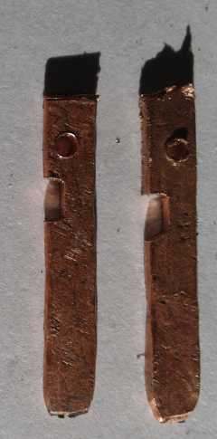
3D printed shells might hold straight pins, I finally decided to file a
notch in them that would be filled by a piece of the plastic. With a
hole to solder a wire into they ended up per the image, and the first
plug also as shown.
It was a little smaller in all dimensions than the CAT
plugs. One might coerce one into a CAT socket, but the pin spacing was
a little smaller, and the blades twice as thick, so it wouldn't be easy.
 But I wasn't
sure yet that this was the final size. I
still had to make a socket, and the shells inside to receive the plug
pins had to be far enough apart not to be in any danger of touching
each other. Now, what were those going to look like and how would I
make them?
But I wasn't
sure yet that this was the final size. I
still had to make a socket, and the shells inside to receive the plug
pins had to be far enough apart not to be in any danger of touching
each other. Now, what were those going to look like and how would I
make them?
The simplest thing to do seemed to be to flatten a piece
of wire (#14), make shallow bends in both ends to guide the pin in and
pinch it, and then to fold it in half over a pin. The pin at the fold
made sure it would fit over a pin for its entire length, provided a
space to solder a wire into, and made the bend in the copper more
gradual so it wouldn't break. The resulting sockets seemed
satisfactory, the pins sliding in and holding with a good grip.
The fold was far enough away that it wouldn't loosen if a slightly
thicker pin was inserted. (Unlike those crappy Pico connector sockets,
which plague my CAT connectors. They bend and loosen and then connect
so badly that one once left my first electric Mazda RX7 EV dead on the
street and not knowing what was wrong!)
 So next they needed
a shell. Back to OpenSCAD and the 3D
printer... I designed the socket shells and printed a couple, by now
rather late at night and after a small altercation with a loose drive
belt on the "Y" axis, caused by some loose nuts in the printer. The
first version didn't quite hold the copper pieces right. There wasn't
room for them to open a bit to receive the plug pins. The second
iteration was successful. The plug and socket seemed to mate and hold
well. After a couple of dozen insertions, they were looser but still
okay. Anyway they seemed much better than the Pico sockets.
So next they needed
a shell. Back to OpenSCAD and the 3D
printer... I designed the socket shells and printed a couple, by now
rather late at night and after a small altercation with a loose drive
belt on the "Y" axis, caused by some loose nuts in the printer. The
first version didn't quite hold the copper pieces right. There wasn't
room for them to open a bit to receive the plug pins. The second
iteration was successful. The plug and socket seemed to mate and hold
well. After a couple of dozen insertions, they were looser but still
okay. Anyway they seemed much better than the Pico sockets.
Of course it's a nuisance to have to make pins and
receptacle pieces instead of buying them and pulling them out of a box.
But it won't matter once they're in production. Some machine can spit
out any size and shape you want. With the CAT 12 VDC plugs and sockets,
I was trying to make something similar to AT fuses with a twist,
expecting to find existing blades and receivers for them. (But the
blades only existed on the fuses themselves.) With the HAT 36-40 VDC
ones I was
working for "optimum" instead of some nebulous "backward compatibility"
with existing hardware parts.
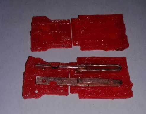
Plug & socket with pins, mated together
 Trying to fit the wires.
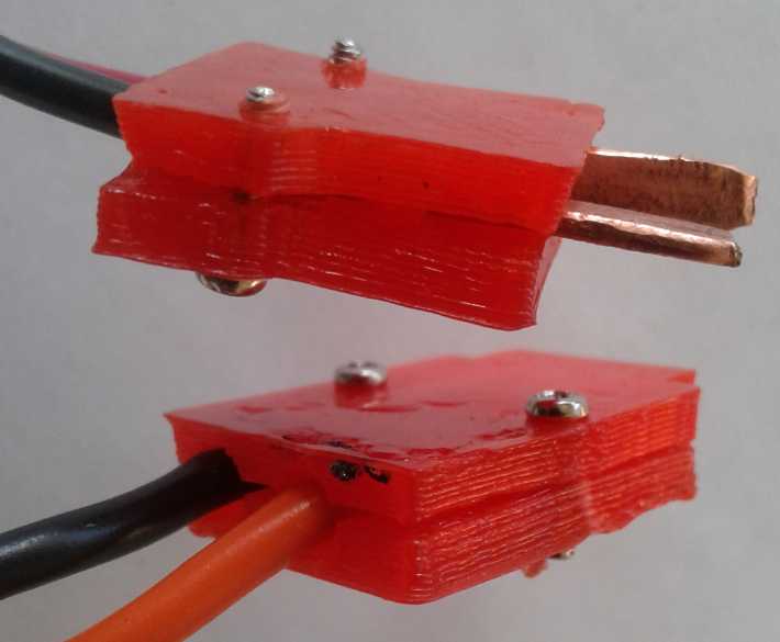 I found that when the wires were
added, the housings were
a little too small. I used the ones I made, but I'll expand the
housings a little to leave a good space for connecting the wires
inside. Once that's done I'll put the OpenSCAD [text] files for the
housings in TE News or link to them. Hopefully with wall plates as well.
I found that when the wires were
added, the housings were
a little too small. I used the ones I made, but I'll expand the
housings a little to leave a good space for connecting the wires
inside. Once that's done I'll put the OpenSCAD [text] files for the
housings in TE News or link to them. Hopefully with wall plates as well.
And I thought of a new design of sockets and wall plates.
The front end of the socket will be the wall plate itself. The blade
receptacles will be inserted into the plate, then the back ends will be
slipped on and screwed in to hold everything in place. These will look
much nicer, with the whole plate being the underside of the print, flat
against the printer bed. (I'll probably do a CAT socket plate that way,
too.)
New 3D Printer
My "ReprapPro Mendel" 3D printer is a commercial kit
version
of the original RepRap ("Replication Rapid") 3D printer made by the guy
in
London that started the whole genre - that first made possible low cost
home manufacturing of custom plastic parts. At the time, I was
astonished that one could buy a kit and put such a manufacturing tool
together for under 1000 $. It took me two weeks to assemble it, as I
recall. But with the ongoing intermittent troubles I
had long been having with the extruder head (even tho they were just
"minor" wiring problems, but in one small part of the printer but where
it was too hot for reliable solder connections), my confidence in the
printer continuing to
work reliably has become much diminished. And the pieces come out
pretty
coarse. I had been unable to make plastic battery electrode pockets the
way I wanted because the holes came out too big and let powder fall
through.
I also knew that there were new models out there even some
years ago. Especially useful would be those that had an enclosed and
heated printing space, which as I recalled was supposed to result in
much less warping of large parts.
I looked on line at AliExpress.com and found hundreds of
choices of seemingly dozens of models mostly for about 300 to 500 $
Canadian. WOW! There were lots of duplicates, the same machines being
sold by different stores (and even multiple listings by the same store
with somewhat
different prices listed and different shipping rates so that they all
ended up about the same anyway - Huh?), but it was still an astonishing
variety. For
those sort of prices it seemed almost foolish to continue to rely on my
old coarse-extrusion beast that warped larger pieces as it printed
them, when I could surely get something already assembled and reliable,
that works better and makes finer parts, for such a low price. Maybe I
could make the printed plastic battery electrode pockets I had tried to
make a
few years back?
I ordered one, an "ANYCUBIC 3D Printer I3 Mega Large Plus
Size Full Metal TFT Touch Screen". (I didn't see any that had the
heated print space. There was one that was enclosed, by the same
company, but it didn't say it was heated, so it would mainly just be
harder to
access things with no apparent advantage.) Perhaps the tendency to warp
had been improved without heated ovens? At 210 x 210 x 300 mm, it
had about the same bed size and could print taller than the RepRap. It
was also single extruder, where some could do colors or "wash-out"
extrusions. The latter allow for printing above spaces that turn into
large voids, without sagging, by putting the printed part in water and
dissolving away the water soluble parts after printing.
In addition to plastic extruding printers, there were a
couple of photo-laser resin-hardening printers for similar prices.
Those cost a fortune - tens of thousands of dollars - back when I was
first doing 3D printing!
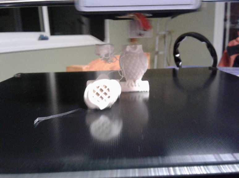 The machine
arrived on the 26th. I put it together and
tried the supplied test print. The detail was, as hoped, much finer
than the RepRapPro Mendel, with the extruder laying out a much finer
bead of plastic. But there was a tradeoff: The printing was also much
slower. It took 80 minutes to print the two little owls. And they were
tall on fairly small bases - one fell over 3/4 of the way through. The
bead came out into the air, making a mess. Yowr! But the other one was
still printing, so I let it continue. A couple of beads of plastic then
caught on the other owl and the first owl's head started printing
again, right in mid air! It moved around too much to make a good print,
but at least it stopped plastic from spewing everywhere. The second owl
came out very nice.
The machine
arrived on the 26th. I put it together and
tried the supplied test print. The detail was, as hoped, much finer
than the RepRapPro Mendel, with the extruder laying out a much finer
bead of plastic. But there was a tradeoff: The printing was also much
slower. It took 80 minutes to print the two little owls. And they were
tall on fairly small bases - one fell over 3/4 of the way through. The
bead came out into the air, making a mess. Yowr! But the other one was
still printing, so I let it continue. A couple of beads of plastic then
caught on the other owl and the first owl's head started printing
again, right in mid air! It moved around too much to make a good print,
but at least it stopped plastic from spewing everywhere. The second owl
came out very nice.
With that speed I can imagine my 5 hour prints of 10
D-cell battery cases might go to 15 or 20 hours. I won't be throwing
the Mendel out yet after all!
I noted that there was a new and doubtless useful feature:
the [noisy] fan blew air through a small slot directly onto the work
where the plastic came out of the extruder. (small black 'hood' duct
under extruder box) This would rapidly cool the
plastic. Perhaps this was the simple replacement for the heated oven,
which was thus rendered obsolete? I'll know if I print some larger
things with ABS and they don't warp.
Another improvement was that the glass printing bed/table
has some texture and doubtless a superior grip to the smooth glass of the Mendel. (That
didn't seem to save the owl.) And it came with a spare extruder - the
very part I was having trouble with in the Mendel. If I had a spare
extruder for the Mendel, maybe I wouldn't have bought a new
printer now?
Next I'll have to delve into the slicing and G-code
software on the AnyCubic3D.com website. It would be too simple if I
could use the same stuff as for the Mendel. (...or are those on the
supplied USB stick or SD card?)
Better LED
Lighting
Ceiling Panel Lights
On the 1st I ordered
another 3 of the 300x600 mm panel lights because they seemed so nice,
and because I could so easily use them with the 36-40 volt DC power
system if the AC is off, since they were full brightness at about 38
volts.
On the 3rd I
mounted one in the ceiling of the dining
area, replacing a ceiling-flush fluorescent light. The dining area had
three of them and I removed the tubes from all of them. In theory I
replaced 6 old fluorescent tubes of 40 watts - 240 watts - with a 24
watt LED flat panel light, and it was just as bright. In practice three
of the tubes were 34 watts instead of 40, and one of the fixtures
wasn't lighting up anyway, so it was more like about 150 watts I
replaced - "only"
a six times power reduction.
Taking out the fixture with it freezing outside, cold air
blew through the hole in the ceiling, as it turned out the fixture
covered an uninsulated hole
into the unheated attic. I had to put in some wood to screw gyproc to,
insulation, and then gyproc with the cold air blowing down. Brr! (Now
that I know that, I really must do in the other two fluorescent
coldness holes!
They say one square foot uninsulated leaks as much heat as ten square
feet that are. Or was it even worse than that? This was almost 12
square feet uninsulated with cold-conducting metal fixtures - 8 more to
go.)
The LED light is 4000°K color temperature "natural
white", instead of unpleasant fluorescent "cold white" with its huge
retina-harsh mercury vapor spectral spike. Another bonus was
elimination of balast transformer hum. The only drawback was that the
light was now concentrated in one panel instead of spread out across
the ceiling. I may put up a second panel.
I put the power supply over the gyproc in the wiring and
put the short DC power cord through. I can easily access the plug and
change it to 40 volt DC power any time that seems useful (power is out
or ?) It will of course be easier if I get the 36-40 volt plugs and
sockets designed and make some, then run an actual 40 volt wire to a
wall socket, and make an adapter cable with about a 5 ohm current
limiting resistor to go to the light. There's the theory (it's
perfect!) and then the practical (it will take some work).
It wasn't until the 22nd that I got some drywall compound
and tape to "niceify" the ceiling.
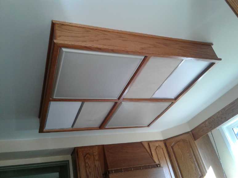 On the 8th I
realized that the panel lights would fit
right into the "wooden box" light fixture
in the kitchen ceiling. So I disassembled the two 2-tube fluorescent
lights inside it (two 40 and two 32 watt tubes: 144 watts) and wired up
the LED power units. (I left the bodies of the fluorescents up rather
than disconnect the wires and pull everything out. They're doing no
harm and no one will see them in the closed box.) With two 24 watt
panels it was very bright. Even with the morning sun shining through
the window they brightened up everything except direct sunlit surfaces.
Dark shadows were vanquished. There would never be another dull day in
the kitchen! But with 48 watts I've only reduced power consumption
threefold. With 5, 8 and 17 watts LEDs, I've been leaving lights turned
on all over the place. Gosh, 48 watts is worth turning them off for if
I'm not in the kitchen!
On the 8th I
realized that the panel lights would fit
right into the "wooden box" light fixture
in the kitchen ceiling. So I disassembled the two 2-tube fluorescent
lights inside it (two 40 and two 32 watt tubes: 144 watts) and wired up
the LED power units. (I left the bodies of the fluorescents up rather
than disconnect the wires and pull everything out. They're doing no
harm and no one will see them in the closed box.) With two 24 watt
panels it was very bright. Even with the morning sun shining through
the window they brightened up everything except direct sunlit surfaces.
Dark shadows were vanquished. There would never be another dull day in
the kitchen! But with 48 watts I've only reduced power consumption
threefold. With 5, 8 and 17 watts LEDs, I've been leaving lights turned
on all over the place. Gosh, 48 watts is worth turning them off for if
I'm not in the kitchen!
I was finally rid of all the fluorescent light tubes
except in the garage. I may order yet another set of three panel
lights. Tubes of all types, even tungsten light bulbs and fluorescent
tubes, are quickly becoming a thing of the past, and as discovered by a
couple of friends, LEDs compared to
tungsten bulbs are probably a power savings equal to the extra power
used by the coming of electric cars.
Even with the sun coming through the window, the
kitchen is much brighter with the panel lights on!
Screw-In Plant Grow Lights
 Even less connected to the solar system, I'll mention here that I got
five 120 VAC plant grow lights that screwed into ordinary North
American light bulb
sockets (officially named "E27" sockets). I had never heard of such a
thing, but Jim Harrington pointed me to a Chinese on-line store he
found called "BangGood.com" ("Good bang for your buck!") that had them.
Since I have the "indoor LED garden" with screw-in lights, this seemed
too convenient to pass up.
Even less connected to the solar system, I'll mention here that I got
five 120 VAC plant grow lights that screwed into ordinary North
American light bulb
sockets (officially named "E27" sockets). I had never heard of such a
thing, but Jim Harrington pointed me to a Chinese on-line store he
found called "BangGood.com" ("Good bang for your buck!") that had them.
Since I have the "indoor LED garden" with screw-in lights, this seemed
too convenient to pass up.
Since they were specifically for grow lights intended to
cast their
light straight down, they didn't have to cast light to the sides or fit
into the small profile allowed by most fixtures for
tungsten/incandescent bulbs. This allowed large flat lighting areas
pointing down, and with more cooling capacity provided by air slots in
the housings. Imagine almost up to a CD/DVD size with lights on one
face. Some types were out of stock, but I got five nice ones. I
appreciated that the largest ones had a few white LEDs to avoid that
weird look resulting from having only red (~670 nm) and blue/violet
(~450 nm) light colors. They were 30 watts, with 290 LED emitters: 190
red, 75 blue, 15 white, and 10 warm white. The smaller ones were 9
watts with 200 emitters: 166 red, 34 blue. (I thought grow lights were
supposed to have more blue than red. Obviously I'm mistaken.) Some of
the "too small" cooling slots in the 9W ones were blocked with remnant
plastic. The 30W ones had bigger slots, but of course they made more
heat too.
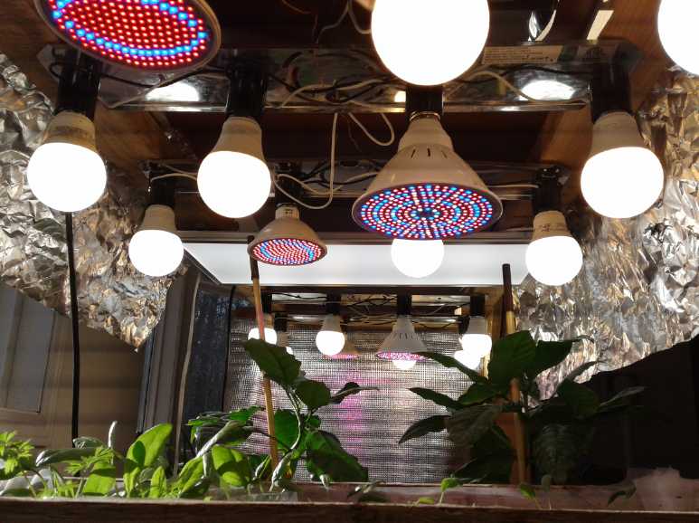 The screw-in plant lights installed in the
"Indoor LED Garden", replacing some of the regular LED "bulbs". I've
moved
The screw-in plant lights installed in the
"Indoor LED Garden", replacing some of the regular LED "bulbs". I've
moved
the whole thing into the livingroom where it's warmer. (Bonus: The sun
also comes through the window to the left.)
Note the horizontal strobe lines in the foto, indicating that at least
some of the lights actually flicker on and off at high speed.
(I've been remiss in my plantings:
Plants so far are just starting spinach and carrots. The lettuce didn't
come up.
Behind are 3 small coffee trees someone gave me. They didn't seem to
like the cold kitchen.
Anyway my confidence level that I won't have to buy coffee "beans"
(seeds) any more is quite low.)
A second box of E27 grow lights has yet to come. And I had
ordered a
few more still, but some were out of stock and I got a refund. At first
I thought I might order more to sell locally, but after an hour I found
both types run quite hot, so I think I'll wait a year and see how many
are still working.
CNC Plasma
Cutter
A video suggestion
showed up on youtube, 5 Incredible Machines For Manufacturing at
Home #2.
In the middle of it, an ad cut in. It was for an
"affordable" CNC plasma cutting table. That was interesting enough that
I didn't (at the time) watch the rest of the "real" video.
The table was 1500 $US; nice! But that didn't include the
torch. If I bought it all I'd be into it for over 3000 $C.
The plasma
cutting torch used with the table seemed very good. It seems to me it
makes obsolete and replaces the
pulsejet steel cutter I had started making but never finished in about
2010 or
so (see some early issues of TE News). The cuts are said to be quite
clean - probably better than the pulsejet would have been.
I could say "Just as well I never finished it", except that I could
have
been using it all this time with my own CNC drill router mechanism
instead
of sending my designs off to be cut by abrasive waterjet.
The plasma cutting torch makes an arc to the grounded
workpiece like
a welder, but compressed air blows the arc right through it, making it
cut the metal sheet or plate. I didn't know about this technology. It
makes nice, clean cuts through thick steel plate. I think I'll make the
"water bed" with metal slats similar to the CNC unit shown, to use with
my own CNC router table. (still not wired up and running - yet. But
I've ordered a part for it.)
I phoned
the maker about the torch and they said Princess Auto was a dealer, so
I
went there. They had many
different units - the cheapest at 600 $ and more around 1000 $ and up.
I decided to pick a 120 volt torch - easier than wiring
up a 240 volt outlet and then being restricted as to where you could
use it. With my shop being attached to my house, if one burns down they
both
do. I prefer to do welding type stuff outdoors. The torch arrived on
the 28th.
I have the CNC
router that I traded when I moved up here,
but I
don't have it running yet. Assuming I do get it going, can I use
it for the plasma cutter as well as the router? The big thing for that
would be to make a deep bed for shallow water that holds the metal
plate and can take the abuse of the torch, without damage to the
regular table underneath. That could save a lot of money. Let's see...
the place that makes the plasma cutter table sells just the bed as a
replacement part. (The upright bar supports doubtless do eventually get
full of cuts.) Would it fit on my table, and could I just set or clamp
it in place? That might solve the problem without buying a whole second
CNC machine. And my table has a "z" axis (torch can move up and down as
well as "x" and "y" travel around the work piece), so in that respect
it's actually better than theirs.
The more I looked into
getting the table running, the more I think
all I need is a USB to "parallel printer port" adapter, to make cables
to connect the stepper motors, and "Mach 3" or "Linux CNC" software.
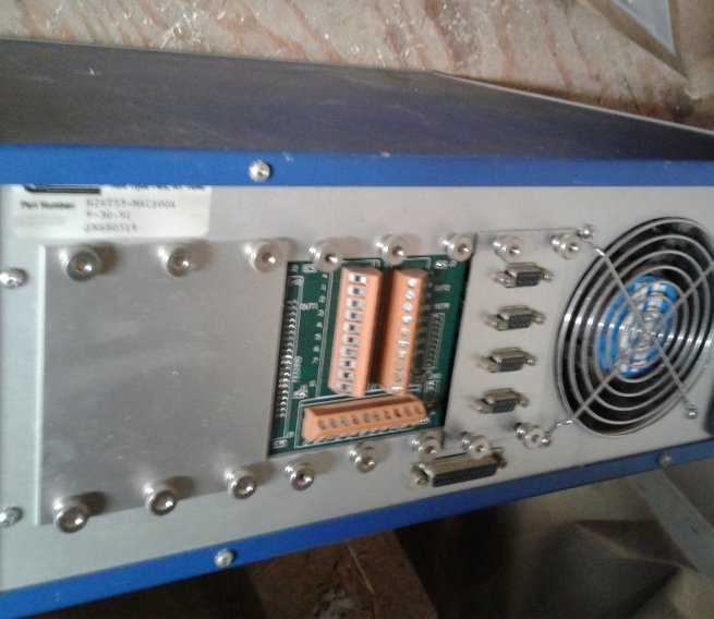 The DB-9 and DB-25 plugs on the back of the
table's very old
The DB-9 and DB-25 plugs on the back of the
table's very old
controller seem to be just the same as on the newest ones! Yay!
Extending My
Solar Power System some more
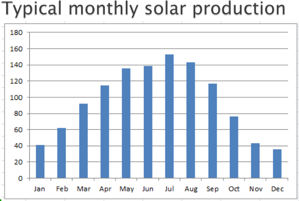 Here is a
chart that shows why so much solar power is needed at higher latitudes
if one is to be independent of the power grid all year. In the winter
when the most power is needed, the least is available. This chart shows
a difference of 4 to 1 between July and December. The higher the
latitude, the more pronounced this seasonal difference is.
Here is a
chart that shows why so much solar power is needed at higher latitudes
if one is to be independent of the power grid all year. In the winter
when the most power is needed, the least is available. This chart shows
a difference of 4 to 1 between July and December. The higher the
latitude, the more pronounced this seasonal difference is.
The other problem with the timing of solar power is that
production craps out just before everybody fires up the kitchen to cook
supper, turns up the house heat, and turns on the lights and computers
for the evening. Again - depending somewhat on season - the power isn't
available when it's most needed.
Canada stretches across several times zones. I wonder what
the practicality is of sending solar power east while it's still
afternoon in the west, to power the more easterly dinnertime peaks?
 Here are maps showing average hours of solar insolation over an average
year the province of BC, and all of Canada. Maps are of course
available on line for other areas. There are about 8766 hours in a
year. Of course half of them are night leaving 4383, and the sun is at
angles below 45° (even at the equator) for half the day, leaving a
maximum of 2191. Then there are the days of clouds and rain and snow
further reducing the solar input. I knew the west coast was the
cloudiest place, but I was surprised to see that the desertous Okanagan
(south central) doesn't get more sun than it says it does. I'm also
surprised that the entire west coast is smeared with the same color.
They have glossed over a lot of important detail.
Here are maps showing average hours of solar insolation over an average
year the province of BC, and all of Canada. Maps are of course
available on line for other areas. There are about 8766 hours in a
year. Of course half of them are night leaving 4383, and the sun is at
angles below 45° (even at the equator) for half the day, leaving a
maximum of 2191. Then there are the days of clouds and rain and snow
further reducing the solar input. I knew the west coast was the
cloudiest place, but I was surprised to see that the desertous Okanagan
(south central) doesn't get more sun than it says it does. I'm also
surprised that the entire west coast is smeared with the same color.
They have glossed over a lot of important detail.
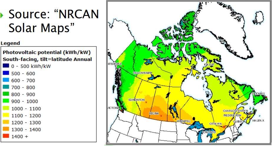 Canada-wide map showing that lakes must be the
worst places to put solar panels.
Canada-wide map showing that lakes must be the
worst places to put solar panels.
The highest latitudes may
have as much solar potential as farther south, but it would be entirely
seasonal, the sun disappearing for the whole of the winter months above
the arctic circle. And I'm sure much of it could only be realized if
the panels rotated, since the summer sun circles the sky. I wouldn't
want to live much farther north than where I am, about 53°. With
the 23° tilt of the Earth's axis, in midwinter the sun is only
14° above the horizon at noon. That improves to 60° in mid
summer. The improvement in solar power from the start of February to
the end has been apparent, although the especially sunny days near the
end of the month have accentuated the effect.
By the end of the month my own 2830 installed watts of panels were
putting around 7.5 KWH/Day into the grid.
7500 WH / 2830 W = 2.65 KWH/KW
2.65 KWH/KW * 365.25 Days/Year = 968 KWH/Year per KW capacity.
That's right in the "annual average" rainge - at around the end of
February. They'll do substantially better in the summer. Will it
average the average over a year... or do better? We won't know this
month!
How many watts are those
panels, again? Never full nameplate power:
75% seems to be a realistic figure
I knew that I never seemed to get close to full rated
power (892 watts) from my earlier solar panel system in Victoria even
in the best conditions. 600 or 700 watts seemed to be "as good as it
gets", but I didn't entirely know why.
On the 5th I looked again at the datasheets for the Hanhwa
"305 watt" panels when a potential customer wanted to know the
dimensions. Usually I have not had datasheets and have been going
simply on the sticker on the back of the panel. And until now even
seeing them, I had glossed this over: The nameplate rating is based on
1000 watts of sunlight per square meter. That would probably occur with
the sun
directly overhead of the panel and straight on, on a very clear day. It
is also based on 25°C operating temperature. Unfortunately, the
panels being dark blue or black, they get warm, and they are less
efficient at higher temperatures.
So a second set of wattages for more typical conditions is
given below the first ones. In these just 800 watts per square meter is
assumed - "NMOC" at "NMOT" - "normal module operating conditions" "-
temperature". Instead of 305 watts it lists 227.6, with slightly lower
voltage and current. (800 watts probably accounts for normal and
typical atmospheric moisture, dust and conditions, and going through
more atmosphere at some angle unless the sun is almost directly
overhead.)
The ratio 227.6/305 is 74.6% ~= 75%. If we apply that to
250 W panels we get 187 W. So the four panels (the ones on grid tie
inverters when I wrote this), by nameplate 1110 watts,
would more realistically give around 2(187)+2(227.6) = 830 W in the
vicinity of midday on a warm sunny day.
Panel Efficacy: Crap in winter as expected
As the first frozen days of the month went by I checked on
the performance of the grid-tie system. Of course the days were still
short, and the long shadows of the trees still shaded the collectors
all morning (until about 1/2 an hour after solar/real noon) and in late
afternoon, so the period they were working well
even when it was sunny was pretty short - maybe 12 to 4 PM. Then, the
~1100 rated watts panels put only up to ~500 watts into the mains. 500
watts for 4 hours is 2 Kilo Watt Hours (KWH) - if that. With 50 or 100
or 22 watts
at other times through the clouds and tree shadows, perhaps 2 KWH/Day
is a good if very rough figure. (Later I started using actual meters. 2
KWH/Day at this point was probably on the optimistic side.)
I had a 500 watt heater in
the travel trailer to keep it from going moldy and a 250 watt one in
the Leaf to keep the batteries warm, mostly going 24 hours a day. So I
was using 18 KWH per day just
for those, and with bedroom heat and the electric car itself and
everything else as well it added
up to probably 40. (It was 38 KWH/Day on my last bill, with no panels
connected.) So it was only making 5% of what I was actually
using. But in an extended power failure, I can switch between grid-tie
and "charge batteries/run inverter", and the difference between 5% and
0% of a usual amount is "have" and "have not". 5% means you can have
(LED) lights at night, plug in your fridge and freezer a couple of
times a day to keep them cold, charge your cellphone and your tablet,
and run your computer a bit.
But it hadn't rained much for a while either, so I suppose
the lake making hydro power was too low. Or it just didn't have the
capacity. When I drove south toward town, I could see the diesel
generators across the water in Sandspit bellowing clouds of smoke that
obscured the land to the west, to make the electricity for hundreds of
homes all with their heat turned up. (The first time I saw that, I
thought some building must be burning down over there!)
Of course, that's in the worst of the winter - the "second worst
case scenario". (Worst case is when it's also heavy overcast &
raining a lot or snowing, and one gets almost nothing.) When it's much
above freezing the heater in the back of
the car isn't on, and I drop the trailer to 250 W. Bedroom heat uses
less. And of course the output from the panels improves dramatically
toward summer. The spruce tree causing the most winter shade on the
roof and panels before noon may be dying and if so may need cutting
down in another year. That would be a plus for the solar power.
(But please, not until I've finished milling the logs from the trees
already cut down, and cleaning up all the branches!)
To jump the story timeline, by the sunny weather at end of
the month and with 10 panels working, and with lowered demand from
turning heaters down or off, reading the solar meters I hooked up and
the house power meter indicated solar was making around 25% of the
total power. (Including the electric car.) As spring progresses the
figures will get better.
Except when it's cloudy.
Still More Solar Panels - and Monitoring Output
Any little bit generated by any renewable means was at
least some small mitigation of diesel exhaust. I could certainly put up
a couple more solar panels and
another grid-tie inverter... and get another KWH per day.
I started considering putting a couple up on the east
roof, instead of or in addition to more on the south. It would get more
sun in the morning. I set a ladder up so I
could look onto it. It was steeper than I thought and the house was
actually turned 21 degrees clockwise from north, so advantageously it
faced
slightly south.
And, notwithstanding the trees across the highway delaying the early
morning sun, it got a lot more sun than I had realized. In the morning
it
was less in the shadows of the trees that plagued the panels on the
south roof in winter. (And the north end was in just the right place
for solar hot water, above my rainwater barrels.) But the trees shaded
it in the middle of the day, the best time, and I decided it would just
be a place for the hot water collector.
The most obvious thing to do would be to cut down the row
of four trees. Would I miss them? I'll have to think about it once I've
dealt with the ones already down with 1/2 the lumber still to be cut.
The other advantageous thing to do would be to put up
panels on the roof covering the travel trailer. It was south of the row
of spruces, and some observation showed that while not immune to tree
shadows, it appeared to get more sun than anywhere else.
At around freezing it was too cold to work outside except
in shorter bursts (or I'm
just a wuss - most of Canada was much colder), but the installed panels
gradually improved. By the 11th it hit 600 watts.
I started to realize I had probably made a mistake about
the 1000 watt grid tie micro inverters that only seemed to put out
half. If two of my panels had had a bad connection in the original
configuration last summer, that would create almost the symptoms that I
had. Why I didn't think of this last summer I can't imagine. I looked
on line and couldn't find any complaints about the inverters. Hmm! Now
I had ordered a fourth one, which I started to suspect I probably
didn't need. I didn't put the idea to the test for a few days.
The batteries didn't need to be charged all day for the
little I was using the DC lines. On the 16th I installed the third
micro inverter and ran the wires from the third pair of panels to it.
But I also connected the battery charge controller/DC to DC converter
to the same panels. If I switched the inverter on and the charge
controller off, the third pair of panels could go to the grid, or I
could switch the charge controller on and the inverter off. If they
were both on, they didn't seem to co-operate very well but the next day
they seemed okay.
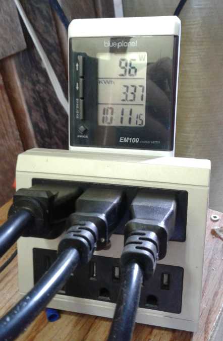 Late in the
afternoon, rooting through my "electrical crap" box, I discovered a
"Blue Planet Energy Monitor, EM100". I have no idea where it came from.
Either I bought it and forgot about it, probably long ago, or else
someone gave it to me and I took no notice. Unlike the Canadian Tire
ones, it took batteries (huh?) and it also seemed to work fine in the
reverse direction, so I could leave it plugged in to monitor the power
being made by the panels. (It didn't seem to distinguish between "load"
and "generate" as long as current was flowing. The three inverter cords
were plugged into a 6 outlet strip to the monitor only because I
couldn't find a proper 3-outlet one at the time.)
Late in the
afternoon, rooting through my "electrical crap" box, I discovered a
"Blue Planet Energy Monitor, EM100". I have no idea where it came from.
Either I bought it and forgot about it, probably long ago, or else
someone gave it to me and I took no notice. Unlike the Canadian Tire
ones, it took batteries (huh?) and it also seemed to work fine in the
reverse direction, so I could leave it plugged in to monitor the power
being made by the panels. (It didn't seem to distinguish between "load"
and "generate" as long as current was flowing. The three inverter cords
were plugged into a 6 outlet strip to the monitor only because I
couldn't find a proper 3-outlet one at the time.)
The 17th was bright and sunny. The monitor said the 6
collectors and inverters were sending almost 1000 watts to the house
and grid at the best part of the day with all 6 panels (1612 nameplate
watts - IIRC: 265+265+240+232+305+305), and by the end of the day it
said 3.08 KWH had been sent out - that that much less had been needed
from the power grid. That was in spite of the tree shadows all morning
and in addition to using a bit for off-grid battery charging. I found a
manual for the monitor on line; how to reset the max watts and max
amps, kilowatt-hours and set the "overload" reading point (which I will
hopefully have no use for). While looking for that, on Amazon I found
many more power monitors, but none of them specified whether they could
be used to measure inverter outputs instead of loads.
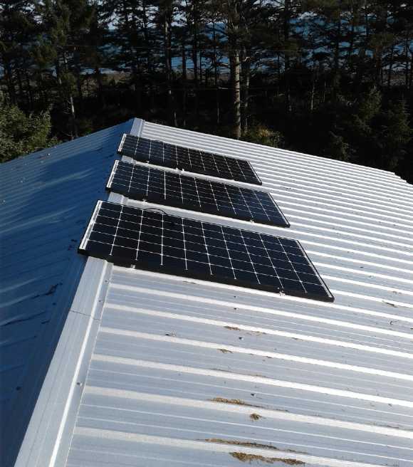 I also made
use of the dry, sunny day to put up panels on the roof over the
trailer. As I was putting up the second one, it occurred to me that if
the inverters really did 1000 watts, three panels rated in total 915
watts would be (even at 100% of rating) a good match for one inverter
there. I had the crate of
panels. I had everything set up and was working on the roof. There was
lots of room for more panels and it was the sunniest place. Why not?
Somehow I had fortuitously also made an extra set of brackets for
attaching another panel, so I only had to bolt them on. I got all three
panels up that afternoon. But I had to forgo doing the wiring that day.
I left the ladder tied in place. (Note the long winter shadows behind
the planels at this high latitude [53.4°N] even in February. In
December they would go all the way down the roof.)
I also made
use of the dry, sunny day to put up panels on the roof over the
trailer. As I was putting up the second one, it occurred to me that if
the inverters really did 1000 watts, three panels rated in total 915
watts would be (even at 100% of rating) a good match for one inverter
there. I had the crate of
panels. I had everything set up and was working on the roof. There was
lots of room for more panels and it was the sunniest place. Why not?
Somehow I had fortuitously also made an extra set of brackets for
attaching another panel, so I only had to bolt them on. I got all three
panels up that afternoon. But I had to forgo doing the wiring that day.
I left the ladder tied in place. (Note the long winter shadows behind
the planels at this high latitude [53.4°N] even in February. In
December they would go all the way down the roof.)
If the grid tie microinverters were actually 1000 watts,
three panels on the trailer roof should result in around 600 watts to
the
grid on a sunny day even in February. Now I was going to hook them up,
so that would be the test.
The next day (18th) I ran the wires. Where the AC power
cable went into the trailer there was lots of room for more cables
(AHA! So
THAT'S where the mice were getting in!) so I poked them through into
it. Better to have the inverter indoors! I took one from the garage and
hooked it up. Sure enough, it got up to about 500 watts (over 4.2 amps)
"to the grid"... really, to the 500 watt heater nearby on the floor. So
presumably very little current was flowing either way in the 100'
extension cord that powered the trailer. That was more than I had got
out of the inverter last summer, so the low power back then must have
been a bad connection
- probably one of the two pairs of panels wasn't contributing. I should
have suspected that might be the problem, but I never did. Oops, my
bad! Well, c'est la vie!
I wished I had another "Blue Planet" power monitor for the
trailer. I eventually found the "outlet tripler" with the taped off
blades and late in the afternoon the male-to-male cord, and I plugged
in a Canadian Tire power monitor, backwards. Now I could keep track of
how much power was being made at both sites.
The terminal screws in the inverters were so short one
couldn't get three flat wire lugs connected and not even two thick
ones. If I still have one minor complaint I wish the terminals were at
least 1/8" longer. (Having found this problem, I used only the thinnest
lugs at the trailer, wired two panels on one cable to one pair of lugs,
and got all three onto each terminal.) How to connect the disconnected
panels to the other inverter with the other two old panels? I ended up
with the connector of last resort, alligator clip test leads. With the
same four panels as last summer, this one also put out over 500 watts,
again proving that these inverters would do over 420 watts and that I
must have had a bad connection in the wiring.
At the peak time with the sun lined up south, the house
panels hit 1072 watts and the trailer well over 500 for a total of
about 1600 watts. Altogether the panels were rated 2527watts. Using the
"realism factor" of 75% gives about 1900 watts. Considering the roof
angles weren't optimum for the low sun, that seemed quite good. In
spite of increasing cloud in the afternoon and the disconnected panels
at some times while I was working, the panels on the house made about 2
KWH.
And on that day finally the weather started to warm up
(reaching about 5°c). The snow, frost and ice mostly melted away,
and I could turn on the tap on the water barrel and get rain water
again. I unplugged the heater in the car and turned the trailer heater
down from 500 to 250 watts. Using 12 KWH a day less is as effective as
having many more solar panels!
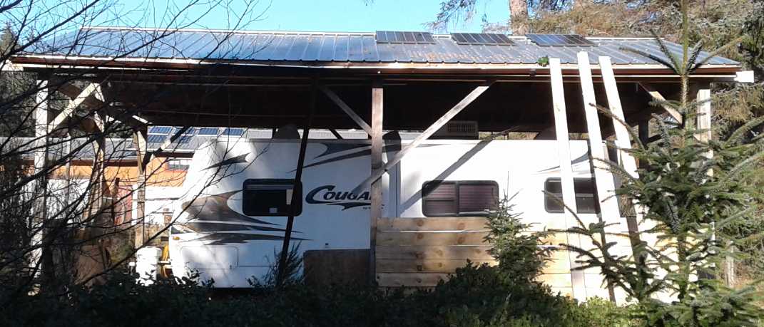 I used the 3 leaning boards as a "ramp" to haul
the panels up with a rope.
I used the 3 leaning boards as a "ramp" to haul
the panels up with a rope.
The trailer roof got the least tree shadows of anywhere on my place.
(The 6 panels on the house roof are just visible behind, just below
this
roof.)
Production per panel improved
noticeably day by day as the sun got higher and the days lengthened.
Before 10:30 AM on the 19th, when at the beginning of the month the sun
was just up, the combined 9 panels had already made 1/2 a KWH and
charged the batteries. By 11:15 the 3 panels over the trailer were
doing 520 watts, but the tree shadows were reaching the 6 on the house
and they were down to 430 watts, and by 11:30 in light haze the figures
were 435 and 200. I should probably have put all the new panels on the
trailer cover roof! (One more panel would theoretically exceed the 1 KW
theoretical capacity of the micro inverter. If the inverter would make
so much or I used two inverters, 5 panels, 1525 watts rating, would be
the limit for one house breaker and the extension cord to the trailer.)
Then it clouded over and rained, but by 2 PM, the peak producing time,
the sun came out again for a little while. At that point the 3 panels
at the trailer were doing 500 watts and had produced 1.2 KWH. The house
was at 900 W, but with the 6 panels having been in the tree shadows it
had made just 1.3 KWH. By 3 PM it was raining again and watts were down
to 130 (trailer) and 230. The end-of-day total was 3.5 KWH. The 20th
was cloudier and the total was 2.9 KWH. With 9 panels fully employed,
production was at least 50% more and I was now using up 30 instead of
40 KWH per day.
So I was now making 10% of what I was using instead of just 5%. Except
for it not being December any more, the 21st was almost a "worst case"
day with heavy overcast and rain. There was a brief sunny break, but
the total collection for the day was less than 1.5 KWH.
I decided to
put one more panel over the trailer to fully utilize the inverter, and
did so on the 20th. I might have just done the trailer if I hadn't
already put two more panels on the house in January, but there seemed
to be little point to taking them down. The house production would
improve a lot when the sun got above the trees in spring.
I ran into a snag when I went to wire it. Ever since I
wired my house in the 1970s, and being involved in electronics, I had
saved any scrap of house wire or extension cord wire I ran across. Now
I had finally run out of longer pieces. I looked dubiously at a 17 foot
piece when I really needed a 40. Was I really going to have to buy
house wire after all these years? Well, maybe two 20s? I didn't want a
join outside, but anything was better than going to a store and buying
what had been free for so long. (I had to go into the store anyway, so
I looked. Yikes the prices have gone way up since the early 1980s!
(Wasn't 14/2 14¢ a foot? Now over a dollar in the local hardware!)
Apparently I have saved some money by saving all the wire I run across.)
Let's see... the 14-3 going to two of the panels (really
14-4: red+black & white+bare) had extra length (~40 feet) and I
hadn't cut it shorter yet. If I moved it from what were now the middle
two panels to the farthest two, the last wire could be shorter. Hmm...
probably everything would make it if the wires were rerouted to go in
through the ceiling vent instead of the trailer plug-in gland down at
floor level. And shorter wires is less losses. Figuring out that
subject:
#14 wire is .0025 ohms/foot. So if the
wire is 40 feet long that's .1 ohms. But there's two wires, + and
-, so .2 ohms. At the maximum of about 10 amps, that's 2 volts.
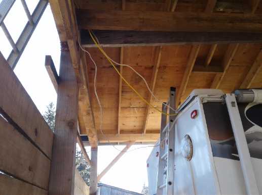 After all, at 33 volts a 2
volt loss is 6%. If one can trim 25% off the wire length... well, it's
small peanuts, but it might as well be done - saves on wire! (Then
there's the losses in the 100 foot extension cord to the trailer (#12
AWG, .0016 ohms/foot, so .32 ohms counting both wires.) once it's
converted to 120 VAC.)
After all, at 33 volts a 2
volt loss is 6%. If one can trim 25% off the wire length... well, it's
small peanuts, but it might as well be done - saves on wire! (Then
there's the losses in the 100 foot extension cord to the trailer (#12
AWG, .0016 ohms/foot, so .32 ohms counting both wires.) once it's
converted to 120 VAC.)
On the 23 I got up to the trailer roof and took a vent
cover off. Under the grille I could see some wires and the top of the
radiator coils at the back of the freezer. I cut away a bit of the
flimsy aluminum screen/grille and poked the panel wires down the hole.
Inside, I pried on a thin piece of 1/8" plywood mushboard at the back
of the cupboard over the fridge. It broke and I could see the wires
behind. I took a bent coathanger wire and pulled them out one at a
time. I clipped the long wire from the two farthest panels to similar
length to the others. They were then a good length to mount the
inverter on the wall next to the cupboard, where it would also be out
of the way of anyone using the kitchen in the trailer. Mounting the
inverters vertically on a wall gives convective ventilation and seems
to keep their cooling fans from coming on most of the time. It's
quieter and probably better for them.
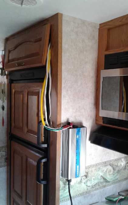 There were now
four 305 watt panels over the trailer - and connected - total nameplate
rating 1220 watts. Multiplying by the "realism factor" of 75% that
would be 915 watts, but the sun was still too low, too far south, to
hit the panels straight on. A while later there was a brief break in
the clouds, and the output went from 220 to 750 watts. That seemed very
good. (In fact, I never saw 750 again in February - 735 was about peak.
My surmise is that with the sudden clearing of the clouds, the panels
were still cold instead of warm - higher efficiency when cold.) Then
within
an hour the clouds cleared off. The house was doing exactly 1000 watts
and the trailer 735. Now there was some real electricity being made!
Those output figures proved to be the peak, but it continued strong
until the tree shadows hit all the collectors late in the afternoon.
There were now
four 305 watt panels over the trailer - and connected - total nameplate
rating 1220 watts. Multiplying by the "realism factor" of 75% that
would be 915 watts, but the sun was still too low, too far south, to
hit the panels straight on. A while later there was a brief break in
the clouds, and the output went from 220 to 750 watts. That seemed very
good. (In fact, I never saw 750 again in February - 735 was about peak.
My surmise is that with the sudden clearing of the clouds, the panels
were still cold instead of warm - higher efficiency when cold.) Then
within
an hour the clouds cleared off. The house was doing exactly 1000 watts
and the trailer 735. Now there was some real electricity being made!
Those output figures proved to be the peak, but it continued strong
until the tree shadows hit all the collectors late in the afternoon.
The next morning was sunny. It showed the stark contrast
between the 6 panels on the house in tree shadows versus the 4 in the
sun on the trailer: 85 watts versus 700 watts. With this all-morning
head-start, the trailer had produced more kilowatt-hours than the house
by the end of the day. Location is everything!
The inverter in the trailer was almost burning hot. Surely
at least 10% of the input was being converted to heat. But in the
chilly trailer, that's a plus! The cooling fan came on for a half a
minute occasionally, blowing quite warm air. It might have been 70 to
100 (?) watts of heat, but with the outdoors at about freezing it
didn't justify turning off the 250 watt heater. (So the panels
themselves were putting out 70 to 100 more watts than the output to the
power line indicated - over 800 rather than 735.)
I think I now have enough electrical generation to manage
an indefinite power failure except perhaps on the cloudiest days in
midwinter: enough to run fridge, freezer and maybe heat hot water
during the day, and keep good lights on at night. In the summer if it's
sunny I could probably also charge the Nissan Leaf with the slow
charger
around midday and run various other things. But I also want some other
solar panels mounted directly on the other electric vehicles, to
"trickle charge" them all day.
Other than not yet having new chemistry batteries to hold
generated power
for longer periods, the big flaw in my setup is that I still don't have
a way to run that 240 volt deep well pump to have regular house
water when the power is out. Perhaps I should get a 240 volt inverter?
I would still need to change the pump to plug in somewhere instead of
being hard-wired to the circuit breaker sub-panel in the shop.
From the 20th on I didn't reset the
meters, to keep a running total for a while. On the 24th I thought to
start recording the house electric meter as well so I could compare
what was being made to what was being used. Whatever the panels made
would have been added onto the house meter readings during the day if
they hadn't been there.
Day - house - trailer - day total KHW. (9 panels main load to grid -
small load solar battery charging not counted.)
(19th -
- - 3.5) - Reset meters to 0,
0 after reading them. - mixed sun and clouds
20th - 1.71 - 1.19 - 2.90 - cloudy with sunny spots
21st - 2.44 - 1.70 - 1.24 - clouds and rain. One short sunny period.
22nd - 4.34 - 3.00 - 3.20 - clouds & rain; may [must?] have been
sunny in PM while I was out
23rd - 6.94 - 4.86 - 4.46 - AM clouds and rain, PM clear & sunny -
wired up all 4 trailer solar panels in AM.
24th - 10.29 - 8.64 - 7.13 - [64430 - 6PM] sunny all day [Power
company's total consumption meter]
25th - 13.86 - 12.64 - 7.57 - [64452 - 1PM, 64454 ~6PM] sunny all day.
Recharged car PM.
26th - 17.20 - 16.61 - 7.31 - [64473 - 10 AM, 64473 5 PM, 64474 6 PM]
sunny all day (a few very light chemtrails?) I did some disconnections
on the house panels to test water heating with solar-electric (see
below).
27th - oops - oops - ~6.885 - [64497 - 10:30 AM; 64498 @ 14:40; 64500 @
17:00; 64502 @ 19:00] (bath & bedroom heat last night)
28th - 22.92 - 24.66 - ~6.885 - [1:30 AM 64507; 64519 @ 10:30; 14520 @
13:15; 14529 @ 18:00; 46530 @ 19:00] - sunny all day. Recharged car
after 3 PM. The hot water tank probably used 2/3 KWH or so and resulted
in a few disconnections of the grid tie inverters.
March 1st - 25.22 - 28.68 - 6.32 - [64548 @ 11:30 AM & 2:30 PM;
drove 87 Km before 2:30 PM, plugged in car. 64558 @ 6 PM... unplugged
car: Why not let it finish charging in the daytime tomorrow!] Sunny all
day. (The 1000 W panel set was mostly unplugged from the grid for the
hot water tank experiment.)
March 2nd - 27.70 - 30.78 - 4.58 - [64589 @ 1 PM; 64595 @ 4:30 - Drove
to
Charlotte, so charging car again from ~3:00 PM.] - Cloudy early AM (was
little point waiting to charge car?), patchy cloud later AM, cloudy PM
March 3rd - 31.67 - 35.11 - 8.30 KWH! - [64624@12:30; 64627@17:00] -
sunny all day
Once I started reading the house electric meter, it became
apparent that while the sun was out, little or no power was coming from
the grid (except when I was charging the car or drying clothes, etc).
In fact, it was more likely that some small amount was
going out into it but that the meter wouldn't run backward. It costs a
lot more for a "legit" wired-in net-metering installation, and it just
seems like too
much trouble. The inverters are much more costly and more wiring -
approved wiring - is required. In fact, do I remember right that an
installation has to have 10 KW nameplate capacity to qualify? If so 2.8
KW wouldn't qualify anyway.
I don't see how these inverters could
possibly be dangerous to power company employees. Either they're
working properly and won't transmit to the line if there isn't already
voltage there, or they will fail and blow a fuse (or, worst, burn up).
I'm saving the power
company 50 ¢/KWH if/when they're burning diesel, so I hope they
will at least look the other way if they notice. It's in the evening
and at night to heat my bedroom that I'm using a lot of power from the
grid. If I do my laundry and have baths in the early afternoon I'll
probably get more solar value. Maybe I can heat water in the greenhouse
and keep it going more of the year? But a few KWH isn't a lot of heat.
Another thing that became more apparent was that without a
cheap, efficient and reliable means of storing electricity (such as
dammed water that can generate power on demand, or my batteries if I
ever get them working well), solar power is most effective if the power
is used in the daytime when it's being generated. (Especially of course
if the power company isn't paying you for what goes out to the grid.)
Otherwise, hopefully without getting too carried away, the
biggest, most controllable loads such as hot water for laundry and
dishes (3 KW), running the clothes dryer (6 KW) and perhaps electric
car charging (1 or 3 or 6 KW), are best scheduled to be done in the
daytime. (I'm allergic to grass pollen. It makes me itch and raises red
"welts". It was a great relief when I
went to see an allergist and the last thing he said as I was leaving,
which lit my mind like a lightbulb - the most valuable advise ever:
"So don't dry your laundry outside on a clothesline.")
DC to DC Voltage Reduction
While looking for LED lights at
aliexpress.com , I found a simple little buck converter board, that is,
one that would efficiently reduce voltage from a higher DC level to a
lower. It had
a trimmer potentiometer for setting the output voltage to any desired
voltage
lower than the input. That seemed like a great idea for running LED
lights, especially 12 volt lights from a 36 volt source. The main
component was an XL4015 from XLSEMI, which was a single chip buck
converter requiring minimal external components: max 40 volts in, max 5
amps out, 180 KHz switching, and about 90% efficient at reducing 36
volts to 12 volts.
The "absolute maximum" 40 volt rating on the chip is
rather vexing (according to the datasheet, and the catalog page did
mention it), since a "36 volt" battery system can easily be above 40,
especially when it's being charged. I decided that it would just have
to work a little above its "absolute max". If they didn't start blowing
up at under 45 volts, they were keepers.
They arrived on the 23rd. The
next day I soldered a 12 V CAT click-lock socket on the output, but ran
into trouble at the input... because I hadn't finished designing the 36
volt HAT plugs and sockets yet. So I had to solder on alligator clip
jumper leads.
I plugged in a lamp and found the output was at 17 volts.
This lamp didn't seem to mind. It dimmed as I adjusted the screw down
to 13 volts. There was an annoyingly intense little red LED on the
board to indicate it had power. Otherwise it was perfect.
I had actually started on the the HAT plugs and sockets
earlier this very month, and on the 25th I finished designing, and
made, a plug and socket [see under "Other Projects"], which I applied
to the board on the 26th, powering it from the 36 volt solar batteries
and supplying the 13 volts to the socket in the living room.
Electric Solar Water Heater
I wanted hot
water from my rainwater barrels to the kitchen sink, and preferably to
have it independent of the power grid. Someone in a youtube video had
compared heating water with two (or three?) solar PV panels versus an
actual hot water solar collector.
On the 26th I decided I should try just connecting my
still uninstalled "under sink" hot water tank to some panel(s) and
filling it, and trying that out. I got wholly carried away hooking up
and
monitoring the water heating, for several days.
It must have taken close to two hours rummaging through
containers to find some fittings to connect the tank to a couple of
garden hoses. I could have driven to town and bought some in that time!
One of two fittings I had given to someone only two weeks ago was just
what I now needed. And I had to use iron-rich well water that turns
brown and stains, as the rainwater barrels were frozen.
I directly connected a pair of 250 watt panels to the
tank, disconnecting them from the grid tie inverter. I plugged in the
water heater and an old lamp cord with a 120 V plug on one end to an
otherwise unconnected duplex receptacle, and hooked the other end of
the cord to alligator clip leads to the panels. I took the following
readings:
Time: 14:15 PM (Note: clock here is 48 minutes ahead of the sun, so in
reality it was 13:28 PM. Latitude is 53.4)
Ambient air temperature: 3°C
Initial water temperature: 7.0°C.
Amount of water in tank: 15 L
Voltage: 32 V; Current: 2.9 A (93 watts)
Obviously the setup wasn't exactly taxing two 250 watt
panels. Then I had the thought that the 305 watt panels were wired
individually and also, being monocrystalline, had a bit higher voltage
so it would provide more power. Hooking just one panel to the water
heater still wouldn't be a big load for the panel. So I changed it. Now
the inverter system was only down one panel, and about 200 watts.
The single 305 watt panel gave this:
14:30 PM
Temperature: 10.0°C
34.6 V (Over a volt was lost in the cord, connections and alligator
clip leads. It was closer to 36 V at the wires coming from the panel.)
3.28 A (113 watts)
14:45 - 11.5°
35.0 V; 3.30 A (116 W)
15:00 - 12.8°
35.1 V; 3.35 A (118 W)
15:15 - 15.1°
15:30 - 17.0°
34.9 V; 3.25 A (113 W)
16:00 - 19.2° [Sun going behind trees]
16:15 - 19.1°
I decided to continue the test the next morning, the 27th. I don't know
what lowest temperature the water dropped to overnight as it was
already being warmed when I got to it. Obviously the tank loses heat
and takes power to keep water hot even if it the water isn't being used.
Air 2.5°C
10:15 AM - Water 17.1°C
34.6 V; 3.25 A (112 W)
11:45 - 19.3°
10.0 V; .95 A (9.5 W) - Panel shaded by trees
12:15 - 19.0°
11.1 V; 1.0 A = 11 W - still shade
12:45 - 19.3° (air temp 3°)
26 V * 2.4 A = 62 W - still part shade
13:15 PM - 23.1°
35.7 V; 3.35 A = 120 W - sun.
13:45 PM - 26.4°
35.0 V; 3.25 A = 114 W - very light chem trails
14:00 - 28.0
35.3 V; 3.3 A = 116 w
*** END 28.4° ***
On 'day one' in the sun, 35 volts raised the water
temperature in the 15 liter tank by 12°C in less than 2 hours. In 8
hours it should have been quite hot. For a kitchen sink water heater,
that seemed sufficient - it would get hot eventually. Being right under
the sink it would be almost instant hot water, and it didn't need to
put out a bathtub full to do dishes. Control was automatic: when the
sun went away, there was no power. But a dedicated panel just for this
small water tank and small watts would be a waste. Rather, it would be
best to just hook it up to the 40 volt DC solar/battery power that was
to be run to the house. At 40 volts it should be should be about 150
watts, which would heat somewhat faster.
I switched the tank onto the
40 volt solar DC supply at 2 PM on the 27th:
27th.
14:10 - 29.0°
38.4 V; 3.6 A = 138 W (The power level seems better. Heat that water!)
14:15 29.5 The DC power controller, now drawing over 160 watts, and the
grid tie inverter, were somewhat dueling over the power from the
panels, each unit hunting back and forth for the maximum power point,
which changed as the other unit changed its own settings. But it seemed
to be working.
14:30 - 31.8°
38.3 V; 3.65 A - 140 W (Voltage out of the controller was 40.0,
so 1.7 V line losses)
14:45 - 33.4°
15:15 - 37.0°
38.3; 3.65 = 140 W
15:45 - 40.4° (voltage is the same from our DC controller, so no
change, 140 W.)
16:10 - 43.0°
140 watts was btter than 115. 250 or 300 would heat
notably faster. The tree shadows started covering the collectors before
4 PM and output as usual dropped like a rock. Then of course I had to
unplug the tank to prevent it from draining the batteries. The water at
43°C (109°F) was just about verging on "hot". Seven degrees per
hour was an okay temperature rise if one wasn't using much water. What
would it be like in actual kitchen sink use?
About that time it occurred to me I could use one of the
programmable up-converter controllers to boost the voltage to maybe 50
or 60 volts (50 V, 4.4 A, 170 W or 60 V, 5.7 A, 245 W) 60 - or maybe 55
- would be the limit because the controllers are only 10 amps, and the
"main" 40 volt one would have to deliver 8.6 A for the 60 volt water
heater one to do 5.7 A. Still, 200 watts at 55 volts would heat water a
lot faster than 140 watts, without overloading the solar power like the
water tank's full 1300 watts would through an inverter. I'm thinking
that might be just enough power to keep up with kitchen sink water use.
For now I continued the next day as it was set up.
28th
Air 3.5°C
10:30 - Tank: 23.5°C - doesn't hold heat so well overnight, does
it? It was still 20° above the air temperature. (Which must have
been down to freezing overnight - the garden hose was frozen.) So if it
was under the sink in the house at 20°, it wouldn't have cooled so
much.
11:15 - 29.5°
35.5 V; 3.35 A = 119 W - The tree shadows having moved in over the
collectors, and not wanting to tax the old batteries, I now unplugged
the water tank again. But at 11:55 (deep tree shadows) I plugged it
back in to see what would happen. Were these batteries any good at all?
The controller was managing about an amp, so the batteries had to
supply the rest and the voltage started dropping.
12:15 - 31.0°
34.4 V; 3.25 A = 112 W - The batteries were already down to 36 volts,
12.0 volts per section from 13.3
12:30 - 32.4°
32.8 V; 3.1 A = 102 W - The batteries were down to 34.5 V or 11.5 per
section. A single set of 30 D cells should have been able to accomplish
this. It certainly didn't speak well of ten sets in parallel - 300
individual batteries. These, while perhaps abused as I used them in the
RX7-EV, were only 7 or 8 years old. I must conclude that NiMH dry cells
have nothing like the durability of the big flooded NiMH cells used in
the electric cars of the late 1990s (20 years ago), some of which are
today being reconditioned and reused in those same vehicles - the few
that escaped the crushers. But further testing (below) showed that
wasn't the whole story.
12:45 - 33.5°
34.0; 3.3 = 112 W - The panels were getting some sun again and the
batteries were recharging.
13:15 - 36.2°
34.6 V; 3.25 A = 112 - more shade, apparently
I drove to town and expected to come home to some pretty hot water.
Instead to my chagrin, right when I wouldn't check for two hours, an
alligator clip had come off and left the system idle in the best part
of the day. What a good argument for reliable connectors! Even better
if they were specifically made for the voltage in use. I reconnected it
and got readings.
15:00 - 34.0°
38.0 V - 3.6 A = 137 W
15:30 - 37.2°
38.1 V; 3.5 A = 133 W
16:00 - 41.0° - Turned off for night. And so, not quite hot water
again!
On March 1st fairly early I reconnected the water tank.
There wasn't enough solar yet to supply it all. Individual measurement
disclosed that the three batteries were holding different levels of
charge and one was notably weaker than the other two. Oddly, the oldest
one longest used in the RX7-EV was much the strongest under load. After
1/2 an hour supplying a couple of amps, they were at 10.7, 12.0 and
12.6 volts. But the first one had had the highest voltage when on
charge. Apparently it was much weaker than the other two. Then I turned
off the grid tie inverter and the DC unit suddenly had enough solar
power. It was putting out 7 amps, almost 300 watts, to recharge the
batteries and at the same time supply the water tank.
I was only charging to 40.0 volts, 13.33 per. Since
they're on charge all day I didn't want to be hard on them. But they
will charge to 14.0 volts float charge and 14.2 if shut off when they
get there. At 10:15 AM I boosted it up a little higher to 41/13.67
volts. (Later I started manually turning it off much of the day once
they were charged. That'll wear thin pretty fast!)
March 1st
Air: ~2°C
~9:30 AM - water 24.4°C
10:30 - 33.0°
38.6 V, 3.65 A = 141 W - sunny
10:45 - 35.0°
38.9 V, 3.7 A = 144 W - tree shadows just coming on.
11:00 - 36.6° - The shadows have steepened enough that the upper 4
panels stay in the sun a little longer, while the lower 2 still go into
shade.
(same electrical readings as 10:45)
11:15 - 38.6 - tree shadows are cutting the power from over 200 watts
to under 100 now. Batteries are discharging again to power water tank.
11:30 - 40.1
37.2 V, 3.5 A, 130 W - Since I was going out and since the tree shadows
would be there until maybe 1 PM, I disconnected the tank. But I was
surprised to already have "almost hot water" again so early.
14:30 - 35.6 - Returned home and turned it on again.
38.5 V, 3.65 A =140 W
15:00 - 40.5°
38.6 V, 3.7 A = 143 W
15:15 - 41.6°
I changed the "maximum power voltage" setpoint on the DC
charge controller from 29, then to 28, and now to 27 volts. Now it
gradually started winning tugs-of-war with the grid tie inverter and
took (more or less) what it needed before allowing the grid-tie to take
the rest. Certainly nothing is being wasted. (It may be forcing the
panels to run a little below their maximum power point. But considering
voltage drops in the diodes and wires when the panels are delivering
high currents, 27 may be closer to MPP voltage than 29 anyway.)
FINAL READINGS on March first at the end of the afternoon were:
16:00 - 47.5° - Sunny all day. Hot water at last!
38.9 V, 3.65 A = 142 W
I then started running the water out into a bucket, with a
hose going in to replace the water. At first it felt quite hot, but it
gradually cooled and became tepid. Well, it's only a 15 liter tank
(3-1/2 imperial gallons) and I ran out over 10 liters. And I fear I
should have run it much more slowly instead of all at once, so as not
to create turbulence and mix the incoming water and the tank water. If
I had poured slowly instead of opening the valve right up, it might
have been hot most of the way. But since I had filled the tank with my
iron-rich well water and it had been sitting some days, the tank water
was quite brown and I didn't want to use it for anything anyway. Only
rain water in it from now on! (Now, how to set up a pump system for
that?)
At this point I decided having it on the DC system was
only for power failure backup. I like having hot rinse water for
dishes. 1300 watts (120 V 10.8 A) from the mains would heat water
quickly - way faster than 140 watts (39 V 3.6 A) from the solar DC
system. For solar use I'd like to see a lower voltage water heater
element to heat more at a human-safe voltage (≤~40 V).
A Universal Controller-Monitor Module?
What the hot water system would need to prevent it
draining the batteries at night would be a control I've been talking
about for a long time: one that would sense by the small voltage
changes that the system was charging rather than discharging, and only
turn on the water heater when the panels were active, also only if it
was below its set water temperature. If it got too low, and if the
batteries were above a certain setpoint, it could come on anyway even
at night. The parameters would all have to be adjustable or
programmable for different systems and different battery types. If one
did it with a microcontroller, one might as well make it a "Universal"
Appliance Controller and Power Monitor. It would have the following:
1. It would plug into the wall via a 36/40 volt HAT plug (There could
also be a 12 volt model with CAT plug and socket)
2. It would have a 36 volt HAT socket to plug in the item being
controlled, which would have a MOSFET to switch one leg on or off.
3. It would sense the line voltage, and have three setpoints:
- charging, power freely available (eg, 41.0 volts)
- not charging, restrict power use but use if
necessary (eg, 40.0 volts)
- low battery - do not turn on (eg, 35.5 volts)
In between these settings is "dead
band" or "hysteresis". (eg, voltage falls from 42 to 40
before it says "not charging", but
rises from 37 to 41 before it says "charging".)
4. The voltage sensing would also have time delay constants, because
turning on or off a load will itself lower or raise the voltage, with a
high current load sometimes by more than the deadband will allow for:
- Minimum time to stay off before trying again in
case voltage rises above setpoint
- Minimum time to stay on before shutting off in case
voltage falls below setpoint
5. The typical appliance would be for heating or cooling. "Heat" or
"Cool" or "None" would be selected with a switch.
6. There would be a connector for a temperature sensor for optional
temperature control. The type of sensor might be selectable. It would
be intended that this sensor be placed in or on the appliance for
complete control with no other control required. (eg, the hot water
tank's control might be set to max, but the temperature sensor
would be set to a lower temperature. This would prevent the water
tank's control from clicking on and off. Since that control was
designed for AC power, it might arc a lot and wear out with DC power.)
7. If it's got all these features, it can certainly show the voltage
and (optionally) the temperature, and it might as measure and display
the current as well.
8. And having all that, it might as well record the cumulative totals
as well. Details of that would depend on the display. If it's graphical
and can show graphs, that might be nice. Otherwise number stats are
good too. I notice my new 3D printer has a 2" x 3" touch screen and no
actual separate buttons at all. It has several menus and various
options. That would be great for a programmable controller and is
probably the best way to go these days.
Solar Hot
Water Panels: simpler than ever with Pex Pipe
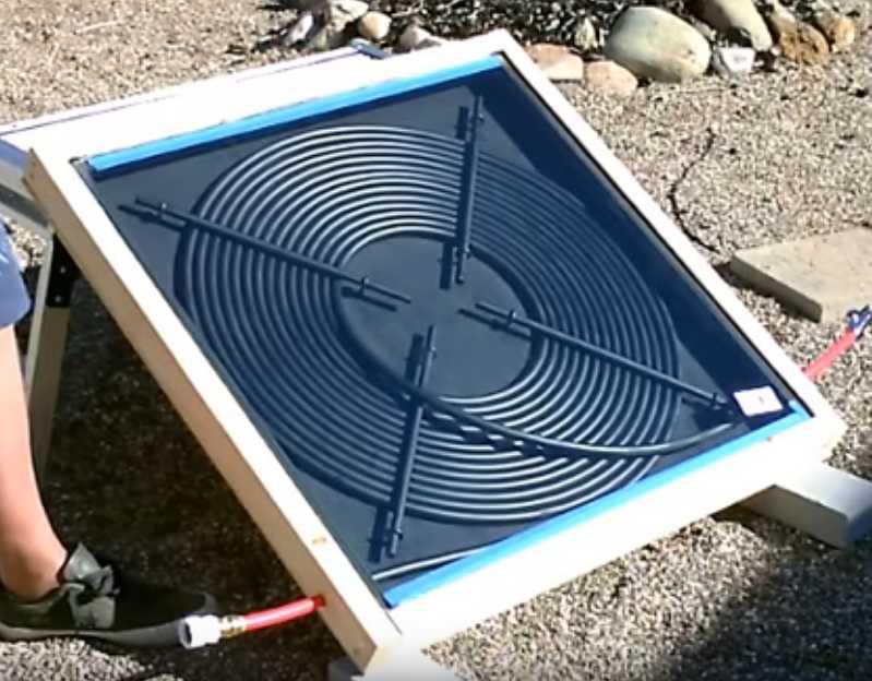 I seem to be
watching a lot of
videos lately. Yet another interesting video suggestion
showed up on youtube, for a homemade hot water solar panel made very
simply, from a coil of plastic "pex" pipe, spray painted black.
Probably not very good for
thermosyphoning, but for any pumped system a coil of pex pipe is rated
both for house pressure and hot water temperatures. Black pipe or tube
solar
panels long have been used for swimming pools, but usually with
polyethylene
pipe that would soften if heated to water tank temperatures and then
burst
under house water pressure.
I seem to be
watching a lot of
videos lately. Yet another interesting video suggestion
showed up on youtube, for a homemade hot water solar panel made very
simply, from a coil of plastic "pex" pipe, spray painted black.
Probably not very good for
thermosyphoning, but for any pumped system a coil of pex pipe is rated
both for house pressure and hot water temperatures. Black pipe or tube
solar
panels long have been used for swimming pools, but usually with
polyethylene
pipe that would soften if heated to water tank temperatures and then
burst
under house water pressure.
If one covered the smallish square panel with lightweight
plexiglass
or polycarbonate, it would be light enough to dismount completely for
winter and store indoors, instead of draining it for winter. If it was
thought to be too small for requirements... just use more pex pipe to
make a bigger coil and panel, or make two of them. Since the pex pipe
covers the entire surface of the panel (well at least a solid circular
area within it), there's no more need for elaborate
soldered-together copper pipe assemblies, fastened to an aluminum heat
transfer backing sheet to get the solar heat to the pipes.
Of course, much of the effort of solar hot water, if it is
to be
plumbed into the home hot water system, is in the preheat water tank
and all the plumbing, and in the pump and controls. But this at least
would greatly simplify making the panel itself!
In fact it seemed so promising that on the 16th I bought a
100' roll
of 1/2" pex pipe and end fittings (to threaded). Will the weather
improve? Will I find time to make it and set it up when it does?
I did in fact look up the part sizes listed at the end of
the video, and put together a box, about 34" square. The one thing that
wasn't listed was the length of the pex pipe. I had assumed it would
have been a 100 foot roll, but when I tried to wind it in to check it
out, I couldn't seem to get it all in - there were at least 4 or 5
meters left over. I wished I had made the box bigger. That said, I
didn't have the corner dowels and eye screws in place to wind it in
nicely as he had done in the video. (I can see those are vital for good
assembly!) But I'm sure enough that I want to make a new box, a little
bigger. With solar collectors, bigger is better. (In fact, another 100
foot roll wouldn't hurt. But perhaps better to make two collectors than
one that's big and awkward.)
---
Later I watched another
video directly comparing solar PV with hot water solar panels. Two or
three electric panels were connected directly to an electric water tank
element. (They were doubtless wired in series to gain voltage for the
120 or 240 volt heating element.) The hot water system had one 32
square foot panel, a circ pump, controls, and a storage tank.
He found that at first the hot water collector did the
best job, but that as the water got hotter, the electric system worked
better and could get and keep the water hotter. The insulated electric
tank with
no circulation had less heat loss. Another finding was that the hot
water collector could heat more water for the size of collector, but
that the larger electric panels were cheaper than the hot water system.
His
recommendation was that if you had space for the PV panels, go with
electric. (I did some tests with direct connected electric in the
article above.)
Definitely the electrical heating method avoids a lot of
costly plumbing. But his collector looked like the sort of typical "old
fashioned" type with copper pipes attached to an aluminum plate. Surely
the pex pipe water collector is much cheaper.
DIY Pex Ring Crimping Tool
An annoyance with pex is that the fittings have to be
crimped on. I don't think hose clamps would do it. (Hmm... I could be
wrong.) It turned out that by far the most expensive component of all
was a crimping tool to put the pex crimp rings on with. At 150$ it was
twice the price of the actual roll of pipe and end two fittings! And
that tool only did 1/2" pex pipe. One that would do both 1/2" and 3/4"
was half again as much, 225$! I didn't think much of that. I went home
and drilled out a small piece of 5/16" steel with what I hoped was
about the right size drill (11/16"), then cut it in half with the angle
grinder/zip disk. (The mini milling-drilling machine, with its table to
clamp down the work and low turning speeds, makes a great drill press
for larger holes!) Since the collector pipe would be portable, I would
use the hydraulic press to push the half circles together to do the
crimp. A later thought was that if I had used a slightly larger piece
of steel, I could have put a bolt through it on each side of the
semicircles, and tightened the bolts to crimp the ring. That way, it
could be used wherever a pipe was being installed, in place of the
costly "real" tool.
Magnetic
Flipping HE Ray Energy?
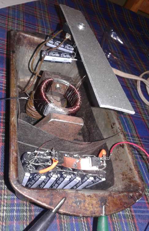 I made up the large non-polarized capacitor I
talked about last month, using fourteen 270 uF, 100 V capacitors and
two diodes. I couldn't find my box of schottky diodes (no doubt they're
hanging out with my horde of missing 5 watt resistors) but I found a
tube of heavy duty surface mount ones. I soldered them to a small piece
of copper. I don't expect them to dissipate much power, so a larger
heatsink shouldn't be necessary.
I made up the large non-polarized capacitor I
talked about last month, using fourteen 270 uF, 100 V capacitors and
two diodes. I couldn't find my box of schottky diodes (no doubt they're
hanging out with my horde of missing 5 watt resistors) but I found a
tube of heavy duty surface mount ones. I soldered them to a small piece
of copper. I don't expect them to dissipate much power, so a larger
heatsink shouldn't be necessary.
But it was so cold out all month I didn't go out to sit in
the unheated garage where my pulse source was to try it out.
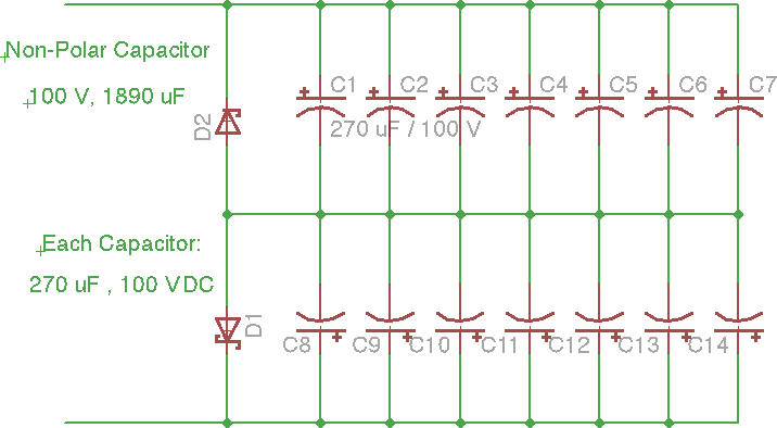
I thought my non-polarized capacitor design was rather clever and I've
seen nothing else like it.
If the voltage is positive, the bottom diode conducts, so the center
leg stays at ground
(disregarding the small schottky forward diode drop) and prevents
reverse charge on the lower capacitors.
The upper ones are charged in parallel with the correct polarity with
their regular voltage rating.
If it's negative, the top diode conducts instead.
The upper capacitors are shorted and prevented from charging backward
The lower ones charge in their proper direction.
(I'll call it a new invention unless shown otherwise! But it's so simple
I'd say the chances are high that it has been done by someone.)
Rechargeable Battery Making
Methyl Hydroxide Electrolyte?
Contaminated Manganese Oxide?
Having learned in January that MnO2 could be "poisoned" by
zinc oxide, by the start of February it occurred to me that the MnO2 I
was using, which I had assumed must be "battery purity", just might
be already contaminated by zinc chloride turned to oxide from those
corroded old dry cells. That might help explain why things
never seemed to work as they should. OTOH, I don't know why dissolved
zinc chloride wouldn't just dilute out of the MnO2/graphite powder
along with the ammonium chloride.
This Month's Take: Electrolyte, +trode, -trode Options
Okay... there seem to be bewildering arrays of
possibilities for making batteries. Let's pick a couple and review
known choices of electrode substances.
We now have methyl hydroxide and potassium hydroxide,
which can be mixed to an optimum pH for electrolyte. The optimum for
most substances appears to be about pH 11.
Then we have ion selective nafion barrier membrane that
only lets protons through. If that really works well, other
possibilities arise.
With these two things, all sorts of electrodes should
work well.
For a positive electrode, one could go for potassium
permanganate or mixed nickel manganates. Potassium permanganate is so
little soluble that as the electrode charges, what little will dissolve
will soon saturate the electrolyte on the "+" side of the barrier. The
rest of it will remain solid, converting from MnO2 to MnO4- at about
+.82 volts at an ideal pH of about 11. Adding the nickel would make
everything more conductive and maintain the potassium balance in the
electrolyte.
Q: In this case, can graphite powder be used for conductivity, or is
the voltage too high and it will bubble oxygen? Idea: Add samarium
hydroxide to raise oxygen overvoltage. If graphite powder doesn't work,
we go back to manganese dioxide to keep it simple. Both ideas can be
tried in the same electrode: first charge it to MnO2. If it works,
oxidize the other electrode (if required), raise the voltage and charge
to MnO4- and see what happens.
For a negative, zinc is still ideal both from remaining
solid (-1.15 V at pH 11) and because even if it doesn't, the nafion
should block zinc ions and thus prevent dendrites from penetrating the
separator and shorting the cell. Theoretical cell voltage would be +.82
- -1.15 = 1.97 volts.
Another possibility is again manganese with previously
found (2013?) hydrogen overvoltage additives that allow it to retain
its high voltage metallic charge, at pH 11 yielding +.82 - -1.35 = 2.17
volts. Again even if it should form the alkaline Mn(OH)3- ion, that
shouldn't pass through the nafion, and should plate back on during
charging.
And I now understand that a zinc current collector at such
a high negative voltage, without overvoltage additives to the metal to
prevent hydrogen bubbling, will turn to fragile zinc hydride as it
bubbles hydrogen during charging. That's why they were disintegrating.
I now also now have lead (Pb) sheet to try out for a current collector,
which might have a sufficient hydrogen overvoltage by itself.
How To?
A key part of this now is to get the nafion membrane in
place so that it fully blocks the interface between the electrodes.
Otherwise dissolved ions can cross to the wrong electrode and slowly or
quickly degrade the cell. Apparently the best way to seal around the
edges is with barium metasilicate. (Does that make a putty of
something?) With or without that, there's little point in trying to
seal a "window screen" in a frame between two electrodes simply
inserted into a container as I have been doing. The frame has to seal
around its outer edges as well as seal the membrane within. Effectively
the frame has to be part of the case, as I was making them some years
back. Except instead of just paper in the frame, we have the nafion
membrane. (Even with the chloride electrolyte, those cells might have
worked fine if I had had nafion separators back then. In fact, even a
standard dry cell should be rechargeable with nafion separators. Does
it really work? Where is everybody with new types of batteries using
them - at least rechargeable Mn-Zn dry cells?)
http://www.TurquoiseEnergy.com
Haida Gwaii, BC Canada