Turquoise Energy Ltd. News #131
covering April
2019 (Posted May 6th 2019)
Lawnhill BC Canada
by Craig Carmichael
www.TurquoiseEnergy.com
= www.ElectricCaik.com
= www.ElectricHubcap.com
Month In Brief
(Project Summaries etc.)
- Greenhouse and Garden - HAT36V-50A Plugs and Sockets - The Last
of the Month - Shingles! - Chemical-Free Iron Filter for Domestic Water
- Solar PV Hot Water Heating - To make the Main Hot Water Tank Grid
Plus
Solar - Turned the hot water tank to 1/4 power - Tugboat Solar Panels
- Ground Effect Craft (R/C Model) - Tesla 3 versus 2019 Nissan Leaf
(video) - Cigarette Lighter: 120/240 Volts AC Power From Any Electric
Car?
In
Passing
(Miscellaneous topics, editorial comments & opinionated rants)
- Hearing Improvement - Shingles - The Weather - ESD
- Project Reports
-
Electric
Transport - Electric Hubcap Motor Systems
* Ground Effect Vehicle (R/C Model): Snail's pace but moving
* Car Charging Mystery Solved: There is no such thing as a 3 KW
charging station (they're 4 KW!)
Other "Green"
Electric Equipment Projects
* "Off Grid" (etc) 36 volt DC Infrastructure
* High Current HAT - 50 Amp Plugs & Sockets
* Today's AC Wire Color Conventions NEED TO BE CHANGED! and
unified with DC conventions
* Solar Water Heating: 36 volt water heater elements
* Hybrid system?
* Regular Hot Water Tank as Combo Solar 'preheat' and Grid Water Heater
* Chemical Free Iron Filters for (eg) Well Water
* Need for voltage controlled operation... & Components for that
* "Custom" Heatsinks for LED Lighting
* DC to DC Down Converters to run 12-24 Volt Equipment From 36 Volts
Electricity Generation
* Another month (April) of solar collector performance logging
* Another palette of solar panels ordered - watts, efficiency are still
creeping up: 315 W.
Electricity Storage -
Turquoise Battery
Project (Mn-Zn, Ni-Zn or Pb-Zn in Methyl
Hydroxide electrolyte)
* Nafion & Osmium Doped Acetaldehyde film Notes
* The Continuing Saga of the NiMH Dry Cells Car Starting Battery (a
little
repair and it still works great! - 7-1/2 years old now)
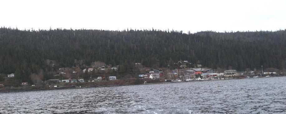
Sometime in April I got a little boat ride from Queen
Charlotte out to check a crab trap. There weren't any crabs, but I got
a couple of pictures of the town looking north from the water - a
little westward, and a little eastward. It's quite a "vertical" town
without extensive level ground anywhere and even steeper hills behind,
and so it's very much spread out east to west along the waterfront.
Greenhouse and Garden
 I
finally got my greenhouse into "operable" shape at the start of the
month. In view of the food scarcity crisis now so obviously
looming for the next few months and a year or two (and even then, only
if there are no more catastrophes in the meantime - hah!), I spent a
lot of
time in April prepping beds in the greenhouse and the garden and then
planting things. (My garden dirt is largely beach sand except for
whatever I manage to fortify it with, so prepping it is extra
important.)
I
finally got my greenhouse into "operable" shape at the start of the
month. In view of the food scarcity crisis now so obviously
looming for the next few months and a year or two (and even then, only
if there are no more catastrophes in the meantime - hah!), I spent a
lot of
time in April prepping beds in the greenhouse and the garden and then
planting things. (My garden dirt is largely beach sand except for
whatever I manage to fortify it with, so prepping it is extra
important.)
I was afraid cold weather and dryness in the greenhouse
had killed my asparagus, but with warmer weather and some watering some
thin stalks started springing up. Nothing like a good eating size, but
at least some were alive. My apricot tree in the garden
looked dead, but it finally started budding by May. The other one, in a
large pot, started flowering early and may actually get fruit, along
with
the fruit trees I had planted north of the house when I first moved. I
had already been eating swiss chard still growing from last year, and
some spinach from the indoor LED garden. But other than potatoes, what
did I really have to make a meal of except some greens? My garlic
planted last fall was up, but all the "winter wheat" was a no-show. I
put in a small patch of barley in March where the quinoa had been last
year. At least that sprouted! I planted corn, but it hadn't done well
last year. I originally was going to plant it in the greenhouse, but
that was probably going overboard. It didn't fare well - I put it
outside too early.
Then I rototilled up a fair patch of grass (10x10 feet?)
and moss clods well outside my regular garden area. It was tough going
and I had to stop and strip the grass out of the tines a few times.
This was the sort of thing I wanted the CNC gardening machine for. But
it might not have handled it anyway.
I was going to plant barley there too, notwithstanding
that the deer might eat it. I couldn't find the barley seeds
(I can misplace anything, anywhere, anytime, better than most anybody
else.) so I dug up some from the small sprouting barley bed to thin
them at the same time. After transplanting to make two rows, it
occurred to me
that corn might be the best thing to plant there. I figured the deer
were unlikely to eat corn, and if I had a good amount, the raccoons
probably wouldn't manage to mutilate too many. (There seem to be far
fewer raccoons here than than in the city in Victoria. In fact I've
never seen any near my house.) So the rest of the bed got corn. A
day later three deer were wandering around the area munching. They'll
probably leave the barley until the grain is ripening, then gobble it
down. Hopefully the corn won't attract them.
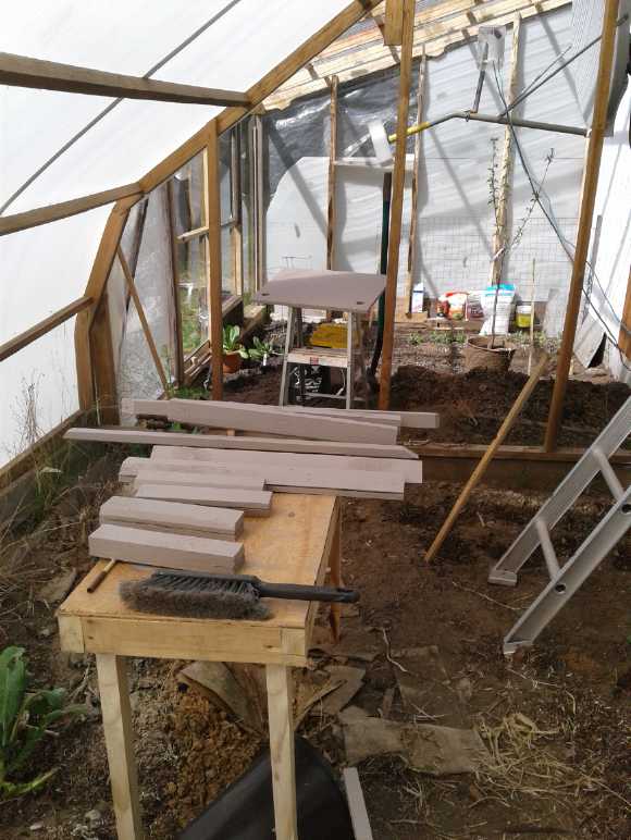
Near the end of the month, I put a table inside the
greenhouse and painted the boards and plywood for the tugboat deck
solar panels. It was warm and the paint dried well instead of taking
days. I managed to avoid stepping in my asparagus, if only barely.
 HAT36V-50A Plugs and
Sockets
HAT36V-50A Plugs and
Sockets
All this gardening was good exercise and may well pay off
later in the summer and fall, but naturally, it
ate heavily into energy project time, which seems to be in shorter and
shorter supply. I managed to design and make 50 amp HAT36V plugs and
sockets, but only by working on them late at night. And after designing
the sockets in 3D printed plastic, for such high currents that will get
very hot if there's a poor connection, I wanted ceramic socket shells.
That means making molds... and fixing the mini-kiln's burned out
element. The first mold didn't go well. I have a couple of possible new
plans. Later I started thinking that lacking the high temperature
plastics used by electrical manufacturers, even the 15 amp sockets and
wall plates should probably be ceramic. This will be a challenge!
The Last of the Month
I woke up on the 21st realizing that virtually 3/4 of the
month was gone with so little to show for it. All I had managed for
energy projects was the HAT36V-50A plugs and sockets. Where does all my
time go? I shifted focus and didn't get much more gardening done.
Shingles!
I felt something on the top of my head, but I couldn't see
anything under my hair. A minor bruise? A couple of days later I
couldn't
understand why it wasn't going away. In fact, had it spread? On the
24th there
were red blotches all over my forehead on the left side. It was
shingles. I
saw the doctor and got some "anti-viral" pills. I rubbed some butter on
the splotches. I'd heard it was helpful or at least soothing. After
that I mostly stuck around home as I was apparently contagious for
chicken pox
- same virus. I went out occasionally for groceries and mail. (Long
version see "In Passing")
Chemical-Free Iron Filter for Domestic Water
But I saw my neighbor (he'd already had chicken pox), and
he mentioned finding out about air injection filters that would get rid
of iron from water without added chemicals. What commonly happens in
many areas (eg, all around this area and in Tlell) is that iron-rich
well water looks clear, but it has dissolved iron II (ferrous) ions in
it. These soon change to insoluble ferric (III) form after they come
out of the tap into air - yellow to red rust - and stain everything.
That's why I've wanted to catch and use rain water for dish washing.
These new(?) filters inject air as the water comes up from
the well pump. So it (mostly) converts to ferric form there, before the
main filter. This is filtered out in the regular sand filter instead of
entering the house water. It seemed "Rainfresh" was a good brand. I
ordered one to pick up in-store at Home Hardware in Masset. (Best
price, too: ~1000 $. Still, there go my savings from not being on
pricey city water any more!)
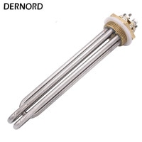
Solar PV Hot Water Heating
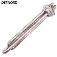
1200 Watt, 36 Volt Hot Water
Tank Heater Elements with
1", 1.25" threads. The multiple elements can be separated.
One is thus 600 or 1200W and the other is 400/800/1200.
 That was a thrilling discovery. It changed the
way I want to do the solar water heater for under the kitchen sink.
I'll just connect the 4 gallon tank to the regular house plumbing and
not to rain water barrels - a great simplification!
That was a thrilling discovery. It changed the
way I want to do the solar water heater for under the kitchen sink.
I'll just connect the 4 gallon tank to the regular house plumbing and
not to rain water barrels - a great simplification!
Making the Main Hot Water Tank Grid Plus Solar
And now I'm starting to have the ambition to disconnect
the lower element in the house hot water tank and replace it with a 36
volt, lower wattage heater. Thus the bottom half of the regular tank
replaces the usual "solar water preheat tank", and is heated by solar.
If that doesn't heat it enough, when hot water is run and the cooler
water moves upward, the top element will ensure there's 1/2 a tank of
hot water. That way that project involves no plumbing except installing
the new heater element.
The problems with the present arrangement are: (1) With
3000(?) watt elements and only 1900 watts max solar power for all
purposes (on a sunny day), most of the water heating is done very
quickly without much time for the solar to help. If I could even find a
low wattage 240 volt element, the grid tie inverters could supply much
more of the slower heat without changing anything else or adding
wiring. (2) If the power goes off for quite a while there'll be no hot
water for the shower. (I don't fancy carrying buckets from the kitchen
sink.)
Setting the hot water tank to 1/4 power
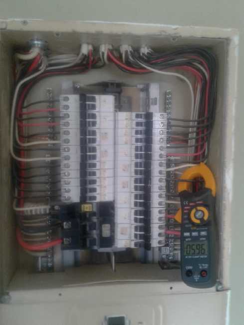 As I was
editing the above paragraph (on May 4th) an
interesting thought occurred to me: In the breaker panel, disconnect
one wire from the double breaker and connect it to neutral. Then the
tank would get only 120 volts instead of 240. Since the only things in
the tanks are the thermostats and the heaters (no electronics, etc),
these would be running well below their maximum ratings. I couldn't
think of much that could go wrong. The elements would run at 1/4 power:
750 watts each instead of 3000. If there's solar power available, it
should easily supply 750 watts instead of 1500 to 2000 of the 3000
coming from the utility. The water will (eventually) get hot
regardless. That seemed so simple I did it that day.
As I was
editing the above paragraph (on May 4th) an
interesting thought occurred to me: In the breaker panel, disconnect
one wire from the double breaker and connect it to neutral. Then the
tank would get only 120 volts instead of 240. Since the only things in
the tanks are the thermostats and the heaters (no electronics, etc),
these would be running well below their maximum ratings. I couldn't
think of much that could go wrong. The elements would run at 1/4 power:
750 watts each instead of 3000. If there's solar power available, it
should easily supply 750 watts instead of 1500 to 2000 of the 3000
coming from the utility. The water will (eventually) get hot
regardless. That seemed so simple I did it that day.
Before I closed the breaker box (what neat wiring), a
clamp-on ampmeter read
about 6.15 amps. 6.15 A * 120 V = 738 W. Well, that certainly was the
simplest of projects! With only one of me living here, I can't see
running out of hot water in spite of the slow recovery it will have.
(I'll find out soon enough if I'm wrong.)
The difference now between this and rewiring the bottom
element with a 36 volts specifically solar circuit is that the solar
circuit would heat the bottom half of the tank only with
available solar power, even if it means leaving it cold all night. But
it would also heat the tank even if the grid was off.
Tugboat Solar Panels
On the 25th and 26th I nibbled away at the triangular
holders for the solar panels for the tugboats, to keep their batteries
up and the bilge pumps working. I should have finished that - at
least - 2 or 3
weeks previously. It was mostly a wood construction and painting
project. That didn't enthuse me much. Installation - wiring to the
charge controller and
battery below - shouldn't take very long.
Ground Effect Craft (R/C Model)
On the 26th I (finally) cut some 2-1/2" wide pieces of
styrene foam for the
bottoms of the hulls of the RC model ground effect vehicle, and on the
27th glued them together. Then I managed to cut and glue some more
pieces at the front and back. The beginnings of a shape are finally
starting to emerge. Next: the spars for the wing, which is also the
"deck" between the two hulls.
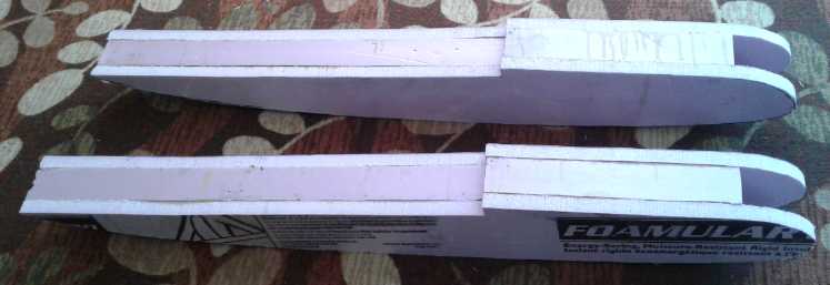 The two hulls for the ground effect vehicle
model take shape,
The two hulls for the ground effect vehicle
model take shape,
from polystyrene foam glued with epoxy resin. - Bottoms
Right way up with fronts filled in.
Tesla 3 versus 2019 Nissan Leaf - video
A father and son team with a garage, decided to compare
two new electric vehicles, Tesla 3 and 2019 Leaf, by taking them on the
same trip 75 miles
each way on the highway including up and down a mountain in
Colorado. The longer range Tesla was charged to show the same number of
miles of "range remaining" as the Leaf. Off they went. "Dragging" from
a stop light
up to the speed limit of 55 MPH, the Tesla pulled way ahead of the
Leaf. (They have scary power!) Both cars left all the gas cars far
behind.
The Tesla seemed to have everything calculated out for
mileage. As they went up the mountain, its "remaining range" indicator
dropped a mile per mile driven. The route was plugged in and it knew
the car would come down again. The Leaf just calculated by power being
used, and the "remaining range" reading ("at the rate you're using
power...") dropped 2 or 3 miles per mile driven. By the top of the
mountain pass, it said only 80 miles left - hardly enough to get back.
Going back down, the Tesla continued to drop mile for mile, but the
Leaf's range estimate was rising (to well over 100) as the power
regeneration refilled the batteries. (As a Leaf owner myself, I was
sure it
would.)
The comparisons when they got back to the shop were
interesting: Both vehicles said 82 miles range left. Both said "20
hours to charge". And both had used 272 watt-hours per mile. (The trip
being high-speed highway driving up to 70 MPH, a lot of the power would
have gone to wind resistance. Slower speeds would have used less power
per mile. An EV-1 with its extra low wind profile would also have used
substantially less.)
Cigarette Lighter: 120/240 Volts AC Power From Any Electric Car?
I have the 36 volt converted Sprint ready to plug into the
house solar system, either to charge it, or as extra stored power if
needed. With a commercial electric car it's trickier. No doubt the car
makers don't want the batteries risked in unknown "off-grid" power
applications, and they don't provide a means to use them that way. But
here's a way
that should work with most any electric car: You can get small power
inverters that plug into the car's lighter socket, to provide 120
volts.
(or I presume 240.) At least for the Nissan Leaf, the car must be
turned ON so that the main batteries will keep the 12 volt battery
charged.
I don't suppose cigarette lighter inverters are very high
watts, so heavy loads are out. And I don't know how
much the car uses for itself sitting there turned on. But it's
something that could presumably run small 120 V items away from mains
power if
needed, and no doubt for a very considerable period of time before
killing the batteries.
In Passing
(Miscellaneous topics, editorial comments & opinionated rants)
Hearing Improvement?
It is generally accepted that hearing deteriorates with
age, and that there's nothing that can be done about it except to avoid
loud noise. Was that really true? On the face of it it seemed to be.
I've never heard anyone say, "Oh, my hearing was pretty poor, but it
got better in my fifties." From past hearing tests I know my own
hearing has deteriorated over the decades. I know from my last hearing
test (I think it was 2012) that I had lost more from making and tuning
recorders (the
flute instrument) between 2004 and 2007. My hearing somewhere around
the 2000-8000 Hz
range - the range for hearing what people are saying - had gone from
one step above to the top of "impaired".
However there are many things that we are told and that we
accept without question, which turn out not to be absolutes. Arthritis
and osteoporosis, "incurable" bugaboos of "old age" until recently and
even now among the many who haven't heard, were discovered to be mostly
caused by boron deficiency, and taking borax cures it like vitamin C
cures scurvy. (There are various rather similar water-with-borax
formulas on line.)
If you don't look for answers, you're not likely to find
them, especially if few others have searched either, so any knowledge
there is is not being shared. I searched on something like "hearing
improvement" on youtube. That brought up an
odd video with synthesized voice that said to put drops of garlic juice
mixed with oil in your ears. It was pretty vague on details, but
somehow I got a sense that they might be onto something. How might one
more directly affect the ears than by putting something in them? Was it
like a vitamin? Did the oil give the little vibrating hairs a rest? Did
it clean the wax out? I decided
to try it out in my left ear, which if anything seemed to be poorest.
The video said nothing about time or applications. One
application certainly did nothing. Disappointing
perhaps, but to be expected. If it worked like that, everyone
would be raving about it. Like arthritis, one doesn't (normally) get
bad hearing ovenight, so why would one expect to cure it overnight?
After crushing garlic and mixing the juice with oil
a couple of times, I dispensed with the garlic. For a while I used
peanut oil, then I switched to olive oil. I don't know if one oil is
better than another. The peanut oil seemed to drain out a bit more
readily.
You have to find just the right place at the back at the
top where the dropper can be put in farther (just a little
farther, no more!), and the oil goes right into the ear. I just squeeze
the dropper slowly until it sounds like I've gone underwater. It's just
a couple of drops. Then sometimes I roll up a bit of tissue and put it
in my ear, and often I get some oil on it. Then I just let it drain
out. If I put my little finger into my ear, even hours later, it often
comes out oily. I've now been trying it for probably 3 or 4 months,
usually once or twice a day but missing sometimes. (Rats, I've kept no
record of when I started.)
In recent weeks I started noticing frogs croaking. They
have a high pitched sort of "chirping" to their sound and they go on
and on (until they all suddenly stop at once for a while, for no
apparent reason), so it makes a good test. First I noticed it lying in
bed with my left ear up. Was I hearing this faint sound from outside
more than usual? I turned over and I had the impression that the higher
parts of the sound - where the tests had said my hearing was poor -
were more subdued with my right ear. I continued with the oil and by
the end of April I think I can pretty safely say that if I plug
my right ear and listen with the left, the sound has more treble
"presence" than through my right ear alone. I have the impression I
hear more frogs, some from farther away. Listening to a couple of other
things, power pole transformer hum seemed no better in my left ear, but
some heavy machinery in the distance was definitely clearer.
I probably lost my several hearing test result cards from
the late 1980s and early 1990s and the one from 2012 when I moved to
Haida Gwaii. At least, I've looked in the drawer where I once kept them
(so long ago) and have no idea where they went. (I wonder if they're
still on record at Island Acoustics?) But I have a fair memory of what
the charts looked like. They weren't very good, and the one from 2012
was worse as mentioned. If a test would show the left ear improved over
the previous test, and over the right ear, that would be definitive
proof. As it is, it's what and how I think I hear - subjective
evaluation that's says "I seem to hear better" and I think
I know roughly what a chart would look like, but it can't be quantified
in decibels and I'm not absolutely sure it's any better at all.
One disappointment of note: So far I have not noticed any
change to my tinnitus.
I called the clinic. If they do hearing testing it would
be silly to not check it out. An audiologist periodically comes to the
Skidegate Medical Clinic. He had just been there. I can book an
appointment for next time, in August. Well, that gives over three
months to apply more drops in just my left ear, to have an even more
certain idea that it's improving.
Shingles
The virus that causes Chicken Pox usually hits when one is
young. (It is in fact more serious if it strikes when one is older -
notably it can cause sterility.) Once you've had it, you're immune. You
don't get it again. But they never completely die off. Apparently they
eek out a living in the skin or away from the body's main immune
defenses. And they can cause "Shingles" later in life - nasty red
splotches that hurt like heck. Variously, they tingle, feel like you've
been stung by a wasp or have been hit with something. And in fact the
skin all around seems to all be sensitive to an extent even where
there's no splotch. They somehow follow a nerve, and affect the skin
only where that nerve surfaces. This is good, because I'm sure it would
acutely serious to fatal if they spread everywhere. One area is plenty
bad enough. I've heard it can stick around for months. And if it gets
in your eye, it can blind you.
None of this was on my radar screen. One day my head hurt
in a couple of places, but I couldn't see anything under my hair and I
payed it little attention. I had bumped my head a couple of days before
- lightly I thought. Must be a bruise? taking so long to start hurting?
This went on a couple more days and I started to wonder. And had it
spread? The next morning there were red splotches all over the left
side of my forehead.
I still had no idea what it was. I went to the pharmacy
and the pharmacist thought it looked like shingles and that I should
try to see a doctor. Luckily the nurse decided I'd better see the
doctor on duty before she went home after she finished with two or
three emergency patients. So I waited. The doctor was very concerned
because it was so close to my eye, and did a retinal exam. She
prescribed me "anti-viral" pills, which I had never heard of before.
These apparently are specific to various viruses (and yes, there seem
to be some for flu, but dubiously effective). They stop the virus from
multiplying rather than killing it outright. Herpes and shingles have a
certain enzyme targeted by the pills. If I had taken them sooner the
whole thing might have been much milder. I got back to the pharmacy
just in time to get the prescription before they closed.
Somewhere I had heard of putting butter on the splotches.
I started doing so. I thought it might merely alleviate the pain. But
I'm starting to think there's more to it. The virus can't give you
Chicken Pox twice because your body has built up an immunity. So to
cause shingles the virus is recurring at some weak point in the body's
defenses, which somehow involves the skin and a nerve. On the outside,
the virus has access to the air, away from the body's defenses. By
greasing the skin, that access is blocked. Some sorts of skin nasties -
mites?, scabies?, bacteria?, fungus?... and shingles/chicken pox virus,
might just be suffocated or "drowned" by or in butter. What besides
butter might work? Oils and margarine would probably soak into the skin
and have no lasting effect. (Who would want to use automotive grease?)
Maybe lard, or vaseline? Butter is probably pretty neutral and mild,
and it washes off easily with soap or shampoo. Perhaps it's unique?
Later someone told me there was a special cream for shingles, Capiscum.
(Why wasn't I told about it at the clinic or pharmacy?) From the
description it sounded a bit harsh.
The rubbing to apply it hurts, but is probably helpful in
itself. (Brushing or combing my hair, or even anything touching the
left side of my head, is excruciatingly painful. Improving by May 6th.)
The doctor had me come in the next morning for another
retinal exam, which seemed okay - somehow better than the previous
evening. She said something about some eye drops, Polysporin with
antibiotic. But the lowest splotch was above my eyebrow. I didn't think
that was close enough to worry. Over the weekend a new red splotch and
some swelling appeared right over my eyelid. On Monday morning I drove
into town and got the Polysporin and immediately went into the washroom
and dropped in the drops. I should have bought it in the first place,
just in case! No doubt I should have been taking them regardless of
where the shingles was. Anyway, nothing seems to have happened. I went
into the post office to get my mail, and a lady waiting there for
something told me a horror story of someone who had got it in their eye.
Two days later on May 1st (after a week) I ran out of the
antiviral pills, and the shingles, while somewhat improved, definitely
wasn't gone. (and it looked like so many pills... but the dose was two
at a time, three times a day, so they disappeared fast.) Being pretty
sure they were helping, maybe a lot, I went back and got the
prescription renewed. I know at least with antibiotics you shouldn't
quit taking them in the middle, and I could see the virus coming back
with a vengeance with no more antivirals, to last for the reputed
months of shingles - with the ever present threat of getting some in
your eye(s), perhaps by rubbing or scratching your affected skin and
then rubbing your eye.
As of May 2nd, the red splotches were shrinking. A couple
of people asked why I hadn't had shingles vaccine. I had never given it
a thought. One person was currently one needle into a two needle
immunization. She didn't know if she had had Chicken Pox! Can they
really give you shingles vaccine safely without you first having had
that? But apparently the shingles vaccine is only good for a limited
time anyway, albeit for some years. And there's no point having it for
a year or so after having shingles.
The Weather
The weather is everywhere - globally - heading into
extremes. Although poorly reported on the mainstream media except
locally, weather stories saying "record breaking" and "unprecedented"
are all around us. The more than severe flooding in the central USA,
Queensland (Australia) and Mozambique was repeated in Iran,
Argentina, South Africa, and Ontario (Canada). Elsewhere there are
droughts, snow, record lows, record
highs, hurricanes, tornados and hail storms with pellets so huge they
kill both small and large animals.
IMHO the major cause of all this is geoengineering and
especially the "chem spraying" - the huge project making of cloud cover
at extra high altitudes all over the world. In most any outdoor photo
anywhere nowadays one can see spreading jet trails in the sky in
the background. The climate will probably just continue to get worse
until this absurdly unsound attempt to reflect sunlight away "to
reduce global warming" is ended.
Then we note mass die-offs of life daily or even more than
one daily around the globe. And it's not just fish, sea birds and
dolphins now. Insects are under threat with the monarch butterfly in
danger. "Colony collapse disorder" is happening to honeybees and
biologists have become worried that the entire genus "bumblebees" may
become extinct. Nicotinoid insecticides appear to be largely to blame.
Then, the numbers and variety of amphibians has shrunk to half globally
and
is still shrinking rapidly. They are being called "The canary in the
coal mine." I don't even remember the horrific estimate of the number
of species of life going extinct.
Who would have suspected that life on Earth as a whole
might become so endangered without a nuclear holocaust?
Here on Haida Gwaii pretty normal rains come down ("drier
than usual" is actually more pleasant here as long as it doesn't extend
to drought and forest fire). The bumblebees buzz in the dandelions
and in almost a swarm in my big flowering currant bush, and the frogs
croak up a storm all
evening in a nearby swamp. Chemtrails only dull some otherwise sunny
days. The location out
in the Pacific ocean is probably favorable. Then there's the fact that
there is no "big agriculture" with pesticide and herbicide spraying
here, and the small population is not making every possible speck of
land ideal for humans or crops at the expense of everything else. And
the
Haida having taken much local control of the fisheries, the sea is
probably better managed here than most places. They've closed even some
of their own favorite fishing spots to make safe places for marine life
to reproduce and thrive. Some of the global die-offs of starving marine
creatures and sea birds probably indicate that the whole ocean is being
seriously fished out,
but fishing is good here.
ESD
(Eccentric Silliness Department)
Philosophy: There's no point getting up on a ladder and cleaning your
gutters if it isn't pouring rain.
Someone said "preppers" are keeping the economy going. The economy is
so bad they're the only ones in the lower 75(?)% of the population
still buying things they don't immediately need.
Failed company slogan (it came back to bite them): "At Eclar fresh
produce, we put the asp in asparagus"
Instractions: instructions that distract the mind from actually getting
the job done. (eg: wading through the first five pages of safety
warnings.)
Neighbot: the robot horse next door. (Ooh those typos!)
Prepeat: Hmm, this one-word oxymoron just seems to defy definition. The
time just before hearing the same story over again?
"in depth reports" for
each project are below. I hope they may be useful to anyone who wants
to get into a similar project, to glean ideas for how something
might be done, as well as things that might have been tried or thought
of... and even of how not to do something - why it didn't
work or proved impractical. Sometimes they set out inventive thoughts
almost as they occur - and are the actual organization and elaboration
in writing of those thoughts. They are thus partly a diary and are not
extensively proof-read for literary perfection and consistency before
publication. I hope they add to the body of wisdom for other
researchers and developers to help them find more productive paths and
avoid potential pitfalls and dead ends.
Ground Effect
Vehicle (R/C Model)
A catamaran doesn't look
much like an aircraft. Yet one can find videos of radio controlled
(R/C) models of this sort flying - mostly just above the ground, but
also up into the sky. For real life transportation, I don't think we
even want something capable of flying up into the sky. I'm hoping this
won't even need an elevator, although I'm putting one on the R/C
prototype. Ideally it will just be that if the throttle is pushed far
enough forward, the vehicle will rise and float over top of the water
instead of in it, at very high speed because of the reduced friction.
(I would be unhappy with less than highway speeds, with very low energy
consumption.) "Landing" is just lowering the throttle until it settles
back down. No aircraft pilot skills should be required. (And we
certainly don't want to attract the attention of federal aircraft
regulatory agencies!)
I finally got
back to this
near the end of the month. On the 27th I mixed epoxy and glued on the
bottoms of the hulls.
The "step" hull is ubiquitous in water take-off craft. As
speed increases the whole rear end lifts out of the water and more and
more the craft is planing just on the area in front of the step, with
less and less water friction until take-off. Then, flat bottom hulls
pick up speed and plane on the water considerably more easily than "V"
hulls. It's just my own supposition that this will make for easier
take-offs with less power.
In an aircraft the bottom profile behind the step gets
higher (farther from the water) toward the rear so it can "nose up"
without them hitting the water. In this design, the rear of the wing
almost touches the water too, which will lift the rear. In fact, the
back of the wing will surely be immersed before starting the takeoff
run. Here we don't want it to fly up into the sky, only to get it
"floating" above the water's surface.
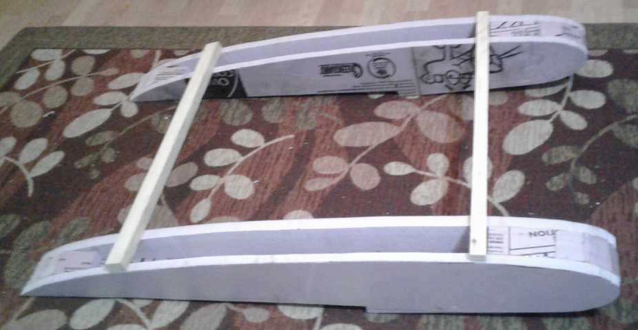
 Piecing the Pieces
Epoxy curing in the warm
greenhouse
 The following
night I cut a bunch of little
pieces to do the curves around the fronts and along the tops to where
the
front of the wing starts. And a couple of pieces to fill in the backs
of the hulls to the point where
the wing becomes the elevator. This was all made with styrene foam. On
the 29th I glued the pieces to the hulls.
The following
night I cut a bunch of little
pieces to do the curves around the fronts and along the tops to where
the
front of the wing starts. And a couple of pieces to fill in the backs
of the hulls to the point where
the wing becomes the elevator. This was all made with styrene foam. On
the 29th I glued the pieces to the hulls.
The hulls are
to be covered with a thin sheet of epoxied PP cloth. (This needs to be
done if only to cover up that smug "pink panther" picture printed on
the foam.)
Epoxy Techniques: I mixed the epoxy and painted it on in the rather
cold shop. (13°C?) One can be sure the epoxy did very little
setting in there. Then I put the pieces out in the warm greenhouse with
the sun
on it (yay, there's sun!) to set in a reasonable length of time.
(25°C?) For the bottoms I left them overnight with weights on them.
I wanted it all securely hardened into place since the sides wanted to
warp into curves and would probably peel off with the slightest
opportunity.
The unused epoxy and the brush go in the
freezer between sessions. At -18°C they only last a day or two. In
my present freezer at -22° to -25, they last several days.
The spars for the wing, which also hold the two hulls
together, would be spruce. I didn't get started on that part. I needed
to figure out how tall (wide) each spar should be to make the right
wing profile as well as how many spars to put on. And it must be
remembered that unlike a deck, the wing will be lifting the whole
vehicle, not just sitting pressing down on the hulls. That will require
different reinforcement - especially in the full size vehicle.
On May 3rd I measured the wing thickness off the diagram,
which was based on printing out the profile sent to me by John Ryland [
RylandResearch.co.uk ], and came up with a table:
Inches from
Front - wing thickness/spar width
00" - 0
0.5"- 0.84"
01" - 1.29"
06" - 1.56"
12" - 1.65"
19" - 1.80"
25" - 1.70"
32" - 1.35"
Behind 32" (to 38") is the back of the wing and the start
of the elevator. I was surprised by how wide the spars were to be. I
guess the key to lightness is to keep them thin front to back.
An Electric Amphibious
Aircraft - New Design (Let's see... if I put wheels on mine... you'd
still need to use a boat launch ramp
because you couldn't get over the fence to an airport. But maybe it
could be its own trailer?)
Is it even conceivable I could make anything that looks that slick? I
should probably at least try for that skin smoothness.
 There are some
electric airplanes being made now including amphibious ones. One of
them is to be tried on the Victoria-Vancouver run. I salute that
effort! The whine and smell of the float planes all day was just a
small one of several things that were making life in Victoria less
pleasant and helped spur my moving to Haida Gwaii.
There are some
electric airplanes being made now including amphibious ones. One of
them is to be tried on the Victoria-Vancouver run. I salute that
effort! The whine and smell of the float planes all day was just a
small one of several things that were making life in Victoria less
pleasant and helped spur my moving to Haida Gwaii.
(Warning: Digression! Much worse was
Telus
putting an equipment box with 24/7 ever-whining fans on my boulevard
right
outside my formerly quiet back yard in 2009. Did I have to live with
that for the rest of my life? And BTW they tried to rip me off - kept
billing me monthly and pretended not to know - when I switched to Shaw.
Even tho they cut the phone line off from their office. I found
out they were doing that to everyone, and of course most people
wouldn't know how to test the line and so couldn't dispute it with
them. People should have gone to jail for that scam and
betrayal of public trust (especially the CEO, I'm sure - these things
aren't authorized from the bottom!), but I'd be most surprised to hear
anyone did. But I digress.)
I'm becoming more keen on making the full size manned
vehicle electric. If it couldn't fly to Prince Rupert, there are still
a number of very
interesting local trips it could take. Seen flying around and videoed
it should be at least a demo of the potential and hence an inspiration.
Then again, if someone
can do a commercial electric float plane on the Victoria-Vancouver
route, or make an amphibious aircraft that can fly for an hour, and if
the ground effect vehicle really uses 1/4 or 1/3 of the energy of an
aircraft, perhaps the potential for a couple of hours flight to reach
the continent is
there even with present day batteries? Might it really float on the air
so effortlessly just above the waves?
Car Charging
Mystery Solved: There is no such thing as a 3 KW charging station -
They're 4 KW
After a trip the car dash would indicate numbers along the lines of:
"Time to Charge / 6 KW - 3:00 hrs / 3 KW - 3:30 / 120 Volts - 9:30".
Why should 1500 watts take more than twice as long to charge as 3000?
And why was there so little difference between 3000 and 6000 until the
car battery was very low?
I had assumed from the times shown that at 120 volts the
charge
was only at around 1000 watts (eg, the Miles truck is 1100 W). But when
I put a power meter on it, I found it was drawing the full 1500 watts
allowed on a regular 120 volt circuit. That's fully half as much as
3000 watts. Counting tapering off near the end of the charge, it should
be less than double.
Finally I looked online and found a table of charging
times for various vehicles with various chargers. There is no 3 KW
charger! The lowest one shown other than 120 volts, was "3800 watts"!
That explained the discrepancy. The used charger I bought had been sold
to me as "3 KW", and "3 KW" was what it said on the dash of the car.
Looking at some fine print on the side of the "3 KW" charger, it didn't
say anything about power, but it said it drew 16 amps continuous. 16 A
* 240 V = 3840 W. That's virtually 4 KW, not 3!
Based on the erroneous "3 KW" figure being bandied about
everywhere and nowhere contradicted, I had installed it with #14 wire
and a double 15 amp circuit breaker. It should have had #12 wire and a
double 20 amp breaker. I suppose the #14 wire gets pretty hot, and it's
a small wonder the breaker doesn't keep tripping.
I am appalled that this false figure is being perpetuated.
Here it has needlessly caused a reliability and safety issue, and
really I should rewire the whole thing. (Lucky I didn't refinish the
wall I had to rip apart to put it in.) How many other DIYers have just
accepted "3 KW" and done undersize wiring?
A new mystery now appears: The car takes more
kilowatt-hours to charge than it says it used. It might say after a
trip, for example, that the average was "7.2 Km/KWH". So if I
drove 55 Km, the car should have used 55/7.2=7.6 KWH. According to
that, the car should take a little over 5 hours to charge. Instead it
says "9 hours to charge" at 1500 watts. That's 13.5 KWH. Charging seems
to taper off in the last hour, so call it 13 KWH. Another reading says
"52% charge remaining" - from 24 KWH batteries, that indicates 11.5 KWH
used. Either way that's almost double what it says it used in the
"energy economy" section. I don't know if it takes 9 hours to charge,
but it certainly takes more than 5.
Other
"Green"
Electric
Equipment
Projects
36 V DC "Off
Grid" Infrastructure
Looking on the "Dernord" pages for low voltage water
heating elements I noticed that there was a "Number of Orders" below
each model. I tallied up the orders for all models of DC heater
elements on page 1 and found:
* 12V (445 orders) is incomparably the most common
* 24V (89) is next most common
* 36V (34) is the least common but by no means rare
* 48V (59) is third most common
There were no elements for any other specified voltages below 120 volts.
I'll take a guess that those running 36 volt systems are
those who are like me more prudent (or less sporting?) who wanted
higher efficiency but didn't want to go to the somewhat dangerous 48
volt level. Or perhaps they've noticed that you can readily buy cheap
DC to DC down converters for up to 40 volts input for running 12-24
volt equipment, but not for 48 volts.
Manual Method of Switching from "Regular" to "Grid Down" Operation:
Automatic versus Manual?
The day after posting TE News #130 with the idea for
powering the house or some extension cords using a pure sine wave
inverter to activate the grid tie inverters, I found a video by "altE"
("alternative energy store") called Adding Batteries to Grid Tied
Solar
in which that very topic is discussed.
Two different methods are outlined. Both require that you
make an "essential loads panel": a separate breaker box for freezer,
well pump, furnace fan and essential lights and plugs. When the grid is
down, only this panel will be powered and the main breaker box will be
dead.
For new construction this isn't a really big deal.
Installing wiring in open wall studs before the wall surfaces are put
on is pretty simple. But retrofitting a new, separate AC breaker panel
with diverse new outlets and circuits
in a typical existing house would be a prohibitive amount
of work.
The "AC Coupling" is about the equivalent of my idea last
month
of a power bar plugged into the pure sine wave inverter and having
extension cords to the grid tie inverters and to the appliances except
that it's all prewired permanently in advance. The driving inverter
apparently has to be of somewhat bigger capacity than the grid tie
inverter(s) it activates.
The "DC coupling" type evidently requires
there to be one big grid tie inverter instead of several "micro
inverters" like I have, and they talked about having several solar
panels in series making for lethal voltages, so I didn't pay it much
attention.
Having panels in parallel is valuable in many
installations of
which mine is typical: When some panels are in the shade, the other
panels still produce full output. If the panels are in series, having
one in shade kills the whole series string.
Later I found "smart" "Hybrid Inverters", which I confess
hadn't crossed my radar screen before. Here is how the "automatic"
works in installations where everything works "optimally" without any
manual intervention in any situation: sun or no sun, grid on or grid
off, all switched automatically. The most versatile units can draw
power either
directly from the solar panels or from the batteries, and also from the
utility grid as necessary. If the grid is down, solar is
off or insufficient, and the batteries are low, they will even start up
an automatic fossil fuel generator. They operate both as grid tie
inverters and off-grid inverters, switching their output from the main
line to the "essential loads" panel (disconnecting it from the rest) if
the power goes off.
The chief drawback as I see it is that this complexity costs a lot.
Solar done with all the official permits for grid tie and such
equipment, installed by those in the business, costs a lot more than
"basic solar" done DIY. To have a contractor come in one might start at
15000 $. Still, one can DIY and still follow approved
guidelines with lower cost hybrid inverters such as Conext MPPT 60 150
(still over 500$).
That is probably worth it in a "serious" new installation with 20 or 30
panels.
You can start solar for a very low price. A small panel
for 12 volts, a PWM charge controller and a 12 volt lead-acid
"RV/Marine" battery can be under 200 $ and will at least run an LED
light and charge a cell phone.
Moving up a step, four solar panels or so, a cheap charge
controller and a set of golf cart batteries might be under 2500 $ and
would do the essentials if the grid went down.
For myself I guess I've never taken doing a "proper"
installation too seriously. It grew very much piecemeal. I started by
putting up four solar panels for emergencies, then I thought I might as
well have a cheap grid tie so their output wasn't going to waste. Then
I put in a convenient little "boost" charge controller for 36 volts and
hooked up my collections of NiMH batteries. And somehow it grew to 10
panels on two roofs. Then I started adding 36 volt infrastructure,
which I prefer to 120 volts AC but which of course all needs wiring,
and wiring in existing buildings is generally a pain in the butt. (I
think even if I get HE ray electricity going, I would prefer to run
house wiring, if it will still exist, as 36 volts.)
With more or less two separate small solar installations
and no "essential loads" panel wired in, I'm planning only a "manual
intervention method" switching of power with inverters and extension
cords to keep some lights, the fridge, freezer and well pump going if
the utility grid is down. But further DC capacity is planned. The more
things that can be run
off the 36 volts, the better. Water heating is usually a good use
because it's second only to heating for electricity use, and the
solar-heated hot
water will lower the electricity bill. Let's outline my setup - some
features existing, some projected for completion in the coming months:
- 10 solar panels on two roofs.
- Six solar panels, 1800 watts go to two simple grid tie 1000 watt
"micro"-inverters.
- Four solar panels, 1000 watts go to a 36 volt, 10 amp "boost" charge
controller (and-or a grid tie inverter)
- A 36 volt, 60 amp "buck" charge controller is ready to switch in for
"grid down". (I can't find any higher power "boost" converters.)
- around 6 KWH of NiMH batteries.
- The Sprint car is also 36 volts and
can add over 11 KWH of additional storage by connecting it instead of
the other batteries.
- A 36 volt breaker box with "Blue Sea Systems" type DC breakers, and
with a voltage, current, power and power consumption meter.
- a few HAT36V wall receptacles in the house for lights (etc)
- a HAT36V-50A 50 amp one for the small kitchen hot water tank.
(drawing 11, 22 or 33 amps depending how many heat elements I hook up.)
I'll be running a very few (three or four?) "HAT36V" DC
outlets around the house from the DC/solar breaker panel in the garage,
and these could substitute - with some manual intervention. I would
unplug the small hot water tank [with the 36 volt DC element - see
detailed report] and plug in an inverter into the "HAT36V" 50 amp DC
outlet in the kitchen, and plug the fridge and freezer into this
inverter as required to keep them cold when the mains power was off.
Extension cords as required. (It just better not happen while I'm away!)
If it looks like a long outage, I have to disconnect the
MPT7210A 10 amp charge controller and connect the PowMr 60 amp one,
putting the two pairs of 250 watt panels in series. (I'll probably put
in a big DPDT switch for making this changeover. It would leave the
grid tie and MPT7210A connected to the two grounded, lower voltage
panels. These could be turned off or left on. If the MPT7210A was set
to charge at a slightly lower voltage than the PowMr)
I'll already be running LED lights from the DC outlets
(mostly 12 volt ones with the little DC to DC down converters), so that
takes care of 'emergency' lighting.
It's certainly not a perfect system. One minor aggravation
is high-power appliances. If I'm making 1500 watts and turn on the 6000
watt clothes dryer, I can't
spread the load out. It's "make the 1500 and buy the rest 4500
from the grid", and then go back to giving power to the grid free after
the dryer shuts off. Charging the car is normally at 3800 watts too,
but I
can plug in the 120 volt, 1500 watt adapter and spread the time out...
except that I'm usually getting home toward the end of the day.
Switching the water heater to 120 V / 750 W [see "April in Brief"]
should help spread the load and use the solar -- if I run hot water
during the day instead of at night. Anyway
even with 10 solar panels I'm not making enough power for my own daily
needs.
If the grid really goes down for a long time, hopefully
the trailer's extension cord can be plugged into the off-grid inverter
and that will bring its "grid tie" inverter to life so I can make use
of the trailer's output. Otherwise, it may use another PowMr charge
controller and 36 volts of 40 amp-hour lithium batteries that I have
for a separate trailer system.
That's at least enough to keep the lights on at night (if the trailer
is being
used).
High Current HAT - 50 Amp Plugs & Sockets
I thought it would be good to have the high-amperage HAT
connectors I had conceived of. If I ran a line across the house it
could go to the 36 volt water heater in the kitchen, or that could be
unplugged and the 36 volt to 120 volt inverter could be plugged in
indoors (warm and dry) to run the freezer and or fridge in a power
outage. The freezer is about 100 watts, and the fridge is about 140.
Theoreticly that's only 3 or 4 amps at 36 volts, but those compressor
motors draw a nasty surge current as they start. They may choke a 1500
watt inverter (= 42 amps at 36 volts) and not start up. My 1800
watt/2500 volt-amp pure sine wave inverter worked in the previous power
failure. It's probably just big enough.
What should I base the size and shape of a high current
HAT connector on? The vital part is the pins/blades. Everything else
depends on them. Of course I would use the same essential shape. A
target current would be a handy spec, too. 50 amps at 36 volts is 1800
watts - the same as 15 amps at 120 volts. That seemed like a good
starting target.
For comparison and contrast with what others have done:
Blades in a NEMA 30 amp 120/240 V [clothes dryer] plug measured about:
2.4 x 12.7 x ~30 mm, which is also (and probably specified
as) .10" x .50" x ~1.25". Cross section would be 30 sq.mm.
Pins for 30 amp Anderson APP connectors changed shape along their
length, but were pretty tiny compared to the NEMA plug.
Pins for 70 amp APP connectors had a cross section of about: 2.1 x 7.1
mm, cross section 14.91 sq.mm. (Call it 15.)
The NEMA plug had big blades and was intended for just 30 amps. But the
common 120 volt, 15 amp blades are 1/2 the width and (again just via
measuring one) not much more than 1/2 the thickness, so 1/4 the cross
section for 1/2 as much current. As with the exactly .50" width spec,
everything suggested that the NEMA blade size was arbitrary and
substantially larger than actual current flow requirements. This belief
was further supported by the 70 amp APP plug pin having just 1/2 the
cross section of the 30 amp NEMA blades. 15 sq.mm would have a little
bigger cross section than #6 AWG wire. #6 AWG wire is rated for 55, 65
or 75 amps depending on the wire temperature permitted: to 60, 75 or 90
°C. (quite hot to really hot!) These ratings consider the heating
of a long length of insulated wire under heavy load. Plug and socket
pins are short and the wire itself (if thick enough) carries heat away
from the plug pins. (Of course, there's no help for the heat made by a
badly connecting plug and socket in any event.)
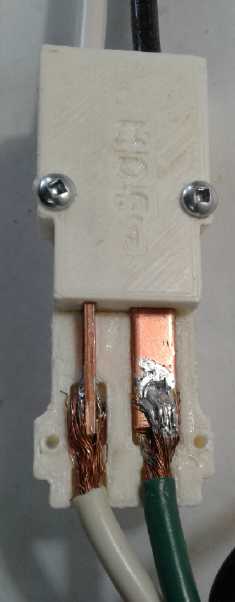
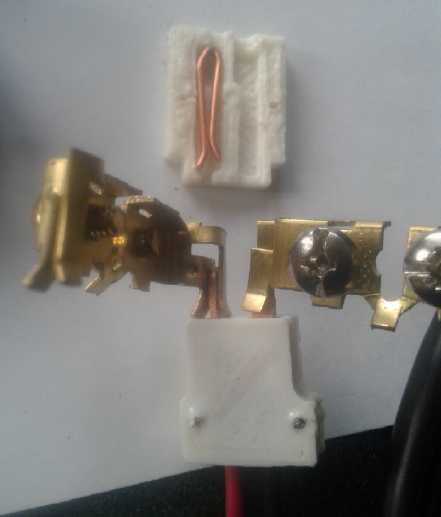 A 120 VAC, 15 amp wall receptacle opened up.
The grips for the plug pins are about the same size and grip as the
HAT36V "hatpin" grips,
and in fact they hold the HAT blades quite well.
(Oops, the 120 V plug with its big blades for comparison is just off to
the
right.)
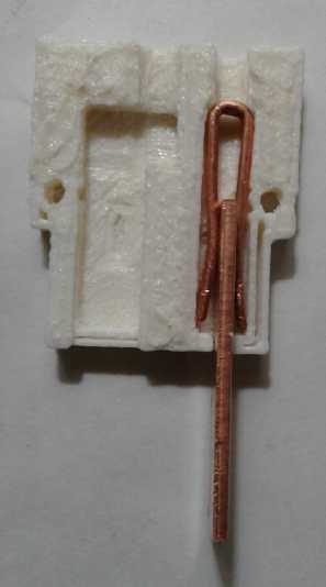
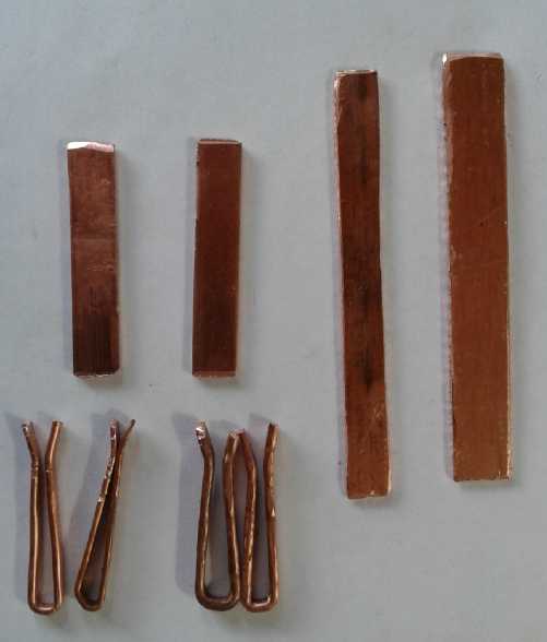 I cut a piece
of 1.65 mm copper sheet/plate, 10 mm wide.
That seemed kind of wide. If I made my HAT blades 8 mm wide by 2 mm
thick (nominal), they would be 16 sq.mm. That should be sufficient for
over a 50 amp circuit. (Or should I call it "60 amps" just so it'll be
known as "2000 watts capacity".) I decided they should be about 20 mm
long. Again, just long enough compared to the width for a good grip
when plugged in. Just by eyeball after making a few socket shells, 12
mm seemed like a good spacing between pin centers. So those dimensions
become the specs.
I cut a piece
of 1.65 mm copper sheet/plate, 10 mm wide.
That seemed kind of wide. If I made my HAT blades 8 mm wide by 2 mm
thick (nominal), they would be 16 sq.mm. That should be sufficient for
over a 50 amp circuit. (Or should I call it "60 amps" just so it'll be
known as "2000 watts capacity".) I decided they should be about 20 mm
long. Again, just long enough compared to the width for a good grip
when plugged in. Just by eyeball after making a few socket shells, 12
mm seemed like a good spacing between pin centers. So those dimensions
become the specs.
36 volt, 50 amp HAT plug blade size specification:
Thickness: 2.0 mm +/-.25 mm (1.75 to 2.25 mm)
Width: 8.0 mm +/- .5 mm (7.5 to 8.5 mm)
Length: 20 mm +/- 2 mm (18 to 22 mm)
Blade center spacing: 12 mm (tolerance unspecified)
These pins are a little bigger in all dimensions than NEMA
120 volt, 15 amp plug pins. I don't think they should be any smaller. I
came up with 12.0 mm blade spacing after making some shells and finding
that 15 mm seemed to leave wasted space. 15 was what I had originally
thought just by setting the pins beside each other and setting them
what seemed a reasonable distance apart.
Obviously 2 mm x 8 mm copper blades aren't going to be
made on the spot just by flattening a wire with a hammer. But the pins
need to be large for high current. 2 mm sheet copper or 2x8 mm strip is
going to have to be obtained for the purpose.
Having that spec, how long would the actual pin be cut? I
decided to make it 40 mm. So 20 mm would stick out to connect, and 20
mm would be inside the shell to hold it in place and connect to. It
seems to me that 8 x 2 mm is wide and fat enough to put a machine screw
through to make a solderless connection. (But I didn't try it.) I cut a
couple of pins to that length. That was it for the 13th.
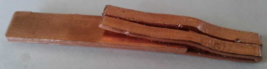
 On the 15th I
I cut some flattened wire
"hairpins" for
sockets, 65 mm long. Instead of one, there would be two for each 8 mm
wide plug blade, 4 mm wide or less. Two springs would make a better
connection than a single point. I made two from #9 AWG wire. This
turned out to be quite hard to bend around. The other two were #11.
They seemed to grip just as well. Since #11 isn't very common, I
decided to try #10 and #12. (The thinner "under spec" 1.65 mm blades
gripped quite well too, not quite as strongly.)
On the 15th I
I cut some flattened wire
"hairpins" for
sockets, 65 mm long. Instead of one, there would be two for each 8 mm
wide plug blade, 4 mm wide or less. Two springs would make a better
connection than a single point. I made two from #9 AWG wire. This
turned out to be quite hard to bend around. The other two were #11.
They seemed to grip just as well. Since #11 isn't very common, I
decided to try #10 and #12. (The thinner "under spec" 1.65 mm blades
gripped quite well too, not quite as strongly.)
Next would be the plug
shell design. Since the pins were
thicker than the small HAT plugs as well as wider, a 50 amp connector
that could also accommodate a 15 amp plug seemed to be out of the
question. HAT would have to be like NEMA: in fact, different
incompatible plugs and sockets for each major current rating. Perhaps
that's for the best! Also there would probably only be two types, 15
amp and 50 amp, and the "50 amp" size might well be used with smaller
circuit breakers - 40 or 30 - according to the situation and the
wire size used. Of course I would keep the same shape, so the only
other question that counted for specifications was the distance between
centers of the blades. The thing to do was probably to start designing
on the 3D printer/OpenSCAD and see what worked well and looked
reasonable.
There were other questions of construction however. One
was safety. When something is drawing 50 amps, a poor connection can
make a lot of heat. Even my thermoelectric fridge drawing 8 or 10 amps
(with the crappy Pico .205" socket connectors) had somewhat burned one
of my CAT sockets. 120 volt AC plugs and sockets occasionally get
burned. I couldn't use some of the higher temperature plastics commonly
used in electrical connectors in the 3D printer. A very safe
alternative occurred to me on the 15th: ceramic. Less common today, it
has been used in light bulb holders and sockets. (I have an idea to
make
a single piece socket shell: The pins would slip in from the rear end,
and they would have a threaded hole for a machine screw. Two holes in
the sides of the shell would allow this bolt to be inserted into each
pin, which would both connect the wire and prevent the pin from sliding
in and out. Like the CAT socket shells, this could either be used
in-line or it would fit into a plastic wall plate.)
But I decided to do a two-piece shell in plastic on the 3D
printer and switch
to ceramic after I had a working design.
HAT36V, CAT12V: What's in a Name?
I also thought of a very important refinement on the
15th: if the CAT and HAT connectors manage to start getting out there,
they will attract more attention, but that will help them spread only
if people know what they're called. It's not like NEMA plugs and
sockets where everyone knows what they are and can find them in any
hardware store. I should print in the plastic on each and every one
something like: "HAT36V" or "CAT12V", or here, "HAT36V-50A". (At risk
of marring the appearance -- even on the face of the wall plates.) Then
when a guest comes into an off-grid house and asks "what is this wiring
system, I didn't know there was anything like this?" (s)he can see the
name and look it up instead of simply being told "Um, I forget what
that's called." Once they're in the hardware stores, the inscribed
labels can be dropped. (They aren't working out. Maybe I should use a
rubber stamp, stencil, or adhesive label.)
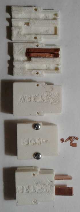
 On the
evenings of the 15th and 16th I printed shells.
Each time I would think, "gee, there's some wasted space there", or
"those hairpins don't need to be so long". At one point I realized that
inside the space of the shell, if the open ends of the "hairpins" were
bent out a bit, they would hit the sides of their space, so toward the
center the hairpin was providing "double" pressure against the plug
blade, making a better connection. And that would prevent the folded
end from being spread apart and losing pressure, too. So I shortened
the hairpins, and hence the whole socket, some more.
On the
evenings of the 15th and 16th I printed shells.
Each time I would think, "gee, there's some wasted space there", or
"those hairpins don't need to be so long". At one point I realized that
inside the space of the shell, if the open ends of the "hairpins" were
bent out a bit, they would hit the sides of their space, so toward the
center the hairpin was providing "double" pressure against the plug
blade, making a better connection. And that would prevent the folded
end from being spread apart and losing pressure, too. So I shortened
the hairpins, and hence the whole socket, some more.
And somehow the shells on the 15th were 13 mm between
blade centers instead of 15. On the 16th I made one 15, and decided
narrower was better. With another adjustment, I ended up at 12.5 mm,
and decided that was a good size.
But that was all without having tried to wire the socket.
I always set aside the wire in my mind "It's just a skinny little
wire." Now I started to think that it would be hard to get fat wires
in. For 50 amps one would want to use #8 AWG wire, if not #6.
Hmm... no, those were definitely not going to go in. Either I was
making 30 amp connectors for maximum #10 wire - at most - or I was
going to have to scale up a bit.
 Perhaps what I really needed was another way to connect
the wires to the hairpins? They really have to stick out from the end
of the hairpin instead of projecting sideways from inside the fold.
Maybe a tab, silver soldered to the ends of the hairpins? More ideally,
a small pipe that could crimp down on the wire. Or more simply, perhaps
just different shaped hairpins with a tab bent right into the closed
end? Before bed, I pounded some #10 wire flat and snipped it at 70 mm.
Then I bent them into that special shape, using a 2.5 mm thick washer
to form them around. The wire could be soldered to the flat part and
hopefully would have enough room to come straight out the back.
Perhaps what I really needed was another way to connect
the wires to the hairpins? They really have to stick out from the end
of the hairpin instead of projecting sideways from inside the fold.
Maybe a tab, silver soldered to the ends of the hairpins? More ideally,
a small pipe that could crimp down on the wire. Or more simply, perhaps
just different shaped hairpins with a tab bent right into the closed
end? Before bed, I pounded some #10 wire flat and snipped it at 70 mm.
Then I bent them into that special shape, using a 2.5 mm thick washer
to form them around. The wire could be soldered to the flat part and
hopefully would have enough room to come straight out the back.
 The 18th was again occupied with other things and I found
little time to get any farther. I did make another pair of the new
hairpins and soldered a #8 house wire onto them (40-55 amps), and a #6
(55-75 amps) onto the other pair. The soldering took a lot of heat and
a big tip on the iron, but it seemed like good joins could be made.
The 18th was again occupied with other things and I found
little time to get any farther. I did make another pair of the new
hairpins and soldered a #8 house wire onto them (40-55 amps), and a #6
(55-75 amps) onto the other pair. The soldering took a lot of heat and
a big tip on the iron, but it seemed like good joins could be made.
It was obvious that my shell arrangements were totally
inadequate for the wires. The hairpins were longer. The #6 wire with
its insulation was bigger than the connector pieces and would need a
very substantial space. Even the #8 insulation was a larger diameter
than the wire holes. It might even be better to have two designs, for
each wire size. But having the wires come straight out the back would
be a big improvement. On to shell design #5!
Before bed
seems to be about the only time I'm
getting to
work on this! On the night of the 19th I changed the shell to
accommodate #8 wires. I even made the wire holes small for a short
section with no insulation, and then larger for the insulated wire to
come out the back. I un-soldered the #6 wire and soldered on a #8 to
the other pair of clips, which is probably a bad sign that it's too
much work making the clips. It seemed to go together pretty well. It
took
substantial force to insert the pins, and without a plug to pull on, I
couldn't pull them back out except with pliers. They hold well and
should make good connections. I didn't see anything I wanted to change
offhand. The printer was warmed up and ready to go, so I just printed
another one the same.
Next, the plug. I wasn't getting very far very fast on
this little project! But I managed to design and print a plug the next
day, Saturday the 20th. It seemed good. Noticed that the bed (still)
wasn't exactly level. I adjusted the right side up a bit, and put the
routine that printed "HAT36V" back in. I made one other small change
and printed another plug. This time, the lettering sort of came out. If
you got the light just right, you might guess that's what it said. I
spaced "H A T" a little farther apart so the printer wouldn't do weird
things between the letters, but I had had enough of 25 minute prints.
I'll assume the next one will be better rather than worse.
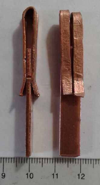
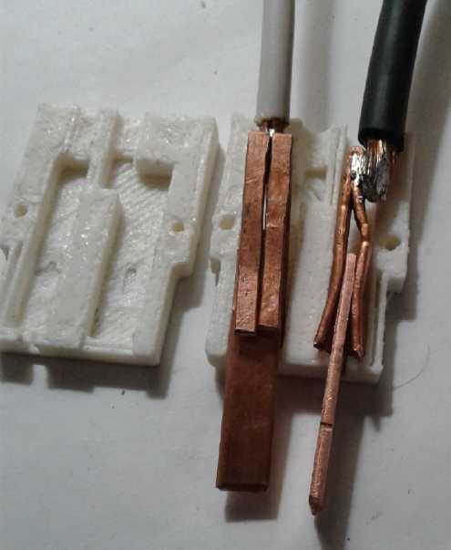
 For the plug,
I came up with a new technique:
since the
wires (#8 AWG) were so fat, I picked a special fastening method and
used them as the means to lock the blades in, to prevent them from
sliding out. I drilled a hole in each blade. But the wire - #8 is
always stranded - was divided so half the strands went on each side of
the pin. The stripped length, about 5/8", was intended that the strands
ended just at the far end of the hole. I pushed many of the strands
into or through the hole from each side. Then when the wire was
soldered onto the blade, it had more than just surface contact,
improving mechanical strength.
For the plug,
I came up with a new technique:
since the
wires (#8 AWG) were so fat, I picked a special fastening method and
used them as the means to lock the blades in, to prevent them from
sliding out. I drilled a hole in each blade. But the wire - #8 is
always stranded - was divided so half the strands went on each side of
the pin. The stripped length, about 5/8", was intended that the strands
ended just at the far end of the hole. I pushed many of the strands
into or through the hole from each side. Then when the wire was
soldered onto the blade, it had more than just surface contact,
improving mechanical strength.
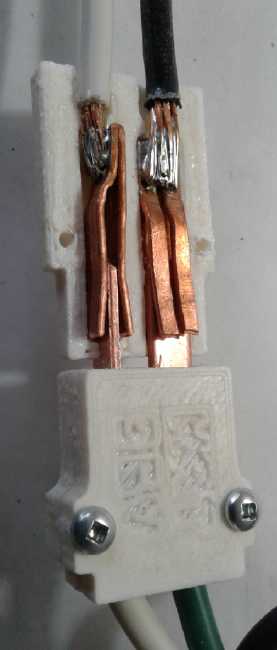
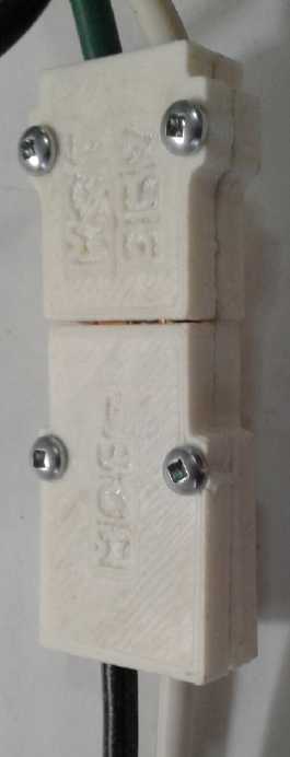 The final
result seemed quite satisfactory in operation.
Considerable force was needed to push the plug in or to pull it out.
But I don't consider it to be excessive. That force is going into
making a good, solid connection for the high currents these are
intended for.
The final
result seemed quite satisfactory in operation.
Considerable force was needed to push the plug in or to pull it out.
But I don't consider it to be excessive. That force is going into
making a good, solid connection for the high currents these are
intended for.
For the smaller plugs, I'd be finished here. Two parts
remain. First is that for such fat wires, distinct designs are required
for #8 and for #6 wire, so the #6 still needs to be done. Then the part
remaining is to make the socket shells out of ceramic instead of
plastic. I wouldn't want to burn someone's house down owing to heat
from a poor connection melting a plastic socket. This will be a
substantial project in itself.
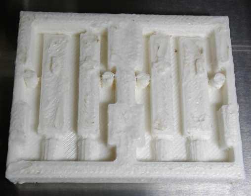 I hadn't given
much further
thought to making molds for the
ceramic version, but it started to dawn on me that I could do them too
on the 3D printer, using the same design. On the night (again late at
night!) of the 24th I added a new block of plastic to completely cover
everything made before, and a "difference" command. This made it into a
big block with the socket design inside of it, "inside out" with spaces
where the solids would go and vise versa. Then I added "scale" by 1.15
times in each direction, to compensate for shrinking of clay during
drying and firing. I had to drop the lettering, which would have
printed in the air at the top. (But I could make it into a plastic
stamp to stamp into the outside face of the clay.)
I hadn't given
much further
thought to making molds for the
ceramic version, but it started to dawn on me that I could do them too
on the 3D printer, using the same design. On the night (again late at
night!) of the 24th I added a new block of plastic to completely cover
everything made before, and a "difference" command. This made it into a
big block with the socket design inside of it, "inside out" with spaces
where the solids would go and vise versa. Then I added "scale" by 1.15
times in each direction, to compensate for shrinking of clay during
drying and firing. I had to drop the lettering, which would have
printed in the air at the top. (But I could make it into a plastic
stamp to stamp into the outside face of the clay.)
The resulting mold looked rather rough and I could see it
needed a couple of changes, but I decided to try it out. I have a
feeling I'll have to scrape or sand some of those surfaces smoother,
and probably put a few holes in the bottom of the mold to push the clay
out from. If I got the slicer software for the new printer
installed, it would already be a lot smoother. (I would of course have
to remove the clay still damp, since it would crack if it shrank still
in the mold.)
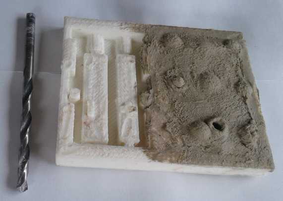 On the 25th I tried it. I was
sure I would need holes to
push the piece out of the mold, so I drilled some in one side. I found
some clay that was rather too damp (no doubt had been a 'slip') along
with other bags that were too dry to work. It filled the mold nicely,
but when pushed, the spot right above the hole just bulged or opened.
On the 25th I tried it. I was
sure I would need holes to
push the piece out of the mold, so I drilled some in one side. I found
some clay that was rather too damp (no doubt had been a 'slip') along
with other bags that were too dry to work. It filled the mold nicely,
but when pushed, the spot right above the hole just bulged or opened.
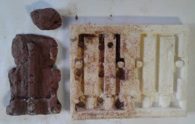 Then I found
"Log End Sealer" (Bow River Craft Woods), an emulsified
wax solution, and painted some in to make the mold more slippery. Then
I tried some red clay that seemed like a good consistency, not too wet
or too dry. This time if I pushed on each hole, the piece started
coming out. But the edges in the thin slots broke away and stayed in
the mold. Looked like it wasn't going to work readily. Back to square
one.
Then I found
"Log End Sealer" (Bow River Craft Woods), an emulsified
wax solution, and painted some in to make the mold more slippery. Then
I tried some red clay that seemed like a good consistency, not too wet
or too dry. This time if I pushed on each hole, the piece started
coming out. But the edges in the thin slots broke away and stayed in
the mold. Looked like it wasn't going to work readily. Back to square
one.
The next idea was to make an oversize socket, file or
scrape everything as smooth as I could, then pour some flex mold
compound in it and fill all the spaces, then turn the whole thing over
and put it in a shallow box to make a mold, around 'actual' (oversize)
socket pieces. Hopefully the clay wouldn't stick to the flexible
rubbery mold if I made it as smooth as possible and coated it with wax.
I bought the flex mold compound years ago and had trouble
using it because bubbles would form in it. There were instructions for
putting it in a vacuum until all the bubbles came out, but I hadn't had
a vacuum to put it in. Now I had a vacuum pump and a container. Maybe I
could use it this time!
But before that I looked at the 3D plastic mold again, and figured that
if I
could just cut off the bottom and set it on (or clamped it to)
something
flat, everything should still hang together (except the bolt holes),
but I could push the clay out the top through the big gaps in the
bottom. I could even look at the bottom and make sure the clay had gone
into every nook and cranny... even fill any gaps from the bottom. The
bolt holes could be punched in after with a piece of brass
tube.
How to cut or file or plane the bottom off? Hmm, wait!
Easier
just to add a couple of instructions in the OpenSCAD file and 3D print
a new one already missing the bottom!
New Type of Circuit Breakers: "In-Line", Faceboard Mount
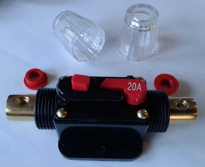 When I ordered
three more "PowMr" charge controllers I
noticed the same outfit had "in-line circuit breakers". In this case
the pictures were inadequate and I couldn't really tell what I was
looking at, especially the size. I thought they looked pretty tiny.
Something told me I should order some anyway.
When I ordered
three more "PowMr" charge controllers I
noticed the same outfit had "in-line circuit breakers". In this case
the pictures were inadequate and I couldn't really tell what I was
looking at, especially the size. I thought they looked pretty tiny.
Something told me I should order some anyway.
They turned out to each be 4" long, with holes to screw
them onto a flat panel. Instead of a "breaker box", they could be the
terminations for various wires on the face of a low voltage panel.
Lines from each panel or sets of panels would go to a breaker, then to
the charge controller, inverter or other destination. The battery bank
could go to a fairly high amperage breaker before going to any
equipment. If there are any shorts or if the equipment blows and shorts
out, the breaker would blow and protect the batteries - and the house.
The wires need no lugs on the end and are securely screwed
down (hex wrench) inside the breaker's "pipe". And while the breakers
are exposed themselves if
mounted in the open, they completely enclose the connections - no bare
copper showing anywhere, which is better than any other breaker.
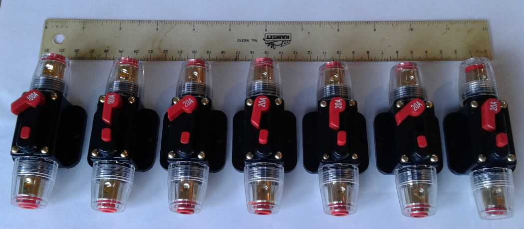 The flat surface mount breakers. I forgot why I
ordered a whole bunch of 20 A and no 15s,
The flat surface mount breakers. I forgot why I
ordered a whole bunch of 20 A and no 15s,
but returning to the page, 20 A were the smallest.
I was rather proud of my circuit breaker box with the
"Blue Sea
Systems" circuit breakers. Still these new breakers seemed to offer a
simpler way to connect up the DC components and circuits, and one can
visually trace the circuits and see what breaker connects what to what.
New PowMr 60 amp MPPT Charge Controller
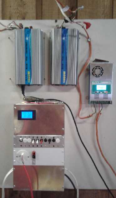 Except for the
noisy 'always-on' fan, the little
MPT-7210A boost charge controller was very much
to my liking. It was completely programmable and it did everything I
wanted. It raised the 25-35 volts from the solar panels to 41.0 volts
[my setting] to charge the 36 volt batteries. It could be turned on or
off and came on automatically in the morning. It drew its power from
the panels so it used nothing from the batteries. The only problem was
that it was only 10 amps. If the power went off, that would take (eg)
at least 10 hours to recover 100 amp-hours into the batteries - more
than a day. So it would be the restricting factor in how much power
could be used per day.
Except for the
noisy 'always-on' fan, the little
MPT-7210A boost charge controller was very much
to my liking. It was completely programmable and it did everything I
wanted. It raised the 25-35 volts from the solar panels to 41.0 volts
[my setting] to charge the 36 volt batteries. It could be turned on or
off and came on automatically in the morning. It drew its power from
the panels so it used nothing from the batteries. The only problem was
that it was only 10 amps. If the power went off, that would take (eg)
at least 10 hours to recover 100 amp-hours into the batteries - more
than a day. So it would be the restricting factor in how much power
could be used per day.
Looking on line, I discovered that it was a pretty rare
type. There were very few other boost charge controllers on the market,
and they weren't higher powered either. I didn't fancy designing and
building my own. It seemed the only way to get a higher power boost
controller would be to connect several of them all feeding the same
batteries. Two might be all right for 20 amps. Adding multiples seemed
like a troublesome arrangement.
So to get a higher powered charge controller it would have
to be a buck converter unit - one that reduces voltage from the panels.
That means to get 40 volts, one has to have panels producing 50 or more
volts. That means wiring at least two panels in series and having a
dangerous higher voltage. Apparently there were no other options. Oh
well, at least it's only in the panel wiring and not the 36 volt house
distribution wiring. Putting panels in series here is undesirable not
only from an electrical safety perspective, but because they do get
shade, and a shaded panel, even partly shaded, kills the whole series
string (here, just two panels) instead of just one panel.
I ordered a 60 amp "PowMr" charge controller. (There were
four models 30,40,50 and 60 amps, but the 30 amp one was only a few
dollars less than the 60, so going lower make virtually no sense.)
It'll be needed to run electric hot water, and if the grid goes down
the "off grid" battery system will come into very heavy use to also run
the well pump, freezer and fridge. I ordered again from "Y Smart"
store, which seems to be the outlet for "Y Solar" products. It arrived
on the 16th. So now I have, all from "Y Smart", "Y Solar": four 1000
watt grid tie inverters (3 were in use), a 36 volt to 230 volt, 2500
watt inverter, and a 60 amp MPPT charge controller.
I was a bit leery: it's supposed to select between 12, 24,
36 and 48 volt batteries automatically, depending what you hook it up
to. Two of the divisions, 12-24 and 24-36 seem clear enough. But the
division between 36 and 48 volts is 39 or 40 volts. That seems
dangerously low. The NiMH cells sit at 39 to 40.5 volts after charging.
(If I pushed the charging they'd hit 42.6 volts.) By default the unit
itself wants to charge a 36 volt battery to 42.6 (adjustable - I set it
to 40.5). And I've heard of a unit before that was supposed to be 12-24
volts, but once it had charged the 12 volt battery sufficiently, it
then decided it must be 24 volts and tried to bring it up to that
level! However, it didn't seem to have a problem.
I mounted it, removed the
10 amp unit, and connected the
new one toward evening. Sure enough, with 27 volts from the panels it
claimed it was "night", showing a little crescent moon with two stars
in the cusp. Late afternoon on the 17th I put the two pairs of ~250
watt panels in series. It liked that better and started charging the
battery. 1000 W / 40 V = 25 A max to the batteries. 1000 W / 54 V
(Vmpp) = 18.5 A. Those currents certainly shouldn't tax the 60 amp MPPT
controller.
Next question is, does it realize the battery is 36 volts
and not 48? It started out under 39 volts (having not been charged that
day), but of course the charging itself soon brought it up over 39 and
near 40 - the voltage it says decides whether it will consider it to be
36 or 48 volts. It seemed to be saying the battery was almost charged,
so that was a good indication that it had set itself to 36 volts. But I
changed the shutoff point down to 13.0 volts (13.0 * 3 = 39.0 volts).
The battery was already at 39.7. It kept trying to charge it further.
So I took out a bolt to disconnect the solar panels. I didn't want it
trying to fry my batteries and maybe start a fire before I get up in
the morning to see what it's doing!
I noted the manual had a "reminder" to disconnect the
power and reconnect it to be sure it had taken the setting. The next
morning (18th) I disconnected the panels, then the battery, then
reconnected them. That worked. Apparently every time you make any
adjustment, nothing changes until the unit is powered off and then on
again. Since there's no power switch, and since (like most of them) it
says to connect the battery before the panels, this is a pain in the
butt! And it seems completely needless. It could easily ignore all new
settings and then apply them when the button goes back from "program"
to "monitor".
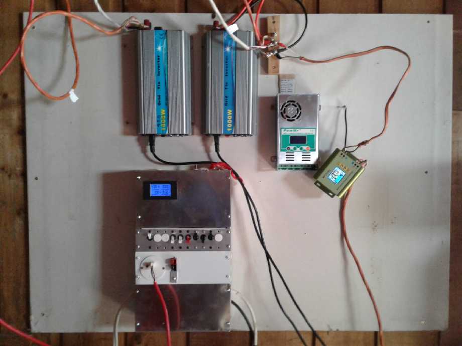 To put the
panels in series, I had to disconnect them from
the grid tie inverter, which wouldn't stand double voltage. Unless I
start running something significant from the DC system, the main effect
is to have lost 1000 watts of panels going to the grid. I now had the
unit required for full "off grid" operation, but I decided to put
things back the way they were, with the 10 amp "boost" charge
controller. If I needed it, it was just a few wires at the equipment
panel to move around to reconfigure it.
To put the
panels in series, I had to disconnect them from
the grid tie inverter, which wouldn't stand double voltage. Unless I
start running something significant from the DC system, the main effect
is to have lost 1000 watts of panels going to the grid. I now had the
unit required for full "off grid" operation, but I decided to put
things back the way they were, with the 10 amp "boost" charge
controller. If I needed it, it was just a few wires at the equipment
panel to move around to reconfigure it.
First I made a three bolt terminal block from a piece of
wood (genuine lilac!) to eliminate the wiring connections hanging in
the air.
Then at the end of the month I ordered a heavy DPDT switch
to put the four solar panels either in parallel or in series (4. or 2+2
for double voltage).
When I went to put the MPT-7210A back, I was wishing I had
the in-line circuit breakers I had recently ordered (they hadn't
arrived yet) so I wasn't
screwing live wires into the 10 amp controller, and with its metal case
so close to the terminals. As if on cue, while I was screwing the first
one in, both battery wires touched something and shorted. There were
big sparks. The end melted off both wires, there was a chunk burned out
of the case with the end of one wire stuck to it on the inside, and the
tip of the Phillips screwdriver was ruined. Somehow, after cleaning it
up, the wire clamp screw still turned, and the MPT-7210A still worked.
Grounding!
Somehow that got me thinking that the whole DC system
was floating, ungrounded. Wiring was spread from the panels on the roof
to the wiring through the house. (Well, just one house wire so far.)
And now it could have over 70 volts on it. And what about atmospheric
static? I took a piece of house wire and grounded the breaker box to a
convenient nearby AC outlet box, which was of course itself grounded.
(It was the box the grid tie inverters were plugged into.
When I unplugged them along with the power meter, the KWH reading reset
to zero. I guess that's what it wanted batteries for!)
"Standard" AC Wire Colors NEED TO BE CHANGED! and Unified with DC
Conventions
I used a black [insulation color] wire for the ground, the
same color as all the other DC ground wires. I wasn't into trying to
run wires through the finished wall to hide them when all the equipment
is there wired on the front of the wall panel, so I just ran it along
the wall in front. (The building supply here doesn't seem to have
Panduit wiring raceway covers.) Of course a black wire sticking out
from behind the cover of an AC outlet box would give an electrician the
willies. I wrapped a piece of green tape around it near the outlet box
end.
Earlier I had listened to a video on wiring solar systems.
The presenter went into wire colors at great length. It got me thinking
- not to mention disgusted with the conflicting colors. I suppose it
has lately been, perhaps almost subconsciously, realized by many people
that wire colors are a growing problem as DC and AC systems with
incompatible wire colorings are combined in increasingly complex
building wiring systems. I'd like to shine a spotlight on that. In
spite of a century of tradition, I'm going to say it: IT NEEDS TO BE
CHANGED. The problem is that for DC circuits, red was chosen for plus
and black for minus - which is usually ground. And the actual ground is
normally negatively charged compared to the sky. Black is the color of
dirt, earth, ground. And it is the absence of color, of light and of
energy. It is the night sky. What else would black be but ground, zero
volts, no energy?
But for AC, for some reason which seems to me to defy all
sense and intuition, and also incompatibly with DC, someone chose black
to be the live power wire. It's plainly wrong. This is the root
of the problem. Logically then "no power", "neutral" became white - the
color that is the inclusion of all colors, the maximum of emitted
energy. Anyone from another planet, or just not familiar with our AC
color convention, would immediately guess wrong which wire was which.
(And what strange, convoluted thinking made green with a
yellow stripe a "ground" in AC systems? That's the colors of a snake.
It looks like a dire warning: Don't Touch!; that it will have a deadly
strike.)
If we switch now, in a couple of hundred years practically
all of today's wiring will have been replaced and the problem will be
over. It can be over immediately for new installations. Simply swapping
black and white would obviously lead to great confusion and numerous
accidents, so the next question is: in practice how can it be changed?
The answer is to pick entirely different colors, and not use black or
white at all. Brown - any shade of brown or darker tan distinguishable
from black - is pretty nearly as good an "earth" or "ground" or
"neutral" color as black. A yellow wire for an AC hot phase is clearly
distinguishable from white, and yellow is a good warning that it's
"live". Manufacture of cables with black and white wires would cease,
and brown and yellow cables would be made instead. Everything else
could remain as it is. If one must use wire with the most common colors
as available from the local hardware for DC wiring, brown and yellow
are okay for minus (brown ground) and plus (yellow hot). The ambiguity
of whether Black or White is "hot" would be gone.
Once most old buildings and their wiring have been
replaced in 100 or 200 years, the choice of colors can be revisited.
Ground could well be black for all circuits. AC neutral can remain
brown. Hot could go to being white, but I kind of like
yellow for hot myself. It's a warning warning color.
The alternative, to leave it as is today, is to perpetuate
the problem, year after year, decade after decade, century after
century. The number of
installations and the problems caused will multiply and multiply.
Herein is an good example of how our society lurches from
one problem to the next, just "putting out fires" - ever more and
bigger ones - without addressing the underlying causes to solve
problems at their root for the long term. It's the same way we are
dealing - failing
to deal - with all our social and political problems - how can our
society not collapse? After all.... the Egyptians, the Greeks, the
Romans... the
Incas, the Anasazi... the Easter Islanders -- It's not what the
ancients
did that caused their civilizations to crumble. It's what they left
undone.
Hello NEMA? IEEE? CSA? Where are you? Nobody thinks it's
their business to fix underlying problems. Maybe it will take Social
Sustainability Design Teams to address all long term issues?
Let's "go metric" on AC wire colors - Change white and
black to brown and yellow so they can be unified with DC colors and
with common sense into one system, and discard the old illogical and
conflicted tradition!
---
Here's my suggestion:
Black, Green: ground, zero volts. (Green will still be needed in AC
wiring until
black as 'hot' wiring has passed out
of existence over a very long time period.)
Brown/Darker Tan: AC neutral, alternate DC ground, zero volts
Red: DC "Plus" voltage
Yellow, Orange, Blue: AC "hot" wires
Violet, Gray, later White, Green: Unassigned.
---
Of course the local hardware store (for the near future)
is likely to have only brown and yellow house wire, so yellow will have
to be used for DC "+". But at least there will be common agreement that
the brown is the ground wire, hence the other one must be "hot" or
"plus".
36 Volt Solar Hot Water Heating
The video I watched in March showed that a solar water
heating panel starts heating quickly, but as temperature rises it has
considerable losses in the collector and in the hot water piping loop,
and the heating slows down a lot. To finish heating the water a simple
electric tank heated by solar PV panels, while heating slower at first,
ended up doing a better job. This would depend a lot on the hot water
heating setup and length of pipes in the heating loop, but it suggests
a double system with a solar water preheating loop and an electric tank
where it gets up to the desired temperature. This is of course the
"traditional" solar assisted hot water system. If the electric tank is
heated by solar power, then the system can be 100% solar when the
weather is sunny.
After the experiment with the small hot water tank showing
how slowly a 120 volt heating element worked at under 40 volts, I first
thought to make the coiled pex pipe hot water collector. I made the
base and sides for the box per the directions in the video, but found
that it didn't look like it would accommodate more than 80 or 85 feet
of my 100 foot pex pipe. I didn't want to cut it and make it smaller
than it could be, but that meant making a new somewhat larger box, and
(having cut the one piece) I didn't have a suitable piece of plywood.
There the project sat.
36 Volt Electric Water Heating Elements
The other idea had been to find a heater element for the
tank that would work heat reasonably quickly at 36 volts. Getting under
150 watts by running the tank's 120 volt element at 36 volts heated
water much too slowly to be practical. Upon searching for it, I found
there actually was such a thing as a 36 volt water heater element, 1200
watts. There were three choices from a maker on AliExpress.com:
* 1" pipe thread fitting with two separate elements. This could
presumably be used at 600 or 1200 watts. (25$C)
* 1.25" thread fitting with three separate elements. This should allow
400, 800 and 1200 watts. (32$C)
* Just as I clicked the page closed I noticed: A flange fitting one
with four screws. That would fit some other tank than mine, so I didn't
look further.
L: 1" - R:
1.25"
I ordered the 1.25" one, thinking it might fit the threads
in the tank. (The fitting on the tank looked pretty big. More likely
either heater will need a reducer fitting.) 1200 watts at 36 volts is
33 amps. Even in direct sunlight four 305 watt panels would hardly
maintain full voltage. I was glad the maker put multiple elements in
each heater to give lower power options.
Regular Hot Water Tank as Combo Solar and Grid Water Heater
The common plumbing of solar hot water is to install an
extra water tank for the solar, the "preheat tank". Whatever
temperature this comes out at feeds the regular hot water tank,
reducing the electricity it needs to finish heating the water. This is
of course a big plumbing project, and the more so in an existing
building.
At the end of the month I started thinking that a regular
water tank could be treated like two tanks if one didn't commonly need
more than half its capacity. That's because water, if not disturbed,
and if heated from the top, has a great tendency to stratify into
different temperature layers.
I as a single guy could probably do this
just with a 40 gallon tank. The upper element would heat the top part
of the tank from the grid as usual if the whole tank was cold. But when
it shut off, it wouldn't switch the power to a lower element to heat
the bottom half. Instead, the lower element would be a 36 volt one
connected to the solar supply. In essence, the lower half would become
the solar preheat tank and the upper half the regular tank. If the
solar heating was sufficient the whole tank would be hot. When hot
water was used, the bottom of the tank would refill with cold water and
it would reheat more gradually with a 36 V, (eg) 1200 W element instead
of from the grid with the common 240 v, 3000 W one. Only if the solar
hadn't heated the water sufficiently - if it was being used too fast,
or if there wasn't enough sun - would the 3000 watt grid element come
on.
Note: On May 4th I reconnected the tank as 120 volts instead of 240 in
the breaker panel. That changes the elements from 3000 watts to 750
watts. Now if there's solar power, and if hot water is used in the
daytime, the demand doesn't overpower the solar system. That's one
step! (see April in Brief for more.)
Polyethylene Pipe Preheating
While ordering 36 volt water tank heaters and other 36
volt solar equipment, I started rethinking the direct solar water
heating. My kitchen sink rain water system was going to come from a
barrel or tank on the roof (which would have to refilled occasionally
by a pump). That would neither get too hot (even if it was insulated)
nor have much pressure. Why not have a simple polyethylene pipe heating
coil? That would preheat the water. Obviously it will be easier and
faster for the electric tank to heat 30°C than 10°C water to
50-55°C. The electricity is then available for other things.
I had a coil of 1-1/4" fat PE pipe already. And as I write
(12th) I remember I have a swimming pool pump on a shelf in the
workshop, to circulate the water if thermosyphoning doesn't do it. It
would seem there's not much else to buy except a few pipe fittings. As
usual, it becomes "just" (ahem) a matter of finding the time to get it
done. Then something changed and I decided not to do it. Next!...
Chemical Free Iron Filters for Well Water
On the 25th the whole position was revolutionized. My
neighbor told me about his new "aeration" water filter system. The
dissolved ferrous iron (and other things) in the water are first
aerated in a tank with an air injector. This oxidizes it and turns it
into insoluble ferric
"rust" or yellow hydroxide. From there it goes through the regular sand
filter tank and is filtered out.
One web site said they weren't worth getting because they
clog and you'd have to clean it out every six months. He was probably
greatly exaggerating the problems since he was trying to sell a
different system, but even if such frequent cleaning is necessary...
it'd be worth it!
I'm sure my well here will never run dry. Once I have one
of these installed, I won't need to collect rain water to get
(relatively) pure
water any more. And my sinks, toilets, bathtub and dishes will (more or
less) stop
being stained brown. I can just hook the under-sink hot water tank up
"normal" to the rest of the plumbing. Yay!
I found one of these "chemical free iron filters" for a
whole house,
"Rainfresh", at Home Hardware. It apparently did all the regular sand
filtering with daily backflush too, in a single unit. The one customer
product review said something along the lines of that it wasn't 100%
but that the iron staining was dramatically reduced. I ordered one.
That would take me back to a pex pipe coil for a hot
water
collector if the preheat is tied in through the regular water under
pressure. And a tank that takes pressure. I do have all the major
parts, even a brass water tank. But is it worth all the plumbing?
Easier just to add more electric solar panels if needed, to help heat
the electric tank!
Need for voltage controlled operation... & Components for that
If one was to dedicate a couple of solar PV panels
to heat a hot water element just when the sun was shining, it should be
fine. However, if such a heavy load was hooked into the battery supply
it would run any time and it might kill the batteries at night or if
there was no sun. What was needed I've talked about making before: a
low voltage cutout. I had a fairly sophisticated control in mind: one
cutout would have the appliance run preferentially when there was power
charging the batteries (sunshine or wind). One doesn't want a heavy
load to run the batteries down too far and have nothing left for lights
at night. The other would definitely shut it off to protect the
batteries if they got low. (One might have one "low battery" relay shut
everything off. But it would be better to power down the heavier and
less time sensitive loads before (eg) low power lights and notebook
computer. Perhaps this is an argument for more solar panels and more
battery capacity.)
But... Duh! Might there already be at least a simple low
voltage cutout control? I looked again at Aliexpress. There were a
bunch of them, but they were all for 12 volt batteries only. Not for
solar panels, not for any other voltage. And I suspect they didn't have
any (or enough) time delay built in in case turning off a load
immediately raised the voltage back above the turn-on point. It would
be bad to have an appliance "flickering" on and off.
Of course, one might just have semi-dedicated panels along
with a grid tie microinverter. If the water was heating, the inverter
wouldn't find much power from the panels, but when it shut off, the
panels could supply the grid. At night there would simply be no power,
no batteries to drain. ...Would it not be better to have the voltage
control?
A few days later, I started to think that a 12 volt
shutoff might be made to work after all - assuming it shut off with a
mechanical relay. It could sense the voltage of just one of the three
12 volt batteries making up the 36 volts, eg, from the 24 to 36 volt
levels, and shut off when that one was below the setpoint. All three
batteries charge and discharge together. I'll have to get on line again
and see what looks like it might work.
I had also noted that I could program the "PowMr 60A"
charge controller to do this sort of operation by setting the output ON
and OFF voltages appropriately. But the drive was limited to 5 amps -
not much for a water heater. On the last evening of the month I watched
a video ("Offgrid Steve") who showed how he programmed his Schneider
"Xantrex XW 60 150" charge controller to turn on an "aux" output - for
his water heater - when the battery charge was high (sun shining). The
ON and OFF voltages could be programmed, along with delay times for
trying again (he had 30 seconds) and before shutting OFF once ON (15
seconds) - pretty much what I have been after. He ran his water heater
from AC through an inverter, so he couldn't use a DC output directly -
and doubtless as with mine the current rating wouldn't have been high
enough anyway. In fact, his "Aux" output voltage could be set only to
from 5 to 13 volts, not to the whole battery voltage. So he had his
"aux" output drive solid state relays to enable or disable the water
heater. These take very little current to run but can switch very high
AC current loads.
Perhaps that was the answer: Use the PowMr "output"
terminals just to turn a relay (or power MOSFET) on and off, which
would enable the high
current (DC) water heater(s) when the sun was shining. I don't think
delays can be programmed on my unit, and the output is the whole
battery voltage. Hopefully reasonable delays are built in. I should
check it out.
More Better
LED
Lighting
It looks like I'll be doing some solar installations for
others needing - in fact as the main objective - LED lights.
Heatsinks for LED Light "Cob" Panels (etc)
Why I never thought of it before I don't know. As with low
voltage water heating elements, cheap DC to DC down converters and so
many other things, there was a vexing problem but I just never thought
to look for a ready made solution. I think a big part of the problem is
that such things were never available in times past for purchase at
economic prices. (And I was almost always on a tight budget.) They
would be a "specialty part" for which one would pay through the nose
for the simplest things, which were or could be mass produced, but the
market was too diffuse by area to bother to turn them into a readily
available product.
Cheap postal shipping for little things, or reliable
tracked shipping for things perhaps worth stealing, the internet, and
Chinese businesses have changed that. The Chinese will put any little
thing into a bubble envelope and send it across the world for a few
dollars where a North American firm would have a considerable minimum
order before they could be bothered, then they send it by costly
courier, and it's enough money to attract the attention of customs, to
which the courier's "brokerage" service would add a big fee to bring it
over the border into Canada. So you order 5 overpriced heatsinks
instead of 1 to make up the minimum order, then pay half as much again
to get them to your door. Your 3$ heatsink has cost you 55$. At least
you have 4 more in case you need another one!
On Aliexpress are all manner of aluminum heatsinks for
electronic devices for low prices, including some sized for cooling the
LED "cob" light panels. I ordered some.
DC to DC Down Converters to run 12-24 Volt Equipment From 36 Volts
I got a set of ten "5 amp" DC to DC
down converters to get 12 volts output (in fact fully adjustable 5-30
V) for 20 $C total.
This will greatly simplify putting 12 volt LED globe or flat panel
lights together for off-grid sales. Then again... whole 12 volt panel
lights from China are pretty cheap too. No doubt just a matter of
looking and picking some out.
I also got some higher current DC to DC units with decent
heatsinks for heavier 12 to 24 volt loads. I find it exciting that with
these, running 36 volts means you also have both 12 volts and 24 volts
at hand.
 36 volt (or less) fully regulated DC to DC down
converters.
36 volt (or less) fully regulated DC to DC down
converters.
Top row: some 2$ ones with solder connections, for low power: "5A 75W
XL4015"
(XL4015 is the single chip DC to DC converter chip number). BTW they
get hot running just 10 or 15 watts, 12 volts!
Front row: the 5$ ones with good heat sinks, screw-down connections -
"DC CC 9A 150W, 300W"
300 watts, or even 150, is a lot of power - hmm! But (eg) a 12 volt
camping cooler is only ~50 W
Single trim pot (blue square with screw): adjust output voltage
Second trimmer: set current limit
CNC
Router/Plasma Cutter/Drill
On the 13th my "GeckoDrive G540 Multi-Axis Step Drive"
arrived. Then the parallel to USB cable. Then the "gender changer" to
connect the female parallel plug of the cable to the female plug of the
Gecko. (Why is this so absurd? 3D printers just have USB. Most CNC
controllers have parallel ports - for historic reasons? - even tho
computers don't come with them any more.) Now I should be able to set
up the CNC table, except for software. There were things to download,
but I hadn't been able to get anything to work.
Everything, of course, when I find the time.
My
Solar Power System
(All
times are in PST: clock 48 minutes ahead of sun.)
Date House KWH, Trailer Roof KWH - day total KWH made [power
co. meter] weather, usage...
March 31st 141.41, 134.61 - 12.00 [65331@9:00, 334@19:00] sun. Turned
car
back on with 1.5 KW/120 V charger to finish from solar.
April 1st 148.59, 140.16 - 12.73 KWH [65349@9:30, 351@20:00] sunny.
2nd 154.98, 145.04 - 11.27 [65361@21:00] thin chemtrails, clouds later
PM. Charged car @1500 W from solar after 55 Km drive previous day.
3rd 161.62, 150.27 - 11.87 [65371@9:30, 378@19:30] more of same slight
overcast.
4th 163.66, 151.92 - 3.69 [65405@19:00] rain AM, cloudy all
day.
5th 166.61, 154.21 - 5.26 [65442@20:30] clouds & rain.
(bath, 85 Km drive & charge.)
6th 168.28, 155.52 - 2.88 [65474@23:59] clouds, rain (55
Km)
7th 172.28, 158.69 - 7.17 [65490@19:00] rain, clouds, sunny
hour, deluge, clear evening. (bath, laundry)
8th 174.49, 160.43 - 3.95 clouds & rain (then stars)
9th 177.61, 163.02 - 5.71 [65523@19:30] clouds and showers
(stars during the night)
10th 181.84, 166.34 - 7.55 [65531@10:30; 65541@19:30] clouds
11th 188.13, 171.36 - Oops, didn't read until 10 AM on 12th; already
making ~1KW. light clouds
12th 191.30, 173.64 - 8.38 avg.11th, 12th [65581@10:30,
587@19:00] light/medium clouds - drove 55 Km both evenings (10th, 11th)
13th 193.71, 175.67 - 4.44 [65612@18:30] rain, cloudy until late
afternoon. Moon & stars - what's wrong with this picture? 55 Km
& chjd. this day.
14th 200.19, 180.92 - 11.83 [65625@10:30,627@18:30, 636@02:00]
sunny!...AM. PM: clouds & rain... then stars. Bath PM.
15th 202.42, 182.66 - 3.97 [65649@19:30] clouds and
drizzle/rain all day
16th 207.08, 186.30 - 8.30 [65666@19:30] RAIN! A couple of
sunny breaks.
17th 208.67, 187.45 - 2.74 [65691@17:30] overcast
18th 2.30 [e.5.63 KWH], 191.85 - 10.03 [65720@21:00] sun & some
clouds. House solar meter was accidentally reset to zero midday. (It
got unplugged. Estimate "e." is based on an "average ratio" of about
1.28 to 1 compared to the trailer roof. [Theoretically it should be
1.32 to 1 but not according to readings.] Well, the ~250 watt panels
are 5 to 8 (?) years old now. If they are only at ~96% it's
understandable.The 250 W panels were actually off line part of the day
for tests of the new "PowMr" DC buck charge controller. The 'e.' is
about what the house would have given if it had been on line all day.
Yikes what a lot of explanation for a simple little glitch!)
19th 7.61, 195.93 - 9.39 [65732@20:00] sun & some clouds. Drove to
Masset, 190 KM total, but can't recharge gas tank in Toyota Echo.
20th 11.68, 199.15 - 7.29 [65750@19:00] clouds, some rain. 55 Km
21st 13.07, 200.50 - 2.74 [65773@19:00] overcast, rain.
22nd 18.86, 205.36 - 10.63 [65787@20:30] AM clouds, PM sun.
23rd 24.82, 210.37 - 10.97 [65805@20:00] clouds, rain and sun (~8 KWH
to charge car)
24th 29.69, 214.04 - 8.54 [65819@10:00, 65826@20:00] mostly
cloudy, some sun. Drove 55 Km.
25th 33.65, 217.40 - 7.32 [65862@20:00] sun & clouds,
bit of rain, 55 Km
26th 39.19, 221.74 - 9.88
[65873@10:00, 65877@20:00] sun & clouds, bit of rain
27th 44.09, 225.71 - 8.87 [65894@20:30] Sun & clouds
28th 52.32, 232.35 - 14.87 [65915@20:00] Finally, a sunny day!... and
then a sky full of chemtrails all day until evening. Laundry.
29th 61.16, 239.09 - 15.58 [65924@10:30, 926@17:00] Sunny - NO
chemtrails. 55 Km but only charged car 3 hrs. at 1500 W while sun was
out.
30th 69.91, 245.80 - 15.46 [65940@9:30, 942@19:30] Sun. Few chemtrails.
Finished charging car (5 Hrs at 1500 W from 9:30)
May 1 77.40, 252.05- 13.74 [65954@11:30, 959@21:00 ] very light
overcast/chemtrails. Sunny later PM. Drove 55, started charging car
May 2 82.13, 255.88 - 8.56 [65965@9:30, 975@20:00] clouds with sunny
breaks. Finished charging car but not much solar.
May 3 86.79, 259.41 - 8.19 [65987@13:00, 991@19:30] Clouds.
May 4 90.24, 262.32 - 6.36 [66000@10:00, 009@19:30] clouds. again. 55
Km & 2/3 charge car.
May 5 93.80, 265.58 - 6.82 [66022@9:00, 030@21:00] clouds. A couple of
short sunny breaks. rest of charge car.
May 6 [66040@10:00] WHEN will I get this April newsletter out?
As can be seen daily consumption dropped with (somewhat)
warmer spring weather, from over 30 KWH per day to under 20. The
average for the first ten days in March in freezing weather was 30.
Overall March average was 26 and the last ten averaged 22. The first
ten days in April averaged 20. But nights stayed cold the whole month,
so I continued to use considerable bedroom heat and also turn the
trailer heater on at night, not to mention still burning firewood. (I
may have planted some things outdoors too early.
Better to keep them inside to grow faster when it's too cold.) I had
baths more days than
not to combat little red dots that keep appearing on my upper legs. Can
nothing eliminate them? (Then I got shingles on my head. Much worse!)
The middle 10 days was still 21 KWH per day and the last ten it was 19.
The start of May seems to be down to about 17. The reduction in usage
as warmer weather [finally] comes is as significant as the increase in
solar production, which went from 12.73 KWH on April 1st to about 15.5
on [the rare] sunny days by the end of the month. Sunny days definitely
cut down on the amount used from the grid. Forgetting to turn on the
heater in the trailer for the night also saves 3-4 KWH.
Sometimes consumption seemed surprisingly high, but of
course the figures include charging the electric car. I drive maybe
about every second day, but being out in the country now they are
always long trips, most typically 55 or 85 Km round trip, which should
take about 8 and 13 KWH to charge after but actually seem to take
somewhat more. If that was gasoline it would
cost far more than it does, and the solar panels would give zero assist
in refueling. (Distances around Victoria being short and taking few
highway trips when I lived there, since I moved I've been driving at
least three times as many miles per year!) I usually used the 3.8 KW
charger, which didn't give the 1.9 KW from the solar its best chance to
help. Occasionally I took more advantage by using the 1.5 KW charger in
a regular outlet so much of the power came from the sun, but usually
that occupied a later afternoon and (with unplugging for the night) the
whole next morning and into the following afternoon - 8 or 9 hours
total. Often that was impractical, and then only if it was sunny both
days.
The sun still disappeared behind the trees after 4 PM,
later toward 4:30. (And I must point out again that 4 PM PST by the
clock here is
only 3:12 by the sun - just mid afternoon.) But it was still visible
between
the tree trunks and by mid April the panels continued to put out a
couple of hundred watts even to 6:30 PM, and tens of watts for yet
another hour. Thus one sees that without the trees, there would be
substantially more daily collection. Because the trees are in a
north-south row near the house, the higher sun made less difference
than might be
expected. At the trailer however, a little farther away from the row of
trees, the full sunlight collection period period did gradually extend
another hour. It's definitely a better location for solar panels.
Until almost the end of the month, only the first had had
full
sun all day, hence it also had the greatest solar output. Half the days
gave under 2/3 of "full" power. Nine days were quite poor making less
than 1/2 or even 1/4 of "full" power. In fact, with all the clouds I
pretty much lost track of what full power should be, until the 29th was
sunny with no chemtrails. The output of nearly 15.58 KWH then was much
the highest yet, contrasting well with around 12 KWH on a good day in
March.
The cloudy days were usually disappointing in that the
solar production only covered the basic things that were always on, and
using hot water, heat or charging the car, the energy came mostly from
the grid.
Being so far north, I'm sure tilting the panels
steeper (than 15°) would give substantially more collection all
year - especially in all seasons except summer. Even for summer
solstice the ideal angle is 30°, but 15° is only a few percent
loss in summer. However, laying them flush on the roof is the best way
to ensure they don't get ripped off in a high wind.
On the 25th just when I happened to look I found by far
the highest power
figures yet: the trailer hit 900 watts instead of 830, and then I saw
1440 at the house instead of 1150 - over 300 total watts (15%)
higher than ever before. (Finally, over 2000 watts!) Once again, it had
been cloudy and for a brief time the sun poked out full brightness
while the panels were still cold. What a difference panel temperature
makes! Would it be worth it after all to set up a sprinkling system to
occasionally wet down the panels to cool them off? Well, it's
probably more economical just to buy an extra panel or two. A few
minutes later it clouded over and started to rain. Output plummeted.
Total KWH produced for the month April 1 - 30: 251.7 KWH
Total KWH consumed from grid for same period: 608 KWH
Contrasted with March (which was mostly sunny):
Total KWH produced for the month March 1 to April 1: 234.85 KWH.
Total KWH consumed from grid for same period: 801 KWH.
(Hmm, I can get monthly totals without doing daily logs.
How much longer do I want to keep this up?)
If in winter the amount produced was as low as 20% of what
was consumed, by April it was over 40%. One can see how more panels
would improve the figure and that having 20 or 30 wouldn't be at all
excessive for a residence.
 Meanwhile my
friend Tom said that another fellow we both
know had installed 32 - 385 watt panels in Victoria BC. A whole crate!
(Doubtless they're bigger 72
cell panels instead of 60s to get that watts rating.) That's 12,320
watts -
over 4 times the 2830 watt capacity of my system. He sent me a picture
of a monitor screen. He seems to be generating up to 65 KWH on sunny
days! (He probably has his panels set up at a better angle, too.)
Should I be envious? He spent 27000$ having it put in. What have I
spent, under 3500$ (and over some years) for what I now have installed,
DIY? (Oops, that doesn't count the NiMH batteries. 4500$ if they had
been new and bought for this purpose. Lithiums are probably cheaper
these days.)
Meanwhile my
friend Tom said that another fellow we both
know had installed 32 - 385 watt panels in Victoria BC. A whole crate!
(Doubtless they're bigger 72
cell panels instead of 60s to get that watts rating.) That's 12,320
watts -
over 4 times the 2830 watt capacity of my system. He sent me a picture
of a monitor screen. He seems to be generating up to 65 KWH on sunny
days! (He probably has his panels set up at a better angle, too.)
Should I be envious? He spent 27000$ having it put in. What have I
spent, under 3500$ (and over some years) for what I now have installed,
DIY? (Oops, that doesn't count the NiMH batteries. 4500$ if they had
been new and bought for this purpose. Lithiums are probably cheaper
these days.)
His system is tied to the web as well as to the grid, and
can be viewed with a web
browser. Well, you have to get something special for all that money! (I
went there but there was a hitch - it said I needed to log in.)
Doubtless he will get money or credits from BC Hydro for
excess power produced.
Even so, being "energy independent" at higher latitudes
with solar is
almost
problematic unless you want to do some "going without" at times. As
with the day/night dichotomy, there's that seasonal dichotomy: You make
more power in the summer months and use more in the winter. And that's
generally accentuated in the "Pacific Northwest" coast of North
America with its
dull, cloudy winters. (March here on Haida Gwaii this year was mostly
sunny (and cold), but much of
April was cloudy.)
What happened to pursuing the HE ray energy - again? Where
does all my time
go?
More Panels
By the 8th or so it seemed likely that someone who had
been hemming and hawing about buying 10 of my 11 remaining solar panels
was going to do so. He could find cheaper panels in China, but they had
to get here, and shipping to here isn't cheap. I decided to order
another crate. I figured my trick of having a full crate located in
Vancouver put on the monthly North Arm barge was likely cheapest. Most
things solar except heavy, bulky PV panels can come easily by post or
courier, and people can either buy from me or order their own. It's
when "mail" becomes "freight" that things get costly up here.
It turned out not to be quite that simple. I called North
Arm Transportation to arrange to have a space on the April barge, but
the barge was fully booked. So I booked for May. Then I called HES and
there weren't any more of the panels. They were ordering more, but they
were going to be 310 or 315 watts for an undetermined price, and they
wouldn't be there until sometime in May. They couldn't guarantee they
would be on time for the barge. I decided to keep the barge booking
until I knew more.
On the 20th this potential customer himself pointed out
another Canadian solar "wholesaler" he had found, which seemed just as
happy to sell to the public, cdnsolar.ca . They had Hanwha 300 watt
panels, 249$. There was a form to ask for a quote for delivered panels,
so I fired off a note to ask how much for a crate of them delivered to
Queen Charlotte. Might as well see if they could come up with a better
deal! It was within a couple of hundred dollars, shipped by truck, for
the 315 W Hanwha panels.
I decided that was better because they
actually had the panels and shipping by truck there was no worries
about the monthly barge schedule. But the trucking firm didn't seem
very accommodating. I could sense there would surely be extra charges
by the
time I had them. So I went back to the original shipping plan, despite
it being 300 $ more from CdnSolar to get them to the barge. At least
they seemed to already have the panels so they wouldn't miss the boat.
Nope! In all the fiddling around, they had run out of those panels. I
ended up ordering a crate of 30 "Canadian Solar" 295 watt panels. (Are
they really made in Canada?)
Electricity Storage (Batteries)
Electrode
"Box" with Nafion Ion-Selective Membrane - or Osmium doped film?
One reason I hadn't done any work on new chemie batteries
was that I had been puzzling how to seal the nafion membrane so
metallic ions wouldn't just flow around the edges. On the morning of
the 16th a practical solution finally came to me. I could make a box
with one plastic face and plastic edges on the bottom and sides, all
sealed. The other face would be nafion, glued around the edges. The top
would be open so entire electrodes could be put in and removed without
any stress.
The cell wouldn't be filled right to the open top, so
nothing could flow except through the membrane. Only protons (according
to the nafion ideal specs) could get between electrodes. This, if it
works well, should open up all sorts of potential battery chemistries
that would otherwise rapidly degrade. Virtually every one I've ever
tried should work great - even in chloride salt electrolyte! Of course,
having hit on a theoretical optimum in non-metal-dissolving
electrolyte, methyl hydroxide with enough potassium hydroxide to get to
a desired alkaline pH, I'll be using that unless it proves to have
undiscovered problems. If it works well, then I can start trying to
optimize the whole cell design for potential production.
It also occurs to me that the osmium doped acetaldehyde would probably
make a good ion selective membrane if painted onto... what? Maybe
cellophane? That sounds fragile. I haven't opened the nafion yet to
see, but I suspect it's pretty flimsy too. And what was that glue for
nafion, again? Oh yes, (from TE News #128, which I found from
somewhere...) barium metasilicate.
Well, I know the things I want to try now. The ion
selective membrane approach would seem to solve all the problems with a
stroke. I just have to find the time to do them!
The Continuing
Saga of the NiMH Dry Cells Car Starting Battery
(a little repair and it still works great after almost 8 years!)
 I wasn't quite
sure why I hadn't thrown out the old Ni-MH
battery I had made in August 2011 [TE News #43] and used testing the
Chevy Sprint and with the electric outboard for a while, then for 5
years as the car starter battery in the Toyota Tercel. But now, after
having replaced a few cells here and there to refurbish other old Ni-MH
batteries, it occurred to me that this one might not be all weak, that
it too might just have some bad cells that dragged the entire battery
down.
I wasn't quite
sure why I hadn't thrown out the old Ni-MH
battery I had made in August 2011 [TE News #43] and used testing the
Chevy Sprint and with the electric outboard for a while, then for 5
years as the car starter battery in the Toyota Tercel. But now, after
having replaced a few cells here and there to refurbish other old Ni-MH
batteries, it occurred to me that this one might not be all weak, that
it too might just have some bad cells that dragged the entire battery
down.
I put it on the solar system and charged it, then
separated the six tubes of 5 cells each and let them sit a while.
Checking the voltages, one was excellent, one was almost as good, one
was middling, and three quickly lost too much voltage.
On the 13th, in each of the low three I replaced just one
bad cell, the other four being fine. In the "mediocre" one all the
cells seemed to be lower than fresh charged, but none were bad. There
was a bit of corrosion on a couple of the "+" buttons and on the
stainless bolt head inside the tube. It was hardly connecting! Once
these were scraped or filed, I reassembled and charged it. It was fine!
The three bad cells and one tube not making good
connection explained why it had become hard to start the car at the
end. It would seem that five years of use had actually only killed 3 of
the 30 cells. And consider the "abuse" that would have killed a
lead-acid car battery long before five years: I turned the engine idle
down too low to charge the battery when idling at traffic lights, and
even at that I usually shut off the engine completely at long red
traffic lights and had to restart it when the light tuned green - even
at night with the headlights on. In my mostly city driving these
measures seemed to save around 10% or more on gasoline.
Now, after electric boat motor tests, running the car for
5 years and another 2-1/2 years of sitting around (very occasionally
being recharged), with three cells replaced and a little work, it can
be put back into service, in the "off-grid" solar PV system. I put on a
12 volt CAT click-lock shielded-pins plug (instead of a socket), and
connected it to the matching socket on one of the batteries in the
solar/battery system.
I wonder how it would start the Tercel now? Just like new,
or not? The Tercel is gone and other cars have different starters
(mostly drawing more current), so there's no
easy way to test it.
---
It seems a real pity that production of the big flooded
Ni-MH batteries was restricted and then halted by the greedy and
corrupt so soon after it started, to prevent electric vehicles from
becoming truly practical by the start of this millennium. I suspect
they were the equal of Ni-Fe in longevity or close to it, and certainly
far superior in higher current performance. And the equal of today's
lithiums in power and capacity with only somewhat more weight. It's a
wonder that no one has started a new production line now that most of
the patents have expired. Ovshinsky's main ones expired in 2014...
unless the corrupt got their wish a few years ago that patents could be
extended. I never heard whether or not that wish had been granted, but
the USA has certainly had some corrupt governments this century. I
can't imagine Donald Rumsfeld(SP?) allowing something like that to
clobber big oil. ...Let's see, maybe we can stall energy advances for
yet another half a century or even a century? Keep that oil pumping!
I suspect they let lithiums get away on them only because
they were originally too expensive to be practical, and they
underestimated the determination with which electric vehicles would be
pursued by so many people. Well, whole generations have come and gone,
and maybe the present one, except for a few miscreants, has lost its
impetus to try to prevent the universe from unfolding as it should.
http://www.TurquoiseEnergy.com
Haida Gwaii, BC Canada