Turquoise Energy News #133
covering June
2019 (Posted July 3rd 2019)
Lawnhill BC Canada
by Craig Carmichael
www.TurquoiseEnergy.com
= www.ElectricCaik.com
= www.ElectricHubcap.com
Feature: "No Dendrites!" Coated Zinc Electrodes for
Long Life
Nickel-Zinc or Manganese-Zinc Batteries
(See Month in Brief, Electricity Storage)
Month In "Brief"
(Project Summaries etc.)
- "New chemistry" battery Breakthough and Progress - Beaten to
it!: an "Ultra Efficient" Electric Car! - the Lightyear - Workable
Unipolar BLDC Motor Concepts (at long last)! - Better Variable
Transmission Concept
In
Passing
(Miscellaneous topics, editorial comments & opinionated rants)
- World Unity - Witch Hazel & Red Spots - "Rivers from the
Sky"? - ESD... egg whites for burns?
- Detailed
Project Reports
-
Electric
Transport - Electric Hubcap Motor Systems
* Ground Effect Vehicle ("GEV") (scant progress)
* More Unipolar BLDC Motor Ideas
* Jim Harrington's Latest Electric Outboard Motor
Other "Green"
Electric Equipment Projects
* 36 Volt DC Wiring & Infrastructure
* Laser Engraver
Electricity Generation
* Solar Car Charging Trailer(!)
* My Solar Power System: Monthly Solar Production log et cetera
Electricity Storage -
Turquoise Battery
Project (Mn-Zn, Ni-Zn or Pb-Zn in Methyl
Hydroxide electrolyte)
* Electrode "Pocket" with Nafion Ion-Selective Membrane Face - What
Next? - Making Barium Hydroxide? - Nafion Delamination -
Film-On-Electrode? - Lead doesn't work in alkali! - Nickel-Zinc in KOH
- Some Conclusions... and some Dissolved Oxygen? - Nafion Versus Osmium
Doped Film - The Filmed Zinc Electrode - Next: jelling the electrode...
egg albumen?
Where do the days go? Increasingly it just seemed impossible to get
anything done on projects. I don't have the drive any more for 3 work
sessions a day, and the one or two that I do are somehow consumed with
other things. Then (having finally planted it all) there's watering the
garden and greenhouse. And just driving around. Where does the rest go?
For a few days I started writing it down ("Diary" below). It seems most
days I actually wasn't idle after all. Then I seemed to start finding
times here and there.
June was literally a very dull month. By the 20th there
had only been a total of maybe an hour or two of bright sunlight, on 3
or 4
days when the overcast had a few gaps in it that happened to cross the
sun. And a couple of clear nights. There was some rain, but not a lot.
Mostly just clouds and overcast. It didn't do the solar power any good
as the daily readings show. (see Electricity Generation)
And, how
are crops supposed to grow without light? I was almost ready to start
up the "indoor LED garden" - in the summer. Finally from the 20th on we
got some sun - even 3 or 4 whole sunny days.
But soon June did become especially interesting because I
did
manage a few battery experiments, one of which looks like a
breakthrough - a real winner. Whatever possessed me to keep trying new
things after 11-1/2 years of not coming up with a practical cell, I'm
not sure. But this time there was a good result, and the focus will
shift to how to hopefully improve, optimize and maybe even produce the
fabulous new cell. It's not
that there aren't probably other good combos of things that might work,
but having got an excellent one to actually work well, it'll do just
fine!
A Breakthrough?
My mother thought I should patent it. I explained that the
chief use of patents is to scam them off the inventor by business ruses
or if necessary to buy them up, to kill new technologies so they won't
compete with existing products that the invention makes obsolete. I
don't want that no matter what I might be paid. Or else, a big company
will see the patent, use the invention, and not tell the inventor.
After you find it's in the big box stores, no one will help you try
to collect anything from the big corporation that has more money than
they'll ever need to stall and fight you forever in court - partly from
selling the product you invented.
Then she thought I shouldn't put it on line; that I
shouldn't put it in the newsletter. As with the majority of inventors,
my number one priority in inventing a better product is that it be
used, that it will in some way contribute to a better future. What's
the point of spending years on a project, succeeding, and then hiding
it under a pillow? Those who think most inventors' primary motivation
is financial are mistaken. Getting a good sum of money is always in the
mind
because everyone needs money to live, and they've sacrificed time and
energy to get to where they are and new inventions don't happen every
day. Obviously any sense of fair play says a successful inventor should
be fairly and generously compensated for risking years of his time -
that may yield nothing valuable - to make the world a better place.
Unfortunately there is no mechanism for that in today's society and
over 99% of inventors never do well off their inventions. Even Nicola
Tesla who (among several other things of note) invented the electrical
machinery to create the whole ubiquitous power grid we all enjoy, and
the principles and techniques of radio that his one-time apprentice(?)
associate(?) Marconi used to send the first wireless signals across the
Atlantic, died, and mostly lived, in poverty.
Then she thought I should start making and selling them.
That I hope to do. A fellow who moved up here about the same time I did
once ran the first recycling business in Calgary where he created
various production jigs and tools. He is very interested in solar
energy and electric transport, and in helping and seeing these
batteries being produced. The biggest challenge is to automate each
process so the batteries don't each take hours of labor to make.
My other thought is that should some person of means ever
take an interest in my work or in any one of my creations, it will be
because my works get known and come to his/her attention. I promote my
work - whether badly or well - by publishing everything I do in this
newsletter, "open source" as it were. When I come up with something the
entire process of getting there is well documented. It seems to me such
a person is
most likely to come to the one who's been doing it all along as being
the person most likely and most motivated to be able to use the funds
most effectively to take the same products from design or prototype
stage
to production.
While I have uncovered a key, I also have in mind further
important improvements before producing batteries. Would a potential
investor be wise to invest instead in someone else, or in some company,
that hasn't been thinking through the various aspects for years? Well,
maybe if they're in China... Either way, let's have better batteries
become available. EVERYBODY has wanted really good, lower cost
batteries, for SO LONG!
Very Long Life Nickel-Zinc Batteries!
I wanted to try out the nafion "ion selective
membrane". I tried it with the methyl hydroxide electrolyte, with
a lead-zinc cell. It didn't seem to work. And the nafion delaminated
into 3 thinner sheets. Apparently it didn't like alkaline! When I did
some
re-reading I realized nafion allows "+" "cations" to pass but not "-"
"anions". Wasn't that really the opposite to the desired effect in
alkaline
solution, and to block zinc "Zn++" ions from migrating?
I tried it without the nafion, as a straight lead-zinc
cell. It still didn't work. I thought the electrolyte must be at fault,
so I tried potassium hydroxide (KOH). Contrary to all expectations that
didn't work either! I discovered it was actually lead dioxide (or lead
tetrahydroxide) that doesn't work in an alkaline environment. It
dissolves or sheds off as particles into the electrolyte. When it
touches the zinc, it turns to metallic lead and plates itself coarsely
on. How blind I've been! I had seen crud on the zinc in previous
experiments
but I didn't catch on to what it was or what was happening.
Since I was using KOH anyway I broke open a dead NiMH "D"
dry cell and stuck in a convenient piece of the nickel hydroxide
electrode for a
positive. (And I almost took the trash with dozens of them in it out to
the road for pickup, just days previously!) It worked but the (also
new) zinc electrode collected more
lead crud. And it had my usual much-too-high self discharge. At least
it worked!
If the nafion was an ion selective membrane intended for
an acid environment, what I needed was an ion selective membrane that
would work in an alkaline environment: The osmium doped film. But what
to paint it onto/into? Cellophane maybe. But again unless whatever it
was was very well sealed
around the edges, the zinc ions would get past it and build dendrites.
Maybe wrap the cellophane all around the zinc electrode?
Then from there I got the idea to coat the zinc electrode plate itself
with the
osmium doped coating. Would that work? It's implicit in battery design
that the electrolyte has to
be in contact with the electrode for it to work. ...But if it worked
right the film should pass "OH-" ions directly to and from the zinc.
And if the electrode isn't in contact with the electrolyte, it can't
dissolve into it. I've said it before: a zinc
electrode that doesn't degrade is the "holy grail" of battery making.
It would change the whole ballgame. Here might be a wholly new means of
accomplishing that. It was worth a
try. (and I still don't understand what if anything was wrong with the
previous "moderately alkaline" pH technique!)
 I
made
a
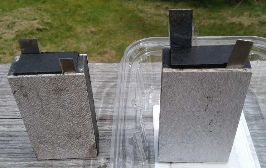
new small cell (in an old ABS plastic case with a
new,
better fitting lid) with fresh (KOH) electrolyte. Again I used [some
other] chunks
of the "D" cell for the nickel oxides side, with a piece of
cupro-nickel sheet as a current collector plate. I painted the osmium
doped
film on the zinc with a small brush.
I
made
a
new small cell (in an old ABS plastic case with a
new,
better fitting lid) with fresh (KOH) electrolyte. Again I used [some
other] chunks
of the "D" cell for the nickel oxides side, with a piece of
cupro-nickel sheet as a current collector plate. I painted the osmium
doped
film on the zinc with a small brush.
The cell worked! And it had very good current for the size
of the electrodes. So either the coating worked great, or it had
dissolved in the caustic alkali. Furthermore the self discharge was
quite low -
probably the good fitting lid was keeping fresh oxygen out.
Next the
question was what would the cycle life be? Would the zinc grow
dendrites and short the cell as usual, or did the film keep it out of
the electrolyte entirely?
Seven charge-discharge cycles worked without dendrites
shorting the cell. That was more than I ever got before. After the
fifth and eighth charge I opened the cell and inspected the separator
grill and the zinc electrode under a microscope. No dendrites! And the
cell continued to work.
It looked like a winner! And after all these years and all this
research, the
only thing different from so many other short-lived or relatively short
lived nickel-zinc cells was the coating on the zinc - which I had
formulated a decade ago but not put to its best use! I may still
experiment occasionally with milder electrolyte and different metals.
There may be a number of things that will work well. But even if
nothing comes of anything else I try, this seemed to be an excellent
cell!
But the zinc, while not forming dendrites, still degraded.
Eventually the first one disintegrated at the water line. Next will be
figuring out what to use to jell the zinc electrode to prevent that, to
make it "permanent".
I took many pictures of the several surfaces under the
microscope during making, before use, and after being used, to the
point that when I came to use them, I had lost track of what many of
them were.
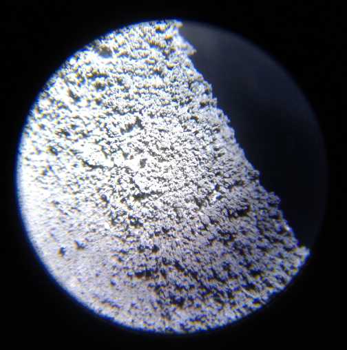
A "fluffy" electroplating of porous zinc on the
zinc electrode to give it
more substance and surface area came out much thicker near the edges
than in the middle, so improvements are needed to the plating process.
Once the design - every aspect of each component of the
cell - is optimized, fast and automated manufacturing techniques and
production will become the main focus.
But in spite of the progress, somewhere heading toward the
end of the month I must have "burned out" on chemistry & materials
sciences. I did some studying, but didn't get any more actual work
done.
Misc
Of course one continually learns more about topics
previously mentioned. I wondered in a recent issue why it seemed to
take more energy to recharge the car than the indicator said it had
used. One reason: it was mentioned in a video that recharging a car
with a lithium battery is only 90 even down to 80 % efficient. Lower
charge
efficiency would account for a good share of the discrepancy.
---
There was something odd with the solar panel system I had
put in for the off-grid lady across the road, which was supposed to
have been finished in May. When I first tried it, the 1500 watt
inverter had run her 1000 watt 'shop vac' vacuum cleaner. Then it
wouldn't. I attributed it to the initial overcharging of the 'frame 27'
lead acid battery I had given her (owing to the charge controller
unexpectedly being "positive ground"). I finally brought over a four
100 amp-hour lithium cells battery, a spare from the old Suzuki Swift
EV. It still wouldn't run! It was all the same: turn it on and after
about 2 seconds the low voltage alarm would go off on the inverter. In
a couple more seconds the 100 amp breaker I had put in for safety would
blow. I realized the #10 wires I had used, tho quite short (2 feet),
were pretty light for such a heavy load and replaced them with #6. No
change! I finally thought: it worked the first day.... what?... until I
had installed the safety breaker. I took it out and taped the wires
together. Sure enough, it worked fine! The 100 amp circuit breaker
itself was
high resistance. I found the in-line battery fuse from the old Mazda
RX7-EV and installed it where the breaker had been, and sold her the
spare lithium battery, which would doubtless run the vacuum cleaner
longer in a session, and last longer in years, than
the old "27" lead-acid. (notwithstanding that I had put sodium sulfate
in the "27" in 2016 to make it last longer. I got it as a scrap battery
about 4 years ago and it's still fine.)
---
Toward the end of the month, on the 24th, I returned to
milling my spruce after neglecting it all winter and spring when it was
cold and
the days were short. I had purchased an Alaska mill off Amazon for my
big chainsaw. (one might say belatedly - previously I had borrowed
one.) After much assembly, setup and chainsaw issues (putting on the
very
dull chain that had hit a screw... on backward at first, a terminally
dull chain sharpening file, mixing gasoline...) I sliced into one of
the smaller logs now lying there almost two years and made a couple of
slabs. It was hot, loud, stinky and exhausting. I had to repeatedly
stop to step back and breathe some clean air. Oh well, just a few
chainsaw cuts to make it into big cants, and then I could use the fine
electric handheld bandmill I had invented last year [TE News issues of
2018] to make lumber. It made eleven 12 foot 2"x6"s and one 2-1/2"
thick slab.
As I worked, woodbugs and termites and millipedes were
trying to find
new places to get back under the bark. The wood was spalted. And it had
cracks (but they were likely formed when it was felled). Yes, it was
high time to get the rest of the spruce milled up. Another winter and
it might not be worth milling.
---
Wiring the
HAT35V-50A Ceramic socket
 I could see the
ground effect vehicle, sitting there
waiting
all month, wasn't going to get its wing in June! And I fired the
ceramic HAT36V-50A socket in the kiln and wired it, but I hadn't even
made
the HAT36V-50A plug to plug the kitchen water tank into it.
I could see the
ground effect vehicle, sitting there
waiting
all month, wasn't going to get its wing in June! And I fired the
ceramic HAT36V-50A socket in the kiln and wired it, but I hadn't even
made
the HAT36V-50A plug to plug the kitchen water tank into it.
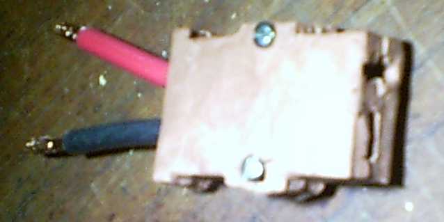
(Shoulduna used that camera for a close-up!)
The idea of putting up more solar panels remained just an
idea even tho I had the panels. I became aware of some obscure but
important safety considerations about HE ray energy and set that aside
while I consider whether or how to continue. Still, successful new
chemistry battery results atone for much lack of progress in other
areas.
But in a late night work session on the 27th I at least
cut foam ribs for the 'GEV's wing. (At the back they end where the
steerable elevator flap begins.) And the powerful 90mm ducted fans
("electric jets") had arrived - but not the "ESC" motor controllers for
them.
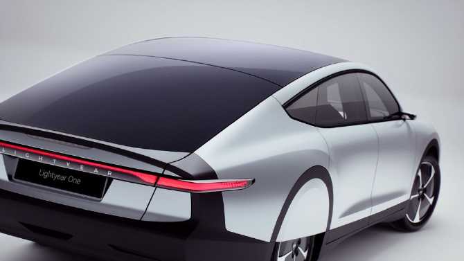
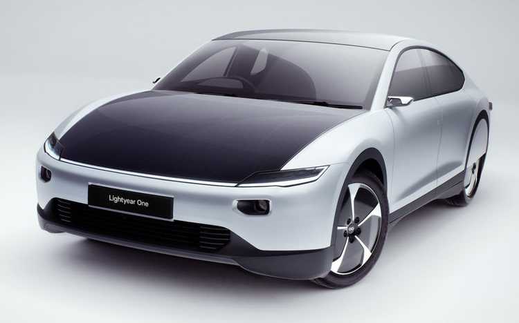
Beaten to an "Ultra Efficient" Electric Car! - the Lightyear One
 On
youtube
and
in
news articles on the web I found the "Lightyear One",
a Dutch prototype for an ultra-efficient (their term as well as mine)
production vehicle complete with built-in solar panels, by the same
team that had won the cross-Australia solar powered car race a few
years ago against some big-name competition ("Honda" was mentioned). In
the video it went for its very first low speed drive. I saw them
pushing it backward - maybe like my Sprint in its current configuration
it doesn't back up yet!
On
youtube
and
in
news articles on the web I found the "Lightyear One",
a Dutch prototype for an ultra-efficient (their term as well as mine)
production vehicle complete with built-in solar panels, by the same
team that had won the cross-Australia solar powered car race a few
years ago against some big-name competition ("Honda" was mentioned). In
the video it went for its very first low speed drive. I saw them
pushing it backward - maybe like my Sprint in its current configuration
it doesn't back up yet!
It is expected to use 2/3 of the energy of a Tesla (or
Leaf, etc.) to go the same distance - a similar figure to what I was
trying to achieve for in-town driving. A big difference was that theirs
was designed and made with the efficiency goal in mind from the ground
up, whereas I simply had a car conversion in mind. They built it light,
incorporated the best solar cells right into the roof, hood and
hatchback, and made it extremely low wind drag. (As good as the GM
EV-1?) So its highway efficiency would no doubt be highest, and
doubtless better than a conversion could achieve. (But the Sprint was
pretty much the lightest mass-produced car, and not so much wind drag
either. I wonder if the original Suzuki equipment for manufacturing the
Swifts/Sprints/Fireflys is all rotting in some junk yard(s) somewhere?
But I suppose resurrecting that assembly line is a ridiculous idea!)
Perhaps I should just admit someone has (at long last)
beat me to it and give up. OTOH it's a prototype and they may not get
it into production. If they do it will be a very costly car. I couldn't
find
any info on the four in-wheel motors, but somehow it got me thinking
about ultra-efficient motors, controllers and transmissions again for a
few days. On July 1st I came up with inspirations for better solutions
for both unipolar BLDC motors and variable transmissions. They must
have been long festering in my subconscious mind to both pop up like
that on the same day!
Bonnet, lid and liftback
are all solar panels, all cells
independently contributing even if others are in shade.
(1.5 KW total solar? IIRC)
Solar on a car using many thousands of watts may sound almost trivial,
but it's always
charging and the makers estimate as high as 10,000 to 20,000 kilometers
free travel per year
owing to the solar recharging. (the higher figure is if you live
in a cloudless desert at lower latitude)
 I suspect money helps get the layout and
cosmetic details looked after.
I suspect money helps get the layout and
cosmetic details looked after.
(What must all these custom components have cost?)
Unipolar BLDC Motor Concept
 Any lingering thoughts of maybe getting the
newsletter out on Canada Day (July 1st) were dashed when that morning I
got to the "Unipolar BLDC Motors" idea section (Electric Transport,
below),
and
started
realizing
exciting new possibilities and exploring
them "on paper" as it were.
Any lingering thoughts of maybe getting the
newsletter out on Canada Day (July 1st) were dashed when that morning I
got to the "Unipolar BLDC Motors" idea section (Electric Transport,
below),
and
started
realizing
exciting new possibilities and exploring
them "on paper" as it were.
I hadn't been able to work out a unipolar magnet rotor and
stator design that would work properly before, but now I discovered
that if one went from "typical" 3-phase motor design to more phases and
activating coils individually instead of in pairs on opposite sides of
the stator, certain configurations appeared to work. If one could be
made to work well, it should be worth doing. Of course a custom motor
controller would be required too.
Even if I still came up with nothing I could manage to
build for a variable
transmission, with two such motors of maybe 8, 10 or 12 coils, each
driving one front wheel, together they would probably have enough
torque for fixed 3 to 1 ratio chains, belts or gears, allowing both
sufficient startup torque and highway speeds at safe motor RPM.s.
Perhaps that would be at least as worthy of pursuit as the
reluctance motor, given the "ultra-efficiency" of BLDC motors and their
high mechanical tolerance for small dimensional variations. And I've
already made good BLDC motors and controllers that at least work.
Variable Transmission Concept
Then toward evening (still July 1st) inspiration struck
for a better
variable transmission, too. This torque converter would combine two
previously used components: the planetary gear and the centrifugal
clutch.
What the planetary gear - or any variable ratio coupling
component - lacked was a means to control the third "control" element
to variably change the ratio between the other two elements coupling
the motor (ring gear) to the wheels (planets assembly). (That was where
I had tried using a rope around a large pulley. That wasted energy. But
it worked with a flywheel to transfer revved up motor energy into car
motion and get the car moving.)
A centrifugal clutch unit such as I had already made could
provide the means to control the control element: the faster the motor
(and centrifugal shoes) turned, the more stongly the centrifugal drum
would want to turn with the motor rather than just turn opposite to it.
By having the control element be the one that spun fastest with the
least torque (sun gear), the forces to slow the drum would be
maximized, which would provide highest torque to turn the output
element with the least torque on the drum.
Free spinning with the car stopped, the centrifugal outer
drum on the sun gear would turn around twice as fast as the motor
turned the ring gear with the centrifugal shoes on it. And it would
take 1/2 the torque to slow or stop it. (Ratio depending on the actual
planetary gear chosen.) So if the motor with the centrifugal shoes
turned 1500-2500 RPM, the drum if it was free-spinning would turn
3000-5000 RPM in the opposite direction, and the output gear wouldn't
move. But hopefully somewhere in that range we're looking at
speeds that will sufficiently engage the centrifugal coupling. As the
shoes engage the outer rim, the set would have a very large tendency to
want to slow the drum, which will turn the planets assembly and drive
the car ahead, slowly at first with highest torque and then graudally
increased speed and reduced torque.
While the ratio of the input (ring) to output (planets)
with the sun gear (drum) held stopped might be 1.5 to 1, the sun gear
goes from freely spinning before the centrifuge engages, to being
loacked and turning with the shoes and so all three gears turn in
unison, 1 to 1.
On the other hand (July 3rd - I'm trying to finish up the newsletter
but I can't stop thinking about it!)... a better way to do it would be
to have the motor drive the planet gears assembly, with the output on
the ring gear instead of the other way around. The centrifugal clutch
drum is still on the sun gear. That way, with the car (ring gear)
stopped, the drum wants to speed up to 3 times the motor speed instead
of 2 times, with only 1/3 as much torque required to bring it down to
motor speed. More importantly the drum also spins in the same
direction as the motor. That means that as the centrifugal shoes
contact the drum to slow it down, the rotating force tries to make the
motor speed up instead of slow down. The inertia of the spinning drum
works for us instead of against us. This is something I have been
trying to figure out how to achieve since 2012 too.
In theory if the drum were stopped the output/ring
gear/car would go backward at 1.5 times the speed of the motor. In
fact, the drum will never go slower than the motor, when it is fully
locked to it, and all three gears will turn in 1 to 1 unison as before.
Another possibility is to use, say, an idler wheel and a
belt between the ring gear (motor) and sun gear (control element).
Pulling the idler wheel tighter couples the two more strongly, so the
driver would have a stick clutch or something to do that. (That's close
to something I tried before, but applied a little differently.)
So there it is! The two components together, the planetary
gear to allow
variable ratios and the centrifugal (or other) clutch as the ratio
control
element, should make a fine variable torque converter. It seems it has
taken me a decade to figure this one out, too. I started on a variable
torque converter in spring 2009. This one should be more satisfactory
than any previous idea.
The variable reduction output would feed a further fixed
reduction to the differential, eg, 3 to 1, to drive the wheels.
---
I am now impinging on July, so it's time to wrap it up!
I'll call it June 31st, 32nd and 33rd. (Hah! - that means I got more
vegetables planted by
the end of June after all.) (January to June only has 181 days anyway,
while
July to December has 184. Like so many things on this planet,
the calendar isn't the first or last that 'just grew', piecemeal,
instead of being logically designed.)
Early June Diary: where does my time go?
1st to 3rd - Add photos/edit/finish up of TE News #132, and wrapping up
the solar installation across the road.
4th ??? Some other writing...???
5th - Another disappointing new chemie battery experiment.
6th - Fixed lawn tractor. It broke down at the far end of the field and
wouldn't move. I had to try and see what to do underneath in 15" grass,
then took a trip to town for the part. (Gasp! They had it in stock!)
7th - Writing up an article for Haida Gwaii Trader magazine for
July-August issue. (I said I'd do one every 2 months. It didn't seem
onerous when I volunteered. -- The last one was an update on the
completed Handheld Bandsaw Mill. Two others have been on aspects of
Planetary Management/Social sustainability.)
8th - Picked up the new crate of 305 watt solar panels in two trips to
Masset - 4 hours just driving. Car and trailer were heavily loaded to
bring 16 each time.
9th - Someone phoned me before I was out of bed and yakked for almost 2
hours. I planted all the asparagus I wanted, then phoned someone to see
if they wanted more of the plants. They invited me to see their
shop-building project and then dinner. Well it was Sunday anyway!
10th - Finally I just HAD to put an ad in the Trader for solar stuff.
Why else had I brought solar panels et al up to this island and then
designed the HAT36V wiring and other infrastructure stuff? Well, I had
too much to fit in a
classified ad so I had to update the price list and make it HTML and
put it on my web site. The link
TurquoiseEnergy.com/SolarStuffPriceList.html only took me to the site,
not to the page. So I had to make a link from the main page menu. The
main page was way out of date so I spent some time editing that. Wrote
up two years "null" tax returns for Turquoise Energy Ltd. I haven't got
any R & D money
out of them since 2015 anyway. Nap time. But in the evening I finally
fixed
my mini kiln. (For once, a job that proved to be easy and went
smoothly!) Then I fired the ceramic HAT36V-50A socket.
11th - Made copper spring pins and wired the socket with short #8
wires. (But I didn't get to doing a plug.)
[12th - enough of this!]
In Passing
(Miscellaneous topics, editorial comments & opinionated rants)
World Unity
In times past,
transportation and communication were such that mainly it was close
neighbors that interacted, in trade and war. Even in 1700 it took over
a week to get from London to Scotland by horse carriage. Egyptian,
Greek and Roman civilizations centered around the Mediterranean Sea
because boat travel was better than land travel. These peoples
conquered those around them to exploit the resources and make slaves of
the conquered lands. There was no thought of the conquered people
having a culture and society that might have value which was being
destroyed, or that the people
there were spiritually equal with those who managed to conquer them.
Later mostly Europeans set sail in ships and conquered
around the world to exploit and enslave, to make an empire. The British
empire sought also to educate and left their forms of law and
government behind, but the primary motivation was still domination and
economic advantage. If there was to be unity, it was by the conquered
being forcibly united with the conquerors.
In the last 500 years the world has been entirely occupied
and settled. The attempts of one culture to dominate other more or less
equal cultures was rife throughout Europe and later North America over
the last millennium or so. Mostly little consideration was given to the
conquered. Then ending only a decade before I was born, the whole world
passed through the tremendous convulsion of world war two, a clash of
wills between several ideologies embodying mostly domination and
enslavement of peoples - starting with one's own country's peoples.
When I was young, countries were still much more separate
and
culturally isolated from one another. The so-called "United Nations"
had been formed, but "the international community" wasn't a part of
speech and
no one spoke much of "international law". Besides Europe, other
continents
were mystical
far-off lands that were (surely) of little concern to us in North
America.
"We all drink the
same water. We all breathe the same air." - John F. Kennedy
Trade and commerce started to change the world. Suddenly
everyone everywhere wanted to learn English as a means to be able to
communicate worldwide, to do business and open up their markets. I'm
not extolling English for its own sake, but it was the first
time everyone had, implicitly, agreed on one particular language as the
means to enable
international communication. Strange people speaking strange tongues
were suddenly no longer so strange or mysterious when they spoke in
your language, or at least one you too had learned.
We are politically separate, but through extensive trade
the world has largely become one economy. While we will retain our
cultural and racial identities for ages, the world will continue to
become more and more equal, more and more "all one people" as
international and intercontinental relationships are viewed. Wars,
refugee migrations and the fierceness of competition will be in the
past when the population has dropped (and is thereafter managed to
maintain stability) and there is material prosperity for everyone.
Witch
Hazel
&
Red
Spots
I had been been getting red spots on my upper legs for
some
time, which were proving intractable/chronic. They seem to be some kind
of mite - perhaps house dust mites? probably not even a millimeter
long. I have stabbed some with a needle and the spot goes away, but
more often I stab myself. I don't recommend it. I have recognized for
some time that they occur when something is pressed hard against my
leg, as in carrying in a pail of firewood or crossing my legs and one
is pressed against the underside of the desk. The area pressed is
exactly where
they occur. Apparently they can't penetrate the skin unless helped. But
then they seem to spread.
Antibiotic cream sort of helped. Daily baths sort of
helped. The witch hazel, applied lightly (hard rub bad), got rid of
them. And if a new spot should appear, a drop of it gets rid of it. And
Wikipedia says there's no proven medical use for witch hazel. Hah!
"Rivers
from
the
Sky"?
Here are a couple of good photos I ran across in a video,
showing what is said to be the "rivers from the sky" rainfall that has
never been seen until these last few years, which are now causing such
devastating flash flooding around the world.
To see each week or two's growing crescendo of calamities
from all around the world, go to "World of Signs" and "Nared King".
 Calgary, Alberta
 Mexico
ESD
(Eccentric Silliness Department)
* I searched on eggwhite as something to put on burns, having heard of
it
and noticed that it wasn't mentioned in the Wikipedia article on
albumen. There were some hits where it was obvious that
it wasn't wholly in favor in the medical community. A lady on youtube
said,
with reasonable arguments, that it was an urban myth and that eggwhite
was no good for burns - and it might cause a salmonella infection.
But there were exactly 21 comments under the
video, 17 from people who had used it on various burns mild to
severe including
sunburn that said she didn't know what she was
talking about, that there was nothing better for burns than eggwhite.
Not one of the commenters supported her. One person said eggwhite has
the amino acids glycine and proline and that these give the body the
building blocks to build collagen when eaten, and that it seemed to
work well applied on burns too.
* The issue reminds me of "planting by the phases of the moon." This
doesn't fit with scientists' narrow logic, so they are quick to call it
"superstition". But apparently any farmers' almanac discloses that
there is statistically more rainfall at certain phases of the moon than
between them. (IIRC it was more around full moon and new moon.) The
moon makes atmospheric tides as well as oceanic. Depending on climate,
if you don't have running water for the crop or "anytime" irrigation it
could be important or at least helpful to plant according to the phases
of the moon.
* They say there's such a thing as "50-50" chance. When I open my
microwave oven door, the coffee cup handle is almost invariably rotated
around the back somewhere. It's been that way at least for a year or
two. But the last couple of weeks sometimes it's been at the front or
at the side. That's really spooky to find the coffee cup handle at the
front when I open the door! (Is the rotator platter in my microwave
wearing out? or am I just selecting the right amounts of time sometimes
now, instead of invariably the wrong lengths?)
* A store owner tries to guess what to order that he hopes his
customers will want to buy. With some items it's like throwing a dice -
people may buy lots, or none at all. That's why it's called
"merchantdice".
* People have said that the last living relative of the dinosaurs is
the tuatara of New Zealand. But they forgot the Thesaurus. Oh, wait...
that's probably extinct now, too.
* Something with four square corners is a rectangle. If one side gets
shoved too hard the corners buckle and it becomes four wrecked angles.
* Crazy English spelling conventions yield a seafood favorite: everyone
loves ghoti! ("gh" as in "enough", "o" as in "women", "ti" as in
"vacation")
* Nilliamps: current flows too small to measure.
"in depth reports" for
each project are below. I hope they may be useful to anyone who wants
to get into a similar project, to glean ideas for how something
might be done, as well as things that might have been tried or thought
of... and even of how not to do something - why it didn't
work or proved impractical. Sometimes they set out inventive thoughts
almost as they occur - and are the actual organization and elaboration
in writing of those thoughts. They are thus partly a diary and are not
extensively proof-read for literary perfection and consistency before
publication. I hope they add to the body of wisdom for other
researchers and developers to help them find more productive paths and
avoid potential pitfalls and dead ends.
(Note: Don't miss the Solar Car Charging
Trailer under Electricity Generation!)
Ground
Effect
Vehicle
(first
the
R/C
Model)
I didn't get much done on
it, but the 90mm ducted
fans arrived early in the month, and I did cut some styrene foam ribs
for the wing late at night on the 27th.
A control problem occurs to me: the "ESC" motor controller
I
have presently seems to have no control to put it into reverse and I
expect I'll be very lucky if the new ones (where are they?) have
reverse either. And the radio control also has no control for
reversing, much less for reversing two motors separately. By using the
"elevator" control it could thrust two motors separately. Then how do I
control the elevator? With the "ailerons" control?
It will be very tricky docking if one can't reverse the
thrusts. I'll have to either make some elaborate on-board electronics
or
accept that the RC model will have some aggravating limitations - all
in the
control system.
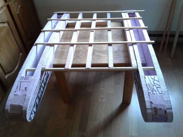 The ribs for the wing
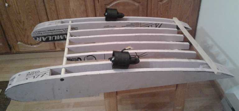 The left-and-right ducted fan "electric jet"
motors will mount just above,
The left-and-right ducted fan "electric jet"
motors will mount just above,
and may shrink (or replace?) the "dorsal fin" rudder idea.
The elevator goes behind the wing to almost the back of the hulls.
One might say the wing profile will be somewhat akin to a plane with
its "flaps
down".
More
Unipolar
BLDC
Motor
Ideas
I was closing windows on the computer screen when I ran
across
TurquoiseEnergy.com from editing it last month. The Electric Hubcap
motors were of course there, with the word "unipolar". I see a definite
advantage of unipolar as being reliability: there is no path
from B+ to B- except through a coil. Spurious turn-on of the wrong
transistor can't create a short circuit and blow up the controller. If
the permanent magnet assist idea works, reduces energy consumption,
then that will also be a major advantage. So far I have been unable to
test out that feature in a motor.
Unipolar coils can work easily for a reluctance motor
because
magnetic polarity doesn't matter - either the rotor metal is attracted
or it isn't.
But I thought
about how I had been unable to figure out a BLDC rotor magnet
& coil configuration that would actually work. There had to be
north and south
poles on the rotor and in the stator for good magnetic circuits, or the
thrust was much reduced.
Then, any arrangement seemed to reverse the drive half way around the
rotation. One would have to reverse the polarity of the drive to finish
the circle. Then it wouldn't be "unipolar".
But that was with turning on coils in pairs, one north and
one south, across the diameter of the motor, and using typical 3
phase power.
Out of the blue I thought I had an inspiration. By the
time I had drawn it all out and figured out how it would work, it
required a different and more complex operation of the coils, and very
specific numbers of coils and magnets, not the usual 3-to-2 of 3-phase
motors. But it
could use the regular Electric Caik motor. That would mean I
wouldn't have to make a new motor to try it out - just change the
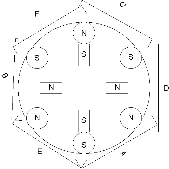
wiring in the Electric Caik and connect the unipolar motor controller. Instead of activating pairs of coils across
the motor from each other, each of the 6 coils
would be separately actuated. Half the motor would still have reverse
thrust at any given rotor rotation, but that half wouldn't be activated.
They wouldn't be actuated in fixed "pairs", but in
rotating pairs. Only two coils would be on at a
time. Thus to rotate clockwise, the coil pair activation sequence would
be: B, E, A, D, C, F - counter-rotating compared to the rotor.
"Electric Caik" version
But an 8 coil, 6 magnet "Electric Hubcap" size motor would
probably be a more valuable unit. It would have more power and torque,
and instead of only two coils on at a time, it could have three or four
- up to half of them - to further increase the torque.
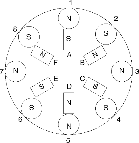 8 coil, 6 magnet "Electric Hubcap" size version.
To rotate, individual coils are activated [always in pairs for magnetic
equality?]
Start: 6 & 7 are activated. If more torque is needed, 5 & 8 are
activated.
When magnet F reaches coil 8: coils 5 & 6; add 4 & 7 for more
torque.
Then 4 & 5, then 3 & 4, then 2 & 3...
But the 6 coil, 4 magnet, version looks like it should
work for a full rotation. That gives me hope that there must be
other workable combinations too. Obviously there must be an even
number of magnets on the rotor and an even number of coils on the
stator to avoid two in a row of like polarity. It looks like if the
magnets are N-S on opposite sides of the rotor, the coils opposite must
be N-N, or vice versa. I need to think further on that! Apparently it's
trickier
than it looks. I think I need to cut out a paper rotor and actually
turn it in a paper stator for each set of coils and magnets, to
properly plot out coil activation sequences.
With unipolar coils, one can try out the promising
"permanent magnetic assist" idea (in some 2016(?) issues of TE News).
There just might be some 'free energy' to be had in that!
Jim
Harrington's
Latest
Electric
Outboard
Motor
Jim sold his previous electric outboard and has
made/converted a new one. (3 HP IIRC) It is again a 3-phase induction
motor with variable frequency drive, running off 36 volts of batteries.
He says he ordered the components including the motor from China and
they cost far less. He isn't making innovative motors, controllers and
new chemistry batteries, but unlike mine his projects get done
and work in good time!
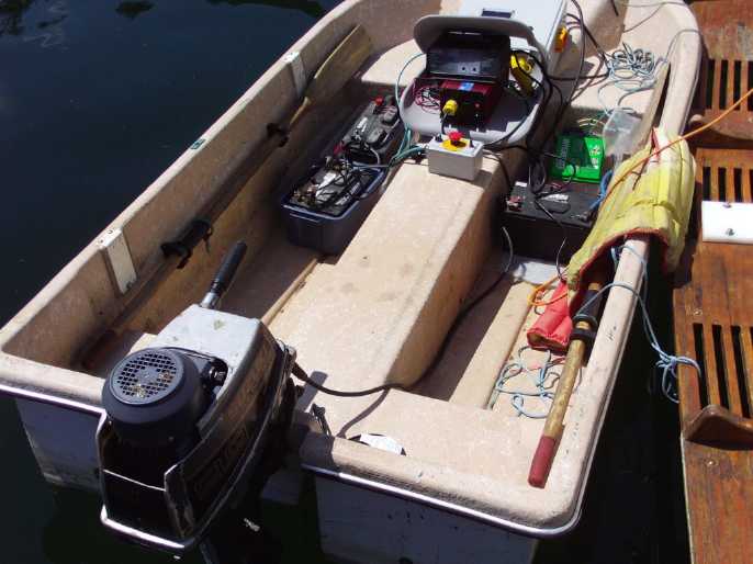
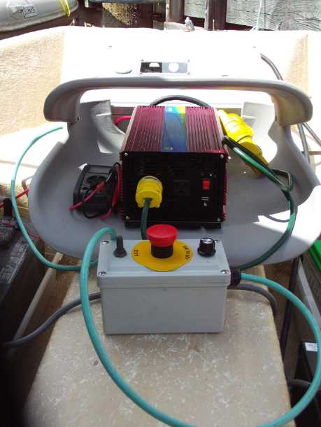 36 VDC to 240 VAC Inverter, and controls
Other
"Green"
Electric
Equipment
Projects
36
V
DC
"Off
Grid"
Infrastructure
HAT36V-50A Ceramic Sockets
On the evening of the 10th I repaired my mini
kiln and
then fired the two clay socket
halves to 'cone 05', which my scribbled piece of paper said was the
temperature the kiln reaches after 75 minutes, after which time I
unplugged it. The red clay looked the same after firing as before, but
it had that ceramic "clink" to it when the pieces touched together.
Then I went hunting all over for the plug, on a long black cable. How
do I keep misplacing things? In this case the cable had kept me from
putting it in the "HAT36V" drawer and I found it draped over a chair in
the workshop. Somewhat to my amazement, it had shrunk to virtually the
ideal size in drying and then firing. (I had scaled the mold something
like 18% oversize - apparently a good guess... for this clay, at this
stiffness, at this firing temperature. I hope it's duplicatable.)
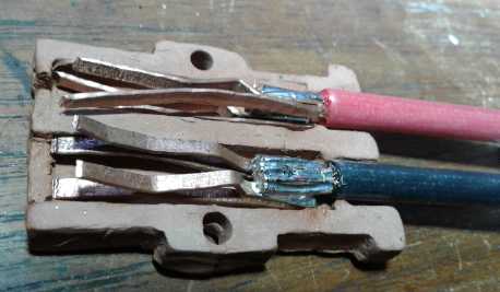
The next morning I made the "hairpins" and attached two
short "pigtail" wires. The plug seemed to fit pretty snugly.
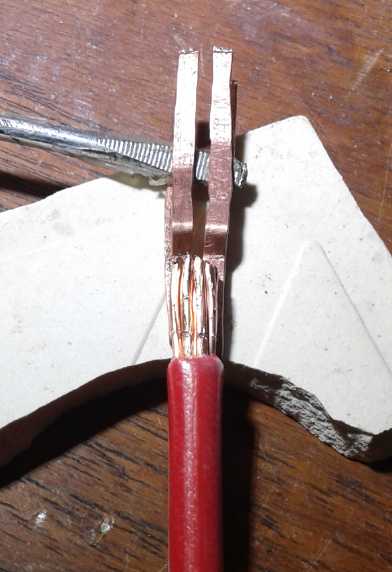 How to hold the two 'hairpins' in line while
soldering the wire on?
How to hold the two 'hairpins' in line while
soldering the wire on?
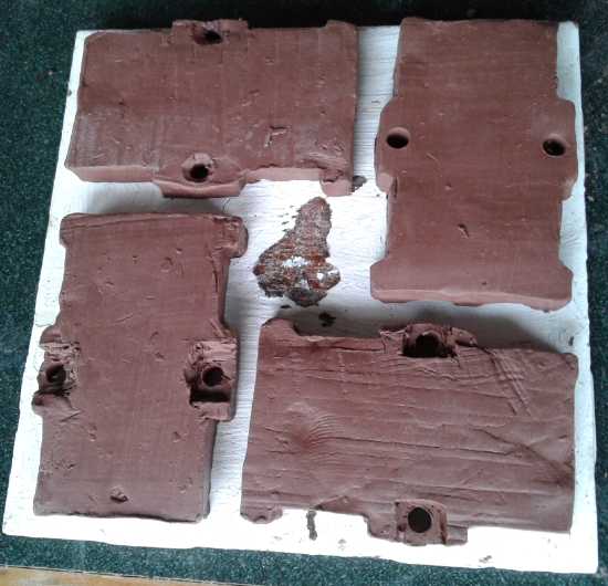
Since it worked, I molded two more. I may
do a couple more yet before I fire them.
(My only #4-40 bolts are a bit too short, 1/2"
so I made the square indents.)
Another small 36 V solar water heater
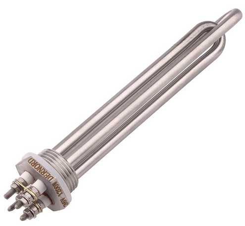 An off-grid friend had bought some of my 305
watt solar
panels. I saw he had connected one straight to a ~15 liter hot water
tank that had come out of a travel trailer, now lying loose. I knew
from my own experiment that he wouldn't heat water very fast with a 120
volt
heating element with a panel under 40 volts. My next two Dernord 36
volt water heater elements arrived on May 31st and I took them to his
place on June 2nd. It turned out the 1 inch thread model fit his tank.
With considerable difficulty we (he) got the rustic old element out and
we put the new one in. (rustic = rust; ick!) I should have checked the
resistance/power of the old element. It didn't occur to me. It probably
wasn't even 1000 watts.
An off-grid friend had bought some of my 305
watt solar
panels. I saw he had connected one straight to a ~15 liter hot water
tank that had come out of a travel trailer, now lying loose. I knew
from my own experiment that he wouldn't heat water very fast with a 120
volt
heating element with a panel under 40 volts. My next two Dernord 36
volt water heater elements arrived on May 31st and I took them to his
place on June 2nd. It turned out the 1 inch thread model fit his tank.
With considerable difficulty we (he) got the rustic old element out and
we put the new one in. (rustic = rust; ick!) I should have checked the
resistance/power of the old element. It didn't occur to me. It probably
wasn't even 1000 watts.
He filled the tank from a hose and we hooked it up. There
was just one problem: it was raining and there was virtually no solar
power to be had. When we've had some sunny weather and I get a chance
to go up there again, I'll see how that's faring. (As of the 14th,
still not one nice sunny day.)
Near the end of the month I saw him and asked. He said it
gets "pretty warm". I guess for "really hot", especially on cloudy
days, one would want two solar panels instead of just the one he has
connected (which isn't well aimed, either - almost vertical against a
westerly wall, held in place with a rope).
Rong Inverter? ...Hmm, No!
I had got a 2500 watt, 36 volt to 230 volt inverter to run
my well pump if the power was off. I decided to order a similar 36 to
120 volt one to have one for the fridge and another (I already have)
for the freezer. It
arrived on the 10th but when I took it out of the box, it looked like
another 36 volt to 230 volt one! What to do... send it back? keep it to
sell? and then, order another one?
The next day I looked at the label on the bottom to see if
anything said the input was 36 volts. The tag had everything with boxes
to tick off.
The numbers ticked off were 36 VDC, 120 VAC, 60 Hz, 2500 watts. Huh?
120 volts with a 230 volt socket? Did I need to make an adapter?
I looked at the rather odd socket again and discovered it
was cleverly made with extra slots so you could plug either a 120 or a
230 volt plug into it! It had pins for both! Wow! That defeats the
whole purpose of having different plugs for different voltages! Perhaps
only the Chinese would dare do that! (I've seen another such plug
since, also on a unit Made in China.) I could plug a 120 volt appliance
into the 230 volt inverter or vice versa - especially as they were
identical on the outside except for the tick marks on the tiny label on
the bottom. The
top said simply "Power Inverter / 2500 Watts / Pure Sine Wave". That
applied to every model. (I wondered if the components inside were
actually different or if one merely changed jumper wires - or even just
programming - for the
different specs. But for that much power one suspects they'd have
different spec power transistors, capacitors, and a couple of other
components for
the different input and output
voltages. The rest might well be the same.)
I took a felt pen and printed "120 V" on the one and "230
V" on the other on top near the socket end. And "36 V" near the input
end of both for good measure. Now you can only get it rong if you space
out. The trick will be to mount the 230 V one near the well pump plug.
(Yet to be installed.) Then the position will indicate what it's for.
It seems to me the manufacturer could fix the socket
pretty easily by inserting one of two plastic plugs, flat on the
outside, that would
plug in and block the wrong holes so that only the right plug would
fit.
That could be easily defeated by removing it, but why would one do so?
Laser
Engraver
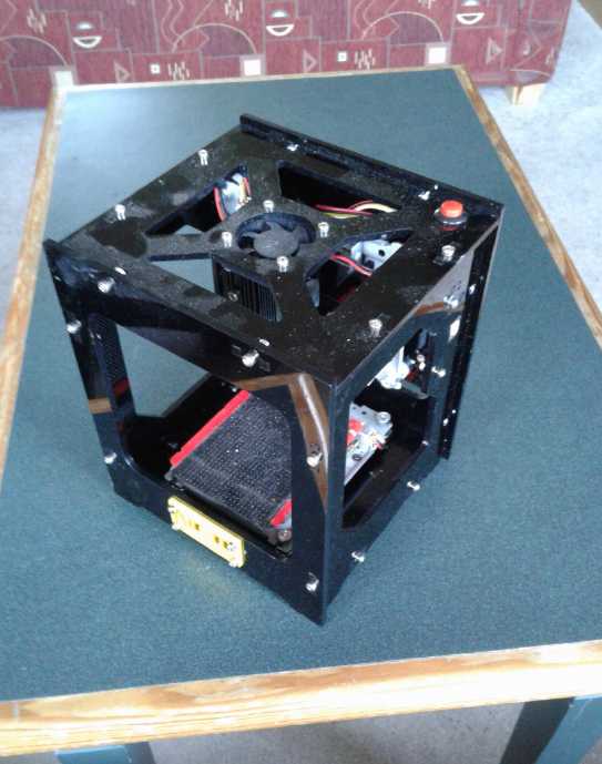 I was given a very small laser
engraver. (NEJE model DK-8-KZ) The owner couldn't get it to work for him. It specifically
prints black and white images (no grays) of size 520x520 pixels, at 350
pixels per inch. Each pixel is either burned or not burned. Burn time
for each pixel can be set from 0 to 230 - I think that's milliseconds.
I was given a very small laser
engraver. (NEJE model DK-8-KZ) The owner couldn't get it to work for him. It specifically
prints black and white images (no grays) of size 520x520 pixels, at 350
pixels per inch. Each pixel is either burned or not burned. Burn time
for each pixel can be set from 0 to 230 - I think that's milliseconds.
I understand the size is because it's made with obsolete
hard drive stepper motor systems. Clever to find such a cool new use
for them instead of the garbage can!
I spent much of the 20th and got a computer set up to run
it. (Why are these things never simple?) I recall that once upon a time
I got laser
diodes and was going to set up my CNC machine to burn holes to
perforate plastic for plastic pocket battery electrodes. I never got it
set up. This might do that job if I ever want it done.
The only present use I can see for this machine is to
engrave labels onto things like my HAT series plugs and sockets. (and
it doesn't seem to work on white ABS.) Perhaps something more in
keeping with its suitabilities will come along.
Someone on youtube said
he tried painting a printed circuit board with (?)black nail polish(?)
and burning it off the parts of the board that were to be etched. It
wasn't successful, but he hadn't yet tried a longer burn time or going
over it twice or more, which (looking at his board) just might
make the difference. (I wonder what other coating might work. Black
spray paint?) It might be a cool technique, but the board size would be
quite limited. 520 pixels at 350 pixels per inch is only about 1.5
inches square.
I view this software
installation as practice for getting the ANYCUBIC I3 MEGA 3D
printer software working as well as the GECKODRIVE CNC Table
Stepper Motor Driver. So many things to do!
Solar
Car
Charging
Trailer
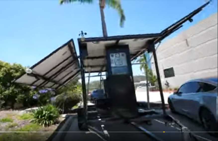 Jehu Garcia is a solar and EV buff who
reports everything
he sees and does
to Youtube. He has a LOT of videos. He went to the 2019 EVWest EV show
and found a trailer with fifteen big 72-cell solar panels, batteries,
charging system electronics, a wind sensor and a sun tracker. The panels are in 3 rows. The middle row of 5
panels is the roof of the trailer, fixed in position. The sides of the
trailer hinge up from the top to make the outer two rows. These track
the sun to unfold to the best angles. Sometime during the show it was
charging a car at 4.2 KW. It seems like a great system!
Jehu Garcia is a solar and EV buff who
reports everything
he sees and does
to Youtube. He has a LOT of videos. He went to the 2019 EVWest EV show
and found a trailer with fifteen big 72-cell solar panels, batteries,
charging system electronics, a wind sensor and a sun tracker. The panels are in 3 rows. The middle row of 5
panels is the roof of the trailer, fixed in position. The sides of the
trailer hinge up from the top to make the outer two rows. These track
the sun to unfold to the best angles. Sometime during the show it was
charging a car at 4.2 KW. It seems like a great system!
It's a pity commercial EVs have no facility to allow
charging while driving. Even the 5 roof panels might let a car drive
for free in city traffic.
From it I have the idea (a) to do something similar with
my utility trailer, or (b) to put three panels on top of my Chevy
Sprint instead of one, and have two of them unfold to the sides. The
downside would be that they probably couldn't charge the car while
driving, which I would arrange for with a single panel. Furthermore
there are lots of places one would be unable to unfold the panels. Then
again, many arrangements are possible both physically and electrically.
Perhaps it could charge with one panel while driving or parked without
room to deploy, and with all three when parked and unfolded. (I was
just going to have them facing up and not try for the solar tracking
either automatic or manual.)
Am I headed into "impractical" territory here?
My
Solar
Power
System
Observations of System Operation
On the 4th the rain stopped and the sun came out for a few minutes. Of
course the solar panels were still cold. I happened into the garage and
saw that the house panels alone (6 plus the 7th one on the lawn) were
making 1550 watts! Gotta love those cool panels. By the time I got to
the trailer to see what new record it might hold, the clouds had
returned. And that was it for sun for the day.
But the next morning it was sunny and well before noon the
trailer was putting out upwards of 940 watts. That's slightly above the
75% "realism factor" for 1220 rated watts of panels, and more than ever
before. The
maximum with one grid tie microinverter seemed to be 860-870, so
having two with two panels each was helping more than last month's few
readings would have indicated. It was at least 70 watts or 7.5% extra
and a 5 year payback on the second microinverter. Later it was
down to 915 - still more than before.
Another consideration besides simple electrical payback
math is that if the microinverters are more lightly loaded the thermal
stress will be less, so the cooling fans will run less often and they
may last longer. And if one does fail, the system is still putting out
lots of power. I don't think I'd put more than ~900 watts of solar
panels on one of these 1000 watt rated microinverters again. (I suppose
I should install the second one properly in the trailer. The freezer
can't be used with the open door and wires coming out of it!)
OTOH, if the majority of days are cloudy anyway as they
were in June, one microinverter or charge controller could run more
panels and have higher output without being pushed to its limits on all
those cloudy days.
Month of June Log of Solar Power Generated [and grid power consumed]
(All
times are in PST: clock 48 minutes ahead of sun.)
As I had been logging them, the power consuming activities
noted didn't always give an
indication of whether they occurred before or after a power meter
reading. On the 20th I got the idea to put them in the square brackets
with the power readings, before or after them. I backdated this to the
15th but didn't attempt to reorder the whole month.
Note: On the 7th I thought to start including the DC power as
well as that to the grid. DC power measured is that consumed - usually
under one kilowatt hour per day - mostly by the 36 volt kitchen
water heater with a bit by LED lights. The DC "power produced" reading
disappears when the sun
goes down and restarts the next day. I virtually never look at it at
right before dark, so I can't use it. I reset the "consumed" meter each
evening after reading it.
Note FWIW: On July 2nd I turned the battery charge controller
voltage down from 40.35 volts to 39.6 volts. That's 13.2 volts for each
12 volt section or 1.32 volts per cell. That's probably only about
80-85% charge, but it should be easy on the NiMH "D" dry cell
batteries.
One can float charge them as high as 42.0/14.0/1.40 volts, but
experience with them in the Mazda RX7-EV says not to push them so hard.
It's probably a reason some had dried out. (With 5000 watt-hours of
refurbished battery storage, under 1000 watt-hours from DC loads
doesn't draw them down too far. Long winter nights may need
conservation measures like turning the water heater off.)
Date House solar KWH(Grid+DC), Trailer Roof solar KWH - day
total KWH
made [power
co. meter readings] weather, usage...
May 31st 53.10, 393.27 - 5.26 KWH [66469 KWH @9:00, 485@20:30]
Lt.Rain. (no BR heat) 85 Km drv. fast charged.
June 1st 56.94, 397.18 - 7.75 [66502@20:30] cloudy, occasional sunny
spots in PM. 60 Km drv.Fast Chj.
2nd 58.56, 399.19 - 3.63 [66517@19:30] RAIN, more RAIN!
(We REALLY needed rain!) 49 Km Drv.- chjd.after meter reading.
The 4 older poly panels went to the DC system only, to keep kitchen hot
water hot, so real total might be ~4.4 KWH (with a little power going
to waste
from the 4 panels).
3rd 61.14, 401.68 - 5.07 [66537@20:30] Rain AM, cloudy PM.
55 Km Drv, fast Chj.
4th 64.08, 404.41 - 5.67 [66557@21:00] Rain, clouds.
5th 70.02, 409.40 - 10.93 [66570@24:00] Sun & clouds.
6th 75.29, 413.34 - 9.21 [66573@10:00, 581@21:00] Clouds,
Lt.clouds. 55Km drv.& fast chj.
7th 79.08+.60, 415.90 - 6.93 [66587@10:30, 592@20:30] Clouds. 55Km slow
chj.
8th 83.00+.65, 418.93 - 7.60 [66603@20:00] Cloudz.
9th 86.20+.42, 421.88 - 6.57 [66614@11:30 & 21:00] Cloudy, some
rain.
10th 88.10+.91, 424.04 - 4.97 [66637@21:00] Clouds, rain. Car part
chj.@1500W after 55Km. (Left BR heat on & door open, so it was
heating house - yowr!)
11th 92.27+.70, 427.57 - 9.40 [66643@13:30] Light Clouds &
chemtrails. Finished chj.car. Didn't turn off water heater for night.
12th 96.38+.50, 430.88 - 7.92 [66646@10:00; 66655@20:30] Lt.cloud AM,
Cloud rain PM. Bath AM; car slow chj. from 15:30-20:30 (How did the
water heater use LESS power by being left turned on all night? Ah...
the water isn't as hot. The top fell off the thermostat yesterday and
it must have turned the dial. I'm only turning it part way back up
because the water was really too hot - scalding.)
13th 98.86+.74, 433.28 - 5.62 [66661@20:00] Cloudy.
Finished slow
charging car during day.
14th 103.88+.58 , 437.16 - 9.48 [66666@10:30, 66671@21:00] Clouds 85Km
drv.
slow chj. 2-6 PM. HWH was off for night.
15th 106.65+.71, 439.21 - 5.53 [66698@21:30] Lt.Rain. Car not
full, but 55Km drv. 4 KW car charge.
16th 108.80+.66, 441.42 - 5.02 [ Laundry; 66710@20:30] Cloudy all
day -- again.
17th 113.57+.69, 444.77 - 8.81 [66716@20:00] Cloudy with a short
sunny break.
18th 116.16+1.09,446.95- 5.86 [Laundry, Part car chj.slow after
55Km; 66734@26:30(2:30)] Cloudy. (did extra dishes)
19th 121.68+.53, 451.11- 10.21 [66739@11:30, Finish car chj;
66742@20:30] Cloudy, some rain, couple short sunny breaks.
20th 128.61+.75, 456.18 - 12.75 [a little BR heat, bath; 66749@19:30]
Sunny AM (Yay!), cloudy PM
21st 138.88+.52, 463.74 - 18.27 [66753@10:30; 85 Km drv. & fast
chj; 66762@21:00] Sunny; jets making cloud trails all day from one end
of the sky to the other.
22nd 142.65+.61, 466.66 - 7.30 [55 Km-Chj car slow
56%=>80%-not much solar; 66775@20:30] Cloudy
23rd 147.77+.73, 470.35 - 9.54 [bath, br heat;66783@10:00;finish
chj.car;66785@20:30] Cloudy, some rain later
24th 154.21+.57, 475.26 - 11.92 [BR heat; 66791@10:00; slow chj car;
66797@22:00; bath] Cloudy AM; Sunny PM (not even any jet trails).
25th 164.52+.57, 482.60 - 18.22 [NO heat,finished car chj;66804@20:00]
Sun. No jet trails. But warmer than 21st - solar panels don't like
heat. And, the 21st was the solstice, the longest day of the year.
26th 174.57+.55, 489.83 - 17.83 [NO heat,laundry,bath; 66810@22:30]
Sun, warm, some jet trails.
27th 184.55+.60, 497.11 - 17.86 [chj.car slow in sun; 66815@22:00]
Sunny, warm again! Slow car chj: I plugged it into the house solar
outputs outlet for a while. (less than an hour?) Then I walked by and
noticed that the meter read ~500 W instead of 1100-1200...then I
realized that was extra going IN to charge the car (1500 W), and that
the solar output was going straight to the car without being recorded.
I plugged the car in elsewhere. So actual production was surely well
over 18 KWH - maybe a record? Only 5 KWH from the power grid for the
whole day [surely at night], when charging the car alone would have
used almost 10.
28th 187.91+.50,499.60- 6.35 [66820@21:00; then charge car @3.8 KW
after 85 Km] Cloudy
29th 3.71+.69, 502.54 - 7.34 [bath; 55Km part
chj.car@1500W; 66845@20:30] Cloudy.House meter reset in 9-10AM power
failure
30th 11.82+.68,508.53 - 14.78 [laundry; 45Km, finish chj;
66860@22:00] Cloudy AM, Sunny PM
July1st 15.90+.63,512.76- 8.94 [66866@21:30] Clouds, dim sun all day...
or are those heavy chemtrails? Oops, grid tie on 1000 W panels was
turned off until afternoon. (shoodabin over 10 KWH!)
2nd 22.47+.78, 417.66 - 13.25 [66872@20:30] cloudy, dim sun. again.
(not chemtrails, I think?)
3rd 25.74+.66, 420.24 - 6.61 [65 Km, chj.car 3.8KW;
66886@21:00] cloudy
Daily-
KWH- # of Days (in June)
Made
3.xx - 1 (Now that's HEAVY overcast!)
4.xx - 1
5.xx - 6 days
6.xx - 3
7.xx - 5
8.xx - 1
9.xx - 4
10.xx- 2
11.xx- 1
12.xx- 1
13.xx- 0
14.xx- 1
15,16- 0
17.xx- 2
18.xx- 2 (just four sunny-all-day days in June!)
June was certainly a good month to see how solar power
does in
clouds and rain. Production was under 8 KWH on 16 of the 30 days, and
under 10 KWH on 21 of 30. One might say half the month was at 1/3
production and only 9 days were over 1/2 production. Until the 21st I
really didn't even know how much the system should be
giving in full sunlight because there was hardly a day with much sun,
let alone a full sunny day.
In May it was over 16 KWH on rare sunny days. All the clouds and cool
certainly didn't help
for growing vegetables either. Oh well, there are plenty of worse
places to be
living these days! There's been no flooding, snow, giant hail, tornados
or hurricanes.
The morning of the 20th, and the whole day of the
summer solstice (June 21st) were sunny. But even then, jets filled the
sky with a thin haze of trails all day. The 11 panels (with the one
still propped up on the lawn) made a record 18.27 KWH of energy that
day - the day
with the most daylight of the entire year. (What would it have been
without the jets? 20 KWH? How much climate chaos does there have to be
before this madness
ends? I'm sure that much of the cataclysmic weather and the horrendous
destruction of the whole 2019 crop season globally is owed to it. Well,
not to mention... 7.5 billion people, burning fossil fuels, surely has
a lot to do with it, too.) On the
22nd it went back to being cloudy and sprinkling rain, with some sun on
remaining days as noted in the log.
Low light Performance
I tried again to measure lower-light performance of the old
polycrystalline panels compared to the new and supposedly
better-in-low-light
monocrystalline ones. This time there were still the 4 polys (~1000W),
and now there was the 3rd mono sitting on the lawn - at a steeper angle
than the 2 on the roof (total 915 nameplate watts). And I added the
watts going to the
DC system from the polys to the total watts. The lesser reading is just
the 3 mono panels, which go only to the grid tie, after turning off the
polys' grid tie. All the readings jump around by 10-20 watts, so they
are an average as I estimated it at the time.
All else being equal, 915/1915=46.7%, so theoretically
46.7% of the power should come from the monocrystalline panels. If the
percentage is higher in low light compared to in full sunlight, then it
would seem they perform better in low light. The amount of load on the
grid tie inverters affects their efficiency, and it would be difficult
to compensate for that. However, if the DC load (via the charge
controller) is 10% of the grid
load, which is not unusual, then the mono and poly inverters should be
doing rather similar power output. Then again, as little as a couple of
percent to the DC isn't unusual either.
6th cloudy morning 10AM PST: 460W, 212W, 212/460=46%
7th more cloudy 10:20: 340 157, 46%
24th 15:50: SUN! 1175W, 594W 51%
25th 9AM Sun, 55°(?) angled sunlight: 865, 412 - 47.6%
11AM still sunny 1137, 575 - 50.5%
If anything, the monocrystalline panels seemed to give more in higher
light. We saw last month that a
light load made a significant improvement to the efficiency of the grid
tie
microinverter. Perhaps another possible conclusion is that in lower
light, the less
loaded inverters performed more equally. and more
efficiently. This would contribute to a somewhat higher output in
cloudy skies per
the actual percentage of light coming through. Or more accurately, to a
lower output proportional to light on bright days. Then again, the 305
watt panels are only a few months old, whereas the ~250 watt ones are
from 2012 and may have slightly reduced output at maximum light
levels(?) Heating of the
panels also reduces their output on warm sunny days. All the panels are
thus in fact operating at higher efficiency in lower light levels, and
higher in cold winter than in warmer summer.
The conclusion: There are too many variables that can't be
controlled to assess the actual panels.
More Panels? - Thoughts
What good is it to get 17-18 KWH on four sunny days
in
June if most days only give 5 to 9 KWH? With all the cloudy days
providing
under half the capacity of a sunny day, and knowing how much less
daylight there is in winter regardless, probably the best way to
improve things would be to have more panels. Perhaps even double - 20
instead of 10. Even just another 4 or 5 would help. If the
grid was down, the house would fare better. And one needs a full 1500
watts
to
charge the Nissan Leaf off solar only (ie, using the 2500 W inverter) -
anything less and the charger will choke. That requires more than 10
panels except on a good sunny day. One doesn't necessarily have to buy
anything but more panels - if the panels were potentially putting out
5000 watts but the equipment can only handle 2500, well, 2500 is
enough. On the cloudy days and winter days, the output would still be
under
2500 anyway, but proportionately higher. OTOH if one was properly
connected to the power grid and
selling power to the utility, one would spring for adequate equipment
to take advantage of whatever sunny summer days came along.
From videos I've seen on youtube, the Y-Solar 1000 watt
grid
tie "micro"inverter must be the world's most popular.
At least with DIYers. I wonder: even if the equipment and installation
doesn't meet standards for "approval" by the utility, what if all the
microinverters tied into one approved switching circuit with an
approved shutoff before entering the grid system?
Something I would consider with more panels is that the
new ones
should be at a steeper angle to capture more than 50% of what little
winter sun there is. That's when the least power is available and the
most is wanted. Obviously sun tracking, AM to PM left to right, and
Summer solstice to Winter solstice vertically is optimum, but the
mountings have to be very strong since the panels make a big sail in
high winds. A few extra panels is probably cheaper than an adequately
strong tracking system with sensors and motors. (I guarantee one would
very quickly get tired of moving panels around by hand for tracking AM
to PM manually. Changing winter to summer tilt angle by hand is
probably
practical.)
For a fixed mounting, the angle of latitude (here
53.4°) is the best for all year, and that's so steep here there's
probably little point in standing them even more upright. (For winter
solstice 76° would be optimum, but 53° still gives 92% as much
output
- and works better most of the year. The 15° slope of the house and
trailer roofs is much less than ideal for any time of year. A vertical
south wall is almost ideal in December!)
So I was thinking to make frames to put up on the roof(s)
to mount some new panels at latitude angle. Then I was thinking of
orienting panels on the west end of the roof to face partly eastward
and take advantage of the morning sun
with the least early morning shadows, and vice versa at the east end of
the roof, where the afternoon shadows hit last.
Then my ever scheming mind though of putting two panels,
one on each side of a single "upright" pole (at 53°) with two other
poles behind forming a tripod. This should be stronger than a single
pole with both/all panels attached to the top by an angled mounting.
The bottoms of the panels would be up off the roof so they could turn
side to side on this angle. Note that rotating systems are for panels
sufficiently separated from others, since any such panels next to each
other would cast shadows on each other at different times of day. I
have sufficient roof space not to "stuff" the whole south slope with
panels.
Entering July I noticed I had a stiff metal post with a
stout mounting at the 53.4° angle sticking out of the ground. It
was a mounting for an old 1980s era satellite TV dish. All the bolts
and joints were rusted solid, but they were already set as required.
There was just one catch: it was under the edge of the tree line west
of the house. I wondered if I could dig it up and move it to a better
location... somewhere.
These are just thoughts. Not today! Well, if I do do more
panels, it's easiest to just bolt them onto the roof, poor angle or not.
Electricity
Storage
(Batteries)
Electrode
"Pocket" with Nafion Ion-Selective Membrane Face
The zinc electrode
still looked pretty smooth and shiny,
so I etched it in ferric chloride and then cleaned it with varsol, then
dried it off with tissue. I put it in the nafion pocket. I looked at
the
manganese oxide electrode and didn't think much of it. It's probably
pretty heavily contaminated with zinc oxide by now. So I took a lead
positive electrode from the commercial lead-acid battery and made it
lead-zinc. I used the mixture of methyl hydroxide and potassium
hydroxide previously mixed for electrolyte.
IIRC this should have yielded a theoretical 1.68 volt
cell. Both electrodes were supposedly already in their charged form.
But the cell started out just over 1.4 volts and started dropping. It
current capacity was just milliamps. With a 1000 ohm load, it held just
over 1.1 volts. And it hardly came back with the load off - just to 1.2
volts.
The cell should have worked great (perhaps with limited
cycle life) without the nafion membrane. But I took it out and it
didn't work any better. The current capacity, which one would expect to
be quite high, didn't even go up. As I tried things the voltage got
lower, but it wouldn't hold any further charge. A few milliamps would
go in, but when the charge was removed, the voltage would go back to
where it was before and continue dropping. In the morning it was
sitting at .70 volts. But the zinc sheet didn't look oxidized - hardly
changed since it was put in.
The barium carbonate "glue" was still on the plastic and
the nafion sheet stuck to it, but it hadn't set in any way and the
sheet could be slid off. If one put thin pieces of plastic over the
nafion and screwed them to the frame I could see that it might still
form a seal and block ions from getting around the edges, but it wasn't
my idea of glue.
All I could think was that perhaps the lead oxide
electrode was contaminated from some previous try, or that the barium
had added something bad to the electrolyte.
Nothing about this experiment seemed to have worked, not
even as a straight, ordinary lead-zinc cell.
What Next?
The next thing was the whole day of the 6th fixing the
lawn tractor. A bearing seized, an idler pulley froze, and the main
drive belt melted through the plastic pulley and fell off. (Grr!) At
least the store in town actually had in stock that pulley with the
bearing for
my model tractor.
The first thing I could try was changing the electrolyte,
putting in a new lead dioxide electrode, cleaning off the zinc again,
and putting it together as a simple lead-zinc cell - no nafion or
barium carbonate 'glue'. If it still wouldn't perform, it surely must
be the electrolyte? I could then try it with just potassium hydroxide
electrolyte, much as I dislike the idea. Theoretically if one has a
truly effective ion blocker to keep ions in their own electrode space,
one can allow electrode reactions that make ions. This would enable a
bunch of new battery chemistries that have very limited cycle life
without it. One enough ions of a particular metal and composition are
in solution on their own side of the separator sheet and not crossing
it, the solution would be saturated and no more would dissolve.
Thus the zinc would work in the negative side, and a metal
like copper could work for the positive current collector because once
enough had dissolved to saturate the solution on its own side, it would
stop dissolving.
Obtaining Lead
positive plates from 'motorcycle' battery
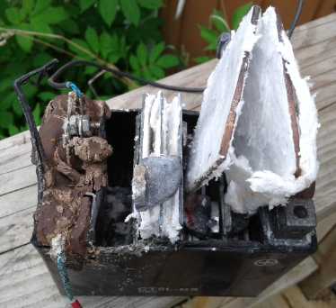 On
the
7th
I chiseled a new PbO2 electrode free from the
"motorcycle" battery. As I started to insert it into the electrolyte in
the cell I heard a slight fizzing sound. Then I remembered hearing that
the previous time, too, when I had filled the cell with electrolyte. I
had hoped it didn't mean much of anything, but given the results, it
probably meant that this electrolyte was spontaneously discharging the
PbO2 to PbO, which wouldn't further react with the zinc. Without going
any farther I pulled it out. The electrolyte was probably the problem.
Rats! There went yet another of my seemingly "ideal" electrolyte ideas.
On
the
7th
I chiseled a new PbO2 electrode free from the
"motorcycle" battery. As I started to insert it into the electrolyte in
the cell I heard a slight fizzing sound. Then I remembered hearing that
the previous time, too, when I had filled the cell with electrolyte. I
had hoped it didn't mean much of anything, but given the results, it
probably meant that this electrolyte was spontaneously discharging the
PbO2 to PbO, which wouldn't further react with the zinc. Without going
any farther I pulled it out. The electrolyte was probably the problem.
Rats! There went yet another of my seemingly "ideal" electrolyte ideas.
So I dumped out the cell and went and got a jar of
potassium hydroxide, and mixed up a batch of this dangerous stuff. If
it had to be, it had to be. If it worked, and then if an ion exchange
membrane worked, then one might even go for something that would really
dissolve the zinc like potassium chloride. First to make sure the KOH
worked. It's what everyone else uses. How could it not?
Making Barium Hydroxide?
On another note, if the barium carbonate won't react to
'set' as glue, perhaps converting it to a more reactive substance would
work. The temperature to "calcine" barium carbonate to barium oxide is
apparently 1237°C (2259°F). This would be a tough job for the
mini kiln (which as I recall takes about 4 hours to hit 'cone 6',
2300°F and it doesn't get any hotter), but theoretically it should
just work. Success would be determined by weight loss of the material:
BaCO3 + heat => BaO + CO2
From the atomic weights of these elements:
137 + 12 + 3*16 => 137 + 16 [ + 12 +2*16 -- gas]
197 => 153 [ + 44 that floats away]
I might just try half that much (3.01*10^23 molecules
according to Avogadro, and probably about half an avocado too): 98.5
grams of carbonate should make 76.5 grams of oxide. The oxide will
convert to hydroxide in water. Whether that is something useful to work
with I don't know. Perhaps to make barium metasilicate it could undergo
an exchange reaction with some other silicate... like soluble sodium
silicate, perhaps, to make sodium hydroxide and barium silcate?
(...Another reason to fix the mini kiln.)
When I fixed the kiln and went to fire the first
HAT36V-50A socket, I looked at the temperatures table. Cone 6 is only
1235°C. So it'll be dicey whether or not I can make the hydroxide.
It could be like trying to boil water at 98°. Or thaw ice at -1.
But soon a new idea occurred to me and the question was: did I need it
anyway? It didn't look like it.
Nafion Delamination
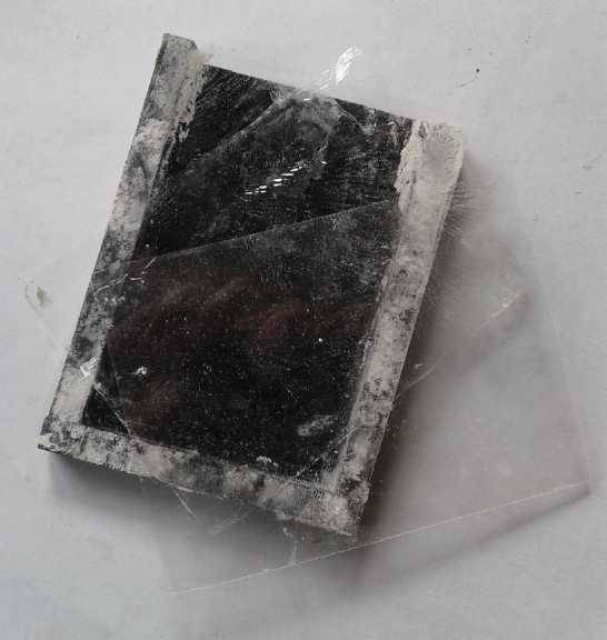 When I looked at the cell pocket in the sink
I discovered
that the fabled nafion membrane had delaminated into 3 thinner sheets.
Egads! Perhaps the methyl electrolyte was responsible for that, too?
Additionally, the barium 'glue' was still soft and the inner sheet
readily peeled off it. It was only "sort of" glued on.
When I looked at the cell pocket in the sink
I discovered
that the fabled nafion membrane had delaminated into 3 thinner sheets.
Egads! Perhaps the methyl electrolyte was responsible for that, too?
Additionally, the barium 'glue' was still soft and the inner sheet
readily peeled off it. It was only "sort of" glued on.
I had heard nafion had surface and interior "layers", but
I thought they were a surface treatment within the single sheet.
Apparently it's 3 entire separate sheets. How do you glue them back
together? Will they work that way, unglued, or is there some magic
trick occurs at the boundary between two layers? ...Or are the outer
layers just some permeable protection for the inner layer?
I read up
on it again and found things I'd glossed over previously. Nafion
doesn't just let tiny ions like H+ (protons) pass through as I had
previously understood. Really it lets any positively charged ions
through, but not negative ions. It was therefore useless for any
alkaline purpose. It would lets the zinc ions pass, but not the
hydroxide ions that make alkaline reactions work.
What I needed was just the opposite: a membrane that let
negatively charged ions through but not positive. That would stop the
zinc ions from migrating, but allow the hydroxide ions to pass. Then I
thought: the osmium doped acetal ester film!
Then, how to employ it? I could paint it on a sheet of
flimsy cellophane, but like the nafion, the slightest leak around an
edge somewhere would let the zinc ions through and nullify the effect.
What about using a nickel positive electrode and painting
the film directly on that? The zinc ions could enter the solution until
it was saturated, but they couldn't penetrate the nickel electrode.
Since the nickel oxyhydroxide to nickel hydroxide reaction is NiOOH
==> NiOHOH, seemingly only a hydrogen ion need move through the
membrane. That sounded like nafion again. Or did the water have to get
to the nickel for it to grab off the H+ ion and ozidize, releasing an
OH- ion? It seemed like a choice unlikely to give good results.
Film-On-Electrode?
Then by the 11th I started to wonder, what would happen if
I
painted a film of my osmium doped acetaldehyde directly on the zinc
electrode? Then it would be an ion selective film that would keep the
zinc out of the water entirely. Could it let through OH- ions (atomic
weight 17) to form Zn(OH)2, while preventing Zn++ ions from even
contacting, much less entering, the solution?
That too seemed a little dubious. It's simply understood
that an electrode surface has to be in contact with the electrolyte to
work. Still... the film should let the reactive ions through wherever
it was placed, right? If it did work, it
might just solve all the problems with zinc. It seemed worth trying.
Lead doesn't work!
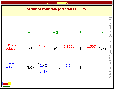 I put one lead
dioxide electrode and the same strip of zinc in distilled water to
rinse off anything that might be there. I heard a fizzing sound again -
apparently just the porous lead electrode letting out its air? Then I
put them into a cell space in the commercial lead-acid battery. I
filled it with 40cc of 20 wt% KOH solution. The voltage read just
.683V. What? A charged zinc electrode (-1.24V in KOH) and a charged
lead dioxide electrode (+.48V in KOH) should be 1.72 volts. At least
when shorted they put out almost 2 amps, but where was the voltage?
I've seen no indication anywhere that lead dioxide wouldn't work
in alkaline, KOH. Zinc is well known to do so.
I put one lead
dioxide electrode and the same strip of zinc in distilled water to
rinse off anything that might be there. I heard a fizzing sound again -
apparently just the porous lead electrode letting out its air? Then I
put them into a cell space in the commercial lead-acid battery. I
filled it with 40cc of 20 wt% KOH solution. The voltage read just
.683V. What? A charged zinc electrode (-1.24V in KOH) and a charged
lead dioxide electrode (+.48V in KOH) should be 1.72 volts. At least
when shorted they put out almost 2 amps, but where was the voltage?
I've seen no indication anywhere that lead dioxide wouldn't work
in alkaline, KOH. Zinc is well known to do so.
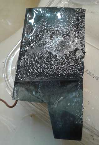 I pulled out the zinc plate. It seemed to be
coated with
something, especially on the side facing the lead... it looked like
maybe fine particles of lead or lead oxide. No lead should be coming
off the lead oxide electrode?!? Apparently lead dioxide [more likely
lead tetra-hydroxide in alkali] actually doesn't work in KOH
electrolyte - one of few things I've heard of that doesn't. That's
probably why it didn't work in the pH 13 mix of KOH and CH3OH, too.
I pulled out the zinc plate. It seemed to be
coated with
something, especially on the side facing the lead... it looked like
maybe fine particles of lead or lead oxide. No lead should be coming
off the lead oxide electrode?!? Apparently lead dioxide [more likely
lead tetra-hydroxide in alkali] actually doesn't work in KOH
electrolyte - one of few things I've heard of that doesn't. That's
probably why it didn't work in the pH 13 mix of KOH and CH3OH, too.
Looking at the chart, if the PbO2 even at just .47V
spontaneously discharged itself to PbO then we'd have: -.54V - -1.24V =
.7 volts. Just about the voltage it actually had! The fizzing sound
then probably really was the second oxygen bubbling off -- even in
distilled water? Maybe there really was no mistake in the diagram that
I "corrected"?: +2.47V would definitely explain it fizzing off almost
instantly, as it did.
OTOH, this pourbaix diagram indicates the +.47 at pH 14 is surely right:
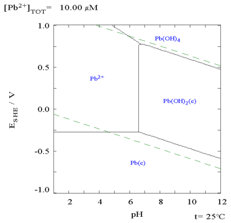
I thought a .47 volt lead dioxide/tetra-hydroxide
electrode seemed like a no-brainer. The diagram doesn't say Pb(OH)4 is
dissolved. OTOH... it doesn't say it's solid, either. (Then again, it
claims it dissolves in acid (Pb++), which we know it doesn't in sufuric
aicd.) Maybe it just
disintegrates and turns to powder? Lead as an electrode substance seems
to just leave me more confused all the time.
Ni-MH "D" cell take-apart
I decided I should go to nickel for a plus side.
Nickel-zinc in alkali is well known. My technique would be simpler than
making a nickel electrode since in KOH it could be a typical commercial
one: Take apart one of my dead NiMH "D" cells and unroll the nickel
oxyhydroxide electrode from it. (If that one didn't work, try a
different one having a different voltage reading. Some of the dead
cells say .4 volts, some are .7, and only a couple are 0. Some of those
electrodes if not all of them have to be good!)
The one I picked said .22V. The metal can was pretty tough
but I peeled it open eventually. When I had the wrapping off and
unrolled the electrodes, they were dry, but as I unrolled further, the
middle area was quite moist. I've long suspected that's why they go
bad: they dry out inside. Nothing else wrong! Maybe I should try
throwing "dead" ones in a tub of water after all!
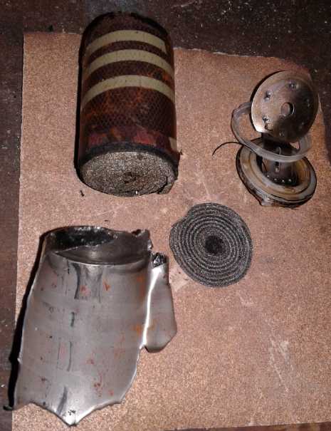 I peeled off the label then got a small pair of diagonal
cutters and
started peeling off the outer case. It was tough going, but I got it
down eventually to where the innards fell out. Even a simple little dry
cell had a lot of intricate pieces. The can was 24 grams and
all the case parts together were 35. (A whole cell IIRC is 169g, so
that's only 20% non-contributing.)
I peeled off the label then got a small pair of diagonal
cutters and
started peeling off the outer case. It was tough going, but I got it
down eventually to where the innards fell out. Even a simple little dry
cell had a lot of intricate pieces. The can was 24 grams and
all the case parts together were 35. (A whole cell IIRC is 169g, so
that's only 20% non-contributing.)
At the top of the rolled-up cell, a fine nickel mesh
extended a little above the oxide powder impregnated section. This
contacted (by pressure only) a round piece of nickel mesh, which
contacted an elaborate nickel plated top cover. Thin plastic insulating
rings kept the cover (positive terminal) from touching the outer can
(negative terminal).
At the bottom the rolled-up metal hydride electrode
protruded from the separator, akin to the nickel at the top, and
touched the bottom of the can to make the connection.
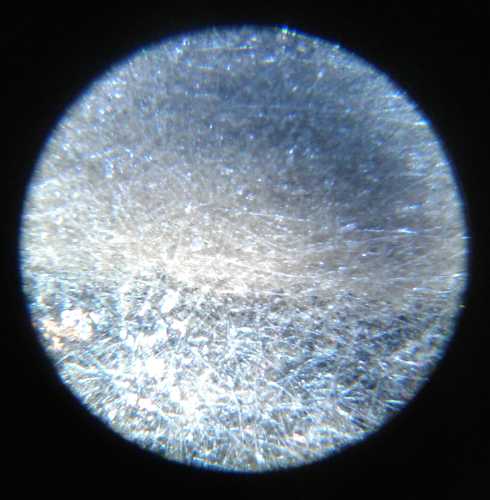 The separator
seemed to be some sort of very thin fabric -
it ripped more like woven cloth than paper, along a straight line. But
under the microscope it looked non-woven.
The separator
seemed to be some sort of very thin fabric -
it ripped more like woven cloth than paper, along a straight line. But
under the microscope it looked non-woven.
Measuring the separator, it was
50cm long (x2 = 100cm since it has to
be double). The electrodes were about 4.8cm tall, so the interface
surface area was 4.8 x 50 x 2 or 480 sq.cm. At 50 mA per sq.cm that
would be 24 amps. The manufacturer claimed... I think it was... 30 amps
and 50 momentary, but of course they wouldn't run long with such
currents. 30 amps would be 62.5mA/sq.cm. That is high current.
Nickel-zinc
 The edge of the nickel hydroxide electrode
strip, showing the fine nickel mesh.
The edge of the nickel hydroxide electrode
strip, showing the fine nickel mesh.
Where the electrode powder is compacted onto the mesh, little silvery
flecks
of mesh can be seen at the surface. (40x)
 The electrodes both
broke into short sections as they were
unrolled. The metal hydride one was hardly more than flakes on the
separator sheet.
The electrodes both
broke into short sections as they were
unrolled. The metal hydride one was hardly more than flakes on the
separator sheet.
In the .7mm thick nickel hydroxide one the porous oxide
powder was compacted onto the flimsiest imaginable nickel mesh, which
broke apart without any fight except where it stuck out from the powder
section a bit at the top and bottom. A thin strip of nickel crimped
along the
top edge of the mesh touched against a thin round sheet of nickel that
itself pressed
against the top button. Under a microscope bits of the mesh were
visible at the surface here and there through the powder.
One suspects the powder would be a similar nickel
hydroxide/manganese oxide mixture to the ones I've formulated, as
described in much earlier issues of TE News.
I used one section of it and attached an aligator clip
leed with a very light wire to the delicate strip. Then I put in the
sheet of zinc. The voltage measured 1.2V but there was only a few
milliamps of current drive.
I didn't much like charging a charged zinc electrode - as
I've seen, it forms brittle zinc hydride. But obviously the nickel was
discharged to hydroxide and wouldn't do much until charged. (That's
probably why it didn't catch fire as I was opening the cell!) I started
charging it at 1.9 volts (at about ~15mA through a milliamp meter that
had some resistance). It didn't seem like much. But after 15 minutes it
seemed to be over 1.7 volts and would put out over 150mA. (Later even
1/2 an amp momentarily.)
While I was charging it I remembered that a nickel
hydroxide electrode can be charged by itself by putting it in bleach.
Well, never mind!
NiZn @pH 14: +.49V - -1.24V = 1.73V. And it seemed to like
to stay above that voltage for an hour or more. Self discharge seemed
lower than many of my cells, but it was still there. In a couple of
hours it was down to 1.68 volts. Overnight it was down a little more
and only put out 60 mA if shorted. Since this is a chemistry known to
work fine and to hold a charge, I'll go with my earlier surmise and
conclude it's because of air getting into the cell (which it certainly
is) and discharging the negative. Evidently lead-acid is about the only
rechargeable type that doesn't have to be rather well sealed. (And that
would be owing to the very low reaction voltage of metallic lead in
acid.)
12th: Actually, I could test which electrode it is by
putting in a new zinc electrode. If it's only the negative that's
discharging, the voltage and current will come up again. The old zinc
plate was covered in crud again,
this time more evenly on both sides of the plate. It would seem lead hydroxide or lead
tetrahydroxide is probably soluble in alkali. So as dissolved lead (or
possibly as a powder in suspension?) enters the electrolyte, when it
touches the zinc (its reaction voltage being lower than that of zinc)
it is discharged to metallic lead as a rough, coarse plating on the
zinc. And there was enough left in the electrolyte to coat the zinc
plate all over again.
With the new electrode, voltage rose to 1.664. Current
drive stayed at about 60 mA. Was that because it was a smaller piece of
zinc, or because current was being limited by the other side? It looked
more like it was the nickel side that was losing voltage and current
drive. I don't remember anything about that side being affected by air.
I put it on charge and the current was much higher, about
45 mA instead of 15. Perhaps that was because the new electrode didn't
get coated with lead particles? - it seemed to stay smooth. And after
1/2 hour of charging, discharge current went up to 1/2 an amp, with a
momentary reading of over an amp. And afterward the voltage recovered
much faster. At 11:00 PST it was at 1.755v; at 12:00 1.748v; 1.730v at
15:30; 1.722v at 18:15. A brief short circuit test then showed it still
started at 1/3 of an amp and settled at 150 mA after a few seconds. It
recovered to 1.717v. ... 1.709v@23:30. But a small voltage drop equates
to a large loss of stored energy.
My little chunk of the nickel oxide electrode was about
4.5cm * 4.8cm = 21.6 sq.cm. At 62.5 mA/sq.cm we would have 1.08 amps.
That's ignoring that the zinc strip was only 3.5cm wide, the tops of
the electrodes were out of the liquid, and there was considerable
separation between the electrodes. (The separator sheet in the dry cell
was very thin.) Only for the briefest of moments when the cell was well
charged were the short circuit currents in excess of this figure.
The 150-500 mA it put out seems reasonable.
Some Conclusions... and some Dissolved Oxygen?
So... I've shown that Pb-Zn in alkali, while it sounds
good, actually doesn't work. The methyl hydroxide electrolyte has been
neither proven or disproven, since I only tried it with lead oxide,
which doesn't work. And I've proven that Ni-Zn in KOH works fine. As if
we didn't already know that. But it has that notoriously short cycle
life. And since it has the similar unacceptable high self-discharge as
all my other cells when Ni-Zn is not noted for unacceptably high self
discharge, the problem must really be because oxygen continuously
absorbs into the water and causes discharge.
Hmm... Flash! Not to mention, that there is probably an
atmospherically balanced amount of oxygen already dissolved in the
water when I mix the electrolyte. I had never considered that there
might be oxygen already dissolved in the water and no way to get it out
of the cell! This topic has never been mentioned in any of the battery
literature I've read. Hmm, is there a way to purge the dissolved oxygen
from water/electrolyte? Then I thought, that flooded alkaline cells
always have air inside the cell, and the buyer fills them with regular
water. Maybe the amount isn't enough to worry about unless fresh air
keeps entering? I decided to go with that idea.
Nafion Versus Osmium Doped Film
When I was young I would study every specification for an
integrated circuit in great detail. If this was connected to that, and
that to the other, would all the circuits together meet the needed rise
and delay
times at every temperature and in every situation? Today I'm a great
one for glossing over vital points and making unwarranted assumptions.
And "the devil is in the details", as they say.
After the nafion delaminated I re-read about it on
Wikipedia. Somehow I had got the idea that the sulfonic acid parts
passed only small ions like H+, and therefore Zn++ was too large to go
through it. On re-reading I discover that it passes any "+" cat-ion,
but won't pass "-" an-ions. Therefore the Zn++ ions would go right
through it. It might block the OH- ions, but it's probably not as
useful as it would seem.
Also it is apparently made for use in an acidic
environment rather than alkaline - as implied by its intended purpose
of passing 'H+' ions and the fact that it itself is acidic. And by its
use of some 'glue' that falls apart in even moderately alkaline
electrolyte (the CH3OH [+ trace KOH yielding pH 13]). (I suspect the
flimsy center sheet is the actual nafion and that the outer pieces are
just there to protect it and give it strength.)
On the contrary, what I hope is that the osmium doped film
will do is allow anions to pass and block cations, in an alkaline
environment. And that by painting it directly on the zinc sheet
electrode, I won't have to find some way to glue a sheet to completely
block every edge.
There is some hopeful if not wishful thinking in all this,
but if it works, it will be the zinc electrode protector that makes
zinc electrodes last and hence changes the whole battery ballgame.
The Filmed Zinc Electrode
Meanwhile I had decided that as the zinc was still picking
up bits of lead in the lead-acid cell chamber I should use another
piece, fresh electrolyte and some other container. The big cell seemed
too big for just using bits of the NiMH'es nickel electrode. I had a
couple of small ones I had made long ago (2012) and I used one of them.
I made
a new lid, trying to eliminate air gaps as much as possible. I tapered
the edges so it would fit like a cork in a bottle. But I had to file in
slots for the electrode terminals. I did my best to keep gaps to a
minimum. It wouldn't be perfect unless I glued it. ...But would the air
at the top of the cell, and the electrolyte with (no doubt some)
dissolved oxygen in it, cause self discharge anyway even if it was
perfectly sealed? Hopefully that wouldn't be significant.
I decided to use the same plastic separator grill material
I had used earlier, on which the deposition of dendrites was clearly
visible, as shown in TE News #128 If there weren't any, it would be in
stark contrast to the previous test.
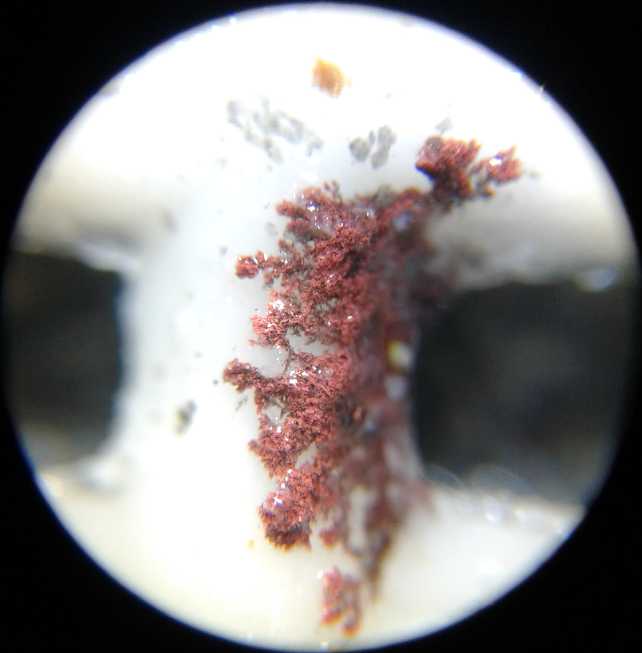 A dendrite growing across the white separator
grill in previous experiments.
A dendrite growing across the white separator
grill in previous experiments.
(TE News #128. This one is apparently mostly copper - some silvery zinc)
And I used several more chunks of the "positrode" from the
NiMH cell. I took a piece of cupro-nickel sheet to make a current
collector, which they would just press against. Their nickel edges
should make good contact.
Finally there was too much space, so I stuck in a chunk of PE foam
plastic so the electrodes would lightly press together - especially so
the plastic grill was in contact with the zinc 'trode and the nickel
oxide bits were in contact with the cupro-nickel sheet.
I filled the cell with 50cc(?) of 20% KOH. The voltage read 1.422
steady. I put 1.9v charge on it and it popped up over 1.8v drawing
~60mA and slowly started rising. Current dropped to ~20mA. After just a
few minutes I stopped the charge and shorted the terminals. After
momentarily giving 3/4, 1/2 and 1/3 of an amp, it put out .20 amps
steady for several seconds until I stopped. It recovered to 1.689v then
started dropping. I put it back on charge at 2.0v (60mA, dropping to
40) and the cell voltage passed 1.9 and climbed slowly. With another 15
minutes of charging it was .25 amps steady.
Now... how long do I want to charge the already charged
zinc electrode for to charge the discharged nickel side to
oxyhydroxide? And what is the relative storage of each side? Probably
way more nickel than zinc, but I didn't even weigh either side to know
how much there was.
OTOH, the first important thing of note was that the zinc
electrode, although painted with the osmium doped film, was WORKING!
That was one of the questions in the process. Either that or the film
had dissolved in the caustic alkali. If it had done that, I could still
try the methyl hydroxide electrolyte. But for the moment I wasn't about
to open it and look. (Could I even tell if it was there or not?)
Cycle Test #1
The next part of the experiment would be to do discharges
and recharges and see if the cell shorted out after one or several
cycles. Then it would be time to look. First it would have to charge at
least for a while. I left it on for about 3 hours. It got up to 1.87v
and it was drawing .02A. When I disconnected it,usually the voltage
does a gradual fall toward some target. This time it dove down
to 1.781v and I feared I had turned the zinc into hydride and wrecked
it. But then it stopped and just sat there. Instead of a "\_" down, it
was like an "L".
It continued to drop, but at the snail's pace of just half
a millivolt per minute. That's as low as self discharge ever seems to
get in my cells - and never so soon after taking one off charge. When
it was at 1.770 I shorted it. It started at over an amp, hovered at 3/4
amp for 3 or 4 seconds, then went down to 1/2 an amp.
That seemed like very good current from two small
electrodes with about 3 or 4 mm separation. The zinc electrode was
about 3.3cm wide, and the liquid came up to maybe 5.5cm in the cell.
3.3*5.5=18.15sq.cm
1.1A/18.15 sq.cm = .055 A/sq.cm
.75A/18.15 sq.cm = .041 A/sq.cm
.5 A/18.15 sq.cm = . .028 A/sq.cm
Those were notably better figures than I usually get. It
recovered to 1.773 V -- slightly higher than it started out from!
...and then resumed its leisurely dropping. I decided it was time for a
load test. I used a 120 ohm resistor. That was probably needlessly
light, because the voltage only dropped 32mV in the first 5 minutes,
and then went down at the leisurely pace of about 1mV per minute.
(That's a slower drop than my most usual self-discharge figures!)
Current would have been: 1.7v/120 ohms = 14.2mA. hmm... charged it at
30mA for 3 or 4 hours? If the cell was working as well as it seemed,
this could be a very long test.
2019/June/13
Start at 19:15:00:
15 1.763 V (just prior to connecting load)
16 1.739 V (after 1 minute)
20 1.731 (after 5 minutes)
25 1.726
30 1.721
35 1.717
40 1.710 (Dropping faster? - or was it just because I took off and then
reconnected an alligator clip?)
45 1.705 V (1/2 hour mark.)
50 1.699
55 1.694
00 1.689 V (20:00:00 - 3/4 of an hour)
05
10
15 (1 hour)
Very close to the 2 hour mark the voltage started dropping rapidly.
That was good, saying that it was behaving just like a battery run out
of juice. OTOH it also said it had only 28 mA-hours of juice. I'm going
to guess that's all the small, simple zinc sheet had in it, as I used
maybe a couple of amp-hours worth of NiOOH 'trode pieces from the "D"
cell and it had charged substantially more amp-hours than discharged.
Next and rather vital question: would it grow dendrites
and short out the cell on recharge?
Cycle Test #2
I recharged it for almost 2 hours with no evident problems
(yay!), and then did another load test, this time with 60 ohms. It ran
for an hour and 15 minutes at mostly a little higher voltages and
delivering twice the current for a total of 35 mA-H. Would the
amp-hours improve more? Would dendrites short the cell? The way to find
out was more testing. It was well after midnight.
(14th) With the briefest of charges, the cell held 1.73+ volts
overnight. (I guess the top fit pretty well!) The charging currents
seemed to be gradually staying higher longer. But the low self
discharge said nothing was shorting or forming a low resistance between
electrodes. That would seem to be in keeping with finding it had
increasing amp-hours.
Cycle Test #3
Still no internal shorts after the third charge. A quick external short
gave 1.8 amps - 100 mA/sq.cm. That was good current. The voltage drops
during discharge weren't high so I decided to try a 40 ohm load this
time to shorten the test some more. Current would be 1.7v/40 ohms =
42.5mA. The voltages started dropping much faster than with the 60 ohm
test - or even both tests previous. I wonder if there was a bad
alligator clip connection in that test - a bad one may have made it
more than 60 ohms. I'm always struggling trying to get good connections
from alligator clip leeds, and this time I had been having trouble with
one during charging - maybe it was already high resistance. I took it
out and shortened the connection for the discharge. Say it was 30 ohms
in that clip leed: it would have made it 150 ohms and 90 ohms in the
first two tests. That would explain too the "increased performance" in
the second test since the ratio of the two wasn't 2 to 1 but 15 to 9.
40 ohms was definitely too much load for it and the
discharge only lasted 12 minutes. That made the milliamp-hours look
even worse: 8.6.
Cycle Test #4
Here I unraveled a mystery. I used 120 ohms again. It seemed very hard
to get good contact with the zinc terminal tab. (And it was actually
the cupro-nickel tab I was fiddling with.) I switched to yet another
"poor" aligator clip
test leed. And it seems to get worse as the discharge proceeds. By
rubbing the meter probe within the aligator clip directly on the
terminal, the voltage would jump around considerably. After over an
hour, of seemingly falling voltages, it could occasionally be brought
back up to the same voltage it had just one minute into the discharge,
1.733 volts! Suspicious, I checked right on the resistor leads
themselves with another meter. But the full voltage was indeed across
the resistor.
The falling voltages in the discharges weren't from the
battery getting lower at all. They were, apparently, from gradually
increasing resistance at the cupro-nickel terminal tab as the test
proceeded. Then after a lot of frustration and inconsistent results I
finally discovered that it wasn't the terminal at all. As I wiggled the
clips I was slightly moving the whole current collector plate. The bad
connection was inside the cell, between the plate and the chunks of
nickel oxyhydroxide electrode. Internal reactions doubtless explained
why they got worse as discharge proceeded. A better arrangement would
be required for the next cell.
The battery had more capacity than I had thought it had.
The small amp-hour values in the previous tests were wrong. For a while
it looked like it could drive the 120 ohm resistor all day, at least!
Or at this point, maybe it would be all night. There was certainly
little point in checking it every 5 minutes as I had been doing! But
after 3 hours the highest voltage I could coax out of it was 1.700, and
gradually dropping. Was the zinc plate getting discharged, or was it
that I hadn't charged it long enough and the nickel was spent? After
all, it was discharging now longer than I had charged it for, albeit at
maybe at 1/3 the current.
Obviously it could run longer but it was midnight. I
disconnected the load resistor.
(15th) The cell had 1.744 volts in the morning, so it had lost little
to nothing overnight. YAY! I put it back on charge at 9:30 but after an
hour I opened the cell and inspected the separator grill. There were
some little dark specks on it but no dendrites. The specks do doubt
fell off the crumbly nickel side.
When I put it back together I stuck a piece of plastic
behind the foam piece to press the electrode chunks more firmly against
the collector plate. It started charging at 110 mA instead of 90 and
when shorted a bit later it put out 2.47 A for a moment and took a bit
longer working its way downward. 2.47 A / 18.12 sq.cm = 136 mA/sq.cm.
That was starting to look quite impressive.
(Let's see... my "full size" electrodes are to be about
6.5cm * 12.5 cm; 81.25 sq.cm. At .1 A/sq.cm that would be about 8
amps. for a moment. with a short circuit. of course. That's per
electrode pair. If there were 3 nickel electrodes and 4 zincs, that
would be 6 such surface areas for ~50 amps. At a more reasonable 50
mA/sq.cm that would be 25 amps. For 300 amps for a light car like my
Sprint you'd want at least 12 in parallel then, which would also be
around 600 amp-hours. Then multiply by 24 for nominal 36 volts would be
288 batteries. 22 KW of storage. All still pretty speculative, but
starting to enter some ballpark. And how much would all those weigh?...)
Cycle Test #5
Having stuck in the extra piece of plastic, and seeing the
higher currents, I made the next test a 15 ohm load. It put out about
110mA for just 30 minutes before the voltage went for a dive. 55mA-H.
Now I'm wondering... in charging for just a couple of
hours, did I actually put more into the cell than was pulled out?
Cycle test #6
15 ohms seemed like too heavy a load, so this time I tried
27 ohms. At 1.7 volts, that's 63mA. It ran for exactly 3 hours, with
the voltage dropping from just under 1.8 volts to below 1.6 volts only
in the last 16 minutes and then it rapidly fell below 1.5v in the last
3 minutes (to 1.450v at the 3 hour mark). That's about 190
milliamp-hours - almost a fifth of an amp-hour from a very small zinc
sheet electrode. (3 grams? - again somewhere a little under 10%
utilization.)
Well! From 1/2 hour to 3 hours by halfing the load. And
from putting in a chunk of plastic to push the nickel oxide chunks
better against the current collector.
But in order for that to happen, at the two hour mark I
fiddled with the positive current collector. I could wiggle it a bit
from the tab, and obviously it still wasn't making a really solid
connection inside. The first time I got the voltage to go up ~10
millivolts, and and not too long after that, ~7 mV. It would continue
down from the higher value. I got the impression it was the nickel that
was running out of charge rather than the zinc, and that it helped to
move the current collector to better connect some other area. After
that it stopped helping - I couldn't get any more out of it.
The mere fact that I could do 6 charge-discharge cycles on
this cell without apparent degradation (in fact with apparent
improvement) doubtless makes it better than any of my previous cells.
Take-Apart & Inspection
(16th) I opened the cell to examine the components. I took pictures
under a microscope (@ 40x unless one or two were @ 100x):
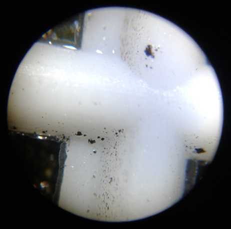 -
The
separator
grill
once again had some bits on it, but no apparent
dendrite growth.
I rinsed off the grill and then tamped a piece of the nickel electrode
on it. Again it had similar looking particles on it. (It later occurred
to me to put in a separator paper next time to block their movement and
verify for sure that they are coming from the nickel oxide electrode
side. But they may just as easily be zinc bits.)
-
The
separator
grill
once again had some bits on it, but no apparent
dendrite growth.
I rinsed off the grill and then tamped a piece of the nickel electrode
on it. Again it had similar looking particles on it. (It later occurred
to me to put in a separator paper next time to block their movement and
verify for sure that they are coming from the nickel oxide electrode
side. But they may just as easily be zinc bits.)
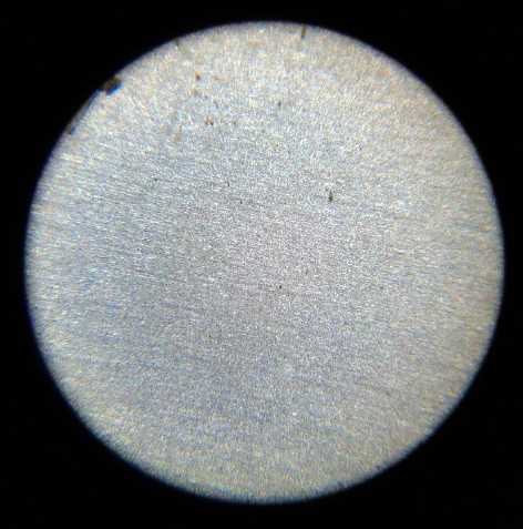 -
The
cupro-nickel
still
just looked like a sheet of metal. Later I took
pictures of a never immersed piece for comparison.
-
The
cupro-nickel
still
just looked like a sheet of metal. Later I took
pictures of a never immersed piece for comparison.
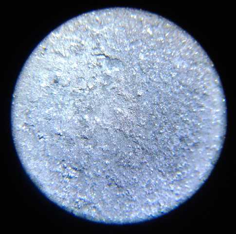 - Zinc Electrode front side after initial use
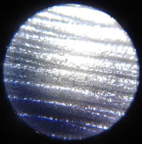 - And the back side, which hadn't changed much since being
coated with the film.
- And the back side, which hadn't changed much since being
coated with the film.
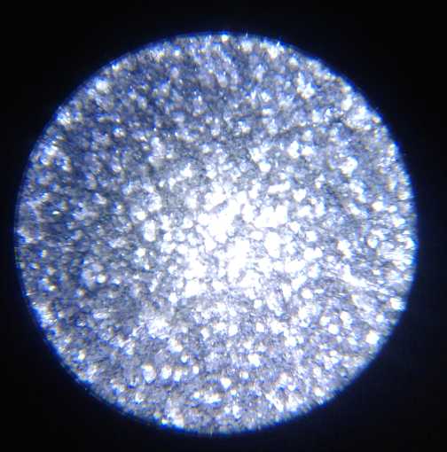 - The next time the zinc electrode looked much like it had
before except now the back
side looked much like the front side. Probably the longer (esp.#6)
discharges had activated both sides of the electrode. Nothing that
looked like dendrites - YAY! Later I took pictures of a sanded and
etched but uncoated sheet of zinc that had never been immersed for
comparison.
- The next time the zinc electrode looked much like it had
before except now the back
side looked much like the front side. Probably the longer (esp.#6)
discharges had activated both sides of the electrode. Nothing that
looked like dendrites - YAY! Later I took pictures of a sanded and
etched but uncoated sheet of zinc that had never been immersed for
comparison.
When I put it back together I put in a second separator
sheet and another piece of plastic behind the nickel electrode chunks
to press them together more. It didn't seem to want to put out much
more than 2 amps when shorted (the extra separator sheet?), but it
continued putting out around 1.5 amps for several seconds (10?) instead
of dropping quickly to 1/2 an amp. With a 1 ohm load it put out around
1.2 volts which only dropped quite slowly. (The current meter said it
was only putting out .9 amps. HOW much resistance in the test
connections? Hmm, .3 ohms? Actually that doesn't seem either unexpected
or unreasonable.)
Cycle Test #7
Since it was handling current so well, and not wanting
this next test to take another 3 hours, I gave it a 15 ohm load again
for this test. The previous test with 15 ohms had ended when the
voltage dove off a cliff in 1/2 an hour. This time it was still going
strong at the 1/2 hour mark, putting out 1.665 volts. It ran for an
hour and 25 minutes. The only things
to attribute this to are (a) it wasn't fully charged last time, or more
likely (b) the nickel oxide sheets being pressed together better,
making better connections in the positive electrode.
Following a few hours recharge after this, I found that it
held over 2 amps short circuited until I stopped at about 10 seconds.
(17th) I had had enough of lengthy cycle tests and went on to
experiment with getting more amp-hours from the zinc electrode.
More Amp-Hours from Zinc?
...Okay, I wrote the following before I discovered the
zinc sheet had higher capacity than it showed before cycle test #4.
A plain sheet of zinc is still a low surface area electrode with low
utilization and this still looks like a great way to get excellent high
capacity from a
coated zinc electrode - the sort of specs wanted for commercial
manufacturing.
If the coated zinc was working, but had low capacity, how
to get more amp-hours from it? It weighed 2 or 3 grams, a theoretical
capacity of over an amp-hour or even two. But a simple piece of sheet
metal, if it's not dissolving during discharge (as in a Mn-Zn cell in
chloride electrolyte), doesn't have much surface area.
The obvious thing to increase the surface area is to use
zinc powder and grit of various grades. But then, how are those
compatible with the osmium doped film? Instead of a thin surface film,
perhaps all the interstitial spaces would have to be filled. Osmium
isn't cheap. I've been trying to make cheaper batteries, not more
costly ones! Perhaps one might fill all the interstitial space with
electrolyte, and then (somehow) just coat the entire outer surface with
the film? The zinc particles inside could perhaps dissolve, but they
couldn't much go anywhere even if they did.
An interesting thought (without doing much to solve the
above problem) was that the lead particles had made a very rough
plating
with a lot of surface area. If a zinc sheet was plated with lead, and
then placed in zincate solution and the lead plated with zinc, that
would give a high surface area zinc sheet. (But then the lead would add
weight without adding capacity. I guess I won't try it.) Hmm... One
could instead sprinkle zinc oxide particles on a zinc sheet layed down
flat and plate them on for a similar effect. Probably smoother (taking
less osmium film material) but still porous. If one plated it and then
coated it with the film, the particles couldn't come loose and fall off
on discharge, either. That should be well worth a try!
I took the second small ABS tall, thin cell and made
electrodes to fit (cupro-nickel and zinc sheets) and a new lid for it,
again making it pretty tight against air.
On the 17th I tried plating the zinc electrode (4.20 grams) for
that cell per the above. I poured some Caswell "Concentrated Zincate
Solution" into a shallow plastic tray, and then I dumped in some zinc
oxide powder, which proved to be lumps, and tried to mix it up. I put
in a zinc positrode and the negatrode to be plated, connected them, and
turned on 1.5 volts.
At first nothing seemed to be happening. But a few flakes had plated
around the edges. It turned out to be a long process and patience was
the key. I dumped in some more zinc oxide, and later diluted it all
with some water, which seemed to help.
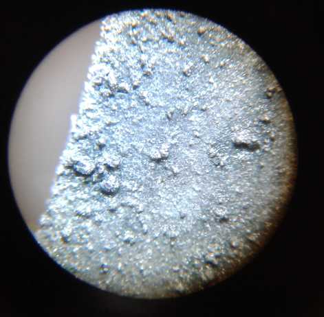 Top side near one edge
In addition to zincate ions, lumps of zinc
oxide resting on the plate turned to zinc and plated on.
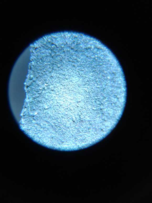 Bottom side was less lumpy since there were no
lumps of zinc oxide resting there
Bottom side was less lumpy since there were no
lumps of zinc oxide resting there
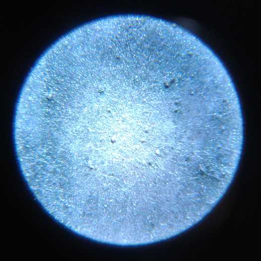 The middle of the faces didn't get very much
coating -
The middle of the faces didn't get very much
coating -
mainly just some oxide lumps.
While it was working I looked on the web. Everything came
up old papers with abstracts, that various hucksters wanted to charge
you quite a lot of money for to read the whole thing. There was one
with a list of ways to make porous zinc electrodes.
Then I thought to go to youtube. There I found NurdRage,
who posted various chemical techniques. He had a video doing basically
exactly what I was doing - zincate solution (from NaOH), zinc oxide
from a pottery supply, and all. It seems the zinc oxide turns into
zincate by itself to the limit of solubility. And as I surmised, so
does the zinc positive electrode. So gradually any zinc oxide you throw
in, and any zinc touching the positrode, will turn into zincate and
plate onto the desired electrode.
One difference was that his container was a beaker and the
plate he was plating to [a copper circuit board] was almost vertical in
the beaker.
My electrode plated around the outside edges, mostly
ignoring the center. I guess lying horizontal on the bottom of a tray
of shallow liquid isn't ideal. His plated especially in the center, but
not ignoring the edges. He left his going overnight and there were
great gobs of porous zinc plating on it, even wrapping around the edges
of the circuit board. (Having attained this fine result, he then
scraped all that plating off and into a beaker. Horrors! I guess he
wasn't making an electrode.)
My electrode weighed 4.30 grams after plating.
Theoretically I had added a whopping .1 grams, .82 amp-hours to it, but
my scale only moves in .05 gram increments, which may move up or down
.05 with nothing happening, so it could be more or less.
Osmium Supply
On the 18th everything seemed rosy and settled. Everything
seemed to be working great and the path ahead seemed straight. I had a
suspicious thought. Production of new chemistry solar panels was
sabotaged a few years ago by silicon solar panel makers, who having no
use for it themselves, bought up the rarest vital ingredient: all the
available gallium with options on the whole of the future supply.
Having got investment and done the work and set a factory up for
production, and with all the great promise for better, cheaper solar
panels, the company went broke because they couldn't get gallium. This
"dog in the manger" tactic is illustrative of the dirty tricks existing
businesses are permitted by our society to use to prevent competition.
(You've probably heard this story before in some TE News issue.) And
long life nickel zinc batteries would threaten lithium battery
producers with billions invested in the technology. So I thought I'd
get a bit more osmium.
The film only needs a trace of Os, but it's the second
rarest element to be found in the Earth's crust and so it's very
expensive. I used osmium powder before - that cost far more yet than
solid pieces, so I thought I'd get a solid piece. I ordered a 20 gram
ellipsoid 'droplet' for about 900$C. (So much money for less than 1cc
of metal!) I trust, without looking it up for now, that there is some
practical means to turn it into powder or dissolve it into the mix.
And without trying to figure out quantities, I expect that
should probably last for the foreseeable future including limited
production.
Oh No - Another Problem!
I played a bit with the cell now and then, driving a heavy
load or seeing that it hadn't lost much energy overnight, and I charged
it once, until the evening of the 19th. I was really pleased with the
continuing good performance. Then something was wrong. No dendrites,
but it turned out the sheet of zinc had fallen apart, separated into
two along the waterline.
I don't remember reading anything about anything like that
in the battery literature! OTOH my previous zinc terminal tabs had
become brittle zinc hydride and broken off before.
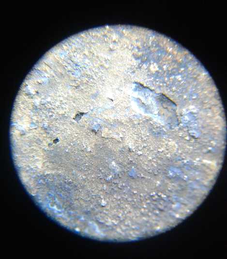 The top above water part and the lower
underwater part under microscope
The top above water part and the lower
underwater part under microscope
I have a theory... If it was overcharged it would bubble
hydrogen. The coating should prevent it from forming zinc hydride in
the water (I trust), so the hydrogen would bubble up to the water line.
If there was the slightest weakness in the coating there, hydrogen
bubbles all around the electrode would turn the zinc to hydride and a
crack would start and spread, along the waterline.
This theory seems to fit, anyway. I figured at worst I
could paint or otherwise solidly coat the zinc from below the waterline
to above the point where it comes out of the case. This time at least
the terminal tab seemed to be "good as new". I had wrapped it with
magic transparent tape and so kept the reactions away form it. And
there may be easier ways. Perhaps I'll try two coats of the ion
selective film instead of one.
The two pieces seemed considerably different from each
other, and the lower one seemed thinner than originally. At first this
puzzled me, but of course... the top one was in the air; the bottom one
was in the liquid. Later I weighed them both together: 2.7 grams. It
was very close in size to the new electrode, which weighed 4.2 grams
before plating. So it had definitely lost some substance. So much for
it having no degradation. If it was losing substance off the surface,
where was the osmium?
And would it stop at some point, reach an equilibrium, or
would the zinc continue to get thinner until it fell apart somewhere?
If the former, perhaps I just needed thicker pieces of zinc. (This
would be a surprise - I has considered that most any thickness was just
wasting the interior atoms. But if the surface ate in as far as half
way from each side, then the zinc was being fully utilized and the
"current collector backbone" portion in the middle was being totally
disintegrated. It could also be a problem as the readily
available zinc sheets
I had found were the "moss killer" roofing strips which were all pretty
much the same. Or perhaps with a porous plating the sheets would be
less affected. Perhaps I should order some thicker and specified purity
sheets?)
Was my 'breakthrough' really the final answer? A partial
answer? I've had what I thought were breakthroughs before too, only to
find problems or incompatibilities between different parts of the cell.
I took the cell apart. It seemed to leak a bit anyway.
Next Cell
(20th) But with it having no apparent dendrites, it had to be an
improvement over other zinc electrodes. Would the metal only be
affected to a certain depth into the surface? Would the porous coated
electrode fare any better because the surface was deeper? What would
happen if I painted on two or three coats of the film instead of just
one for better coverage? Some more experiments were in order to try to
answer the questions.
So I put together the new slightly smaller cell. First I
coated the porous plated zinc electrode with three coats of the film.
Perhaps it would make it better or seal the surface better or
something. Of course with the plating being mostly around the edges, a
lot more of the liquid penetrated the pores there than went onto the
relatively smooth center area. I had to dip the brush into the liquid
to get more, more often.
I put the cell together with the nickel oxide bits from
the previous cell, so the voltage started out high - all charged. It
didn't seem to put out as high currents - less than 1.5 amps shorted,
and higher voltage drops under load. I mostly attribute this to (I
suspect) a poorer connection from the nickel to the current collector.
Nonetheless it seemed to work fine. I foolishly started a discharge
test with a 60 ohm load at 11 PM. It ran 3 hours, and the voltages were
lower than I expected before it finally started to peter out. It turned
out to be in the wiring - I hooked some skinny, lightweight clip leeds
to the somewhat flimsy terminals, and the meter was on the wrong side
of those. Why was the voltage getting so low, yet it wasn't rapidly
dying? I finally put another meter straight on the terminals and found
the battery voltage was somewhat higher than I had been reading it as.
The cell averaged maybe 27mA, 24mA and 21mA over the 3
hours. That's 72mA-hours. (Current was separately metered, so those are
the actual figures, which say the "60 ohm" load was about 65 ohms with
all the crappy connections and skinny wires.) 72mA-H compares well with
the first test of the first cell: 28mA-H.
The cell seemed to have a high self discharge after the
first cycle. I took it apart and rinsed some sludge out of the bottom
but it didn't help. Then I changed the electrolyte... which I had
poured out of the first working cell and was still using because the
first cell had been working fine. To my mild surprise that solved the
problem. ...For one cycle. It held charge overnight fine, but after the
next discharge it didn't recover as expected and after being charged,
once again it would discharge itself. I took it apart and inspected it,
but nothing was crossing the separator grille. I changed the
electrolyte again (I spilled it in disassembly anyway), this time
without any improvement.
I could write this off as yet another puzzling failure of
chemistry or technique and go on to try something else... except that
two of the three components, the nickel oxide electrode pieces from a
commercial cell and using KOH for electrolyte, were not experimental.
Neither was zinc per se. Of all the many things I've tried over the
years, here the coating on the zinc was the only experimental thing in
the cell. And... this cell seemed to work sometimes, and the first cell
with the same coating, albeit one coat on a rather plain surface
instead of three coats on a more porous surface, had worked pretty well
for a while and hadn't done anything like this.
One difference to the first cell belatedly occurred to me.
I had folded a piece of the separator cloth from the NiMH dry cell
around the zinc electrode, to separate it better from the nickel side.
(If little bits still appeared on the grille, they came from the nickel
side. If not, there were probably some coming from the zinc that now
couldn't get there.) When I opened it, I removed it. But it had bits of
crud from the old electrodes stuck on it. And I don't know which side I
had touching the zinc. Perhaps it introduced some foreign material onto
the zinc surface? A new zinc electrode was doubtless called for.
Another thing I noticed later: my first bottle of
distilled water had run out. The new bottle said "ozone added". Huh?
Why would one add a potent oxidizer to what was supposed to be pure
water? I had rinsed the parts in it. Would it persist? Might it make
some undesired reaction? I'd better go back to the first store and the
other brand!
When well charged, the second cell put out over 3 amps
momentarily: 165mA/sq.cm. That would suggest that a porous electrode
handles more current than a flat sheet, in case we didn't already know
that.
I decided to charge this cell, #2, overnight in spite of
all the hydrogen that would bubble off the coated zinc, and see if it
helped.
On examination of the Zn electrode after use and with
overcharging having bubbled hydrogen off of it, it didn't look as bad
as previous zinc electrodes. The osmium/coating seems to help protect
it. And the separator grille, while it had bits of crud on it, still
didn't have any dendrites.
The bits of crud were thickest near the bottom. This of
course is why lead-acid cells have a space underneath the electrodes
for crud to drop down into. They fail when the crud has built up to the
plates, and a "better" PbPb cell is one with a deeper space underneath.
The bits on the grille readily rinsed off in water.
Third Coated Electrode - Second Porous Plated One
In the meantime I was thinking of how to set things up
better to get more even platings on zinc sheets, to make a similar #3
cell (or at least a #3 electrode) with such an improved sheet, and hope
that it would work without issues.
If I made another the same size, etched it evenly, and
could then plate it evenly with .5 grams of porous zinc, it should
theoretically have about 1/2 an amp-hour of charge. (In this I note
that in spite of the uniform black appearance when it comes out, that
the zinc was much more etched around the edges than in the middle -
something else to try and improve if possible and practical.)
* "Scotchbrite" does a better job of scratching up the zinc surface
than sandpaper. (Neither is a substitute for etching it.)
Egg Albumen Coating?
It seemed to me the zinc electrodes needed another coating
on top of the coating to keep them from deteriorating and bits of zinc
from dropping into the separator. My preferred means would be to jell
them, and jelling has now been borne out by two other researchers as
making electrodes "everlasting". But what to use? I started to think
the Sunlight dishsoap (with the sulfonates) should be for the positive
electrode, but not the negative. Then there was agar... I wasn't sure
how that would stand up to hydroxide electrolyte. Okay... what about
egg albumen? "Albumen paper" has been used in photography. It's
"developed" or "fixed" by immersion in sodium hydroxide.
Wikipedia says eggwhite is an alkaline solution (but
probably pH8 rather than 14!), and "ovotransferren is a glycoprotien
that can bind bivalent [zinc!] and trivalent metal ions in a complex."
It seemed to be something worth trying. At best the
coating will stabilize and hold everything together and prevent 'stuff'
from flaking off the electrode, making it far more long lasting. The
worst that can happen is it degrades (at pH 14?), is deleterious or
just isn't useful and I have egg on my face. If you don't try things
that might seem a little crazy, you'll never find the ones that
actually work.
A youtube video on making albumen [for foto paper, by:
Will Salley, 2013] gave me more clues about albumen.
Formula
1 liter egg albumen (30 eggs - no yolks, no stringy bits, just pure
liquid)
15 grams sodium citrate
15 grams NaCl
2 cc glacial acetic acid
30 cc distilled water (Surely can make from 5% vinegar and water? There
was nothing special about adding each ingredient. Hmm... make that 32cc
of 6.3%, to be technically correct.)
Whip with egg beater until it turns into a froth. (He blenderized for
15
minutes)
Put in fridge for 24 hours.
Another video had a simpler process:
100 g egg white powder
700 cc water
Whip.
However, by about the 3rd week in June, after so much
experimentation and trails, successful as things were becoming I had
other things to do and had become a bit burned out with bettery
research. The third zinc electrode with its improvements and albumen
will have to wait for July. (and even then... it's summer!)
http://www.TurquoiseEnergy.com
Haida Gwaii, BC Canada