Turquoise Energy News #134
covering July
2019 (Posted August 5th 2019)
Lawnhill BC Canada
by Craig Carmichael
www.TurquoiseEnergy.com
= www.ElectricCaik.com
= www.ElectricHubcap.com
Feature: Batteries: "Everlasting" Zinc Electrodes! √
(See
Month in Brief, Electricity Storage)
Month In "Brief"
(Project Summaries etc.)
- All the Answers at Once! - Picking Up Steam -
CNC Table - More Things - The Covered Wagon (solar E-Bike) -
Donation
In
Passing
(Miscellaneous topics, editorial comments & opinionated rants)
- Stop Colds Fast with OJ - Homegrown, Homemade Quinoa Flour Bread:
Mmm! -
Another Hair Loss Preventative - Small Thots - ESD
- Detailed
Project Reports
-
Electric
Transport - Electric Hubcap Motor Systems
* Ground Effect Vehicle ("GEV") - only slight progress as usual - wing
shape
and stability
- Testing Ducted Fans, Radio and Motor Controllers -
Revised Ducted Fan
positions: Outboard, in line with wing
* More Unipolar BLDC Motor and Motor Controller Ideas - ? Turns per
coil - Sizing
- Permanent Magnet Assist, Magnet Fitting - Tuned Circuit
Coil Drive - Rotor Design - Figuring Out Activation Sequences
* More Variable Torque Converter Ideas
Other "Green"
Electric Equipment Projects
* 36 Volt DC Wiring & Infrastructure
*
Some Handheld Bandsaw Sawmill Notes - Update
Electricity Generation
* My Solar Power System: - "Floating" Panel Voltage Grid Tie -
Combining More Panels on One Grid Tie or Charge Controller? - east-west
facing panels - Monthly
Solar Production log et cetera
Electricity Storage -
* Dried Out(?) NiMH Dry Cells
Turquoise Battery Project (Mn-Zn or Ni-Zn in Potassium
Hydroxide electrolyte ?)
* Non Dendrite-forming Nickel-Zinc Cells:
- Cost comparison and estimate - Preparing a Zinc Alkaline
Electrode - Electroplating - Egg
Albumen Coating - Assembly and testing - Antimony Sulfide or Zirconium
Silicate? - 14th - Duck Eggs - Electroplating Rack - A Positive
Electrode - Parchment Paper Separator - 3D Printed Positive Electrode
Shells - Ethaline Deep Eutectic Solvent (DES) - Ethaline Electrode Jell
for Zinc? (nope) - Agar Jell (seems to work, including in KOH, but low
currents) - Getting Current - Osmium Doped Film Again + Agar? - Apparently
Successful
and Practical
'Fuzzy' Electroplated, Osmium Filmed and Agar Jelled Zinc Negative
Electrode! - Microcontroller for Cycle Tests and Cycling Cells? -
How Many Ni-Zn Cells for 12 Volt Battery? (Seven.) - Positive
Electrodes and 3D Printers
All the Answers at Once!
Omitting the previously started original wave power
project (from
2006-2007) which I soon ceased to pursue, the inspirations of June
and July bring the original goals of Turquoise Energy in
January 2008 right back and into clear focus:
1. A highly efficient electric car motor, mounted on the outside of a
car wheel.
2. An efficient, friendly, repairable and reliable motor controller for
said motors.
3. Better, cheaper batteries for electric cars.
And when I finally decided a motor small enough to fit
directly on a car wheel at 1-to-1 ratio (at least any in line with how
I was making them) couldn't have the torque to drive it:
4. An efficient variable torque converter to couple the motor to a
wheel - spring 2009.
I made great axial flux BLDC motors by 2012 or 2013. My
BLDC motor controllers work but usually end up with blown transistors
when stressed too hard. (A 300 amp Kellycontroller BLDC controller
finally put the Electric Hubcap motor to work and showed its power.) A
lasting battery cell was elusive until this
June, and I stumbled around in the dark trying various things
mechanical and magnetic to make a torque converter. (I finally had all
the right parts for a mechanical one, but I wasn't putting them
together in a way that worked. The "Magnetic Impulse" torque converter
idea should work, but it needs too many magnets and rotors with too
much copper
to be practical in a car - and it would probably make too much
vibration.)
In 2016 I came up with or ran across concepts for
"unipolar" motors where each coil is activated in only one magnetic
direction instead of opposite directions at different points in the
rotation. From my point of view, the biggest benefits were simplicity
and ruggedness of the high power electronic circuits of the motor
controller. A
unipolar controller couldn't short straight from B+ to B- if a
transistor turned on for an instant at the wrong time, and so the
chance it would blow transistors in heavy use was greatly reduced.
For reluctance motors a 3-phase unipolar controller would
work
because the rotor iron is attracted to either polarity. But (limiting
my imagination to 3-phase motor controllers) I couldn't figure out a
"unipolar BLDC" configuration that would work right and well.
Reluctance motors were however a new type for me, very different from
the ultra-efficient BLDC motors I already knew how to build well. I did
get
a sample reluctance motor (the "ARM" axial reluctance motor) running,
but it needed a lot of changes to be effective, and a reluctance motor
would probably never have the "ultra-efficiency" of my axial flux BLDC
motors (~95%).
An additional potential advantage of the unipolar motor is
that it is amenable to a type of permanent magnet assist that adds the
flux of a permanent [super]magnet, seemingly for free "two for the
[energy] price of one", to that of the coil electromagnet. I would very
much like to try this out and see what actually happens.
Suddenly in July 2019 I have answers for what seem to be
excellent batteries, for rather simple and effective variable torque
converters, and for unipolar BLDC motors that will allow me to make
reliable unipolar motor controllers that won't blow up. Since I already
build great BLDC motors and simply need to create a (4/3 larger)
variant
of the Electric Hubcap motor, this means that I quite suddenly
have answers to all the thorny design questions I've beat my head
against for so many years, in all my main projects.
If the time I have lavished on these projects over the
years had been spent building them in the right or optimal way from the
start, I'd have had them all done long ago. But with the inspirations
finally coming now and having further valuable projects on the go as
well, I wonder when and even if I'll ever be able to build these
marvelous concepts and put together the fabulous, ultra-efficient,
longer range electric car that I now, quite abruptly, see just how to
create.
They will each take a lot of work.
Of course things progress from a beginning, and for new
technology ideas - inventions - from something of a blank slate,
as puzzles with pieces missing. If it wasn't so, the invention would
already exist. I learned as I went. The designs and principles I now
present seem pretty simple (that is to say, easily grasped by those in
the relevant fields), but if it seems like I was really slow off the
mark to take so many years stumbling around to get to such simple
places, it must also be considered that no one else has come up with
any of these things, from any past time to the present day. If they
had, the thing would be out there and I could have just copied the work
-- or perhaps have just gone into a store and bought finished products.
Instead here are some new concepts and designs that never existed
before, for anyone to use to create working models. (I acknowledge of
course all those things developed by previous inventors that I can
just go into a store and buy, or order on line, and which my own new
work is built on top of!)
Picking up Steam
In June I was lamenting that I didn't have time for
projects. In July, with so many answers to imponderables suddenly there
in front of me, I made time. The garden was mostly planted and I did
the minimum watering and almost no weeding. I cut way down on milling
wood.
I skipped naps. I skipped trips to town, where it seemed sometimes the
only purpose to the trip was to check the mail anyway (but I usually
buy a couple of pieces of fresh fruit). Seeing real progress I did
battery experiments and
developments one after another instead of weeks apart.
CNC Table
From a far corner in the shop I brought in the new
Geckodrive, the old CNC table controller box and the CNC table. If I
was to build a new design of motor, this had to work - at least the
router to make the molds. I put
them in my 3D printer alcove (clean, uncluttered... was) and started
putting things together for the CNC router and CNC plasma cutter.
(15th, 16th) I disassembled the stepper motor/limit switch assemblies
to trace out the connections to the DE-9 connectors. (I tried months
ago to get the DE-9 pinouts from "Techno", the company that made it, to
no avail. Too old, I guess. But they were easily traced once opened.)
The CNC table was one "hi-tech" item that wasn't obsolete after 30
years. Then I made up cables to connect them to the "Gecko", which also
used DE-9 connectors but with a completely different pinout. Having got
that far, on the 17th I ripped the old electronics out of the box,
keeping just the power supply, and installed the Geckodrive on the back
panel. I started in on the instructions, testing that the unit worked
properly - the right lights came on, and the CNC table stepper motors
had holding torque.
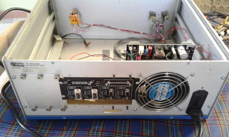 The Geckodrive mounted on the back of the
original controller box for the CNC table.
The Geckodrive mounted on the back of the
original controller box for the CNC table.
In 1990 the whole box was choc full of electronics to do the same job.
I
wasn't confident
of getting it to work as I couldn't get info on it, and anyway it only
had
two stepper
motor drives and I would need at least three. (The Gecko has four.) Now
I'm just
using the box's power supply with its on-off switch and emergency stop
button.
(and the fan... that loud fan has got to go!)
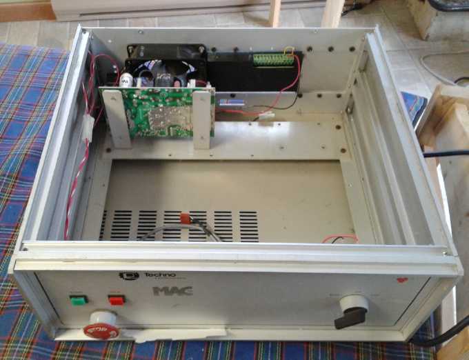 Front View
Then I reached the part about "using your software"
to step the motors and found that LinuxCNC was a 1.1 gigabyte
download. Oops. With my internet, that put an end to that for the time
being. On the 23rd I went to town to the library to use the WIFI and
try to download some short version, but I
spent much of that day and the next in frustration unable to get
anything I'd downloaded to work.
Later I phoned a friend in Victoria, Jim Lawrence. He
downloaded the
1.1 gigabyte disk image (in a minute and a half!) and sent it to me on
a DVD, which arrived August 3rd. I look forward to
getting the software, the CNC table and (at least) the CNC router to
work. Getting the
plasma cutter going (to do steel motor rotors and make equipment for
recycling plastic) will need additional work - a separate project. (Oh
boy, another project!)
More Things
In the meantime I did battery experiments. Doing the
batteries is a given. The osmium doped film and agar seems able to make
'everlasting' zinc electrodes, so in principle I seem to have
everything needed for nickel-zinc or manganese-zinc "prismatic cell"
batteries, with zinc sheet and plastic shelled Ni/Mn electrodes simply
stacked in a row filling the cell end to end. These would be "liquid
filled" but would require only a small amount of liquid.
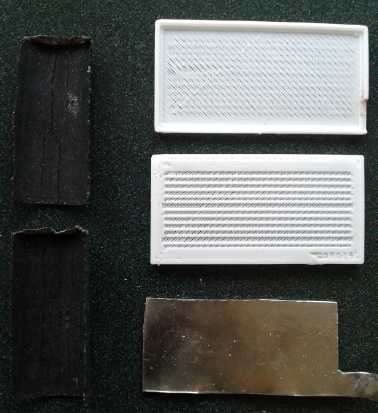 L: Sheet Zinc Electrode with "fluffy" zinc
electroplating giving it high surface area per volume for high
amp-hours. ("full size")
L: Sheet Zinc Electrode with "fluffy" zinc
electroplating giving it high surface area per volume for high
amp-hours. ("full size")
R: 3D printed Porous Plastic Electrode Shell to encase positive oxide
electrodes. ("test size" shell/electrode bits)
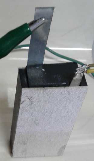 Test cell in use. It didn't look much different
from test "A" to "Z", but the things inside
definitely got better!
By the end of the month I had the makings of what should
be an "everlasting" zinc electrode with good performance, and "porous"
plastic shells for positive electrodes. The detailed writeup on all
this under Electricity Storage is about 1/2 of this newsletter,
which may be the longest one yet.
Of special note in this connection, Jim Harrington sent me
a link to a Canadian battery design challenge. It looks much more
promising than NRC's IRAP offerings. Instead of asking you to supply
over half of the money yourself in order to qualify for funding with
many strings attached (why bother?), it was sponsored by multiple
organizations who seemed more interested in getting better batteries
developed and made in Canada than in delving into every petty detail
about exactly what the future is expected to hold. (The future is
always changing as it unfolds, as even the last couple of months of
battery development in these newsletters abundantly discloses.) There
is more than one "prize" for promising sounding projects. If this
project doesn't sound promising at this point, I don't know what would.
The "up to" amount of each prize, apparently intended for
research, should be enough to start some small Everlasting Ni-Zn
battery factory -- and up the pace of more of my other research as
well. The grand prize of a million dollars to be awarded later would be
enough to expand on that factory and perhaps move it to a more central
location than "the edge of the world".
And I worked out some of the basic details for a unipolar
BLDC motor for an EV (etc): configuration, size, PM assist, coil
sequencing and rotor magnet sensing, and a new "resonant drive" system
to replace PWM for driving the coils. (More is under Electric
Transport.)
 And I thought I might manage to do the variable torque
converter
in less than geologic time if I could contrive to use the same
basic "experimental transmission box" for the Chevy Sprint that has
housed all such experiments, and fit everything in using all the
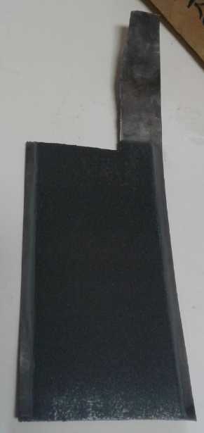
existing parts including the 'forklift' drive motor. I cut a new steel
plate to
mount the motor on. I took out the motor and transmission to see what
could be fitted. The motor wouldn't fit the way I had hoped, but I
figured out another configuration (the second of two possibilities that
looked good to me) that should work equally or almost as well.
I'll do my very best to make the whole thing sturdy enough not to bust
or slip instead of moving the car. (In fact, for once I think I'll do a
drawing first, to make sure everything actually fits exactly where I
vaguely expect it to, and to know exactly how to make each part.) (more
under Electric Transport)
And I thought I might manage to do the variable torque
converter
in less than geologic time if I could contrive to use the same
basic "experimental transmission box" for the Chevy Sprint that has
housed all such experiments, and fit everything in using all the
existing parts including the 'forklift' drive motor. I cut a new steel
plate to
mount the motor on. I took out the motor and transmission to see what
could be fitted. The motor wouldn't fit the way I had hoped, but I
figured out another configuration (the second of two possibilities that
looked good to me) that should work equally or almost as well.
I'll do my very best to make the whole thing sturdy enough not to bust
or slip instead of moving the car. (In fact, for once I think I'll do a
drawing first, to make sure everything actually fits exactly where I
vaguely expect it to, and to know exactly how to make each part.) (more
under Electric Transport)
![[pitcher]](GEV-Sparred-Front.jpg) I
didn't need any special new insights to continue (at glacial pace) the
radio controlled model for the ground effect vehicle. But it did occur
to me that if the ducted fans were in-line with the wing, that they
would have no tendency to push the nose down or need to be angled to
where they would be less efficient. So I re-made a couple
of longer,
'streamlined' spars so I could mount them solidly at the sides. They
should still be above the water there. (more under Electric
Transport)
I
didn't need any special new insights to continue (at glacial pace) the
radio controlled model for the ground effect vehicle. But it did occur
to me that if the ducted fans were in-line with the wing, that they
would have no tendency to push the nose down or need to be angled to
where they would be less efficient. So I re-made a couple
of longer,
'streamlined' spars so I could mount them solidly at the sides. They
should still be above the water there. (more under Electric
Transport)
And I continued to monitor and record the performance of
my electric solar panel system. It has been cutting 1/3 or more off my
electricity bill (which is pretty good considering it includes the cost
of driving my electric car all over the place). Even with a month of
nothing but clouds and overcast it put out about 55% of what it would
have in full sunlight, which makes such installations worthwhile at
today's solar equipment prices. I look forward sometime to being able
to store a couple of days worth of electricity in the new batteries.
By the end of the month I had some lengthy project reports
and a ton of pictures on my cellphone (camera) all to be edited and put
together, and I could see this newsletter wasn't going to be out in a
day or two. And there seemed to be one thing or another taking up much
of each of the first few days in August, too.
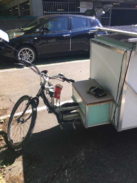
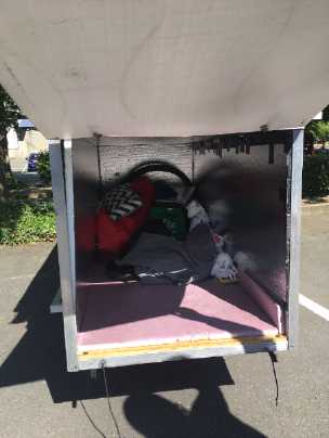
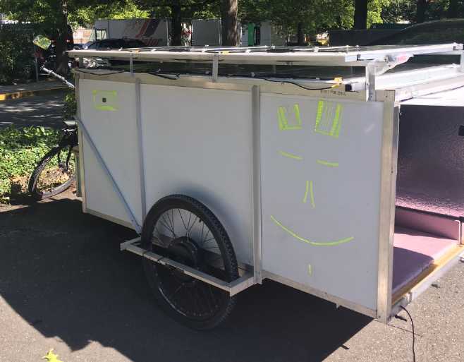
The Covered Wagon: E-Bike
My friend Tom Sawyer sent me pictures of a three wheeled
solar electric cycle he ran across. He said it was made by a homeless
person in Vancouver. If so the guy has a lot of talent, imagination,
drive and for sure someplace to work. It would be long enough to sleep
in (it seems to be insulated), and assuming a reasonable battery
capacity the 600 watts of solar panels that unfold would allow
considerable daily travel distance with (two?) typical e-bike motors of
500+ watts, especially as it would continue to charge at 300 watts
while riding. I imagine as long as one can afford to eat, one could get
to most anywhere, slowly but almost for free, with this unit. (Tom's
pinstriped electric Nissan Leaf with "Tesla" logos is in the
background.)
Donation
Someone sent me a very generous donation in July. I've
been
meaning to ask if he wanted his name and or the amount in the
newsletter, but somehow I didn't get to it. He said he has been reading
TE News for years with interest, and has made use of the ideas of
ilmenite for magnetic circuits and molded
polypropylene-epoxy composite material. Thank you
again, it is much appreciated!
In Passing
(Miscellaneous topics, editorial comments & opinionated rants)
Stop Colds Fast
Ever wake up and feel that unpleasant sensation at the
back of your throat that says you're getting a cold? I used to feel
helpless, knowing that it was taking hold and that in a few hours
it would spread and I'd be stuck with it, perhaps for weeks, until it
decided to leave.
Then I found a secret weapon: orange juice. by itself,
with no other food or drink. I woke up and had that nasty "cold
starting" feeling in the early morning hours of the 27th. I thought,
"Uh-oh! Surely this
has progressed too far to be stopped?" But I got up and rummaged
through the freezer and finally found a small container of orange juice
I had frozen, probably 3 years ago. (At the bottom, at the back. I knew
it was there somewhere! I split big containers of OJ into small ones so
I can use some and save the rest. Somehow I had stopped drinking it as
a regular drink, so the last couple had been just sitting in the
freezer. BTW this freezer is around -25° C -- that keeps things
much better for much longer than say -15°.)
I put the bottle into a larger container of hot tap water
so some would thaw quickly. I took that into my bedroom and managed to
get a couple of swigs before I lay down, and another couple before I
got to sleep again. Drinking too much too quickly isn't good anyway.
And I took the juice bottle out of the warm water. In the morning there
was no sign of a cold. I poured the thawed juice into a glass for
breakfast, but most of it was still frozen and I put it back in the
freezer for next time. When there's no more, I'll buy another bottle
and freeze it in smaller containers again, just for this purpose.
Something related that many aren't aware of (but may be
subconsciously aware of through experience of colds and flus): your
digestive system wants to do somewhat different things with alkali
reacting foods than with acid reacting foods. Citrus fruits don't go
well with starches, and they especially don't go well with milk
products. The digestive system can't optimally handle both at once, and
the environment is more conducive to viruses. Drinking fruit juice,
especially orange juice, with milk (eg, with cereal) is a ticket
to getting colds and flus. They're all good, but not together. Juice
and milk should be spaced hours apart.
[The source for this information is (if I remember the title right)
"The Edgar Cayce Handbook for Health Through Drugless Therapy" by Dr.
Harold J. Reilly (or was it Riley?) who Cayce referred a lot a patients
to. I read it decades ago. I can vouch that most any of the things I've
tried in it work. I seem to have lost it in my house move.]
Quinoa
Bread...
Mmm!
On the one hand I had been
baking my own whole wheat bread in a bread machine. On the other, in
spite of finding a better way it was a bit heavy and dense. ("knead
dough" cycle and then "bake only" cycle works better than "whole wheat
bread cycle", which makes it extra heavy and low rising.) Then on the
other hand, I had a big sack of quinoa I bought at a health food store
in Victoria over two years ago when I lived there. And again on the
other hand, I also had a couple of liters of quinoa that I grew myself
last year. (Mentioned in TE News #...123-125?)
I had used quinoa in bread. But it was grainy and not much
of an addition. Why wasn't there quinoa flour?
There's a lot of bitter stuff, little bits of chaff, in
with the home-grown quinoa. That's how it protects itself from being
eaten by bugs. (The store bought is all nicely cleaned.) It was
said to just rinse it in a collander under the tap, but that just
didn't work. I put some in a small mixing bowl, got a hair dryer, took
it out on the porch, and blew the hair dryer into the bowl. Shake the
bowl as you blow. When you have it right, most of the bitter and
lighter chuff comes out. Bingo!
Some is in clumps that still have some seeds in them. To
get those, rub a bunch of it between your palms, dropping it into the
mixing bowl. That breaks it up and then the chaff can be blown out
without the seeds.
So I took 1/2 cup of that and ground it in the coffee
grinder. Then I did the same with 1/2 cup of the store-bought quinoa.
The store bought ground finer, easier. The home-grown was somewhat of
"quinoa meal" while the store bought was definitely "quinoa flour".
(They may have been different varieties?)
Then I made bread as usual except using 3 cups of whole
wheat flour and 1 cup of quinoa flour instead of 4 of the wheat
flour. It rose to the lid of the breadmaker. It was delicious! The
texture was ideal and the flavor was great! 100% whole wheat flour is
now "out". 25% quinoa flour is "in". Now I'll seriously be using up the
quinoa instead of just a bit now and then. I may actually finish it all
some day. ...I bet it would be great
in pie crust! - a bit of a "graham wafer"-like effect? (Yup, it's quite
nice. Mmm, delicious pie from thimbleberries picked along the edge of
the highway! You wouldn't want to do that near a very busy highway, but
this is Haida Gwaii.)
It's great that 1/8 of the makings (potentially 1/4) of
the best bread came
from a small patch in my own garden. It seems pretty impractical to
grow
wheat, although I did grow a little once along with a few oats, and
this summer I have a small patch of barley. As well as corn, which just
might produce a few palatable ears. Some "volunteer" quinoas in the
barley patch (last year's quinoa patch) are growing well. (They're not
in a greenhouse, but the main garden is along the south wall of the
house, so it's a bit warmer and calmer than out in the open. Growing a
garden here this cloudy, cool July reminded me I'm not so far south of
Alaska.)
Another
Hair
Loss
Preventative
Using a brush on the scalp
instead of a comb didn't seem to be the whole answer. At the top at the
back, it gradually started getting thinner again anyway, and then I
realized I had lost some all along the top, too. Hardly noticeable
without looking carefully - I'm sure baldness creeps up on people that
way. I saw some "Rogaine" in the drug store and on impulse I bought
some. There was some patented ingredient, but I looked and it seemed
the main constituents were ethyl alcohol and propylene glycol. I
thought, "Wow! They've sure found a good way to sell alcohol and
antifreeze for a really high price!"
So I started looking on the web, and some clues seemed to
indicate that putting ethyl alcohol on your head is a very good way to
help prevent hair loss. Not just a little bit on the thinning patch as
Rogaine recommends, but over the whole scalp. In my enthusiasm and
experimentative nature I started spraying ethyl rubbing alcohol on
daily. (The squirter from the Rogaine fit on the alcohol bottle - the
one real benefit to the Rogaine besides triggering the search for
information.) But that must have been seriously overdosing - it's how I
gave myself shingles.
Maybe once or twice a month may be about right. The
ostensible reason for it is that it seems a primary cause of hair loss
is the hair follicles going "dormant". The reason for that is lack of
blood flow in the scalp. (That's why the stimulation of a brush helps.)
The reason for the poor blood flow is more or less continual
vaso-constriction because of cold - the sort of cool conditions many of
us in northern climes get used to all winter. (Hmm, how prevalent is
baldness in the tropics?)
Most people don't wear hats any more. Is your house warm?
Do you go around in the cool to cold all day? Is your bedroom cold at
night too? What part of your head is against the warm pillow? What part
goes bald?
Alcohol is a vaso-dilator when drunk. Apparently it
dilates the blood
vessels as well or better if sprayed directly on the whole scalp.
But I have a suspicion that there may be more to it.
Perhaps some bacteria or something that get growing in the cold scalp
that are part of why the hair follicles quit working. Not the shingles
(which bacteria never go away entirely once you've had chicken pox),
but something that persists along those lines and spreads over the poor
circulation areas of the scalp. If that is the case, killing them off
once a month with alcohol may go much farther than expected to prevent
hair loss in the first place whether or not it restores lost hair. But
that's just my present theory. It may simply be periodic
vaso-dilation.
I can see one can't expect miracles once hair has been
lost. Hair isn't lost in day, either. But maybe, eventually, it will
get thicker again? (<= wishful thinking alert!)
Small
Thots
* The whole world is fully populated (and then some). Very large
families have had their purpose, but may now be considered immoral.
Even 3 child families will continue to grow the population, albeit at a
much slower rate than with so many couples, so often in poor
circumstances, having
5 or more children.
The best and most effective aid more developed
nations could send to the "third world" is free birth control products,
freely proffered but with the notice "We can't take any more of your
ever-growing crowds of
desperate refugees. However many kids you have, you'll have to house
them and feed them yourselves." There is now, too little and much too
late to stave off the coming disaster, the beginnings of a backlash
against large families and in favor of birth control in the world's
most crowded countries such as Bangladesh.
* How the financial system is ruining everybody. Charles Hugh
Smith explained it all on Zerohedge.com one day in July. Central bank
prints money galore and lends it almost 'free' to other financial
institutions. They use it to speculate in investment assets. One of
these is real estate.
So say a mall cost 1 million dollars. The stores in it pay
1000 $/month rent. (just for nice round numbers.) Now an entity comes
along and buys it for 3 million - the free money for some is pushing
all
real estate prices up. Now they have to charge the stores 3000 $/m
because of their large mortgage. The stores have very little room to
raise prices in the declining market where the consumer isn't getting
proportionate increases in salary/income. Stores go out of business and
become empty. If the mall can't charge the
stores 3000, then the whole mall goes under. Here we have the makings
of the retail apocalypse which has been underway for a decade.
Smith explains it much better:
Main
Street Melancholy - Small Business On The Precipice
--
Authored
by Charles Hugh Smith via OfTwoMinds blog
-- Small businesses on the precipice need only one small shove to
go over the edge, and there won't be replacements filling the
fast-multiplying empty storefronts.
https://www.zerohedge.com/news/2019-07-30/main-street-small-business-precipice
* In the early to mid 1970s one could buy "Duralex" ("Made in France")
unbreakable glass drinking glasses. (I think they were associated with
the new "Corelle" by Corning dishware that is so much better than the
old thick, heavy, easily broken ceramic dishes. At least, they became
available at about the same time.) As with the Corelle dishes they were
very popular and everyone assumed they were here to stay.
I had (have) an 8 oz. Duralex glass that I somehow got
from my Mom. When I bought my house in 1977 I looked for some more in
the stores. I have a vague recollection of
at least one person saying then that they had looked all over but
hadn't been able to find any. I wanted the 8 oz glasses, but all I
could find was a set of four 6 oz. ones. I bought those "for now"...
but I have never again seen any Duralex glasses in any store. They were
the last ones.
You already know I'm the suspicious type... I think
someone of means deliberately got rid of them (one way or another) so
they could continue selling their regular easily broken glasses. But
that's only the same suspicion as other people voiced at the time.
Once you bought glasses that didn't break, you never needed any more,
so "they" got rid of them. I
have bought several sets of regular breakable glasses since then, since
6 oz is pretty small. Almost all of them are gone - bought, used and
then broken over the years. I still have three of the four Duralex I
bought in 1977 (I don't know where the other one went), and the 8 oz
one from my Mom (possibly bought 1971-1972?).
* Floating ice sheets extend variously around Antarctica. Variable
warmer sea currents are causing some of these to break up unexpectedly
fast. "Average" temperature doesn't count; it's the warmest points
causing the break-ups. New info
based on observing the collapsing Jakobshavn glacier in Greenland would
suggest that the ongoing breakup of the sea ice shelves destroys the
outer edge support and would cause the
mile to two miles thick on-land glaciers to start to collapse from the
shorelines. Since they are so thick they can't support their own weight
if the edge isn't supported, and so they will break up and flow faster
into the sea. As the Antarctic ice melt, thus far minor in global
terms,
increases, it would reach epic proportions. If it happens to the area
in the news some time back, this
would cause a very rapid global 11 foot sea level rise. It is probably
now just a matter of "when", and it didn't sound like it would be many
decades off. Say g'bye to most of the port facilities
and coastal cities around the globe. Say hello to hundreds of millions
of displaced and destitute refugees seeking higher ground. (I'm glad I
found this place, 25 feet above the present high tide mark! I could as
easily have taken one just above sea level and might then have wound up
in the refugee category in my lifetime.)
 Eagles feasting on a rotting sea lion carcass
on the beach out front.
Eagles feasting on a rotting sea lion carcass
on the beach out front.
Where it came from I have no idea. It was huge. Evidently somebody
thought it was a whale.
The first day I saw it someone had skinned the accessible part, but it
was too heavy to flip over.
 Bits of crystal(?) sponge have washed up all
over
the beach everywhere. Why?
Bits of crystal(?) sponge have washed up all
over
the beach everywhere. Why?
I've never seen more than the odd lone piece before.
I have only been here 2 years, so I don't know if this might be normal
every few years.
I hope it isn't yet another mass marine die-off - the end of the
world's only sponge reef!
ESD
(Eccentric Silliness Department)
* Conponent: That piece you got at such a great discount price, that
doesn't actually work when installed.
* Ah! I get it now! The glass labware item is called "beakers" because
they have "beaks" to pour out of. How mundane, ha ha! (How many decades
did that take me?)
* Az sumwun faymus wunss sed, "Hee iz uv smoll maend, hoo kan onlee
thingk ov wun wey tu spel u wurd."
* Rumor has it one should stay away from the bar in Epstein. You're
likely to catch something there. (...At first I thought it was just a
virus.)
* Do Linux computers have to be run in "sudo" mode to get permission to
play sudoku?
* Parachuting, like fine wine, is good 'til the last drop!
"in depth reports" for
each project are below. I hope they may be useful to anyone who wants
to get into a similar project, to glean ideas for how something
might be done, as well as things that might have been tried or thought
of... and even of how not to do something - why it didn't
work or proved impractical. Sometimes they set out inventive thoughts
almost as they occur - and are the actual organization and elaboration
in writing of those thoughts. They are thus partly a diary and are not
extensively proof-read for literary perfection, consistency and
completeness before
publication. I hope they add to the body of wisdom for other
researchers and developers to help them find more productive paths and
avoid potential pitfalls and dead ends.
Ground
Effect
Vehicle (first the R/C Model)
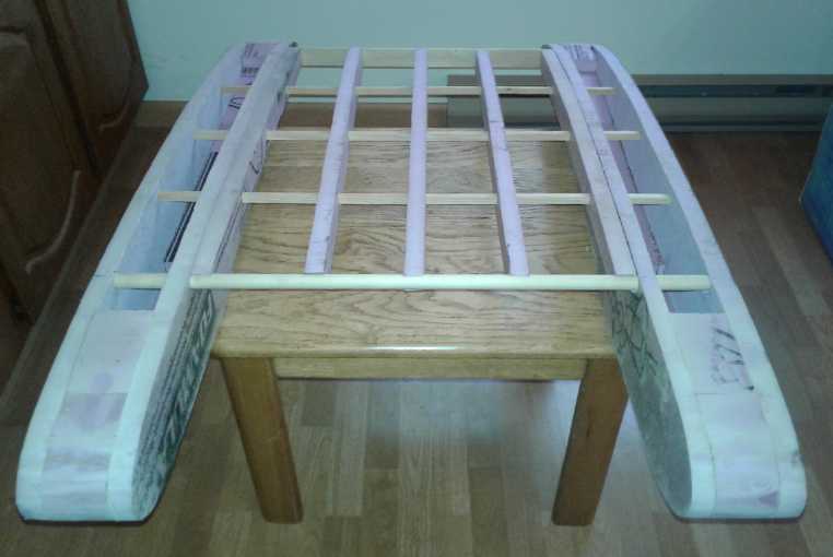
On the 9th I put the spars
and ribs together to form the wing, and did a bit of sanding. It
started to take on more form. Then I got onto other things.
On the 23rd
the motor controllers ("ESC"s) ordered in May finally arrived. Well,
they did
say up to 60 days delivery. There was two days to spare.
The motors had come with banana jacks on them. The
controllers came with bare wire and some bits of heatshrink to cover
the solder joins. I found a brass tube of the right diameter for the
jacks. I cut six 1 inch lengths and soldered three on the wires of one
controller, with some bigger, longer pieces of heatshrink to match.
Then I got out the radio controls and a 6 volt NiMH
battery tube to try one out. Everything worked fine. It blew a lot of
air. Then I tried 12 volts (10 NiMH AA cells tube). It blew a hurricane
and I could feel the fan want to move forward. Nothing ventured and all
that I put them both in series for 18 volts. Up to 22 volts is allowed.
This time it blew a hurricane at lowest throttle, and then sucked in
and ripped a nearby piece of paper. I think the craft will take off
with two of those on it.
(Ack, 1AM! How do I end up always staying up so late?)
---
Someone thought that the craft as configured would be
unstable, that it would "hobby horse" [in waves?]. Well, some
ground effect craft have done that. He mentioned that wings have their
center of lift at about 1/4 of the way from the front to the back. But
that was the point to to Ryland's special ground effect wing profile,
that the center of suction lift from the top would be much further
back. The wing is actually thicker toward the back than near the front.
It's a bit more like a wing "with its flaps down". Ryland says that the
compression lift from underneath, the ground effect lift, is more
toward the front. I'm not sure myself how pronounced that effect will
be.
Anyway we shall see! It may be that the batteries (the
heaviest
part) should be placed more toward the rear than the front, which would
also be unusual for an aircraft. But these questions are just more good
reasons for
making a model first. If there is anything like "hobby horsing"
instability that is hard to get rid of by physical design, my backup
plan is to take the "stealth fighter" technology route: a
microcontroller connected to inertial sensors and servo motors makes
instant microadjustments to the elevator to keep it on an even keel. If
that is done, it may be that the driver?/pilot?/captain? doesn't even
need to have an elevator control. After all, it isn't intended that the
craft fly up into the sky, only that it ride just above the wave crests.
Near the end of the month I decided the ducted fans should
go on the outside of the hulls, in line with the wing. That way they
would only be pulling/pushing forward, and not trying to push the nose
down as propellers above the wing do. That meant a couple of the spars
had to be made longer to mount them, as well as made streamlined.
Working on batteries as I was, I didn't get that done until the 30th.
GEV with the ducted fans placed outside, in
line with the wing
Finally to visualize what I have in mind, on the 31st I
pinned on a scrap of the paper-thin polypropylene cloth. (non-woven
"landscaping fabric") My intention is to epoxy this, as thinly as
possible so as to add very little weight. I expect this strong,
featherweight, cloth composite to be a modern version of the doped
canvas that early aircraft skins were made of.
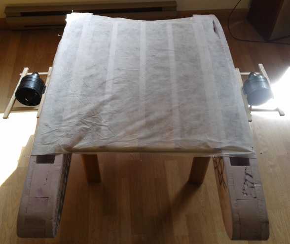
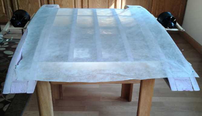
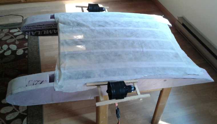 Three views with the motors set in place with
sticks
and a scrap of fabric pinned on for effect.
Three views with the motors set in place with
sticks
and a scrap of fabric pinned on for effect.
(The elevator that goes behind the wing at the very back isn't made
yet.)
---
In related news... I was thinking how the unipolar
BLDC motors
(next article down) would probably make great motors for the ducted
fans on the full size ground effect craft, except for their large
"pancake" diameter taking up so much room in the middle of the duct.
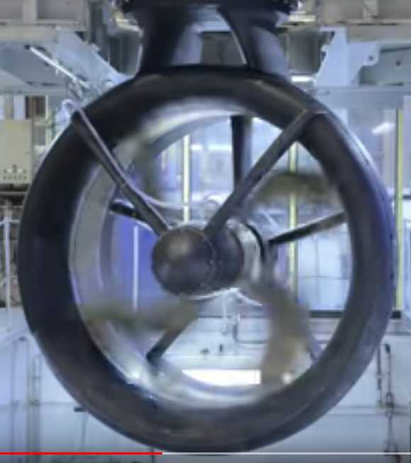
Then on
the 19th
I happened across a short video on youtube: Rolls-Royce | Permanent
Magnet Technology by Rolls-Royce. They were making PM / BLDC
motors
for marine use, as underwater ducted fans.
In their configuration the stator coils were on the inside
of a drum
around the outside: in the outer duct. The magnets were on a rotor rim
inside from that. Of course that configuration would be quite
applicable to the unipolar motor. The stator was the outside of the
duct, and the rotor with propeller was almost the whole inner diameter,
with no lump bigger than the bearings on the center shaft, and of
course a few stationary spokes. It seemed
ideal.
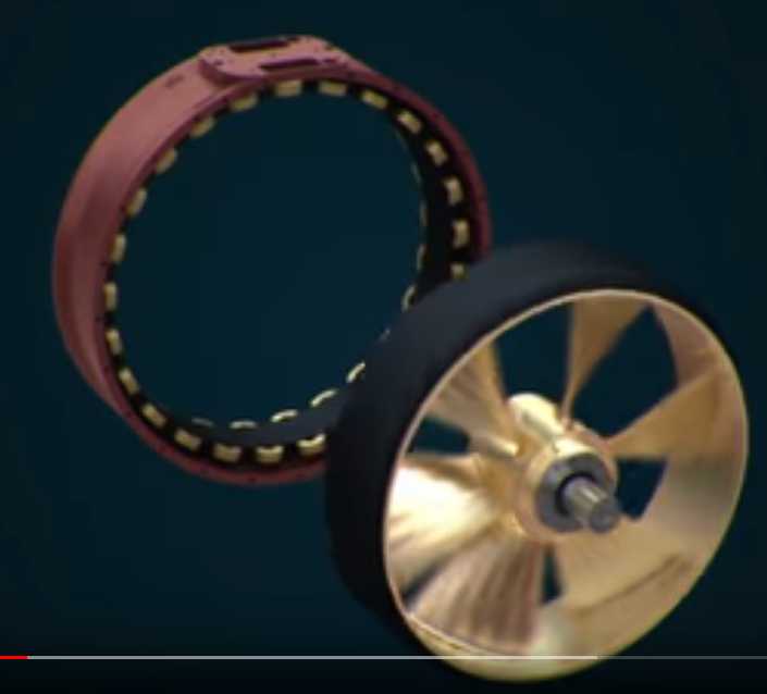 Rolls-Royce electric ducted fan motor for
marine use.
Rolls-Royce electric ducted fan motor for
marine use.
Outside: ring of stator coils. Inside: magnet rotor with fan.
 Stator ring and magnet motor rim form parts of
the duct,
Stator ring and magnet motor rim form parts of
the duct,
thus only a small center spindle is required to mount the rotor.
Somehow designing another whole new motor configuration
(and rather different than my others) wasn't quite what I had in mind
of when I thought of applying the (potential) new motor to the ground
effect vehicle.
Unipolar BLDC Motor & Motor Controller Design
![[drawing]](FigurinItOut-Roturz.jpg) On the 5th I decided to cut circles out of paper and draw
magnets and coils on them. Then I could actually rotate the "rotor" and
see which sets and sequences of coils (if any) would rotate it
consistently. I drew 8
magnets on the rotor and 12 coils on the stator. I wasn't sure that 12
and 8 would work. Rotating the rotor around the stator 1/3 of a coil at
a time disclosed that it was the same as 6 coils and 4 magnets,
doubled, and so of course it would work the same. (Duh!) What was
different was that being doubled, whatever coils were activated next to
each other was duplicated on the other side of the rotor, so the forces
were all symmetrical. Perfect!
On the 5th I decided to cut circles out of paper and draw
magnets and coils on them. Then I could actually rotate the "rotor" and
see which sets and sequences of coils (if any) would rotate it
consistently. I drew 8
magnets on the rotor and 12 coils on the stator. I wasn't sure that 12
and 8 would work. Rotating the rotor around the stator 1/3 of a coil at
a time disclosed that it was the same as 6 coils and 4 magnets,
doubled, and so of course it would work the same. (Duh!) What was
different was that being doubled, whatever coils were activated next to
each other was duplicated on the other side of the rotor, so the forces
were all symmetrical. Perfect!
It would seem that ideal conditions are: both the rotor
and stator have to have an even number of elements, and that there are
3 coils per 2 magnet poles. So, a multiple of 6 coils and 4 magnet
poles, but at least two sets so forces on the rotor are balanced
against the axle. Hence, 12 coils and 8 magnets.
So the next size up that would work so perfectly would be
18 coils and 12
magnets, which would be a triple set of 6 coils and 4 magnets, with
three sets of coils activated symmetrically 1/3 of the way
around the rotor from each other. Then 24 and 16 with four sets. I had
tried that, 24 coils with the "Electric Weel" and it was just too big
for me to make solid enough with my "Electric Hubcap" techniques. The
slightest off-angle on the axle bearings and the huge rotor would be
touching the coils at one point and too far away at the other side. I
would presume that the 18/12 size would likewise more than tax my
capabilities. It looked like the 12/8 size was thus IT! If other sizes
of motor were desired, they would have to also be made with 12 coils
and 8 magnet poles, with different size coils and magnets than the
sizes I
already have lots of.
I started with rotor magnet
"A" (north) approaching coil
"1" (north). This meant that also the opposite north magnet ("E") was
approaching
north coil 7. The other two north magnets ("C", "G") were approaching
south coils 4, 10. The coils that would drive the rotor clockwise from
this position were: 2 & 8 coming on, 3 & 9 already on, and 4
& 10 just
turning off.
Next I moved "A" just past "1". Now it was 1 & 7
coming on,
2 & 8 already on, and 3 & 9 turning off.
1/4 of a rotation thus needed this sequence of coils
driven:
2,8, 3,9
1,7, 2,8
12,6, 1,7
11,5, 12,6
10,4, 11,5
9,3, 10,4
1/4 of a rotation also brought the next set of north
magnets to coils 1,4,7 & 10, and so completed a magnetic cycle,
with four magnetic cycles to one physical rotation.
----
I then checked out the 3-4 (or "4-3") unipolar
configuration I had
conceived of in 2016, with the 8 magnet rotor and just 6 coils. Sure
enough, that could be made to run too, with the coil activation
sequence being the opposite direction to the 4 magnet, 6 coil
arrangement:
4,5
5,6
6,1
1,2
2,3
3,4 (and repeat)
Again with 12 coils (and 16 magnets) instead of 6 coils,
it would be bi-symmetrical with even forces around the rotor. But there
would be twice as many coil switchings for the same rotation. Since I
would be using 16 magnets anyway for the 8 magnet pole version, it
would be just a matter of mounting the same magnets one way or the
other:
NNSSNNSSNNSSNNSS or NSNSNSNSNSNSNSNS.
(Gosh, I actually have the unipolar Electric Caik with 6
coils and 8 magnet poles made in 2016 - asymmetrical forces
notwithstanding. That should work to test the required
6-phase motor controller that would be the same as for the 12 coils 16
magnets size. Then I can put on the regular rotor with 4 magnet poles
NNSSNNSS and try out both options. They would be sure to perform a
little differently. Might one have more torque than the other?)
Of course another new motor and controller is a very
considerable project. However, since I have already made very good
axial flux BLDC motors I am sure the unipolar one would be likewise an
excellent runner, and since the motor controller will doubtless be more
reliable, I am sure they would make a good set for an electric car. If
it wasn't for the large diameter - or maybe in spite of it - they could
also be a good set for a propeller drive - the ducted fans for the
ground effect vehicle or for a boat propeller. [See Ground Effect
Vehicle, above, for a new idea.]
And it would be great to be able to try out the "permanent
magnet assisted" coils idea, which just might bring a whole extra level
of performance per power used, perhaps somewhat akin to a heat pump
making a building warmer by an amount of energy greater than the amount
of energy supplied to pump it.
? Turns Per Coil
Now... How many winds per coil? In the Electric Hubcap there were 20 or
21 winds per coil with the three coils of the phase in series. Then
there were always 2 phases activated in series between ground and 36
volts (via the "Y" point). That's 120 (to 126) winds total. In this
unit just two coils are driven by each phase, which would suggest 60
turns per coil. But the currents will need to be higher because ony 1/3
of the coils are on at a time instead of 2/3. That might suggest using
30 turns per coil for a total of 60, which would mean #12 or #13 magnet
wire.
Which I don't have any of. Or perhaps double winding a #15 and a #16.
Then again, coils are inductors... how many winds for
double the current again? I have a feeling it's not a straight linear
relationship. I should probably be able to look it up on the web and
figure it out but my brain is rebelling. 30 turns sounds good.
Motor Sizing
 I laid
out 12 coils/cores on a table. I left a bit more
room between each two than in the original Electric Hubcap for
fatter wires and better
cooling - 78 mm instead of 73. When I had what seemed like a good size
circle, it appeared the magnet rotor should be about 350 mm diameter,
and the stator inner diameter then 370. (Make it 390 and have enough
room for the wiring for a change!) That seemed very substantially
larger than the 250/280 mm of the original Electric Hubcap. I
guess saying "huge" would be an overstatement. It would probably weigh
over 40 pounds. I don't suppose such a large rotor could take much over
2000 or 2200
RPM safely.
I laid
out 12 coils/cores on a table. I left a bit more
room between each two than in the original Electric Hubcap for
fatter wires and better
cooling - 78 mm instead of 73. When I had what seemed like a good size
circle, it appeared the magnet rotor should be about 350 mm diameter,
and the stator inner diameter then 370. (Make it 390 and have enough
room for the wiring for a change!) That seemed very substantially
larger than the 250/280 mm of the original Electric Hubcap. I
guess saying "huge" would be an overstatement. It would probably weigh
over 40 pounds. I don't suppose such a large rotor could take much over
2000 or 2200
RPM safely.
I would probably make the stator plate almost an inch
thick to be sure it didn't warp. Polypropylene-epoxy is quite light, so
thick ends don't add much weight. Later it occurred to me that "spoke"
ribs on
the outside might be the best way to go, with a thick bearing mount
place at the center. (The longer the short shaft is between end
bearings, the straighter it will be. and it will need to be very
straight for such a big platter.)
To review the figures: a 13
inch car wheel turns about 10
RPM for every kilometer per hour it's traveling. So to do 100 KmPH (63
MPH) the wheels are turning around 1000 RPM. I was counting on 3000 RPM
motor speed to be able to have two such motors, one on each front
wheel, to provide sufficient torque to get a car moving at 3 to 1
reduction yet do 100 KmPH on the highway, in case the variable
transmission didn't pan out. But at just 2200 RPM, the vehicle wouldn't
go much over 70 KmPH. I'd call that a success as a town vehicle, but
I'm not sure
other traffic on the highway would appreciate it. A reduction of only
2.2 to 1 to the wheels is asking for a lot of motor torque.
(...at least 35 foot-pounds each or better. At 3 to 1 it's 25 - still a
lot, but just a minimal 150 foot-pounds at the wheels.)
Now... about that 6-phase unipolar motor controller!
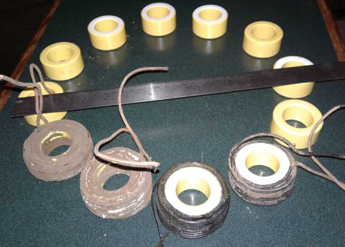
Permanent Magnet Assist - Magnet Fitting
I had found in 2016(?) that I could machine the iron
powder toroid cores on the lathe - I had done one. A typical washer for
a 1/2 inch
bolt could fit perfectly, flush with the top end of the core. The
purpose of the washer was as a "keeper" for a permanent magnet assist
cylinder magnet placed in the center of the toroid. But I had never
tried to fit one.
![[imidj]](CorWiPM.jpg) On the 11th I
dug out some 3/4 inch and 1 inch PVC water
pipe. The 1" one was too big for the core center and the magnet rattled
around loose in it. The 3/4" one telescoped inside the 1". It was too
small for the magnet and was very loose inside the core. I thought I
could probably shrink the 1" in the oven. Then I thought of cutting a
slit
in the 3/4". It could open up a bit to fit the magnet. It was too
stiff. I heated it to over 200°F in the oven and it was much more
compliant. I put it over the magnet. Then it looked a little too big
for the core, but I tried it anyway. It was a perfect, fairly tight
friction
fit. No looseness, no jamming anywhere! There was a gap where the slit
was, but that didn't matter.
On the 11th I
dug out some 3/4 inch and 1 inch PVC water
pipe. The 1" one was too big for the core center and the magnet rattled
around loose in it. The 3/4" one telescoped inside the 1". It was too
small for the magnet and was very loose inside the core. I thought I
could probably shrink the 1" in the oven. Then I thought of cutting a
slit
in the 3/4". It could open up a bit to fit the magnet. It was too
stiff. I heated it to over 200°F in the oven and it was much more
compliant. I put it over the magnet. Then it looked a little too big
for the core, but I tried it anyway. It was a perfect, fairly tight
friction
fit. No looseness, no jamming anywhere! There was a gap where the slit
was, but that didn't matter.
![[imidj]](CorForPMAssist.jpg) Then I put the washer on the end and
everything was just right. (The washer stuck out just a bit but the
depth of the machined space could easily be made a little deeper.) The
other end was still open, and predictably a second core was far more
attracted to
the open end than the closed end.
Then I put the washer on the end and
everything was just right. (The washer stuck out just a bit but the
depth of the machined space could easily be made a little deeper.) The
other end was still open, and predictably a second core was far more
attracted to
the open end than the closed end.
All was going just as according to theory! Now, if the
coil on the core was energized so as to have the same strength as the
magnet, the magnet and the coil should project their united magnetic
field at twice the strength the electricity being applied to the coil
alone would make. How could it not make more torque than just the coil
alone, yet without using more electrical energy?
My prime concern was that the magnet and the washer would
make for substantially higher iron losses than the miniscule losses of
the iron powder core and would thus warm the cores. The next day it
occurred to me I could machine the washer and magnet in at least a
little deeper, recessed in instead of flush with the top of the core.
That would help a little.
There was another takeaway from this little trial: in
order to allow for later addition of permanent magnets into the cores,
the 12 cores should be machined to
take the washers before winding them, and the stator plate
should be designed to lock down
the open end - i.e. the core center mounting "buttons" shouldn't be too
tall to accommodate the magnets. Easy to do and shouldn't make any
substantial performance difference if the magnets weren't put in, or if
they were put in and then removed. Simply adding the
magnets to the same cores in the same motor after initial tests, should
allow some very
fair performance comparisons!
Tuned Circuit Coil Drive
(20th) I came up with an idea for a new sort of coil driver,
especially appropriate to 'permanent
magnet assisted' technology. The permanent magnet assist, according to
sources I've run across, reduces currents at higher currents, but
doesn't do much at lower levels of magnetic flux. The assistance is
probably maximum
when the permanent magnet and the electromagnetic coil are magnetized
to the same strength. So even if lower power is needed from the motor,
it would pay to have the flux strength at a high level. So instead of
applying high frequency PWM to get less overall flux in the coil, short
bursts
of full strength coil activation would be used to gain high flux, with
rests between since full torque isn't needed. In other words, a very
slow PWM, perhaps measured in tens of hertz or even ones, instead of 16
KHz. (This would also eliminate what surely must be an [ultra]sonic
noise irritant.)
First I thought to put a capacitor in series with each
coil. That seemed ideal for turning on the coil and holding it on
for the resonant period. But then I couldn't see how to discharge the
capacitor when the coil was turned off.
So the tuned circuit would be created by putting a
capacitor in
parallel with the coil. Three B+ power line chokes (per 2016 unipolar
designs) for the six phases would be placed in series with the coils
so that the capacitor doesn't present an initial short circuit to the
driver. (I expect we can get away with 3 instead of 6 because an
oppositely timed coil is off when the active one is being
switched, and for a period before and after, so the one motor coil
isn't affected
by the switching of the other one.) In a coil, current rises with pulse
on time. In a
capacitor it drops. Thus the current, for the given resonant frequency
period, stays somewhat even instead of simply rising with time, and a
magnetically high level of flux is maintained at a relatively even
strength while the mosfet remains on.
When the mosfet switches off, the coil voltage continues
to be supplied by the capacitor. Decreasing flux continues to be
supplied until
the capacitor (and coil) voltage is exhausted.
No flyback diodes are needed in this configuration,
because the coil loses voltage "gradually" as the capacitor discharges
instead of being suddenly
switched off. Likewise, the main power line choke suddenly has a
voltage across it when any coil switches on, but as it is a
lower inductance this recovers
rapidly during the coil's on period and there is no significant
flyback effect. (I should check this out to make sure.) The saving of
energy usually wasted in flyback diodes
through their forward voltage drop is not insignificant, without
recourse to "active rectification" that means turning on mosfets that
just
might short across the power supply. (improved reliability.)
Based on the component values, the microcontroller (ie the
programmer writing the code)
must determine how long each resonant pulse should be, and the time
between pulses, and based on the "throttle" control and RPM, how many
pulses to apply and when, as a magnet passes between two coils.
Rotor Design
I decided that wrapping each magnet with PP
webbing/strapping is probably a waste of time. Maybe in a dirty
environment it protects the magnets better. But if the epoxy came
loose, the magnet might not fly out, but the rotor would still need
repair. I saw one youtuber (making a generator, was it?) who cast his
magnet rotor in epoxy, but he simply didn't fill it full, in order that
each magnet protruded and provided some "centrifugal fan" action for
cooling. That would surely be simpler and cleaner than the strapping.
Could the whole cast epoxy disk come loose from the steel
rotor? I had the thought that putting some smaller holes through the
rotor for the epoxy to put "roots" through would be a good improvement
to strength. Especially if they were drilled out on the back side with
a "V", so the plugs of epoxy would look like flat-head bolts. With
that, might I even dare push the max. up a couple of hundred RPM? 2400
or 2500 RPM sounds so much better than 2000 or 2200. OTOH 350 mm,
almost 14", is a big disk to spin! Also I'm thinking 1/4" steel rotor
might
be just as good as 5/16", and 20% lighter. (If only I had that plasma
cutter working... OTOH I could just have Victoria Waterjet do the rotor
and mail it to me. OTOH I have to get the CNC table working to make the
stator molds anyway.)
Activation Sequence
![[drawing]](FigurinItOut.jpg) (16th) In
3-phase motors, one uses 3 hall effect sensors each midway
between two coils to determine magnet positions - the rotation of the
rotor. Would the 6-phase controller need 6? Obviously one will be using
a microcontroller as the brain. There are no 6-phase motor controller
chips (much less unipolar ones). Three hall sensors do in fact provide
six different polarity combinations, and there are 6 phases. But with
unipolar coils it seemed lopsided - two sensors would be between N-S
coils and only one between a S-N pair. I put three hall sensor
positions between three coils on my paper 'motor' to figure it out.
Somehow it all worked out. Each of the six combos of three "norths" and
"souths" corresponded to one of the six coil activations. The
microcontroller could easily be programmed to pick the right ones. Only
three hall sensors are required.
(16th) In
3-phase motors, one uses 3 hall effect sensors each midway
between two coils to determine magnet positions - the rotation of the
rotor. Would the 6-phase controller need 6? Obviously one will be using
a microcontroller as the brain. There are no 6-phase motor controller
chips (much less unipolar ones). Three hall sensors do in fact provide
six different polarity combinations, and there are 6 phases. But with
unipolar coils it seemed lopsided - two sensors would be between N-S
coils and only one between a S-N pair. I put three hall sensor
positions between three coils on my paper 'motor' to figure it out.
Somehow it all worked out. Each of the six combos of three "norths" and
"souths" corresponded to one of the six coil activations. The
microcontroller could easily be programmed to pick the right ones. Only
three hall sensors are required.
Variable
Torque
Converter
Having groped around in the dark for a way to do this from
2009 to 2016, I gave it a rest after I moved to Haida Gwaii. I thought
maybe making reluctance motors that could freely do very high RPMs and
so not need a variable converter was a better answer - at least for me.
But
during June I had thought of a couple of fixed 3-speed gear designs,
and somehow started to realize that for a variable torque converter,
just two main components had to work together:
1. A three element gear set such as a planetary with one of the
elements being tied to the driving motor and the second one to the
output - the car
wheels or the differential. If the motor turned but the car didn't
move, the third gear had to spin.
2. The third gear's turning had to be controlled; obviously it couldn't
just free-spin. Controlling its turning would control the coupling
ratio between the other two. If it spun near its free-spinning speed,
the RPM reduction between the other two would be very great. If all
three elements spun together, the drive ratio (regardless of the number
of teeth on each) would be 1 to 1.
Furthermore:
3. If the control element ran around the same speed as the other two,
then the torque needed to adjust the control element would be as high
as that needed to move the car. The faster the control element spun,
the less the torque that would be needed to modify its speed. This was
driven home to me by the large control forces needed for the
experiments of 2016, driving one wheel and using the car's differential
itself as a 3-element variable torque converter gear set. A control
gear spinning 3 times as fast as the motor would need 1/3 the torque.
4. If the control element ran opposite to the motor, then the force
required to slow it would also try and slow the motor down. If the
control element ran the same direction as the motor but free-spun
faster, then the force needed to slow it down would add to the motor's
force instead. The losses incurred that way would be [I presume] lower.
I was
trying to accomplish that in the 2016 designs. But now I realize they
were needlessly complicated and less able to supply good results than
just (1) a planetary gear with ratios that would lend themselves to the
job, and (2) a centrifugal clutch (or a flat belt & pulleys
"clutch") to control the spin of the control element - both correctly
configured of course. (The way I was doing it before 2015, a clutch
that tried to halt the control gear entirely, was simply wasting
energy.)
It also seemed to me that the large centrifugal clutch I
made in 2016 (2015?) was an ideal means to couple the motor to the
control element. As the motor started the shoes would be retracted, and
the drum on the control gear would spin up freely. The car wouldn't
move. When the motor started imparting force to the drum via the shoes,
pressure would be put on the output gear and the car would want to move.
I found a planetary that looked about right - one I had
used before, early on. If the motor drove the planet gears assembly,
and the ring gear (connected to the car wheels) wasn't moving, the sun
gear (centrifugal
drum) would turn 2.8 times as fast and in the same direction. If the
sun gear was slowed toward the motor speed, the ring gear would have to
start turning and
speed up toward the motor speed - the car would move. If I have it
right, the torque to move the car would be (at most!) 1 / 2.8 times the
torque needed to slow the drum, or just over 1/3 as much. This would be
similar to having a 2.8:1 gear reduction. Multiply that by 3:1
reduction to the differential gear and it's the equivalent of 8.4:1
total reduction, which should be sufficient to start the car rolling
with a fairly small motor. The difference is that as the torque
requirement drops, so does the ratio. When all three gears are spinning
together with the shoes locked to the drum, the 1:1 ratio from the
variable section has dropped the overall ratio to 3:1, which will
prevent the motor from over-revving on the highway. If that loaded a
small motor too heavily, a 3.5:1 at the differential would give 9.8:1
overall reduction at low speed and still allow ~87.5 KmPH (instead of
~100).
Or if that wasn't good enough, I should look for a
suitable planetary gear with a higher ratio from the planets to the sun
gear, such as 4 or 5 to 1.
After
working
all that out on the night of the 5th, on the
6th I showed the gear and explained the concepts to a friend, and as I
did so, I realized it still wasn't the best arrangement. I was putting
the centrifugal shoes on the motor because that was the only part that
was surely driven at a known speed. But until the car started moving,
the sun gear would actually spin 2.8 times as fast as the motor. There
was the part to fling the shoes outward with maximum force! The drum
could be on the motor (planets assembly) and the shoes on the sun gear
instead.
And it appeared this configuration
would simplify construction. When laid out, it appeared that
the ring gear that had to drive the chain to the differential would be
off to the left of the 'experimental transmission box' entirely.
![[config 2]](TqCvtrConfig1.jpg) Still later I
realized that the drum could be either on the
motor or on the output (ring) gear with quite similar effect. Which was
better? At the start, if the drum was on the motor, it would be turning
1/3 of the speed of the centrifugal shoes, and in the same direction.
If it was on the output gear, it wouldn't be turning at all. Which way
made for higher torque to the output? Probably the latter? Either way,
as the shoes took more hold and the car accelerated, everything would
end up rotating at the same speed, 1 to 1 ratio.
Still later I
realized that the drum could be either on the
motor or on the output (ring) gear with quite similar effect. Which was
better? At the start, if the drum was on the motor, it would be turning
1/3 of the speed of the centrifugal shoes, and in the same direction.
If it was on the output gear, it wouldn't be turning at all. Which way
made for higher torque to the output? Probably the latter? Either way,
as the shoes took more hold and the car accelerated, everything would
end up rotating at the same speed, 1 to 1 ratio.
It looked like this might work well, but only if the motor
was on the port side of the box instead of the starbord. It looked
close, so at this point I wanted to fit the box into the car to see.
Just how
many ways were there to configure one planetary gear, anyway? It seemed
there were 6 possible ways to connect the 3-element gear to the 3
external components:
Motor
|
Differ-
ential
|
Ratio
Control
|
sun
|
ring
|
planets
|
sun
|
planets
|
ring
|
planets
|
ring
|
sun
|
planets
|
sun
|
ring
|
ring
|
planets
|
sun
|
ring
|
sun
|
planets
|
For each of those, one part of the centrifugal clutch
(either one) had to go to the ratio control, and the other part could
go to either the motor or to the output. So by picking which gear (x
3), and picking which element of the clutch went to which gear (x 2
again), that made 36 possible ways, each with its own advantages or
disadvantages. But putting the centrifugal shoes on the output
obviously won't work. And any configurations that cause reverse motion
of any of the elements is probably counterproductive. Without checking,
that's likely to be over half of them. Of the remainder, only one can
be optimum so the rest are relatively counterproductive by comparison.
I wonder how many counterproductive ways I've already
tried? The two options mentioned above the table seem likely to be the
best.
---
It looked like I could contrive to cludj everything
together mostly with parts and pieces I already had, perhaps
fabricating and welding up a couple more things. The next question was,
what to use for a motor? I had the Electric Hubcap, but the Kelly motor
controller was blown, and I had dismantled the surrounding parts and
used them for the forklift motor controller. So the simple thing would
be to use the forklift motor, already wired in to the car.
And... amid all the other fabulous projects, when on Earth
was I going to find time to put this together? But of course it was
easy to dig out the transmission box and various parts just to see how
they all fit together. When I did so on the 9th there seemed to be one
very big fly in the ointment: There seemed to be no way to arrange it
to fit the ring gear anywhere where a chain or belt or whatever from it
could turn the differential. The ring gear would be right outside the
box.
I turned the shaft around. It looked like it just might
work with the motor on the right instead fo the left. That seemed
preposterous, but measurements showed that it just might work. Maybe!
Just! To check it out I would have to disassemble the present (fixed
ratio) transmission, install the box, make careful measurements, and if
it could work, some new pieces for mounting things - the motor and a
steady bearing at the far end. There would sure be a lot of empty space
under the hood on the other side. One could easily place more batteries
there.
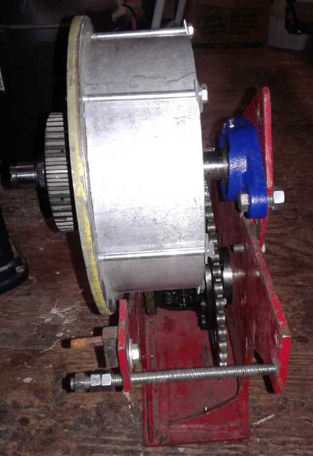
![[imidj]](TqCvrtConfig2.jpg) On the 22nd I took out the forklift motor and the
transmission, and put in the 'transmission experiments box'. It didn't
seem the motor could be fitted on the narrow side of the box. I
would have to rebuild the box as a sort of mirror image of itself. Or
would I? There were after all two similar configurations. My
plan was to place the centrifugal drum on the motor shaft. But if
instead I placed it on the output shaft, and reversed the car's
differential (chain sprocket on the other side), and made a couple of
new mounting plates with spacers, it
looked
like the motor could go in the larger space of the starboard side after
all. It might even be easier to mount things, and maybe even get a
bearing on to help stabilize the drum/ring/drive sprocket.
On the 22nd I took out the forklift motor and the
transmission, and put in the 'transmission experiments box'. It didn't
seem the motor could be fitted on the narrow side of the box. I
would have to rebuild the box as a sort of mirror image of itself. Or
would I? There were after all two similar configurations. My
plan was to place the centrifugal drum on the motor shaft. But if
instead I placed it on the output shaft, and reversed the car's
differential (chain sprocket on the other side), and made a couple of
new mounting plates with spacers, it
looked
like the motor could go in the larger space of the starboard side after
all. It might even be easier to mount things, and maybe even get a
bearing on to help stabilize the drum/ring/drive sprocket.
Finally on August 4th,
editing this newsletter, I looked at the first photo again. If the drum
was shifted way over to the right by making an offset mounting for the
steady bearing and maybe cutting a bit of a dish into the top of the
right side, the sprockets could line up and everything should fit that
way. I went out to the car where I had already set 'the box' in place
and checked it out. It looked like the drum could just clear everything
if it was all done just right. That should actually be the most
practical. (I couldn't place it there to take a photo without making
changes.)
---
In any event, (way premature of course) for something
besides a prototype I might look at something with larger
plastic gears that don't need to be immersed in oil, since it would be
at least difficult if not impossible to seal oil into a regular
planetary with
the external clutch components attached to it.
 The "all spur gears" differential or planetary gear
might be a good choice for that. I had come up with that (derived from
a sketch in Wikipedia) in October 2016 - the last month before I got
involved in buying a house on Haida Gwaii and moving. I think the sizes
of all the gears could be adjusted to provide any desired ratios.
The "all spur gears" differential or planetary gear
might be a good choice for that. I had come up with that (derived from
a sketch in Wikipedia) in October 2016 - the last month before I got
involved in buying a house on Haida Gwaii and moving. I think the sizes
of all the gears could be adjusted to provide any desired ratios.
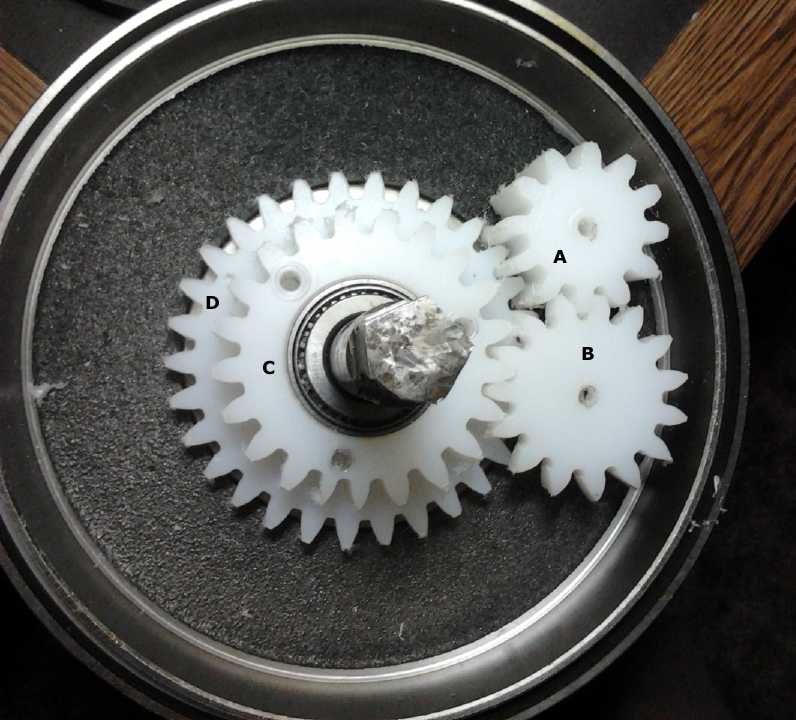
Then
one could probably drive gear "D" from the shaft going out the back
and attach the centrifugal shoes to it on the motor side of the drum.
The
outer drum (planets) could extend behind to engage the shoes,
all on the motor's side of the planetary. The output would then come
out the front on a shaft from "C" (attached to "C" and not with a
bearing there as shown, of course).
And then (after all that) since only a small center shaft
comes out each face, it could easily be sealed
to keep oil in for metal gears.
(I also note that gears "A" and "B" could be fixed on one
shaft, reducing three gear meshings to two and reversing the direction
of "C" -- albeit with more limitations on their relative sizes and
ratios. Gear "B" as
it is would be too small to reach "C" if it was on the same shaft as
"A".)
Other
"Green"
Electric Equipment Projects
36
V
DC
"Off
Grid"
Infrastructure
HAT36V-50A Plugs & Ceramic Sockets
On the 12th I finally got around to making a HAT 36V, 50
amp plug for the kitchen water tank. (If only so I could turn it off at
night without going out to the garage and flipping off the circuit
breaker.)
Before I wired the socket I plugged them in together and
everything was fine. But when I had wired the ceramic socket somehow
there was enough room in the 'minus' side that the 'hairpins' had
twisted around when I connected the wire, so the plug wouldn't plug in.
I twisted the socket around so the wire turned the 'hairpins' straight
again, and the plug went in. However, when it did a chunk broke off the
corner on the 'plus' side. The pressure on the 'hairpin' there from the
plug pin was too much for it.
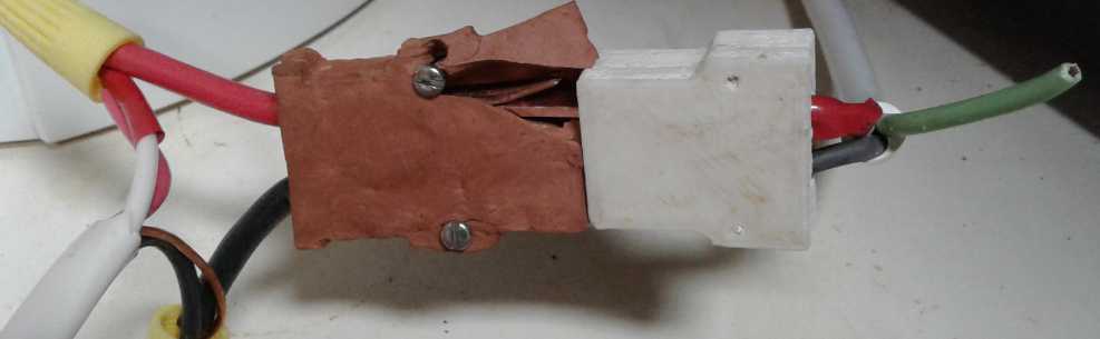 The ceramic socket cracked from the pressure
against the side when the 3D printed plastic plug was inserted.
The ceramic socket cracked from the pressure
against the side when the 3D printed plastic plug was inserted.
I taped it up and am using it. But it's not good advertising!
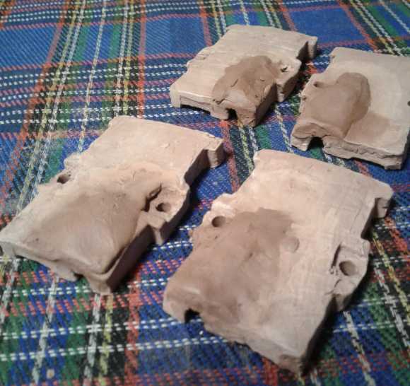 Apparently I either need to make them thicker or else out
of porcelain, which is considerably harder than ceramic. 'Cone 6'
porcelain is the top limit of what my poor little mini-kiln will do,
and it takes it four hours to get up to that temperature. But perhaps a
worse problem is that in this very hot firing porcelain shrinks more,
and tends to warp. That means (as I recall from making Supercorder
beaks) making a still more oversize mold and unreliable results.
Apparently I either need to make them thicker or else out
of porcelain, which is considerably harder than ceramic. 'Cone 6'
porcelain is the top limit of what my poor little mini-kiln will do,
and it takes it four hours to get up to that temperature. But perhaps a
worse problem is that in this very hot firing porcelain shrinks more,
and tends to warp. That means (as I recall from making Supercorder
beaks) making a still more oversize mold and unreliable results.
I thought I'd try making them from thicker ceramic first.
That still means designing and 3D printing a new mold. I tried sticking
some fresh clay on the unfired sockets at the weakest points, but it
didn't work. Predictably the new clay shrank as it dried and fell off.
At the Tlell fall fair on
August 4th I saw someone selling homemade pottery (nice selection!) and
thought he might have advice. As I explained about my broken ceramic,
he said "They're usually made out of porcelain." I guess that's my
answer. He insisted it didn't shrink so much and he usually expected
16%. My mold is 18% oversize.
I said it took 4 hours for my mini-kiln to get up to cone
6. He said "That's fast!" After a quick double-take I thought, "of
course it is, compared to heating up a larger kiln." A large kiln
firing can take 2 or 3 days. He offered to sell me a few pounds of
'cone 10' porcelain clay and fire them for me when he was doing a
firing.
First I'll get out my big block of 'cone 6' Dove Porcelain
and try that in my mini-kiln. (It's probably dried out and hard as a
brick, so I should find it and get onto re-hydrating it well in
advance.) If it warps or shrinks too much, I might take him up on his
offer and see if his clay and kiln work any better.
Handheld
Bandsaw
Sawmill
Notes
-
Update
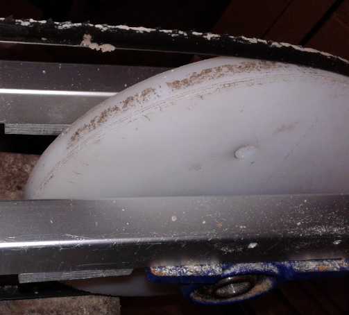 They say
spruce is a
tough wood to mill. It has "interwoven" grain that makes for tougher
cutting, plus it is pitchy and has hollow pockets full of sticky liquid
pitch that gum everything up. On the 7th I stopped cutting because of
slow cutting and worse, a lot of vibration - which turned out to be
lumps of sawdust glued even to the slippery UHMW wheels and to the
stainless steel band by pitch. I had to scrape them off.
They say
spruce is a
tough wood to mill. It has "interwoven" grain that makes for tougher
cutting, plus it is pitchy and has hollow pockets full of sticky liquid
pitch that gum everything up. On the 7th I stopped cutting because of
slow cutting and worse, a lot of vibration - which turned out to be
lumps of sawdust glued even to the slippery UHMW wheels and to the
stainless steel band by pitch. I had to scrape them off.
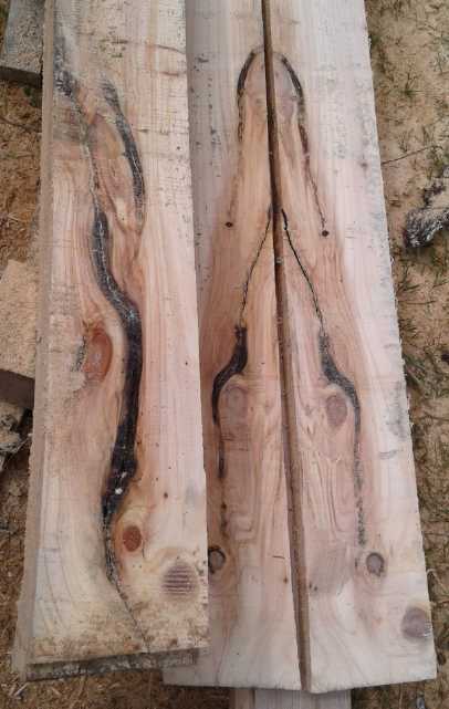 Cutting this piece was especially nasty. I went
through
Cutting this piece was especially nasty. I went
through
about 3 band sharpenings before I realized there must
be sand or something in the gummy voids. I finished it
up with the chainsaw mill.
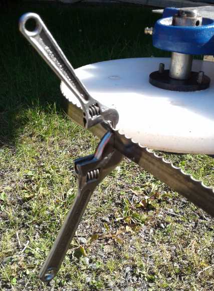 I 'set' the offset of the teeth with two
crescent wrenches.
I 'set' the offset of the teeth with two
crescent wrenches.
On the 9th I sharpened a band which I had already "set"
the teeth on on the 7th. The "set" made for straighter cutting, but I
still wasn't happy with the performance. Sharpened or not, all the
cutting seemed to take twice as long as I expected. I was cutting
1"x8"s, 10 feet long. and taking 7, 8, 9 minutes per board. At the
bottom, the last piece, the wood was only wide enough for a 1"x6", and
I trimmed 2" off one side with a skill saw (and chainsaw at the fat end
where it was too thick for the skillsaw). The 6" wide cut, literally,
went twice as fast as the 8" ones. ("3 minutes" according to my
cellphone, which is just another stupid "timer" that won't break time
down any finer than a minute. So, somewhere between 2 and 4 minutes.)
Doubtless a brand new band, or even a newer one, would have done better
on all cuts. But but 3/4 wide in 1/2 the time shows how gummy spruce
bogs everything down. I was happily cutting 10" and even 12" wide
boards in alder last September.
After setting the teeth one one band with two crescent
wrenches, I decided to make a pair of tools for the job. It was just
two pieces of small bar steel with slots in one end. No doubt I could
have gotten fancier -- How about a single item with a hinge? or a pair
of "crimping" pliers with the right bend built-in? I found that roughly
setting the teeth got the band cutting again, but then it made rough
cuts. Something that would set them all the same, evenly, would surely
be better.
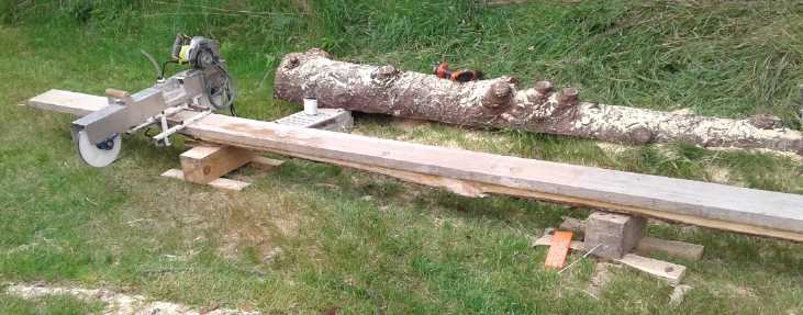 I made a couple of little stands with 6"x6"es
to put the
remainder of cants up on when they get thin.
I made a couple of little stands with 6"x6"es
to put the
remainder of cants up on when they get thin.
If you're pushing the saw forward with your legs (that turns out to be
the easiest way),
you don't want the cutting band down by your toes.
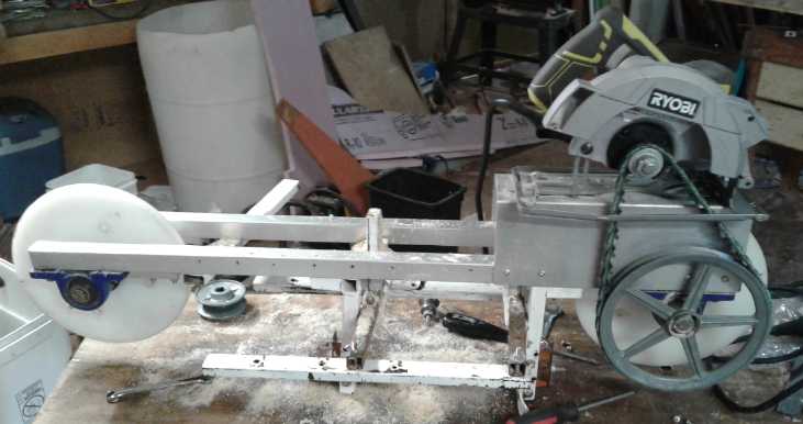 Here are a couple of pictures of the saw mostly
opened up on the bench to change the band.
Here are a couple of pictures of the saw mostly
opened up on the bench to change the band.
A couple of people have written me about building one, but I haven't
had time to draw up any instructions.
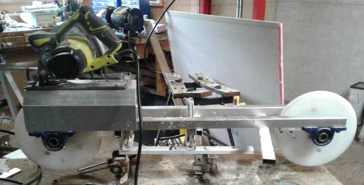
The key pieces are two 36" Alaska Mill rails,
pillow block or similar bearings, axles 10" UHMW wheels
(they shed sawdust etc), the cover pieces, and especially the double
"L" angle pieces that hold the self-
adjusting guide wheels et al, and the other pieces to hold and adjust
the rests that set the cutting height.
And the skillsaw, pulleys and V-belt (I used a link belt), of course.
The prospective builder will have to look in previous issues of TE News
for details on each component.
If the bearings were mounted more offset from the rails with the wheels
lower down, eg, with one inch
spacers, the top covers would be shorter, and there would be more
cutting height adjustment.
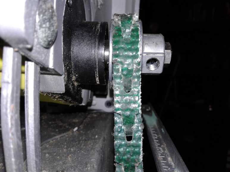 Latest change: 1 inch pulley replacing (larger)
adjustable pulley.
Latest change: 1 inch pulley replacing (larger)
adjustable pulley.
This pulley had a 1/2" center. I drilled it out on the lathe to 5/8"
for the saw spindle,
but not far enough so it could go on far enough to hit the stationary
bearing holder.
A longer "saw blade" bolt holds it on tightly.
I think the band slow-down is better but I wouldn't swear to it.
The "optimum" size might even depend on what wood is being cut.
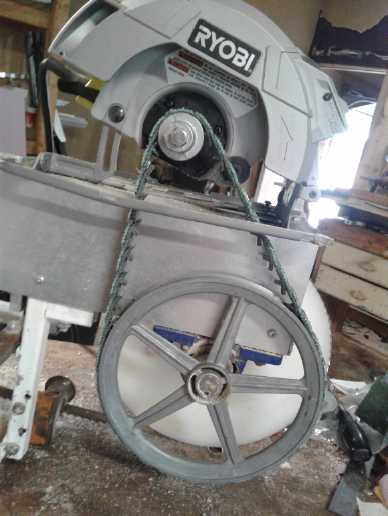 So now it's a 9 to 1 speed reduction.
One last thing... That tube with a sponge at the band for
cooling water... it's pretty primitive. I just saw someone on youtube
make a cooling water squirter by punching a small hole in the side of a
plastic pop bottle. Once he filled it, No water came out until he
loosened the lid of the bottle, then there was a thin stream out the
hole. When he tightened the lid again, it stopped. Wow, simple,
ingenious! I think I'll adopt that system for the saw!
Bathtub
Insert
Notes
While in the bath
(AM of 10th) I figured that if I was going to use up a spray foam can
to glue styrene foam and wood together and fill a few gaps for the
ground effect vehicle, and since you can't save the can very long once
you've started using it, and since also I had lots of scraps of styrene
foam, this would be the time if there ever was one to try out making a
bathtub insert. I dripped water to the kitchen and got a magnetic tape
measure off the fridge, a pencil and a handy chocolate bar wrapper
(half foil - more wet strength than paper) and came out with dimensions
on paper.
I also measured the water in my present bath. Sitting in
it, it was 5" deep - a pretty shallow bath. When I got out it was
3-1/2". (If I had lain down it would have been about 5-1/2" to 6"
deep.) I emptied the water into a pitcher and poured it down the sink.
I measured a little over 46 liters.
I came out with the inside dimensions. A person heavier than 160 pounds
might want to go larger, but I tried to leave extra everywhere. I
didn't want a tight fit at any point. I didn't make any compromises for
showers - pull the insert out and set it aside for a shower.
The tub had at least 53". I would shorten that just by the
thickness of the end walls. Those would be 2" foam, but I could cut an
inch away at the top-back since it sloped, so measure 54" max. outside
length. The back would slope inward at the bottom by 4", so (with the
top trim), 51" (and cut foot end at 45° to allow for the bathtub
curve up).
I figured 17" inside width for the first 22" from the back
end, then tapering to 14" at the 34" mark, and no less than 13" at the
foot end. I might have to curve or cut the side walls a bit. And I
might go just a bit narrower but slope the walls outward toward the top.
To cover my thighs (which I was never able to do in the
regular tub - it would have used the whole tank of hot water) needed a
9" depth. Since it would be inside the regular tub, I wasn't worried
about splashes. So 10" seemed like a good depth.
During the next bath I decided to make it all 2 inches
wider. If it was too narrow for comfort, there wouldn't be much I could
do about it. But if it seemed needlessly wide (wasting hot water), I
could glue an inch of foam on the inside on one or both sides to narrow
it.
Is it relevant to "green energy"? Well, it should save
energy (hot water) while providing a deeper bath. OTOH, I got rid of
the red spots on my legs with witch hazel, so my prime motivation for
wanting a deeper bath covering my thighs is gone. But the idea and the
plan is now in my head. I fervently hope this project will be as simple
and short as it looks, and not grow into some monster like so many of
them do!
By the end of the month I hadn't started using a spray
foam can, and I might not at all.
My
Solar
Power
System
Charge Controller Troubles
On the 8th I got up wondering which project I would work
on: batteries, ground effect craft, or maybe start putting together the
CNC table with the "Gecko drive" controller toward being able to do all
the things that would enable - especially including body section molds
for the new design of unipolar BLDC motor. And I had a cant of wood
outside waiting to be milled into 1"x8"s. I decided to start with the
house solar instead.
I had had a house guest for a few days (4th-7th) and we
used more hot water in the kitchen.
The MPT7210A charge controller continued to fail to meet the demand. It
would sit there putting out maybe 1.5 amps while the water heater was
drawing 6.5, and of course the batteries would discharge to supply
the load. It didn't seem to care that the voltage was dropping way
below the setpoint. There was lots of power coming from the panels
which it didn't try to use.
Notwithstanding the countless bells and
whistles, one can only question the thinking or lack of thought that
went into vital operational parts of the programming. (It rather smacks
of having been done by zealous and and academically inclined programmer
without much real-world experience in electrical/solar/battery
systems.) With more hot water use, 1.5 amps (or whatever) didn't
even recover the batteries in the shorter slack times when the water
heater
was off. So in the evening after suppertime dishes the batteries would
already be low, and then there was no more solar. I had to turn the hot
water off on all four nights to prevent the batteries from going too
low. (That doesn't say much for the old NiMH "D" cell batteries,
either, which should have held plenty of charge to compensate.)
If
I turned it off and on again the charge controller would wake up, rise
to
the occasion and start putting out 5, 6 or even 7.5 amps (the highest
I'd seen on this supposedly 10 amp unit). But I couldn't always be
there to babysit it! And I shouldn't have to.
So by the 8th I was pretty fed up. I removed the MPT7210A
(boost) and installed another PowMr (buck) charge controller. I put the
panels 2x2 in series to get the over 50 volts required by a buck
controller instead of having all 4 in parallel - which had also allowed
connecting to to the grid tie, in parallel with the charge controller,
if the DC system didn't need the power.
I saw from the last PowMr that if the hot water heater
drew 6 amps, within seconds it was putting 6 amps back in from the
solar panels to keep the battery voltage from dropping. That was the
way it should be!
The four panels were now at two different voltage levels
(~0-30 V and ~30-60 V). It would seem that the Y-Solar grid tie
'micro'inverters were isolated. (The case was grounded to the AC plug
ground pin, but no other terminal connected to any other on the
ohmmeter, and the
manual said the output was transformer isolated.) So if I got another
one, I should be able to put it on the two panels that were floating at
~~30-60 volts without issue and still have all four going to the grid
tie, but on two separate inverters. Unless I got another one to do that
(or brought one back from the trailer and put all four panels there on
the other one - easier!), I would lose two panels from the grid and
much of their power would go to waste.
With the batteries very low, when I turned on the solar
panel breaker, the PowMr immediately started putting out 10 amps, and
didn't drop below 8 (it was cloudy) until... actually, it seemed
determined to fry the batteries! One thing I don't like about the PowMr
charge controller is that it "auto-detects" whether the battery system
is 12, 24, 36 or 48 volts. Up to 40 volts it's supposed to detect "36"
- but 36 volt batteries of any type can charge to over 40 volts. So if
powered off and on again, it could decide that the 36 volt batteries it
itself had charged, were 48 volts. It seemed to have decided my
batteries were 48 volts regardless of them being a little under 40 on
its own meter. At almost 41 volts it still said "undervoltage" and
wouldn't turn the load circuit on, and it kept pumping in all the watts
it could get from the solar panels. I changed some settings and fiddled
around with it, turned it off and on a couple of times, and finally it
decided my system was 36 volts after all and then seemed to behave
itself. Disquieting!
I set the battery float charge voltage to 39.6 volts to be
easier on them than the 40 or 40.5 I had had earlier (max float for 30
NiMH in series would be 42.0) --
and to be under 40 volts at all times. Or rather, I set it to 13.2,
which it multiplies by 3 if the batteries are "36 volts". Later I
changed it to 13.1 (39.3 V) as it seemed to read a little low and so
charged them a little higher.
But setting
it to the same value is multiplied by 4 if it decides your system is
"48 volts". I do NOT like the charge controller "automatically"
deciding how many batteries you have. Might it do it again? If it was a
manual setting, you would only need to set it once anyway. You would never
want it to change by itself! There are few electrical system things I'm
more afraid of, especially having almost burned the house down with the
disastrous Suzuki Swift EV experiment in June 2017, than stupid charge
controllers obliviously (or is it deviously) trying, hour after hour,
to pump many times more juice into batteries than they can possibly
hold - or withstand. But I left it connected, and it did continue to
behave.
Once everything was running well, I made up another cord
with MC4 connectors to connect the panel on the lawn to the grid tie
with the other two 305 W panels. I cut the ends off an old 100 foot
extension cord I got at the waste disposal site. (The cable I had used
before I had made to use for the tugboat panels, and - the owner still
not having called me to finish the installation - I finally took the
cable, PWM/Lead-acid charge controllers et al, pretty much ready to
install, and dropped them off at his house when I was going up that
way. There's not much to it and he may finish it up himself.) Having
lots of length I moved the panel toward the east side of the house and
aimed it to the west to catch more afternoon and evening sun.
By the time everything was done, the day was pretty much
done too. So much for the little job to do before deciding what to do
for the day!
"Floating" Panel Voltage Grid Tie
(12th) I took one grid tie inverter from the trailer and
connected it to the other two of the series panels, whose outputs were
sitting at +30 and +60 volts (or +25/+50 or +35/+70 depending on load).
Sure enough, it worked. Nothing blew up. The inverters are isolated,
both input and output. Only the case is grounded, to the AC plug
ground. Now all 11 panels (with the one on the lawn) are grid tied
again. The 4 in the trailer are all back on one inverter. On all those
cloudy days there's not much difference. It will limit maximum
production on sunny days - which have been rare this summer.
Combining More Panels on One Grid Tie or Charge Controller?
The Y-solar grid tie inverters are "1000 watts" maximum.
In practice they seem to put out up to about 850. So it would seem
there's
not much point connecting more than 3 or at most 4 panels to one. But
what
happens if some panels are oriented east to get more the morning sun,
and others west for the afternoon/evening sun? The morning panels will
be putting out well below rated capacity in the evening and vice versa.
And neither ones will be delivering full power at noon. So one might
connect more panels - say 3 morning and 3 evening panels to the same
inverter or charge controller. Depending on facings and angles - and
the season - the
input to the unit would never be higher than with just 4 panels all
facing the same direction. But it would run more hours of the day. This
could perhaps accommodate a couple of or a few extra panels without
adding to infrastructure cost.
One could also potentially install extra panels just to
account for the dull days without buying more of the connecting
equipment. If one hooked up (say) five 305 watt panels to a 1000 watt
Y-Solar grid tie inverter instead of three, at 50% those 1530 rated
watts of panels would put out 765 watts, which is almost as much as the
inverter puts out at any time (~830W). So it would be more fully
utilized more of the time. It just wouldn't put out more on those less
common sunny days when the panels could give it more. (Actually, the
four panels I have may be a good compromise. ...or maybe six if three
face eastward for early morning sun and three face westward for the
late afternoon.)
(Somehow this seemed like a better idea in cloudy July
than after the first 5 fabulous sunny days of August! And after all the
Y-Solar grid ties are only 100-150$, and the PowMr charge controllers
equally cost effective.)
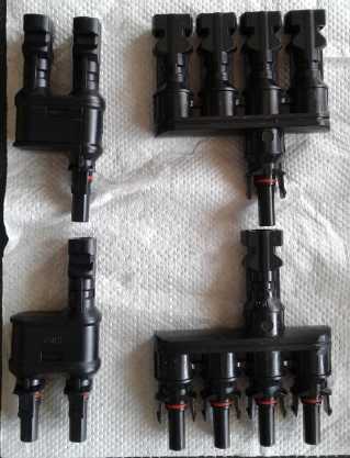 "MC4" connector combiners for combining 2, 3 or
4
"MC4" connector combiners for combining 2, 3 or
4
solar panels onto one grid tie or charge controller
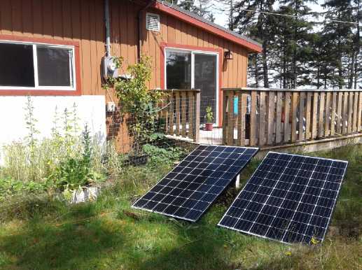 Westward facing solar panels on lawn - 2nd
panel added July 31st.
Westward facing solar panels on lawn - 2nd
panel added July 31st.
Once the tree shadows are off, they'll be making extra power later in
the day.
Hey, wait a minute... there were no tree shadows there a couple of
weeks ago!
In another week or so they'll be shading the garden by the house, too.
On the 31st I thought, "I have have solar panel combiner
plugs. A palette of panels sitting around. Why don't I add another
panel on the lawn on the same cord, also facing somewhat westward?" So
in the afternoon the house system collection went up to 8 panels. (The
#16 cord - an old #16 AWG 100' extension cord from the dump - got a bit
warm, but nothing like hot.) So one grid tie now has four 305 W Hanhwa
panels - same as the trailer roof. The other two ties each have just
two 250 watt panels, so they aren't being fully utilized, but with the
panels being 2+2 in series/parallel I can't combine them onto one and
have a spare tie left over to do more.
Solar Panel Post
 When I bought
the house there was an old 1980s Satellite TV dish on a post at the
edge of the trees. I soon took it off. This month I checked out how the
post was mounted
and with just a little digging I found it had a heavy square concrete
pad hidden in the grass. I
think I want to move that into the open somewhere and mount 2 or 4
solar panels on it. The top fixture is at latitude angle, the optimum
fixed solar panel angle. Ideally I would have two panels facing
eastward for morning sun and at least two facing westward for the
evening (which is
when I use the most electricity).
When I bought
the house there was an old 1980s Satellite TV dish on a post at the
edge of the trees. I soon took it off. This month I checked out how the
post was mounted
and with just a little digging I found it had a heavy square concrete
pad hidden in the grass. I
think I want to move that into the open somewhere and mount 2 or 4
solar panels on it. The top fixture is at latitude angle, the optimum
fixed solar panel angle. Ideally I would have two panels facing
eastward for morning sun and at least two facing westward for the
evening (which is
when I use the most electricity).
(Now I just need for my neighbor to come back from Lac La
Hache and move it for me with his big forklift.)
Month of July Log of Solar Power Generated [and grid power consumed]
The whole of July had only a couple of mornings or
afternoons of sunshine. Virtually the whole month was cloudy without a
single whole sunny day after the 6th. The afternoon of the 31st was
sunny, and then the first five days of August. It didn't make for good
garden growth or solar collection, but it did provide data about how
much collection one might expect in overcast weather, which proved to
be around 55% of full sun production for the month.
Notwithstanding, my power bills for March through July
2019 were only about 3/5ths of what they were the previous year. If
161$ for 2 months from mid March to mid May, and 117$ for mid May to
mid July sounds high to some, it must be remembered that that cost
includes the energy for my driving in the electric Leaf. Gasoline alone
for a gas car would have been more, and it wouldn't have cut the power
bill even in half.
(All
times are in PST: clock 48 minutes ahead of sun, not PDT which is an
hour and 48 minutes ahead.)
Date House solar KWH(Grid+DC), +Trailer Roof solar KWH - day
total KWH
made [power
co. meter readings] weather, usage...
June 30th 11.82+.68,508.53- 14.78 [laundry; 45Km, finish chj;
66860@22:00] Cloudy AM, Sunny PM
---
July1st 15.90+.63,512.76 - 8.94 [66866@21:30] Clouds, dim sun all
day.
Oops, grid tie on 1000 W panels was
turned off until afternoon. (shoodabin over 10 KWH!)
2nd 22.47+.78, 517.66 - 13.25 [66872@20:30] cloudy, dim sun. again.
(not chemtrails... I don't think?)
3rd 25.74+.66, 520.24 - 6.61 [65 Km, chj.car 3.8KW;
66886@21:00] cloudy
4th 32.14+.73, 525.44 - 12.32 [66897@21:30] Cloudy earlier AM,
Sunny PM
5th 39.79+.92, 532.47 - 15.60 [85 Km, car chj.@3.8KW;
66915@21:30] Sunny. Panel on lawn disconnected, 1KW panels feeding DC
only part of the day.
6th 42.90+1.12,538.36 - 10.12 [55 Km, chj@3.8KW; 66930@21:00] mostly
sunny. 1 KW panels went to DC only, Lawn panel disconnected. (This
doesn't make
the readings more consistent!)
7th 45.10+1.04,541.42 - 6.30 [66938@20:00; 55 Km,car chj.]
Overcast.
8th 47.65+.49, 544.24 - 5.86 [66949@12:30; 66950@20:30;
bath] Cast over again. Replaced DC charge controller MPT7210A with
PowMr. - now just 2 of the 4 250 W panels are grid-tied.
Reconnected 305 W panel on lawn.
9th 50.50+.51, 547.95 - 7.07 [66956@9:00; Milling with
Electric bandmill; 66958@20:30] Overcast.
10th 54.74+.57, 552.31 - 9.17 [66961@10:00; bath; laundry; 55Km,slow
chj; 66970@21:30] Overcast with a few less overcast spots
11th 57.67+.63, 554.96 - 6.21 [fini.car chj; 66976@20:30] Heavy
overcast. Where is summer?
12th 61.45+.55, 558.42 - 7.79 [85Km drv,fast chj.3.8KW; 66992@20:00]
Lighter Overcast. Got all panels grid tied again.
13th 68.49+.48, 563.71- 12.81 [bath; 66996@14:00; 55Km,slow chj]
Overcast, PM with sunny periods. WOW! 1570 watts from the house panels
alone when the sun came out. (while the panels were still cool.)
14th 73.72+.53, 567.69 - 9.74 [67003@14:00; 50Km,Fast chj car from 37%;
67014@19:30] Light overcast
15th 78.41+.48, 571.04 - 8.52 [67019@20:00] Overcast. Some rain.
16th 79.77+.60, 572.56 - 3.48 [60 Km drv, chj 3800W; 67036@19:00]
Clouds and rain. WOW, what a dull day! The PowMr couldn't get enough
power to keep the batteries up (the solar hot water heater used 600 WH)
with the grid tie inverters hogging it, and I had to turn one of them
off! (After going to all that work wiring it in - but partly just to
see if it would work with non-zero floating voltage level panels! But
then it stayed on on other days.)
17th 83.72+.66, 575.98 - 8.03 [BR heat(in July!?!); 67044@10:00;
67046@20:30]
18th 88.91+.49, 580.50- 10.20 [BR heat; 67052@20:00] Mixed sun (yay!)
and clouds (with chemtrails above)
19th 92.45+.41, 583.79 - 7.24 [67057@15:00; 85 Km,slow chj.car;
67062@20:00] Overcast
20th 96.03+.03, 588.70 - 8.52 [BRHeat; 67068@10:00; bath, some car
charging; 67075@21:00] Overcast.
21st 03.54+.76, 592.31 - 7.91 [Car full charge 3.8 KW; laundry;
67094@22:00] mostly overcast. The energy monitor in the garage 'froze
up' and I had to unplug/replug it to get it working again. That was in
the morning, but by no means first thing.
22nd 8.37+.60, 596.10 - 9.22 [oops, left BR heat on all day. But
it probably didn't come on; 67102@21:30] AM: Sunny with clouds and
jettrails (for a while I thought it just might be summer). PM: Overcast
and some rain.
23rd 14.01+.49, 600.46- 10.49 [55Km,part chj.@1500W; 67112@19:20]
clouds with sunny breaks
24th 19.28+.47, 604.62 - 9.90 [67122@21:30] AM: a bit of sun. PM:
Overcast, cold, wind and rain.
25th 21.16+.54, 606.23 - 4.03 [67128@21:00] overcast & cold.
I had to shut the 250W panels' grid ties off so the PowMr could get
enough to run the water heater & keep the batteries up.
26th 23.21+.62, 608.37 - 4.81 [85Km drv. 3.8KW chj.car;
67150@21:00] Clouds & rain.
27th 27.34+.45, 611.94 - 8.15 [55Km,start.chj.car@1500W;
67167@20:30] Mostly overcast.
28th 31.46+.54, 615.58 - 8.20 [finish Chj.car; 67173@20:30]
Clouds, a bit of sun.
29th 37.88+.35, 620.17- 12.36 [65Km,stt.car chj.@1500W; 67181@19:30]
Clouds with occasional sun.
30th 41.59+.62, 623.72 - 7.98 [finish car chj.; 67193@21:00]
31st 49.85+.53, 629.39 - 14.46 [67202@ 20:30; Br.Heat] Early: rain,
Most of day: Sun w. scattered clouds, very light haze, no jet trails.
---
August 1st 57.62+.53, 634.98 - 13.89 [67207@11:00; bath; 67208@21:00]
Mostly Sunny, no jet trails. Forgot I had turned 2 inverters off
previous evening, until late morning.
2nd 66.90+.44, 641.21 - 15.95 [67213@20:30] Sunny
3rd 75.19+.43, 646.98 - 14.49 [55Km,chj.car slow(oops, into
evening); 67222@20:30] Mostly sunny
4th 84.59+.52, 653.39 - 16.33 [55Km,car chj.@1500W; bath;
67233@20:00] Sunny, warm day for the Tlell Fall Fair!
5th 91.79+.45, 659.80 - 13.76 [finish car chj; 67240@21:30]
Sunny. Oops, left 2 grid ties turned off again. (Wouldabin ~16 KWH)
Daily-
KWH- # of Days (July)
Made
3.xx - 1
4.xx - 2
5.xx - 1
6.xx - 3
7.xx - 5
8.xx - 6
9.xx - 4
10.xx- 3
11.xx- 0
12.xx- 3
13.xx- 1
14.xx- 1
15.xx- 1
17.xx-
18.xx-
As there wasn't a single full sunny day in all of July,
the average value of "full-sunlight collection" in July is rather
speculative. The few sunny days in June were around 18 KWH. The best
sunny day in May, the 27th, was 16.96 (17 KWH by any other name.) In
early August (finally sunny) it only hit about 16 KWH, and that was
with the 12th panel connected. So perhaps it would be fair to say that
the average maximum that might have been expected in July (with 11
panels), had the days been sunny, would have been about 16.5 KWH.
Total power
generated in July was 273.98 KWH, divided by 31 days was 9.13 KWH/Day.
9.13/16.5 = .5535. So the overall collection in July, through all the
clouds and overcast
weather of the whole month, was nevertheless about 55% of
full-sunlight collection. It doesn't get much worse than "not one sunny
day all month". It's said that the cloudy west coast is the worst place
to install solar, but given the low prices of solar equipment these
days, it's worth while anyway. And if our electricity wasn't being
subsidized, it would be much more worth while and there would be solar
panels springing up everywhere. (Much of the power for this island is
made by diesel generators and the cost for generating that is said to
be 50¢/KWH, but we only pay around 12¢ like the rest of BC.)
And This July
was nothing like sunny July 2018. Collection would have been much
higher last year. The 31st mercifully had a lot of sun
and some warmth, and it was good to see figures of over 1400 watts
coming
from the six house roof collectors plus two on the
lawn (the second one placed just that day), instead of 400 or 800, or
even 200 on the dullest days. (And August has started out sunny. If the
sunshine keeps up, I might just get some corn by this fall!)
Monthly Tallies: Generated KWH [Power used from grid KWH] ("April 0" =
March 31)
March 1-31: 116.19 + ------ + 105.93 = 222.12 KWH [786 KWH]
April - 0-30: 136.87 + ------ + 121.97 = 258.84 KWH [608 KWH]
May - 0-31: 156.23 + ------ + 147.47 = 303.70 KWH [543 KWH] (11th
solar panel installed on 26th)
June - 0-30: 146.63 + 15.65 + 115.26 = 277.54 KWH [374 KWH] (36V, 250W
Hot Water Heater installed on 7th)
July - 0-31: 134.06 + 19.06 + 120.86 = 273.98 KWH [342 KWH]
5 month total: 1336.18 KWH made; [2653 KWH consumed from grid]
Power generated that went to the grid from my
ad-hoc arrangements was not subtracted from the utility meter readings
or otherwise accounted for. By the end of July I was looking at getting
& installing approved equipment to 'legitimize' my system. (A 1200
watt approved grid tie inverter I'm considering is over 500$. I paid a
bit less than that for all four 1000 watt Y-Solar grid tie inverters.
And the Y-Solars just plug in. That was actually their biggest
attraction and the reason I got them actually working. The 'proper' one
has to be 'installed' and fed to its own double circuit breaker in the
electrical panel.)
Electricity Storage (Batteries)
Dried Out Dry Cells
I had got the theory
about 3 years ago that the NiMH dry cells quit working because they had
become too dried out inside. And I thought that I should try throwing
them in water for a while before discarding them entirely. Having
opened one "dead" NiMH "D" dry cell and determined that it was indeed
quite dried
out inside except right near the middle, on the 6th I took a bunch of
the others from the garbage pail and threw them in a barrel of water,
about 3 feet deep.
A few hours in water didn't help. A few days didn't help. 2-1/2 weeks
didn't help. Maybe a long vertical pipe full of water, so that there
was some
pressure pushing the water into the cells? Or maybe once they wouldn't
charge, it was too late.
Anyway I'm very much souring on NiMH "D" dry cells for
high
capacity storage. The ones I'm using for my solar storage work, but
they hardly
seem to have 10 or 20% of their original rated capacity. Admittedly the
majority were somewhat abused in the Mazda RX7-EV and they're five
years old, and admittedly I'm not charging them to maximum "float"
voltage and capacity any more (trying to get them to last): 39.5 volts
rather than 42.0. (1.35 V/cell rather than 1.40) But dry cells in
charging and discharging I think just
gradually lose what little water they start with. I don't think my
drills with NiMH sub-C cells run as long as they did a couple of years
ago either. Neither does my 'netbook' with a lithium battery run even
half as long as when it was new 2-1/2 years ago.
For serious energy storage, better to make my own
batteries - and not dry cells!
Turquoise Battery Project: Ni-Zn or Mn-Zn in KOH ? or in KCl ?
![[imidj]](2019_02_DOE-Battery-Research-300x223.jpg) I
wondered what sort of cost
projections I would be facing to do Ni-Zn or Mn-Zn cells. Without
wanting to do anything like a detailed analysis, I found this chart of
"cost goals" on line, from the US DOE.
I
wondered what sort of cost
projections I would be facing to do Ni-Zn or Mn-Zn cells. Without
wanting to do anything like a detailed analysis, I found this chart of
"cost goals" on line, from the US DOE.
The "dissing" of Ni-MH big flooded cells has apparently
worked so well that they aren't even mentioned, notwithstanding what a
great success they were in the EV-1 et al. (Ovshinsky - and maybe
Jungner and Edison - must be groaning from Mansonia!)
Mn-Zn however has more energy per weight than Ni-MH and
the second lowest potential cost listed -- but it's only useful if the
zinc dendrite growth problem is solved. With my developments of June
and this month I believe it has been.
Ni-Zn has a higher voltage potential than Mn-Zn (1.7+ vs
1.4 or 1.5 depending on your criteria) and shouldn't cost much more the
way I'll be constructing cells, so the price per capacity may be about
the same, or perhaps even a little less with fewer cells needed to
attain a voltage. (Using nickel manganates will increase the current
and capacity per weight and size and cost, and I'll be using copper and
conductive carbon black in urethane conductive paint rather than more
costly nickel for current collector components.)
So my estimate would be that my batteries, if
"manufactured at scale", should come out in the cost ballpark
indicated, 50 $/KWH. And if they are also "everlasting", who would want
any of the other ones listed for most bulk storage uses?
Preparing a Zinc Alkaline Electrode
Here are microscope pictures of the zinc in the stages of
preparation as I did it on the
11th.
The first interesting change of procedure was to etch the
surface in hydrochloric acid instead of ferric chloride. With copper
one must add hydrogen peroxide to get a gradual reaction to copper
chloride
to take place. The zinc boiled vigorously from the instant it was
dipped into the acid. So I
only left it in for a second. (I knew there was a reason I put safety
glasses and a plastic glove on! Now, about that fume hood that any
self-respecting chemist would have...) Then I washed it off with
varsol. It was much harder getting the black color off than it was
after ferric chloride, and I didn't get it very clean.
I tried a second piece and left it in longer - 3 seconds.
I could feel it was getting warm fast. Did it look any different? It
was harder cleaning off the black off, so it probably had some deeper
recesses.
Surely the black color must be zinc chloride, ZnCl2? What
else could it be? But then why didn't it dissolve in water? Another
mystery!
Could there be such a thing as Cl-Zn-Zn-Cl , Zn2Cl2 ? Oh... It's most
probably zinc carbonate. First zinc oxide on the surface from the air,
then it gets a carbon dioxide from the air. 2 Zn + O2 => 2 ZnO ; ZnO
+ CO2 => ZnCO3 . Why is there so much after etching it? Is it
already there, just in unseen concentration until some of the pure Zn
is etched away? (Looked it up. Nope. ZnCO3 is translucent white
crystals, a zinc ore called "smithsonite". Still a mystery!)
Microscope
images of zinc surface
1. As-made, straight off the roll of "moss killer" zinc for roofs.
2. Scratched up with nylon scouring pad ("Scotchbrite") to clean and
make some surface convolutions.
3. Etched with hydrochloric acid (~1 second) and cleaned with varsol.
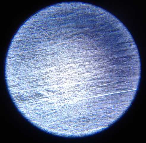
4. Etched 3 seconds & cleaned. (I think it was a little thinner - ?)
The "zincate" ion, sodium-zinc hydroxide, had made a
pretty good fuzzy plating on the zinc sheet. The video had mentioned
doing it with acid to get a smooth zinc sheet plating. I decided to try
in between - zinc as a chloride salt. And if I was next going to try
plating the zinc in a bath of zinc chloride, why worry about getting
the chloride off now? It was just more zinc to plate on - or in this
case, back on.
![[imidj]](ZnInHCl.jpg) First thing
was to make the zinc chloride bath. That was a
no-brainer: throw pieces of zinc into the hydrochloric acid until it
stopped devouring them. I poured 105 cc of acid into a 250 cc beaker
and dipped in a
piece of zinc. It was immediately a roiling boil and the piece got hot.
Hmm, an open window wasn't good enough. It took it outside. I dipped it
in a few seconds at a time, and soon the bottom of the piece was eaten
away. After a couple of those, I started cutting the zinc into very
small pieces and tossing them in, one or two at a time. Unquestionably
zinc has a lot of energy in it when it reacts. as does acid of course.
When it was headed for 20 grams of zinc dissolved, the reactions slowed
visibly. The 24th gram hardly bubbled and the bubbles were so tiny the
liquid turned 'milky'.
First thing
was to make the zinc chloride bath. That was a
no-brainer: throw pieces of zinc into the hydrochloric acid until it
stopped devouring them. I poured 105 cc of acid into a 250 cc beaker
and dipped in a
piece of zinc. It was immediately a roiling boil and the piece got hot.
Hmm, an open window wasn't good enough. It took it outside. I dipped it
in a few seconds at a time, and soon the bottom of the piece was eaten
away. After a couple of those, I started cutting the zinc into very
small pieces and tossing them in, one or two at a time. Unquestionably
zinc has a lot of energy in it when it reacts. as does acid of course.
When it was headed for 20 grams of zinc dissolved, the reactions slowed
visibly. The 24th gram hardly bubbled and the bubbles were so tiny the
liquid turned 'milky'.
![[imidj]](MakingZnCl.jpg) I had put a
big pail over it to dissuade any curious crows
or ravens. Every time I tipped it away I could see a cloud of hydrogen
gas come out. As things slowed down I put bigger chunks of zinc in, and
I went inside for a while. A while later gram 26-27 was floating on top
and still bubbling away slowly. It became apparent that there would be
no abrupt end to the reaction - it would just get slower and slower
before it petered out. I threw in a bit more, 3 little pieces making a
little over 30 grams of zinc - 25 theoretical amp-hours worth. Thin
slivers of it remained, and another chunk I threw in hardly seemed
touched. Finally pH rose to 2, and the reaction seemed to have stopped.
95 cc remained, so liquid lost in all the bubbling was maybe 10 cc, or
10% give or take a few.
I had put a
big pail over it to dissuade any curious crows
or ravens. Every time I tipped it away I could see a cloud of hydrogen
gas come out. As things slowed down I put bigger chunks of zinc in, and
I went inside for a while. A while later gram 26-27 was floating on top
and still bubbling away slowly. It became apparent that there would be
no abrupt end to the reaction - it would just get slower and slower
before it petered out. I threw in a bit more, 3 little pieces making a
little over 30 grams of zinc - 25 theoretical amp-hours worth. Thin
slivers of it remained, and another chunk I threw in hardly seemed
touched. Finally pH rose to 2, and the reaction seemed to have stopped.
95 cc remained, so liquid lost in all the bubbling was maybe 10 cc, or
10% give or take a few.
![[imidj]](BlacBitsInHCl.jpg) The black
stuff stayed as solid
flakes floating on or
drifting in the liquid. Obviously it wasn't chloride at all - it was
probaby zinc oxide or zinc carbonate formed by air on the surface of
the sheets. (But then why wasn't it black before the chloride? Zinc
oxide powder is very pale yellow.) Or (horrors!) the zinc wasn't pure
and it was some foreign impurity. Is there an insoluble chloride?
Anyway it was guck I could filter out. I just hoped no foreign
substance that would have odd effects was dissolved into the liquid.
(I'd have said "negative" effects, but that's what we want. What we
don't want is any positive effects in a negative electrode! Or I could
have said "deleterious" effects, but that's so long! Maybe somebody
should rename the polarities the "yin" and the "yang" charges or
something.)
The black
stuff stayed as solid
flakes floating on or
drifting in the liquid. Obviously it wasn't chloride at all - it was
probaby zinc oxide or zinc carbonate formed by air on the surface of
the sheets. (But then why wasn't it black before the chloride? Zinc
oxide powder is very pale yellow.) Or (horrors!) the zinc wasn't pure
and it was some foreign impurity. Is there an insoluble chloride?
Anyway it was guck I could filter out. I just hoped no foreign
substance that would have odd effects was dissolved into the liquid.
(I'd have said "negative" effects, but that's what we want. What we
don't want is any positive effects in a negative electrode! Or I could
have said "deleterious" effects, but that's so long! Maybe somebody
should rename the polarities the "yin" and the "yang" charges or
something.)
Electroplating
I took a small funnel and a piece of coffee filter and
poured the 100 cc of liquid into a 100 cc beaker, which was then deep
enough to stick the little zinc electrodes into vertically. If I put a
flat plate plus electrode vertically right next to the flat plate minus
electrode, might it give an even plating instead of doing mainly around
the edges? For that matter, would the plating have the desired porous
consistency anyway?
![[pitcher]](2TrodzUnplated.jpg) I
arranged for two zinc battery electrodes, one on each
side of a sacrificial zinc electrode. I cut two more pieces of the
plastic grille to keep them from shorting. Then I went back to the shop
and the varsol to better clean the electrodes. The black obviously
wasn't zinc chloride, so I really did want to get it all cleaned off. I
took an old toothbrush to scrub with this time. Iso alcohol?
Toothpaste? Baking soda? Scotchbrite? Nothing seemed to work and I
finally gave up.
I
arranged for two zinc battery electrodes, one on each
side of a sacrificial zinc electrode. I cut two more pieces of the
plastic grille to keep them from shorting. Then I went back to the shop
and the varsol to better clean the electrodes. The black obviously
wasn't zinc chloride, so I really did want to get it all cleaned off. I
took an old toothbrush to scrub with this time. Iso alcohol?
Toothpaste? Baking soda? Scotchbrite? Nothing seemed to work and I
finally gave up.
I put the 'trodes in the liquid and turned on 1.5 volts.
By the time all was arranged and running for a while, it was doing over
4 amps. That seemed like a lot of current, but thinking about it... if
I wanted to electroplate amp-hours of zinc onto the zinc plates, it
only made sense that it was going to take amps for hours to do so.
...or would it just grow dendrites and short out? Sure enough, it soon
went up to the power supply's limit of 5 amps. If I pulled the center
(sacrificial) plate up and down, it would drop back to 4.3 amps. But I
had to do that repeatedly.
![[foto]](PlatedWiGrid.jpg) After 15? minutes the
plating made it very apparent where the holes in
the grille were. At least the black color was gone.
After 15? minutes the
plating made it very apparent where the holes in
the grille were. At least the black color was gone.
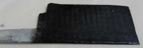 The sacrificial zinc electrode.
It turned black, and black flakes fell off of it.
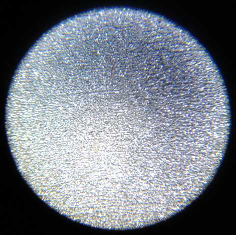
Microscope 5. The uniform plating on the main surface an electrode
after 15? minutes.
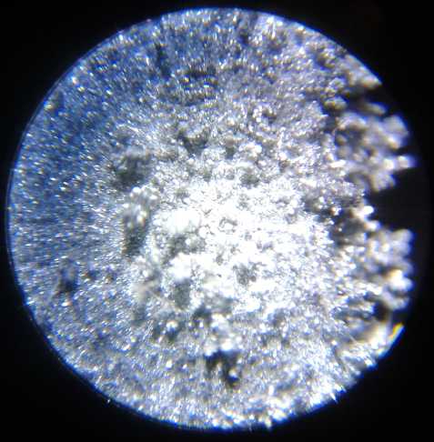
6. The fuzzy dendrite plating near and at the bottom edge. Dendrites
growing up
and those growing down over the edge couldn't all be brought
into focus at once.
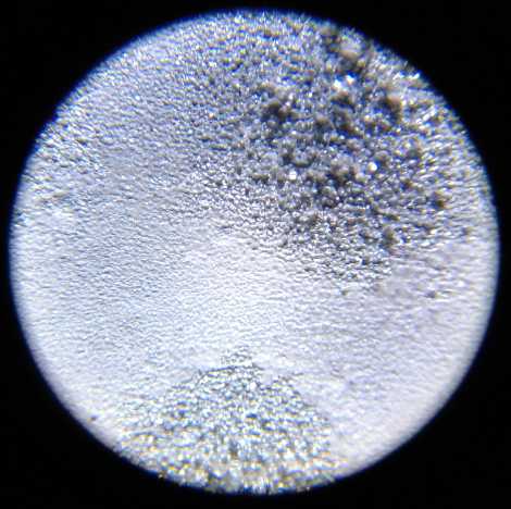
7. Plating where the mesh was and in the holes in between.
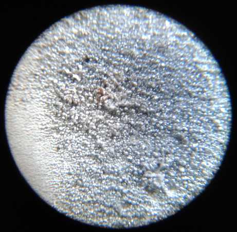
8. Fuzziness squashed down some in press.
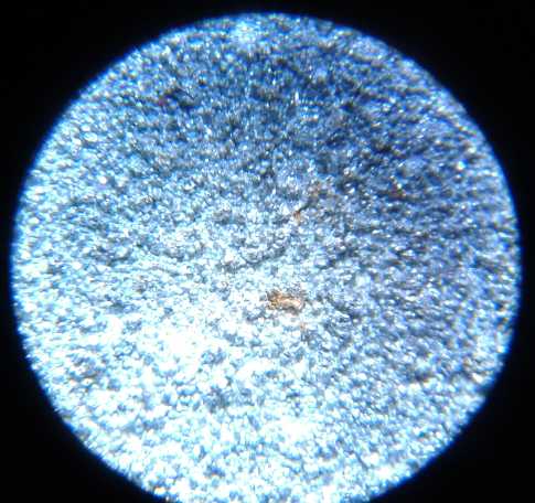
9. Fuzzy bottom edge squashed. (Is this the right slide?)
The electrode picked up bits of rust (or
paint) from the steel
blocks I squished it between - oops. But rust
should just sit
or else turn into metallic iron - it has a lower
voltage than zinc.
These images were all at 40x magnification. The relative
coarseness shows that zinc structures build and dissolve
electrochemically at "micro" scales - meaning sub-millimeter - but
nothing like a "nano" scale that would be hard or impossible to see in
the microscope even at 800x. Those ultra-fine zinc powders I bought in
years past were much finer than what I was now getting by
electroplating processes.
I decided to put just one battery electrode back in with two sheets of
grille between it and the other. Current started at 2.54 amps. Perhaps
5 amps for two wasn't a short circuit after all? Maybe it just was that
high doing the plating? I turned it around to do the other side.
Current rose to 3 amps... of course! as it plated, the electrode gained
surface area, so the current went up. Jumping up to 5 amps and hissing
as it was still doing, however, was surely dendrites shorting the
electrodes.
Then again, it started becoming quite plain that much of
the plating was happening right at the edges. They were very fuzzy and
it was obvious the fuzz was getting fat enough to short to the other
electrode. It would seem some sort of strip around the edge was needed.
The zinc at the edges couldn't grow larger than the slot it was in, and
it would limit electrolyte circulation in the edge areas. Perhaps the
electrodes should also be farther apart to slow it all down? Would that
make it more even? Perhaps a box, where all the electrodes lid down
into slots along both edges, each spaced at a distance so as not to
touch each other. This seemed to be moving from the area of experiments
into production issues. I suppose it already was when I decided to try
another liquid for electroplating even tho the first one worked.
Enough for that one! I could scrape off the edges, and it
had some plating across both faces. It was only about 1/2 hour's worth,
but I pulled it out and put the other one back in, with the previously
back face toward the other 'trode. 2 amps rose to 3.5... then limited
at 5.0 again until disturbed.
The alternative to taming the edges was if the entire
electrode could be so fuzzy. Then I would press it to a uniform
thickness and chop the edges to a set size. Worth considering!
In the meantime, even if not plated the sheet metal
zinctrodes worked quite well, and now they had some sort of plating. On
to the next and perhaps most vital experiment.
Egg Albumen Coating
After all these preliminaries I was back to the idea from
last month. I noticed that the ester coating seemed to deteriorate,
probably through electrolytic action, and so did the whole electrode
surface, as evidenced by the break of the first one at the water line.
Yet no dendrites had formed. Did the ester leave the osmium embedded in
the zinc surface and that somehow prevented dendrites?
But something I had thought about many times was that egg
shells, and the outer and inner membranes, allow oxygen to enter the
egg, carbon dioxide to exit, and yet prevent entry of bacteria and
escape of the egg's liquid. Here again we might gain an ion selective
membrane that would keep the zinc out of contact with the electrolyte
and so prevent it from dissolving into it. What I didn't see was a way
to harvest these layers from an egg and use them inside a battery.
The one layer that is accessible is the eggwhite, the
albumen. Perhaps, if the alkali didn't dissolve it, egg albumen once
dried could form a membrane to keep the zinc out of the electrolyte and
yet allow the ions in to react? It sounded like it might work.
Or perhaps the albumen in combination with the osmium doping would
prevent deterioration as well as dendrites? Mañana!
(12th) I got the powdered egg albumen out of the fridge. I
went to get some distilled water to mix it in. Was that what I should
use? Then I thought that if I used an actual egg, it was already liquid
without adding anything.
![[eggy]](EggOnFase.jpg) What luck - I
had eggs! I cracked one into a bowl. The
yolk broke, but I managed to dig out a couple of teaspoons from the
other side of the bowl, and put them on a dessert plate. Then I put the
electrode on the plate in the egg white, and used a small paintbrush to
coat the top and edges. I got out a small vise and turned it sideways
to hold the electrode level by its terminal tab. There was some left
and I got the other electrode and coated it too. (So much for doing the
osmium doping first on one of them! Not very methodical, am I?) Should
I cook it, or just let it air dry? I decided on the latter, again for
both. It seemed to me cooking it would wreck it.
What luck - I
had eggs! I cracked one into a bowl. The
yolk broke, but I managed to dig out a couple of teaspoons from the
other side of the bowl, and put them on a dessert plate. Then I put the
electrode on the plate in the egg white, and used a small paintbrush to
coat the top and edges. I got out a small vise and turned it sideways
to hold the electrode level by its terminal tab. There was some left
and I got the other electrode and coated it too. (So much for doing the
osmium doping first on one of them! Not very methodical, am I?) Should
I cook it, or just let it air dry? I decided on the latter, again for
both. It seemed to me cooking it would wreck it.
The rest of the egg I put a bit of cheese on and poached
in the microwave, and had on a toasted bagel with chard and green onion
from the garden, and (store) tomato. Nice!
There they were, two zinc electrodes, coated in drying
eggwhite. Could that be all that was needed, after 11-1/2 years of
trying to figure something out? After over 2 centuries of battery
making and dozens if not hundreds of patents by as many researchers for
how to sort-of solve the zinc dendrite problem? It remained to be seen.
It occurred to me that if the electrode already had an
insulating layer of albumen, there was - in theory - no need for a
separator sheet between electrodes. That might be leaving a lot to
chance, but perhaps I would use a thinner separator sheet than I would
otherwise have dared to use - some thin white polypropylene non-woven
cloth (thin "landscaping fabric".)
When I looked at the electrode surface under the
microscope, the egg layer which had seemed so sticky when wet looked to
be vanishingly thin except where there was some fuzzy zinc holding a
glob, or where there had been a bubble, which there had been several
of. It might be a good, thin membrane, or it might be that several
coats are required for good isolation of the zinc. (I'd better buy some
more eggs!)
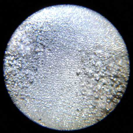 10. Virtually transparent egg Layer
Assembly and Testing
I made up a batch of electrolyte I'll call the "20-20"
mix. It was 100 cc of distilled water to which I added 20 cc of methyl
hydrate and 20 grams of potassium hydroxide flakes. The methyl
hydroxide, contrary to my original expectations, doesn't work as
electrolyte. It doesn't carry current itself, seems to cause rather
severe self discharge, and it even seems to inhibit the potassium
hydroxide from conducting current.
But the purpose here was to condition the eggwhite surface.
In the evening by which time I thought the eggwhite must
be well dried, I put one of the electrodes into the same little cell
with the same little pieces of nickel hydroxide electrode from the dry
cell. I folded a piece of the polypropylene cloth around it, but to
protect the eggwhite. I inserted the same grille as before between the
electrodes.
It started about 1.63 volts and started dropping bit by bit. I
conceived that perhaps the egg layer needed some charging and I hooked
up a 1.9 volt charge. It started at 50 mA but went down quickly to 20
mA or so, and after a bit it was below 10.
I shorted the current meter across the cell. 150 mA,
dropping to 90 in 10 seconds. Well, let's see what a little charging
would do. Of course, it wasn't charging in any hurry. I left it off,
and in the morning (13th) it was sitting a little over 1.2 volts.
I drained the liquid. It was even more of a purple color
than the zinc chloride, and nothing like the yellowish sodium zincate.
I'm confused. I refilled the cell with distilled water, and did that 3
times to dilute out whatever might be in it. Then I refilled it with
the 20% potassium hydroxide (20 g KOH in 100 cc H2O) electrolyte.
After a bit of charging, still at very low currents, it
seemed it would steadily put out 200 mA. It recovered voltage quite
slowly. The electrode was 33 x 55 mm, so 18.15 sq.cm, so that was just
11 mA/Sq.cm. At that rate it was going to take a lot of electrode
surface to get good amps!
Then I remembered the "+" side had acted up before and I
wiggled the "+" terminal with pliers. Charging current went up and the
short circuit drive became 290 mA. I was going to have to do something
about that side before coming to too many conclusions. And I was going
to have to look a long way back through TE News issues to find a good
positrode formula!
Antimony Sulfide or Zirconium Silicate?
After a couple of hours, the short circuit current hadn't
gone up much, but it would drive a 15 ohm load at 150 mA/1.5 V.
Definitely the zinc had started out fully charged and it was the nickel
hydroxide side that had to charge. So it occurred to me that the zinc
side must be bubbling hydrogen, and that hydrogen could surely get
through the eggwhite layer. That meant the zinc would be turning to
zinc hydride. Ugh!
If the idea of isolating the zinc from the liquid was
working, it didn't prevent all problems. I had once raised the hydrogen
overvoltage of manganese to the point where it would hold a charge.
With zinc, even in flooded cells it would probably be be advantageous
to raise the overvoltage. Was there a way to incorporate a trace
component into a plated plate of zinc instead of a powder electrode
like the manganese ones were? One can perhaps plate a metal, not a
compound. Perhaps I could plate zirconium? Maybe I could just paint
powdered zirconium silicate on/into the fuzzy plated electrode surface
before the egg? Mixed into the egg?
(Meanwhile, the zinc chloride I had made with zinc and
hydrochloric acid and which was still quite acidic last checked,
appeared to be growing a white mold on the surface. In less than one
day? In a beaker with a rubber stopper on it? Egads! I spooned it off,
whatever it was, and it didn't reappear.)
I hooked up a 60 ohm load... and forgot about it. Some
hours later, the cell was very discharged.
14th
I reconnected the charge and it started charging with
quite high current, almost 1/2 an amp and over 1/4 amp for a while. The
voltage slowly came up from .3 volts to 1.9. By then the current
dropped to 30 mA. I stopped charging and shorted the cell - over .3 A
for 10 seconds.
Soon there was some weirdness. I took the cell apart and
found dendrites - nearly all right at the fuzzy bottom of the
electrode. They had grown through the PP cloth, and one in one corner
had grown across the separator grille
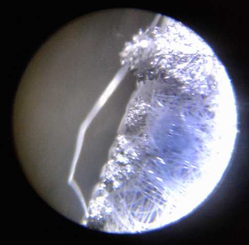 Microscope 11. dendrites at the bottom
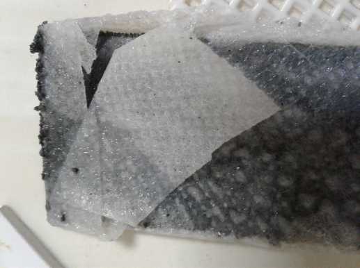
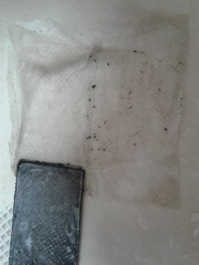
Separator cloth with dendrites
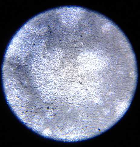
Microscope 12: Patchy surface
The surface of the zinc sheet was patchy. This seemed to
follow the pattern of the PP cloth and of the separator grille. Was the
cloth absorbing the egg and leaving the zinc bare? protecting the egg,
and the zinc was bare where there was no cloth? Should I try painting
the cloth with the eggwhite?
I wasn't ready to give up the theme yet. Noting how
vanishingly thin the eggwhite seemed in places, I suspected it would
take more than one coat to fully cover the zinc. It was certainly easy
to imagine the eggwhite shrinking back as it dried, and leaving
some or even all of those protruding points exposed. Maybe even several
coats would be necessary. A good, thick layer. Then too, chickens
weren't the only eggs. Most bird eggs are pretty similar in color and
taste. An exception is duck eggs.
Duck Eggs
Some friends had mentioned they would have duck eggs for
sale. They have darker, richer yolks that some like better and others
don't. At first I thought, nah!... but on looking them up, it seems
duck eggs are more oily and more waterproof than most bird eggs. Might
some difference apply to their whites too? So I bought a half dozen.
Electroplating Rack
I also gave some thought to electroplating the zinc
electrodes. They had once again plated mainly around the edges and
especially at the bottom where they sat against the glass. How might I
make them more uniform? The first thought was to make something so the
sheets had slots around the sides and bottom, limiting the extent to
which the edges could grow. If I was to do that, I would probably want
to make something that would do several electrodes at once, of my
intended production size. The second thought was that the sacrificial
electrodes could be smaller, and not extend out to the edges of the
sheets being plated. Then the currents would go more to the centers. So
the plastic cube would have slots, and other slots for the sacrificial
electrodes between each of the electrodes being plated as well as on
the outer two faces. I decided to make one that would fit in a
particular jar - Adams Peanut Butter 1L. They have the widest lid of
any glass jar I've seen. Hoping I wasn't wasting my time, here would be
the first little piece of equipment to make production go better and
faster.
![[ajar]](ZnElectroplatingTank.jpg) I
made the rack the next day (15th) from some scraps of
plastic. It just fit in the jar - after I sanded the corners off. And I
cut some bits off the top so the lid could go on the jar with the rack
still in it. My intent was that it should hold up to 3 battery
electrodes between 5 smaller sacrificial electrodes. But having got 4
slots, it seemed easier just to put in one battery electrode with equal
size sacrificial ones on each side of it. Especially just to try it out.
I
made the rack the next day (15th) from some scraps of
plastic. It just fit in the jar - after I sanded the corners off. And I
cut some bits off the top so the lid could go on the jar with the rack
still in it. My intent was that it should hold up to 3 battery
electrodes between 5 smaller sacrificial electrodes. But having got 4
slots, it seemed easier just to put in one battery electrode with equal
size sacrificial ones on each side of it. Especially just to try it out.
Some zinc chloride had settled on the bottom of the
beaker, so obviously it was too concentrated. But 100 cc became pretty
diluted, I'm sure, in a 1 liter jar filled almost full with distilled
water. Nevertheless, when I connected power, it started out at 3-3/4
amps and went up from there. Well, if it's to have that many amp-hours
of zinc plated onto it, it needs that many amps for an hour. Soon it
started bubbling. Let's see...
Positive: Zn + 2 Cl- => ZnCl(aq) + 2 e-
Negative: ZnCl(aq) + 2 e- => Zn + 2 Cl-
What part of that is bubbles? It must be hydrogen. Lets
see... Zn in pH 14 alkali is -1.28 volts. Zn in neutral salt is ~
-1.0V. I turned the power supply down from 1.5 volts to 1.0. The
current dropped to 2-3/4 amps. Hmm, the sacrificial zinc could be
bubbling oxygen and making zinc hydroxide, which would be balanced by
the negative side bubbling hydrogen. Of course. And then it would all
turn more and more alkaline with hydroxide as water was converted to H2
+ Zn++:(OH-)2. Probably to around pH 12. So what was the chloride for,
again? Well, that would be in there too! Maybe it would plate with a
more favorable porosity?
![[foto]](SumPlating.jpg) I pulled two
of the three electrodes out. The sacrificial
one had some black on it. The one being plated seemed to be getting a
nice uniform coat except around the edges that were in the slots, and
various places that obviously weren't clean. Apparently the roll of
zinc had got wet and had a discoloration all along one side, and I
hadn't etched these electrodes, only buffed them with scotchbrite. It
obviously wasn't a good cleaning.
I pulled two
of the three electrodes out. The sacrificial
one had some black on it. The one being plated seemed to be getting a
nice uniform coat except around the edges that were in the slots, and
various places that obviously weren't clean. Apparently the roll of
zinc had got wet and had a discoloration all along one side, and I
hadn't etched these electrodes, only buffed them with scotchbrite. It
obviously wasn't a good cleaning.
Now I tried scouring with baking soda but nothing would
clean off that line. I dipped it in the old, weak ferric chloride. Then
it was black. But if the black was zinc chloride, and I was using zinc
chloride electrolyte for the plating, did I need to clean it off? I put
it in the tank and hooked it up. I turned the voltage up to 1.1 and it
was about 2-1/2 amps.
After a few minutes it didn't really look very good, so I dipped
it again and then cleaned it with varsol. It still didn't look
very clean. But I put it in the plating solution again. The plating
didn't look perfect, but it was more even. The pH was 5. All 3
electrodes had lots of very tiny bubbles coming off them. I turned it
down to .9 volts, and then .8, but it seemed to be working much the
same. I left it for maybe a couple of hours(?) and worked on somthing
else.
When I came back it seemed to have a nice, even plating -
not a bunch of dendrites. The side edges in the slots had almost
nothing, but it seemed the bottom edge hadn't gone into the slot and it
was coated - but this time pretty evenly compared with the rest - even
a bit lighter. The the original sheet was .3 mm thick. The plated
electrode was 1.2 mm. Before coating the piece would have been about 18
grams. After coating it was 25.55 grams (wet) so say 25 grams. That
would be a theoretical 7 g * .820 AH/g = 5.74 amp-hours added by the
plating - in practice hopefully a couple of amp-hours on each side. And
it could easily be made thicker by putting it in longer. It was an
excellent result.
Instead of making this one thicker, I dipped the first one
with the splotchy plating in the ferric chloride, cleaned it off in
varsol (still didn't look clean), and put it in to plate. Starting
current was just under 2 amps, which rose to a little over 2 amps,
still at .8 volts.
The rack is great and I'll use it for now. But having used
it now I have a "next version" in mind.
* There seems to be no need to have the sacrificial electrodes smaller
in area - the coating is pretty uniform.
* So then, the 3/8 to 1/2" spacing of the slots can be reduced to 1/4"
or so - no smaller electrodes between the ones being plated, just an
evenly spaced stack with every second one being sacrificial.
* Second, the edge slots will be narrower so the plating comes closer
to the
edges of the sheet. (Caution: the other roll of zinc is 1 mm narrower
than the first one, so don't make it too close to the
edge! How variable is the width of the rolls?)
* Third, the bottom slots will have tapered entries so the sheets don't
get stuck just before they enter.
* Tapered entries to the top of the edge slots would be better, too.
It still looked pretty splotchy, so I made two new
electrodes, dipped and cleaned them as best I could, and put one in. I
left it on a couple of hours at 2 amps, .8 volts. The coating was
thick, but soft and flaky. It rubbed off easily. It was a bit like
fluffy trees growing up from the surface, and only one height could be
brought into focus at a time under the microscope. One side was pretty
uniform, but the other had some missing patches.
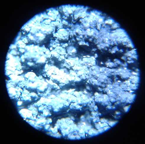 Microscope slide 13. Heavy zinc electroplating
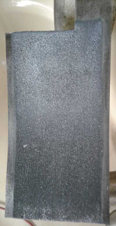
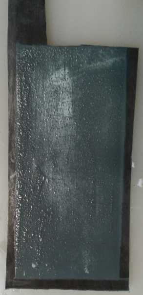
3 faces of the 2 plated electrodes
If the fragile plating could be coerced
to stay where it
was, it certainly had a lot of surface area for a relatively small
volume. Obviously the way to get it to stay, if it would work, would be
a thick coating of eggwhite encasing it all.
The thickness went from .3 mm to 2.3 mm, yet the weight
only (almost exactly) doubled. That meant that .3 of 2.0 was zinc, 15%;
the other 85% was air spaces. That certainly must mean lots of surface
area for electrochemical reactions.
The weight increase asked a question: how did it go from
17 grams to 34, adding 17 g * .820 AH/g = 14 amp-hours with around 2
hours plating at 2 amps - 4 amp-hours? That doesn't make sense to me.
![[foto]](SacrifishalTrodes.jpg) The sacrificial electrodes were now almost
"aluminum foil"
thickness and had gone from 17 or 18 grams to 9 and 11, losing about 17
grams of zinc. (Quite even un-plating - no holes in them yet! Oops,
there are a few pinholes in one patch on one. That whole patch will
surely
be gone next time!) The other few grams for the first one must have
come from the zinc chloride already in solution. (The excess becoming
exhausted probably explains why the currents went down from 4 amps to
2.)
The sacrificial electrodes were now almost
"aluminum foil"
thickness and had gone from 17 or 18 grams to 9 and 11, losing about 17
grams of zinc. (Quite even un-plating - no holes in them yet! Oops,
there are a few pinholes in one patch on one. That whole patch will
surely
be gone next time!) The other few grams for the first one must have
come from the zinc chloride already in solution. (The excess becoming
exhausted probably explains why the currents went down from 4 amps to
2.)
Examination of the previous electrode showed that it was
really much like the latest except thinner and stiffer. The start of
the dendrite growth with air spaces between was there. It would make a
good electrode.
I got out a duck egg. It
looked suspiciously like a
chicken egg, but the shell was a lot harder and thicker. The membrane
inside it was thick and rubbery. I poured the 'white' into a small
ointment jar. I spooned a little zirconium silicate (AKA zircon) into a
small plastic cup and added some eggwhite. I put the lid on the jar and
put it in the freezer. I mixed the eggwhite and the zircon in the cup
and painted it onto both the small electrodes (which already had been
painted with chicken egg), including the one that had shorted with
dendrites. I considered doing one of the big ones just plated, but
decided to stick to practicing on the small ones.
A Positive Electrode
The performance of the cells, and especially the last one,
seemed to be limited by the pieces of NiMH dry cell I was using for the
positive electrode. What with take-aparts and reassemblies, the
conductive nickel 'tape' had come loose and off and it just got worse.
I got a piece of nickel foam out of the cupboard. With pH
14 alkali, at least I knew nickel was one metal that would remain
intact in the positive electrode, so here was a good current collector.
IIRC it was 97% air. What should I fill that 97% with? I picked the
first 'positrode' mix from TE News #73, calculated to make a good
nickel-manganate electrode compound. But I would use the nickel foam
instead of carbon foam. When I actually mixed it I used less carbon
black (5 g vs 20 g) because it was so light and fluffy that a little
weight was a lot of volume. It was the only thing that filled the 50cc
beaker to overflowing, with just 5 grams. Also a little less samarium
oxide (5 g vs 7 g) because it just seemed like so much of what is just
a trace ingredient, compared to the rest.
Monel Powder - 16 g
Ni(OH)2 - 17 g
KMnO4 - 40 g
Graphite Powder - 5 g
Sm2O3 - 5 g
total 83 grams instead of 100. The proportion of nickel to manganese
for forming nickel manganates was the main consideration.
I then tried to make a porous 3D printed plastic shell for
the electrode, but without success. More on that is below.
Finally I decided to just use another piece of the NiMH
dry cell nickel hydroxide electrode for the time being.
I put it together with parchment paper wrapped around the
nickel parts and no grille between electrodes. The short circuit
current was disappointing, around 200 mA, but it kept up that level.
Probably it can be improved. But better low current and a battery that
lasts than high current and a short cycle life. (I looked up last month
and I see it was only after some cycles they started getting the higher
currents I was remembering.)
I charged it some hours, then turned it off. Some hours
later (20th) it read 1.593 volts. But it still put out similar current
when shorted, so it wasn't much discharged. Since they charged to over
1.7 volts before, something seemed to have changed. I suspect that with
the zinc no longer in direct contact with the electrolyte, the pH level
at the zinc is reduced. The reaction voltage of zinc drops with the pH.
A 1.6 volt level resting might suggest pH of 8 to 11(?).
I tried a discharge test later with a 60 ohm load. The
voltage dropped over the seconds instead of the minutes, and within 5
minutes it was down to 1/2 a volt. Over a couple of minutes it
recovered to 1.6 volts and more gradually to 1.65. That doesn't say
much for the current capacity! Next question: was the problem in the
nickel electrode chunks, the parchment paper or the duck eggwhite?
Removing the paper and putting the grille back in made no notable
difference. Neither did replacing the coated zinc electrode with a
plain piece of zinc. (Of course, it was now just a flat smooth
surface.) I put a piece of nickel foam beween the nickel hydroxide and
the cupro-nickel collector plate hoping for better conductivity. There
was no evident difference in the short circuit current, but the
charging current went up substantially and it took many minutes to get
up to 1.9 volts instead of many seconds. So the problem was probably
the nickel electrode.
Parchment Paper Separator
I note that the parchment paper seems to be a very good
separator paper. It still seemed good after a couple of uses and it
held the little bits coming off the nickel oxides electrode contained.
(Now... does it gradually deteriorate, or last "forever"? Looks like
the latter so far.) But with the porous plastic positrode shells to
hold the "trodes" apart I decided to use the also paper thin non-woven
PP cloth as being likely to conduct ions more freely.
3D Printed Positrode Shells
But whatever the mix, how was this positrode to be held
together? The nickel foam was only .5mm thick. The dry cell electrodes
had been together packed into the cell so long that they tended to hold
together by themselves even in the open. My experience with my own
powder electrodes has been that the compacted "briquettes" tend to
expand into whatever space
they can find once wetted in the cell. And yet, I didn't want them
packed tightly against the zinc electrodes. But all the extra metal in
pocket electrodes seemed so wasteful.
The "plastic pocket" electrode idea came back to me on the
night of the 18th. What had I been trying to achieve? porous plastic
sheets for pocket faces. What had I been missing all this time? All I
needed to do was thin out the extrusion with a one-time (per session)
manual command to the printer until the plastic was thin and porous
instead of "pretty solid": M92 E750 (or whatever), where M92 E1000 was
the "neutral point" for the amount of plastic filament to extrude and
E750 would only print 3/4 as much, which should leave tiny gaps in the
"weave". When I checked I had actually done that before so I was
revisiting old territory, but now I had a couple of different ideas.
![[picture]](TrodeShell1ABS.jpg) When I had the thought I
immediately went and turned on the laptop computer I use with the 3D
printer and started on a better design. Instead of making it so the
electrode "innards" are slipped in through a gap at the top as I had
done before, they would
be placed in the bottom half shell, and then the top half would be
glued on with
methylene chloride. That should make for a much tighter fit with no
leaks.
When I had the thought I
immediately went and turned on the laptop computer I use with the 3D
printer and started on a better design. Instead of making it so the
electrode "innards" are slipped in through a gap at the top as I had
done before, they would
be placed in the bottom half shell, and then the top half would be
glued on with
methylene chloride. That should make for a much tighter fit with no
leaks.
Another idea is to put some paper inside to line the
plastic. That way no little gaps in the plastic can leak material. And
between the paper and the plastic lining the active electrode, the
electrodes in the cell could actually touch each other - stack against
each other, in principle without risk of anything shorting.
But the shells wouldn't have the "porous" gaps that I was
hoping for. The second layer was fine, but the first layer gets smeared
against the glass printing bed. If it doesn't the part comes loose. The
smear effect ensured that there were few gaps in the first layer.
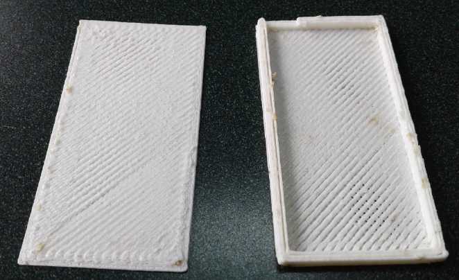 I made a
second, improved box. The first had
been two
halves. This one was one piece being a box with sides, and the other a
flat cover. The full height (electrode thickness) sides would contain
the electrode better during assembly.
I made a
second, improved box. The first had
been two
halves. This one was one piece being a box with sides, and the other a
flat cover. The full height (electrode thickness) sides would contain
the electrode better during assembly.
![[foto]](NotVeryPorusABS.jpg) But the box
was only porous as intended in one area. In the rest the plastic was
all merged.
But the box
was only porous as intended in one area. In the rest the plastic was
all merged.
Then I clicked on a command
to heat up the extruder while
the "skeinforge" was turning the 3D .STL file into .GCODE printer
commands. I've never made any interruption before during the skeinforge
"slicing"
process. Apparently it didn't like it. Nothing worked after that. The
temperatures and temperature setpoints just said 0/0, 0/0 .
When I tried
to tell it to move it said "Printer halted due to error. (Temperature
reset. Set temperature before issuing M999 to restart printer.)" I
didn't even know if it was the computer software or the printer. (Later
I found that string of text in the source code for the printer itself,
so it was the printer returning that message.) Anyway,
setting the temperature of the bed or the extruder did nothing. Perhaps
the temperature setting commands too were ignored because the printer
was "halted", so it couldn't fix itself. (Incomplete testing of the
printer firmware? It was an old 2011 version.) The
temperature setting return from the printer continued to say "0" along
with the other numbers. (And didn't they used to say "-273" initially
before they were set? Why now "0"?) I worked long into the night, and I
was unable to get anything going on the 19th, either. There was almost
nothing on line about the problem. What there was said to fix the
extruder thermistor. But the thermistor had been fine. It read 2.5
volts, which seemed reasonable.
I was now getting into the "Marlin" source code of the
firmware program inside the microcontroller of printer itself. No doubt
as a programmer I could eventually get to the bottom of this.
But it wasn't anything I wanted to get involved with. What frustration!
Regardless, by the 21st I had come up with a modified plan
for the shells: Make the
bottom layer, which can't seem to be made porous, into a grille, just
thin lines going across. That
would definitely have holes in it, albeit too big to stop particle
leakage. Above that (inside of that in the electrode 'box', is
optional. (It might take a coon's age to print that bottom layer. So
what?)
Option 1: Add two more layers, which would come out with crosshatch
pores if printed thinly, on top of the grille. Thickness would be 1.2
mm.
Option 2: The grille could be continued for a second layer, line going
crossways to the first - .8 mm
thickness, and a sheet of parchment paper could be layed down flat on
the inside. (3 or 4 layers, making the grille 1.2 or 1.6 mm thickness,
would make it stiffer.) A solid strip (no grille) around the edges
would prevent leakage at the edges of the paper. The parchment paper is
only .04 mm thick, so even several layers of it wouldn't add much
thickness. The plastic would be extruded at normal thickness.
The thickness is important. If the electrode is say 2 mm
thick, then 1.2 mm for each face, 2.4 mm, would mean there's more
plastic than electrode. OTOH a short circuit through a sheet of
parchment paper plus 1.2 mm of plastic grille will be pretty unlikely
in the absence of dendrites forming bridges.
I think of stiffness as being important to hold the
electrode powders compacted together. But if the cell was wholly filled
with alternating plastic encased oxide "+" and zinc "-" plates stacked
against each other, the stiffness of the plastic only has to hold until
and during cell assembly, and before it is wetted. That shouldn't take
much. (And it shouldn't take much electrolyte, either.)
Option 3: Get the "Anycubic I3 Mega" printer software working and see
what could be done with that printer. It prints finer beads than the
old RepRap.
I set it aside for a while.
Ethaline Deep Eutectic Solvent (DES)
I found the following text reading a write-up on zinc
oxides that has been on my drive for some time.
(ZnO_Zn(OH)2-info.txt - source uncertain)
"The solubilities of zinc oxide
and zinc hydroxide are at a minimum at pH 9.3. At this pH, the
solubility of zinc hydroxide is 0.0822 mg/L for the amorphous form and
0.0041 mg/L for the <greek-e>-Zn(OH)<INF>2 form. Zinc
oxide and hydroxide are insoluble in organic solvents, including
alcohols and acetone (Refs. 3, 5-9)."
At first glance the mention of solubilities at lower alkaline pH
would seem to be in conflict with Pourbaix pH diagrams showingZnO and
Zn(OH)2 to
be insoluble from about pH 7 to 13. However, 82 and 4.1 micrograms per
liter could be said to be pretty much "insoluble". OTOH, my unprotected
zinc electrodes seemed to form dendrites at any pH, which I hadn't
expected.
But the really interesting part is that it says it's not
soluble in organic solvents... perhaps like ethaline DES? Perhaps all
one needs to do to prevent zinc electrodes from dissolving is to use
that electrolyte? (Wouldn't someone have found that out by now? But I
didn't see much of relevance on the web. And how soluble is
"insoluble"? Do they really mean zero PPM?)
Until now I had thought that the key advantage to ethaline
was
that it had a wider voltage range than water. A chart shows ethaline as
being stable from about -1 volt to +1.25 volts, but gives no indication
of change with pH. (Water is only -.8 to +.45 at pH 14.)
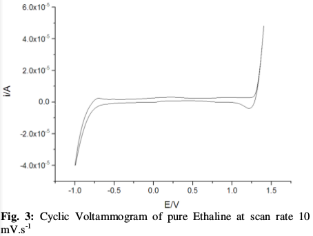
But if zinc was really insoluble in ethaline it would
solve the dendrite problem. That was a different tack than I had been
taking, but it seemed well worth exploring. The eggwhite might work
fine, but it wouldn't need much of a gap in the coating to annul the
effect, and it wouldn't be exactly a hard thing to scratch a slot in
accidentally during assembly. This should be more reliable.
On the 21st I decided to try it. I took the cell apart and
rinsed everything off, then let it dry. I got out the ethaline, and
found there was only 15 cc of it. I added 3 grams of potassium
hydroxide flakes - 20%, as before. For a while I wasn't sure it would
dissolve. If not, what would I do? But very gradually the flakes
started turning to mush and I thought after an hour there was less
substance on the bottom. (Certainly no worries about the reaction
generating too much heat like it does in water!) In several hours the
lumps were all gone but it still hadn't clarified. I used it anyway. It
poured like molasses.
In the meantime, I wanted a new, electroplated, non-coated
zinc electrode in the test cell size, so I set about making one of
those. Before electroplating it would have been around 4.4 grams. After
it weighed 6.1, so 1.7 g of high surface area plating, a theoretical
1.4 amp-hours - .7 AH on each face.
By evening I finally put the cell together. Currents were
very disappointing - 5 mA charge current. 20 mA initial short circuit
and dropping by the second from there. It might work fine and grow no
dendrites, but I wasn't sure it was much good for anything with such
low current capacity. And the only thing between the electrodes is two
thicknesses of parchment paper. Apparently the high viscosity severely
limited ion flow - but that has long been noted by others. Wiggling the
positive lead seemed to make little or no difference, and it didn't
feel loose. A while and some charging later it would start at 35 mA
shorted. It was still a long way from even 150 mA, let alone an amp or
two. Was there any way to improve it? Could some thin solvent be added
and mixed in to reduce the viscosity?
Longer charging disclosed the certainty that it was self
discharging, and pretty rapidly. Not good! It would discharge down to
around 1.2 volts and then stay there. Shorting it said there was still
some energy in it. What was happening? The voltages might be a clue:
NiOOH +49V; Zn -1.24V. Might it be that it was discharging the nickel
electrode, but not the zinc? Ethaline is supposed to handle up to
+1.25V, but maybe there was some chemical incompatibility? What would
happen if I tried an MnO2 trode with its lower +.15V reaction voltage?
But when I went to pour the electrolyte out of the cell,
nothing came out. Was there not enough to pour? Or had it turned to a
jell? Turning it sideways and shining a flashlight in seemed to
indicate the latter. Although the cell was no longer full**, a little
fluid was visible and it didn't start oozing toward the lower side. The
cell had had a reasonably tight fitting lid on it. The ethaline with
KOH still in the beaker, with an even less perfect cap (the rubber
stopper has a gap at the beak) was still viscous liquid.
Here was an interesting and unexpected overnight
development. The electrolyte itself seemed to be changing as the cell
was being charged. What would happen if I just kept charging it? or
even if I just let it sit some hours or days? I decided to let it sit a
few hours before trying to charge it again. But nothing changed, and
when I opened the cell on the 25th, I found my perception was wrong:
the DES was still liquid, however viscous.
I noticed something odd about the ethaline still in the
beaker. It had still not clarified since adding the KOH. Of more note,
there was a clarified layer 2-3mm deep on top (yellowish), then 7-8mm
of unclear liquid (colorless) under it. As if the KOH had dispersed as
an emulsion but not dissolved, or not entirely dissolved, in the lower
part, but had dissolved or was being expelled from the upper part. This
was supposed to be one liquid: why would it separate into two layers?
If it did have two components, was only one of them the DES for the
cell? Could the presence of the other be what was causing problems?
The jelled(?) ethaline in the cell couldn't be modified.
It surely contained both components. I could probably separate the
clearly defined layers in the beaker, but there wasn't enough in the
beaker to do much with. (Maybe I could fill one small cell with the
cloudy but colorless part.) If I wanted to try more things, I would
have to make more ethaline and new cells.
** Being so viscous, I suspect the ethaline only gradually seeped into
small cracks and wetted more electrode surfaces in the cell, so the
level dropped some, gradually, after I had filled it and closed the
cover.
![[imidj]](ThinCase.jpg) Also on the
25th I made a cell case for "full size" electrodes but only thick
enough for two (or maybe three with two thin zincs around a single
oxide one). Basically it's for testing "full size" 'trodes. But I
didn't get as far as to use it. I look forward to
getting amps instead of 100 milliamps.
Also on the
25th I made a cell case for "full size" electrodes but only thick
enough for two (or maybe three with two thin zincs around a single
oxide one). Basically it's for testing "full size" 'trodes. But I
didn't get as far as to use it. I look forward to
getting amps instead of 100 milliamps.
Ethaline Electrode Jell for Zinc?
On the 23rd a new idea occurred to me: If the ethaline
would jell or solidify, perhaps it could be painted on the zinc similar
to the eggwhite, and 'ordinary' water with KOH could be the electrolyte
for the positive. If the ethaline didn't touch the positive electrode,
it couldn't cause it to discharge. And maybe the current capacity would
go up too. And jelled electrodes last 'forever'. And ethaline has a
higher hydrogen reaction voltage than water, presumably reducing
gassing versus eggwhite & water.
I had already started thinking, "What might one synthesize
that would do the same job as eggwhite, but probably better?"
... maybe ethaline was it? It seemed worth trying.
I painted the best looking of my electroplated "full size"
zinc electrodes with the ethaline + KOH still in the test tube (simply
mixing the layers), both sides and up the terminal tab a ways. (I had
been about to paint it with duck eggwhite.) I left it to dry a while
before a second coat, but I don't suppose it was very dry. In the
second coat I added zircon powder as an extra buffer against hydrogen
generation. But after a couple of days I had the impression that the
DES had simply evaporated rather than dried. After all, it is a
solvent, of sorts.
Having already mixed some duck eggwhite and zircon, I was
painting the other large plated Zn electrode with that for possible
comparison. But only coating one side at a time and letting it dry,
then flipping it and doing the other side. After two coats and as many
days, it was starting to look coated. I went for 3 coats and was still
painting on the 25th. On the 24th I made a skinny battery box for just
2 or 3 of the large size electrodes - one that wouldn't take a lot of
electrolyte to fill.
But when I opened the cell I found I was mistaken and that
it hadn't actually jelled. Well, then... could it be induced to jell
somehow? How about agar? I got some and painted it onto the small DES
soaked electrode. It seemed to go on well, but the fuzzy zinc plating
seemed to come off into the goo. Not to change the topic here, It
seemed to make a nice thick layer, dark colored with the zinc "powder"
bits in it. But did I need to heat it as one normally does to jell
agar? If I did, would it jell in DES anyway? And what would happen to
the DES? Would the zinc bits poke through the jell and start making
dendrites? Would the whole thing work anyway?
It was like I was painting zinc powder back onto the
electrode. I think my zinc electroplating is too fuzzy - the
stems of the leafy 'trees' of zinc are too thin and so the tops break
off easily. There must be some way to adjust the plating process. Maybe
have the plus and minus electrodes somewhat farther apart? Adjust the
voltage?
Agar Alone - Zinc Electroplating Adjustments?
Okay, what about going back to something I tried years ago
but didn't try with zinc... just coat the whole electrode with agar?
(instead
of "egger"... and no DES.) Could it really be that simple? Again, it
seemed like something worth trying.
So I went and read up on agar. "Ideal pH 5.4 to 5.7".
Although that was under the "horticulture" section, a first question
then was: what happens to the agar in KOH solution? If it doesn't like
such strong alkali, it may once again be necessary to try lower pH
electrolytes. Agar also has temperature state-change hysteresis: It
melts
at 85°C and freezes (jells) at 32 to 40°. That means once it's
solid
the battery could get up to 40 or 50 without the agar liquifying.
I was making (yet another) new electrode to try with no
coating except agar. (I would have just used plain zinc sheet, but I
figured the agar would adhere better to a fuzzy surface.) There was
another thing I could try. I had been trying plating at .8 volts. I
went to go lower, but it turned out the power supply wouldn't go any
lower. What about higher then? I went back to my original 1.5 volts.
That should plate it fast, anyway.
I cut the zinc sheet a bit too thick and too tall. I
dipped it in hydrochloric acid for a moment. (wow that works fast!)
Then I trimmed it by hand and ended up at 29mm x 66mm - 19.14 sq.cm. It
would fit in the test cell easily even with a thick coating of jell.
I plated it for a while, not very thickly. It drew 1.1 to
2 amps, increasing as the sheet plated and gained surface area.
I put some distilled water in a petri dish and heated it
to boiling in the microwave. I sprinkled in some agar powder and
stirred it with a fork. In the fridge it turned to a fairly soft jell.
(Later it was substantially harder.) I heated it again and part of it
melted. I dipped in the electrode. Of course it solidified quickly as
it cooled, and it was thick enough to just need one coat. (After days I
was still waiting to paint the next coat of egg on the other electrode!)
...I forgot to add the zircon. Oh well.
First test: simply dip it in KOH electrolyte and see if
the agar dissolved. After a couple of hours it looked fine and felt no
different! It was
actually hard to see much under the microscope as the jell was almost
transparent.
Next: put together a cell with it. More chunks of the NiMH
nickel oxides electrode again. It started off at 1.45 volts but
dropping. Soon it was charging at 1.9 V, 30 mA, and would deliver
hundreds of milliamps, increasing as it charged. The voltage didn't
dive off a cliff as with the DES. After a while I saw "2.2 A" flash by
just as I shorted it - over 100 mA/sq.cm. (Later I never saw more than
1.5 A.) After some charging, it would continue to put out 290 or 300 mA
when shorted.
So... a good nickel-zinc cell. The agar conducted ions,
apparently, at usable but not high current. The next question was how
it would
hold out inside the cell with charging and discharging. Unless it
disintegrated, it looked like this was a simple, high energy, long life
battery. If there was a gap and dendrites formed, yet most of the
coating was good, it should be just a matter of improving the coating
technique - perhaps painting it on as I did in 2010.
The rest would just be working out manufacturing with
established or new techniques, optimum formulas and proportions, and
any further improvements that might be found.
Electrodes jelled with agar,
January 2010.
...painted quite thickly on quite thick electrodes.
If the negative had been zinc, perhaps I'd have
got much farther years sooner, with fewer detours
along the way? But that Mn negative wouldn't have
held a charge in 2010 as I hadn't found the trace
additives Mn requires at that time.
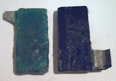 I dug back to
see when I had first thought of using agar to jell electrodes, thinking
2012 or 2014. It was worse than that: I first mentioned the idea of
using agar in
electrodes in TE News #8, covering September 2008. At that time I
didn't understand some key points of what I was doing and I didn't
realize how to use it. It would seem I used it, but in electrodes and
cells that weren't successful for one reason or another. Have I been
sitting on a key factor for 11 years? The new working agar coated zinc
plate electrode seemed to say so.
I dug back to
see when I had first thought of using agar to jell electrodes, thinking
2012 or 2014. It was worse than that: I first mentioned the idea of
using agar in
electrodes in TE News #8, covering September 2008. At that time I
didn't understand some key points of what I was doing and I didn't
realize how to use it. It would seem I used it, but in electrodes and
cells that weren't successful for one reason or another. Have I been
sitting on a key factor for 11 years? The new working agar coated zinc
plate electrode seemed to say so.
It's odd no one else has come up with this idea in a
couple of centuries, or even recently. It's hinted at on Wikipedia
(uses of agar: electrochemistry -- read between the lines). And this
picture was in TE News #24 and I guess it didn't fire anyone's
imagination... or was it? Egads, No! Somehow TE News #24 had been
replaced by a very incomplete draft that must have been done early in
the month. I looked on my computer and found
"TENews24-real.html", which looked like the finished version with a
file date of months later. Something funny must have happened way back
then. I'll upload the "-real" one when I upload this one. Perhaps I
meant to then and forgot. (I think that was probably about when I was
transferring the site from shaw.ca .)
Salted Jell
I wondered if maybe adding KOH to the agar would make it
more conduct current better. I put a gram into a shallow petri dish of
agar. The pH went from 6 to 12. (I was surprised it didn't jump to 14.)
It got thick but it didn't properly jell, even in the fridge. What did
that mean for its long-term prospects in KOH electrolyte?
![[trode]](SaltedAgarTrode.jpg) So what else? Next I made and plated another electrode
(with about 1g Zn plating). I tried a gram of potassium chloride salt
in a similar batch of agar. It jelled. I painted some onto the
electrode. Normally a zinc electrode wouldn't last in salt, as it
doesn't in 'standard' dry cells. I hoped the agar would change that
picture.
So what else? Next I made and plated another electrode
(with about 1g Zn plating). I tried a gram of potassium chloride salt
in a similar batch of agar. It jelled. I painted some onto the
electrode. Normally a zinc electrode wouldn't last in salt, as it
doesn't in 'standard' dry cells. I hoped the agar would change that
picture.
Next was a test: I would open the cell and inspect the
plain agar coated electrode. If its agar looked okay, I would exchange
it for the salty agar electrode. If it didn't, I would drain and rinse
out the potassium hydroxide and replace it with potassium chloride. Now
I feel like I'm going back to 2010. Except with zinc (known to work)
and salted agar. I sort of remember that my positive electrodes would
slowly self-discharge in KCl. Was it the graphite powder? voltage of
nickel oxide too high at a more neutral pH? Or was my assessment of
what was happening wrong or is my memory faulty? Well, let's check it
all out again. If nickel has trouble, manganese oxides in graphite or
conductive carbon black definitely work in neutral salt. Billions of
'standard' dry cells say so.
Well, maybe no need to go there... the agared electrode I
took out looked fine.
If there was any problem with agar in potassium hydroxide solution, it
would apparently take weeks to show. The jell seemed to cover it all
and it was still solid. There was no sign of any dendrites forming.
(Not that I had run it that long.)
So I just put the new electrode with the salted agar into
the cell. It seemed to perform almost identically to the other one.
That seemed disappointing - I was hoping for substantially higher
currents. Well, I just heated up some of the previous jell and mixed a
gram of KCl into it. Next time I would add the salt to the water, heat
it and then add the agar.
So it appeared I had a cell method - agared zinc - that
wouldn't soon form dendrites and and short out. But it was anything but
high current. One might conceivably make quite large batteries for bulk
solar storage this way, where they would charge slowly during the day
and put out a few amps for a long time overnight. But running electric
transport would be pretty much out of the question.
Getting Current - Osmium Doped Film
Again
On the 28th I looked back at June's newsletter, #133.
Currents had definitely been higher before the albumen and agar
coatings - and with the osmium film. What would happen if I
electroplated a zinc trode, painted it with the film, and then dipped
it in agar?
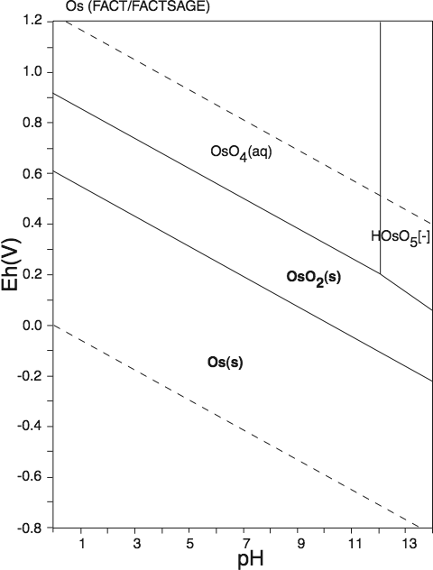 FWIW: Osmium Pourbaix Diagram.
Any osmium in contact with the zinc at
-1.x volts will stay in solid metallic form.
![[imidj]](UnevenZnPlating.jpg) So... another new electrode! It weighed 4.1 g before
plating. After it was 5.55. There were 'bald' patches - not clean
enough? I rubbed off the crumbly bits around the
edges and it was down to 5.3. Theoretically an amp-hour of plating -
half an amp-hour per side. I
only painted the osmium film on one side, since there was only one
other electrode in the test cell and I don't have much.
So... another new electrode! It weighed 4.1 g before
plating. After it was 5.55. There were 'bald' patches - not clean
enough? I rubbed off the crumbly bits around the
edges and it was down to 5.3. Theoretically an amp-hour of plating -
half an amp-hour per side. I
only painted the osmium film on one side, since there was only one
other electrode in the test cell and I don't have much.
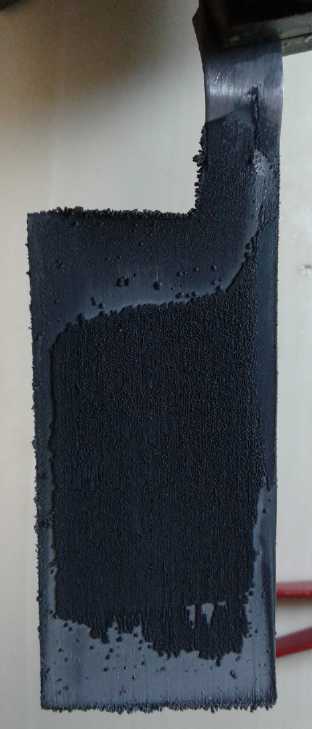
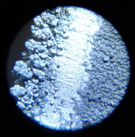 Electroplating at the edge:
Crumbly bits go around edge, a smoother line,
more uniform interior coating.
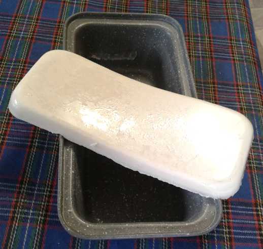 For the agar
dip I
sprinkled in maybe a couple of
teaspoons of samarium oxide. (Raises oxygen overvoltage. How absent
minded I am -- it's supposed to be zirconium silicate (zircon) to raise
hydrogen
overvoltage! I only realized the mistake late the next evening. I guess
I can toss that batch! Still, it's not a critical point unless the zinc
corrodes from hydrogen bubbles, and otherwise wouldn't have.) Then I
poured
in 250 cc of distilled water. Then I added 10.0 grams (~3 teaspoons) of
agar. Then I heated it to boiling on a stove burner. Then I dipped the
electrode in it. After it cooled I found it was a pretty stiff jell.
...another recipe to work out the best proportions for.
For the agar
dip I
sprinkled in maybe a couple of
teaspoons of samarium oxide. (Raises oxygen overvoltage. How absent
minded I am -- it's supposed to be zirconium silicate (zircon) to raise
hydrogen
overvoltage! I only realized the mistake late the next evening. I guess
I can toss that batch! Still, it's not a critical point unless the zinc
corrodes from hydrogen bubbles, and otherwise wouldn't have.) Then I
poured
in 250 cc of distilled water. Then I added 10.0 grams (~3 teaspoons) of
agar. Then I heated it to boiling on a stove burner. Then I dipped the
electrode in it. After it cooled I found it was a pretty stiff jell.
...another recipe to work out the best proportions for.
(Why does it look pink and rough in the picture? It was very light
yellowish, almost white (samarium oxide color), and the surface was
quite smooth.)
I replaced the previous
(salted agar, no osmium)
electrode. Its agar looked just a bit the worse for wear. But the salt
seemed to degrade the agar even in the petri dish without the alkali,
so that may account for it and I ignored it for now.
I put the cell together without even refilling the electrolyte (a bit
dry-cellish) and connected it. It started charging at 100 mA. instead
of 30. When shorted I immediately saw 2.49 amps. This dropped way off
quickly, but it was the highest figure I'd seen for a while. After a
few minutes charging it was over 3 amps instant and it dropped off more
slowly. That may be the highest I've seen from this size electrode
(30.5mm x 67mm = 20.435 sq.cm). 3 A / 20 sq.cm = 150 mA/sq.cm. That's
good current. A short load test with a 27 ohm resistor showed it to be
performing similarly to the first agared electrode with 120 ohms - with
4-1/2 times heavier load, putting out 63 mA instead of 14. Admittedly
that's just 3 mA/sq.cm , but a large cell could at least handle solar
charging and loads. And it hadn't had a long charge yet.
Later I added some more electrolyte. Short circuit
currents continued to start off at over 3 amps but dropped below an amp
in a few seconds. (The next day they stayed above an amp for 10
seconds.) A 5 ohm load (300 mA) seemed to tax it pretty
heavily, driving it below 1.7 volts, but it could run 15 ohms (110 mA)
at over 1.7 for a while. After driving a load it would recharge (with
1.9 volts) at up to 150 mA, and continue on at 50 mA for quite a while,
and it would hold over 1.8 volts for some hours, staying near 1.79V
overnight.
It was in fact very similar to the previous electrode with
no jell in June.
1st Load Test
(29th) I did a first load test with 15 ohms. It put out over 1.65 volts
for almost 15 minutes, dropping sharply after 17. (~28 mA-H with a
heavy load.)
2nd Load Test
Next test was with a 20 ohm load - about 80 milliamps. It
ran for about 44 minutes before dropping below 1.65 volts, then it fell
to 1.600 in 51 minutes, and dropped like a rock after that. That made
it about 68 mA-H rather than 28. Now we could use some more improvement
with each cycle. But which electrode is the limiting factor? One thinks
of the zinc, but after all the NiMH cell I used bits of the nickel
oxide electrode from was dead. And the live NiMH cells are
showing very poor storage performance compared to their stated ratings.
I must get the 3D printer going again to make my own
"plus" electrodes!
We have jelled zinc that should last for ages, and
decent currents. Liftoff: We appear to have the makings of a
working, long life battery!
For negative electrodes then, the rest is optimization.
The first question that comes to my mind is: How "optimum" is the
osmium film? I made the acetal ester, but then I just sprinkled in a
little osmium powder. I had and have no idea what a good proportion is.
Could the currents be still better with a different mix, eg, with more
concentration of osmium? or less?
3rd Load Test
After somewhat over 3 hours recharge I ran a third load
test, with a 15 ohm load. With the resistance of the connections and
the milliamp meter itself, it must have been almost 17 ohms, because
the currents started at 105 mA instead of about 115. Anyway it ran for
53 minutes mostly at about 100 mA, total 88 mA-H. That certainly
compared well with the first test. It seemed like good improvement with
cycling. As long as the zinc electrode isn't deteriorating, I'm happy.
I decided the "expired" voltage for NiZn is about 1.6V. In
this cycle test for example, the cell ran 15 minutes above 1.7 volts,
35 minutes before the voltage dropped to 1.65 volts, then it crossed
1.60 at 46 minutes, and it only ran another 7 minutes after that to 53
minutes, with voltage down in the 1.4 range and dropping like a rock.
In an hour it had recovered to 1.744 volts. I could
probably have run another short load test with it. Would it have hit
100 mA-H? Would it next time anyway? By now it was late at night. 3
battery tests in one day was time consuming!
Microcontroller for Cycle Tests, Cycling Cells?
Perhaps I should program a microcontroller to do all the
grunt work of recording times and figures, and have it turn off the
load when the voltage goes under, say, 1.5 volts. And then maybe
catches the recovery figures and then recharges it. OTOH, perhaps I
should have done that years ago and now shouldn't bother? Then again,
it shouldn't be that hard, and a lot more cycle tests, or just cycling
to increase capacity, could be run - automatically - in minimum times.
If I'm serious about production, it's probably a good idea.
How Many Cells for 12 Volts?
I'm no doubt getting ahead of myself here, but if the
minimum voltage with a reasonable load is 1.65 volts and "expires" is
at 1.60, and the
cells charge as high as 1.95 volts, how many do we want for a 12 volt
battery? I've seen 8 Ni-Zn cells used, but probably the equipment was
made for it.
|
Low charge
under load
(1.60 V/cell)
[1.5 V/cell]
|
Normal minimum
under load
(1.65 V/cell)
|
Fully charged,
no significant load
(1.80 V/cell)
|
Maximum
while charging
(1.95 V/cell)
|
7 cells
|
11.2 [10.5]
|
11.55
|
12.60
|
13.65
|
8 cells
|
12.8 [12.0]
|
13.2
|
14.40
|
15.6
|
While we call it 12 volts, 13+ volts fully charged is
probably more ideal - at least, that's what you get with lithiums or
NiMHes.
Right around 11.5 to 12.5 is very similar to lead-acid voltages, except
that the charging voltage is somewhat lower. (Beware: A lead-acid
battery charger or charge controller would try its utmost to fry them!
And beware of pulse and PWM chargers - they're very dangerous for any
chemistry besides lead-acid. (Lithiums generally tolerate them.)) And
while I was thinking it was a long way between 1.6 and 1.95 volt per
cell, that whole range is tighter than lead-acid, which is usually
considered to be about 14.4 volts while charging, down to 10.7 volts
'expired' (2.40 down to 1.78 volts/cell). And like 2.40 or higher for
PbPb, 1.95 V for NiZn is a charge-and-stop voltage, not a continuous
float charge. The maximum for that is probably 1.85 to 1.9.
Anything over 15 volts is probably too high - it starts
risking damage to equipment and appliances. And a nominal "36 volts"
that hits (eg) 46.8 is heading toward hazardous (and would likely fool
some equipment - like my PowMr solar charge controller - into thinking
it's a 48 volt system instead of 36, which would be dangerous because
it would try to fry the batteries based on trying to charge them to 48
volts). With 7 cells per section we hit almost 41 volts when charging.
So, while another 1/4 to 1/2 a volt might be nice,
probably 7 NiZn cells per each 12 volts is what we want. That's 21
cells for 36 nominal volts, compared to 18 for lead-acid, and typically
12 for lithium and 30 for NiMH. Considering the cost of lithium and the
weight of lead-acid, that's doing pretty well! And 21/30 cells is only
70% as many cells as for NiMH and again the cells tend to be lighter.
And I'll be trying salt electrolyte again. I don't see why
it won't work with these zinc trodes if I make the positive electrodes
right. The voltages will probably go up a bit in salt. Yep! - just 7
cells per 12 volt battery definitely looks optimum. Probably if they
are well made they will be well over 100 WH/Kg. And so cheap compared
to lithium, and hopefully 'forever' lasting.
Positive Electrodes & 3D Printer Troubles
(29th) Using the dry cell nickel oxide electrode pieces had been of
great assistance for getting good zinc trodes figured out, saving all
the work of making matching positrodes. I had gone through 3 or 4 sets
of the pieces that ended up with ethaline or something else hard to
clean off in them. But now I really wanted those "porous" plastic
shells for positive electrodes. That was now going to hold things up
until I could get a 3D printer working to make them.
![[3D Print]](PrintingPLAShell.jpg) (30th) Okay,
what about the new 3D printer, the "AnyCubic I3 Mega" ?
Could I just connect it to the computer and make it work with my
present software? It seemed unlikely. I plugged it in, but pressing
"connect" in Pronterface didn't work. There was another possibility.
Both printers had an "SD Card" socket. The "DemoOwls.gcode" were on an
SD card. I found the SD card from the printer and copied my electrode
G-code file to it. On the printer (the
new one has a touch screen display!) I selected it and then "Print". To
my amazement
it started printing my electrode shell! And (using the same G-code
files) it did the same funny things with fine line designs, leaving
them all disconnected at the ends to maximize the chance of a piece or
even multiple pieces coming unstuck from the bed. But here nearly
every
fine trace stuck flawlessly to the textured glass. (...also it was PLA
plastic, which is probably more forgiving than ABS.)
(30th) Okay,
what about the new 3D printer, the "AnyCubic I3 Mega" ?
Could I just connect it to the computer and make it work with my
present software? It seemed unlikely. I plugged it in, but pressing
"connect" in Pronterface didn't work. There was another possibility.
Both printers had an "SD Card" socket. The "DemoOwls.gcode" were on an
SD card. I found the SD card from the printer and copied my electrode
G-code file to it. On the printer (the
new one has a touch screen display!) I selected it and then "Print". To
my amazement
it started printing my electrode shell! And (using the same G-code
files) it did the same funny things with fine line designs, leaving
them all disconnected at the ends to maximize the chance of a piece or
even multiple pieces coming unstuck from the bed. But here nearly
every
fine trace stuck flawlessly to the textured glass. (...also it was PLA
plastic, which is probably more forgiving than ABS.)
Furthermore, the beads were finer and it was automatically
making the open "basket weave" that left little spaces - sort of, but
not uniformly. Thus one could see it was possible to do it, and the
"pores" were finer than with the old printer. There was obviously going
to be more to it than that to be able to print both "porous" and
"sealed" parts of the electrode, because the software (unless it had
been changed, which seemed unlikely) wasn't set up for doing such a
thing. But the essence was there.
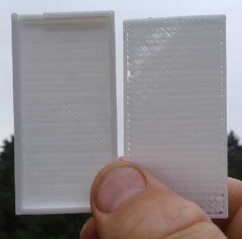 Not very porous PLA shell
What was really galling about the old printer - which will
probably be the same with the new - was you could tell it manually, or
insert at the start of a G-code file, a command to set the amount of
filament to extrude per pixel, but if the command was inserted
elsewhere in the file, eg, after printing the porous face, in order to
print the rest solid, the program would recalculate how much filament
"should" have been used and want to extrude a ridiculous additional
length right then and there as if it had been making the thicker trace
all along and "should have" already extruded all that. This results in
the print stopping with a "long extrusion prevented" error
message. Was there some way to re-initialize the length to start over?
Maybe as if it was a new print on top of the old one?
All this promised to be harder to figure out than how to
get the old printer to work again. But could I just "fudge" it? I tried
a new design. It left little channels, vertical this time for gas
bubbles
to rise to the surface, on the outside of the faces. And I only put one
layer of diagonal 'weave' on that instead of two. It was .8 mm thinner
and porous everywhere. The pores were a bit coarse and I would
definitely put parchment paper inside. [I actually picked thin PP
non-woven cloth: more open to let ions pass better.] It
looked just fine. Then I
thought of a couple more refinements around the edges: an interlocking
rim to hold the two pieces aligned plus prevent edge leakage, a broader
internal flat rim for where the edges of the cloth would have gaps.
I was still wondering what to use for a current collector
if I used salt electrolyte. Probably that urethane paint with
conductive carbon black mixed in, on a sheet of copper? Maybe I'll take
a page from the Comet airliner and round all the corners of the copper,
hoping there'll be no bare protruding corners to start corroding.
On the 31st I added the 'refinements' and made another
shell of PLA. It pretty much snapped together. On each face, a vertical
grille of
single beads of plastic spaced 2 mm, .4 mm thick, was a space for
bubbles to rise. Another single .4mm layer of diagonal beads made it a
more
solid but still "porous" layer, now .8mm thick. I'd have added a third
layer, diagonal fill going the other way (that's how the printer prints
layers of fill) to stiffen it, but it seems
to fill in the pores and make it solid.
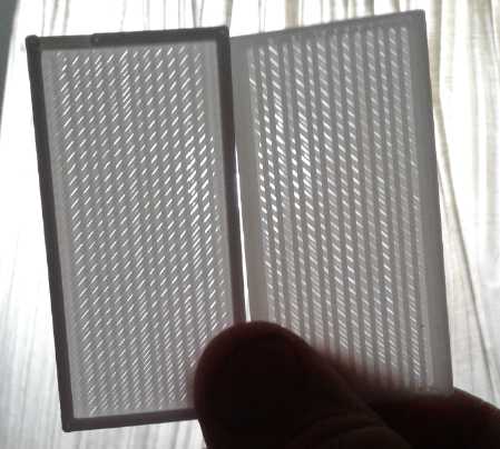
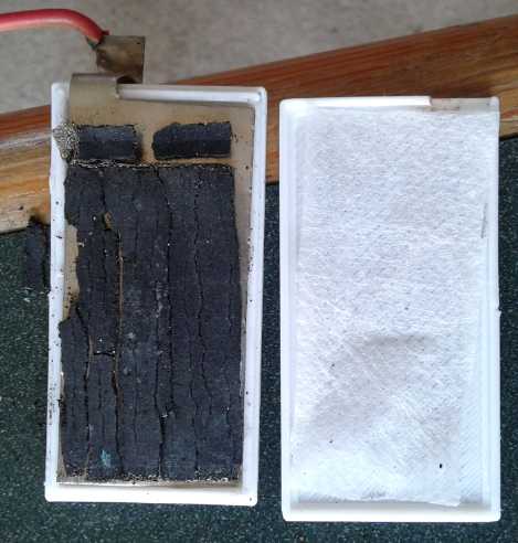 L: "Porous PLA Plastic" Shell done on new 3D
printer. (Test cell electrode size)
L: "Porous PLA Plastic" Shell done on new 3D
printer. (Test cell electrode size)
R: with cupro-nickel current collector, bits of nickel oxide electrode
from dry cell,
and a paper thin piece of PP cloth liner to prevent escape of oxide
particles.
I cut an existing piece of cupro-nickel down a bit to fit
in, and
put a few bits of dry cell nickel oxides electrode into it. Facing the
outside I used the paper thin polypropylene cloth instead of parchment
paper. It was more open to conduct ion flow better, and it was being
held .8 mm inside the surface of the shell, so unless something is
wrong, the chance of the electrode inside shorting to the zinc one
(itself encased in agar) seems slight.
I knew methylene chloride wouldn't 'glue' (liquify) PLA
(poly lactic acid) plastic. I tried methyl-ethyl ketone with almost
equally
poor results. PLA seems to print nicer/cleaner, but I would have to
switch to ABS for shells that would glue together.
Well, next month!
(30th) Load Test #4
Continued load tests would be needed to see if the zinc
electrode did or didn't deteriorate with long cycling. In the morning I
decided to try a lighter load test with 30 ohms. The cell sat at 1.769
V in the morning. It was high enough that I forgot something: I had not
fully charged it after test #3 the previous night. I was simply pleased
that it had held such a good voltage overnight. That it did so with
hardly half a charge was even better.
The voltages under load dropped fast enough to jog my
memory. Well, it would be a good test anyway: half charged down to
"empty". It was under 1.7 volts within 10 minutes, delivering 46 mA. It
ran for exactly an hour before dropping under 1.5 volts. The 45 mA-H
result showed that it held energy overnight, again proving I finally
had a real, practical battery.
Darn these load tests take time! The more successful the
cells, the longer they will take and the more tests and cyclings I'll
want to do. I'm looking more and more favorably on programming that
microcontroller.
(31st) Load Test #5
On account of the weather (finally a nice day!; why would
I work inside?) the fifth load test wasn't until the night of the 31st.
It ran a "20 ohm" load for 75 minutes, at which time it dropped under
1.5 volts and was plummeting. Current averaged about 80 mA, so that was
100 mA-H. It recovered lethargically, which again suggested that its
energy was pretty much spent.
One might hope for well over 1/2 an amp-hour from 20
sq.cm, which (assuming the zinc was the limiting factor) suggested the
electroplating should probably be made thicker. That might also
increase the maximum current drive. I wasn't being too particular as
long as the agar jell wouldn't fall off a slick surface. Also, only one
side of the zinc was in use. I doubt the rear side contributed very
much. So we might say ideally it would have had 300 to 400 mA-H - and
the same on the other side facing another nickel oxide electrode.
But it was certainly a real battery! It was already good
enough for stationary bulk storage and it can doubtless be improved.
(August 1st) Load Test #6
On the night of Aug. 1st, not wanting to proceed too
slowly, I did another load test. But it was late. I made it a 5 ohm
load - 320 mA at 1.6 volts. The voltages were lower with the heavy load
and the test barely lasted 10 minutes - really 9 - before the voltages
were plunging down below 1.5. (By 10 it was passing through 1.25 V.)
The important thing was it would be cycled and recharged,
to provide another opportunity for dendrites to short the electrodes if
they were going to do so.
The recharging current, previously starting at 100-110 mA,
this time started out at around 130 mA. It eventually dropped to around
20 as usual.
Aug. 2nd Load Test #7
This test with a fairly heavy 10 ohm load (plus other
circuit resistances as usual, apparently making it about 12 ohms) did
something none of the others did. It was averaging about 140 mA drive.
At about 34 minutes the voltage dropped under 1.6. By 41 minutes it was
down to 1.500 volts. I confidently expected it to start dropping faster
and faster as before and I started recording the figures every 30
seconds to catch the end. But instead of the usual "terminal dive", it
began a very gradual "terminal decline". It continued to lose just 16
to 20 millivolts per minute until at 61 minutes it was down to 1.197
volts, still delivering 103 mA. After a couple more minutes, at 1.171
volts, with it still not "diving", I decided it was just too absurdly
low for a 1.7 volt cell, and ended it. In 30 seconds it was back to
1.665 volts, and within 10 minutes it was back over 1.7 volts, hitting
1.725 in 18 minutes. That suggested there was still some small amount
of energy in it.
Energy delivered was about 137 mA-hours - 37% more than
the previous measured test, #5, and with a heavier load. Apparently the
cell was gaining capacity with every charge-discharge cycle. I still
don't know if this was the zinc or the nickel oxide side's gain, or
both. I rather suspect the chunks of nickel were forming better
connections with cycling. After all, zinc is theoretically 820
amp-hours per kilogram and nickel oxyhydroxide is only 289. And that's
in theory - I understand 90-100 is a realistic figure. (A correspondent
said he was getting 110 - great!) I don't know what a "realistic"
figure for zinc is, but it's surely much higher.
Regardless If the
cell continued to last, the improving readings bode well. The zinc
either had or was gaining toward good charge capacity.
Recharging started at around 150 mA this time, and the
current dropped more slowly, commensurate with a higher capacity cell.
If it recharged well after test #7 [it did], it would have outcycled
all
my previous cells.
Aug. 3rd Load Test #8
This test was again with a 10 ohm load (again about 12
ohms total). It was very similar to test #7 with voltages a few
millivolts higher for most of the test, dropping through 1.600 volts at
about 37 minutes and 1.500 after 45 minutes. In the last 15 minutes it
dropped off faster, probably owing to having delivered a bit more for
most of the test. I stopped at 60 minutes which was also when it
dropped under 1.200 volts.
It averaged about 142 mA drive for 45 minutes, and maybe
116 for the last 15 minutes for an estimated/calculated total of 135.5
mA-hours. It would seem the limits to the capacity gain are approaching.
In 30 seconds it was back to 1.666 volts, and in 4 minutes
it was back to 1.705 volts. There was no doubt just a bit more energy
still in it from not flogging it the few more minutes of test #7.
(Aug 4th) Charging current was up yet again, starting at around 190 mA.
After charging instant short circuit current was up to about 3.75 amps,
then 2.5 dropping to 1.75 after 10 seconds.
Aug. 4th Load Test #9
I decided to pick a lighter load this time, but as I
didn't want the test to run for hours I made it 15 ohms. That seemed to
be about 17.3 ohms total circuit resistance, as it was delivering
exactly 100 mA at 1.73 volts. It was 30 minutes before it dropped below
1.7 volts instead of 10 minutes. Again I ran it until it droped under
1.200 volts. It hit 1.7 V after 30 minutes, 1.6 V at just over 2 hours,
1.5 V after 2 hours 23 minutes, 1.4 V at 2h33m, 1.3V at 2h44m and 1.2V
at 2h54m. (So much for it not running for hours! I was glad I started
it earlier.)
Current delivered averaged about 99 mA for the first hour,
95 mA for the second hour, 90 mA for the next 30 minutes, and 78 mA for
the final 24 minute decline. This added up to 270.2 mA-hours. Being
over 1/4 amp-hour in this small cell with its rather thin 'fuzzy'
plating on the zinc electrode - and probably(?) not actively using much
more than one face of the electrode - must be some sort of milestone.
Even if it got no better, it was getting into practical range for
producing stationary storage batteries.
But both faces should then make it over 1/2 an amp-hour,
and the full size electrodes are 4.5 times more surface. So counting
both faces they would have at least 2-1/2 amp-hours each -- and I would
electroplate them more thickly and evenly, so they would have more.
The test must have used most of the available energy as
recovery was very sluggish, taking 20 minutes to hit 1.700 volts again.
Recharging current was higher again, starting out at 210 mA and again
staying higher longer.
When it was fully recharged instant short circuit current
hit 4.01 amps: 211 mA/sq.cm. That was great current flow. After 10
seconds it was down to about 1.8 amps, still 95 mA/sq.cm. Then driving
a 1 ohm resistor (apparently 1.2 ohms total) it dropped almost
immediately to 1.04 volts, but it stayed over 1.00 for 2.5 minutes
delivering just under an amp, about 45 mA/sq.cm. Real performance!
Aug 5th: Take Apart
I decided I couldn't leave y'all in suspense for another
month, and I took apart the cell to inspect the zinc electrode. The
agar still coated both faces. It still had the same milky white color
(with the samarium oxide), and it still had the same feel of
jelled agar. It didn't seem to be deteriorating. That much made it a
success in principle.
What wasn't good was a lot of rough zinc poking out all
around the
edges. And it
seemed to have started growing a few dendrites at those edges. My take
on that is that after dipping the plate in the agar, as it cools and
jells it shrinks back a bit and leaves the sharp edges exposed. So some
extra needs to be painted on around the edges afterward to ensure it's
all completely encased.
The idea works. "Everlasting" zinc electrodes having good
current flow and energy storage appear to be possible and practical.
The agar protects the electrode from the electrolyte and the octavalent
osmium doped film somehow helps the ions to pass freely through the
agar to the zinc surface. (The amount of rare and costly osmium needed
is very minute.)
http://www.TurquoiseEnergy.com
Haida Gwaii, BC Canada