Turquoise Energy News #135
covering
August
2019 (Posted September 7th 2019)
Lawnhill BC Canada
by Craig Carmichael
www.TurquoiseEnergy.com
= www.ElectricCaik.com
= www.ElectricHubcap.com
Month In "Brief"
(Project Summaries etc.)
- "Charge the Future" Challenge
In
Passing
(Miscellaneous topics, editorial comments & opinionated rants)
- Third Stage Democracy
- Truth and Truthfulness - The Epstein Saga - Rational and Irrational
Numbers 10-99 - Small Thots - ESD
- Detailed
Project Reports
-
Electric
Transport - Electric Hubcap Motor Systems
* Ground Effect Vehicle ("GEV")
Other "Green"
Electric Equipment Projects
*
Some more Handheld Bandsaw Sawmill Notes
Electricity Generation
* Wind Power: 5 Blade Windplants Better Than 3?
* My Solar Power System: - Monthly
Solar Production log et cetera - Six month summary, notes.
Electricity Storage
Turquoise Battery Project (Mn-Zn or Ni-Zn in Potassium
Hydroxide electrolyte ?)
*Re-agaring the zinc electrode - More Research Needed - The real reason
all my NiMn cells had high self discharge - Painting Parts of
Electrodes to Prevent Gas Generation - Making Nickel-Manganates '+'
Electrode - Tentative Procedure for Making Positive Electrode (Aug 22nd
2019) - "Kneader Reactor" - FWIW: Cupro-Nickel as Alkaline "+" Current
Collector -
Electrode Powders Compactor: Pneumatic-Hydraulic Bottle Jack -
Commercialization and the "Charge the Future Challenge"
Even more than July, August
came to be about battery development experiments and tests. Inevitably
there's not much other news as everything else got left behind.
In addition to the exciting recent battery research
developments
already, there was the prospect of funding to commercialize long or
everlasting life, low cost, nickel manganate-zinc batteries. The
assurance and detail with which I could write, and perhaps the odds
of getting funded, would increase by the percentage of everything that
was
already working when I applied, which had to be by mid October.
Charge the Future Challenge
As soon as I had TE News #134 out, I turned my attention
to applying for Natural Resources Canada's battery challenge. Unlike
the dysfunctional IRAP and STDC funding programs for which the biggest
qualification to qualify for funding is to have lots of money already,
this one had no specific requirements for having other funding. It also had a line for
a cash equivalent value of "in kind" support by the applicant and
by others. If working for over a decade unpaid and having spent tens of
thousands of dollars for equipment and materials, and being quite
prepared to contribute all - and space - to the cause, isn't "in kind"
value,
I don't know what is. Obviously without it I wouldn't be about ready to
make new technology batteries and there would be no application. Of
course batteries hasn't been my only and full time project, but the way
forward now is to get others involved, for which money is required.
I found my friend Mike K. was very enthusiastic about it,
and he's had a lot of experience running production businesses. His
readiness with specific ideas for how to get rapid production going to
perform critical tasks give me great confidence we'll succeed. We
talked about the amount of money to ask for. He said I was asking for
too little. that trying to do things too cheap ends up wasting a lot of
time and costs more in the end, and that everything takes longer than
you think it will - which I can only agree heartily with. And that
being a government program they would expect people to spend lavishly.
OTOH asking for a lot more than is required will probably end up
looking self-serving which might be counterproductive later.
In the battery developments of this summer, many things
which
had seemed to be side tracks in previous years, which hadn't led to
working batteries then, nevertheless started coming back as being
useful to developing, improving or producing the present working
batteries, more and better things than would have been possible without
all this accumulated knowledge.
During August I tried to make a couple of nickel-manganate
electrodes, but they didn't seem to work very well. They should have
higher amp-hours per weight, but if I can't get them going I can always
fall back on regular nickel oxyhydroxide electrodes, or manganese
dioxide. So failure in this direction isn't a project killer.
I ended the month going to a camp-out with a group of
friends and seeing my mother, who lives near the campground. But it's
sure costly getting in and out of the BC north coast.
It's great to see things happening in electric transport.
Here are a couple of pictures.
 EV Bus spotted in Vancouver BC by Tom
Sawyer
They're coming, gradually!
 Tom also found electric trucks (left)
for sale on line, dirt cheap.
A mutual friend bought two of them and got one running. It seems
a shame that they need minor electronic work, but almost no one
knows how to do it so they're mostly going to waste.
In Passing
(Miscellaneous topics, editorial comments & opinionated rants)
Third Stage Democracy
Unless stopped, immoral actions by a society's leaders
will get bolder and bolder over the years and decades until the society
collapses. Civilizations spring up from relatively unorganized liberty,
then
leaders want more and more power and control over the citizens over
several generations
until people effectively become slaves who can't thrive and there is
collapse, usually with great depopulation. How many
civilizations have come and gone on this planet, at least for tens of
thousands of years if not hundreds? Violent revolution may
be necessary to win democracy, to wrest control of governance from
those who will not yield power. Even then formation of a democracy is
not assured as we have seen - it depends on those who become powerful
in the revolution wanting it and instituting it.
Once democracy has been established, change of power if
nothing else occurs peacefully. Democracy is the only form of
governance capable of adapting and growing as conditions change. But if
power is effectively seized by an immoral oligarchy of the increasingly
rich and powerful, if public choices are between Tweedledum and
Tweedledee who are both beholden to that oligarchy for their place,
democracy becomes a facade. If people find there is no way to maintain
or regain liberty and freedom in their lives, where might they turn but
violent revolution? And if there is violent revolution in a democracy,
it can only be to return to some form of dictatorship, which will
usually last at least several generations. ("They tried democracy. It
didn't work. It broke down.") Violence must be avoided at all costs.
Dialog is the way forward.
An oncoming great global depopulation is becoming
increasingly visible. Bizarre and unprecedented weather patterns are
devastating crop production and ranching worldwide and wreaking havoc
to infrastructure. The oceans seem to be virtually fished out, and per
latest findings it looks like a 3 meter (10 foot) sea level rise will
be astonishingly rapid, displacing gigantic populations. Species are
daily becoming extinct. The now global "ponzi scheme" financial system
is collapsing. When people can't afford scarce food they become
malnourished and easily susceptible to some epidemic, which with modern
travel will quickly become a pandemic.
But in this global catastrophe is opportunity for
humanity. People who would never have considered allowing (much less
promulgating) change will become far more open, perhaps even proactive,
when their own mortality is suddenly in question and it is clear that
things are already rapidly changing, one way or another, for better or
for worse; that their "status quo" is gone. With population reduction
today's competition
mentality will change to co-operation as everyone is needed to keep
modern technology and communications from collapsing. Workers'
conditions will greatly improve when corporate competition is how to
attract and keep them.
Everyone still
around by the end (around two billion?) will be saying "Well, that
didn't work." and asking "What went wrong and how do we do it
differently this time?"
Along with environmental sustainability and population
management, we must start restructuring our societies, all our social,
economic and political institutions and organizations from the family
up to attain Social Stability, then Social Sustainability which will
never break down. We need to move to a "Third Stage Democracy" where
concerned citizens form 'Social Sustainability Design Teams' to work
out solutions to each problem, in accordance with the core values of
Life, Equality, Growth, Quality of life, Empathy, Compassion and Love
for humanity. The consensus of such solutions is then passed to elected
government for enactment. Those in power today might resist efforts to
establish such a principle and practice of grassroots power by the
elite of the common citizenry, but future leaders will see that it is
in everyone's best interest. (Apparently the beginnings of such teams
are already happening in Sweden, with government sanction or
sponsorship, so the idea isn't entirely "pie in the sky".)
In the meantime, if I myself do start a company to make
batteries and perhaps other electric transport products, it must first
of course be self sustaining, but otherwise I will attempt to organize
it along new lines in accordance with such principles.
I have never understood why democratic forms and habits
are never established within companies - or even in government/civil
service work environments when the government is supposed to be
democratic. You can elect your national political representative, but
you're not qualified to periodically elect your own shop supervisor? -
he must be chosen by someone "in authority", and once chosen, good or
bad, and even in the face of some new person better qualified or with
talent and great ideas coming along, he's there until he retires and
until then no one else is allowed a chance.
Truth
and Truthfulness
One must be aware of the difference between teaching "the
truth" and teaching "truthfulness". When a truth/fact like "Pi
equals 3.14159" is taught, there is no dispute. There is no need to
argue the merits of using this particular number over any other number.
There is no need to pass a law to force math teachers to not teach that
some other number is pi, or that pi is a meaningless number.
Many other matters are not so concrete and there is room
for varying opinions. When one teaches for example that "capitalism is
better than communism", there may even be differences of opinion on
what those words mean, and what the speaker feels these words represent
could change the statement from true to false for him, or for different
listeners, with any number of shades of gray in between. But there have
been laws passed for, or in the old Soviet union against, teaching this.
One might truthfully believe the statement is true or
false. But it is an opinion, not a fact. A more truthful thing to say
might be that "Most people in this country think that...", and also to
try to define the two words. By far the best thing to teach the student
is how to think for him/her self. (...instead of in effect telling
him/her that other people have already done the thinking for them and
they should simply believe it's the truth on faith.) There are no laws
specifically forbidding teaching students how to think, but there are
usually any number of ways, including laws, that it is discouraged. The
state does not want the current "status quo" questioned. Why, something
might be changed!
It would not be amiss to feel that the state should stay
out of defining educational content beyond the very basics of reading,
writing and arithmetic. Young people - like most people - like to
learn. Beyond such basics young people should be free to learn what
interests them, rather than a set curriculum which is perhaps "ideal"
for the "average student" but not suitable for any student in
particular.
This is just one of a number of subjects related to clear
and critical thinking on social issues discussed at much greater length
in Skeptical Essays by Bertrand Russell. (Russell himself
especially resented having to learn Latin, "a language that nobody
speaks any more", in school. BTW I think the title gives little away
about the contents... an "essay" to me is a school English class
assignment, and "skeptical" has the connotation of negative thinking to
my mind, when the book as actually full of papers related to "critical
thinking" on social issues.)
Writing almost 100 years ago in the early to mid 1920s,
Russell hits upon many of the evils which started perhaps with the
industrial revolution or before, and which have only - as he predicted
would happen if no action was taken - become more exacerbated in the
intervening century. (Indeed he seems to have loosely predicted most of
the future century - even the alignment of forces involved in what
became "the cold war" - short of the rise and fall of Nazi Germany,
nuclear weapons, and much further on, computers and the internet.)
Perhaps it's time to look at corrective actions for the
social problems and failings he so clearly identifies. After all, it's
not the things civilizations do that cause them to fail, it's doing
nothing and letting wrong thinking and dysfunctional methods fester and
grow over generations until they overwhelm reality.
The
Epstein Saga
First Jeffrey Epstein is
arrested for child sex and human trafficking, after flaunting it in
everyone's face for most of his life. (Arrested again... after getting
off with some sort of "plea deal" years ago that no lesser placed
person would have got, instead of being forcibly removed from the
planet. The judge that signed that deal has just resigned.) Since he's
the "king" of it all, and since it's known that he knows everyone
involved at all the highest levels [of depravity], everyone starts
speculating how many rich, famous and even royal persons will be named.
Then it starts circulating on youtube that because he
knows so much about so many highly placed people, he'll surely be
murdered before he can testify - and that they'll surely say he
committed suicide. A week(?) later, amid some very strange anomalies in
the workings of the prison system (especially for such a high profile
prisoner), Epstein "commits suicide." This time the "conspiracy
theories" preceded and predicted the actual event.
And even with all that suspicion even well in advance of
the event, the bought-off 'main stream' media makes no suggestion that
it was anything but: It wasn't "apparently by suicide", "said to be
suicide" or "alleged suicide" or "was found dead". All the stations
just said "Epstein committed suicide." And why did no one say how it
was done? Did he "hang himself" with a bedsheet (for "plausible
deniability" of murder), or was it one of those "three bullets to the
back of the head" sorts of suicide? The guards were said to have been
asleep(?...or did it for pay or were blackmailed?... who else could get
in? They were uncooperative with investigators.) and people had heard
screams coming from Epstein's cell.
A couple of days after I wrote the above, the coroner
reported that the broken hyoid bone in the throat was usually (not
invariably) indicative of homicidal strangulation rather than suicide.
Combine that with the screams... Oops! (Hilarious! As usual the MSM is
caught looking like either idiots [Hah!] or bald faced liars spouting
fake news.) But it must be noted that evidently one of the usual worst
offenders, the Washington Post, broke the coroner story. It could as
easily have promulgated the same lie as the rest of the media and kept
quiet about the coroner's report, which would then only have been
circulated among "conspiracy theorists" on youtube and on zerohedge.
Yay WaPo! Maybe things are changing?
Rational
and Irrational Numbers 10-99
In French, numbers from 20 to 60 follow a logical pattern
(I must use it as an example because it's the only other language I can
count above 4 in. I definitely don't guarantee my spellings, either.):
20 Vingt
30 Tronte
40 Quarante
50 Cinquante
60 Soixante
Above that the system breaks down, reminding one somewhat of
Roman numerals:
70 Soixante-dix (sixty-ten)
80 Quatre-vingt (four-twenty)
90 Quatre-vingt-dix (four-twenty-ten)
(I don't understand why they wouldn't use
70 Septante
80 Huitante
90 Neuvante)
In English we fare better:
20 Twenty
30 Thirty
40 Forty (Fourty)
50 Fifty
60 Sixty
70 Seventy
80 Eighty
90 Ninety
The numbers from 10 to 19 are another case. In both languages they
start off irregularly with a single word as if they were another single
digit number:
10 ten / dix
11 eleven / onze
12 twelve / douze
In French this continues:
13 trez
14 quatorze
15 quinze and then I think it's:
16 seize (but I'm not sure of that, It could be dix-six, ten-six)
finally the few remaining:
17 dix-sept (ten-seven)
18 dix-huit (ten-eight)
19 dix-neuf (ten-nine)
In English the rest of the numbers after 12 are called the "teens",
which follow a strange reverse pattern, thir-teen (three-ten),
four-teen, ... , nine-teen. If we wanted to rationalize them, however,
we run into a bit of trouble. "tenty-three" just sounds too much like
"twenty-three" and would be bound to be misheard occasionally.
Mishearing numbers can have bad consequences. We'd have to drop the
standard "_ty" ending.
We could turn the teens around and add "y": teeny-three, teeny-four,...
, teeny-nine. These should be fairly easily to understand even if the
hearer hasn't heard them before. Of course, "teeny" by itself has
another quantitative meaning. But if shortened to "tenny-three",
"tenny-four"..., again it sounds too close to "twenty". That might
leave the shortest and perhaps the most obvious: "ten-three",
"ten-four"..., "ten-nine" ...which could actually work. It does in
French.
(Hmm... or how about "tenna-three, tenna-four, tenna-five...")
Or we could just leave it the way it is. We managed to learn it and we
never think about its oddness, why should future generations have it
any easier?
Small
Thots
* Duralex Impact Resistant, Tempered Glass Drinking Glasses -
Info Update. As soon as he got my last newsletter my friend Rick
Peterson sent me a
page from Amazon.ca, a search for Duralex glasses. They have been made,
in France, since 1939! There were many selections - far more styles,
sizes
and colors than were (rather briefly) available in Canada in the 1970s.
Sometimes I remember one can find most anything on line these days,
sometimes I don't think of it. I ordered a set of four 8.75 oz glasses.
It's just taken
an extra 42 years. I still think their absence from store shelves is
deliberate - to keep people buying easily broken glasses, again and
again.
Whether this is a distributor's or individual stores' idea or both is
less
certain.
* A piece of fuzzy logic that causes so much trouble in the
world: "I can think, therefore I am right."
* I am SO good at losing or misplacing things. I decided
(having been out for a couple of months) that it was time to make
another batch of white wine. (Last batch was August 2017.) I went to
the coat closet and got out the
primary fermenter bucket, lid and the hydrometer. Where was the
long-handle stir spoon? Nowhere to be seen. I checked another closet.
Nope. I went back to the first closet and in a space of no conscious
thought, I leaned into it and reached my fingers around the door frame
to
the right - a tiny space only 2 inches wide, surely too small to hide
anything - and felt the handle of the spoon, standing there utterly
vertical. I
would never have found it by looking. I might almost say I'd never have
found it by myself.
This isn't the first time something like this has
happened. I remember the first time I became consciously aware of
finding something this way. Back in Victoria a few years ago I was
missing a car key. Not urgent. A day or two later I was wandering
around the house for some reason, and without any conscious thought, I
suddenly "snapped awake" as I found myself standing facing sideways in
front of a narrow set of open shelves along the side of the kitchen
doorway, staring at the "missing" key in an ashtray on a shelf.
One can only give thanks to one's guardian angels for
their guidance as one tries to live in harmony with the unfolding of
the universe.
* Perhaps if one buys "tall telephone pole" variety peas, one should
put up 6 foot tall pea netting instead of just 3 foot. (I used chicken
wire.) Predictably some of these stems folded over as they grew taller
and as the peas grew heavier. But I must say I've had a much better
crop from these (in spite of the short netting and the cloudy summer
with generally poor vegetable harvests) than from any other variety
I've grown in recent years. I have almost a pound of them in the
freezer besides all the ones I've eaten - mostly raw. Mmm, garden peas!

 "Tall Telephone Pole" variety Peas, two short
rows (left planted earlier), August 13th
ESD
(Eccentric Silliness Department)
* Yeasterday: When the dough rose from the dead, so there's fresh bread
and buns today.
* An engineer runs a boring bar, but his clients are never bored. Only
pieces of metal are bored. On a lathe. Bored stiff.
[from my high school Chemistry teacher, 1971... I think
there were three, but I don't remember the other one.]
* BaNa2 : Some students (who had apparently learned
something)
howled that that is an impossible compound - all cations and no anions.
The teacher replied that it was very important in the diet of
anthropoid apes.
* BaAuH2O : Probably only the elders might remember this guy
now**.
* Cipate: unforeseen, unpredicted, a surprise, to not see something
coming. (opposite of Anticipate.)
** Barry Goldwater
"in depth reports" for
each project are below. I hope they may be useful to anyone who wants
to get into a similar project, to glean ideas for how something
might be done, as well as things that might have been tried or thought
of... and even of how not to do something - why it didn't
work or proved impractical. Sometimes they set out inventive thoughts
almost as they occur - and are the actual organization and elaboration
in writing of those thoughts. They are thus partly a diary and are not
extensively proof-read for literary perfection, consistency and
completeness before
publication. I hope they add to the body of wisdom for other
researchers and developers to help them find more productive paths and
avoid potential pitfalls and dead ends.
Ground
Effect
Vehicle
(first
the
R/C
Model)
On the 14th I needed a bit
of epoxy. I make a bit extra and cut a piece of the thin PP cloth to
cover the bottom of one of the hulls. But the 20 grams of epoxy only
glued it down for about 1/3 of the way from the back. It would need
another 40+. And (as I
expected) it didn't visually cover things over. Every irregularity
showed, and the writing on the foam showed through. A thin coat of
spray paint later could help, but I
started sanding the foam cuts and the joins much smoother.
That was as far as I got. I can't believe the whole summer
has slipped by without finishing the model and trying it out. But the
battery research has taken precedence.
Other
"Green"
Electric
Equipment
Projects
Handheld
Bandsaw
Sawmill
Notes
The saw didn't seem to be
cutting at all well. I should have been dicing up the big log into
cants with the chainsaw mills, but I was too busy with battery
development to cut much anyway. It became evident that the big log was
going to sit until September. I ordered 5 new bands and awaited their
arrival.
They came on the 17th. I put one on and started cutting
the 8" wide x 5' long spruce cant into 1" x 8" boards. Is spruce hard
to mill? I ticked off the seconds that I had the saw trigger pressed
with my tongue. I'm
very good at that, and I'll say I should have been well within 10%. The
time for each cut in seconds was roughly:
52, 63, 75, 75, 86, 100, 88, 89, 120. I sharpened the band. As best I
remember the next ones took something like: 75, 90, 100, 88. Then I
stopped
counting.
The times show how the band dulls quickly cutting spruce.
and
the 8" width seems much harder than 6". On the last board the band hit
a knot hole full of sap 1/3 of the way along. The band and wheels
gummed up, and I had to wedge the cut end open to un-jam the saw. After
I picked up the board and tossed it with the others, the palms of my
hands were likewise thoroughly wet with sap/gum. I went inside to clean
my hands with varsol. After I finished these two little cants I had
another whole large log to mill and get off my lawn. (I got it started
in early September.) After that, I hope
I can do some alder instead, or some other tree specie.
I did finish them - 24 more 1"x8" x 5' boards, with the
new band getting sharpened once. Only the very first cut with the brand
new
band was under 60 seconds. Naturally I wish they were all that fast,
but I don't know how to achieve it. The automatic band sharpener isn't
bad, but I had to modify it myself to do finer toothed bands, and I
note that it flattens the angle of the tooth a bit behind the cutting
edge. Perhaps that's a reason they aren't quite as good as new after
sharpening.
Again I would note that spruce is tough stuff to mill, and
that 6" wide boards cut twice as fast as 8". I think the wide cuts have
just too
much drag on the band as it goes through the wood, even without
cutting. I cut alder up to 12(?) inches, a whole small log with (as
best I recall) one band sharpening if any. I don't think I'll make any
more 8" wide spruce cants to be cut into lumber. (I can probably use
some 2"x4"s for interior walls. Those should go pretty easily.)
Wind
Power: 5 Blades Better than 3?
 Jim Harrington pointed me to a 5-blade wind turbine (horizontal axis)
link from BangGood.com . There was a question/discussion space and
someone asked why 5 blades, and someone answered it. Apparently the
slower turning 5 blade types are quieter than 3-blades, and in light
winds deliver up to around 60% more output. Here I had always
understood that 3 blades was "the ultimate"... but apparently that's
only in sufficient wind.
Since a chief objection to (3-blade) windplants is the
noise, and since winds are far more often light than strong, I decided
to swallow my gradually improving ideas for making a VAWT (like I have
time anyway?) and try one of them. It is on order.
Another point was that the extra air friction of 5 blades
in heavier winds reduces over-revving. But I do wonder what will happen
in a really heavy gale.
I don't understand why no one seems to use Hugh Piggott's
fabulous tail design. The propeller is slightly off center compared to
the pivot axis. As the wind strength exceeds safe limits, the
increasing off-center pressure on the propeller causes the weighted
tail to climb up a ramp and pivot, allowing the off center windplant to
turn away from the wind, until it can be almost sideways to it in
powerful blasts. This prevents the unit from over-revving and
over-powering. As the wind lightens, the tail swings it back into the
wind. The tail weight and the ramp steepness governs the process, so
there's nothing to wear out and start changing the response.

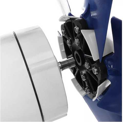
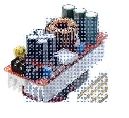 The output of the windplant was rated as 24 volts. That wouldn't do for
charging 36 volt batteries, so at the same time I ordered a DC to DC
up-converter of substantial power, also at BangGood, to bring it up to
about 40 volts.
My
Solar
Power
System
Month of August Log of Solar
Power Generated [and grid power consumed]
I decided to log daily power for at least one more month
and have a half a year's data. But I'd be away camping with friends the
last week.
(All
times are in PST: clock 48 minutes ahead of sun, not PDT which is an
hour and 48 minutes ahead. DC power readings - mostly the kitchen hot
water heater - are reset to zero daily, while the others are
cumulative.)
Date House solar KWH(Grid+DC), +Trailer Roof solar KWH - day
total KWH
made [power
co. meter readings] weather, usage...
July 31st 49.85+.53, 629.39 - 14.46 [67202@ 20:30; Br.Heat] Early:
rain,
Most of day: Sun w. scattered clouds, very light haze, no jet trails.
---
August 1st 57.62+.53, 634.98 - 13.89 [67207@11:00; bath; 67208@21:00]
Mostly Sunny, no jet trails. Forgot I had turned 2 inverters off
previous evening, until late morning.
2nd 66.90+.44, 641.21 - 15.95 [67213@20:30] Sunny
3rd 75.19+.43, 646.98 - 14.49 [55Km,chj.car slow(oops, into
evening); 67222@20:30] Mostly sunny
4th 84.59+.52, 653.39 - 16.33 [55Km,mor car chj.@1500W; bath;
67233@20:00] Sunny, warm day for the Tlell "Fall" Fair!
5th 91.79+.45, 659.80 - 13.76 [finish car chj; 67240@21:30]
Sunny. Oops, left the 2 grid ties turned off again. (Wouldabin ~16 KWH)
6th 100.86+.55,666.03 - 15.84 [bath(solar!); 67246@23:30] Lo &
behold, another sunny day!
7th 104.74+.51,668.77 - 7.13 [55 Km,3.8 KW chj.;
67258@21:00] Overcast! (Summer iz over? but, but... ther wuz sun in QC!)
8th 108.00+.50,671.08 - 6.07 [67262@20:00] castover
9th 111.57+.59,673.56 - 6.64 [85Km,Chj.car@3.8KW; Laundry;
Chj.someone's Chevy Bolt @3.8KW(~45 KWH?) and, 44Km,chj.my car
again@1500W 67295@20:00; 2 cars still charging; 67313@23:00] abovecast
10th 116.63+.50, 677.22 - 9.22 [BR heat, 2 car fini. chj. overnight;
67355@8:30; 55Km,chj car@3.8KW; 67367@22:30] overcast, w. sunny breaks
AM.
11th 120.93+.42, 680.31 - 7.81 [67372@10AM; 67373@20:30] light overcast
12th 123.50+.42, 682.17 - 4.85 [67371@20:00; bath] Heavy overcast &
(gasp) Rain! (A tourist said it was sunny most of the day at
Masset/North Beach!)
13th 132.37+.49, 688.39- 15.58 [55Km,part Chj.car@1500W; 67392@21:00]
Sunny and warm. (what a contrast!)
14th 141.23+.43, 694.58- 15.48 [Finish chj.car@1500W; 67397@21:30;
bath] Sunny and warm.
15th 144.77+.49, 697.15 - 7.60 [40Km,chjd.@1500W; 67409@19:00]
overcast.
16th 147.47+.59, 699.30 - 5.44 [85Km drv,chj.@1500W (not much
solar); 67426@21:00] overcast. 2 inverters (4 250W panels) were turned
off 2/3 of the day.
17th 153.16+.53, 703.31- 10.23 [55Km,chj@1500W; 67444@20:00] Sunny with
drifting clouds.
18th 161.90+.45, 709.41- 15.29 [67450@21:30] Sunny & warm.
19th 163.90+.61, 711.12 - 4.32 [Laundry; 67462@21:30] Cold &
wet. Clouds - light - heavier & finally torrential rain over the
day.
20th 164.66+.45, 711.76 - 1.85 [55Km,chj'd@3800W; bath;
67478@20:30] Overcast, wind & rain. I had to turn 2 inverters off
so those panels could feed only the kitchen hot water tank, which they
barely did with minimal hot water use. (Someone got a sunburn in
Vancouver area today.)
21st 4.46 + .64, 715.21 - 8.55 [50Km&chjd.@1500W;
67491@20:00] Alt. sun & clouds. Power bump in night - meter reset
itself
22nd 6.18 + .48, 716.60 - 3.59 [bath; 67500@20:00; BR heat]
Clouds & rain. This is summer?
23rd 12.66+ .42, 721.21 - 11.51 [67508@19:30] Clouds and some sun.
On Holydays, returned Sept. 2nd.
Sept.
2nd 69.46+.71, 759.99 - 96.29 (10 days) [67543@20:00] Sunny until late
afternoon.
3rd 71.99+.51, 762.06 - 5.11 [55Km:chj.car1500W;
67558@20:00] Overcast, later rain. Not much solar for car!
4th 1.98+.32, 763.73 - 3.97 [76568@20:00] Part
Cloudy AM, Sunny PM. I turned off the inverters and unplugged them
while the electric line crew were working replacing the power pole
& transformer outside (~10:30 - ~14:30), so the day's collection
was way down. And of course the power break reset the one meter so
earlier AM collection recording was lost. During the outage I moved the
two panels on the lawn in order to mow the lawn. They had also been
more and more in the lengthening tree shadows until mid day, and the
new position should be a little better for the autumn.
5th 6.24+.52, 766.76 - 7.81 [55Km,chj@3800W;
76582@19:00] Mostly overcast.
6th 8.55+.53, 768.77 - 4.85 [85Km,chj@3800W; 76604@19:00]
Mostly overcast, rain. 2 inverters were off quite a while.
7th 13.42+.46, 772.27 - 8.83 [laundry; bandmill; 76618@19:00] AM
overcast PM sunny periods.
Daily-
KWH- # of Days (August)
Made
1.xx - 1
2.xx -
3.xx - 1
4.xx - 2
5.xx - 1
6.xx - 2
7.xx - 3
8.xx - 1
9.xx - 1 (9**)
10.xx- 1
11.xx- 1
12.xx-
13.xx- 2
14.xx- 1
15.xx- 5
16.xx- 1
** The "9" days includes the 8 days of August pro-rated average of the
10 days I was away.
Monthly Tallies: Generated KWH [Power used from grid KWH] ("April 0"
starts
March 31 after solar hours.)
March 1-31: 116.19 + ------ + 105.93 = 222.12 KWH [786 KWH - used from
grid]
April - 0-30: 136.87 + ------ + 121.97 = 258.84 KWH [608 KWH]
May - 0-31: 156.23 + ------ + 147.47 = 303.70 KWH [543 KWH] (11th
solar panel connected on lawn on 26th)
June - 0-30: 146.63 + 15.65 + 115.26 = 277.54 KWH [374 KWH] (36V, 250W
Hot Water Heater installed on 7th)
July - 0-31: 134.06 + 19.06 + 120.86 = 273.98 KWH [342 KWH]
August 0-31:127.47 + 11.44 + 91.82 +(8/10)*96.29 = 307.76 KWH [334 KWH]
(12th panel 'installed' on lawn Aug. 1)
6
month total March 1 to August 31: 1643.94 KWH made; [2987 KWH consumed
from grid]
Things Noted
* With the 12th panel added, [estimated] August solar power production
beat all
previous months, slightly above May. Tree shadows definitely got longer
and reduced the light as the month went on, especially to the two
panels down on the lawn. (Not to mention the garden.) Soon they'll be
hitting the house roof too.
* The August total assumes 8 days of the 10 I was away at the average
of those 10 days, 9.63 KWH/Day. (The other 2 days were September 1
& 2.)
* Power on fully sunny days in August with the 12 panels (~3440W total)
seemed to be just under 16 KWH near the start of the month, dropping a
bit as the month went on. And mostly either it was sunny or it wasn't -
there were few "mostly sunny" days giving close to full output.
* Cloudy days averaged perhaps a little under 8 KWH from the 3440W of
panels - around half of what sunny days give. That didn't stop a few
rainy days from having very low output. Again at present prices it
seems worth it. If we weren't get electricity at a subsidized rate
here, the economy over diesel would be large and obvious.
* Power going to the grid isn't counted by the utility company meter -
it won't run backward. But since the power generated and used in the
house does subtract from that used from the grid and slow down or stop
the meter, the total consumption is somewhere between the grid power
and the grid power plus the power generated. (Depending how much the
grid was being subsidized - probably not very much except on sunny
days.)
* For the 6 months of spring and summer, on average about half as much
solar power was made as was used from the grid. So comparing power
generated to that used from the grid suggests that twice as many solar
panels (20-24 instead of 10-12) would be required to make the house
"power neutral" in spring
and summer (and early autumn) but the situation is complicated by not
knowing the total consumption.
Four or five winter months will have
much less collection (not to mention far heavier power usage). I really
ought to raise the tops of the
panels to get them to a steeper angle, since at only 15° south
slope they'll get less than half power in December. Even in June
30° would be an improvement and at winter solstice would give 70%
output instead of 50%. At 45° they would be weighted well for
spring and fall while still giving 86% in winter (short days anyway,
and except in very favorable locations full of long shadows too) and
97% in
summer.
* On sunny days during the summer more solar power was usually made
than the amount consumed from the power grid. Much less power was used
from the grid was when I was away on holidays. (No EV car charging,
etc. I unplugged the kitchen solar hot water. Hmm, I could have turned
off the main water heater, too.)
* Months that had sunny days (March, April, May, August) had better
collection than those that didn't (June, July), yet the totals
generated in the cloudy months were not so much lower than the better
months. Of course, in June and July the sun was highest, so they had
the potential to exceed any other months if they had had more sun. So
perhaps we are measuring ~275 as against ~350 if the weather had been
nicer,
or even more had most of the days been sunny.
Improving the System
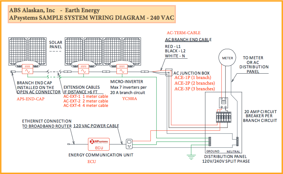
I decided to improve the grid tie arrangement and get it
inspected, with some 240 volt wired-in grid tie inverters. In some ways
it seems a little silly, since the plug-in grid tie inverters work
fine. They also cost 75-150 $C for a nominal 1000 W - but which rarely
give over 850 or so.
The "AP" wired-in grid ties I'm planning on getting have
four separate panel inputs (that's a slight improvement) and are rated
at 1200 W (also somewhat better). Since they will be wired into the
circuit breaker panel one can't read the power figures directly.
Instead one buys a communications unit that can be connected to a
computer or to WI-FI. The costs add up: Inverter 500 $ each, comm unit
350 $, double circuit breaker and wiring maybe another hundred,
bringing it to almost 1000 $ plus the panels. Hmm... I may have just
talked myself out of it for now. 100 $ and "plug it into an outlet" is
a lot cheaper and easier. Anyway here's a sample circuit/wiring diagram
(with 2-panel inverters, from the web).
Electricity Storage (Batteries)
Turquoise
Battery
Project:
Ni-Zn
or
Mn-Zn in KOH ? or in KCl ?
Tokudo et al Nickel-Zinc Battery Patent (2001)
I had looked at this years ago. Beneficiary was listed as
"Sanyo". The first problem was that all the tables were completely
disordered. Their structure had been erased and they were just jumbled
text and virtually indecipherable. Different words of each heading had
been
on different lines and words of other headings now appeared between
them. The
second was that I had printed it double sided and the printer had
messed up. The pages were mixed up all over, the flip side having no
page relation to the front. I had to jump all over to find the next
page. Between these two factors it was almost impossible to read it.
But now that I was doing zinc myself, I got interested
enough that I downloaded a new copy and set about fixing the tables,
copying the scattered bits of text into initially blank tables I
created in the HTML editor. That made it far more useful and I learned
some new things, mostly not because of the (arguably) patentable things
but because they had described their procedures in creating the
battery. These were no doubt similar to how they already created
production batteries, and it was the first time I'd seen much on how
batteries are made. There are occasional references to this patent
below.
Electrode ReAgaring
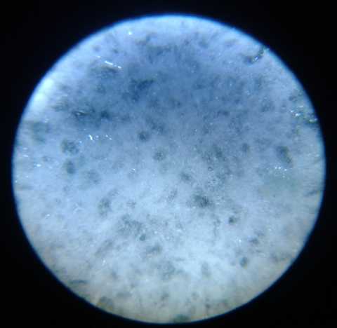
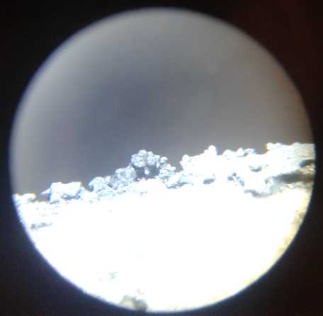 Microscope images of the agared electrode
surface and a 'fuzzy' zinc plated edge. 40x
I had put the cell back together without fixing the bare zinc edges,
and I did a couple of quick load tests around the time I put out the
last TE News. (August 5th, 6th) With each test, performance seemed to
improve. The short circuit tests generally started out 3.5 to under 4
amps, but at first held 1.5 amps for 10 seconds, then 1.75 amps, then
over 2 amps. Driving a 1 ohm load (more like 1.2 with the wiring
losses) it held over 1.00 volts for 2.5 minutes, then the next time
just over 4.5, and the 5 watt resistor got quite warm.
Next I took the cell apart again to paint agar around the
bare edges of lumpy zinc. I discovered that while the jell was still
good, much of one side (having an open edge) had come loose from the
zinc, like wallpaper come loose from a wall. Being unattached would be
acceptable as long as the zinc was totally encapsulated. It would be
pretty much pressed against the electrode anyway. The jell was also
flaking off the stem from the top down. (Ah... It was drying out
there.) It looks like getting a good solid coat of jell is going to be
a rather critical part of the manufacturing.
(7th) I left the electrode overnight to dry. I had cleaned it as best I
could, but I wanted as little potassium hydroxide left on the electrode
as possible, seeing it interferes with the jelling. Here I discovered,
or
probably rediscovered, that if there's one thing a jell can't stand
it's being dried out. It was all loose, dry flakes. I rubbed them off
along with much of the fragile fuzzy plating, and wondered how many
milliamp
hours and how much current drive it would have left. Nevertheless, I
prepared a new batch of jell, a bit 'stiffer' than last time with 50 cc
less water. (What's optimum? I have no idea.)
200 cc distilled water
10 grams agar powder
5 grams zirconium silicate powder (AKA 'zircon', 'ultrox')
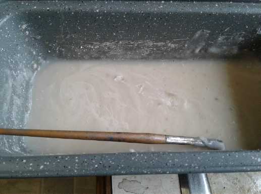 I heated the
water to boiling in a bread pan and sprinkled
the agar powder in. This made a lumpy mixture. Probably better to stir
the powder in and then heat the water. Then I added the zircon. (I
doubtless could better have done that before the heating, too.) I used
a bread pan because it's a good size and shape to dip an entire full
size electrode into to coat it. It's not easy to heat uniformly on a
burner, however.
I dipped in the small one. Then I painted around the edges
with a small brush. After a couple of minutes the electrode had cooled
and I ran my finger around the edges. They all felt like smooth jell
except one top corner. I brushed a bit more onto that to build it up.
I took my somewhat lumpy coated but well encapsulated
'trode and put the cell back together again. Somehow it seemed to need
charging.
On the next load test (#12, @ 10 Ω) the voltages were a
bit lower, but it ran almost the same length of time as the previous 10
Ω test; just a couple of minutes less over an hour. My take is that the
nickel side is what's been limiting the mA-hours, but with some of the
plating (and obviously some of the osmium film, too) rubbed off, the
zinc side has a bit less current capacity and is letting the voltage
down a little. It gave 129 mA-hours instead of 137 because the slightly
lower voltages meant slightly lower currents throughout. Overall the
performance was down just a little. Would it stay there or start
improving again?
On the 10th performance seemed to have dropped a bit more.
I wondered if maybe the nickel was coming apart a bit, or if the two
electrodes weren't pressed together well enough. I managed to insert a
thin strip of metal behind a piece of spacer plastic. It was certainly
tight after that and I hoped I wasn't squashing the agar. But somewhat
to my surprise the currents (short circuit and charging) went up
substantially. It started charging at 300 mA instead of 200, and
delivered over 200 mA after 10 seconds of being shorted. On the 11th, a
10 ohm load test started with slightly higher voltages and current, but
went down faster, to 1.2 volts in 40 minutes instead of closer to an
hour, giving a capacity of only 87 mAH. On the bright side, the zinc
tab hadn't fallen off after almost 20 cycle tests (over double any
other zinc tab electrode I've made), and the charging current still
drops under 20 mA
once the cell is charged and the voltage sits at over 1.8 volts or so
overnight, which indicates no zinc dendrites are trying to short out
the electrodes.
Then next question was, was it the zinc electrode or the
nickel oxide one degrading? It could certainly be the nickel - I was
running it down pretty low. In fact if the zinc was still at 1.24 volts
when the cell was down to 1.2, the nickel must be dropping down to
nothing and maybe even into reverse charge. I needed to replace the
nickel electrode chunks with others as similar as possible and see if
it improved or not.
On the 12th I took the cell apart. One corner of the lower
back side of the agar had been peeled away from the zinc trode, surely
either on insertion or (perhaps more likely) on pulling it out again.
All electrodes are to be inserted together, but perhaps a backing sheet
should slide in with the zinc electrode that's against the end wall of
the cell so that the agar itself isn't sliding along something. Or
perhaps wrap a sheet of cellophane - or just polyethylene - around the
outside of the end electrodes and the bottom when inserting.
The agar I had jelled didn't really liquify when I heated
it up. That may be why it was so lumpy the first time, too. I added
around as much distilled water as jell in the tiny pot, and painted
some on the electrode. I consider that 10 grams of agar in 200 cc of
water made it too thick. I might try about 5 next time (if not less).
So:
Water - 200 cc
Agar - 5 g
Zircon - 5 g
Or I might just heat it up and add another 200 cc of water to the
present batch. (More zircon?)
I remembered the Tokuda et al (Sanyo) Ni-Zn AA cells
patent. I looked up their discharge tests. They ran them from a
charge of 1.95 volts all the way down to .9 volts! Hmm... they didn't
seem to have degrading cycle capacity, at least not for reason of
over-discharge,
over 10 cycles. ???
PAA Jell
They also jelled their zinc electrode. Herein may lie a
buried secret. Some of their cells didn't degrade at all over ten
cycles. If they could make a zinc electrode that wouldn't
degrade, they would be manufacturing them, right? They must have all
degraded over a somewhat longer number of cycles with disappointing
performance, right? Or else we'd already have Sanyo very long lasting
nickel-zinc "AA" cells and probably many other size Ni-Zn batteries.
Right?
But it wouldn't be the first time a company cast away a
superior product in favor of continuing to market and sell their
existing product line, which would be made obsolete by the new product.
Existing companies - at least at the management level - rarely have a
culture of creation or
vision for new technologies. They are generally reactive rather than
proactive. They are usually pushed into advances from behind rather
than leading them. I could easily see the executives just look at its
potential to cut into their ongoing sales of non-rechargeable
batteries, instead of seeing potential for a whole broad new
battery market opening up before them with themselves at the head of
it. Or, it wouldn't be the first time someone 'in charge' was bribed or
threatened by petroleum industry people to shelf a product, and those
for
higher
efficiency, 'free energy' and better batteries have always been the
prime targets. I suspect Sanyo's research team had come up with a
fabulous
advance but Sanyo, notwithstanding apparently having a battery factory
already set up, simply didn't make them, so no one was the wiser. (The
almost illegible patent couldn't have helped spread the word?)
The patent specified polyacrylic acid gel. I found (or was
pointed to) two researchers in the news, a year or two apart but in the
latter part of the current decade, who both claimed to have created a
jelled
electrode that lasted 20,000 cycles without deterioration. At least one
of them mentioned "acrylic" and "jelled" which probably also means
polyacrylic acid gel. Agar seems to work fine, but it's certainly
possible some other jell such as PAA might work better or will be
easier
to work with in production. It certainly bears investigation.
OTOH agar does seem to work well. I ordered a kilogram for
a lower cost from China. The package said "Health Products". (Why they
didn't just write "Agar" I don't know. It seems no one wants to tell
customs agents just what's really in a box.) Customs opened the package
and slit open one of the bags inside. First they were probably looking
for someone trying to buy "prescription" medication, ordered from
abroad because their doctor here wasn't permitted to prescribe it, and
then on opening it and seeing white powder they were suspecting maybe
cocaine.
As long as there are laws against most everything,
senseless or not, the government will suspect its citizens of
lawbreaking. But they didn't challenge the "$5" stated price when as I
recall it was more like 35$. They were probably just disappointed to
have found nothing interesting.
More Research Needed
About at this point, there were too many questions about
what I would actually use for a positive electrode in commercial cells,
and the many options that each might or might not work were muddying
the proposals. Nickel manganates? Nickel oxyhydroxide? Manganese
Dioxide? With graphite or without? In salt or mixed electrolyte, or
must we use concentrated potassium hydroxide? (Samarium oxide to raise
oxygen overvoltage is a given.) Should they be 'jelled' with
sulfonates? something else?, or at least would it be advantageous?
I decided that since I had until late October to submit
the application, I should try to do this research beforehand, which
would make the application much simpler - more clear and direct. The
trouble with salt is that I've never been able to get a positive
electrode to hold its charge in salt electrolyte. It just might devolve
to using KOH or else using manganese dioxide with its lower voltage,
definitely known to hold charge well in salt. Somehow I don't think
that ought to be or will be necessary, but it seems to me I haven't
shown
otherwise in the past. Self discharge has been my greatest bugaboo.
Wait a minute!...
The real reason all my NiMn cells had high self discharge
Then I figured it out at long last! On the 13th I realized
I was probably wrong and that my test for which electrode was
discharging was somehow faulty - that there was a good reason for
gradual self discharge in the negative side in my nickel
manganate-manganese cells. In fact, the zinc sheet current collectors
were fine where they were in contact with the manganese electrode
substance with its overvoltage raising additives, but they degraded
where they weren't: mainly at the terminal tab connection, which would
finally corrode off.
I didn't understand at the time that hydrogen
bubbling off it would affect the zinc. It changes it to brittle zinc
hydride (not mentioned
in battery literature or electrochemistry charts), and being held
at -1.5 volts by the manganese electrode, even tho they weren't the
active substance themselves, the metallic zinc would have been bubbling
hydrogen wherever it wasn't in contact with the hydrogen overvoltage
raising electrode additives, and whether or not the cell was being
charged. (Well duh, of course it would!) There was the gradual self
discharge, slow but relentless, not
from the electrode itself but from the zinc terminal tab. And even when
I switched from zinc to 'flexible graphite' current collectors, the
graphite
didn't decay but most probably it also bubbled hydrogen at such a high
voltage.
SO! That was probably the reason my extra high voltage
cells always had 'overnight' self discharge instead of holding charge
properly. To make such a high voltage electrode hold its charge, the
hydrogen overvoltage ingredients - or an insulating paint - would have
to coat the entire exposed current collector inside the cell. Now that
I think I understand that, I could probably make the 2.4 volt cells.
Well,
some other time!
Painting Parts of Electrodes to Prevent Gas Generation
Overnight it dawned on me that that idea of painting the
terminal tab would also be very good for a plain zinc electrode. The
hydrogen overvoltage substance (zirconium silicate) is in the agar and
it can't extend up the tab right to the outer case. Paint can. The
terminal strip should be painted or epoxied, and the whole back side of
single sided electrodes could also be painted, although the agar with
the zircon should do the job.
This also reminds that likewise the oxygen overvoltage
substance (samarium oxide/hydroxide) is in the powder mix, but not in
the carbon fibers running up to the top to form the "tab". It might be
necessary or at least advantageous to paint these, too, or perhaps
better for those to epoxy them into a solid piece.
Making Nickel-Manganates '+' Electrode in a plastic shell
Zinc electrodes will be easier to work with - and if the
nickel manganates side is indeed working at the high "+" voltage it
seemed to have in those earlier cells, they may still be around 2 volts
in salt - as high as lead-acid and just six cells for a 12 volt battery.
I may experiment with nickel manganates-manganese 2-1/2
volt cells again (just 5 cells for 12 volts), but the coated zinc
electrodes are working well, and at this point I'm going with that.
So the next experiment would be a nickel manganates "+"
electrode... and it would probably work.
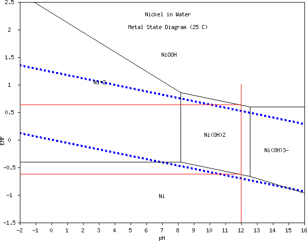
![[graf]](MnPourbaix2.png) I
may have found a potential reason voltages seemed higher than I
had expected in my nickel manganates-manganese cells too: the voltage
of MnO4- would be around +.75 volts at pH 12. It was KMnO4 I put into
the cells to react and form the manganates. Perhaps that voltage also
applies to the manganates, rather than the nickel oxyhydroxide voltage
(~+.65) that I had expected. Add +.75 to -1.5 for metallic manganese
and you have about 2.25 volts. Even so they charged even higher, to 2.6
or so (dropping quickly to 2.4 volts under load), but most cells charge
somewhat higher than theoretical.
I
may have found a potential reason voltages seemed higher than I
had expected in my nickel manganates-manganese cells too: the voltage
of MnO4- would be around +.75 volts at pH 12. It was KMnO4 I put into
the cells to react and form the manganates. Perhaps that voltage also
applies to the manganates, rather than the nickel oxyhydroxide voltage
(~+.65) that I had expected. Add +.75 to -1.5 for metallic manganese
and you have about 2.25 volts. Even so they charged even higher, to 2.6
or so (dropping quickly to 2.4 volts under load), but most cells charge
somewhat higher than theoretical.
But there's also the CRC Book graph at
pH 1 and pH 14:
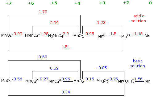 If perhaps in
nickel manganates the form MnO4--- might for some reason
prevail, that would give +.15v + +.96v = +1.11V. That plus the roughly
-1.4v provided by the Mn negative would better explain cells that
charged up to 2.6 and even 2.7 volts. Was that the case?
 The experiment, now with a zinc negative, is the thing!
[Ahead of the narrative: The experiment showed that, for all this
speculation, the voltage was initially about the same as nickel
oxyhydroxide,
+.65 volts at pH 12. Then with some short circuiting and recharging it
seemed to get lower... perhaps to the voltage of MnO2+Zn, under 1.5.
But that's okay if it moves 2 or 3 electrons instead of 1. The
amp-hours would go way up in the same size cell.]
(13th) On the old RepRap Mendel 3D
printer I had always got the bed up to at least 95°C, preferably
100, before I tried printing ABS. The new printer only heated the bed
to 80° for ABS. I didn't and don't consider that anything like hot
enough. While the PLA shells had printed very nicely in the new printer
if the extruder temperature was increased to 200°C (a miracle!),
when I tried in ABS the bottom printed fine but the ends started
lifting on only the second row and the pieces broke away from the
glass. So I had to give up and go with a PLA shell.
The only electrode compactor I could find was the one made
as an edge-fed compactor. Either I've let the others slip away somehow
after I moved here (probably), or I wasn't looking in the right places.
The edge one will do.
I used the powders already mixed in July:
Monel Powder - 16 g
Ni(OH)2 - 17 g
KMnO4 - 40 g
Conductive Carbon Black Powder - 5 g
Sm2O3 - 5 g
I wetted these with a few drops of "Lemon Fresh Sunlight" dishsoap. The
ingredients in that, especially the sulfonates, are there to form a
jell. (Hmm... Sanyo had a "kneader" to help mix things. I must go on
line and see just what that is and look for one. Hmm... does it replace
the "compactor"?)
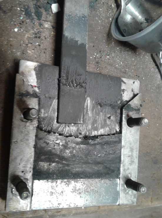 I
used a flat rod to tamp the powder/soap mix with. It
seemed to get very solid as I tamped. I added just a bit at a time and
tamped some more. When I took the front off the compactor, it looked
just about how I wanted it. I trimmed off a couple of bulging corners.
I started to slide it off the back and it immediately cracked into 3.
Hmm... not really very solid after all. Maybe I should have used the
hydraulic press after all?
I
used a flat rod to tamp the powder/soap mix with. It
seemed to get very solid as I tamped. I added just a bit at a time and
tamped some more. When I took the front off the compactor, it looked
just about how I wanted it. I trimmed off a couple of bulging corners.
I started to slide it off the back and it immediately cracked into 3.
Hmm... not really very solid after all. Maybe I should have used the
hydraulic press after all?
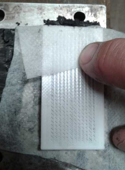 But if the mountain
wouldn't move, maybe put
the cap over the mountain? That worked quite well. The piece was
actually a bit long, but the edge of the shell just cut it off. So I
had a pretty much intact (if extremely fragile) briquette that filled
the shell, with an unbroken section of PP cloth in front of it to make
sure none could come out to short against the zinc.
(I knew I was forgetting something. I forgot to paint the
inner surface of the electrode with calcium oxide/hydroxide. It's a
useful layer.)
I put the carbon fiber 'cloth' over that and wrapped it
all up in the PP cloth.
Methylene chloride won't 'glue' PLA, but on youtube I
found out that cyanoacrylate (Krazy glue) would. So I broke open a tube
of that and put it around the edges. I didn't trust it to stay together
while setting, so I put the 'trode in the hydraulic press and squeezed
it pretty lightly (but heavier than just setting some metal weight on
it) and left it a while to set. (How long does that take, anyway? It
was trying to stick my skin on pretty fast.) Later I removed it. The
whole thing seemed pretty solid.
I had a great picture of the open face with the cloth but
without the current collector. It was the last one I had been looking
at; where on Earth did it go? I suspect my cell phone of turning itself
on in my pocket and spuriously deleting it. When I'm outside working I
repeatedly pull it out and find it turned on with all kinds of stuff
running. There's been a message on it for weeks that I need to take
"account action" at "Google Play Store", where (as far as I remember) I
have never been. I suppose it's been trying to buy things. (surely not
some scam?) Other peoples' phones just redial the last called number
from their pocket.
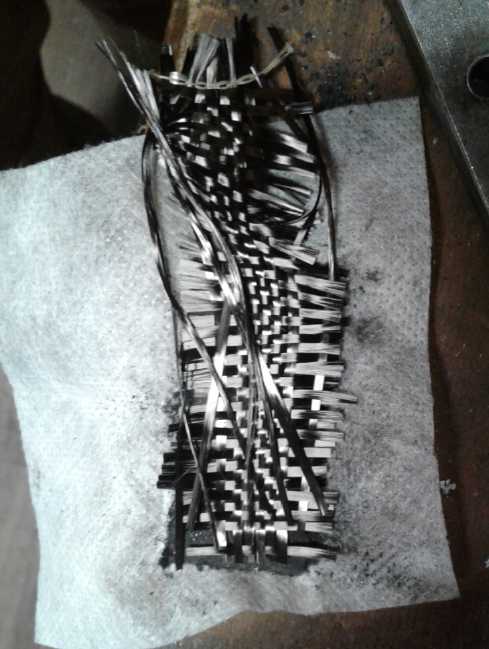
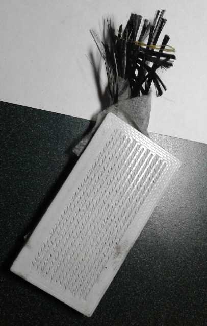 I wasn't at
all fussy about the terminal connection.
Something had to be done about that. It came to me that I could make a
hollow rectangular plastic tube, a terminal extension to the shell that
would contain the strands of graphite fiber and guide them up through a
hole in the lid. (In the next shell I ended up making a shallow trough
for the strands.)
Then perhaps at the exposed top, it could have one face
open, and a graphite block would be inserted in front of the mess of
fibers. The external connections would be made to this. This would
imply that each '+' electrode would have its own external pillar on the
top. They would have to be joined with a bar or piece of wire. (The
graphite strands might also have to be coated with Sm2O3 - or
insulating paint - to prevent oxygen generation. Epoxied maybe? That
will have to be seen.)
(For the zinc side I conceive that all the tabs will bend
over and come out one "slit" hole. Either that or they will each come
out their own slit and be bent over above the case to join externally
on top.)
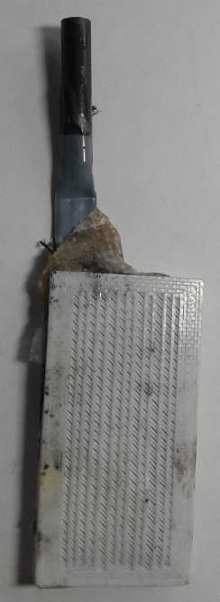 (14th) For the present I gathered all the
loose strands of graphite
into a short piece of plastic drinking straw. I found a piece of
graphite rod and sanded it down so it fit into the straw. Then I mixed
some epoxy and painted it in to fill the straw before I jammed the
graphite bit in. I put a weight on it to flatten the straw where it
would come out the slit in the lid of the cell. I hope the connection
is good.
I tried to warm up my kitchen oven to set the epoxy faster
than free air temperature, and found my new oven wouldn't warm. It
either wanted to be off or baking hot. The digital control would only
go down to 170°F (75°C)! 65°C is the tops for curing epoxy.
I'd have preferred 50°. But it was even worse than that. While the
oven measures the temperature in 5°F steps and is perfectly capable
of displaying it to the operator, it will only show the actual
temperature in two conditions:
1) While the oven is warming up and
2) The oven timer is off
So to set the timer for just a few minutes so it won't get
up to the (minimum) setting of 170°, means it simply will not show
the temperature. No way to see it! There's cause for alarm bells
already. So after a few minutes I canceled the heating entirely. When I
then selected "cook" and turned the oven on again (not that I wanted it
on), it showed the temperature. It was already 230°F! S**T!
I grabbed the electrode with the metal weight pieces and
pulled it out. It had heated so fast that the metal weights weren't hot
enough yet to burn my hands, but the plastic had become quite soft and
was bulging out. I set the weights on top and squeezed it flat again.
(Now it bulged a bit at the sides.)
Now, one might think "But
that's not what kitchen ovens are
intended for." But I might want a just-warm oven for other things. For
rising bread dough for example. That is a common oven use, and if it
wasn't for having a bread machine I would
discovered the problem long ago. Or what about for just keeping food
warm
for a while? My disgust with the shoddy programming, so poorly thought
out and so typical of so many electronically controlled products,
remains. (And: why have an ultra-fast magnetic induction hotplate
burner
that warms water for yeast in 40 seconds and boils it in 90 seconds...
and is only programmable, and only displays, to the nearest minute -
did you want 0, 1 or
2? I did far better than that with my own stove burner control in 1986.
And: why make a delicate
weigh scale so that it keeps zeroing itself as the user slowly adds
epoxy trying to
get an accurate and exact weight, so that he has no idea how much he's
actually poured in? You can't pour the gooey stuff back and try
again! The list goes on... I know we all have to forgive others in
order to have the capacity to forgive ourselves and move on. I have a
peculiar
resentment with "whoever" does this sort of thing,
being such a good programmer myself. And I don't even know the person!
Or maybe it's with management for
rushing a new product out the door without allowing the programmer
enough time to work out the finer points? Whenever I've worked on any
such
product I would try to anticipate all the uses to which
it might be put, and make the software that runs it as versatile and as
user friendly as
possible. Allowing an electronically controlled oven to be warmed up
and stay warm seems like a no-brainer to me.)
Sorry for the diatribe. (Perhaps I should have grabbed my all-time
favorite kitchen stove with its digital display but oven temperature dial
when I moved, and left some other one in its place.)
Back to the plot... at least the oven episode showed me
that if I have assembled a warped electrode shell, or wish to press it
together better, I could heat it to soften the plastic. But the next
electrode showed the printed plastic breaks easily.
While I waited for the epoxy to set (very slowly at room
temperature), I started in on designing an improved electrode shell.
One of the last ones hadn't fit well - it took a bit of a snap to get
it together (sometimes it would stay), and that gave me the idea. If I
could make them so they would snap together properly, they shouldn't
need to be glued. That would mean I could print them from PLA and avoid
the problems I was having with ABS. And besides, once all the bits had
been delicately placed within, snapping it together at once would give
much less chance for things to shift around, and one wouldn't have to
hold it until the glue set. And it would be done - much better for
production.
So I started trying to minutely adjust dimensions (more
trying to adjust for the vagaries of the 3D printer(s) and 'Skienforge'
'slicer' program than for theoretical dimensions) to make a slot in the
base and a lip in the top that would snap into it when they were
pressed together. (If the first shell had snapped together not only
would it not have needed krazy glue, but I could have pried it open
again
and painted in the forgotten Ca(OH)2 layer by the current collector.)
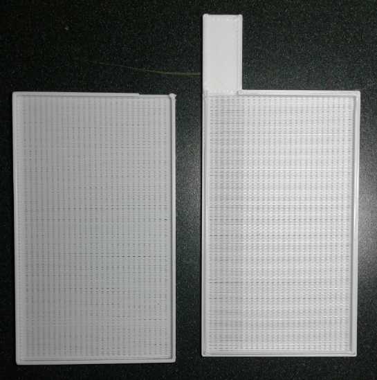 Later I
returned to it and decided to do the "full size"
electrode shell. All the minute adjustments would have to be done over
for it. I printed one. It looked pretty good. But I made the grille
bars
on 2.2 mm centers instead of 2.0, and without any change in the 1 mm
bar width, it printed them as two beads instead of one. Then instead of
printing the second layer as diagonals, it printed them square across
in the other direction. Those things were both notable improvements...
but who
would have guessed they would happen? Or... Aha! It was because I made
them
open at the top (for bubbles to escape). Just where the terminal tab
was on one side so the tops weren't open, it did them the old way. I'll
have to fix that. And I
want to make them still wider apart since the double trace actually
narrowed the bubble slots instead of widening them. And it didn't
"snap" together - it was a sloppy fit. And somehow I'd made it too
short.
It was 1 AM PDT (23:12 by the sun) and that was about it
for that day. But I was on the case. It looked like it would work great
and they ('perfected' ones) could be used for production!
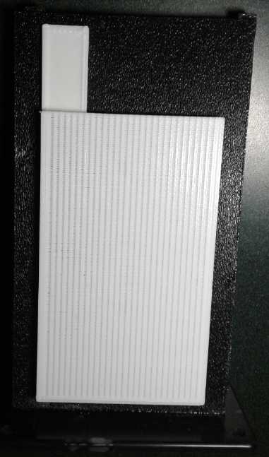 Hmm, somehow an inch short for the 'full size'
battery case
Cell Assembly and Tests
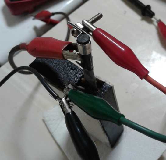 On the 15th I mixed some potassium chloride solution, 35 g
of KCl in 100 cc/ml/g of H2O. I put a new piece of plastic in as a
slightly thinner case filler than before since the plastic shell
electrode was fatter than the other ones. It took a little under 20cc
to fill the test cell. The solution turned purple from the potassium
permanganate. But only a few grams per 100 cc will dissolve into water.
The rest should remain solid - and jelling it should help make it
permanent, too. (Perhaps in times past this purple herring distracted
me from realizing it was my negative electrode causing the self
discharge.)
I put it on charge and was disappointed by the small
currents. Short circuit wasn't much either. Well, I had only compacted
the electrode by tamping down the powder... perhaps it wasn't well
enough compacted to have good internal contact? But that wasn't it.
There was a poor connection at the zinc electrode - again. I should
have put a bolt through that zinc tab sometime!
After that it started taking a charge and shaping up. I
had to go over 2 volts to get much charging current.
1.9 V: 10 mA
2.0 V: <20 mA
2.1 V: <30 mA
Soon it was putting out some short circuit current, with a
spike to only .55 A when first connected and dropping to 200mA
after 10 seconds. (.50 & .290 A after leaving it a while longer.)
And when the charge was removed, the voltage kept dropping gradually.
Now it really was in a performance range that might well be a result of
poor conductivity in the "+"trode . But maybe it would improve. The
nickel hydroxide and the potassium permanganate were supposed to get
together and form nickel manganates.
I decided they could take their time doing that and left
it at 1.9 volts charge. In fact, it occurred to me that I should keep
the voltage below where more permanganate would form and 1.9 was tops.
The electrode was made with KMnO4 in order to provide an oxidizer
hoping it would form nickel manganates, but it wasn't intended that the
manganese would stay in slightly soluble permanganate form perpetually.
I went and washed some 50
cc beakers that had been sitting
around a while now. I didn't remember what was in them, but there
wasn't much of anything - 5 cc of liquid or a residue on the bottom.
One I couldn't seem to clean. Oh ya... the barium carbonate. from the
nafion experiment. The barium is said to bond with glass. I think it
worked! Perhaps I could have fused two pieces of glass together with it!
A couple of hours later it was charging at just 5 mA. The
short circuit currents and very gradual recovery after shorting hadn't
improved. I started thinking maybe I should have used the whole 20
grams of conductive carbon black after all instead of just 5 grams.
Maybe I had thought out this formula better in February 2014 (TE News
#73) than I thought I had. Plus, I had made the 'briquette' thicker
than I wanted, so there was more material in it to charge. The edge
compactor is made to a specific thickness, in this case about 3mm. (I
could make thinner side and bottom walls and thinner inserts to tamp or
press the powder down. It's all extra work.
After over 3 hours, when disconnected from charge it
dropped to 1.826 V after 10 minutes and was dropping by less than 2
mV/minute. But with the poor conductivity one anticipates that it will
continue to fall for a long time: not "self discharge" but rather as
poorly connected areas of the electrode gradually take up and dilute
the existing charge. How bad is the conductivity? It puts out .5 amps
instant when shorted where a good nickel oxide bits one was doing over
3 amps. That's only 1/6th as much current. One might hope they would be
similar.
So what was next... make another new electrode after
adding more conductive carbon black, and squashing the powder more
strongly in the hydraulic press? I would leave this one on charge
overnight, but now I wasn't expecting much improvement. There was one
bright spot: If it wasn't self-discharging, it worked in principle. It
would take a lot more of this painfully slow charging and then a few
hours off charge to see if the voltage finally did hold somewhere to be
really sure.
I note that in spite of speculations the voltage seemed
very similar to the nickel-zinc alkaline version.
I decided to do a discharge and recharge to see if
anything useful would happen. I ran a 60 ohm load. It ran for 35
minutes and I stopped it at 1.3 volts, having transported a whopping 11
mA-H of electrons. Obviously the discharge was limited by the plus
side, since it was the same zinc electrode that had delivered far more
in previous tests.
Of perhaps more interest was the recovery. In an hour and
20 minutes but mostly in the first few minutes, it got back up to 1.743
volts. In the last 20 minutes it only went from 1.739 to 1.743. The
fact of it slowing and slowing without reversing and starting down
again indicated a very low level of self discharge. For all the
improvements the positive electrode needed, chemically both electrodes
and the salt electrolyte worked. It was a battery.
This was cycle test #20 for the same Os filmed, agared
zinc electrode (albeit with some re-agaring 3 or 4 times to replace
that which had got scraped off in removals and re-installations), so
confidence in it was increasing. What remained to be verified was that
the plus side would likewise hold up over longer cycling. There was
little reason to suppose that it wouldn't.
My hopes that performance would improve - or even just
stay the same - were dashed on the 16th when a second cycle test gave
less current and lower amp hours. I wished I had painted the calcium
hydroxide layer between the electrode substance and the current
collector. What to try now? How about potassium oxalate instead of
potassium chloride? Things are less soluble in oxalate.
I took the electrodes out and briefly rinsed them. I rinsed the cell
and plastic spacers. For some reason I finally remembered to punch a
hole in the zinc tab and put a bolt in. The connections should become
more reliable. I filled the cell using 6 cc of KC2O4 (the electrodes
already being wet).
The currents seemed just a little higher. After 10 seconds
shorted or even 15, it still put out about 300mA. It occurred to me
that neither salt was amazingly soluble. 112 grams of KOH will dissolve
into 100 grams of water. For KCl it's about 34 and KC2O4 is 36... just
a little higher. Could the current capacity be regulated by the
concentration of salt in the electrolyte, rather than the type?
But water will hold different things. Perhaps if one
dissolved in KCl AND KC2O4 it would be closer to 65 or 70
grams, and might that increase the current capacity?
It now contained oxalate. What would happen if I added a
couple of grams of KCl to the 6 cc/grams of liquid? It didn't seem to
make much difference at first. OTOH it might take a while to dissolve
well, and the cell could probably stand some charging.
Waiting a while didn't help. What did help somewhat was
scraping the alligator clip against the graphite rod "+" terminal. It
had been a poor connection. That raised the short circuit current from
.4 to .6 amps, holding over .3 amps longer, but it still didn't give
much in the way of amp-hours in a load test.
In all this, with two different types of salts, there
seemed to be no appreciable self discharge. That was certainly
heartening. I did find there was some overnight, which I attributed to
the lid not fitting so air could get in.
I made a clamp to screw onto the graphite rod to ensure a
good connection. To my surprise it made a big difference. Short circuit
current went up to .77 amps momentary and held at over 1/2 an amp for
10 seconds. I started to wonder whether there might be any other poor
connections besides in the electrode substance itself. Electrode
material to graphite fiber current collector? Graphite fiber strands to
graphite rod? (Notwithstanding that they were pressed into the straw
and epoxied together. Epoxy isn't a conductor.) Did the jell reduce ion
flow? Aligator clips? (Always suspect!)
I ran another 60 ohm discharge test. It was doing so
poorly I didn't bother to record it. It was down to my arbitrary cutoff
of 1.3 volts in just 6 minutes. But the voltage drop was slowing at the
end and I decided to continue. It took 30 minutes to run down to 1.083
volts. So there was some current and storage, however little.
(17th) Well, what about more of a mix? I added a bit of calcium
hydroxide. It didn't seem to do much. I added 1 gram of potassium
hydroxide. With 6 of water, that should be about s.g. 1.17, so:
H2O 100
KCl 34
KC2O4 35
KOH 17
Ca(OH)2 2
Evidently 100 cc of this water should weigh 195 grams. Strong stuff! It
seemed to perk it up a little, but not very much. pH tested out at
about 13. (Hmm... other people use pH meters instead of test
strips. Why have I never looked for such a thing on line?)
I tried a 100 ohm load instead of 60. It seemed a bit
silly, but the voltages stayed much higher for longer. In fact, it was
putting out almost as much current as with 60 ohms because of the
higher voltages. The high internal resistance was preventing it from
performing except with the lightest of loads.
New Electrode: New Shell, More Carbon Black, Diesel Kleen,
I decided I needed to make a new electrode: add more
graphite, compact it more strongly and put the calcium layer where it
was intended. First I needed to make a new shell. Rats, why had I been
designing an improved "production-size" shell instead of the test size?
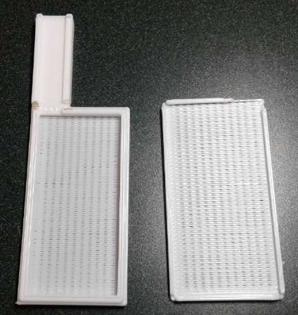 On the night
of the 17th I did the shell, and ended up
after several tries with a 'porous' shell that snapped together,
perhaps a bit loosely. (Better than the previous ones that that
wouldn't quite go) It had a 3-sided plastic terminal tab to bring the
long strands of carbon fiber up to a terminal. I figured the strands
could protrude up from the current collector through the shallow
"ditch", some heat glue or epoxy could seal it at the top of the case
to keep electrolyte away from the metal above, and I would bolt a piece
of metal to the plastic tab with the strands pinched between. or
better, two pieces of metal (thin and thick) with the strands pinched
between them.
I was starting to wonder whether the "porous" bit could
even be done with an injection mold. That process tends to make solid
pieces. A mold would have to have all the minute points for all the
minute perforations. For 350$ each, perhaps it would be better just to
get as many 3D printers as needed to keep up with production demand.
(Almost surely that's the best route for small scale production.) Or
there are higher priced "production" 3D printers that will churn out
the parts and eject them into a pile. Those could run all night.
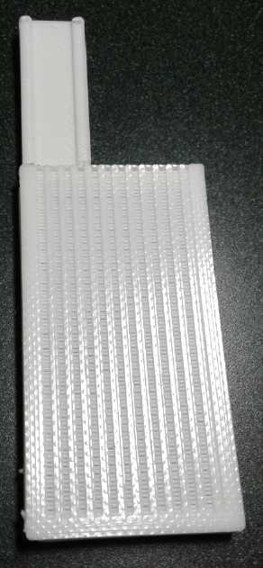
I added 10 more grams of conductive carbon black to the
"+"trode mix, making 15 g of it, not counting the few taken for the
first electrode. It's so light and fluffy it seemed like a ridiculous
amount. But there's a point of concentration below which it's not very
conductive and above which it is. That point also depends on how well
the powder is compacted. I want to compact it better, but I also want
the next electrode to work.
I spilled a little of the featherweight stuff, which
clumps up on the spoon. When I tried to wipe it off I remembered about
graphite... the more you wipe, that darker it gets and the broader the
blackened area. It's not that you aren't getting some up in your cloth
or tissue, but what's been swept up gets spread around with every
subsequent wipe - I suppose until it's down a single atom thickness of
graphene.
But this reminded me that I had the one thing that will
dissolve such graphite powders: "Diesel Kleen". That was about the only
thing that would take the black away. And that reminded me that if you
used it in an electrode it would dissolve the graphite in it, and as
the Diesel Kleen [eventually] evaporated, the graphite would reform
into minute conductive paths, "lamilae", which significantly increases
the conductivity of the electrode. (Do I recall that it improved the
conductivity by around 40% some years back?) I wondered if that might
improve my first electrode. But it might not be very compatible with
the dishsoap jell. Still, if I was otherwise discarding the electrode
anyway, maybe it was worth a try, just to see what would happen? And
what would it do to the carbon fiber current collector, and to the
connections to it? Now there was a really interesting question.
That was definitely worth some experimentation as it just might result
in much higher current capacities.
I decided to do the new electrode without the Diesel
Kleen. Then I could do one with it later and compare them. I used the
press this time to compact the mix. I wanted to do 5 tons, but the
pressing pieces bent at 2 or 3 or 4, and if not, pressed in down to the
top of the edge compactor and could go in no further. I remembered the
layer of calcium oxide between the active briquette chunks (it broke up
in the press) and the carbon fiber current collector. It was too fat
and the "click together" edges of the shell wouldn't stay closed. So I
put in some Krazy glue and put it in the press under a bit of pressure
again. The carbon fiber cloth really falls apart especially in small
pieces. The strands don't stick to each other at all. I think next time
I'll sew all around the edges before I cut them (if my grandmother's
sewing machine still works - it didn't seem to stitch properly last
time I tried to use it a couple of years ago, but I couldn't see why
not.) I'd try ironing on polyamide onto the back, but I already know
that has nitrates that would cause self discharge. (Hmm, what about
polyethylene or polypropylene, if it's a single sided electrode? Have a
sheet of cellophane between the iron and the plastic to keep it from
melting to the iron.)
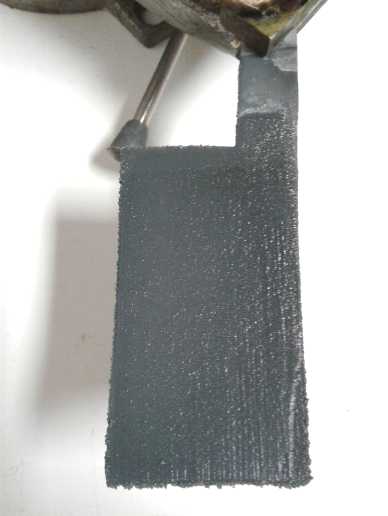 Then I decided
to make a new zinc electrode as well. The
other one was still working fine, but it didn't have much fuzzy
plating. A
thicker one should have both more amps and more capacity. (Of course,
it was clearly the dry cell nickel oxides bits electrode that was
limiting the capacity, and the poorly compacted nickel manganates one
didn't seem to work well at all.) After plating it weighed 7.8 grams.
Assuming it was about 4.4 before, that's 3.4 grams of fuzzy plating
adding a theoretical 2.8 amp-hours, 1.4 to each side.
The fuzzy surface soaked up a discernible amount of the
osmium doped acetal ester, unlike a smooth surface that only takes a
few drops. I painted both sides. Then I did an ugly job of agaring it -
the brush strokes showed -
but I think I got it covered. (I ordered a lab heater/magnetic stirrer
last month. I wish it would get here. Trying to do liquify the agar in
the
microwave or on a stove burner is the pits.)
I put the new cell together
and used simple KOH. But in
spite of triple the conductive carbon black and stronger compaction,
the
cell didn't seem to work much differently than the last one. One
advantage I have now over previous years is that this time there was
only one
part that was untried, and that was still the "+" electrode. There was
no reason to think that the zinc "-" would perform notably differently
from
the last very successful ones, or that the cell wouldn't work with KOH.
It had worked well with the commercial dry cell NiOOH "+" electrode
bits.
It was clear where to look: the problem had to be in the nickel
manganates electrode as made. In previous years I hadn't been 100% sure
I was looking at the part that was causing the problem. Then I
remembered a technique I hadn't
applied: drying and then briefly torching the briquette to tend to fuse
things together a la sintering.
Once again I had the 'trode in a glued together shell that
I couldn't disassemble. At first I decided to make a third "new
formula" "+" electrode and try that. (Could I get the "click" working
better too?) Then I decided to soak the first 'trode in Diesel Kleen,
wait for it to evaporate (two days - and the smell wasn't entirely
gone) and see how it worked.
Tentative Procedure for Making Positive Electrode (Aug 22nd 2019)
Well, this is more involved than the zinc electrode, for
sure. (Unless perhaps the steps for making osmium doped acetal ester
are counted for that one.) Bear in mind that these are quite
preliminary and various better methods may be found.
1. Print 'porous' plastic shell on 3D printer. (I don't have my shells
anything like 'perfected' yet. Open SCAD designs will be released after
that.)
2. Mix electrode briquette powders:
16 g Monel
17 g Ni(OH)2
40 g KMnO4
10(?) g Conductive Carbon Black
5 g Sm2O3 (Alternatives: other rare earth oxides or
hydroxides, eg, Nd2O3.)
3. Wet with a few drops of Diesel Kleen
3-1/2. New: Use a "kneader" to thoroughly mix and combine the
ingredients.
4. Compact powders into a 'briquette' electrode (See new section on
"kneader reactor", below.)
[Yet to be tried: 4-1/2. Singe the briquette or briquette material with
a torch.]
5. Cut polypropylene cloth (PP) to line the shell. (Wraps around the
briquette(s) and carbon fiber current collector, no gaps.)
6. Cut carbon (graphite) fiber current collector to fit shell. (I think
it might be a good idea to stitch it together with a sewing machine,
criss cross everywhere, because it falls apart by itself.)
7. Set the PP in the shell
8. Set electrode briquette on the PP
9. Paint inner (now top) surface of briquette with a bit of CaO /
Ca(OH)2
10. Set the carbon fiber on the electrode. Route the long strands up
the terminal channel. (It may be very desirable here to wet it with
Diesel Kleen for better conduction to the briquette.)
(11.) If it is a two faced electrode, paint another layer of CaO on th
carbon fiber sheet (or on the second briquette.)
(12.) Put the second briquette onto the carbon fiber
13. Wrap the sides of the PP cloth around to cover everything inside
the shell
14. Snap the shell closed
15. Wait for the Diesel Kleen to evaporate. This will take a couple of
days(?) (it should have dissolved and hence redistributed the graphite
and made the electrode far more conductive.)
16. Bolt in the tops of the fiber strands to make the battery "+"
terminal
17. Epoxy the strands into the channel, with care to get it even at the
level of the battery top so it can be easily sealed. (If electrolyte
gets up to the metal, it will corrode.)
(22nd) I put the cell together and poured back some old electrolyte. It
didn't seem to perform very well, with low charging currents. The
voltage only rose slowly with the charge instead of just jumping up to
1.8xx without complaint. That was unusual. I found the terminal clamp
on top of the graphite rod had started to corrode. I twisted it around
and the voltage jumped up.
I changed the electrolyte to new 20% KOH. It was an
improvement. Then I added 10% KCl to that, making it 30% total
'thickness'. pH was 13. I think that
helped a bit too. The electrolyte mixture definitely could use some
careful experimentation. A load test was only marginally better than
before.
There must be some trick to making a good "+" electrode
that I wasn't catching on to. Maybe I should try some more conventional
mix - especially, MnO2 instead of KMnO4. (and maybe the 'kneading'
would help?)
That was the main difference between my mix and anybody
else's. Perhaps it was a stupid idea that using it would help form
nickel manganates? The potassium might want to hang onto it. Okay,
others have used MnO2. If one could discharge the permanganate it
should become MnO2, and the potassium would have to exit and strengthen
the KOH solution. Of course, that might not make the electrode work
well because when a "K" and two "O"s are subtracted from the "Mn" and
"O2", that should leave a lot of voids in the formerly compacted
electrode.
But wait... wasn't that part of the plan in the first
place? That nickel manganates would form as part of the discharge and
charge cycling process? So: run the cell way down and get the Mn
valence down into lower oxide forms. If one went low enough, the nickel
might even become metallic form - a good reason not to have strong KOH,
since the nickel wouldn't recharge in pH 14 alkali - once metallic it
would just stay that way. Then recharge and see what would happen. The
manganese component wouldn't discharge beyond Mn(OH)2. Maybe the Ni had
to get down to metallic form to want to then grab onto a manganate or
two instead of (OH)- ions during the recharge?
HOH could come and go, K+ ions could come and go. Could it
be that the main difference between using MnO2 and KMnO4 was those
interstitial spaces left by the discharge of the manganese? And would
those spaces be beneficial or deleterious? Probably the best way to
find out would be to try both.
I put a 20 ohm load on it and in 20 minutes it was down to
2/3 of a volt and putting out 30 mA. Was that enough, or should I keep
going? Soon I put it on charge again. After 15 minutes charge current
was pretty low. The next discharge looked worse than than the first,
the voltages dropping sooner. (But then it probably wasn't as well
charged.)
Then I decided that was just pussyfooting around. I
shorted out the cell and left it there. It was really almost 2 ohms
through the current meter on its 200mA range, and so the current
started at just 150 mA, with a voltage of ~275 mV showing on the cell,
and dropped from there. In 20 minutes it was down to 42mA and .077V,
but the drop had become very slow. By 50 minutes it was 32mA, .058V.
There were lots of tiny bubble around both electrodes - probably oxygen
coming off the positive. Presuming there was less positive reactant
than zinc, one could completely discharge the positive electrode
(apparently quite gradually) to "reset" everything in it and get that
desired nickel manganates form with its more conductive spinel crystal
structure.
I moved the meter to the "10 amp" range because it had
less internal resistance. Now the voltage was just .007, but the
current, which had dropped into the 20mA area, went back up to ".03".
After 2 hours it was still .03 A. The surface of the water was a froth
of tiny bubbles. I suppose if I took it off and charged it after 3
hours of that, it would still only have .09 AH of charge that would
convert to manganates. That meant to really make it work one would have
to leave it on overnight, if not for days. I had one more day before
leaving on holidays, and I had to get ready to go. I would leave it a
few more hours and give it a try in the evening. But soon I had the
thought that if even some of the material became more conductive, the
process might get faster. I removed the short and the voltage wage up
to .7 in a minute or two. I put the charge back on. It started at 210mA
and dropped as the voltage went up over 1.8 (with the charger being
about 1.92V). After a while it was 50 mA, then below 30. Apparently it
would take as long to recharge as it was taking to discharge when
shorted. Perhaps I should give it an hour or two.
Kneader Reactor
In looking at the Sanyo patent again I noted that the
gamma nickel oxyhydroxide was first "mixed in a kneader":
"Subsequently, 90 g of the
nickel oxyhydroxide powder obtained, 5 g of
graphite powder and 5 g of a 40 mass% potassium hydroxide aqueous
solution were mixed in a kneader for 30 minutes to obtain a positive
active material."
No doubt that's all pretty standard, but the "kneader"
idea was unfamiliar to me apart from bread dough. I found out they're
usually called "kneader
reactors" or "kneading reactors", and sometimes "kneader-extruders",
and
that they are usually very large machines with shafts and blunt
'blades'. They "react" high viscosity or even dry substances by
kneading them together. 30 minutes is certainly more than just a quick
'mix' of the substances. Move over, mortar and pestle!
I can't imagine what one would pay for one of those huge
machines - surely too much just to do limited production. But I'm sure
it should be
possible to create some small kneading machine to do the basic job,
given all the ingredients essentially pre-stirred by hand and poured
into a vat on top of the machine.
The kneading, however useful, didn't seem to replace
compaction. But I speculate that it probably substantially reduces the
compaction pressure required to get a good electrode texture:
"This active material was then
compressed in molds into a hollow
cylindrical form to prepare a positive electrode having an outer
diameter of 13.3 mm, an inner diameter of 9.0 mm and a height of 13.7
mm." [3 like that end to end makes an "AA" battery outer
electrode.]
FWIW: Cupro-Nickel as Alkaline "+" Current Collector
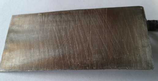 I
note that it is has been said that any metal but nickel
will oxidize and corrode away in the 'positrode' of an alkaline
battery. Only nickel "passivates" at pH 14 (by forming an attached one
molecule thick oxide layer "skin", similarly to aluminum or titanium at
pH 7). Nothing I've read anywhere indicates anything else (besides
graphite/carbon) will work. But after all these weeks in the battery in
KOH solution, my cupro-nickel (70:30) current collector piece looked
almost like new including under a microscope, except that some patches
(those not contacting the electrode chunks) looked slightly coppery -
or perhaps it was a very slight tarnish - and others (mainly in good
contact
with the electrode bits, but also the whole back side) more the
original silvery. (There was a faint horizontal line across the back,
perhaps where a piece of plastic had once had its edge, or a half full
electrolyte level.) (Monel, which has a higher nickel content, probably
wouldn't tarnish or discolor at all.)
I went out to the shop to check
it against the original color. A large piece there had some of the same
coppery color in a strip along one edge, as well as a couple of patches
of green copper or nickel oxide where it had been resting against a
2"x4" post. Most of the sheet was silvery, but duller than the piece
from the cell. So it actually looked worse.
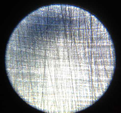 Clean face of used cupro-nickel current
collector at 40 x.
Quite probably the 30% nickel content would actually mean
an increase in the amount of nickel over a piece of nickel
electroplated other metal, but it seems pretty impervious to corrosion
in pH 14 electrolyte, whereas once nickel electroplating has been
breached, the whole item will corrode away. I have however no plans for
using it or for long term tests. Salt electrolyte will eat away any
metal, which is why graphite rods are used instead in standard dry
cells.
Since I'm using graphite fiber current collectors and
conductive carbon black for conductivity enhancement, my
nickel-manganate / zinc cells will in fact use less nickel than any
other rechargeable alkaline cells. How the carbon fiber terminal tab is
to be made I'm less sure of. Perhaps wrap protruding fibers into some
sort of bundle and epoxy them together with conductive epoxy into a
"terminal block", and then sand it a bit so the fibers are exposed?
Later I came up with a wide, shallow "trough" in the
plastic shell to run the fibers up through and out the top. At the top
a bolt pins them between a washer and the plastic. Then I'll epoxy them
into the trough too. It can't have electrolyte wicking up the fibers to
the metal above, which would corrode it. (Nor does one want electrolyte
leaks out of the cell, of any sort.)
Electrode Briquette Compactor: Pneumatic-Hydraulic Bottle Jack
I've been wondering for a long time how one might compact
electrodes more quickly than pumping up the hydraulic press with two
dozen cranks on the handle and then releasing it, taking minutes for
each little piece of positive electrode. Taking an hour is okay for one
test electrode, but not even for enough batteries for my personal use.
I want to pour in powder [make that kneaded "putty"], shake it around a
bit to even it up, set the
die in the press and then press a button/lever and very soon remove the
die with the compacted briquette. That would be minimal for even the
most limited production.
I went to Friday lunch at the cafe in Port Clements and
told the garbage truck driver what I needed. He said I should try a "20
ton air-over-hydraulic bottle jack", sold on e-bay. He said you supply
compressed air and they jack up rapidly, "tick-tick-tick-tick-tick",
and springs lower them again.
I had never heard of such a thing. It pays to ask the right person - I
probably could have asked all over a university campus and not have
found an answer. (Okay, actually the garbage truck driver does a lot of
work with heavy equipment.)
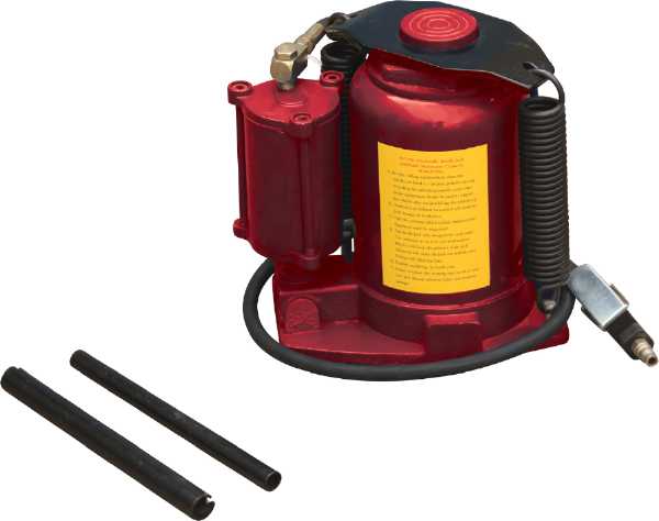 I
did a search and found a "30 Ton Pneumatic/Hydraulic
Bottle Jack" at Princess Auto for 130$C +25$ expedited parcel shipping.
(That was a great price, from a store I like, and for 48 pounds a great
price on the shipping! It was in fact cheaper than the 20 ton ones
(170$) and had better reviews. "3 available on line". Now only 2.) It
has two external return springs to retract it surely and quickly when
you've finished pressing.
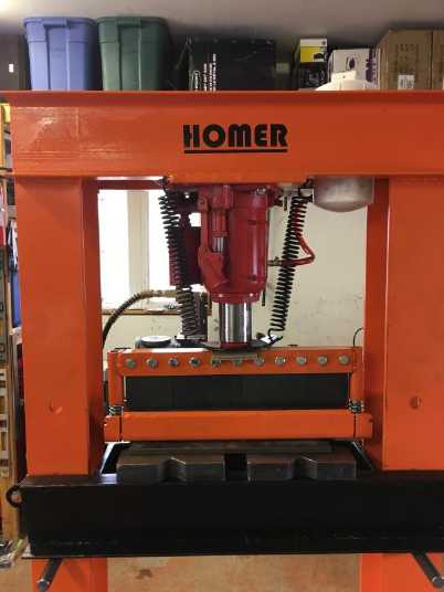 One reviewer had set his up in a shop press
just the way I
wanted mine. (wow, he even posted photos of it, pressing on a jig to
fold thick sheet metal or metal plate to 90 degree corners!) He had to
hook up a
hydraulic oil container to it to use it upside down. I don't see why I
wouldn't just use it right way up and have it press up against the top.
And if it pressed up against the original, upside down, jack I could
read the pressure on its gauge. (Or maybe I can hook the press'es guage
into the new jack somehow?)
That's another little piece to the puzzle of how to
produce batteries. There are more missing pieces, and more yet to get
decent production volumes.
But a few days later Princess Auto e-mailed that
they had canceled my
order. Apparently they didn't have three of them available after all,
or even one. For a while I decided to await further events.
Then on the 19th I looked again. eBay had some. HomeDepot
had a nice one for a good price. I couldn't get into my account "e-mail
unknown". Finally I noticed that I was at HomeDepot.com , not
HomeDepot.ca . HomeDepot.ca didn't have them, at any price. I went to
CanadianTire... they had them... 3 ton and 12 ton. Pretty lightweight.
Back to Princess Auto. This time the 20 ton model had just
come on sale
(as of 'tomorrow' but it was after business hours) and was now the same
price as the 30 ton one had been. It looked almost the same. Good
enough! I ordered it. It came.
Commercialization and the "Charge the
Future Challenge"
After sending out TE News #134 I set about filling in an
application for the Natural Resources Canada "Challenge", "Charge the
Future", which of course cut deeply into my project time - not to say
into my days and nights as a whole.
Near the start of August I had asked someone, Mike K., if
he
wanted to be involved. I went to their boat for dinner on the 10th. He
has had experience in setting up production equipment, and was building
a large and very nice workshop in town. I mentioned the need to compact
electrode substances from powder into "briquettes" and the bottle jack,
and he immediately had a couple of ideas for producing them that were
more elaborate and more rapid than things I had thought of. He also had
more focused, and doubtless more realistic, ideas about budget
requirements than I had and we discussed what I should be budgeting for
in the application.
Between him and his wife - and they only moved up here two
years ago about the same time as I did - they also seem to have
acquired a pretty good idea of "who's who" in Queen Charlotte and he
mentioned the name of a very good welder we might contract for specific
tasks in making production equipment.
I think we just might be a good match for the
commercialization endeavor, to set up limited production for 'beta
testing' and then perhaps a real factory. And with two of us, and money
to work with, we will surely stay much more focused on the goals and on
the work. (Especially me... Without losing all focus on other valuable
projects, it'll be "whatever I can do/need to do/should do" to get the
batteries out there.) Mike seems to have identified most of the missing
pieces of the puzzle (including marketing, which should be simple with
superior low cost batteries but shouldn't be taken for granted), and
either can fill them in or knows who can.
And now I'm trying to get as far as I can with research
and development before submitting the application. The zinc negative
electrode is pretty much 'nailed down', but the positive can use some
more experimentation as to manufacturing techniques and chemical
formulas, and so can the electrolyte.
http://www.TurquoiseEnergy.com
Haida Gwaii, BC Canada


 Jim Harrington pointed me to a 5-blade wind turbine (horizontal axis)
link from BangGood.com . There was a question/discussion space and
someone asked why 5 blades, and someone answered it. Apparently the
slower turning 5 blade types are quieter than 3-blades, and in light
winds deliver up to around 60% more output. Here I had always
understood that 3 blades was "the ultimate"... but apparently that's
only in sufficient wind.

 The output of the windplant was rated as 24 volts. That wouldn't do for
charging 36 volt batteries, so at the same time I ordered a DC to DC
up-converter of substantial power, also at BangGood, to bring it up to
about 40 volts.


 I heated the
water to boiling in a bread pan and sprinkled
the agar powder in. This made a lumpy mixture. Probably better to stir
the powder in and then heat the water. Then I added the zircon. (I
doubtless could better have done that before the heating, too.) I used
a bread pan because it's a good size and shape to dip an entire full
size electrode into to coat it. It's not easy to heat uniformly on a
burner, however.
I heated the
water to boiling in a bread pan and sprinkled
the agar powder in. This made a lumpy mixture. Probably better to stir
the powder in and then heat the water. Then I added the zircon. (I
doubtless could better have done that before the heating, too.) I used
a bread pan because it's a good size and shape to dip an entire full
size electrode into to coat it. It's not easy to heat uniformly on a
burner, however.![[graf]](MnPourbaix2.png) I
may have found a potential reason voltages seemed higher than I
had expected in my nickel manganates-manganese cells too: the voltage
of MnO4- would be around +.75 volts at pH 12. It was KMnO4 I put into
the cells to react and form the manganates. Perhaps that voltage also
applies to the manganates, rather than the nickel oxyhydroxide voltage
(~+.65) that I had expected. Add +.75 to -1.5 for metallic manganese
and you have about 2.25 volts. Even so they charged even higher, to 2.6
or so (dropping quickly to 2.4 volts under load), but most cells charge
somewhat higher than theoretical.
I
may have found a potential reason voltages seemed higher than I
had expected in my nickel manganates-manganese cells too: the voltage
of MnO4- would be around +.75 volts at pH 12. It was KMnO4 I put into
the cells to react and form the manganates. Perhaps that voltage also
applies to the manganates, rather than the nickel oxyhydroxide voltage
(~+.65) that I had expected. Add +.75 to -1.5 for metallic manganese
and you have about 2.25 volts. Even so they charged even higher, to 2.6
or so (dropping quickly to 2.4 volts under load), but most cells charge
somewhat higher than theoretical. If perhaps in
nickel manganates the form MnO4--- might for some reason
prevail, that would give +.15v + +.96v = +1.11V. That plus the roughly
-1.4v provided by the Mn negative would better explain cells that
charged up to 2.6 and even 2.7 volts. Was that the case?
 The experiment, now with a zinc negative, is the thing!
 I
used a flat rod to tamp the powder/soap mix with. It
seemed to get very solid as I tamped. I added just a bit at a time and
tamped some more. When I took the front off the compactor, it looked
just about how I wanted it. I trimmed off a couple of bulging corners.
I started to slide it off the back and it immediately cracked into 3.
Hmm... not really very solid after all. Maybe I should have used the
hydraulic press after all?
I
used a flat rod to tamp the powder/soap mix with. It
seemed to get very solid as I tamped. I added just a bit at a time and
tamped some more. When I took the front off the compactor, it looked
just about how I wanted it. I trimmed off a couple of bulging corners.
I started to slide it off the back and it immediately cracked into 3.
Hmm... not really very solid after all. Maybe I should have used the
hydraulic press after all? But if the mountain
wouldn't move, maybe put
the cap over the mountain? That worked quite well. The piece was
actually a bit long, but the edge of the shell just cut it off. So I
had a pretty much intact (if extremely fragile) briquette that filled
the shell, with an unbroken section of PP cloth in front of it to make
sure none could come out to short against the zinc.
 I wasn't at
all fussy about the terminal connection.
Something had to be done about that. It came to me that I could make a
hollow rectangular plastic tube, a terminal extension to the shell that
would contain the strands of graphite fiber and guide them up through a
hole in the lid. (In the next shell I ended up making a shallow trough
for the strands.)
 (14th) For the present I gathered all the
loose strands of graphite
into a short piece of plastic drinking straw. I found a piece of
graphite rod and sanded it down so it fit into the straw. Then I mixed
some epoxy and painted it in to fill the straw before I jammed the
graphite bit in. I put a weight on it to flatten the straw where it
would come out the slit in the lid of the cell. I hope the connection
is good.
 Later I
returned to it and decided to do the "full size"
electrode shell. All the minute adjustments would have to be done over
for it. I printed one. It looked pretty good. But I made the grille
bars
on 2.2 mm centers instead of 2.0, and without any change in the 1 mm
bar width, it printed them as two beads instead of one. Then instead of
printing the second layer as diagonals, it printed them square across
in the other direction. Those things were both notable improvements...
but who
would have guessed they would happen? Or... Aha! It was because I made
them
open at the top (for bubbles to escape). Just where the terminal tab
was on one side so the tops weren't open, it did them the old way. I'll
have to fix that. And I
want to make them still wider apart since the double trace actually
narrowed the bubble slots instead of widening them. And it didn't
"snap" together - it was a sloppy fit. And somehow I'd made it too
short.
 On the 15th I mixed some potassium chloride solution, 35 g
of KCl in 100 cc/ml/g of H2O. I put a new piece of plastic in as a
slightly thinner case filler than before since the plastic shell
electrode was fatter than the other ones. It took a little under 20cc
to fill the test cell. The solution turned purple from the potassium
permanganate. But only a few grams per 100 cc will dissolve into water.
The rest should remain solid - and jelling it should help make it
permanent, too. (Perhaps in times past this purple herring distracted
me from realizing it was my negative electrode causing the self
discharge.)
 On the night
of the 17th I did the shell, and ended up
after several tries with a 'porous' shell that snapped together,
perhaps a bit loosely. (Better than the previous ones that that
wouldn't quite go) It had a 3-sided plastic terminal tab to bring the
long strands of carbon fiber up to a terminal. I figured the strands
could protrude up from the current collector through the shallow
"ditch", some heat glue or epoxy could seal it at the top of the case
to keep electrolyte away from the metal above, and I would bolt a piece
of metal to the plastic tab with the strands pinched between. or
better, two pieces of metal (thin and thick) with the strands pinched
between them.
 Then I decided
to make a new zinc electrode as well. The
other one was still working fine, but it didn't have much fuzzy
plating. A
thicker one should have both more amps and more capacity. (Of course,
it was clearly the dry cell nickel oxides bits electrode that was
limiting the capacity, and the poorly compacted nickel manganates one
didn't seem to work well at all.) After plating it weighed 7.8 grams.
Assuming it was about 4.4 before, that's 3.4 grams of fuzzy plating
adding a theoretical 2.8 amp-hours, 1.4 to each side.
 I
note that it is has been said that any metal but nickel
will oxidize and corrode away in the 'positrode' of an alkaline
battery. Only nickel "passivates" at pH 14 (by forming an attached one
molecule thick oxide layer "skin", similarly to aluminum or titanium at
pH 7). Nothing I've read anywhere indicates anything else (besides
graphite/carbon) will work. But after all these weeks in the battery in
KOH solution, my cupro-nickel (70:30) current collector piece looked
almost like new including under a microscope, except that some patches
(those not contacting the electrode chunks) looked slightly coppery -
or perhaps it was a very slight tarnish - and others (mainly in good
contact
with the electrode bits, but also the whole back side) more the
original silvery. (There was a faint horizontal line across the back,
perhaps where a piece of plastic had once had its edge, or a half full
electrolyte level.) (Monel, which has a higher nickel content, probably
wouldn't tarnish or discolor at all.)
 I
did a search and found a "30 Ton Pneumatic/Hydraulic
Bottle Jack" at Princess Auto for 130$C +25$ expedited parcel shipping.
(That was a great price, from a store I like, and for 48 pounds a great
price on the shipping! It was in fact cheaper than the 20 ton ones
(170$) and had better reviews. "3 available on line". Now only 2.) It
has two external return springs to retract it surely and quickly when
you've finished pressing.
 One reviewer had set his up in a shop press
just the way I
wanted mine. (wow, he even posted photos of it, pressing on a jig to
fold thick sheet metal or metal plate to 90 degree corners!) He had to
hook up a
hydraulic oil container to it to use it upside down. I don't see why I
wouldn't just use it right way up and have it press up against the top.
And if it pressed up against the original, upside down, jack I could
read the pressure on its gauge. (Or maybe I can hook the press'es guage
into the new jack somehow?)