Turquoise Energy News #136
covering
September
2019 (Posted October 3rd 2019)
Lawnhill BC Canada
by Craig Carmichael
www.TurquoiseEnergy.com
= www.ElectricCaik.com
= www.ElectricHubcap.com
Month In "Brief"
(Project Summaries etc.)
- More Battery Experiments - Handheld Bandmill, Milling Lumber -
Polyurethane Paint on Polypropylene Cloth: Modern version of cellulose
dope on canvas for aircraft? - Five Blade Windplant
In
Passing
(Miscellaneous topics, editorial comments & opinionated rants)
- Hearing Improvement? - Fatal Financial Flops - Insane Acts: a Hint of
Twisted Rational Purpose? - Small Thots - ESD
- Detailed
Project Reports
-
Electric
Transport - Electric Hubcap Motor Systems
* Ground Effect Vehicle (R/C Model)
Other "Green"
Electric Equipment Projects
* Working with the Handheld Bandsaw Mill (& Alaska Mill)
Electricity Generation
* 5 Blade Windplant
* My Solar Power System: - Monthly
Solar Production log et cetera - Six month summary, notes.
Electricity Storage
Turquoise Battery Project (Mn-Zn or Ni-Zn in Potassium
Hydroxide electrolyte ?)
* Nickel Manganates Electrode Toasting - Backing Up: What Works? -
Experiment #1 - Printing An ABS Electrode Shell - Experiment #2: Nickel
NiOOH electrode - Extracting MnO2 from old dry cells - Experiment #3:
Jelled MnO2 - New Electrode Compactor, Punch and Die - Sewing Carbon
Fiber Cloth - The Electrode - 3D Printed Battery Cases (Deja Vue?) -
Compactor Die Slit for Graphite Foil Terminal Tab - MnO2 Electrode with
Loose Carbon Fibers - Painted Zinc Electrode - A Better MnO2 Current
Collector: Conductive Graphite Painted Copper Fingers - It's a Product!
- Cell with Graphite Coated Copper Current Collector (canceled) -
Second Cell with Calcium Oxide instead: Assembly & Testing
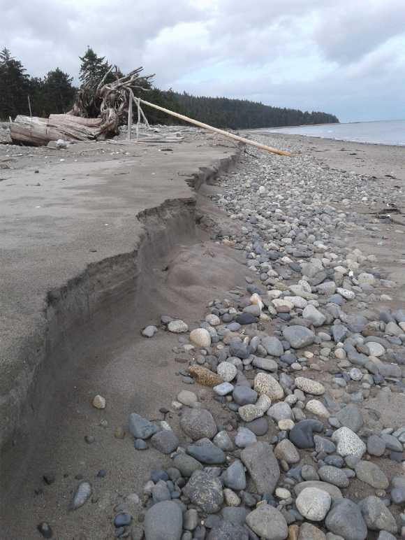 The beach that changes with every tide
sometimes gets some unusual formations.
The beach that changes with every tide
sometimes gets some unusual formations.
Here calm weather at a quite high tide deposited much sand high up on
the beach.
On another day rough waves washed it away to expose rocks underneath,
but the
tide wasn't as high - the waves only got up 'so far', leaving a foot
tall sand 'cliff'
above high water. It was there for several days until a higher tide
rearranged it
all again.
More Battery Experiments
As one might expect with good progress and the possibility
of funding, yet another month has been almost wholly devoted to battery
experiments, design and construction. The cells weren't exactly giving
high currents but I decided that anyway the simple and ready market to
enter into was economical bulk electricity storage rather than try and
break into the electric vehicle market, which requires extreme currents
of the batteries. As someone showing zinc-bromide flow batteries in
Australia said of his, these would be marathon runners, not sprinters.
Unless I could come up with a fabulously conductive positive current
collector that wouldn't oxidize away. That may be a last major research
goal. (In fact, after some experiments with graphite paint on copper, I
tried something novel in a cell on October 1st - copper calcium oxide.)
Cell Case with "porous"
plastic separator and a glue-in terminal piece
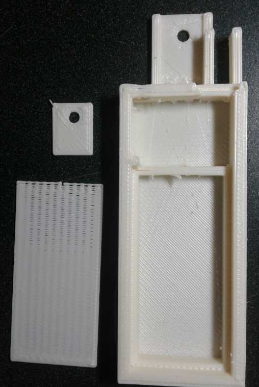 I
went from glued together cell cases of ABS sheets to custom 3D printed,
but I had problems with them leaking. I thought I hadn't sealed it
around the seam, and I made the next lip wider. It wasn't until October
1st I put together a second cell. I hoped this would be "the" cell,
which would go on working, with good current flow, for as long as I
cared to test it. But it seemed to leak too. This time some calcium
oxide patches on the back face which could only have come from inside,
made me realize the liquid was actually seeping right through the 3D
printed face of the cell! (I 'glued' a piece of ABS sheet right over
the whole face to stop the leaking, but it didn't work. They must leak
around the edges too.)
I
went from glued together cell cases of ABS sheets to custom 3D printed,
but I had problems with them leaking. I thought I hadn't sealed it
around the seam, and I made the next lip wider. It wasn't until October
1st I put together a second cell. I hoped this would be "the" cell,
which would go on working, with good current flow, for as long as I
cared to test it. But it seemed to leak too. This time some calcium
oxide patches on the back face which could only have come from inside,
made me realize the liquid was actually seeping right through the 3D
printed face of the cell! (I 'glued' a piece of ABS sheet right over
the whole face to stop the leaking, but it didn't work. They must leak
around the edges too.)
Obviously this is just a minor glitch. I already know I
need to get new software running to print better. Some time soon I'll
have worked out all the glitches and can start thinking of production.
It didn't happen in September. October is the month to apply for the
"Charge the Future Challenge" from Natural Resources Canada, and I'll
have to do that without having every detail wrapped up.
Handheld Bandmill, Milling
 I
finally, months late according to my schedule but at least a year late
according to the amount of rot and bug tunnels in the spruce log, I got
back to milling the last spruce log from the four trees I had cut down
in summer 2017 when I moved here. I made wood and learned a bit more,
and came up with a small change to make (detailed report).
I
finally, months late according to my schedule but at least a year late
according to the amount of rot and bug tunnels in the spruce log, I got
back to milling the last spruce log from the four trees I had cut down
in summer 2017 when I moved here. I made wood and learned a bit more,
and came up with a small change to make (detailed report).
I showed the mill working to a neighbor. He was impressed
and thought he would like to make one himself. I think I should do some
sort of instruction guide on how to build these saws. There have been
enquiries about doing so, and it would be a lot easier if a person
knew, for example, the dimensions of various parts, and how they went
together. Somehow I can't see trying to set up a business of making and
selling them from scratch. I'm just not "DeWalt", "Husqvarna" or even
"Yardworks".
Polyurethane Paint on Polypropylene
Cloth - Modern version of cellulose dope on canvas for aircraft?
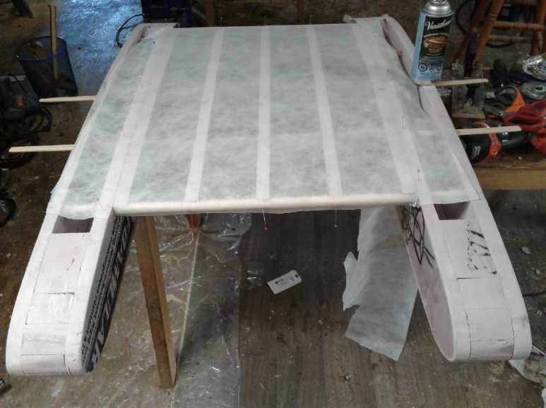 I
had been planning on epoxying the fabric, but my brother said he was
making a canoe and he was going to try painting varathane on PP cloth.
I thought that might be worth a try myself.
I
had been planning on epoxying the fabric, but my brother said he was
making a canoe and he was going to try painting varathane on PP cloth.
I thought that might be worth a try myself.
Varathane (I believe) is polyurethane. I had a pretty full
spray can of it. I cut a piece of featherweight PP fabric and pinned it
on the top of the wing on the model ground effect craft. Then I sprayed
it. It didn't seem to do much. 7 or 8 sprayings later, I could feel my
breath warmth much less when I put my hand behind and blew through it.
But the spray can was empty. A few more coats and it will probably be
airtight. I wasn't expecting to have to go on day after day, and the
month ended with me still waiting for paint to dry. And will it really
be lighter than epoxying it?
I would note that the varathane doesn't shrink the cloth
like dope does to organic fabric, and it doesn't glue the fabric to the
model, either to the styrene foam or to the wood. I still have a piece
of loose cloth simply pinned to the model. At least if I decide I don't
want it, it'll be no problem at all to remove and discard.
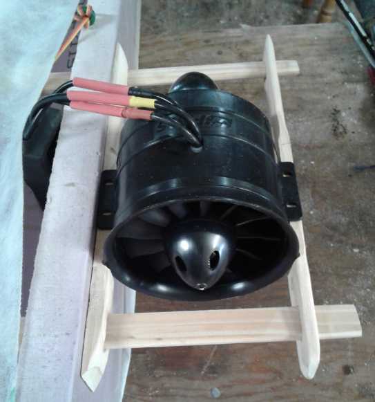 I cut and shaped pieces of wood to mount one of
the "outboard" ducted fans.
I cut and shaped pieces of wood to mount one of
the "outboard" ducted fans.
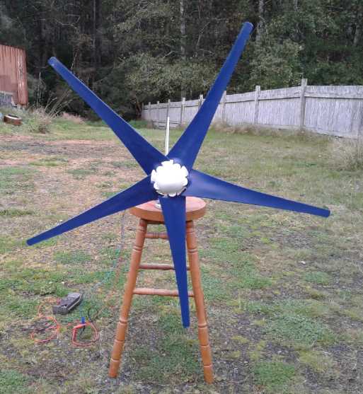
Five Blade Windplant
 The 15th was sunny and warm. I milled some lumber. The next two days
were cloudy and windy and cold. I lit a fire, looked at the waves and
wondered where my 5 blade windplant was. Tracking said it was en route
from China to Canada.
The 15th was sunny and warm. I milled some lumber. The next two days
were cloudy and windy and cold. I lit a fire, looked at the waves and
wondered where my 5 blade windplant was. Tracking said it was en route
from China to Canada.
Finally an e-mail on the 30th said it was at the post
office, and I got it, assembled it and tried it out on October 1st,
which happened to be quite windy. It spins well and looks like it
should put out some power - how much will remain to be seen after it's
installed and some metering is put on it.
To slow it down and to keep it from spinning up, I moved
the meter from AC Volts (18~20 volts between two phases) to AC Amps.
This shorted the output, which hit about 3 amps as the blades braked.
I keep thinking of not bothering to record my solar power
collection (now having logged it for 6 months - the best 6 of the
year), but adding the windplant, and moving or adding solar panels,
might bring some new 'revelations', so I've decided to keep going.
Finally, Dr. Evans sent me another very generous donation of $500
US. And an interesting (patented) circuit diagram that may have
application in switching coils in unipolar motors. Thank you Dr. Evans!
In Passing
(Miscellaneous topics, editorial comments & opinionated rants)
Hearing Improvement?
We hear that hearing, once lost, doesn't improve. But on a
short time scale we know that's not entirely true: after being exposed
to loud noise for a while - a noisy work environment or a loud concert
- our hearing is dulled and our ears may ring, but the next day it has
recovered (except maybe for some of the tinnitus) and we hear better
again.
In the long term, our hearing doesn't seem to completely
recover. I've lost hearing in concert bands and orchestras, sawmilling
and workshop work, and especially I lost some making alto recorders
from 2003 to 2007, testing the sound and getting the tuning just right
over three octaves. Except once (~1991) I have never had a hearing test
with results better than the previous one.
But, our environment is never very quiet. There are noisy
cars and traffic, noisy heating and ventilation systems, noisy computer
fans, humming or buzzing electrical equipment, refrigerator, heat pump
and air conditioning compressors, radio or other music sources, and so
on. Our hearing just doesn't get that truly quiet time in which to
fully recover, and over the years we lose more and more, especially of
the high frequencies that surround us seemingly all the time.
I looked on the web to see if anybody had anything or any
technique that might help, and I came across the idea of putting
vegetable oil in your ears - olive oil, peanut oil or whatever - with
an eyedropper. At first glance that sounded silly. But it was from more
than one source. I started dripping it in my left ear to try it out.
(Then I just let it drain. A bit of tissue in the ear for a minute
soaks up the drop or two that comes out.)
After a few months I went to an audiologist and had my
hearing tested. He couldn't see any reason it would help either. The
only effect should be to help loosen and expel wax buildup.
For whatever reason I had continued to put in the oil even
on the morning of the appointment. First he looked and said he could
only see the center of my left eardrum because the oil and wax was
built up around the sides. The right eardrum was clear. Then the test
showed my left ear as being worse than my right ear instead of better,
in fact, it had degraded into the mildly impaired range at (??) 2 to 8
kilohertz. In 2012 it was on the edge of impaired. (He said he'd e-mail
me a copy of the results. Where is it?)
I left his office disappointed, but gradually I started
realizing how it works. With the oil built up around the sides, the
eardrum is less responsive, especially to high pitches. So basically it
acts like a high-frequency selective "earplug" to reduce the noise
level that you hear, in effect to make the environment with all those
fans and things quieter. Hence my 'impaired' range test results. It was
as if I was hearing through an "earplug". The quiet environment helps
give the ear quiet time to recover (very, very gradually).
This says that the efficacy of the treatment is probably
timing dependent. There's little point putting the oil in before bed If
your bedroom is quiet - no noise is present to be filtered out. The
better time would be in the morning, and more especially before doing
anything noisy, and probably more than once a day if you are, or if
your environment is noisy.
But results will also depend on your noise environment(s)
- when and how much and what sort of "background" noise you are daily
exposed to. Of course if there's a fan in your bedroom or noisy traffic
right outside or other conditions, before bed might be a good time to
put in oil after all. And personally, I would settle for a fridge that
used twice as much electricity if it didn't have a compressor. (and two
noisy fans. Something or other is running about 3/4 of the time.) I've
always felt that fridges make a kitchen from a quiet space into an
unpleasant noisy one. (In fact sometimes I close the kitchen door to
keep the sound out of the livingroom.) If you haven't noticed your
fridge, could it be there's more noise in your environment than you
have been aware of?
Insane
Acts - a Hint of Twisted Rational Purpose?
Around 1970(?) someone put poisoned pills in tylenol
bottles in a grocery store or two. The people who bought those bottles
were poisoned and died. (Ever since that, all packages sold in stores
have had some sort of "safety seal" that has to be broken to open the
bottle or get into the package.)
What was the motive behind this mad act? It plays on the
mind because one can't come up with anything more than "Whoever did it
was nuts." Could there be any meaning at all behind the madness?
But tylenol (acetaminophen) is said to cause 50,000 deaths
per year. It is contained in various different pain killers with
different names, and those who don't bother to read the fine print
often don't realize they've exceeded the maximum dose by many times,
getting it in several "different" pills. It also evidently damages the
liver if taken when there is alcohol in one's system.
Here's my theory: The poison pill pusher had a loved one
who died as a result of tylenol overdose. In order to highlight to the
world the dangers of tylenol, he would have people die of it until
"they" were forced to withdraw it from the market. His evil act was
miscalculated because it was quickly realized that the poison wasn't
the tylenol. (AFAIK the culprit was never caught.)
Then there was the other devious, seemingly insane thing I
was going to write about... didn't involve murder... I had them both
clearly in my mind when I started... now what was it?
(I'll decline to comment on false flags, and on mass shootings.)
Fatal
Financial Flops
In 2008 in the
"TARP" bailouts a staggering amount of money was spent bailing out the
banks. Lehman Brothers failed for want of a half a billion dollars
(well, 620 million). Foreclosing on mortgages (even illegally in a
spree of bankster lawlessness) the banks then ended up owning much of
America's real estate. not just owning the mortgage, but actually
owning it outright. which they kept off the market to prevent house
prices from going back to pre-bubble levels. People everywhere lost an
average of 30% of their wealth in a short time. No one bailed the
citizens out. The big bankers took their usual annual bonuses of tens
or even hundreds of millions of dollars each - now paid for directly by
taxpayers who were losing everything.
Then it was a big scandal in Canada, retroactively, when
accountants discovered later that from 2009 to 2012 the big Canadian
banks had likewise been bailed out to the tune of 112 Billion $. (So
much for "Canada's sound banking system", which effectively disappeared
in about 1972, according to former cabinet minister from those times,
Paul Hellier.)
Then there was "QE3", the US Federal Reserve's ("Fed") big
free money printing program to the tune of 80 BILLION DOLLARS PER
MONTH! For comparison, the total "base currency" in circulation in
about Y2K was 820 billion. They were now printing more money than that
each year! That money was used drive up the prices of assets and thus
further dilute the value of people's savings - those that still had
savings.
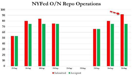 Then along comes September 2019. The "Fed" quietly starts printing 75
BILLION DOLLARS PER DAY to bail out the again failing banks. (Really
they've been insolvent since 2008. I imagine that since the huge bubble
was blown up, failing businesses, failing stores, a failing housing
market and consumer credit defaults have all contributed to an ever
worsening income picture) They said they would continue printing
$75,000,000,000 - per day - "until October 10th". That totals to far
more money than all that was in circulation in 2000. It's as much money
as in a year and a half of "QE3", which people feared would by itself
destroy the value of the US$. All in 3 weeks. And a few days into it
the banks were asking for even more. (Can I get a loan at the Fed
"Discount Window" at 2% too?)
Then along comes September 2019. The "Fed" quietly starts printing 75
BILLION DOLLARS PER DAY to bail out the again failing banks. (Really
they've been insolvent since 2008. I imagine that since the huge bubble
was blown up, failing businesses, failing stores, a failing housing
market and consumer credit defaults have all contributed to an ever
worsening income picture) They said they would continue printing
$75,000,000,000 - per day - "until October 10th". That totals to far
more money than all that was in circulation in 2000. It's as much money
as in a year and a half of "QE3", which people feared would by itself
destroy the value of the US$. All in 3 weeks. And a few days into it
the banks were asking for even more. (Can I get a loan at the Fed
"Discount Window" at 2% too?)
What happens after October 10th? Will the banks
miraculously need no more, printing will stop, and the "Fed" will be
able to close out its mushrooming balance sheet? Hah!
 How huge will the toxic balance sheets of the
central banks mushroom out to?
How huge will the toxic balance sheets of the
central banks mushroom out to?
[This is a huge (10"?) poisonous amanita muscaria. If it was a central
bank
it might just keep inflating until it blocked the whole highway!]
Have they gone off the deep end this time? How much longer
can the whole pyramid scheme financial system carry on? Will there be
hyperinflation, or will the banks simply close their doors? If the
latter, there may be no money except the paper in peoples' wallets (and
in odd on-line places like Paypal accounts), which would cause sudden
drastic deflation. But how can it possibly end except in chaos?
One financial analyst, Rob Kirby, said that if the "Repo"
printing ends in a few days things could go smoothly for a while
longer. (and looking at it again later, it just might. Maybe!) But he
also points out that this is what they did just prior to the 2008
crash, and he thinks they'll keep doing doing "whatever it takes" -
whatever they can - to keep everything going even a few more months.
Below is what another well known financial expert had to
say about it. Bear in mind that both of these financial people are (or
have come to be) firm believers in gold as money, but I doubt if
they're too far off. Timing of events is always anyone's guess.
Amazingly things have held together so far for over a decade since the
"financial crisis" even though none of the problems were fixed:
[Via Greg Hunter's USAWatchdog.com & Zerohedge.com]
Financial and precious metals expert Egon
von Greyerz (EvG) says the signs abound that we are nearing the end of
this global fiat money experiment, while central bankers are befuddled.
EvG explains, "The central banks are panicking..."
"They don't know what to do anymore. They are just
starting to print money and with the euro on a daily basis...
Europe is starting QE ["quantitative
easing", AKA money printing] again with $20 billion a month, but
that's nothing compared to what is coming. . . . The panic that started
with central banks in the summer in late July and August was, to me,
the first step towards total chaos in the world that we will be seeing
in the months and years to come. They (central bankers) see it
clearly.
They know the banking system is absolutely on the
verge of collapse. They know Deutsche Bank (DB) and CommerzBank,
too, are down 95%. If you show this chart to a child and ask
where is that likely to go, it is likely to go to zero. DB, with their
$50 trillion in derivatives, there is no chance they will survive. Of
course, Germany and the ECB [European central bank] is panicking
because that will affect the whole banking system worldwide. This
is why they have started to print money now because there is a massive
liquidity problem, and that's Germany, which is the best country in the
EU from the point of economics. Then you take Italy, Spain,
France and Greece and they are in a real mess.
This is why the whole system is on the verge of
disappearing into a black hole... With the U.S., there is massive
liquidity pressure there too."
The massive amount of money printing to keep the fiat system afloat is
just starting. EvG contends, "This is just a practice round..."
"This is just more money at this point. The
balance sheet . . . of the Fed is going to go from around $4 trillion
to $40 trillion. It is going to go to $100 trillion before this
is over. So, right now, they are just practicing a bit because they are
going to put the pedal down to the bottom very soon...
There is no other way to save this system, it has
gone too far. I am not a pessimist. I don't want to see the end of the
world, but you can see their actions. You can see that now there is
absolutely no way out. The only thing they know is to print money. They
have already reduced rates to zero or negative, which is a disaster in
and of itself."
EvG predicts, "All of these bubble assets that are based on just credit
and credit expansion are going to implode measured in real terms,
measured in gold."
Of course, most of these experts are saying one should
have precious metals (the actual metal, in your possession - and very
well hidden I would add) in one's portfolio, since whatever happens to
fiat currency, those coins and bars will retain some real value. (I
wish I had bought some rhodium 5 years ago. It's gone from what? 1500
$CA/ozt, to 5000 $. Silver and gold have gone up a little, and will
probably go up more, platinum has been flat, palladium has doubled...
but rhodium... ooh! But one rarely can predict such specifics very far
in advance. As usual I digress.)
Small
Thots
* I found my fourth 'impact resistant' 6 oz Duralex glass from the set
of four bought in 1977. It wasn't broken or gone after all. (It was a
lone item 'abandoned' in the dishwasher, which I hardly ever use.)
* On the 18th I noticed a battery recycling bin outside a thrift store.
I found 5 good looking alkaline "D" cells and a couple of "C", to
extract the manganese oxide from. I tested them at home. The 5 "D"
cells were all like new: ~1.59 volts and they put out over 7 amps
shorted! Maybe I'm in the wrong business... I could probably get 2 or 3
dollars each for them, and if some of the big stash of "AA" and "AAA"
cells were likewise good, maybe a buck or more. Move over, pop bottle
collectors!
* The "C" cells were rather interesting. One was only 1.47 volts but
put out almost 4 amps when shorted. The other was 1.53 volts but put
out less than an amp. I tried it a few more times to be sure and it
started doing around 1.5 amps.
* With the idea of recycling waste clear plastic into greenhouse
panels, I had started saving clear packages, and getting the labels off
them. Soon I had a surprisingly large mound. Finally I decided saving
them was dumb: If I created a means to turn them into panels, all that
would be needed would be a recycling bin for each type and volunteers
would put more in in a day than my whole pile of clutter, being glad it
would go to a good cause. I threw them into the woodstove on a good
fire (a couple at a time) and incinerated it all - and got back the far
corner of the kitchen to set up the LED indoor garden for the winter.
* Concerning the weather these days, someone put it this way in a
comment on Youtube to a Video by Paul Beckwith:
Our New Normal Since 2000
Record Rain has been 29 - 600 % Increase in Rain
Record Rain, Record Snow,
Record Highs Record Lows
Record Winds, Record Waves
Record Fires, Record Floods,
Record Volcanic Eruptions.
Record Hurricanes, Record Tsunamis,
Record Typhoons, Record Earthquakes,
Record Mud-Slides, and Record Sea Surges.
Record High Tides, Record Sea Level Rise.
I thought he must surely have covered it all... then I
noticed he had missed record tornadoes, record droughts and record
hailstones.
ESD
(Eccentric Silliness Department)
* Okay, I'm always behind the times if I'm not ahead. Totally out of
sync. I never did get a pet rock.
- Where do you get a pet rock? In a pet rock quarry.
- Where do you keep a pet rock? In a rock garden.
- What do you get when two pet rocks rub together? Gravel.
* A vice is supposedly used to hold things. I find mine are devious
de-vices, always letting things slip out no matter how tightly closed.
* The density of the Earth is about 6. The other planets are under
density 4. Most of the spheres orbiting Saturn are only about 2 while
Saturn itself is less than one. Could Saturn be placed in water, it
would float. The Earth is the densest thing in the solar system except
for the density of we who inhabit it.
"in depth reports" for
each project are below. I hope they may be useful to anyone who wants
to get into a similar project, to glean ideas for how something
might be done, as well as things that might have been tried or thought
of... and even of how not to do something - why it didn't
work or proved impractical. Sometimes they set out inventive thoughts
almost as they occur - and are the actual organization and elaboration
in writing of those thoughts. They are thus partly a diary and are not
extensively proof-read for literary perfection, consistency and
completeness before
publication. I hope they add to the body of wisdom for other
researchers and developers to help them find more productive paths and
avoid potential pitfalls and dead ends.
Ground
Effect
Vehicle
(first
the
R/C
Model)
On the (ahem) 24th I
finally got back to this project. Luckily it seemed pretty
straightforward - no vital details to forget by setting it aside for a
while (repeatedly). And somehow with every delay has come some new idea
for it. The plan until now had been to use the thin but strong
polypropylene cloth and coat it with epoxy, and I had done part of the
bottom of one hull. That was my idea of a modern version of the
cellulose based dope (lacquer) on canvas or cotton of early aircraft
coverings. The epoxy was much heavier than the cloth it was
impregnating.
But my brother had called some days previously, saying he
was going to make a foam core canoe. For the skin he was planning to
use polypropylene cloth with varathane. Instead of epoxy, varathane? As
I recalled, varathane was in fact a polyurethane paint.
The idea took hold. I had a can of varathane spray paint.
What would happen? If it worked, it would probably be the lightest wing
covering imaginable. At first I was just going to try out a small
piece, then I decided I might as well do the whole top surface of the
wing. (I trusted that I could rip it off again if I didn't like it.) I
cut a piece of the paper thin white PP cloth (with some extra margins)
and pinned it in place, then I sprayed it.
A while later I tried to blow through it. I could feel my
breath on the other side. I sprayed on another coat. After 7 or 8 daily
coats the month ended. The spray can was about empty and I could still
feel my breath, although much reduced. A few more coats should do it.
HOW many coats of varathane to make the
lightweight fabric airtight?
I am thinking it might be better to epoxy the cloth,
sitting loose on a piece of plastic (LDPE), squeegeeing out all
possible excess, and then pinning it onto the model. The epoxy would
glue it on. (Maybe add some epoxy to the contacting surfaces of the
model to be sure there's lots there?)
While I was at it, I shaped a couple of pieces of wood to mount one of
the ducted fans on. I cut similar pieces for the other side but didn't
get them shaped up. I cut/milled slots in the pieces with my milling
machine, which had decided it would work fine on this occasion.
(Nothing to see here... but next time I tried it it wouldn't run again.)
Other
"Green"
Electric
Equipment
Projects
Working with the
Handheld Bandsaw Mill (& Alaska Mill)
I wasn't going to write up anything about this, but it
seemed I had taken a few pictures while I was milling and had just a
couple of little things to say.
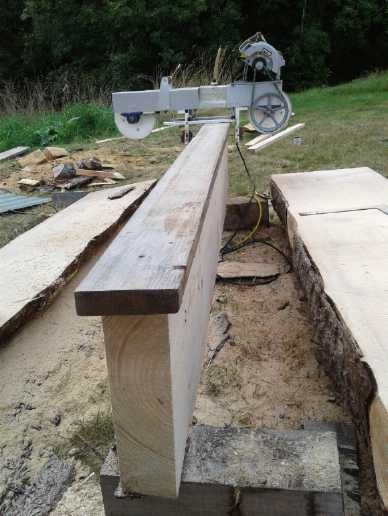
 This big spruce log, still 48 feet long (after
about 22' was milled off the top in 2018),
This big spruce log, still 48 feet long (after
about 22' was milled off the top in 2018),
the last one cut down in 2017, is rotting! Bug holes riddle the sapwood.
It can't be allowed to lie out on the ground a third winter.
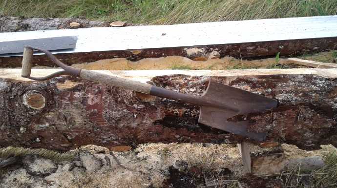 Log Tip: Way back in 1972 someone showed us how
to peel bark with a sharpened square shovel.
Log Tip: Way back in 1972 someone showed us how
to peel bark with a sharpened square shovel.
This spruce bark seems to dull the saws rather quickly, so it can be
worth peeling it off.
(I've had this shovel since about 1978.)
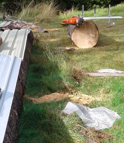 A 12' section, an 8' section, and now just 28
more feet to go!
A 12' section, an 8' section, and now just 28
more feet to go!
(a 16' and a 12' - from the fat but end)
...as the weather heads into fall. Rain & clouds started on October
1st.
I buck the log segments into 4", 6" or 8" thick
slabs (cants) with the Alaska mill,
then slice those into boards of those widths with the handheld
bandmill, 1", 1.5" or 2" thick.
The thin-band electric bandmill utilizes the whole of the wood
with negligable sawdust and waste, using no gasoline and oil.
I still had a lot of milling to do by the time October
rolled around. On October 2nd I sharpened a band and cut three 16 foot
2 by 4s, but it still didn't cut very well and it was hard going.
Wasting my time... Time to toss it and break out a new one! The next
day a new band was somewhat faster. But part of the problem had been
the V-belt slipping because the skillsaw was at its maximum height
adjustment. Removing a couple of links from the link belt so it could
be tightened properly surely helped too. (Maybe I won't throw out that
old band just yet.)
I've decided I want to change the guide wheels - the
little 22mm ball bearing units are plain crappy and I've used them all
up or worn them out. Maybe I can make them instead with larger diameter
bearings, wide enough to be the wheel. Then there'd be a thrust
bearing behind between two washers, to get the "railroad wheel" edge
since the washers gradually wear out and it's a pain welding new ones
onto the wheels. Then again, bearing rims won't have sawdust relief
slots in them.
Someone suggested mounting a brush or wooden block to
brush or scrape off sawdust off the inside face of the band. That's
probably a good idea.
5
Blade Windplant
On the evening of September 30th there was (at long last) a notice in
my e-mail that 'a package' had arrived at the post office. The
windplant was the only thing I was expecting and I picked it up the
next day. (Call it September 31st.) I opened it and put the blades on.
Then, as it was a blustery day (and spitting rain), I took
it out to the porch, where fitful gusts didn't start it turning.
Location is everything!
At the top of my driveway where the wind funnels in, I set
it on a stool and held it upright. Here it ran. It seemed to barely
start, but as it sped up, it became more and more energetic.
Windplant propellers are designed for spinning "at speed",
and are not very effective for starting up. When they're stopped, only
the air passing very close to each blade has much push on them, and at
a poor angle of attack. That would explain why they are reluctant to
start up in low winds, and why a 5 blade would be better than a 3. At
speed, all the wind passing the area swept by the propeller blades, the
whole circle, is utilized. The 3 blade has to spin fastest to catch it
all, while the 5 blade (all else being equal) is just 3/5 of that
speed. The five blades have more drag, which is said to limit the power
in higher winds. (Come to think of it, why should that be: since the
five blades are only spinning 3/5 as fast, shouldn't each blade have
less drag by virtue of going slower? Anyway I would rather have a
little power in lower winds than extra power in high winds, because low
winds are much more frequent.)
Soon the tips were making a furious whizzing noise that
said "I dare you to put your fingers in here!", and the voltmeter
across two phases reached 20 volts AC. (If it's quieter than a 3 blade,
it's only by degree, not a big jump. One expects 6, 7, 9 and 11 blades
should have progressively less high pitched "whizz".) To slow it down I
moved the meter leads to 'current', which shorted the two phases. It
put out up to 3 amps AC or so as it lost its speed. I could estimate
that the "1200 watt" windplant might do 40 or 50 watts if the
controller had been connected and there was a load, but I could be way
off. The good part was that it could do it whenever it was windy, day
and night. Several solar panels weren't doing any better in the rain
and clouds that afternoon.
That was all I had time for. I'd have liked to install it
and wire it in, because the solar was (for the second time) so poor
that I couldn't run the kitchen hot water heater with four panels
dedicated to the DC system. In addition to it getting late in the day,
I didn't want to climb up on the roof in the wind and rain, and I
didn't want to run the wiring from one end of the long, low attic to
the garage at the other end (ever, really). (And I only came up with a
good plan for mounting it on October 3rd.)
One could also estimate theoretically by size. The radius
from the hub to the blade tips is .64 m. The area is pi * R^2
or 1.29 sq. meters. (Ooh, more than a toy!) The formula is:
P = 1/2 * Rho * A * V^3.
1/2: from the general formula: e = 1/2 * M * V^2
P: power (in watts)
Rho: weight (of air in Kg/m^3)
A: area (square meters)
V: velocity (in meters per second)
(How metric makes all that work with no weird conversion constant "K"
except times 1/2, I don't know. Whoever designed some of these units
evidently knew just what they were doing!)
At a cut-in speed of about 10(?) Km/Hr:
P = .5 * 1.2 Kg/cubic meter * 1.29 sq.m * 2.78 m/sec ^3 = 16.6 watts.
That would be the total power in the breeze. A propeller
should capture a bit less than 1/2 of that. Gosh, we're down to 8
watts. Of course, a 20 KmPH wind would have 8 times as much, over 60
watts, and 30 KmPH would be 27 times - around 200 watts. Well, we knew
stronger winds were a lot better. It'd take a 50 KmPH blow to get up
near the 1200 watt rated power of this unit. That does happen -
thankfully rarely.
Here again we might do much better with a venturi. If we
made one with a mouth and or an exit that was say 3 meters diameter and
shrinking down to 1.29 meters at the (?)throat, in theory over 5 times
as much air would be going past the propeller. To do that it would have
to go 5 times faster? No doubt there would be a lot of frictional
losses and it wouldn't be 5 times the air speed, but there should be
substantial power to harvest in a 10 KmPH breeze instead of almost
nothing. Then too, one could place shutters in front of the opening so
that if the wind was too strong, it would lift them against gravity (or
against a spring) and blow them shut, reducing the opening and
protecting the windplant. An experiment with some lumber and sheets of
plywood or just plastic might be worthwhile.
---
In my observations of two small (3 blade) windplants, I
would see them start up, start whizzing, and then stop again. Hmm, just
like when I shorted the output? Trees were blamed, but the same effect
might be had if their control systems ask a bit too much, overloading
them, and so the blades stall. We'll see what happens with this one!
My
Solar
Power
System
Y-Solar Grid Tie Inverters
Someone on youtube put out a video expressing concerns
that these Chinese grid tie inverters, technically not approved by UL
or CSA, might be dangerous to electrical linemen. Obviously if the
inverter is working right, it is perfectly safe. Like all grid tie
inverters, it only puts out electricity each 120th of a second if it
senses voltage is already present. Then it synchronizes its own output
to that signal, adding current. I have given it considerable thought,
and I can't imagine a scenario where the inverter was malfunctioning
and yet would put out a working signal into a dead line.
But I have another complaint with them: lack of
performance. It's not that they don't effectively utilize the panel
energy... under ideal conditions.
The way they try to put out power seems to be to assume
they can put out "X" watts. Then when there isn't enough power from the
panels for that, they only put out the power for a brief period and
their capacitors become discharged. Instead of adjusting, they stop
entirely and then come on again trying out a lower power level. When at
last they are very near the correct level, they will adjust up or down
a bit at a time. That's fine on a perfect sunny day. In a minute the
inverter is (we presume) putting out what the panels can supply.
But when a bit of cloud drifts in front of the sun,
instead of adjusting down they turn off again, and start the process of
finding the right level all over again. By the time they've done so,
the cloud gets a little thicker and boom - they're turned off again.
Then the cloud passes by and it takes them a while to ramp up to full
power again. Then the next bit of cloud hits and boom - off again. Thus
on days with scattered clouds, they waste quite a lot of sunshine,
forever alternately ramping up and shutting down.
The PowMr 60 amp (36 V) DC to DC buck charge controller by
contrast seems to make the most of whatever sunlight hits the panels,
moment by moment. It's not without its quirks, but it seems to be a
very effective unit. (The fact that it decides by itself when turned on
the a system is 48 volts if the 36 volt batteries are over 40 volts,
when it itself may charge them to (eg) 42 volts, is dangerous. If it
tries to charge a 36 volt battery to 48 volts, it will at the very
least ruin it - at worst burn a house down. I wish there was a manual
battery voltage setting.)
Month of September Log of Solar
Power Generated [and grid power consumed]
One more month!
(All
times are in PST: clock 48 minutes ahead of sun, not PDT which is an
hour and 48 minutes ahead. DC power readings - mostly the kitchen hot
water heater - are reset to zero daily, while the others are
cumulative.)
Date House solar KWH(Grid+DC), +Trailer Roof solar KWH - day
total KWH
made [power
co. meter readings] weather, usage...
23rd 12.66+ .42, 721.21 - 11.51 [Utility co. meter showed: 67508@19:30]
Clouds and some sun.
On Holydays, returned Sept. 2nd.
Sept.
1st (& 2nd are estimated) -> 9.63 KWH for the day. [est. 3.5 KWH
from grid on 1st; 3.5 KWH 2nd while I was away.]
2nd 69.46+.71, 759.99 - 9.63 (10 days Aug24-Sept2) [67543@20:00] Sunny
until late
afternoon.
3rd 71.99+.51, 762.06 - 5.11 [55Km:chj.car1500W;
67558@20:00] Overcast, later rain. Not much solar for car!
4th 1.98+.32, 763.73 - 3.97 [67568@20:00] Part
Cloudy AM, Sunny PM. I turned off the inverters and unplugged them
while the electric line crew were working replacing the power pole
& transformer outside (~10:30 - ~14:30), so the day's collection
was way down. And of course the power break reset the one solar meter
so
earlier AM collection recording was lost. During the outage I moved the
two panels on the lawn in order to mow the lawn. They had also been
more and more in the lengthening tree shadows until mid day, and the
new position should be a little better for the autumn.
5th 6.24+.52, 766.76 - 7.81 [55Km,chj@3800W;
67582@19:00] Mostly overcast.
6th 8.55+.53, 768.77 - 4.85 [85Km,chj@3800W;
67604@19:00]
Mostly overcast, rain. 2 inverters were off quite a while.
7th 13.42+.46, 772.27 - 8.83 [laundry; bandmilling
(<1500W); 67618@19:00] AM
overcast, PM sunny periods.
8th 15.17+.53, 773.81 - 3.82 [BR heat, bandmilling;
67627@19:30] Overcast, dull.
9th 22.03+.66, 778.46 - 12.17 [BR heat; 55Km,part chj@1500W while
sun out; 67640@23:00] Mostly sunny. The tree shadows are definitely
getting longer, starting to hit the house roof panels.
10th 28.97+.50, 783.29 - 12.27 [BR heat; finish car chj in sun; band
milling; 67647@19:00] Mostly sunny.
11th 29.88+.23, 784.08 - 1.93 [55Km,chj@3800W; 67663@20:00]
Heavy overcast. This was the first day since I installed it that there
wasn't enough power from 4 panels to heat the kitchen water tank. I
kept turning it off as the battery voltage dropped, and then forgetting
to turn it on again. (If the panels had been feeding the tank directly
it would have been enough.)
12th 33.86+.59, 787.09 - 7.58 [bath; 67671@19:00 ] Sunny periods.
13th 35.57+.42, 788.45 - 3.49 [85Km,late chj@3800W; 67685@21:00;
still charging] overcast, rain
14th 38.51+.66, 790.86 - 6.03 [Car@3800W,55Km; 67710@19:30; bath,
BR heat] Overcast, bit of rain
15th 43.81+.69, 794.64 - 9.77 [67722@19:30] Sunny, scattered
clouds. Tree shadows are hitting over top of house roof.
16th 44.95+.55, 795.62 - 2.67 [67733@18:30] Overcast. windy.
miserable. Again 2 inv. off = 4 panels -> kitchen HW tank. Where is
my 5-blade windplant?
17th 47.43+.55, 797.75 - 5.16 [67741@19:00] AM-same as yesterday.
PM-clearer with some sun. 4 panels -> K HW.
18th 52.56+.51, 801.52 - 9.41 [55Km,3800Wchg; 67759@23:30; bath;
BR Heat] Sunny. Daylight hours and solar collection are shrinking!
19th 55.75+.86, 804.08 - 6.61 [67769@21:00] light overcast.
20th 57.71+.42, 805.88 - 4.18 [90Km,chj@1500W daytime;
67783@20:30] overcast.
21st 61.09+.41, 808.41 - 6.32 [continue chj,55Km; 67801@19:40;
laundry, bath] Scattered sunny breaks.
22nd 66.88+.40,812.35- 10.13 [continue,finish chj.in sunlight;
67816@18:00] Sunny, scattered clouds.
23rd 70.23+.53, 815.33- 6.86 [67826@20:00] mixed sun & clouds.
24th 74.82+.50, 818.71 - 8.47 [BR Heat left on all day (oops- BR door
open heats whole house); bath; 55Km,chj@3800W; 67846@19:30] AM clouds
& some sun, PM mostly sunny.
25th 75.64+.50,819.33 - 1.94 [bath; 67863@19:00] Rain and heavy
clouds ugh! I liked yesterday better.
26th 77.83+.51, 821.39 - 4.79 [60Km,chj@3800W; 67882@20:30] Light
clouds, sprinkles, bit of sun.
27th 82.74+.59, 824.63 - 8.74 [90Km,partChj@1500 while sunny;
67896@18:30] Sunny!
28th 87.04+.45, 828.74 - 8.86 [55Km,Mor car chj.@1500W; 67912@18:00]
Sunny
29th 92.10+.58, 832.89 - 9.79 [more car chj.; Laundry; 67933@18:30]
Sunny.
30th 96.93+.48, 836.90 - 9.32 [Finish car chj; BR Heat; 67944@18:30;
Bath] sunny.
October 1st 97.69+.25, 837.43 -> 2.54 KWH [Car 60 Km, chj@3800W;
67969@20:30] heavy clouds & rain. I found the (ground fault)
circuit breaker to the trailer blown, so the 4 panels on the trailer
were off-line for an unknown length of time.
2nd 98.89+.43, 838.66 - 2.86 [BR Heat; 67980@20:30] Cloudy.
3rd 103.50+.54,832.07 - 8.56 [67990@19:00] mostly sunny
Daily-
KWH- # of Days (Sept)
Made
1.xx - 2
2.xx - 1
3.xx - 3
4.xx - 3
5.xx - 2
6.xx - 4
7.xx - 2
8.xx - 4
9.xx - 6
10.xx- 1
11.xx-
12.xx- 2
13.xx-
14.xx-
15.xx-
16.xx-
Monthly Tallies: Generated KWH [Power used from grid KWH]
March 1-31: 116.19 + ------ + 105.93 = 222.12 KWH [786 KWH - used from
grid]
April - 1-30: 136.87 + ------ + 121.97 = 258.84 KWH [608 KWH]
May - 1-31: 156.23 + ------ + 147.47 = 303.70 KWH [543 KWH] (11th
solar panel connected on lawn on 26th)
June - 1-30: 146.63 + 15.65 + 115.26 = 277.54 KWH [374 KWH] (36V, 250W
Hot Water Heater installed on 7th)
July - 1-31: 134.06 + 19.06 + 120.86 = 273.98 KWH [342 KWH]
August 1-31:127.47 + 11.44 + 91.82 +(8/10)*96.29 = 307.76 KWH [334 KWH]
(12th panel 'installed' on lawn Aug. 1)
[Egads! I'm posting this newsletter now. If I start doing calculations
for September it won't be until tomorrow.]
6
month total March 1 to August 31: 1643.94 KWH made; [2987 KWH consumed
from grid]
Things Noted
* On the 19th I did a bunch of dishes in mid afternoon, clearing up
accumulated clutter. Austere as I am with hot water use, the extra is
visible in the figure recorded for that day, and the hot water in the
little kitchen tank actually ran out, becoming just warm, and finally
almost cold. Here's where the slow recovery of the small 36V, 200W
heating element showed. And not being sunny, the battery voltage
dropped notably too.
* All this time I have noticed that the "smart" utility power meter
wouldn't run backward when the house was (surely) making more power
than it was using. I have assumed I was just giving the power to the
utility for free. It isn't a big portion of what I'm making - the bulk
of it gets used here.
In late September I got my regular 2 month's bill. It also
had two pages of adjustments, in my favor, going back to last March
when I had started making solar power. The meter readings on the bill
didn't match the actual meter readings on the days given. Egads! That
means that at least their meter knows I'm making power. Somewhere
inside it is recording actual use and gain, even if it doesn't show it
on the display.
However, the meter reading given for August-September is
the one on the face of the meter, so they have charged me for an extra
248 KWH this time. Perhaps that's the same amount I got credit for for
past months. I guess I'll see what the next bill holds, or if I get a
call complaining that my system hasn't been approved. Since the diesels
cost them about 50 ¢/KWH and our rates are subsidized (we pay
about 12¢), I'm doing them a favor.
Hopefully some time I'll have lots of battery storage and
perhaps I'll disconnect the solar stuff from the power grid.
* As autumn progresses the sun gets lower and the days get shorter.
This is more visible in September than in any other month. There were
no more days of 13 to 16 KWH collection, and in fact only 3 days hit 10
KWH. By the end even sunny days were giving under 10. Tree shadows
reduce the sunlight to the solar panels. So does the too-flat angle of
the panels (other than the two sitting propped up on the lawn) - about
15° south slope while the sun is at 53° on the equinox. That's
38° off (even at noon) for a 21% reduction even without shadows.
Electricity Storage (Batteries)
Turquoise
Battery
Project:
Long lasting, high energy batteries
Nickel Manganates Electrode Toasting
I swapped the 1st electrode for the 2nd one, which I had
dunked in DieselKleen just before leaving on holidays, so it had lots
of time to evaporate. But in spite of having more conductive carbon
black, it didn't seem to work any better.
On the 7th I remembered the technique of toasting the
substance with a propane torch. The back had broken off the shell
anyway, so I took it apart, dried it in the oven, and toasted it very
briefly with the extra hot "swirljet" propane torch, which can even
braze small objects. I can't think that it's a very exactly controlled
procedure.
It may have been a bit better, but basically it didn't
seem to solve the problems. Okay then, let's back up.
Backing Up: What Works?
Experiment #1
 Manganese dioxide is well known to work well in either salt or alkali.
If it doesn't, I'm doing something wrong. So on the 10th I put 20 grams
of MnO2 mix from an alkaline dry cell, into a PLA plastic shell with a
carbon fiber current collector & connection. I just crunched the
powder down into the shell with a short 3/4" x 3/4" bar of metal with a
square end. Then I fitted a piece of carbon fiber behind that and
closed it up.
Manganese dioxide is well known to work well in either salt or alkali.
If it doesn't, I'm doing something wrong. So on the 10th I put 20 grams
of MnO2 mix from an alkaline dry cell, into a PLA plastic shell with a
carbon fiber current collector & connection. I just crunched the
powder down into the shell with a short 3/4" x 3/4" bar of metal with a
square end. Then I fitted a piece of carbon fiber behind that and
closed it up.
There was some positive
result: The voltage dropped to the expected Mn-Zn voltage of around 1.5
pretty quickly when charge was removed, and it recovered to 1.5 pretty
quickly after being shorted. My 'nickel manganate' electrodes so far
had been much less stable in voltage, and had recovered above a volt or
1.1 volts extremely slowly after being shorted.
But currents were the lowest yet - under half of what the
previous unsatisfactory cell did - around 100 mA short circuited,
although it maintained that current for 10 seconds without falling off
at all. But that's only 5% of 2 amps, which the Ni-MH dry cell nickel
oxide electrode had supplied. Surely that is the area to aim for.
Apparently either I should have re-compacted the dry cell
powder in a press, or the carbon fiber cloth wasn't making very good
connection to the electrode powder? I started thinking maybe the carbon
fiber had to be compressed into the electrode material to get better
contact along all points, rather than just laid on top with the lid put
on to hold them together. OR, the number and fineness of strands coming
up to the terminal wasn't enough "wire" to carry much current. I
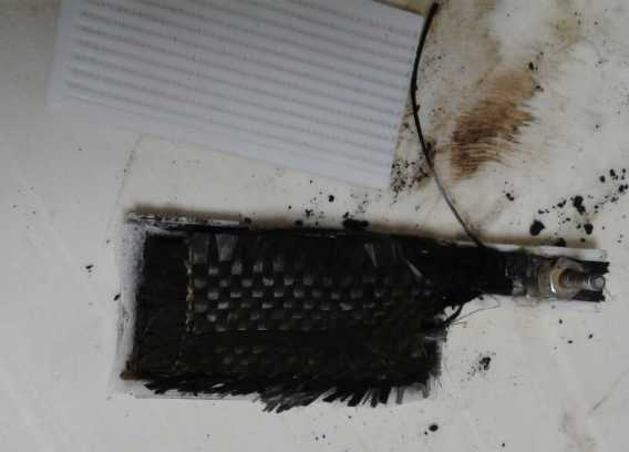
decided to check these out. I didn't get very far. I started 'munching'
the carbon fiber into the powder with the bar. But the PLA shell
started breaking up. It would seem PLA deteriorates in alkali, and then
falls apart entirely.
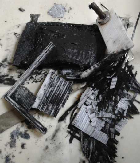 PLA plastic electrode shell, disintegrated in
alkaline environment.
PLA plastic electrode shell, disintegrated in
alkaline environment.
But the currents, shattered shell and all, went up to
around 170mA shorted (10 seconds) and it held 1.525 volts overnight.
That current was in the same neighborhood as my nickel manganate
attempts. I started to suspect the connection of the electrode material
to the carbon fiber current collector really was the bottleneck.
I tried a load test (after it had sat overnight) with 60
ohms. Voltage was soon down to 1.25. But there the drop slowed and it
ran for an hour and 20 minutes before it was down to 1.000 volts
(exactly), having delivered around a whopping 23 mA-Hours of electrons.
(I didn't add salt to the electrolyte, so it was weak KOH, pH 13. Some
salt(s) (or more KOH) probably would have improved the result
somewhat.) It recovered quickly (45 seconds) to 1.25 volts, then more
slowly (9 minutes) to 1.35 and 1.36 (13 minutes). It was still rising
slowly but I had things to do and put it on to recharge.
I would like to make a similar electrode and compact the
carbon fiber cloth into the middle of the mix for better contact, but
if I couldn't make a shell, that was going to be tricky. In fact it was
starting to hold up all the experimentation.
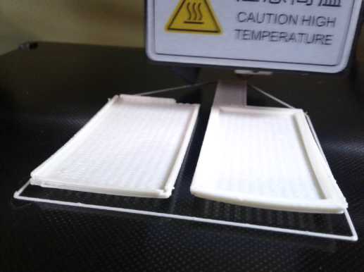
Printing An ABS Electrode Shell
Somehow I would have to get ABS shells to print out nicely
after all. As to that... Why on earth would the printer not set the bed
warm enough to make ABS stick to it in the setting for ABS? (Just one
more stupid piece of programming to sabotage good operation of an
otherwise fine product - see my diatribe on this subject last month
also under 'batteries'!) Now what do I do? I hadn't been able to get
the old printer to work again, and I hadn't been able to get it to
print "porous" well at any time. One number... why did they change it?
Maybe move the heat sensor away from the bed so it didn't think it was
at 80° yet? Too much disassembly and too uncertain. Was I going to
have to give up on the whole electrode shells idea because PLA didn't
work and the printer bed ABS temperature setting was wrong and not
changeable by the owner? The old printer let you enter any temperature.
Did I have to come up with a whole new plan because of that? All too
discouraging! Must be time to go eat ice cream, stack today's lumber
milled on the band mill (twelve 12 foot 1x6es) and do a sudoku.
I returned to the charge late at night with a web search.
Someone had made a plastic a 'tent' over the printer with
'greenhouse'-like construction, and heated the entire space with an
electric heater. He said he got great ABS prints. Someone else
mentioned some better materials than glass to print on, and an "ABS
juice" of ABS liquified in acetone.
 Someone else mentioned setting the I3 Mega bed hotter. Huh? I went back
to the printer and found another menu. (I should check these things out
better - but I only want to print, not learn how to use it!) The "ABS
setting" sets the bed to 80°c, but the other menu lets you set it
to any temperature. I set it to 105°C and tried printing a shell in
ABS. This time it printed the first two layers fine, but then the
corners lifted and the prints came loose. But the gcode had set the
extruder temperature down to PLA level. Perhaps it would print okay if
increased to ABS temperature? Anyway before I retired very late, I had
something that looked like a bottom for an ABS shell, with the porous
face. It could (surely) be done! But the next morning (11th) I redid
the file with ABS extruder temperature, and it was little better.
Someone else mentioned setting the I3 Mega bed hotter. Huh? I went back
to the printer and found another menu. (I should check these things out
better - but I only want to print, not learn how to use it!) The "ABS
setting" sets the bed to 80°c, but the other menu lets you set it
to any temperature. I set it to 105°C and tried printing a shell in
ABS. This time it printed the first two layers fine, but then the
corners lifted and the prints came loose. But the gcode had set the
extruder temperature down to PLA level. Perhaps it would print okay if
increased to ABS temperature? Anyway before I retired very late, I had
something that looked like a bottom for an ABS shell, with the porous
face. It could (surely) be done! But the next morning (11th) I redid
the file with ABS extruder temperature, and it was little better.
Someone on the web had mentioned that "layer fans" were
death for printing ABS. I thought of the fan slit blowing air onto the
work. Was that a "layer fan"? Probably. I stuck modeling clay over the
opening and tried again. It went a couple more layers before it curled
up and broke loose. Too bad it was blowing cold air instead of hot,
which would have reduced the shrinkage. Basically, this printer was
awful; it just didn't print ABS. (And at 230° extruder many of the
porous holes were filled in, even whole sections. It worked better at
220° or even 200.) Well, if the worst came to the worst, it printed
the porous faces now before the prints broke loose. I could always
print the faces and make the rest of the shell out of solid ABS sheets
for test electrodes. But what a pain!
I gave it one more try. I turned the bed down to 95°C
- the lowest ABS will stick to the glass - and the extruder down to
220°, hoping it would shrink less as it cooled. And I printed a
"skirt" at the bottom to help hold it down. All to no avail! The old
RepRap was no hell, but it printed ABS way better than that. Why, when
it was such a similar setup? But at least turning temperatures
down had restored the porosity: melted plastic hadn't smeared over the
tiny holes.
I looked on line and found "7 best printers for printing
ABS". They all had enclosures, "ovens" - the thing I hadn't found when
I was looking for a printer and bought the Anycubic I3 Mega. Most of
them weren't cheap. Perhaps if/when I have funding. Or perhaps I should
make an enclosure over the whole printer, like the fellow's
"greenhouse" on youtube?
There was one more thing to try. I took the hot air gun
and heated the curled pieces until they flattened. If I had it blowing
on the printer bed as the printer worked, the parts might stay hot and
soft and not warp, and so would print okay. The trick would be to mount
it somehow where it wouldn't interfere with the printing, and then to
find the right distance and angle to blow from: not too hot, not too
cool, across the pieces being printed. Luckily the pieces for test
electrode shells were pretty small.
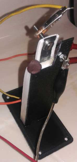
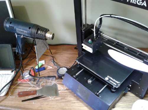 On 12th I made a stand to hold the heat gun so it could point at the
print bed. I printed a shell. It came out perfect - completely flat, no
warping. It seemed terribly wasteful blowing 750 watts of heat at the
printer for the duration, and I don't know how long everything
(including the heat gun) would last with this as a regular setup. I
would turn the heat down if it had more settings, or I would move it
farther from the printer if there was room on the table. But the only
casualty found on the first print was that the "warning, high
temperature" label by the print extruder curled up from the heat
of the hot air.
On 12th I made a stand to hold the heat gun so it could point at the
print bed. I printed a shell. It came out perfect - completely flat, no
warping. It seemed terribly wasteful blowing 750 watts of heat at the
printer for the duration, and I don't know how long everything
(including the heat gun) would last with this as a regular setup. I
would turn the heat down if it had more settings, or I would move it
farther from the printer if there was room on the table. But the only
casualty found on the first print was that the "warning, high
temperature" label by the print extruder curled up from the heat
of the hot air.
I noted that a hair dryer
is also 750 watts on 'low', but it blows much more air so it's not as
hot. But I tried it the next time and found it was totally inadequate.
The parts warped up the same as without heat.
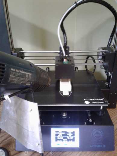
Printer printing ABS with a heat gun blowing hot air
on the piece. For a printed battery case I had to get
the hot air quite close. (I held it by hand for the whole
print the second time.) But then, yay! It printed the
ABS without warping it!
Experiment 2: Nickel NiOOH electrode
The pieces of NiOOH electrode from the dry cell worked at
pH 14 and had given good high currents. Now using a less than pH 14
electrolyte, they might not. Certainly a metallic current collector
would dissolve. The fine nickel mesh inside the pieces would also turn
to nickel oxide/oxyhydroxide, which would reduce the conductivity.
Well, how about trying the dry cell pieces, but in a plastic shell with
a carbon fiber current collector?
After getting the 3D printer to print a shell on the 12th
I tried this. I had intended to throw the electrode pieces into some
bleach to oxidize them in advance, but as usual I forgot one of the
several planned steps. So the cell started very uncharged. And it
didn't seem to hold a charge, even in weak KOH electrolyte. Yet it
wouldn't take charging current very fast.
Surely the low currents must be a result from the carbon
fiber cloth current collector - nothing wanted to charge fast or drive
a heavy load since I had started using it instead of metal. But hadn't
I measured the fibers as being very low resistance? I got out a meter
and found the truth: if there were just a few fibers, a single "strand"
of the cloth, resistances were in the tens of ohms. My memory was
faulty. It was doubtless useful, but not as good as I had thought, not
"under an ohm". Making the cloth thicker, perhaps two layers, might be
better. In fact, maybe a layer of electrode, a layer of cloth, then
more electrode... maybe 2 or 3 or 4 of cloth and 3 or 4 or 5 of
electrode material, all fairly thin layers.
And then there was Diesel Kleen to soften the graphite and
reform it with better conductivity. How well might that work?
And there was one other thing to try: Since the strands
going up to the top of the terminal had too high a resistance, and yet
only graphite could be used, I could connect a piece of graphite foil
or flex graphite go up to the terminal, extending far enough into the
electrode to make lots of good contact with the strands therein. That
should make for substantially better connection from the electrode
substance to the external circuit. And it would be easier than trying
to coerce the strands to bend into the channel running up the plastic
terminal strip.
But there was another factor. The NiOOH electrode pieces
were poor at first and had gradually improved even in the best cells
with metal and KOH. Now I measured them too, and found resistances like
a megohm or more, but some much lower. I attribute the lower
measurements to the enclosed fine nickel mesh. The Ni(OH)2 was long
since completely discharged, and discharged Ni(OH)2 has very high
resistance, probably explaining the megohms.
Now that I had an electrode shell that was snapped
together (if not very well) instead of glued, and wasn't
disintegrating, I removed it from the cell and soaked it in quite
concentrated bleach for half an hour. Then I put it back. (The sodium
hypochlorite bleach, NaClO, would convert to NaCl electrolyte salt once
the "O" was used up. Right? - I get less and less sure about such
things as I go along.)
It still didn't work very well. It started at just ~1.43
volts instead of 1.7-1.8 and even when charged didn't seem to hold a
charge. So far I liked the manganese better. Could I get nickel working
somehow? It seemed silly that it wasn't going well. Maybe I need to do
the jell on the "+" electrode. Or use the Sm2O3 additive to raise the
oxygen overvoltage. Or both.
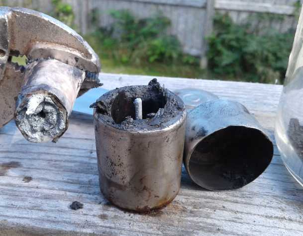
Extracting MnO2 from old dry cells
I had been puzzling over a good way to do this for the
longest time. Here is all this fine battery electrode substance freely
available, but solidly encased in tiny, tough steel cans. (or just a
zinc can in the cheapest 'standard' dry cells.) I had thought of
cutting them open with an angle grinder. But the potassium hydroxide
would be very bad to spray over things, and would blind if one got it
in one's eye(s). A power hacksaw, maybe? Still messy, and I don't have
one.
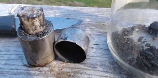 Suddenly on the 9th the answer came to me: a plumbers pipe cutter for
copper plumbing pipe! Sure enough, it sliced a "D" cell battery can in
two quite nicely, and there was no mess. (But somehow the old cell from
a box had KOH all over it and I was obliged to wash my hands repeatedly
and hold it with a pair of vicegrips. Or I could have put it in a
vice.) In fact the pipe cutter makes it easy enough I might find it
practical to open "C" and "AA" cells instead of only "D" cells. (Nope,
"AA" is harder, and for little substance. "C" maybe.) Next time I wore
nitrile "single use" gloves, and put the battery in a vice.
Suddenly on the 9th the answer came to me: a plumbers pipe cutter for
copper plumbing pipe! Sure enough, it sliced a "D" cell battery can in
two quite nicely, and there was no mess. (But somehow the old cell from
a box had KOH all over it and I was obliged to wash my hands repeatedly
and hold it with a pair of vicegrips. Or I could have put it in a
vice.) In fact the pipe cutter makes it easy enough I might find it
practical to open "C" and "AA" cells instead of only "D" cells. (Nope,
"AA" is harder, and for little substance. "C" maybe.) Next time I wore
nitrile "single use" gloves, and put the battery in a vice.
 I
pulled out and saved the "bags" of zinc electrode, too. I did more on a
couple of occasions because it just seemed more satisfying than
experiments and 3D printing that weren't going well.
I
pulled out and saved the "bags" of zinc electrode, too. I did more on a
couple of occasions because it just seemed more satisfying than
experiments and 3D printing that weren't going well.
I could also see automating the process and taking all the
recycled cells I can get as free material for battery production.
To anybody who does this:
wear safety glasses (or just glasses) and gloves. DON'T get it in your
eyes. Don't rub your eyes while working. Wash your hands after. Any
"slimy" or "soapy" feel means there's potassium hydroxide there, eating
into your skin and flesh. If you don't wash it off, it can do a lot of
tissue damage. (This, after all, is why I've been trying to find a less
hostile electrolyte.)
The hollow cylinder manganese dioxide electrodes were:
CAN: 32.92 mm OD; .33 mm thick metal
MnO2 Electrode:
5.7 mm thick,
52 mm tall
32.26 mm OD (32.92-.33-.33)
(and hence 20.86 mm ID.)
= 476 sq.mm (OD-ID area) * 52 mm (length)
= 24.7 cc of MnO2 (+graphite, + KOH, +H2O)
I was surprised to find the MnO2 outer electrode was only 5.7mm thick.
That's a very thick electrode, pretty much the maximum but not as I had
supposed "ridiculously" thick. It also explains why "D" cells are the
largest diameter made - any larger and the thickness would be
ridiculous.
The mass for two "D" cells was 141 grams. For the few flakes I lost,
I'll call it 78 grams per cell. If such cells are said to be 12-18
amp-hours, that suggests the MnO2 must supply 153-230 AH/Kg.
Theoretical total value is about 309 AH/Kg, so it's being pretty
decently utilized.
So the density of the MnO2 mix was 78g / 24.7cc = 3.16 g/cc. IIRC the
density of 'fluffy' nickel oxyhydroxide 'trode substance is only about
2.1 . (?)
This gives a figure to aim for when compacting a manganese electrode.
If it's very far under 3, it must be poorly compacted.
What do we know about Mn-Zn dry cells? The alkaline "D"
size will put out over 8 amps if shorted. That's with those thick
electrodes and... how much interface area? 52 mm tall *
(πD=π*20.86=about 65 mm circumference) = 34 sq.cm .
8 / 34 = 235 mA/sq.cm. Actually that's very impressive. If I can get
1/2 of that with carbon fiber current collectors, or maybe even 1/4,
I'll be happy.
The wetness of the cell seems much higher than that of
nickel-metal hydride. Since the cells don't recharge, they don't need
to worry about oxygen being blocked to the zinc side during charge.
This will allow them much longer life without drying out than
rechargeables. (That's why I don't want to make dry cells for mass
storage. Adding a bit of water every few years is better than having
them dry out.)
And we know they aren't very rechargeable. But is that
just because of the zinc dissolving (presumably solved with the agar)
or are there problems with the manganese side as well? A paper by
Polish researchers hints that Mn2O3 or Mn3O4 may not be electrically
conductive. I thought all oxides of manganese were conductive. That
would make for a non-reversible component of the reactions. They used
zinc sulfate electrolyte to get two electrons moving at once,
converting the MnO2 directly into Mn(OH)2 without creating the
intervening compounds above. These are real battery researchers, so
they're probably right. But I note that another electrolyte besides
sulfate for the two electron move would be potassium oxalate. Either
there's some problem with it I'm still unaware of, or they (more
probably?) never thought of it.
The discharge graphs in the Polish study also weren't very
flat. Voltage kind of meandered down gradually as the cell discharged.
That may perhaps excuse own my nickel-zinc tests for behaving that way.
My other take is that MnO2 needs an extra .45 volts or so
to charge to KMnO4. If Mn2O3 or Mn3O4 aren't a problem, then as long as
the charge voltage is kept under 1.9 volts per cell (max!), the
manganese side should be okay. Also, the dry cell electrodes aren't
jelled. A working jell should make them indefinitely(?) rechargeable.
And hopefully obviate the problems noted by the Polish team. That was
probably the next thing to try, to jell my electrodes, which didn't
seem to be working very well whether MnO2 or NiOOH.
Experiment #3: Jelled MnO2
The nickel oxyhydroxide electrode hadn't performed. The
nickel manganates electrodes hadn't performed. Manganese had at least
worked. The low currents in all of them were explained by the carbon
fiber current collector high resistances as well as probably the
connections between the electrode substances and the fibers.
One choice would be to go back to straight alkali
electrolyte, and use a nickel (or cupro-nickel or monel) current
collector. But first there were improvements that could be tried. They
might make the nickel work, or they might make the manganese work
better - even work well.
(13th) The MnO2 had seemed to charge up and hold a good charge the
first time, but after that it didn't charge as well and didn't stay
charged overnight. Perhaps it was time to try the jelled electrode
plan? Would it work at least as well at least once when jelled - and
then hopefully continue working every time thereafter - or was my Lemon
Fresh Sunlight dishsoap (having sulfonates like nafion membrane) a poor
choice of jell?
I took apart the non-performing NiOOH 'trode and cleaned
out the shell. I got a piece of graphite foil. It wasn't perfect
either. It seemed its internal resistance was pretty low, but surface
contact resistance was high. It got lower with (a) the more area of
metal in contact with the surface and (b) the higher the pressure was
between them. At first I was having trouble getting a reading under
2000 ohms with just meter probe points digging into it. Pressing down
hard on chunks of sheet metal set on top of it, I got it down to under
an ohm. That still seems pretty poor compared with any piece of metal.
I guess the answer is lots of carbon fiber in contact with it inside
the electrode (and some diesel kleen?), and a big fat washer bolting
the graphite foil solidly to the plastic at the top. Maybe a washer on
each side of the foil? I note that on standard dry cells, the metal
button piece is crimped pretty hard onto the graphite rod, for the same
reason.
"D" Cell Graphite Rod Experiment
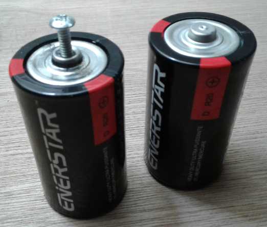 Perhaps this is a good place to mention my little experiment with
standard "D" cells. I bought a couple at the dollar store. My idea was
that if there was a metal rod inside the carbon rod, one might get
lower resistance and hence be able to draw more current from these
cells. The cells only weighed 78 grams - hardly 1/2 the weight of the
alkaline ones. I suspected they weren't even full - the "AA" cell in a
"D" package sort of thing. Anyway, they managed to put out about 5 amps
when shorted, which seemed very good.
Perhaps this is a good place to mention my little experiment with
standard "D" cells. I bought a couple at the dollar store. My idea was
that if there was a metal rod inside the carbon rod, one might get
lower resistance and hence be able to draw more current from these
cells. The cells only weighed 78 grams - hardly 1/2 the weight of the
alkaline ones. I suspected they weren't even full - the "AA" cell in a
"D" package sort of thing. Anyway, they managed to put out about 5 amps
when shorted, which seemed very good.
I drilled a hole into the end of the rod on one of them. I
was afraid of coming out the side of the rod so I didn't go very deep.
How to get good connection? I threaded it, and screwed in a bolt.
Instead of going through the whole rod or even a lot of it, it only
went in 5/8 of an inch or so. When shorted via my bolt, the current
was, if anything, just marginally lower than when shorted to the button
(they were presumably shorted together anyway), both still about 5
amps. I hadn't done any better than the crimped on button on top.
Would a full-length piece of copper protected by a thin
shell of graphite conduct better and give the cell more current
capacity? I don't think I answered that question.
New Electrode Compactor Punch and Die
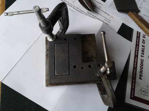 Another problem of course was that I wasn't compacting the powders the
way they should be. I had a good idea what the consistency should be
from scraping it out of the dry cells.
Another problem of course was that I wasn't compacting the powders the
way they should be. I had a good idea what the consistency should be
from scraping it out of the dry cells.
I hadn't found any of the old compactors except the edge
compactor, and I didn't want to do it that way. On the 14th I decided I
simply had to make a new compactor that I could put in the hydraulic
press. Need I say making a rectangular punch of 1/2 inch steel and a
matching square die cut into the inside of similar 1/2 inch steel was
tedious work, with drill press, angle grinder, jig saw and - mostly - a
file. On must of course cut the hole for the die a little undersize in
order that it not be oversize here and there. I couldn't think of a
magic tool to grind on the inside of a rather small rectangle, so it
was file, file, file, file until the punch would slide through freely.
And I should have found a bigger piece - I fear one thinner side may
bend out under pressure. (It was okay.) But I don't have a big
selection of steel scraps.
One thing that bothered me was, how to put in the graphite
foil strip? It would be hard to accommodate something sticking out of
the die when compressing the electrode substance. Either there would be
a big hole or the piece would be sheared off as the inside section was
pushed down. I decided to put a short strip of metal of the same cross
section in the die with the electrode during compaction, along one edge
to the corner. (Or along the entire length?) Then I could pluck out the
metal and replace it with the longer strip of graphite. That was the
best idea I could come up with offhand. But when I tried it the
currents weren't very satisfactory, and I started thinking of ways to
get better internal connections.
(15th) I had the thought that there was one way the foil strip could be
compacted into the electrode: instead of having it in the middle, have
it right at the bottom of the compactor with a slit in the bottom of
the compactor die . The material would be crushed down onto it but it
itself wouldn't move. And while it had to be at the bottom where it
exited, it was flexible enough that at least some electrode material
could be stuffed under it at the other end to somewhat center it in the
electrode.
In addition, I could center the terminal strip instead of
having it in a corner, and make it wider, maybe 1/2 inch. Apparently
improvements are to be had by degrees, not in some big jump with a
single change.
Sewing Carbon Fiber Cloth
The cloth seemed to fall apart quickly with handling. Each
'weave' of fibers at the edge would fall out, and then the next one. I
had to cut a new piece off the roll. Instead of a little piece I cut a
foot by a meter. One edge was sewn with some other thread at the
factory to keep it from unravelling. I decided to tape the other edges
and then try to sew them, so the thread would hold them together. The
taping went okay. The sewing was a nightmare. I must have spent half an
hour inserting the thread in the needle. It kept having problems and so
I had to do it several times. I had to use an LED close work light, a
strong magnifying glass, my best scissors (to cut the thread cleanly),
and two pairs of tweezers - one to insert a short end through the
needle and the other to pull it through before I lost my grip and it
slipped out again. I broke one needle and had to restart rows multiple
times, or start from the middle where it had fouled up. In several
places I put two rows side by side, so that when I cut it between the
two neither side would unravel. The final two little pieces were still
coming apart in the die as I added electrode material. Then after
pressing with 9 tonnes, the electrode still came apart readily at the
carbon fiber layers.
It may be a good technique, but I hope to have someone
else do it next time. Then again, I started thinking it might be better
just to let it come apart and sprinkle fibers in with the material in
the compactor. Or, there was the graphite foam instead of the cloth.
That should make for good connections throughout the electrode in 3
dimensions.
The Electrode
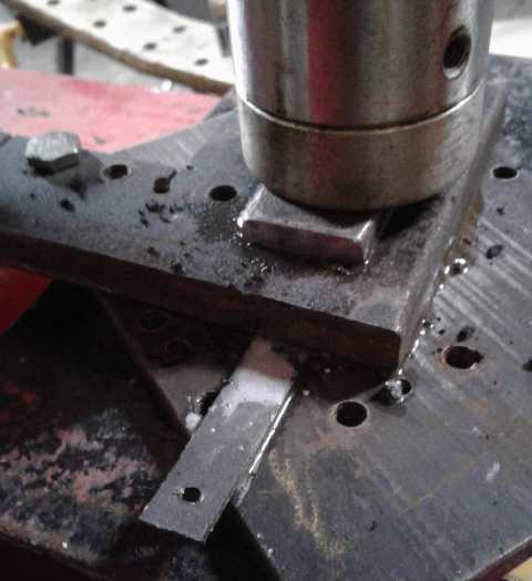 I compressed 30 grams of MnO2 material crumbs from dry cells with
Sunlight dishsoap. I made it into 3 layers with 2 layers of graphite
fiber cloth between them. But it was much too thick, maybe 1/4 inch. I
removed the top layer and the top layer of cloth, leaving maybe 20
grams of material and one piece of cloth. I put this with a graphite
foil stick into the shell, with the thin piece of PP cloth under it
wetted with more Sunlight.
I compressed 30 grams of MnO2 material crumbs from dry cells with
Sunlight dishsoap. I made it into 3 layers with 2 layers of graphite
fiber cloth between them. But it was much too thick, maybe 1/4 inch. I
removed the top layer and the top layer of cloth, leaving maybe 20
grams of material and one piece of cloth. I put this with a graphite
foil stick into the shell, with the thin piece of PP cloth under it
wetted with more Sunlight.
I dumped in some distilled water with whatever electrolyte
was already in the cell and the KOH already in the MnO2 (which had made
my fingers somewhat raw in the handling, as I didn't get it rinsed of
right away). KOH is nasty stuff and I hadn't thought much about it
being in the MnO2 from the dry cells as I filled the die.
The cell started at .621 volts, and in half an hour rose
by itself to .721. Then I put it on charge at 1.9 volts. Charging
current seemed to be well over double that of the previous electrode
with just carbon fiber, 40-50 mA instead of 10 to 20. The zinc negative
was frothing bubbles. No doubt it was highly discharged MnO2 (even
Mn(OH)2) from the old dry cells. I didn't want to add bleach so there
was no way to charge it except to have the already fully charged zinc
bubble hydrogen.
It put out only around 150 mA shorted, but it continued to
do so without fade for 10-20 seconds. After some hours charging it ran
a 60 ohm load at somewhat higher voltages than the previous MnO2
electrode, taking 6 minutes to drop under 1.30 volts and 20 to hit
1.25, at which point I halted it because it was late at night. No doubt
it would have run quite a long time, and it wasn't fully charged yet.
It bounced back quickly to about 1.47 volts.
I decided that was good enough for the 'battery challenge'
and turned my attention back to other things, including the idea of a
3D printed battery case and writing up the challenge application. I
also decided that the target market for the batteries would be bulk
electricity storage rather than electric cars, since the current
requirements are much lower with "during the day" charge and
"overnight" discharge or longer, rather than discharge in a two hour
drive and recharge in 20 minutes at some station. Maybe lithiums still
have a place in transport after all? (I could also do straight alkaline
nickel-zinc with the nickel metal current collectors. Those worked and
had much higher current. But the bulk storage market has less
competition and more need for lower cost.)
On the 15th I ran a load test. It ran for nearly 1/2 an
hour above 1.25 volts, but at the 60 and 70 minute marks, both readings
10 minutes apart both showed 1.169 volts, and in another 10 minutes it
was only down to 1.159, and 1.149 at the 90 minute mark. It became
apparent that the cell, for all its low currents, would run for several
hours before it was down to the standard cutoff point of .9 volts. (And
it still hadn't been entirely fully charged at the start.) It was
definitely a battery. I ended the test and it recovered almost
immediately to 1.36 volts, and went gradually up from there.
I took out a plastic spacer and put the original agared
zinc electrode into the cell on the other side of the MnO2 shell. Now
it had two zinc electrodes and double the interface area. It made no
apparent difference. The limiting factor seemed to be entirely the
electrical connections to the MnO2. Not surprisingly that was the
"chokepoint" that needed much improvement.
3D Printed Battery Cases (Déja Vue?)
3D printed battery cell
enclosure with "porous plastic" grille (2nd one)
I
started thinking about keeping things simple and having only one pair
of electrodes in a battery cell instead of "prismatic" cells. That
would eliminate the problems of connecting multiple electrodes together
inside and probably getting bad connections.
I thought about 3D printing thin cases as I had done in
early 2013 (TE News #60,61), and integrating the porous electrode
shells with the case. If the cells were really to be "zero maintenance"
except for occasionally adding water, I should be able to enclose them
and in the top only leave slits for the electrode tabs, and a tiny hole
for relieving pressure and for adding distilled water with a syringe or
eyedropper. (initially and if the cell got too dry after (presumably)
some years of use. ...or was badly overcharged?)
Instead of a double sided electrode shell, the whole cell
would simply have a divider, and one open face to insert everything
into. The cell would be lying down with the open face up during
installation. The MnO2 electrode would be set inside against the closed
face with its graphite foil terminal sticking through the 1/2 inch wide
rear-center slot in the top and the active face facing up. Then instead
of a whole electrode shell, just a piece of PP cloth and a porous plate
would be placed on top of it. Then the jelled zinc electrode would go
on that, with its terminal going out the front-corner slot. This would
let it be set in place gently without risk of scraping or scratching
the agar coating. These components would occupy the whole space right
up to the open face. Then a thin ABS sheet would be glued on to enclose
the cell. Finally some heat glue (or something) would seal the top
around the terminal slots, and a plug that would vent or pop out easily
would close the filler hole.
In a small variant to double the amp hours and current
capacity, one zinc electrode could go in first. Its painted terminal
tab would be bent around to come out the front-corner slot with the
other one. Then a porous face and PP cloth separator would go in, then
an MnO2 electrode, or perhaps two back to back, with the terminal tabs
together through a center-center slot), then another PP cloth and
porous grill. Finally the second zinc electrode would go in the same as
for the single cell, and both zinc tabs would come out the same slot.
(Don't forget to paint the zinc terminal tabs so they don't bubble
hydrogen and corrode.)
I don't see how this idea could be further expanded except
by having multiple graphite foil terminal tabs and having to connect
them together externally, since the graphite won't bend without
breaking and metal inside would corrode. I suppose two double graphite
terminal tabs (4 MnO2 electrodes) with a long bolt tying them together,
and with three zinc tabs bolted together in the front-corner slot could
make a passable "quad capacity prismatic" cell (Presumably only one
zinc sheet, perhaps more thickly plated, would be needed between the
two double faced MnO2s.)
Now a 3D printer that will print such cases without a hot
air gun blowing continually on it would be great. (Do I wait for
funding to buy a good one, or try again to get the old RepRapPro Mendel
working again? Why program in an "error condition" that doesn't reset
by cycling the power - or even by reloading the firmware? How can a
whole costly, complex product be made toast by a stupid software error
when there's nothing actually wrong with it?)
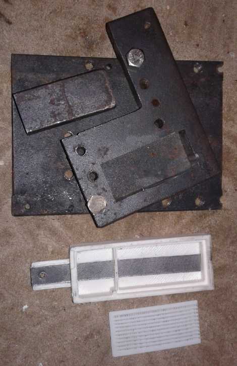 (16th)
I copied the 'latest' 3D print battery case design from 2013 and
changed the dimensions to suit the new 'test or sample size' electrode
punch & die size. Owing to starting by copying, the first cell
printed came out well and had most of the desired features. I decided
to just print a plastic plug for the filler hole (later), which I would
make smaller - that was necessary because there wasn't enough room on
top of this cell for the glass marble and the pieces to hold it in
place. I would trust the plug to leak at the edges or pop out if there
was much pressure. (In the event I stuck in a piece of modeling clay,
which apparently caused the case to rip a bit and leak when there was
pressure, in preference to popping out itself.)
(16th)
I copied the 'latest' 3D print battery case design from 2013 and
changed the dimensions to suit the new 'test or sample size' electrode
punch & die size. Owing to starting by copying, the first cell
printed came out well and had most of the desired features. I decided
to just print a plastic plug for the filler hole (later), which I would
make smaller - that was necessary because there wasn't enough room on
top of this cell for the glass marble and the pieces to hold it in
place. I would trust the plug to leak at the edges or pop out if there
was much pressure. (In the event I stuck in a piece of modeling clay,
which apparently caused the case to rip a bit and leak when there was
pressure, in preference to popping out itself.)
In spite of the hot air gun, the top of the electrode
started curling up off the bed. The print was much taller than the
shell, and the top was coming out of the hot air when the printer was
doing the bottom end. I picked up the gun and moved it around to the
front. I had to hold it there for the rest of the print. However, the
piece didn't come loose from the bed, and the more critically
dimensioned bottom 2/3 including the bottom corners didn't curl up.
Then I printed a porous sheet to fit inside. This time it
was just the sheet - not a front and a back with side walls. The cell
provided the enclosure for the MnO2 electrode - as well as the zinc one.
Lastly I cut a piece of black sheet ABS for the front
face. (case colors, + =white, - =black ...I could print with red ABS,
but it would be a lot of red!) After that it occurred to me that as the
back face was flat (assuming the corners don't lift in printing) and
just the right size, that if one also had a very good success ratio at
making batteries (like near 100% in production), one could stack the
cases and make "multi-cell" batteries by gluing the back of one cell
case to the front of the just filled cell. With Mn-Zn, four cells would
be 6 volts; eight for 12 volts. A 12 volt stack with single electrode
cells would be 4" thick/long. If nothing else, this would be lighter by
the amount of 7 front cover sheets, and would certainly stand up better
than 1/2" thick cells. But I digress.
Compactor Die Slit for Graphite Foil
Terminal Tab
I found a base for the compactor punch and die. It was
from another old compactor. It just so happened that two holes lined up
(several ways) if I set it on diagonally, and I could screw the base to
the die. That simplified things. Then, I wanted to mill a slit in the
compactor die for the terminal strip. The milling machine wouldn't run!
Out of a zillion tries, a couple of times it started for an instant,
then quit. One more machine that is just trouble instead of a help!
Finally I scratched a slit in the die with the angle grinder and filed
it out a bit. Ugh!
Some days later I demonstrated the milling machine to
someone, clicking it on and off. It spit once as it went off, but
mostly didn't run. He said "Looks like the switch. It's probably full
of crap."
Duh! The switch? Here I was thinking some piece of
software or sensor inside... because it does quit even when switched on
if it's overloaded, so I was thinking of that. (It stops until switched
off and then on again.) I've already had the box open and it's clean.
But the switch on the rheostat control would be a likely and simple
thing to check out. Or it may be the contacts in some relay that's
supposed to latch on, and open if it's overloaded. I could try locating
such a thing.
Later it was working - reliably for one particular session
- and I noticed it doesn't come on immediately when you click the
rheostat switch. It's probably not the switch.
MnO2 Electrode with Loose Carbon Fibers
Next I made an MnO2 electrode. Using the slit, it had a
12mm wide graphite foil terminal strip at the back-center to match the
printed case. This time instead of putting in a layer of carbon fiber
cloth, I started separating off individual strands with tweezers, and
then each strand into individual fibers, and putting or bending them
into the die. Then I would crumble a few bits of dry cell MnO2 to hold
them down. There were zillions of them, and it seemed like they were
everywhere, yet occupying very little of the electrode volume and
weighing almost nothing. It seemed to me it should be a very conductive
electrode. I filled the 1/2 inch thick die and dripped in a few drops
of the dishsoap (sulfonates jell). It already had the moisture from the
dry cell electrolyte, and liquid oozed out everywhere when I compacted
it. Carbon fibers stuck out the sides too. Those made it dicey for
putting it in without shorts to the other electrode. (Maybe the grill
should have sides on it after all, to sort of enclose the zinc
electrode?)
I pressed it to 9 tonnes. Since it was about 25.4 x 57.5,
14.61 sq.cm, that's 616 Kg/sq.cm - probably about right. It came out
about 5mm thick, about 20 grams of MnO2 material. (That should be 3 to
4.5 amp-hours. Good luck on that with my usual results! I did my best,
but I'd be ecstatic if it had 1 amp-hour, and if it had any sort of
decent current drive.) Notwithstanding that the compactor punch fit
loosely into the printed cell's space, the electrode was just a bit too
big and folded in the middle when I tried to set it in place. (Maybe it
swelled a bit after compaction?, and probably was more fragile by being
so soaked?) I manage to crunch it down anyway. Note to self: add 1mm
width and 2mm length to the case dimensions for future prints.
Then I put in a piece of the thin PP cloth and the
separator grill, and tried to push stray carbon fibers down underneath.
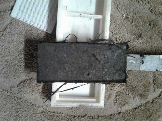 Electrode with foil 'tab' under and carbon
fiber cloth in it.
Electrode with foil 'tab' under and carbon
fiber cloth in it.
This fit in the bottom compartment of the 3D printed cell.
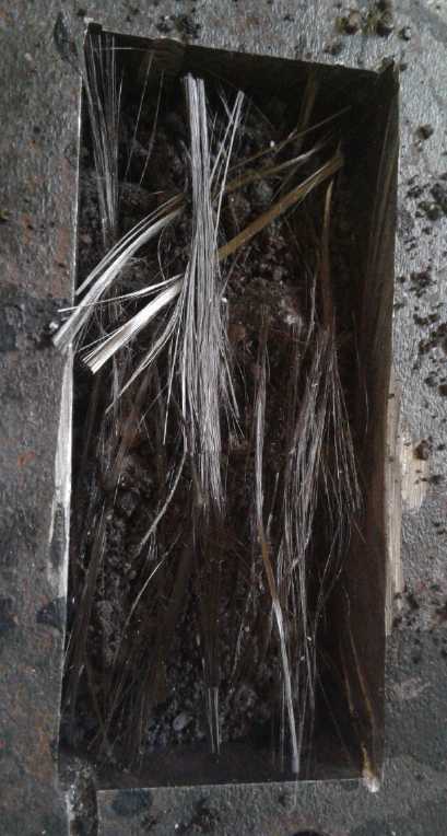 Making electrode with individual separated
carbon/graphite fibers.
Making electrode with individual separated
carbon/graphite fibers.
This can "spider web" connect across 'long' distances in the
electrode without the fibers occupying much space themselves.
Painted Zinc Electrode
Next I cut out a new zinc electrode, which it turned out
had to be a couple of millimeters narrower than the existing ones, and
with a longer terminal tab. After etching it clean with hydrochloric
acid, I spray painted the back side and up the terminal tab on both
sides with red polyurethane. Only one face would be across from the
plus 'trode so there was little point electroplating the back, and if
the agar didn't go all the way up the terminal tab, the zinc tab would
still be protected from hydrogen bubbles by the paint. The painted
sheet weighed 3.4 grams before plating and 5.1 after, so the plating
was 1.7 g. At 820 mAH/g, that's a theoretical 1.4 amp-hours. Adding in
the zinc sheet surely we must pass 1.5 AH. since it was also about 59 x
29 mm, or 17 sq.cm, that's about 88 mAH/sq.cm. Again I'll believe it's
actually anything like that much when I see it. But somehow these sorts
of figures seem to work for everybody else! It must boil down to
manufacturing techniques?
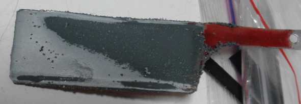 (This is actually the 2nd one, which I took a
picture of to show the crappy
(This is actually the 2nd one, which I took a
picture of to show the crappy
plating, which came from thin paint spray getting around under the
piece.
Metal has to be clean to electroplate it.)
I would note that some of the paint got scraped off the
tab and the back on the plastic supports in the electroplating tank. I
don't think I've had decent spray paint since I was making my sawmill
in 1996. IIRC it was about that time they outlawed some spray paint
solvents, and I don't think any have worked well since. They used to
dry in seconds, too. Now one is very lucky if they dry at all.
Sometimes they're still tacky if left by a hot woodstove all day. (I
noticed this was still a little tacky when I picked it up off the top
of the woodstove, albeit it was only warm, after leaving it on there
maybe an hour.)
(18th) I painted the osmium film onto the fuzzy front face. Then I went
out and bought a very small pan I could heat on my new lab heater &
magnetic stirrer. I put in some of the agar jell from the fridge
(egads, it's getting spots of mould on it!) and added about the same
amount of water. (It was too thick.) Then I left it to heat up.
Sometime later it still had big lumps of jell. I stirred it, and then
painted some onto the separator grille. That seemed like a really good
idea: even if there was a break in the agar on the zinc electrode, zinc
ions couldn't get through a jelled grille to the other electrode. Then
I painted the electrode too.
Cell Assembly
I had already put in everything else. Now I put the jelled
zinc electrode on top of the jelled separator sheet, and folded the
edges of protruding polypropylene cloth over the zinc. Note to self:
another millimeter or two depth would make it easier.
Next I took the sheet of black ABS and dripped some
methylene chloride around the edges, and stuck them together. There
seemed to be sections that weren't glued down, and I went over these as
necessary until it looked like all the edges were sealed.
Then I plugged in a heat glue gun and pasted heat glue
around the slots where the terminals came out. (Hopefully the "+" side
is well sealed, because the bolt on the last one rusted from positively
charged electrolyte getting up there.)
The complete cell, with no liquid, weighed 53 grams.
I looked at the 1/2" deep cell. It stood up fine -- if not bumped and
with no wires attached. I found an ABS box lid and glued the cell
upright onto it. That should help stop it from tipping over.
Then I used an eyedropper and put in just 4cc of
electrolyte, which was of the ratio 100cc H2O, 20 g KOH, 20 g KCl. With
that much I could see the top reservoir starting to flood. It was over
1.1 volts to start and I shorted it for a moment: 180mA. I put it on
1.8 V charge, and it started out drawing 100 mA.
Inevitably, for all my trouble, a pool of liquid soon
surrounded the cell. Why is it so hard to make one that doesn't leak?
At least with this one there was only one seam. (Or could it be leaking
through the 3D printed walls? That's an even worse thought!) A
flashlight showed that it only seemed to be wet at the seem - and of
course at the bottom: where I had glued it down to the support - now
the hardest place to get at to fix. (But not all seams are as they
seem... the bottom plate snapped off readily.)
But I left it running a while, even if it might become a
bit of a dry cell. After an hour or so charge was down to 70 mA, it
stayed above 1.4 volts, and it put out over 1/4 amp for 10 seconds if
shorted. That's at least some improvement over the previous, but I
can't help but think it could and should be much better. If it wouldn't
give the 3 or 4 amps of the nickel oxides electrodes with a metal
current collector, surely it could give an amp or more. More carbon
fibers? Fatter graphite foil? Diesel Kleen or toluene? More or less
compaction of the MnO2 mix? ...Or go back to another idea: graphite
impregnated conductive paint around a copper strip current conductor,
instead of the graphite strip. Perhaps that would up the currents?
I came back to it later and
inspected the seam under a good light with a strong magnifier. There
was nothing that looked like a leak. I dripped some methylene chloride
around the seam and smeared it with my fingers. But I wasn't satisfied.
Then I thought to get a scrap ABS bead the 3D printer had done, wet the
seam with m.c. and smear it in. I put the cell back and added another 3
cc of electrolyte. This time no puddles formed around the cell. I
checked the pH. It was 14 instead of 13. This puzzled me for a bit,
then I remembered that the MnO2 I used from the dry cells already had a
lot of potassium hydroxide in it. I shouldn't have added more in the
electrolyte. Just water and potassium chloride salt, and then checked
the pH. (and any other salt I wanted to try - namely K2C2O4.)
The cell continued to charge toward 1.6 volts at about 50
mA. That seemed somewhat higher than previous cells, and the charge
voltage was 1.8 instead of 1.9. When shorted it continued to put out
just over 1/4 amp, with little fade over 10 seconds.
I could have let it charge longer - it wasn't full yet.
But it was getting late, and as usual trying to fit in more than there
was time for I decided to run a load test. I started it at 10:30 PM
PDT, with the cell at about 1.58 volts. With a 50 ohm load it quickly
went under 1.4, but there it leveled out and only dropped slowly. It
was soon evident that it could run for hours. That was good since it
certainly wasn't much current! After 2 hours it was still at 1.219
volts and dropping less than a millivolt per minute. I kept it on to
the 3 hour mark at 1.172 volts, at which point it had delivered about
72 mAH. Extrapolating, it might run for over 3 more hours before it was
down to 1.0 volts, in which case it would have put out around 150
milliamp-hours, and maybe 200 by the time it was down to .9 volts. As I
expected, an amp-hour seemed out of the question. But it was definitely
a real, working battery... if it would cycle at least a few times
without degrading. And the old Ni-MH "D" cell nickel electrodes had
improved with cycling. Might it be that the MnO2 ones would too, or
were they a fixed quantity once made?
It only held 1.44 volts overnight, but the next day (19th)
short circuit current had risen to 300mA. I dropped the charge voltage
to 1.7 and it still was drawing around 30mA, down from 50 at 1.8 volts.
On the 20th I found it had held 1.46 volts for 17-1/2
hours. I did a small load test: 10 ohms. With the 'heavy' load it
wasn't much above a volt to start with. I ran it for 1/2 hour at which
point it was down to .9 volts, losing around 3 or 4 mV/minute, having
delivered ~38 mA-hours. I'm sure it could have run far longer if I
wanted to run it down .8 volt or lower, but I just didn't want to spend
the time. It recovered in a couple of hours to 1.39 volts, when I put
it back on charge.
I'm not sure why alkaline dry cells seem to be around 1.59
volts or so when fully charged while mine is dropping below 1.5. OTOH,
mine was improving with cycling.
(20th) I ran a 20 ohm load test. It ran for 2 hours 15 minutes,
delivering around 111 amp-hours. The final voltage read .952V, but
checking right on the graphite foil tab it was .989V, the difference
being from the resistance of the connection from the graphite foil to
the metal. (Solution to that problem next below.) Again it could have
run longer. Considering it was a 2-1/2 times heavier load than the
previous recorded test (50 ohm), I'd have to say the cell was improving
with cycling. And short circuit current was up further to 330 mA. Even
after the discharge, and then some recovery time, it still put out 280
mA. Being discharged to a volt, the cell rose in 30 seconds to 1.20 V
and overnight to 1.424 V - good recovery. (21st) After being recharged
short circuit current started at 390mA and faded to 360 after 10
seconds. Other than the high contact resistance I was well pleased.
That night the cell held over 1.5 volts for over 12 hours.
Yay! I figure the cells just need some charging and discharging to
"break in" or "form" until they're working at their optimum.
But just I was figuring it as a complete success, on the
22nd it seemed to have deteriorated, and it was even worse on the 23rd.
Another cell mysteriously losing charge? But I figured out why. The
cell had no water visible, so I added 1 cc. Soon after, another. There
was liquid under the cell. Had I spilled it? Aha! The cell was leaking,
and drying out inside. Well, that would explain the performance loss. I
was glad it didn't look like some mysterious problem with the chemistry!
One lousy seam! Can't I make a cell that doesn't
leak - and stays not leaking?!? Maybe I had better 3D print thicker
walls, just to give them more glue surface? The walls are 3 mm thick at
the seam. I guess I'll make the next cell fatter, with 4 mm walls.
Sigh! (Later I found the 3D printed cases really did seep liquid right
through the walls. It wasn't leaking at the seam.)
A Better MnO2 Current Collector?: Conductive Graphite Painted Copper
Fingers
(20th, Slightly out of chronology.) It had seemed in testing the
graphite foil with an ohmmeter that the more contact area there was,
and the harder metal was pressed against the graphite surface, the
lower the resistance reading was, and this was typical of graphite. I
put a 10 ohm load on the cell, and in 20 minutes the voltage was down
to about .90 volts. What would happen if I connected another piece of
wire to the "+" connection alligator clips, and then touched the other
end to a different point on the foil tab where it came out of the
battery, in parallel with the connection supposedly already made? I did
this and the voltage of the battery under load went up by 10 to 50
millivolts, depending on how hard I gouged it in. Then (even easier) I
took the voltmeter probe off the "+" aligator clips and touched it
direct to the foil tab. The actual battery voltage at the tab was at
least 100 mV higher than on the wires clamped right onto it! That made
the connection to be about an ohm - the very value I couldn't get much
under with the ohmmeter. To tighten the clamp would risk munching the
foil or breaking the 3D printed plastic backing.
There could be no doubt that the connection of the metal
to the graphite was the chief factor limiting current in the cell.
Perhaps a "star" washer would gouge into the graphite more and get a
better connection? I located one and put it on. It wasn't much
different. It had sharp points but I suppose less surface area than a
flat washer. Somehow these seemed to cancel.
Then I connected one side of the ampmeter to the minus,
and gouged the plus side into the graphite foil. For the first time it
gave 400mA of short circuit current - another slight improvement. So it
would seem the cell has more in it than it's letting on. Much of its
"internal resistance" is actually external. What I wrote below seems
like a better idea. (22nd) That gouging at one point might be better
gave me one further idea: I scratched the entire surface in the bolt
and washer area with a knife. Perhaps a freshly exposed surface would
have lower resistance? There was no notable change.
(19th) For next time... For positrode current collectors I had thought
again of the conductive paint on copper. With that the metal terminal
post at the top would make excellent connection to the connected wire,
which being a single point connection to graphite was obviously the
biggest inhibitor of good current flow; the "choke point". just as it
is in 'standard' dry cells, which is why they ("D" cell) only put out
around 2 amps where the alkaline version with metal connections puts
out 7 or 8.
First I thought of a simple sheet of copper, 12mm wide,
similar to the graphite foil. But I also thought about how the
slightest scratch in the paint would result in the eventual oxidizing
away of the whole thing.
What if the 12mm wide copper was split into 3 thinner
sections where it was inside the electrode? Well, then it would take
longer for the scratched leg to dissolve away and eat the other two
legs.
Better, make it about 9mm wide and split it just inside
the cell, above the level of the electrolyte, into 3 or 4 sections. Or
maybe even above where it entered the cell. Then if one leg rotted, it
would disconnect from the others. And if one twisted the copper
sections sideways inside the electrode, there would be twice as much
surface area in contact with the electrode substance. At first that
sounded like a workable plan. But during compaction paint was likely to
be scraped off as electrode substance was pushed past the vertical
copper faces.
Then I thought of the copper foil. It was too flimsy to
twist - if on edge it would fold or crumple during compaction. But it
didn't seem like twisting it was a good idea anyway. One could still do
the split into 3 or 4 pieces up at the top of the case. Furthermore,
the foil was so thin it would hardly take anything away from the
electrode substance's volume, leaving max amp-hours. And there would
hardly be any substance grinding over the very thin edges to scrape the
paint off. Now it started to sound like a real plan!
There was one further possibility with foil: one could put
one split-up sheet at the bottom of the compactor die, then some
electrode substance, then another slit piece of copper foil, then more
electrode substance. That would make 6, 7 or 8 "fingers" of copper in
the compacted electrode, well distributed horizontally and vertically
so as to maximize conductivity to all parts of it, but all coming out
the same slit through the top of the case. The one on the bottom would
contact on both the top and bottom faces. And it would be enough
fingers that if one or even two did dissolve they would hardly be
missed. In thick electrodes, even a third foil layer might be tried out
to see if it makes it better.
A final thought was that the split into fingers should
definitely be on the outside of the cell: if one finger dissolved but
the paint was still there, electrolyte would soak up inside the paint
and attack the other fingers. The paint, then, should end before the
top of each finger, and outside the cell. (One might even just
make individual thin painted copper fingers, and tie them all together
somehow at the terminal post - maybe with some sort of clamp. But at
this point we are probably getting into what's most convenient for
manufacturing rather than design fundamentals.) Or maybe instead of
foil, just conductive painted strands of copper wire? Say, that appeals
to me! No cutting sheets into thin pieces. And the more tiny strands,
the merrier!
There was one more point to this: unlike the graphite foil, the copper
could be bent around inside the top area of the cell to connect
multiple "prismatic" plates together, which would then come out at a
single terminal point. (And the paint in the fluid space above the
electrodes didn't have to be conductive.) I could make big cells with
as many enclosed electrodes as desired.
Much as I would like to verify that this will make the
excellent high current cell I'm certain it will, I had had enough of
making battery cells for a while after doing it all summer. I needed to
mill lumber (the spruce log is rotting - it can't sit out there for a
third winter!) and I want to put the model ground effect vehicle
together. Not to mention that I had to do the best I could at writing
up the application for the battery challenge itself.
So for now I just cut a piece of copper foil to illustrate
the basic idea. (The conductive graphite paint is around somewhere.)
The thin copper "squids" weighed only around a gram each - trivial!
It seemed to me this would have to be about the most
electrically conductive positive electrode one possibly could make
using electrolyte that required contact only with carbon/graphite and
no exposed metal. The dry cells with the carbon rod surely are crap in
comparison.
 (22nd)
My plan to leave off of batteries didn't hold very long. I did get some
wood milling done. In the evening I thought I would see what bare wire
I had for the wire idea. Copper wire is almost never bare. It's always
intended to conduct electricity where it's wanted, not to whatever the
wire touches anywhere along its length. But then there's stranded wire.
All the bare strands are enclosed in one insulator. At first I was
thinking of heavy electrical wires. But I went first into my
electronics lab. In the drawer was a big plastic bag of short, stranded
hook-up wires, about #24 AWG. I stripped the insulation off of one. It
had 6 very fine tinned strands. I cut it to the 110 mm size for
reaching from the bottom of an electrode to the electrode terminal in
the test cells, and did three more like it - in all, 24 strands. I used
a comb to somewhat straighten them out, after soldering the tops
together into a 'hook' for the terminal bolt. I put it in the compactor
to have a look. Then I spread them out inside it. It looked like just
what was wanted. With so many thin conductors everywhere I'm not sure
the carbon fiber will even be needed. And if one or two leak and
oxidize, they'd hardly be missed.
(22nd)
My plan to leave off of batteries didn't hold very long. I did get some
wood milling done. In the evening I thought I would see what bare wire
I had for the wire idea. Copper wire is almost never bare. It's always
intended to conduct electricity where it's wanted, not to whatever the
wire touches anywhere along its length. But then there's stranded wire.
All the bare strands are enclosed in one insulator. At first I was
thinking of heavy electrical wires. But I went first into my
electronics lab. In the drawer was a big plastic bag of short, stranded
hook-up wires, about #24 AWG. I stripped the insulation off of one. It
had 6 very fine tinned strands. I cut it to the 110 mm size for
reaching from the bottom of an electrode to the electrode terminal in
the test cells, and did three more like it - in all, 24 strands. I used
a comb to somewhat straighten them out, after soldering the tops
together into a 'hook' for the terminal bolt. I put it in the compactor
to have a look. Then I spread them out inside it. It looked like just
what was wanted. With so many thin conductors everywhere I'm not sure
the carbon fiber will even be needed. And if one or two leak and
oxidize, they'd hardly be missed.
Then I found the conductive paint. (unlabeled, ugh!, but
when I opened a little ointment jar that was light enough to have been
empty, it was obvious the black gooey stuff in the bottom was it.) I
looked it up in TE News #126: yellow polyurethane paint with conductive
carbon black. I thinned it down somewhat, and painted it on with a very
small brush. Then I combed it again and the paint seemed to have spread
everywhere. (It was a bit hard to tell: light shining off wet black
paint looks about the same as light shining off bare metal.)
Conductive painted copper 'fingers' and wire strands
 But the wires were still rather tangled together. When the paint was
dry, separating them made lots of bare spots. It would seem to do it
well the strands would have to be held separated for painting, all in a
parallel row not touching each other. For this one I just went over the
bare looking spots again with the still-wet brush.
But the wires were still rather tangled together. When the paint was
dry, separating them made lots of bare spots. It would seem to do it
well the strands would have to be held separated for painting, all in a
parallel row not touching each other. For this one I just went over the
bare looking spots again with the still-wet brush.
Then I did the copper foil 'squid' as well.
(23rd) I had thought it might be better to dip the wires in the paint
rather than brush the paint on. But I didn't want to make a great big
batch of the paint. As I painted the copper fingers it occurred to me
that with such long thin fingers only a tall dip was needed, not a big
one. I got one of my smallest test tubes that came from the kid's
chemistry set I was once given. The little bit in the jar filled it
right up. I dipped each wire and each finger in it, and then put a
rubber stopper on it.
The wires came out blobby but okay. Once dry the foil
fingers were either bare at edges or the paint was so thin as to be
transparent. They needed another dip.
I was astonished to find the test tube over 1/2 empty. Had
I used so much, or did it somehow evaporate through the rubber stopper?
Well, droplets of paint had certainly gotten everywhere. And only a
tiny bit more was needed to fill it to the brim again. I guess the test
tube really is that tiny!
It's a Product!
(19th) I decided I had my battery, enough of a demo product to go with
for the Charge the Future Challenge. All sorts of adjustments
to current collectors, electrolyte, jells and electrode mixes could
follow, but this one worked. 12 years of development and all I had done
was jell the electrodes of common manganese oxide-zinc cells? But that
simplistic assessment downplays the many little things and techniques
I've found and done over those years that are contributing to the final
product. And I may still make those manganese-manganese or
nickel-manganese 2.4 volt cells! Nobody else knows how to make those
except by reading Turquoise Energy News.
Cell with Graphite Coated Copper Current Collector
Deciding I was far enough along was great for a day or
two. I got some wood milled and a bit done on the ground effect
vehicle. But having come up with the fine graphite coated wires for the
positive electrode seemed to give the potential for much improved
current flow, and once again, that would be improved confidence for the
application. And the leaks in the working cell ate holes in my
confidence too. So I decided to do a new cell before submitting the
application after all. (Admittedly time would be running short for
testing it well.)
Cell Case - 3D Printing ABS
The next step was a case. I made the walls a millimeter
thicker for more surface area to 'glue' - at some point I need to be
able to make cells that don't leak! As I held the heat gun blowing on
the work to keep it from curling up while printing, I thought of one
person on youtube who had built a "greenhouse" to put over his 3D
printer (which was similar or the same as mine) for printing ABS with
good results. I think rather than buying a more costly printer - or
even several of them for production - I will do likewise. Perhaps an
enclosure whose whole front opens, with two or more printers inside.
The case came out well - no distorted corners or ends.
Plus Electrode with Graphite Painted Wires Current Collector
(25th) Looking ahead, with custom 3D printed cases and zinc coming in
rolls, I suppose the only thing keeping me from making larger cells
besides designing them - for example with electrodes the width of the
zinc strips and any suitable height to match that - is the lack of a
compactor punch and die of that size, and the lack of a press that
would sufficiently compact such a large area. (Let's see... at
600 Kg/sq.cm, 6 by 8 cm = 48 sq.cm; * 600 = 28800 or 29
megagrams/tonnes.) And the trouble with such a heavy press is that it
would tend to bend steel. The sides of the compactor might gradually
bulge out, or the die might warp.
Since the electrode material once compacted will stay
compacted, a technique that might be employed to reduce the force would
be to compact one end, then the other end, and then the middle, each at
just 10 tonnes. The briquette would compact diagonally for the first
two, making something of two wedge shapes, and the third one in the
middle would finish flattening it. That lesser force would be much
easier on equipment. Or to put it another way, would require less
costly equipment and a simpler punch and die. Presumably the extra two
squeezes wouldn't add much to the time with a pneumatic-hydraulic jack,
especially if the process was automated. (The compactor on a little
track would be moved to each exact location under the press, then the
press would be activated and then retracted.)
With the many steps to making a battery, automating most
of them would make for real production speeds, even if each step didn't
seem that fast. This will probably be the greatest production challenge.
The wires were now jumbled through the die. I added a bit
of MnO2 mix, then got some short bits of carbon fiber cloth. I pulled
out a couple of strands and started spreading them out into individual
fibers, which I placed into the mold. It's amazing how a few tiny
fibers can spread out to fill a space but in fact occupying virtually
no volume within. akin to a spider web. Then I added a little more mix
and then another layer of fibers. Considering a dry cell has just the
graphite powder for conductivity, while this one is also criss-crossed
everywhere (really in 3 dimensions) by tiny conductive strands (not to
mention all the conductive painted wires), touching each other here and
there, this cell should have way more current capacity for its
size.
I went a little thinner this time, using only 15 grams of
old dry cell manganese-graphite mix instead of 20. Apparently the
storage was limited by the zinc side rather than the MnO2, so more was
just a waste. But that only seemed to fill the die 1/2 way instead of
full, and I added another 3-5 grams to cover carbon fibers that were
still on top (layer 3). I guess there must have been more than 20 grams
in the first two, because they had filled the die. It compacted down to
about 3 mm thick.
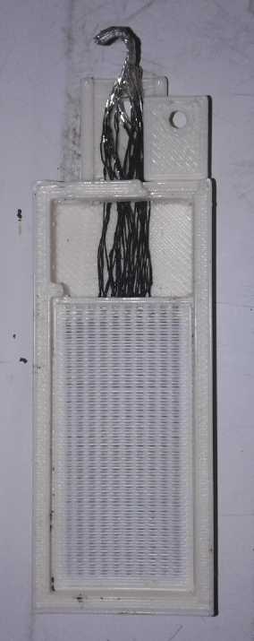 MnO2 'trode with graphite coated copper wires,
carbon fibers.
MnO2 'trode with graphite coated copper wires,
carbon fibers.
Right: in cell with 'porous' separator placed on top.
I noticed a couple of little bare spots on the fine wires.
Well, those two wouldn't last! I stuffed the top end through the
openings in the case and put the electrode in. I noticed more bare
spots on some of the wires above the electrode but still inside the
case. They were accessible and would have time to dry, so I got out the
conductive paint and went over them. And in the electrode compacting,
what were the chances that none of that paint had got scraped off the
wires? I must say my level of confidence in conductive painting metal
surfaces for an electrode is waning.
Copper Foil Strip
(26th) If this cell deteriorates because the fine wires
are exposed and oxidizing - and at this point I would be almost
surprised if it didn't - I may have to try a different tack. I could
lay down a flat conductive painted copper foil current collector at the
bottom of the cell and then set the compacted electrode brick on top of
it. That way the painted copper wouldn't have to go through the
compacting process. It also wouldn't make as good a connection. But it
might be good enough, and it had a better chance of working.
In fact, I decided to do that even with this cell. I had
the copper 'fingers' too, but in spite of a couple of brushings and a
couple of dippings in the paint, they too had bare spots. Instead I
decided to cut a single 12mm wide strip of copper foil, scour and sand
it thoroughly to get it clean and give the surface some texture, and
hope it would hold the conductive paint better. Then I would work the
electrode loose, slip the painted strip in underneath, and then put it
all back.
First I checked my paint dip test tube. It was less than
11 mm inside diameter. Fine, I would do the strip 10 mm then.
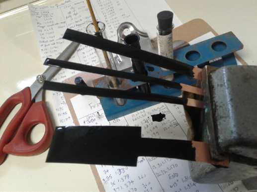 I did a 10mm strip and two 6mm. While they were drying, it occurred to
me that maybe I should be doing the full size of the electrode, with
the strip coming out the top for the terminal. Not only would that give
conductivity across the entire electrode, but the electrode shouldn't
be munching down on the edge of the copper anywhere, which was where
the paint was most vulnerable to being chipped away. In fact, if the
copper could somehow extend just a bit past the electrode brick on all
sides, that would inspire me with the most confidence that the paint
wouldn't get scratched. How? Maybe make a little plastic frame to go
around the electrode? Well, that would take an adjusted case design.
The case was already printed.
I did a 10mm strip and two 6mm. While they were drying, it occurred to
me that maybe I should be doing the full size of the electrode, with
the strip coming out the top for the terminal. Not only would that give
conductivity across the entire electrode, but the electrode shouldn't
be munching down on the edge of the copper anywhere, which was where
the paint was most vulnerable to being chipped away. In fact, if the
copper could somehow extend just a bit past the electrode brick on all
sides, that would inspire me with the most confidence that the paint
wouldn't get scratched. How? Maybe make a little plastic frame to go
around the electrode? Well, that would take an adjusted case design.
The case was already printed.
For now it seemed worth while to make a painted copper
foil piece the whole size of the electrode. But it had to fit in easily
so as not to scrape the paint on insertion, and the electrode wires
couldn't scrape it when putting it back in. I decided that meant
cutting off those suspect wires. or just making a new electrode that
didn't have any.
And a nagging question... Should the paint be thick or
thin? I finally decided that a good thick coat would be best protected.
In fact, going back to thick conductive epoxy (epoxy with graphite,
which I tried out many moons ago) might be better - epoxy was strong
and bonded to itself, which would encase the copper better. For the
moment, using the polyurethane paint was easier than mixing a batch of
epoxy, which would soon set. But I suspect epoxy would be much the
better for production - if it didn't make for too high a resistance.
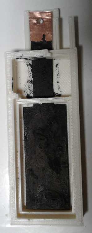 So! The polyurethane proved not to be so easy after all. I would put on
a thick coating which would dry very thin, and leave exposed copper
bits. I had to go over these spots several times until there was no
more exposed copper visible.
So! The polyurethane proved not to be so easy after all. I would put on
a thick coating which would dry very thin, and leave exposed copper
bits. I had to go over these spots several times until there was no
more exposed copper visible.
I then started thinking that perhaps to seal it better, a
sheet of graphite foil or flexible graphite should be pasted onto both
sides of the copper with the conductive paint as glue.
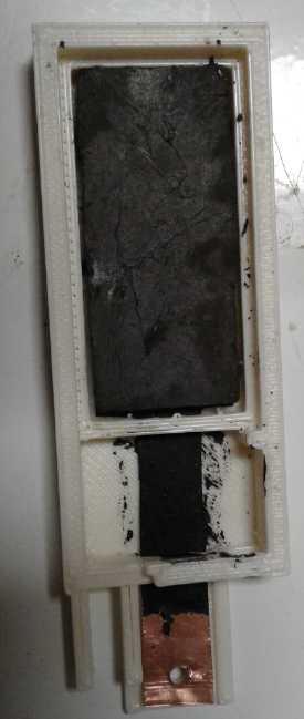 1. The painted copper foil.
2. With electrode brick on top (and for some reason shown "upside down")
1. The painted copper foil.
2. With electrode brick on top (and for some reason shown "upside down")
On the 30th I looked on the web and found a few different
ideas. One was using my calcium oxide layer plus something called
pozzolan, plus graphite, to make something of the consistency of a
carbon rod around the copper. That might be possible. Another was
mixing clay with graphite. I don't see how that could work, but perhaps
I'm limiting my imagination and there are more ways to do it that I've
thought of.
One thought is that while an entire copper current
conductor will quickly turn to copper oxide in most any positive
electrode, copper oxide is a fairly low resistance semiconductor. If it
could amalgamate with calcium hydroxide - or something - to form a
non-permeable skin that would protect the copper inside, similar to
aluminum and titanium, and to nickel in positive electrodes at pH 14,
perhaps that could protect it and eliminate the need for a graphitic
surface in the current collector entirely?
I looked up "calcium copper oxide" on the web and didn't
come up with much useful info. But it does exist, in several
variations. ("... Two intermediate crystalline phases, namely Ca2CuO3
and Ca3Cu7O10, form. ...")
Most of the search hits were for a "high temperature
superconductor", "bismuth strontium calcium copper oxide" Whatever
happened to the 27°C "room temperature superconductor" that made
the newspapers in 1988? I've been waiting ever since for more info. I
know... there was no internet then and one had to wait for news. But
there is now - look it up!
I did find the "Edison-Lalonde Cell" in Wikipedia
(ca.1900?; ~.8 volts). It seems Edison took Lalonde's copper oxide
powder and made it into a briquette, which worked much better. Charged
it was CuO. Discharged it was copper metal. If the voltage was higher,
it would be a great electrode! (Hah! I think I've been working on
batteries a long time, almost 12 years... I think Edison started before
1875, and his famous nickel-iron cells were 'perfected' in 1912. That's
over 37 years!)
When, back in ancient history (maybe even single digit TE
News issues) I saw my fat copper wire utterly dissolve and lose
connection in one of my first cells, it never occurred to me again that
one could use unprotected copper in a positive electrode for anything.
Yet, it hadn't "dissolved" per se, it had merely crumbled to powder.
Apparently if one compacted that powder into a briquette one could make
an electrode with it.
Having been waiting days for paint to dry, plus having
other thing to do, I hadn't put the cell together yet. Everything was
ready for the separator and the zinc 'trode to be agared and set in
place, then the cell glued shut. At the risk of perhaps creating a cell
that would soon quit, I decided to try the calcium oxide layer, painted
onto the copper. That would probably form calcium-copper oxide as the
copper oxidized (<= wishful thinking alert!), which I hoped would
form a solid "skin" that would protect the interior copper metal so it
wouldn't oxidize (<= wishful thinking alert #2!) Calcium "anodized"
copper. After all calcium is the stuff of limestone and of
concrete/mortar cement. And if any spots were missed, the slight
solubility of calcium hydroxide would soon bring some into contact with
any exposed copper and react with it. (<= wishful thinking alert #3!)
The higher capacity of the MnO2 suggested also putting in
two zinc electrodes, one on each side of the MnO2 brick. That would
give more zmp-hours and at the same time higher current capacity. That
would require a new case design - so, not for this test cell.
Either that or thinner MnO2 electrodes. 1.5 or 2
millimeters thick in stead of 3 or 4 should make for very good current
capacity and fast recharging!
Zinc Minus Electrode with Painted Back and Terminal Tab
I had cut a piece of zinc strip to fit the cell, etched
it, and spray painted the tab and the back side. I think I already
mentioned my complaints with spray paint. I set the painted strip out
to dry, but 12 hours later it was still tacky. I wouldn't be finishing
it that day (25th)! Meanwhile I had lit the woodstove, so I set it on
top, with just the tab sticking out. Apparently even that was a
mistake, because in the morning the tab was still tacky! That's almost
24 hours! And somehow bits of paint had got on the front, too. I had to
scrape it off, because I wasn't going to etch it again now that it was
painted.
(28th) At this point I decided I was tired of just trying to jam small
zinc sheets into the electroplating rack made for big ones, and I
stopped to make a new one for the small electrodes.
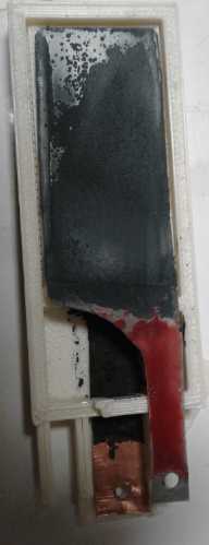 (29th)
Unfortunately there must have been more something coming from the spray
can than met the eye, because the plating came out very uneven,
seemingly with the areas getting the more 'overspray' being those not
getting plated. A couple of times I took it out of the plating bath and
scrubbed the bare spots with 'scotchbrite', to some but not great avail.
(29th)
Unfortunately there must have been more something coming from the spray
can than met the eye, because the plating came out very uneven,
seemingly with the areas getting the more 'overspray' being those not
getting plated. A couple of times I took it out of the plating bath and
scrubbed the bare spots with 'scotchbrite', to some but not great avail.
I neglected to weigh the electrode until after plating it,
so I can't know the exact amount of plating, uneven as it was. (or of
paint.) But it was 5.6 grams, 1/2 a gram more than the previous one.
Egads! In two strips red spray paint was
visible and I had scraped it off with a knife.
But an invisible thin film had covered a large area and prevented good
plating.
Second Cell with Calcium Oxide
instead: Assembly & Testing
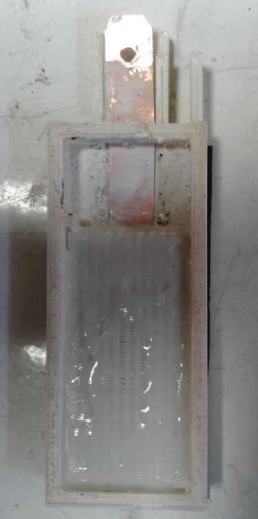 (30th) I put
in the calcium painted copper current collector and the brick of MnO2
mix on top of it. On that I put the separator grille.
(30th) I put
in the calcium painted copper current collector and the brick of MnO2
mix on top of it. On that I put the separator grille.
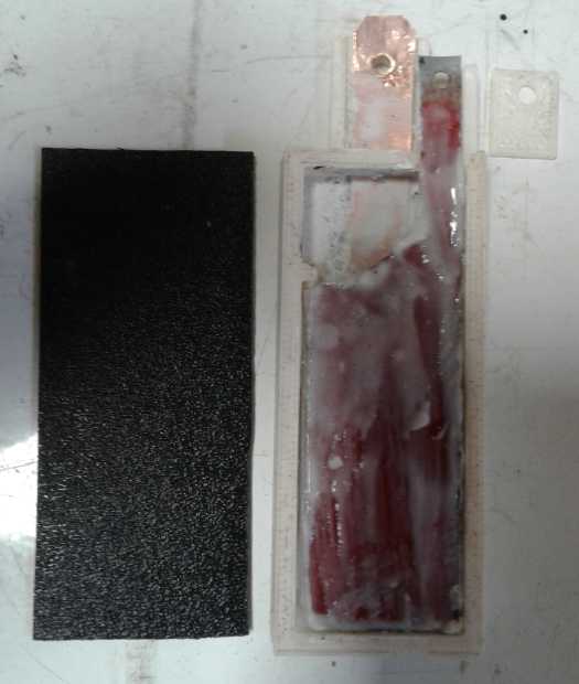 (Oct 1st)
Finally in the morning I heated up some agar. I painted it on the
separator grille (extra insurance) and lavishly (and lumpily) on the
zinc electrode. I glued the cover on. Then I used heat glue to seal
around the terminal slots.
(Oct 1st)
Finally in the morning I heated up some agar. I painted it on the
separator grille (extra insurance) and lavishly (and lumpily) on the
zinc electrode. I glued the cover on. Then I used heat glue to seal
around the terminal slots.
Both the MnO2 and the zinc
didn't seem to quite fill their spaces, and I had to add around 10 cc
of water to see some in the upper chamber. The pH started off about 8,
but as the KOH in the MnO2 mix dissolved it came up to about 13. I
added a little under a gram of KCl salt.
Before I added the salt, charging current was
disappointingly low, just 10-20 mA. With the salt it was up to around
40. (I could really use a better current meter! These ones whose top
scale is 9.99 amps, and whose next scale down has such an internal
resistance in it that it notably drops the current it's supposed to be
reading, are for the birds!)
After half an hour, short circuit current was up to 150
mA. pH was still a little below 13. Probably it needs stronger
electrolyte. Hours later it was over 220 mA.
Perhaps most notably, with the wider lip, which I sanded
flat, and then scraped clean just before gluing, the cell didn't seem
to leak. No pool of liquid formed underneath the cell. But the water
level went down, and later there was indeed liquid underneath. I
noticed on the back some small whitish patches. There was the clue. I
painted the calcium on the inside. The only way to the outside
was if it seeped through pores in the plastic. That explained the leaks
in the printed plastic cells! They weren't at the seams, they were
right through the walls. Using the slicer for the old printer and a
lower print temperature was a good way to do the 'porous' grilles, but
apparently I would have to find the 'right' slicer software for the
cases to prevent them from being rather microporous too.
I dumped what little free liquid there was and cleaned off
the leaky face of the cell, cut and pasted a sheet of thin ABS onto it,
and refilled it. After a little charging I connected a load. With 33
ohms, voltage went down to 1.104 volts. I dropped in a few more grains
of KCl salt, and then a few more flakes of KOH alkali. The voltage rose
in a minute or so to 1.137 volts and the current from about 30 mA to
33. In a few more minutes it started dropping again, but obviously more
electrolyte helped. (It must have been pretty weak since I had
originally added water to the cell, and now had refilled with more. And
the cells had started with an unknown amount of KOH in the MnO2 dry
cell mix. There was enough liquid to test pH, but nothing like enough
to suck into a specific gravity tester to see how concentrated it was.)
I wonder how much of the low current capacity of my more
recent cells is poor electronic conductivity, and how much is poor
ionic conductivity?
I ran the load for 35 minutes, at which point it was still
at 1.011 volts and had delivered about 18 mA-hours. But it wasn't meant
to be a capacity test. I used a flashlight but I didn't see any leaks.
It quickly recovered to about 1.23 volts, and in five minutes to 1.3.
It might have eventually hit 1.35 but I put the charge back on.
(Oct.2nd) There was a pool of liquid under the cell again. I guess it
must have leaked around the edges as well as on the face. I took both
3D printed cells and sprinkled methylene chloride on them with the
eyedropper, one face at a time, and smeared it around with my finger.
Hopefully that would seal up little "pores" that were gradually letting
out the electrolyte.
I filled both cells with water (let's see before adding
more electrolyte) and started charging the original one. It started out
over 100 mA. Would it come back to the performance it had originally
had? What concerns me most is that if the agar jell dries out it cracks
and flakes off. But probably even the older one was still damp inside.
I consider that the cells didn't initially seem to leak.
When I mushed a bit of modeling clay over the filler opening, they
probably built up a little pressure until one of the seams in the 3D
printing cracked open. (The modeling clay was supposed to come loose
and let it out. The seams were weaker.) This time I didn't push the
modeling clay down. Neither cell had liquid under it the next morning.
Cell #1 again - & Better connection to graphite foil terminal
I connected the charger to the older one and found that it
seemed to work just as well as at its best, even with the obviously
weak electrolyte which would have been well diluted by all the added
water. It put out 300 mA short circuit current. It again held good
voltage a long time (not as long as at its best, but it may not have
been quite charged) But the storage capacity didn't seem to have been
revived. I had previously understood that no oxidation level of
manganese was an insulator or passive, but I recently read one common
discharge state was. (It was either Mn2O3 or MnOOH. Actually, that
explains some things I hadn't understood, going back over the years.)
Next thing to try is oxalate salt, to jump the stubborn
(perhaps passivated) substance Mn?O? by two electrons at once. On the
evening of October 3rd before posting this newsletter I tried adding a
gram or so to the present electrolyte before 'switching' to it. First
noted results seem excellent with current capacity and seemingly
storage increased, and charging to a higher voltage. But that's a very
preliminary assessment. More definitive results will have to await next
issue.
(Next maybe some salt with sodium instead of potassium?
Sodium sulfate works wonders de-passivating lead sulfate in lead
batteries. Then there's pulse charging. Worst case: If nothing else
proves durable, nickel oxides - jelled zinc in alkali always works
well.)
On the morning of October 3rd I thought, if the contact
resistance of the graphite foil to metal was the biggest problem, maybe
I should put a washer on both sides of the foil... but the rear washer
behind probably wouldn't contact, or at least have reliable contact, to
the bolt anyway. Then I thought to make a "U" of copper foil, two
holes, and put it over the top of the foil. It would connect through
itself. After that, the performance was only slightly better (if at
all), but the voltage under load read the same on the graphite foil as
on the copper. I seemed to have achieved the objective of lower contact
resistance.
IF I was to use graphite foil as a current collector, if
nothing done with copper seemed very reliable, the best improvements
might be just to make it the full size to fit under the whole electrode
for good connection to all points of that, and to make the tab to the
terminal wider - and to put a copper foil "U" at the connection point.
One could no doubt get acceptable current capacity for off-grid
applications. (And then maybe DieselKleen could improve conductivity
inside the electrode itself, and to the graphite foil?)
http://www.TurquoiseEnergy.com
Haida Gwaii, BC Canada