Turquoise Energy News #137
covering
October
2019 (Posted November 5th 2019)
Lawnhill BC Canada
by Craig Carmichael
www.TurquoiseEnergy.com
= www.ElectricCaik.com
= www.ElectricHubcap.com
Month In "Brief"
(Project Summaries etc.)
- House - New Chemie Batteries - Ground Effect Vehicle - Two Lithium
Battery Charger Circuits; AC and DC Sources - Internet! - Planetary
Gears!: Miles Truck & Chevy Sprint
In
Passing
(Miscellaneous topics, editorial comments & opinionated rants)
- Gardening, Growing Barley, Processing Grains into Flour With
Common Kitchen Appliances - Hair Preservation with Recap - Continuing
Fatal Financial Flops - Small Thots - ESD
- Detailed
Project Reports
-
Electric
Transport - Electric Hubcap Motor Systems
* Ground Effect Vehicle (R/C Model)
- Ultimate Key to Longitudinal Stability and Pitch Control: a Canard -
Modern Fabrics and Paints
* EV Transmissions: Off-the-Shelf Planetary Gears, More. (Miles
Truck & Chevy Sprint)
Other "Green"
Electric Equipment Projects
* Working with the Handheld Bandsaw Mill (& Alaska Mill)
Electricity Generation
* 5 Blade Windplant
* My Solar Power System: - Monthly
Solar Production log et cetera - 8 months! Notes.
Electricity Storage
Turquoise Battery
Project
(Mn-Zn or Ni-Zn in Mixed Alkaline Salt electrolyte)
* Electrolyte to Depassivate Discharged Manganese Oxides? - Air Leaks?
- Bleach - Nickel Oxides Electrode - Making NiOOH - Better Technique -
Paste Electrodes? - 3D Printer Insulated Surround
-- Other Battery Related Projects --
* Honda NiMH Hybrid Car Batteries (installed in solar system)
* Two Lithium Battery Charger Circuits: for AC and DC Power
I note on November 1st that
this is the third anniversary of my viewing of the house at Lawn Hill
on Haida Gwaii where I now reside. While it's an odd layout, I
certainly lucked out getting this particular spacious, well built and
still pretty new place, with its big workshop and a storage room the
same size under it, two garages, on five acres and with a lovely sandy
ocean beach.
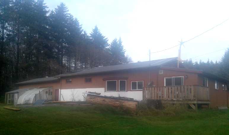 South side of house with new
5-blade windplant,
porch,
South side of house with new
5-blade windplant,
porch,
livingroom bay window, last section of spruce log
to mill (debarked, with metal roof pieces cover ...and
some remaining bits of clutter from the 2nd last section),
small bedroom windows, back door of garage and workshop,
solar panels on roof and on lawn, 'double' greenhouse.
The white painted wall behind the garden gives
more much needed light to the plants near the wall.
(There's a wire fence. The deer haven't figured out they
could go up and across the porch into the garden.)
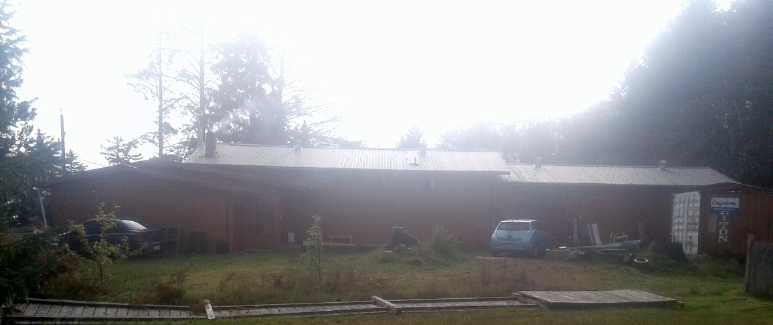
And here's the north side as seen from my neighbor's yard.
(My fence with rotting posts blew down in a high wind.)
[...and what was with my camera that day? Fog on the lens?]
I think my angels must have
worked overtime to get it for me because I was somewhat clueless at the
time and thought I wanted a much cheaper but older and inferior
"fixer-upper" place 15 Km north of it. I would have had far more money
left over, but I would have been spending my time fixing it up instead
of doing more valuable projects. It would have been notably farther
from town and is so low lying as to be in jeopardy if - when - sea
levels rise. (What was I thinking?) But it had just been sold and this
place was the only acreage left on the east coast where I wanted. From
viewing it, I knew it was nice, but it was just a quick look and I
didn't have all the details. Once here I gradually recognized how ideal
a place it is to live and work.
On October 7th and 8th I finally did a last polish on the application
to the "Charge the Future" battery challenge and sent it off. Not that
it was very polished. In January we'll hear whether those who have been
awarded some funding includes Turquoise Energy.
According to the information on line, they are expecting
funding recipients to just be starting with a concept for a better
battery, and hoping the recipients will be able to use the funds to
make a working prototype by the end of the project. I am starting with
essentially working prototypes after already working on the R & D
for 12 years unpaid, and I hope to use the funding not only to improve
them via more R & D, but to start actually producing batteries by
the end of the project. I hope they are thrilled with that prospect.
After that, if manufacture and sales can be made viable as I hope, it
should fund itself and even provide some funding for other projects.
New Chemie Batteries
I'm not very ready to manufacture batteries yet, but every
month brings improvements. The lagging item now is better positive
electrodes. At this point I don't care about the exact chemistry.
Nickel oxides electrodes work even if nothing else I try does. The
other components all seem to work well except for the warping,
ever-leaking cells, and that's just a matter of getting and installing
the proper software for the new 3D printer - or maybe even just turning
up the extruder temperature another 10 or 20 degrees.
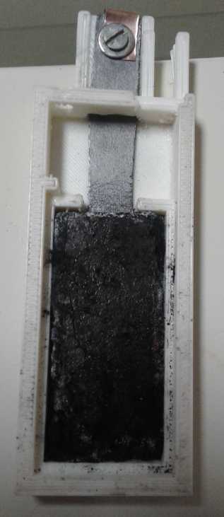
Nickel oxyhydroxide
electrode on a graphite
foil current collector in a 3D printed "test
size" battery
cell case.
 At the start of October the only cell that had worked and
recharged reasonably well was the nickel oxides-zinc one in alkali,
using nickel oxide electrode chunks taken from a commercial NiMH cell.
The
difference between it and any other nickel-zinc battery was the jelling
of the zinc that should make it very long cycle life instead of very
short. So it would be something of special value to produce, even if
none of
the other experiments and ideas were to work out.
At the start of October the only cell that had worked and
recharged reasonably well was the nickel oxides-zinc one in alkali,
using nickel oxide electrode chunks taken from a commercial NiMH cell.
The
difference between it and any other nickel-zinc battery was the jelling
of the zinc that should make it very long cycle life instead of very
short. So it would be something of special value to produce, even if
none of
the other experiments and ideas were to work out.
But before the end of the month I had made a cell with my
own gelled nickel oxides electrode, and proven that it works with
chloride salt in the electrolyte as well as with just hydroxide. The
amp-hours is low, and this must be the nickel "+" side's problem,
because the zinc (even the very same electrode) has worked better with
other "+"es. I am confident of being able to make further chemical
improvements as well as to get decent overall performance from whatever
chemistry is used.
The chemical improvement I really want to get working is
the nickel manganates positive electrode. It should have higher
currents than nickel oxides, more amp-hours, and recharge properly,
which plain manganese oxides don't seem to do. The other item is the
calcium-copper oxide coated copper positive current collector. If it
works it should allow substantially higher currents than graphite based
current collectors. Those items will be the November (and maybe
December) battery research focus.
Ground Effect Vehicle
 But at last I got to some other projects besides new chemie batteries
this month. I came up with yet another exciting new idea for the ground
effect vehicle: a front canard replacing the rear elevator of all
previous ground effect craft. Flying so low, a ground effect craft has
great need of being able to respond instantly to gain and loss of
ground effect lift as it goes over waves, without gain or loss of
altitude. A rear elevator can only respond indirectly by lowering the
tail even more than the wing is already dropping. That's not okay when
flying so close to the water.
But at last I got to some other projects besides new chemie batteries
this month. I came up with yet another exciting new idea for the ground
effect vehicle: a front canard replacing the rear elevator of all
previous ground effect craft. Flying so low, a ground effect craft has
great need of being able to respond instantly to gain and loss of
ground effect lift as it goes over waves, without gain or loss of
altitude. A rear elevator can only respond indirectly by lowering the
tail even more than the wing is already dropping. That's not okay when
flying so close to the water.
The canard can itself gain or decrease lift at the bow
almost even before altitude is gained or lost, keeping the height
steady and level. I visualize a microcontroller operated canard, so the
human operator only has to control the throttle and steering controls.
Liftoff and setdown will (maybe) be handled automatically as the speed
is increased or dropped. It is said that ground effect craft have been
restricted to flying over pretty calm water. With a canard I expect
this one will be much more seaworthy.
Perhaps I should have thought of this much sooner - after
all the only airplane I've ever flown was a Vari-Eze with a rear
propeller, swept back wings and a front canard. (Okay, I only kept it
level and on course for a while while the pilot smoked his pipe. In
1985.)
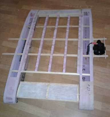
And I even did a little actual work on the R/C model. I
made and mounted the canard and made the rear elevator (which now will
just be a fixed rear end of the wing - maybe adjustable for trim). I'll
seal all the fabric with Minwax "Polycrylic", which model airplane
makers have been raving about recently as a superior replacement for
nitrate/cellulose dope - and even for products specifically made to
replace that dope.
The position of the canard (pretty much the only place I
could have put it at this point in the construction) seems ideal: not
only does it deflect air up and down as it is lowered and raised, but
it deflects it right over or under the main wing, magnifying its lift
changing effect.
And on November 5th before posting this, I realized that a
better place for the ducted fans would be to mount them on the canard.
I'll make that change. Better and better!
The potential to really open up the BC north coast, isolated
islands and other hard to get to places is more there than ever.
Windplant
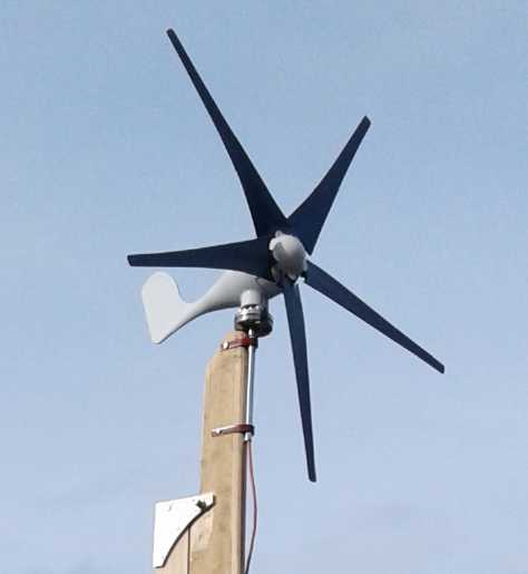 I
installed my windplant the day before a huge storm. I
wired it up after finally figuring out what to do, on a day with enough
wind to test it. I used the MPT-7210A boost charge controller that had
once been running my DC solar system. It looked good and spun well, but
the output wasn't a lot. In the storm if things had been configured it
might have hit 100 watts.
I
installed my windplant the day before a huge storm. I
wired it up after finally figuring out what to do, on a day with enough
wind to test it. I used the MPT-7210A boost charge controller that had
once been running my DC solar system. It looked good and spun well, but
the output wasn't a lot. In the storm if things had been configured it
might have hit 100 watts.
On the evening of the 21st a chair blew off my porch, the
power went out almost all night, and a section of my fence blew over.
The posts had rotted away at ground level. Wind! Great - more work! I
decided
to leave it down. Firewood!
But the next day I finally came up with a plan for
connecting the windplant into the DC power system to charge the
batteries: with an MPT7210A boost solar charge controller. It could
take the lower voltages from the windplant and boost them to charge the
36 volt DC battery system. It was about right to handle the range of
voltages I was getting from the windplant.
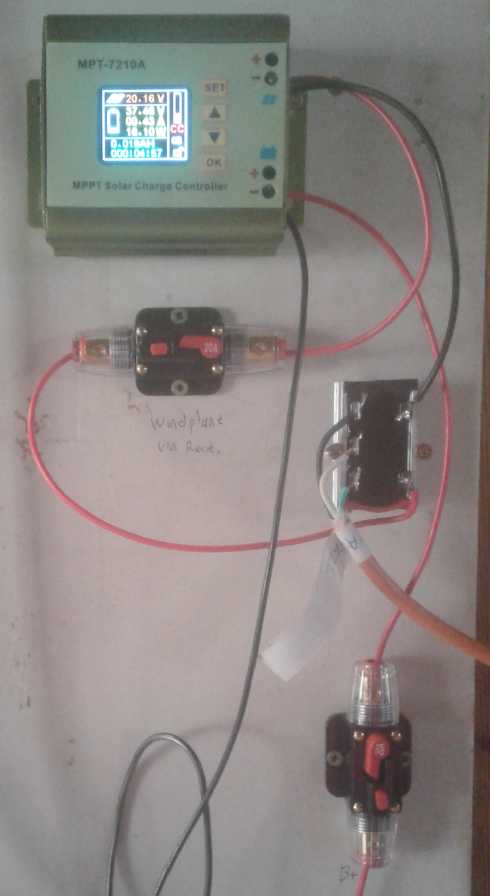
The new
windplant components
on the solar power board wall:
Boost 36 volt charge controller; circuit breaker on input, 3-phase
diode bridge from 3-phase windplant, and circuit breaker on output
to batteries. (I think it says 20.16 VDC on input from windplant
via
the diode bridge, 37.65 V out, .43 A, and 16.10 W output to batteries.
 In moderate wind the next day I wired it (23rd). It put out 10 to 20
watts. Then it sat motionless for the rest of the month and beyond.
There were maybe 5 or 6 days in October it would have done much of
anything. Getting
occasional moderate and high winds and being in a "normally windy"
place are two
different things. Masset gets more wind, but tidal power is by far the
best bet for this island.
In moderate wind the next day I wired it (23rd). It put out 10 to 20
watts. Then it sat motionless for the rest of the month and beyond.
There were maybe 5 or 6 days in October it would have done much of
anything. Getting
occasional moderate and high winds and being in a "normally windy"
place are two
different things. Masset gets more wind, but tidal power is by far the
best bet for this island.
The front of the house roof was the best available
place (failing putting up a huge tower above the trees), but windspeeds
there were only half what they were on the beach at low tide away from
all obstacles. Since power depends on the cube of the wind speed, 1/2
the speed means just 1/8th of the power. In "no wind" there's no
difference.
This also meant my worries about it over-revving in a
storm were doubtless unfounded. It didn't need any high wind
protection. It was rated for 160(?) Km/Hr winds anyway, and 200 Km/Hr
winds would only be 100 owing to its sheltered location.
The one thing that might
drastically perk up its performance in the lower winds it does get
would be a venturi duct, but building that would be too much of a
sideline at the moment.
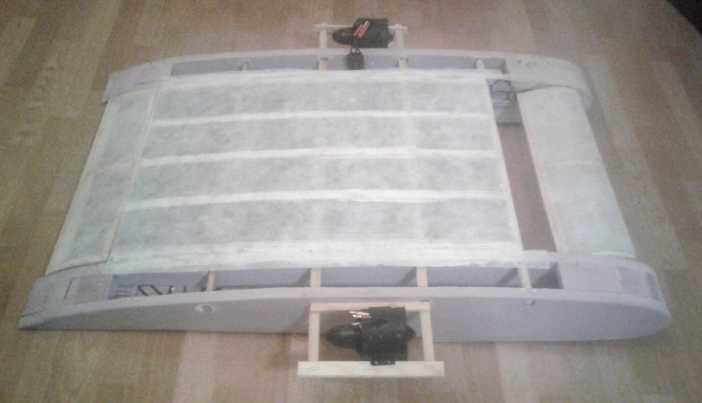
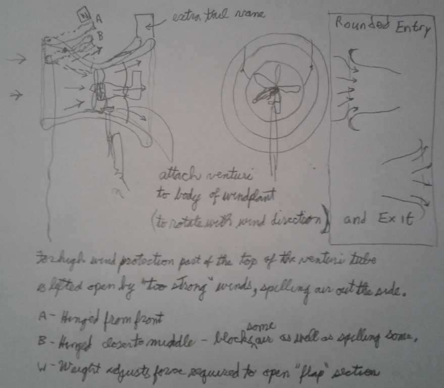 The venturi duct idea.
Capturing twice the frontage area into the same size propeller means
double the wind speed at the propeller and hence 8 times the power.
(To actually capture twice the wind the opening must be more
than double the area to account for inevitable friction losses.)
In conjunction with testing the windplant I added a
switch to the kitchen hot water heater. The third element can either be
shorted out by the switch, or in series with the other two to reduce
the power demand. In the DC system, that makes it either around 250
watts or 160 watts. In the low winter sun, I wish I could turn it down
even more! (Hmm... a DC to DC converter could do that by lowering the
voltage.)
Two Lithium Battery Charger Circuits - AC and DC Sources
Since my NiMH batteries weren't perfoming well in the
solar power system, and since I had some lithiums, I gave thought to
how to effectively charge that type without risk of some of them going
over-voltage, since they have almost no tendency to balance each other.
Lithium open circuit cell voltages are very specific:
* under 2.8 volts is deleterious
* 3.29 volts or less is pretty low or discharged
* 3.32 volts is fairly well charged
* 3.34 volts and above to 4.2 is fully charged
* above 4.2 risks failure
Once they are charged they can go to very high voltages without
drawing any appreciable current, but they are at risk of failure if
they go over 4.2 volts. I didn't want to use the power wasting voltage
shunt boards that can be placed on each cell to keep it below 4.2
volts. (I have some from the Swift, but some of them are quite
corroded.)
I started by thinking of charging each cell separately
with a 3.4 to 3.6 volt source. Then I realized one could charge two
cells in series at 6.8 to 7.2 volts without any risk of the better one
rising to the 4.2 volt maximum limit, since the low one will never be
under about 3.3 volts. That would cut the number of chargers in half -
much better. Then I determined that even if three cells in series are
charged at up to 3.6 maximum volts each or less (10.8 volts maximum),
none will go overvoltage. When 12 volts (four series cells) is reached,
the danger of imbalance causing overvoltage on the stronger cells
begins, and it gets worse from there as the number of cells and voltage
increases.
So instead of charging a 36 volt bank with one charger,
one can charge it as four 9 volt banks of three cells, at 10.5 volts or
less, without any "Battery Management System" ("BMS"). (The generally
recommended 3.6 volts per cell is the very maximum for three cells in
series - 10.8 volts total: a little less is better. To go any higher
than 3.6 per cell, only two cells can safely be charged in each string.)
(Nov. 3rd... Hmm, actually for trickle charging (eg,
solar) 12 volts/4 cells in series per charger would be all right at
under about 3.35 to 3.50 volts per cell, total 13.4 or even up to 14.00
volts.)
 Three 100 amp-hour, 12.8 volt
lithium batteries
in parallel.
Three 100 amp-hour, 12.8 volt
lithium batteries
in parallel.
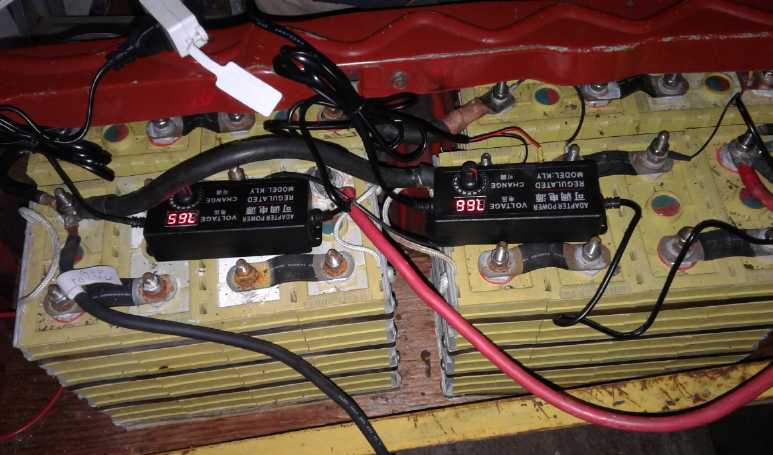
The two 5 amp chargers each charge a 6.4 nominal volt, two
series cells section up to 7.2 volts: [0 to 7.2], and [7.2 to 14.4].
Details in detailed report under "Electricity Storage".
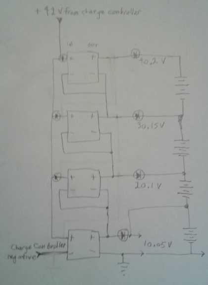
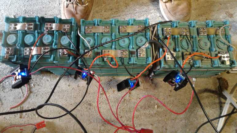 Four DC to DC buck converters
adjusted to 10.05
volts each, charging a nominal
Four DC to DC buck converters
adjusted to 10.05
volts each, charging a nominal
36 volt lithium battery as four 9 volt sections. Note the diodes
soldered on in
many places: see circuit diagram under "Electricity Storage".
To do it with DC from a
solar charge controller proved to be a different kettle of fish. There
don't seem to be any adjustable or 'right voltage' isolated output DC
to DC power adapters. I contrived to make a "totem pole" arrangement
with non-isolated DC to DC buck (voltage reducing) converters, but I
had to try several variations, and they ended up needing 7 isolation
diodes, on both inputs and outputs, and if the charging voltage is
insufficient, the top bank won't get charged. (If that insufficient
charge voltage rises as the lower ones charge, the top ones will charge
last.) In a variation, if the voltage to the top set of cells is too
low, one might use a DC to DC voltage boost converter instead of a buck
converter for that top set. (or even 2 or 3 or all sets - a wide range
of charge voltages could thus be accommodated.)
In trying to do it with the PowMr solar MPPT charge
controller, thorny problems cropped up and I finally realized it simply
couldn't be done with a charge controller that gets its own power off
the batteries on the same connection that is also its charging power
output (almost all of them). A battery can't charge itself when there's
no solar coming in, but the voltage has to be there and they will try,
which can only run them down. However the MPT7210A boost charge
controller draws its power from the solar panels instead. It should
work with that one - I hope - but I didn't get to actually trying it so
far.
Internet!
On the 27th was an event which will be most helpful: the
fiber optic internet was at long last hooked up! That was supposedly to
have happened shortly after the time I moved up here from Victoria. It
took over 2 extra years, but it's here at last. That still doesn't give
the whole island a truly good connection to the mainland, but that's
supposed to be coming too. Already it's far better than the
"connection: poor" pirate WiFi from a very slow satellite link. (I went
to a page and waited for it to reload... it seemed awfully slow. Then I
realized it had already reloaded in the time it took me to glance back
at the window after clicking the mouse. What a change after typically
waiting 15-45 seconds for it to maybe load a page!)
Handheld Bandmill
I was still, very gradually, milling my last spruce log in
October. (As of November 3rd I'm finally cutting into the last 12 foot
section.) I had lately noticed the bandmill seemed slower than usual.
But why? It finally turned out to be the new smaller V-belt pulley on
the saw - the band was actually going too slow.
And I had had about enough of re-welding washers onto the "railway
wheel" band guides, so I ordered some alternatives. See the 'detailed
report' under "Other Equipment Projects" for more.
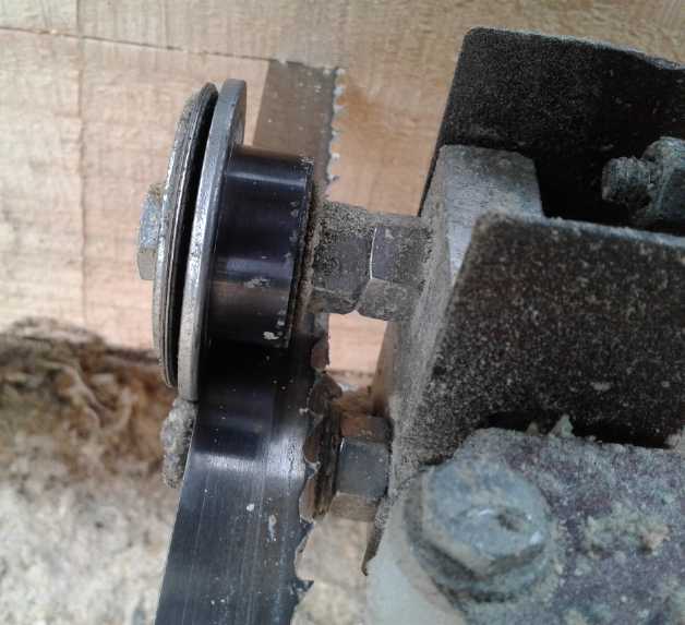 New "yoke roller" and "thrust
bearing" band
guide
New "yoke roller" and "thrust
bearing" band
guide
I am planning to make and post a video of a take-apart of
my fine bandsaw mill to help those who would like to build one
themselves. After I'm finished milling those last big lumps of spruce!
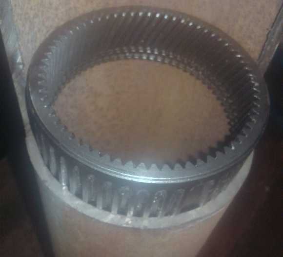
Planetary Gears! Miles Truck & Chevy Sprint
I found something I've somehow never managed to find
before (but probably available all along): planetary gear gearsets
already fully assembled -- ready to use drive components. (at "Anaheim
Automation") To say the least they weren't cheap. But I had decided to
replace the big, ugly, lossy transmission in the Miles truck with a
simple efficient planetary reducing gearbox. A helical gears unit
promising up to 97% efficiency seemed like just the thing. I knew
planetary gears must be more efficient but I was surprised that it was
so high. There's the "ultra efficiency" I'm always after for EVs.
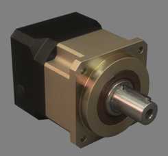
GPBS90
Planetary Gearbox
 I
worked out that a 5 to 1 reduction unit should be about
right for the Miles mini cargo truck, with the rear differential
contributing a further ~ 2.16 to 1 for a total of 10.8 to 1 from motor
to wheels. I picked a model to order and have been in touch for
details. Having the Curtis programmer I can increase the maximum motor
RPM a little, and with the extra efficiency 10.8 is surely a slightly
reduced overall reduction ratio. It still wouldn't turn the truck into
a highway speeds vehicle, but it would be up to at least 60(?) Km/Hr
instead of 40 with less waste of battery power over distance, and so it
would be much more useful than at present.
I
worked out that a 5 to 1 reduction unit should be about
right for the Miles mini cargo truck, with the rear differential
contributing a further ~ 2.16 to 1 for a total of 10.8 to 1 from motor
to wheels. I picked a model to order and have been in touch for
details. Having the Curtis programmer I can increase the maximum motor
RPM a little, and with the extra efficiency 10.8 is surely a slightly
reduced overall reduction ratio. It still wouldn't turn the truck into
a highway speeds vehicle, but it would be up to at least 60(?) Km/Hr
instead of 40 with less waste of battery power over distance, and so it
would be much more useful than at present.
I don't have enough lithium batteries at present to do
both the truck and the Sprint to desired capacity, but if I put 2/3 of
them into the truck for 7200 watt-hours I'd have a useful range
vehicle. (IE, it could at least make it into town from here. It would
surely be useful around town.)
And then, here I've been fiddling around all this time
with planetaries from auto transmissions trying to do the variable
torque converter in the Sprint, and trying to figure out how to fit the
components together outside of a proper case, with much trouble and
limited success. But starting to think of the cast housings of the
ready-made units, why could I not make my own suitable enclosed
housing, out of pieces of pipe big enough to enclose the entire gear
and shafts, and turn internal and end bearing plates, and a mounting
for a chain sprocket, on the lathe?
On November 1st I happened to visit someone who had scraps of pipe in
his shop and got a piece of heavy steel pipe that would be ideal for
the housing. And with custom turned end pieces enclosing it, I could
put proper gear oil inside. Suddenly the planetary gear + centrifugal
clutch infinitely variable torque converter seemed much closer and more
promising.
Free Outboard
Earlier I had looked at the
"refuse transfer station" for a pipe. Instead I found discarded
outboard motors. I took a smaller one for a potential electric outboard
conversion. Just in case. Sometime. Maybe. I also 'scored' a big chunk
of 1/2" thick stainless steel plate. That could be good for battery
electrode punches and dies.
 Not bad, but where is its hat?
In Passing
(Miscellaneous topics, editorial comments & opinionated rants)
Gardening - Growing Barley
- Processing Grains into Flour With Common Kitchen Appliances
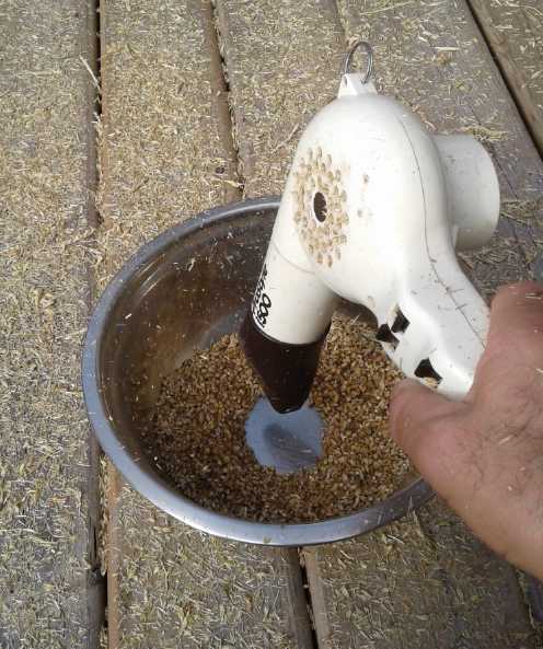 In the spring I planted barley. It was one of the few things outside
the greenhouse (besides potatoes and peas) that did well in the clouds
and cool weather this northern summer. It probably wasn't much more
than 50-60 square feet in all (ie, something like 7' x 8'). I threshed
the heads in a blender. That broke up most of the chaff from the seeds.
Then I winnowed them in a mixing bowl, shaking the bowl and with a hot
air hair dryer blowing the light chaff out. There were still husks on
some. I rubbed the grains between my hands and blew again, but it
didn't help much. Now what? I suppose I could grow barley sprouts,
which are said to be very good for you - and for which I had originally
bought the seeds.
In the spring I planted barley. It was one of the few things outside
the greenhouse (besides potatoes and peas) that did well in the clouds
and cool weather this northern summer. It probably wasn't much more
than 50-60 square feet in all (ie, something like 7' x 8'). I threshed
the heads in a blender. That broke up most of the chaff from the seeds.
Then I winnowed them in a mixing bowl, shaking the bowl and with a hot
air hair dryer blowing the light chaff out. There were still husks on
some. I rubbed the grains between my hands and blew again, but it
didn't help much. Now what? I suppose I could grow barley sprouts,
which are said to be very good for you - and for which I had originally
bought the seeds.
 Anyway I ended
up with 270 grams of seeds, over 1/2 a pound. If I want there should be
enough grow a much larger patch next year. (The original seeds will be
about 4 years old.)
Anyway I ended
up with 270 grams of seeds, over 1/2 a pound. If I want there should be
enough grow a much larger patch next year. (The original seeds will be
about 4 years old.)
To complete the grains processing plot, while I haven't
used the barley, I have ground quinoa into meal or coarse flour, and
wheat grain into coarse flour, with a coffee grinder. Less grain in the
grinder makes a finer grind. Grinding a bigger batch longer, even a lot
longer, doesn't make it fine. (I've just made a nice applesauce
cake with the wheat flour. I'm going to try planting winter red wheat
today (Oct. 10th). Done.)
I often add quinoa flour to bread in place of some of the
wheat flour. (Too much makes the bread rather crumbly - I'm just now
trying 1/2 cup out of 4 total cups of flour instead of a whole cup, so
a hamburger won't fall apart. Yes, that's better.)
So there it is: grains can be grown in the garden and
processed into flour with common household small appliances. There's no
need to buy anything more special than these three common items. Of
course this was just a "test" and one would want a much bigger plot to
get a really useful amount. (The quinoa gave the most grain from the
same small plot.)
And here are some
gratuitous pictures of some of my greenhouse produce, which did
surprisingly well, eventually, after the all-cloudy July we had.
 Greenhouse Produce mid October
Beans, peas, cherry tomatoes, cherry hot peppers...
and a foot long cucumber that cleverly hid behind 3 leaves.
 And "coastal star" romaine
lettuce seeds,
cabbage, hot red peppers, leek,
And "coastal star" romaine
lettuce seeds,
cabbage, hot red peppers, leek,
cauliflower, cherry tomatoes, pole beans and a more reasonable
cucumber.
(Only decent cauliflower I've ever grown! it was delicious.)
 A single cabbage, left to grow
for a second
year, filled a greenhouse bed.
A single cabbage, left to grow
for a second
year, filled a greenhouse bed.
Earlier it sprouted several branches and grew enough seeds for a whole
farm. In the fall it grew some funny clusters of leaves and two more
very nice (if smallish) heads of cabbage. (with a third one maybe
coming.
The fourth, farthest right in the cluster, is actually
a separate
cabbage, planted this year, which has yet to make a head.)
 After getting three lovely big
boletus
mushrooms at the edge of the
After getting three lovely big
boletus
mushrooms at the edge of the
highway in early October (and cooking and freezing them), now all I
find is a couple of wormy ones,
...and oodles of deadly poisonous amaneta muscaria
Hair
Preservation
with
Recap
I started putting a towel on the pillow on my bed, and I
pulled it
down
to cover my scalp. This kept my head warmer at night, which evidently
should
help prevent thinning hair and baldness. It didn't always stay when I
rolled around, and usually got lost somewhere before morning. But it
was much better than nothing. (Now I think I know where the term "night
cap" came from. Before good house insulation and heating, probably lots
of
people wore them in bed. Probably something like a light tuque or
beanie.)
Later in the month, I tried putting a pillow up on edge,
above and
behind my regular pillow, sort of between it and the wall, so the top
of my head goes against it. I used a down/feather pillow - smaller and
easily shaped. That seems to work pretty well.
So now to recap, to fight thinning
hair we have:
- tuques, beanies, caps and hats for wearing in cool and cold
temperatures (indoor and out)
- extra pillow 'overhead' or a nightcap for sleeping in cool to cold
bedrooms
- frequent shampooing/showers, leaving shampoo on scalp for a couple of
minutes or more (and some shampoos are evidently better than others)
- at least a daily hair brushing for more scalp stimulation than using
a comb
- once a month spraying or rubbing of ethyl alcohol on the scalp to
kill any deleterious bacteria, perhaps clean out pores and hair
follicles, and perhaps cause some
vaso-dilation. Ethyl rubbing alcohol and vodka have both been used.
Vaso-constriction of scalp blood vessels, usually from
cold scalp, is evidently the biggest culprit that causes
hair follicles to become "dormant" and stop growing hair. But there
seems to sometimes be some sort of bacterial or perhaps mite infection
component or cause, too, and or possibly just accumulation of dead skin
in hair follicles. (I think I had some sort of mite infection once -
little scabby bumps here and there all over my scalp. They could be
scraped off with a fingernail. Daily shampoo eventually cleared them
out.)
Continuing Fatal Financial Flops
* Well... The US "Fed"s incredible volume of money printing didn't end
after a few days or on October 11th as they promised. Instead the
amounts are growing. (along with those of the ECB, Japan and China. In
fact one or more of these institutions has always been printing money
since 2008, serially. Now it's all together.) Now they're saying it may
be a "permanent" fixture of the financial system. What kind of fairness
is it that the banks and the banking system give themselves free money
while the rest of us get more and more poor? Where are the bailouts for
the average person? Where are the low interest rates on our
debts? These everlasting, ever growing central bank balance sheet
expansions can't end well.
Be prepared for some big eruption of the financial system.
It has for some time now been strongly advisable to pull some cash out
of your account to cover at least a couple of weeks' groceries, gas and
so on. And if you've become used to paying for everything with a debit
card, you may be astonished to discover how fast cash evaporates from
your wallet these days. A couple of hundred bucks can easily be gone in
a day - even in one gas fill-up for some, or just stocking up a few
groceries.
Small
Thots
* Energy Equivalencies [Below: Canadian dollars, BC residential
electric rate ~12 ¢/KWH,
imperial gallons.]
-
Diesel is said to contain 3.65 KWH/Liter when burned in an efficient
generator. Diesel should then cost about 43¢/liter to be
competitive
with power grid electricity.
-
It is said that a boat outboard motor burns about 1 gallon of
gasoline per hour per 10 horsepower.
-
One horsepower is about 750 watts, so 10 HP for an hour is 7.5 KWH. Per
liter, that's less than 2 KWH, when burned in an outboard. So to be
competitive a liter of gasoline should cost under 24¢. (Probably
cars are somewhat more efficient than outboards, so they added road
tax.)
* Only 41% of US corn has been harvested instead of the average of 61%,
and now record cold temperatures and snow in the continental USA are
finishing it off. With this, combined with many other crop and food
losses globally, global food scarcities seem inevitable. Prepare.
* Some say China has culled 130 million pigs owing to African Swine
Fever. The USA has 75 million pigs. Others put the death
estimate much higher, at up to 300 million pigs - half of the total
population. Some say this won't end until 70% of the entire Chinese pig
population has been wiped out. There is no vaccine and no cure and it
is contagious. Just kill the pigs and try to keep the remaining herd
healthy. Pigs in China have become seriously overpopulated in
attempting to feed the human overpopulation. It is now spreading across
Asia and Europe. Will it hit the Americas? Some estimate 1/4 of the
world's pigs have died.
"This is a global plague unlike anything we've ever seen before." --
Michael Snyder, zerohedge.com
Not to underplay the seriousness of that situation in and
of itself, the parallel to the human situation is unnerving: we are
likewise overpopulated. A disease that preys on humans and spreads like
African Swine Fever certainly could have the potential to wipe out 2/3
of the human population (especially a malnourished population) before a
vaccine can be developed, and these days it won't stop at any national
border or (with air travel) ocean.
* I solved the mystery of the red spots on my legs. They would seem
to be from mites that live in the spruce or spruce bark in the wood
shed. Apparently they think human legs (or at least mine) are a good
substitute and they contrive to 'get on board' when I bring in
firewood. I bring it in in big garbage pails because they don't drop
bits and the handles are high up so you don't have to stoop down to
pick them up - great for when you have to set them down in front of the
door to
open it. If I spray the buckets off with water frequently, and don't
leave them out in the wood shed, and rest the pail only against my knee
and not my thigh as I carry it, I get very few of them, and only on the
knees.
Witch hazel remains by far the most effective way to get
rid of them once acquired, one wetting of the skin where it is usually
being enough.
When I've finished milling the spruce (soon!) and run out
of spruce firewood (not so soon!) I'll gladly switch to burning alder.
ESD
(Eccentric Silliness Department)
* I've always liked to call a bunch of crows a "crew" because they go
strutting about, inspecting and pecking at things, like workers on a
job site. Recently I've seen a couple of what I could only describe as
"crow conventions" there were so many of them. Or maybe they were "crow
trade
shows".
But someone told me a group of crows was called a
"murder of crows". A little bizarre! I guess people only notice crows
when
they're cawing angrily. According to that analogy, these must have been
"massacres of crows" or perhaps even "genocides of crows"!
* Conpare: to make an unfavorable comparison.
* Discover: to remove the cover to see what's inside.
* The cougher coughed upon the coughee. No one else wanted it after
that, so he added the tin of coughee to his coughers. Having thus "won"
it, he had little incentive to quit coughin' for next time.
* Counting on Puns:
owe - won - too - free - fore - fife - sicks - savin' - ate - nein* -
ton
- all even - doesn'
*nein: the number of words of German I speak.
"in depth reports" for
each project are below. I hope they may be useful to anyone who wants
to get into a similar project, to glean ideas for how something
might be done, as well as things that might have been tried, or just
thought
of and not tried... and even of how not to do something - why
it didn't
work or proved impractical. Sometimes they set out inventive thoughts
almost as they occur - and are the actual organization and elaboration
in writing of those thoughts. They are thus partly a diary and are not
extensively proof-read for literary perfection, consistency and
completeness before
publication. I hope they add to the body of wisdom for other
researchers and developers to help them find more productive paths and
avoid potential pitfalls and dead ends.
Ground
Effect
Vehicle
(first
the
R/C
Model)
Recap of Design Details
In case there are new readers and in general, I'd like to
go over the whole project and put everything that's been so gradually
"accruing" in one place.
I first learned of ground effect craft in March 2017 from
a video 'suggestion' on youtube. From there I found some more info and
soon found a video of a 2011 radio controlled "catamaran" style one,
which seemed impressively stable -- flying just over a paved road. It
seemed to have spawned a few more similar models also to be seen on
youtube. What I gradually came up with as highly valuable design
features were these:
1. The catamaran shape. Two hulls
prevents spilling air off the ends of the wings, increasing the lift
efficiency. The single wing between the two hulls can be smaller, and
longer front to rear than it is wide. The height of the ground effect
depends on the front-back length of the wing(s), so this should give
the highest-up ride for its size. In addition, it's an easy shape to
dock and to maneuver at low speeds. (I made the hulls flat bottomed
(yet with a "step") because I know it takes less power to get a flat
bottom boat planing. We shall see if this proves better for takeoffs.)
2. The central "dorsal fin" vane instead of a rear tail. A
negative 'feature' of ground effect craft in general is that with
little or no banking for turns, tighter turns are difficult. The
catamaran in particular tends to simply fly diagonally on its original
course when turned, before gradually straightening out. The center vane
should counteract this tendency without banking. (If it is tall enough
it will automatically cause banking into the turn.)
3. The special wing profile. The designer of the profile I've
adopted for the 1/4 scale radio controlled model, John Ryland of Ryland
Research, says that unlike typical airplane wings, the suction lift
from above is more to the stern, while the compression lift beneath is
more forward, and that this improves longitudinal stability. (His
little model seemed quite stable as he changed its weight distribution.
Computer modelling assisted with determining the profile.) Whether the
lift to drag ratio is as good I'm not sure.
4. The forward "canard" elevator -- this month's design change:
see below. The canard near the front can respond positively to changes
in pitch - a dipping or rising nose - virtually as they start to
happen. As the front loses lift going over the trough of a wave (it's
suddenly "higher" over the surface and so the ground effect is reduced)
and the nose starts to dip, aiming the canard up adds lift and directly
pulls the nose back up to maintain level flight. Vise versa with a wave
crest.
A rear elevator can only respond to a falling nose by
pushing the tail down, which will level the craft but with a loss of
altitude. To regain the altitude, the tail must be pushed down further
to get the nose up. So the tail loses even more altitude. That's okay
in an airplane even at 100 feet. It's not okay in a ground effect craft
at 1 or 2 or feet. It might hit the next wave crest.
Previous ground effect craft have worked poorly except
over calm water. I expect the front canard will make the ground effect
vehicle considerably more "seaworthy". I plan that it will be computer
controlled for instant response and automatic trim, for a smooth, level
ride without effort from the operator.
5. Ducted Fan propulsion. A ducted fan provides the maximum
static thrust for takeoff from water with the lowest horsepower. My
original idea was one fan - perhaps a gasoline engine in the full size
vehicle.
6. Multiple Ducted Fans. Having left and right propulsion
greatly improves maneuverability when docking. I hope to use electric
propulsion not only in the model but (probably) in the full size
vehicle, and that
would allow reverse as well as forward thrust for maneuvering. There
are new aircraft designs with many small electric ducted fans, and this
might serve well in the full size vehicle as a safety factor - one fan
failure of 6 or 8 fans won't end the flight in the middle of the water
somewhere, necessitating rescue.
A Burt Rutan Vari-Eze two person airplane with front
canard is said to get 40 miles per US gallon at 150 to 180 knots.
That's a very efficient aircraft. A ground effect craft should be even
more efficient. Thus a battery that would fly some other plane 30
minutes might last on the ground effect vehicle for 60 or 90 minutes,
making electric propulsion more practical than for high-flying aircraft.
Ultimate Key to Longitudinal
Stability and Pitch Control: a Canard
Strange how thoughts develop. As I was getting up on the
morning of the 10th my wandering thoughts crossed by the name "Faeroe
Islands", which had been mentioned in an ad on youtube. I wasn't quite
sure where those were (somewhere around Scotland), so then I thought of
the Orkney Islands, off the north coast of Scotland, where powerful
floating tidal flow units are already generating megawatts. Scapa Flow,
the harbor in the middle between the several islands, had been the home
base of the main British fleet in both world wars.
Early in World War Two a daring U-boat commander had
sallied into Scapa Flow underwater in a shallow, narrow channel between
two islands, thought to be unnavigable, and with a torpedo sank a
battleship in the midst of the fleet. No one at first understood what
could have caused the explosion in this "safe" place where the larger
channels were all mined against just such an incursion, and the
submarine got away the way it came.
Then I thought of the bow planes, the "dive planes" on a
submarine that gave it such vertical maneuverability. Then I thought
that if there were "bow planes", front rudders, on a ground effect
craft, it could be more stable. But those would be something else
sticking out the sides, making docking the craft more difficult. (It's
already the one concern I have with the two 'offside' ducted fan
motors.) Then, why should those "bow planes" be separate? Why not have
an elevator on the front of the wing? As the front of the wing rose up
or veered down, its motion or even the tendency toward such motion
could more easily and quickly be compensated for by an elevator
directly pushing the front of the wing up or down. The rear follows the
front. An elevator at the back can only more indirectly respond to the
rise or fall of the wing that has already happened.
Our imagination is always limited by what we already know,
and airplanes we know all have a certain familiar design -- they just
don't have control surfaces on a leading edge anywhere. Even birds have
similarly shaped wings and a rear tail/elevator. Instinctively, control
surfaces at the rear of
an airfoil have negative feedback. They will "return to center" if the
control stick is released. A front control surface, if hinged at the
back, would prefer to jam full up or full down. But the similarity of
the airplane to the bird is deceptive. The bird can minutely maneuver
and aim its whole wing. It can move it forward or back to change its
center of lift. A front control surface, wherever it is hinged, would
seem to be just what is needed for the ground effect craft.
And come to think of it, on a 'canard' aircraft the
elevator is actually in front of the wing. Those fly quite nicely -
in fact I've actually flown one, a Vari-eze that won the 1979
Oshkosh airshow for "best homemade aircraft of the year". (The only
thing I've ever flown. Admittedly I only held it level and on course
while the pilot had a smoke.) Since I already knew of it and had
experience with it, perhaps I should have thought of this design much
sooner and skipped the submarine, but that's how the thought stream
progressed! A youtube video says the Vari-eze gets 40 miles per [US?]
gallon at
150-180 knots. If the ground effect craft is even better, we should
expect amazingly low energy use.
 Vari-eze, a popular homebuilt
front canard,
rear swept wing, rear propeller aircraft.
Vari-eze, a popular homebuilt
front canard,
rear swept wing, rear propeller aircraft.
(designed by Burt Rutan long before he made the "space plane" that won
the "X-Prize".)
I can visualize a front elevator, probably controlled by
computer, responding in real time to the aerodynamic forces that would
cause the craft to rise and fall, a tendency to "hobby horse" in large
wave crests and troughs. Inertial sensors can detect the slightest
change in motion when the nose of the craft starts to rise or fall and
the control would compensate. It could maintain an ideal height with
little variation. Passengers would enjoy a smooth flight even over a
stormy sea. (Even I wouldn't get seasick! ...except maybe in big swells
over larger areas, which it would probably have to follow up and down.)
Here then would seem to be the ultimate key to
longitudinal stability of ground effect craft! This missing key is what
has kept them restricted to smooth water, and from being safe and
practical in real world conditions. Even an intrinsically less stable
craft design could doubtless be made to work quite well, again,
particularly with a microcontroller doing the up-down trimming.
The next question was whether or not I could add some sort
of front control surface or canard to my half-built model. If it made
more lift at the front, it would just be necessary to move the weight
(mainly the batteries) forward in the craft to keep the center of
gravity in line with the lift. Or it could be made "lift neutral" in
center position.
I decided a 'canard' between the two hulls looked doable,
and would be best and most stable. The idea of a front elevator with a
rear hinge as part of the main wing somehow is unappealing. The
previously planned rear elevator, somehow not made yet, could just
become a fixed part of the wing (or for the model could be "trimmed",
adjusted to different positions, to see where it worked best for any
insights that might be gleaned for optimizing the full size vehicle). I
looked at the model. It could either be a very narrow canard (front to
back) very near the front, or it would have to be raised above the
level of the wing. Would a narrow one have enough control surface? The
whole thing could pivot. And it would be well to the front, giving it
maximum up-down aim leverage. I decided that was what I would try.
When people see it, the front canard on a 'catamaran'
ground effect craft will seem so natural -- that is the "obvious" way
to build them. How can it be that no one has thought of it before?
Wright brothers first aircraft had a front canard, and there has been a
century
of not-very-satisfactory ground effect craft. And yet, look at the
circuitous route my thoughts took to suddenly "get it", 2-1/2 years
after first hearing of ground effect craft myself and even having
already had personal experience with canard design aircraft.
Well! (Of all the nerve!) Having mentioned "canard" and
"ground effect" in an e-mail or two, on November 4th ever-ready
Google/Youtube came up with a video suggestion of a very large radio
controlled model ground effect craft with a canard from November 2010
that it had never shown me before even in searches. The maker said it
was made lightweight and went so slowly so they could observe it better
and keep radio control over it without having a high speed chase boat.
The planned heavier human carrying version "will take off" at 120-140
Km/Hr. Call me chicken but my intended cruising speed is around 80-100.
(The intended human carrying craft was to be the same size as the 7.2
meter long model but was apparently never built, for the usual reason:
no funding or partners to be had for a promising new design. There were
some Japanese characters in the video title, but it also included
"Fugure-8 Flight of WISES Model". With the spelling it should be easy
to find.)
His design predates (by only months) the first "catamaran"
model shown (so far) on youtube, but it had wingtip features to
accomplish the same thing. It looks quite viable, but I like mine
better.
And I too am wondering about keeping the model within a good range for
radio control. At least mine is 1/4 scale, so it won't take up quite so
much of the small lake I intend to try it on. His model weighed 57 Kg.
The
1.23 x .76 meter bare body of mine so far is just 1.35 Kg, but it needs
more fabric and more paint and hull decks, and when the motors and
batteries and electronics are added it'll be lots heavier.
Once again, the lack of progress on this project seems to
have miraculously worked out to allow yet another important and
beneficial idea to improve the final design. At some point, it has to
get built and flown, but in the meantime the more improvements that
have come to light, the more confident I am of getting a fabulous,
efficient, stable and practical craft for rapid transportation over
water!
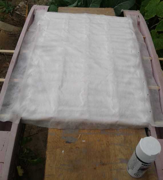
Modern Fabrics and Paints
 Having used up a can of varathane spray paint on the wing
fabric and yet it still wasn't airtight, I decided to simply try some
other paint. I used white 'rustoleum'. One coat (on top of all that
varathane) seemed to make it pretty much airtight. and white. It also
had the opposite effect of cellulose dope on canvas: instead of the
featherweight polypropylene fabric tightening and stretching, it
loosened and went slack. It sagged between the supporting pieces.
Having used up a can of varathane spray paint on the wing
fabric and yet it still wasn't airtight, I decided to simply try some
other paint. I used white 'rustoleum'. One coat (on top of all that
varathane) seemed to make it pretty much airtight. and white. It also
had the opposite effect of cellulose dope on canvas: instead of the
featherweight polypropylene fabric tightening and stretching, it
loosened and went slack. It sagged between the supporting pieces.
This suggests another technique should be used. Next thing
was to take a big piece of fabric and lay it out flat on an even bigger
sheet of polyethylene plastic. Then it would be cut and glued (still
using epoxy, I think) to the airframe in flat sheets. (Luckily there
don't seem to be any compound curves.)
...or could the paint itself glue it to the model? That
might be worth a try! (Actually it seemed to "melt" the polystyrene and
I ended up glad I had done no more.)
(20th) I cut and shaped pieces of wood
for the canard. As I did so I
thought of paints again. I looked up "model airplane dope" on line and
found that there are more modern alternatives. There's one called
"Eze-Dope", and on a seller's website some model builders were saying
how great it was, without odor and fast drying. (No wonder the hobby
store I was in a while back didn't sell aircraft dope any more.) One
customer
commented to that effect in 2014, but then he added a note in
September of this year, barely a month ago. He said after reading
something in a model
aircraft magazine, he had tried MinWax "Polycrylic" and found it was
even better.

 "-----Updated
9/17/2019 After reading an article in Model Aviation, I decided to try
Minwax Polycrylic (satin finish) thinned with water to 33% Polycrylic.
One coat with a wide (1" brush) gave me better results than I got with
two or three coats of Eze Dope. See photo. So, while Eze Dope gave me a
good enough alternative to nitrated dope as a tissue sealer, Polycrylic
is a decidedly better one."
"-----Updated
9/17/2019 After reading an article in Model Aviation, I decided to try
Minwax Polycrylic (satin finish) thinned with water to 33% Polycrylic.
One coat with a wide (1" brush) gave me better results than I got with
two or three coats of Eze Dope. See photo. So, while Eze Dope gave me a
good enough alternative to nitrated dope as a tissue sealer, Polycrylic
is a decidedly better one."
It was nice of the store selling "Eze-Dope" to let him
post that, years later! (I suppose they didn't know.)
I looked that up and some common stores had it, but they
all wanted the customer to pick it up and wouldn't ship it. Then I
found that "Home Hardware" had it. There was one of those in Masset.
That was 85 Km away, but at least driving there didn't involve ferries
and motels and 1000 $. They didn't have any but would order it. It
seemed it would take until the end of the month to arrive. Nothing is
fast when it has to come across BC and then catch the ferry to this
island.
To finish this, I drove up to Masset on November 1st and
picked it up. Then I went down the street to "Co-op Home Centre". They
had it sitting on the shelf - no need to have ordered it at all! Oh
well, Home Hardware was 50¢ cheaper. The co-op also had the
elusive #10-24 threaded rod I had previously been unable to find.
(22nd) I cut and shaped pieces of wood
for the rear elevator, which will now simply be pinned into one
position before each flight. Different positions will be tried along
with different weight distributions front to rear to see what works
best.
I found a 2017 youtube video about fabric and coverings by
a model aircraft builder 'of 40 years experience'. He himself was
trying Polycrylic for the first time. He did three different fabrics
and three different fabric fillers. Here was someone of long experience
with fabric aircraft materials, and he was more than a little impressed
with Polycrylic. It would seem it must be the best! He said he used a
heat gun to tension the fabrics but I don't know if that was before or
after applying the finish.
He also gave the weights per yard of his fabrics. I
measured and weighed a piece of the light PP cloth and found it was 20%
lighter than his lightest fabric: 28 grams per square yard versus 34.
And being PP, it was probably stronger too.
 At some point I started gluing fabric onto the canard and the elevator
with ordinary white carpentry glue, which was suggested in the same
video. It dries a LOT slower on styrene foam than on wood!
At some point I started gluing fabric onto the canard and the elevator
with ordinary white carpentry glue, which was suggested in the same
video. It dries a LOT slower on styrene foam than on wood!
(31st) I finished the canard and elevator, and I mounted the canard on
the craft with a 1/8 inch dowel that ran right through everything from
the left edge to the right. Now it just needed the radio control servo
hooked up to the radio receiver... or to an inertia sensor and a
computer control to automatically adjust the canard for level flight
even in wavy conditions. But that can come later.
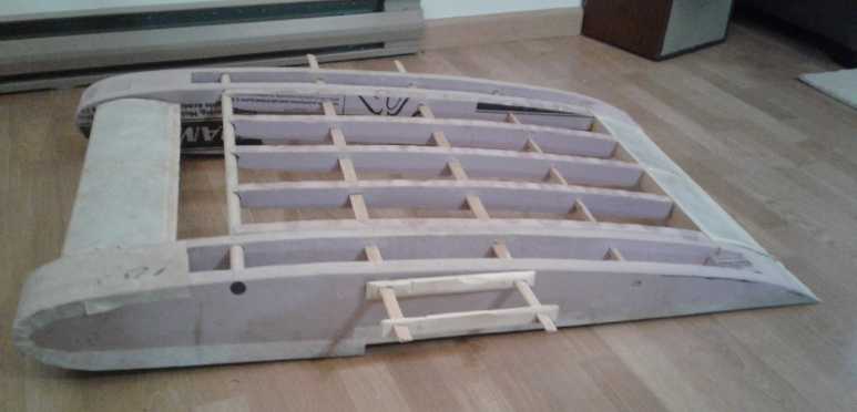
Another profile
With wing recovered November 2nd
(I was going to do the starboard motor mount properly,
but my mini milling machine was again "on strike".)
(Egads, what's with my cell-phone camera today? "foggy")
I am very pleased with the position of the canard. It
could hardly have worked out better if it had been planned from the
beginning. It extends the lifting surface almost to the front of the
hulls, which will in itself improve the ground effect. It also seems to
give some meaning (besides floatation in water) to the hulls extending
so far forward from the wing. Now the whole craft seems like a lifting
body.
And its position just in front of the main wing gives it
another effect: If it is aimed up, not only does it increase its own
lift and raise the nose, but its slipstream will deflect more air under
the main wing, increasing the main wing's lift. If it is aimed down, it
deflects air over the main wing, decreasing lifting pressure beneath
and increasing pressure above, which decreases lift. I expect the
altitude control to be very responsive.
If there's any tendency to tip sideways and dip one hull
into the water, as some of the 'catamaran' models on youtube had, the
canard for the full size vehicle can be broken into left and right
"aileron" sections - which will again both probably be computer
controlled.
A late thought came to me on November 5th: The ducted fans
might be mounted on the canard, instead of sticking out the sides.
They'd still be vertically in line with the wing. And the air thrust
would be
aimed up or down with the canard. It could be aimed under the wing for
"inflation" of the largely trapped airspace, making for a lower takeoff
speed. The canard would be even more effective at maintaining desired
attitude and altitude. The height of the canard with respect to the
wing height could be optimized for best effect. (least drag?) And
there'd be nothing
sticking out the sides to impede docking. For the model I'd need to
redesign and rebuild a suitable and stronger canard and pivot - and
preferably on the model the height of the canard pivot should be
adjustable to find
where it works best. Doable! I think I will! It may be proceeding at a
snail's pace, but this project just keeps getting more and more
exciting!
EV
Transmissions:
Off-the-Shelf
Planetary
Gears,
More.
(Miles Truck & Chevy Sprint)
Once before, years
ago, I had looked on line for planetary gears, but I don't remember
finding much, and later the ones I had found were gone. They were
pretty costly and came without cases. I got almost the same thing from
auto transmissions much cheaper. Now I looked again and found some
already fully assembled in cases from "Anaheim Automation" - ready to
use drive components. To say the least they weren't cheap. But they
were no doubt just the thing.
So here I've been fiddling around all this time with
planetaries from auto transmissions and trying to figure out how to
house them and fit the components together outside of their intended
transmission case, with much trouble and limited success. Was it worth
1000$ to get one ready made? If I knew exactly what I wanted, probably.
If I got one and it turned out it really needed a different ratio, if I
ended up ordering multiples, it could get expensive really fast.
 But starting to think of cast housings, could I instead
make my own suitable enclosed housings, out of pieces of pipe big
enough to enclose the entire gear and shafts, and turn internal and end
bearing plates on the lathe? Now if I had a real R & D budget I
wouldn't even consider such a thing - I'd just order one ready made to
try out, from those who are already all set up and experienced with
making them! OTOH this way I'd get a custom unit to my requirements.
But starting to think of cast housings, could I instead
make my own suitable enclosed housings, out of pieces of pipe big
enough to enclose the entire gear and shafts, and turn internal and end
bearing plates on the lathe? Now if I had a real R & D budget I
wouldn't even consider such a thing - I'd just order one ready made to
try out, from those who are already all set up and experienced with
making them! OTOH this way I'd get a custom unit to my requirements.
I decided the thing to do would be to order a stock one
for the
truck to see how it's made
(to get any useful construction tips) before I install it, and then
make the custom one for the Sprint.
I lucked out November 1st visiting Lawrence of Drifttech Mechanical in
his garage. He had a selection of pipe pieces, and we found a piece of
thick walled pipe that when I got it home looked perfect. Boring out
the inside just
slightly on the lathe will make the ring gear fit in perfectly. And
then it could butt up against the unbored part inside - a solid end
stop. Perfect! Next: a bearing for the planets assembly (odd size -
1.20" or 30.5 mm). While not having everything figured yet, it looks
like I should turn two ends with centers to hold a bearing on each
side, perhaps from aluminum plate. But it needs some way to hold the
drive chain sprocket.
Anaheim Automation speaks
of the 'reduction ratio' from the input to the output
shaft, from 3 up to very high numbers. It would seem then that the
'input' shaft (actually a recess/tenon to fit an input shaft) is the
sun
gear, the 'output' shaft is the planets
assembly, and the case between is the ring gear.
Planetary Gearbox GPBS90
I
had recently decided on the Miles truck I should use a simple
5 to 1(?) reduction planetary of that configuration, simply replacing
the present bulky and doubtless lossy transmission with this small
part. These ones boast
'up to 97% efficiency', and anywhere near that would of course be
excellent - I'm sure much better than the hacked standard transmission
now in the truck. Interestingly the helical gear models were also rated
as being "up to 97%". I have instinctively always assumed they would be
lower because of the sideways pressure. Having the Curtis programmer I
can increase the maximum motor RPM a little, and with extra efficiency
I can surely reduce the overall reduction ratio a little (not a lot -
10%?).
That still wouldn't turn the truck into a highway speeds vehicle, but
it should be up to about 60(?) Km/Hr instead of 40, and with less waste
of
battery power over distance, which would make it much more useful than
at present.
I don't have enough
lithiums at present to do both the
truck and the Sprint to desired capacity, but I could put 2/3 of them
in the truck for 7200 watt-hours and have a useful range vehicle. (IE,
it could make it into town from here. Coming back... well, it wouldn't
be 'empty' when it hit town, and the small capacity should charge
faster. And with two
solar panels on the roof, always charging...)
For the Sprint of course I want to do the variable
transmission. But a complete, enclosed planetary gear still seems like
just the thing for that. The whole case can be made to rotate to give
effect to
the desired motions. A five times faster output to the special
centrifugal clutch component should get it spinning nicely - 1/5 torque
and 5 times speed for good centrifugal grip. (I hope that's not too
fast.)
(Nov 1st) I checked the reduction ratio of the truck's differential by
jacking up a back wheel. For 2 turns of the drive shaft, the wheel
turned about 1.85 turns. If both rear wheels had been turning equally,
that would have been .925 turns, or .4625 turns for one turn of the
driveshaft, or 2.16 to 1 reduction. That's not far from the 2.4 I was
figuring. The 5 to 1 planetary would then make it 10.8 to 1 reduction
from motor to wheels. That's probably just about right. A 6 to 1
planetary would make it 13 to 1 - 20% more torque but 20% lower top
speed. I think I'll gamble on the higher speed (since the speed is at
the bottom end of "useful" anyway) and order the 5:1 unit.
Other
"Green"
Electric
Equipment
Projects
Handheld Bandsaw
Mill (& Alaska Mill)
Instruction Video Planned
Perhaps of particular interest to those who are interested
in making a mill like this one, I have decided to do a video of taking
it apart and reassembling it. That's in lieu of making an actual "how
to" instruction book. I hope to do it in November or December after
I've finished milling my last spruce log. (How can it be I'm not
finished yet?!?)
Working with the Mill and Latest Mods.
I finally finished the second last 16 foot cant in our
lovely indian summer up until mid October. Then rain, drizzle and more
drizzle brought cutting to a halt. Was the last section of log really
going to sit out another winter? It was rotting! In spite of the metal
roofing over it, the bark seemed to carry moisture all around - the top
was as rotten as the side down at the ground. On the 24th, again
stymied, I went out in the drizzle and de-barked it with the sharpened,
square-ended shovel. I should have done that last year!
[Warning: digression 2 paragraphs =>] Somewhere I lost
my peevee. I couldn't find it anywhere. The log sections were so heavy
I had used a jacks-all (sp?) to roll them. I considered that I might
have carelessly left it lying and rolling a log onto it, but I thought
that if I had done that I'd be able to see it underneath. Only when I
moved the last bottom slab of the 16 foot section did I find it again.
The log was so heavy it had pushed the peevee right down into the moss
and dirt so it was virtually underground. I also found I had hit it
with the chainsaw in trimming the log, but just a couple of slight
nicks.
I still remember when I bought that peevee about 1980. I
saw it in Capital Iron in the garden tool section in a bin with shovels
and rakes. I was thrilled to find one for sale and although it cost 4-5
times as much as a shovel or rake, I grabbed it. Oh boy! As I pulled it
out and started walking a store clerk stared in astonishment. "Are you
actually going to buy that?" he asked. "Well yah!" I couldn't believe
my luck finding one; he couldn't believe anyone would want one. I
hadn't seen it before so I don't think they could have had it
long, but they never got another one in. It has grabbed, pried, levered
and rolled a lot of logs and heavy things over the years. Well, I'm
really digressing here, to little cause...
On the sunny 26th I squared up the last cant with the
Alaska mill, and on the 28th I got three 2" by 6"s cut. But it had
seemed like slow going for quite a while. And the saw pulley got very
hot. My link belt started slipping, melting and breaking, and finally I
had bought a regular V-belt and now put it on.
Finally I thought "I wonder if it's the 1 inch pulley I
put on?" I got the old one and put it back on. Sure enough, it cut
faster. It was like getting my good saw back after using a crappy one!
The 1 inch pulley going to the 9 inch made the band speed
actually too slow. The skillsaw motor never labored much - instead the
belt just slipped. Looking at the 1" pulley, I saw that it had kept
getting so hot that the belt would slip, and the combo of heat and
rubbing had polished the inside slick and smooth. That's surely why I
had to tighten it so much and then the hot link belt kept breaking
(melting?) where it slipped.
The old one was a variable pulley. I'd estimate it was set
to more like 1-1/2" to 2". Now it seems more like the motor is working
- hopefully not to the point of overheating and burning out. I may get
a selection: 1.5", 1.75" and 2.0" pulleys, and try them out to find
which is "optimum".
And I found the saw getting some nasty vibration, to the
point I thought something had gone wrong. But it seemed to be the
V-belt setting up a resonance, in spite of being pretty tight. I put
the link belt back on and it stopped. It also seemed to have more power
- which is the reason for using link belts in the first place: typical
V-belts are pretty inefficient. (I wonder why they don't make them all
grooved like the ones for variable transmission pulleys?)
At the same time, I had ordered and received two "idler
bearings" and two thrust bearings whose inside diameter matched the
outside of the idlers. These replaced my "railroad car wheels" with the
rim being a pulley welded to a custom machined part. (I got them at
vxbbearings.com, part numbers:
"CY36L - 1-1/8" Heavy Duty Yoke Rollers",
"12473 - TC1828 Thrust Needle Roller Bearing 1-1/8" (ID) x 1-"?/?"
(OD).)
I've only put one set on so far. It seems to work well
enough, although the loose thrust bearings rattle around some. The
"yoke rollers" are perfect - a good diameter and a good width for
guiding the band without touching the teeth, so the guide rollers don't
start flattening out the 'set' to the teeth. (I didn't order runner
washers for the thrust bearings and had to make do. The last thrust
bearings I got, the matching washers came with them. In my experience
with my "railway wheel" welded-on washers, they gradually wear out
anyway and have to be replaced - a real pain when you have to weld
them.)
It seems to me now that I should have found thrust
bearings to fit onto the 5/16" bolts. They would go behind the "yoke
rollers". Then I would make a "shoulder washer" 5/16" x 1-3/4" to put
in between. with another washer behind the thrust bearing against the
bolt head. That should be pretty solid.
On the 31st I finished off
that last 16 foot cant. Now the
new boards need to be stickered and added to the considerable stack
under pieces of sheet metal roofing to dry. ("Stickered": Cut small
pieces of wood ("stickers", meaning "spacers") and place them across
the rows of boards to make an air space between each layer of boards so
they can dry faster and better. Hey, I don't make up these terms, I
just use them. "Cants", hmpf!)
Then there are a couple of 16 foot edge slabs that
probably have a couple of boards in them. Or should I just cut them
into firewood and get on with milling the last 12 foot section of log,
the base of the tree?
5 Blade Windplant
<
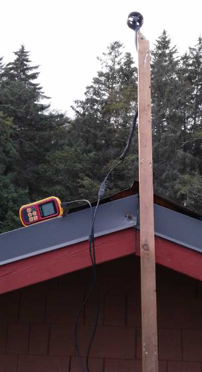 (5th) I got out the wind
meter
and tried out some spots. As I had surmised, the front corner of the
house roof seemed to be the best spot if I wasn't going to erect some
tall tower. I got readings of about 1.8 to 2.2 meters per second. (Of
course the wind is always coming and going. To most fairly compare any
two
spots, one ideally needs two anemometers and a second person on the
cell
phone or 2-way radio.) It seemed best at least 4 or
5 feet above the peak. As I walked along the peak toward the other end
of the roof, it got lower, no doubt mainly because of the tall trees
too close to the other end of the house.
(5th) I got out the wind
meter
and tried out some spots. As I had surmised, the front corner of the
house roof seemed to be the best spot if I wasn't going to erect some
tall tower. I got readings of about 1.8 to 2.2 meters per second. (Of
course the wind is always coming and going. To most fairly compare any
two
spots, one ideally needs two anemometers and a second person on the
cell
phone or 2-way radio.) It seemed best at least 4 or
5 feet above the peak. As I walked along the peak toward the other end
of the roof, it got lower, no doubt mainly because of the tall trees
too close to the other end of the house.
The top of the driveway where the wind funnels in at
ground level (at least for our typical southeasters) was a close
second, just 2 or 3 feet off the ground. Figures might have been 1.7 to
2.1. Everywhere else had too many wind shadows - mostly of trees.
Then it occurred to me to go down to the beach. In the
access path there was again that wind tunnel effect, and I got readings
up to maybe 3.5. Down on the beach itself I was getting up to over 4 -
even a 4.8. (I should probably have walked more toward the water, too,
to be sure I was out of the wind shadows of the trees.) Theoretically
the strip beween the highway and the beach is my property.
Theoretically. Hah! Even if I put the windplant in the path, and
somehow got the power across the highway, everybody uses that path to
drive their "quad" to the beach. A small windplant set up there would
surely be vandalized by annoyed people or stolen.
The front corner of the house roof it is! This also would give the best
chance to try out a venturi to funnel in the air, too, if I got around
to it. Except for the driveway, but that would be in the way.
High Wind Protection
 Occasionally we get some very strong gales here, with
winds over 100 KmPH, maybe up to 120. With wind power increasing at the
cube of the wind speed, this had been bothering me. I wished people had
adopted the Piggott tail vane (rudder) design where a high wind would
swing the propeller away from the wind, as far as edge-on instead of
facing directly into it.
Occasionally we get some very strong gales here, with
winds over 100 KmPH, maybe up to 120. With wind power increasing at the
cube of the wind speed, this had been bothering me. I wished people had
adopted the Piggott tail vane (rudder) design where a high wind would
swing the propeller away from the wind, as far as edge-on instead of
facing directly into it.
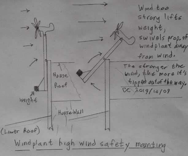
On the 9th I suddenly had the idea to mount the whole
windplant on a pivot with a weight at the bottom. If the wind was
strong enough to overcome the weight, the whole windplant would tip
over. The stronger the wind, the farther it would tip. Since the
windplant pivoted on its own base, with a slip-ring for not twisting
the wires, the tip-over hinge - if the whole thing was to be kept
simple - had to be pointed in one direction (or perhaps could be
bidirectional) rather than being equally applicable regardless of wind
direction. But the strong gales here come from the southeast. We've
only had 2 or 3 bad ("windplant wrecking force") gales since I've lived
here, all from that direction. For those it would work.
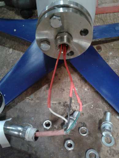 I
also figured out how to attach something to the mounting
flange provided. It looked like the only possibility would be to weld a
piece of pipe to it. But I found a 1/2 inch stainless NPT inside
threaded pipe coupler that seemed to be a perfect fit for the bottom
mounting flange. It was indeed such a snug fit that I had to
laboriously pound it into the hole in the flange with a hammer.
Perfect! - it will never come loose.
I
also figured out how to attach something to the mounting
flange provided. It looked like the only possibility would be to weld a
piece of pipe to it. But I found a 1/2 inch stainless NPT inside
threaded pipe coupler that seemed to be a perfect fit for the bottom
mounting flange. It was indeed such a snug fit that I had to
laboriously pound it into the hole in the flange with a hammer.
Perfect! - it will never come loose.
On the 10th as it was getting dark, it had become quite
windy. I measured at the top of the driveway where it funnels in and
where I have done wind power tests. I got readings of 3-4 meters per
second. Then I went across to the path to the beach and got 4,5,6
meters per second. On the beach that climbed to 7,8,9. As it was low
tide (and with an almost full moon so I could see to come back), I went
way down the beach, far from the trees, and got readings of 8,9,10,11.
Lifting the 7 foot pole as high as I could (making it maybe 12 feet?)
sometimes added about one to the reading, sometimes not. While I wasn't
going to go up on the roof in the dark, I did climb up the ladder and
stick up the pole. From this less than ideal location I got readings up
to 5.5. Since the power is proportional to the cube of the wind speed,
that's 1/8 of the power down at the bottom of the beach. I'm starting
to see the real reason windplants are so often placed just offshore!
(16th) Skipping ahead in the narrative,
in it all I think I found a
wholly better way to protect the windplant in high winds. It works for
the same reason that the propeller starts up so slowly, and gains power
as it gains speed until it is whizzing around with high energy: It
starts up catching only the air near the blades, but as it speeds up,
it starts to catch all the air in the whole area swept by the blades,
catching more and more power.
Usually one aims to find the ideal speed, loading down the
generator just to where it puts out the most power, but without slowing
it down too much so it loses wind - to the 'maximum power point'. If
the wind is too strong, either the high power available overheats the
generator, or else it 'spills' power and instead the propeller speed
becomes excessive, and the unit may fly apart.
But in there I found that if the output is shorted, the
propeller doesn't spin fast at all, even in high winds. It only drifts
around. If the prop isn't spinning, it doesn't catch all the wind in
the circle, just that near the blades. So, the short may make a little
internal heat, but nothing like when it's spinning, and certainly
there's almost no centrifugal force.
Why don't people utilize this as the ultimate high wind
safety mechanism? It seems dead simple. A microcontroller control would
be made to sense that the power output (or voltage of current), or the
generator temperature, is too high, or the frequency coming from the
output is too high (over-revving) and instead of just switching in
another dump load to utilize more power and make more heat, or running
out of options and letting it over-rev, short circuit two or all three
outputs together, perhaps with a solid state relay or two of them. That
will bring the unit almost to a stop and the wind will mostly just go
right by it.
Actual Assembly
 On the 11th I finally got a little done. I took a 7 foot
spruce 2 by 4 that I had milled and cut the ends diagonal (rain runs
off), then I ran my electric hand planer around it and rounded it off
everywhere. Spruce isn't the best choice for outdoors, unpainted, but
that's what I had.
On the 11th I finally got a little done. I took a 7 foot
spruce 2 by 4 that I had milled and cut the ends diagonal (rain runs
off), then I ran my electric hand planer around it and rounded it off
everywhere. Spruce isn't the best choice for outdoors, unpainted, but
that's what I had.
I picked a foot long piece of pipe with an outside thread
on one end to go into the fitting pounded into the mounting flange. I
took an old 3-wire extension cord and cut the plug off it. I slipped it
through the pipe. Then I soldered the three short wires sticking out of
the windplant to the wires of the extension cord, then pulled up the
pipe and threaded it into the coupling in the mounting flange. The cord
now came out the bottom of the pipe. (If you followed all that, you
don't need to look at the picture!)
Then I cut a couple of pieces of 1/8 by 3/4 inch steel bar
for two straps. I sprayed some rust paint on them and then put them in
the kitchen oven for an hour (turned on for 5 minutes for heat) to dry.
With all in place I drilled holes and bolted the straps and the
windplant to the wood.
Then I found that if the wind was blowing from the wrong
direction the propeller blades would hit the back of the 2 by 6. I had
to disassemble it and cut a piece out the length of a blade, making it
a 2 by 5 or thereabouts near the top.
When I picked it up I discovered that the windplant was so
heavy compared to the 2 by 6 that the balance point was only a foot
from the top; in fact, above the bottom of the propeller. It seemed the
high wind hinge would have to be as high up as possible, and it would
still need some more weight screwed to the bottom end of the 2 by 6.
On the 13th I got back to it. I made two aluminum flat
brackets/plates to hold the hinge pin and bolted them to the fixed 2 by
4 upright 'pole'. I cut pieces and screwed this to the edge of the roof.
I screwed a piece of 2 by 6 on horizontally at the bottom
of the windplant's 2 by 6 and a diagonal to stiffen it - something like
the sketch.
I plugged in a plug with its wires shorted together to
prevent the unit from revving up much if there was a breeze. But it was
calm.
Then I got two
neighbors to come and help me
raise it. We
discovered that if the plant pointed "backward" and the pole hinged
over, the propeller blades would hit the 2 by 4 upright. I had thought
they might. But the pole should never tip up unless the propeller is
pointing the other way, so presumably it should never happen.
It was up!
Testing
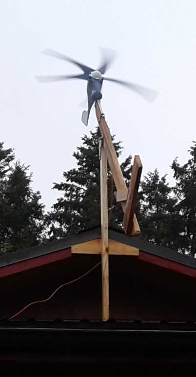 (14th) Early
in the morning it was blowing a storm. I got up and took
down the ladder. (Last time there was a wind it had blown over and
smashed a glass ashtray that had been sitting for ages on the porch
railing. I'm glad it wasn't the patio doors!) I unplugged the short,
and the windplant spun up to high
speeds and the "tilt" mechanism was being activated. It would tilt back
and then come down again with a bang that went through the whole house.
(Well, I did get it from "BangGood"!) When I plugged in the short, it
slowed way down, and stayed tilted up. (I didn't want it to tilt this
easily. It needs a heavier counterweight.)
(14th) Early
in the morning it was blowing a storm. I got up and took
down the ladder. (Last time there was a wind it had blown over and
smashed a glass ashtray that had been sitting for ages on the porch
railing. I'm glad it wasn't the patio doors!) I unplugged the short,
and the windplant spun up to high
speeds and the "tilt" mechanism was being activated. It would tilt back
and then come down again with a bang that went through the whole house.
(Well, I did get it from "BangGood"!) When I plugged in the short, it
slowed way down, and stayed tilted up. (I didn't want it to tilt this
easily. It needs a heavier counterweight.)
I connected a cable with wire nuts and some aligator clip
leeds to the 36 volt kitchen water heater. The voltage between two
phases was about 16 volts AC and the current was around 2.75 amps.
Then I got out a 3-phase bridge rectifier and wired in a
3-prong plug. I soldered the DC output to the same cord and connected
it to the water tank. It didn't seem to give much more: 16 to 18 volts,
2.5 to 3.0 amps. So it would have been delivering 40 to 55 watts to the
water heater. There were lots of sparks when I connected and
disconnected aligator clip leeds.
Then I took the wind meter and got readings in the
driveway and around the house of 4.5 to 7 meters per second. Up over
the roof at the windplant would surely have been in the upper part of
that range if not a little higher.
I had the feeling it was just a bit overloaded. With a
lighter load, the prop would have spun a little faster, and maybe
delivered actually more voltage and hence more current. A little later
I came back and it was just 5 volts. I looked and the unit was spinning
only slowly. Definitely the load should have been reduced, and reduced
more as the wind lightened. I disconnected one wire from the rectifier.
The speed went back up. The DC voltage went up to 12-15. Then the wind
seemed to pick up a little. I reconnected the phase (this time with an
aligator clip - I was getting tired of soldering!) and found the
voltage up to 19 and current over 3 amps. That made to 60 watts.
If I disconnected the water heater the open circuit
voltage ran up to over 50-55 volts DC. Yes, dragging it down to under
20 was surely an overload. Eg: 40 volts at 2 amps is more power than 20
volts at 3 amps.
(This brings up that if I put the third heater element in
the water heater in series with the other two, it would be less load.
This would be useful for the solar on dull days, too. I just need to
put in a switch: all three elements in series (~150 W @ 38 volts), or
short one with the switch and have two as it is now (~240 W @ 38 V).)
How did that power compare with the theoretical? Say 7
m/s, (times 3.6) is 25 Km/hr. I worked out last month that 20 Km/Hr
should be over
60 watts. (25/20)^3 should then be 120 watts. But as I say, it was
probably overloaded and not running at its "maximum power point". And
was the wind really doing 7 m/s? It varied moment to moment. At least
the power was the right order of magnitude. It would however heat the
water a lot faster at 120 watts than at 60. (In the clouds and rain the
1000 watts DC solar was only managing 25 watts, so I wouldn't have
turned the water heater on as the batteries were already low from
leaving it on too late the previous night. Some decent batteries is
obviously a big part of the solution for that.) 40-60 watts was better
than nothing, although it would take several hours to heat the water.
The storm showed every sign of lasting that long. Well, all very fine
for a test and a day's hot water.
Then I decided to rewire the hot water heater. I put in
the switch so it could be switched between 2 heater elements in series
and 3, by shorting one or leaving the switch 'off'. That took the
better part of 2 hours, but the gale seemed still about the same. With
the switch open, readings were now around 2.7 amps, 22-24 volts. So it
lost .3 or .4 amps, but gained 5 or 6 volts. 2.7 times 23 is 62 watts.
I think it was spinning faster.
Wait! I can measure it! I connected the
meter on "Hz" to the AC direct
from the unit:
2 water heater elements in series (heaviest load) - 70 Hz [around 55
watts?]
3 in series (somewhat lighter load) - 75 Hz [over 60 watts?]
No load connected; Open circuit - 100 Hz
I don't know what propeller RPM those figures translate
to, but one can see the relative speeds depending on loading. That
gives us means for figuring out where the maximum power point is. It's
probably found by loading it down to somewhere between 75 and 90 % of
the free running speed.
The gale continued without let up all day. At some point
in the early afternoon I found winds up to 9 m/sec (32.4 Km/Hr) and
voltage around 25-26. That would have been over 70 watts. (I have no
doubt that the winds were considerably stronger in the open, like down
on the beach or just offshore.)
As it was getting dark the plant started banging around on
the safety pivot. It had finally heated up the water to where the tank
shut off, and it had no load. I felt the water and decided to turn it
up higher anyway, so the tank came back on.
The power might have been 15-25 watts more if the
windplant hadn't kept tipping back. Spilling wind was supposed to be
for still higher winds. But I wasn't about to go up on the roof in the
gale and pelting rain to add another piece of counterweight. One could
lose one's balance on the roof in the wind. Or if one's ladder blows
over there's no way to get down. (Well, of course I would find some way
to tie it up.) And in general it would be most unpleasant. The banging
of the windplant against the pivot was somewhat disturbing tho.
The next morning was calm and partly sunny.
I had heard in the evening that the winds had been
supposed to be "up to 100 kilometers per hour". Hmm... It was certainly
a howling gale, but even if the beach and on the ocean was double what
it was near my house, that certainly didn't match what my anemometer
was reading. If it doesn't get a whole lot worse than that, and it was
only giving under 100 watts out of 1200 rated, I don't think the
tip-over safety device is needed. I decided to just screw it closed,
and did so. Soon I realized that shorting the output was a better and
simpler way to protect the unit.
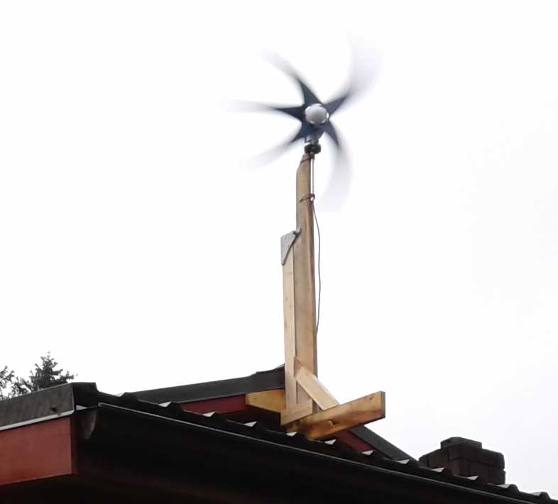 I had heard that molded plastic
propeller
blades aren't very stiff and will bend a little in high winds.
I had heard that molded plastic
propeller
blades aren't very stiff and will bend a little in high winds.
But this is ridiculous!
...of course, it's all a camera trick.
(16th) There was a fair breeze and I connected the windplant to a
250/500 watt electric heater. It read 22 volts, 3/4 of an amp, for a
grand total of around 16 watts. The other (250W) setting didn't work. A
400/800 watt heater didn't work at all. A 1500 watt heater stalled the
windplant. The wind picked up and the figures became 27 volts, .9 amps:
24 watts. (I couldn't get a stable Hz reading.) I caught a gust at 35
volts, 1.12 amps (39 watts). I could feel just a bit of heat from the
heater. Did that make up for having the patio door cracked open to run
the wire in? Probably not!
I started to get the feeling I'd be lucky to ever see much
over 100 watts out of this 1200 watt rated unit. The winds just don't
get that strong. But just twice the wind speed is 8 times the power.
Maybe if I could put it down on the lower beach away from the trees?
Maybe if we start getting those infamous northern hurricanes like on
the Atlantic coast?
Later in the day (after going into town) I reconnected it
and saw it hit 42 volts and 1.6 amps = 67 Watts. An average might have
been 35 V, 1.3 A for 45 W. The heater wasn't hot, but it was warm. Big
waves pounded the beach. Well, at least it was something.
In the evening I tried driving the hot water heater again
but the wind wasn't as strong and it was entirely too much for it. The
blades virtually stalled and it was just a couple of volts at 1/3 of an
amp - less than a watt. Back on the heater it went up to around 25
volts and .9 amps - over 20 watts. If it had had just the right load in
the gale on the 14th, and if the "tilt" switch hadn't been tipping it
away from the wind, it might have been over 100 watts after all.
Nothing like 1200.
Permanent Connection
I didn't want to use the 24 volt charge controller
supplied because my batteries are 36 volts. But if I could count on the
unit putting out over about 45 volts or so, perhaps I could simply
connect the rectified output to the PowMr solar charge controller in
parallel with the solar panels? If its voltage was higher than the
solar, the controller would use it instead.
OTOH if I had ordered the 12 volt windplant, perhaps I
could have used the MPS7210A boost converter to bring (eg) 15 to 30
volts DC to up near 40 volts to charge 36 volt batteries. The voltages
work out better. Well - so far - I'm not planning on getting another
one. If I do I'll try the 12 volt unit. Now that I see this one can
give over 50 volts it seems like a good idea.
The only thing those wouldn't provide was a "dump load" in
case the windplant was spinning too fast and the batteries were already
charged. But the little 24 volt charge controller that came with it
didn't have a dump load either. Perhaps for that, on sensing 55(?)
volts it could connect to a water heater in an uninsulated tank in the
greenhouse? I don't suppose that would do much for the greenhouse. Keep
it from freezing?
The best option would doubtless be a microcontroller based
controller that would decide whether to charge batteries and or
variably turn on dump loads (maybe 3 or 4, one or more as needed, eg
40/80/160 W or 30/60/120/240 W), roughly maintaining maximum power
point output, moment by moment. I'm not willing to create such a unit
in the midst of so many other projects.
And on the 14th in the blowing wind, I wasn't willing to
do much outside work at all. I certainly got it put up on the right
day, calm while working then a gale the next day to test it!
(22nd) I
finally came up with a plan for connecting the windplant. It doesn't
use the 24 volt charge controller that came with the windplant:
1. Run the 3-phase AC from the windplant to the garage with a 3-wire
extension cord.
2. Rectify to DC with a 3-phase bridge rectifier. It seems to be under
35 volts open circuit in a good wind, and it certainly will be under
load.
3. Connect it to an MPT-7210A 'boost' DC to DC charge controller to put
out 39+ volts and charge the batteries, in parallel with the solar
panels and their PowMr charge controller.
This doesn't do the high wind protection by short
circuiting the windplant output. That would have to be handled
separately.
I did the above on the 23rd. It was a windy afternoon (and
getting on by the time I had it done). Readings were around 10 watts.
One could hear the windplant speeding up and slowing down a bit as the
MPT unit looked for the maximum power point. It was probably getting it
about right, not loading down the propeller to a stall, yet not letting
it spin up too high either. Considering it was made for solar and not
wind, that's pretty good.
Later the wind picked up a bit and it was doing 15 watts
or a bit more. Still a disappointing replacement for solar, of which on
this dull day in the later afternoon, 1000 watts of panels were only
yielding 40 watts. In fact I had been unable to get the kitchen water
tank up to temperature. I had been turning it on, and then off again as
the batteries dropped.
I went for a walk on the beach - I've been falling off on
getting exercise - and gaining weight! The rain stung my face and it
was apparent that there was much more wind there. ...double the speed,
as I measured previously? Let's see... double the wind speed is 8 times
the power. So 12.5 watts would have been 100 watts. That amount of
energy would certainly be useful!
I decided that if the
windspeed at the wndplant was only going to be half the speed that the
weather stations were saying, I didn't need to bother with protecting
the plant from high winds. They just wouldn't get that severe where it
was.
Venturi Concept (one more time)
I couldn't put the windplant on the beach where the
highest winds were for several reasons, including that it would be too
much work. The other obvious thing to do to increase the output power
even in lighter winds would be to make a venturi duct to feed wind to
the propeller at accelerated speeds. Inlet and outlet openings just 1.5
times the diameter of the propeller would feed it from 2.25 times the
area.
A 2 meter diameter front and rear would have over twice
the cross section of the 1.28 meter windplant propeller diameter; in
fact 2.44 times. Allowing something for friction losses, if this forced
twice the wind through the venturi, would it not have to travel twice
as fast at the narrowest point, where the propeller would be located?
and thus have 8 times the energy? Would that not be much better than
simply making the propeller double diameter, which would only be 4
times the energy?
I would note that:
1. For a generator the flaring
exit is more important than the flaring entrance. (For an airplane duct
the entry is the more important.)
2. A rounded entry/exit shape (see detail) improves performance,
drawing in or sucking out air more effectively.
3. The best profile for both entry and exit section of the venturi tube
could no doubt be worked out with a computer simulation. I don't want
to wrap my head around that, but if anybody does, please feel free!
Here is the idea, with high wind
protection: a moving top that would blow open to shed wind.
I may never build it because of having too many projects,
but it's the concept.
My
Solar
Power
System
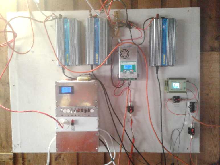 The solar equipment panel in the
garage
(batteries below).
The solar equipment panel in the
garage
(batteries below).
* 3 1KW grid-tie inverters - the AC cords are the outputs.
* PowMr 50+V input buck solar charge controller (39.5V output to NiMH
dry
cells battery).
* New, right: MPT7210A boost solar charge controller with 3-phase diode
bridge, from windplant.
With the surface mount circuit breakers (which enclose all bare wire
ends)
I wouldn't again make a circuit breaker box with panel mount breakers.
The 30x60mm, 24W LED panel light that lights this image from above-left
is plugged into the 36 volt HAT connector socket on the breaker box.
Month of October Log of Solar
Power Generated [and grid power consumed]
(All
times are in PST: clock 48 minutes ahead of sun, not PDT which is an
hour and 48 minutes ahead. DC power readings - mostly the kitchen hot
water heater - are reset to zero daily, while the others are
cumulative.)
Date House solar KWH(Grid+DC), +Trailer Roof solar KWH = day
total KWH
made [power
co. meter readings] weather, usage...
Sept. 30th 96.93+.48, 836.90 -> 9.32 KWH [Finish car chj; BR Heat;
67944@18:30;
Bath] sunny.
October 1st 97.69+.25, 837.43 -> 2.54 KWH [Car 60 Km, chj@3800W;
67969@20:30] heavy clouds & rain. I found the (ground fault)
circuit breaker to the trailer blown, so the 4 panels on the trailer
were off-line for an unknown length of time.
2nd 98.89+.43, 838.66 -> 2.86 KWH [BR Heat; 67980@20:30]
Cloudy.
3rd 103.50+.54, 842.07 - 8.56 [67990@19:00] mostly sunny
4th 108.03+.36, 845.72 - 8.54 [85Km,Chjcar@3800W;
68013@18:30] mostly sunny
5th 111.88+.37, 849.04 - 6.74 [trailer heat; 55KmChj@3800;
68034@19:00] Sun & clouds
6th 113.33+.45, 850.23 - 3.09 [68049@19:30; trailer heat
250W(on from now on for winter)] Cloudy.
7th 116.73+.61, 852.41 - 6.19 [68064@19:00] AM Sunny, PM
some clouds & rain.
8th 120.91+.80, 856.37 - 8.94 [68078@19:00] Sunny! (Frost
early AM - well, it is October! Fairly warm PM.)
9th 123.41+.56, 858.67 - 5.36 [55Km,Chj@3800W; 68104@18:30]
AM sunny, PM mostly cloudy
10th 125.97+.44, 861.53 - 5.86 [68120@18:30] some sun.
11th 126.81+.35, 861.53 - 1.19 [85 Km,chj@3800W; 68150@20:00] Overcast.
Trailer plug got pulled out previous night, unnoticed until I went to
check the solar output. In other news... car went 88 Km, getting 7
Km/KWH, and recharging at 90% efficiency would have used about 14 KWH
recharging. Add 6 KWH for trailer heat, that's 10 KWH for everything
else. The same, 6+10 the day before but without the car. Definitely
consumption is rising for the dark, cold winter, just as solar
production plummets! The solar hot water wasn't hot this day, but it
was certainly draining the batteries when I turned it on. I worked on
the mounting for the windplant.
12th 129.22+.42, 863.89 - 5.19 [55Km,Chj@3800w; 68173@19:00] Some sun
and some rain. So today ~9 KWH to recharge car, 6 for trailer heat and
8 for everything else (including bedroom heat at night).
13th 130.85+.57, 865.91 - 4.22 [68191@19:00] Some sun but more clouds.
14th 131.21+.00, 866.17 - 0.62 [68211@18:00] Horrible, simply horrible!
Howling gale & rain. Dullest day! Winter has struck!
15th 133.00+.47, 867.72 - 3.81 [68227@17:30] A bit of sun, then cloudy,
some rain.
16th 134.33+.39, 868.98 - 2.98 [60Km,chj@3800W; 86253@18:00] Bit o'sun,
rain, clouds and wind
17th 135.50+.43, 870.00 - 2.62 [68269@18:00] Started sunny, but soon
turned to rain & clouds
18th 137.08+.47, 872.15 - 4.10 [68289@20:00] A little sun, & some
rain. 0 KWH for trip to Masset in Toyota Echo... but 52$ for gas - ouch!
19th 139.39+.43, 874.42 - 5.01 [Laundry; 55Km.Chj@3800W; 68316@18:00]
G'day
20th 141.07+.40, 875.95 - 3.61 [15Km,chj@3800W; 68342@20:30] Mostly
overcast.
21st 141.66+.10, 876.43 - 1.17 [55Km,chj@3800; 68367@18:00] Overcast
22nd 1.07+.73, 877.64 - 3.01 [Power fail most of night;
start charge car (2KWH?); 68379@17:00; finish charge car] Mostly
overcast, sprinkles.
23rd 1.62+.34, 878.12 - 1.36 [68405@18:00] wet, dull,
windy. Connected windplant - helped by a few watts.
24th 1.92+.23, 878.35 - .76 [68425@16:30]
Wow! Wetter, Duller, no wind.
25th 3.78+.54, 880.13 - 4.18 [68443@17:30] largely
sunny but a bit of clouds and rain.
26th 5.96+.47, 882.56 - 5.08 [55Km,chj@3800W;
68466@20:00] Sunny!
27th 7.96+.48, 883.87 - 3.79 [35Km,chj; 68492@23:00]
Sunny! (Plug came half way out from the trailer)
28th[PwrFail]+.42,886.57- 5.62 [68505@17:00] Sunny Again! Est. house:
2.5 KWH - blown breaker reset meter)
29th 0.87+.43, 887.18 - 1.91 [68526@16:30] Overcast.
30th 1.47+.32, 887.69 - 1.43 [laundry;55Km&chj;
68560@17:30] overcast.
31st 2.98+.24, 888.72 => 2.78 KWH [68579@17:30]
mostly cloudy, a bit of sun in the afternoon.
November
Solar: House+DC, Trailer - total KWH [grid power meter
reading(s)@time] Sky conditions
01st 4.00+.19, 889.33 => 1.82 KWH [68598@18:00]
light
overcast.
02nd 5.41+.56, 890.50 => 3.14 [55Km.chj.car;
68627@17:00] cloudy AM, sunny PM.
03rd 7.20+.42, 891.87 => 3.58 [68648@19:00] Mostly
sunny.
04th 8.08+.39, 892.65 - 2.05 [68666@17:30] cloudy.
WHAT IT'S THE 4TH ALREADY?
05th 8.79+.11, 893.28 - 1.45 [68684@20:00] cloudy.
Daily-
KWH- # of Days (Oct)
Made
0.xx - 2
1.xx - 5
2.xx - 5
3.xx - 5
4.xx - 3
5.xx - 6
6.xx - 2
7.xx -
8.xx - 3
9.xx -
10.xx-
11.xx-
12.xx-
13.xx-
14.xx-
15.xx-
16.xx-
Monthly Tallies: Generated KWH [Power used from grid KWH]
March 1-31: 116.19 + ------ + 105.93 = 222.12 KWH - solar [786 KWH -
used from
grid]
April - 1-30: 136.87 + ------ + 121.97 = 258.84 KWH [608 KWH]
May - 1-31: 156.23 + ------ + 147.47 = 303.70 KWH [543 KWH] (11th
solar panel connected on lawn on 26th)
June - 1-30: 146.63 + 15.65 + 115.26 = 277.54 KWH [374 KWH] (36V, 250W
Hot Water Heater installed on 7th)
July - 1-31: 134.06 + 19.06 + 120.86 = 273.98 KWH [342 KWH]
August 1-31:127.47 + 11.44+91.82+(8/10)*96.29 = 307.76 KWH [334 KWH]
(12th panel connected on lawn Aug. 1)
Sept.- 1-30: 110.72 + 15.30 + 84.91 = 210.93 KWH [408 KWH]
(solar includes 2/10 of 96.29)
Oct. - 1-31: 55.67 + 13.03 + 51.82 = 120.52 KWH - solar
[635 KWH - from grid]
Egads, here I am again with a late newsletter I'll have to work out the
monthly totals another time, again!
6
month total March 1 to August 31: 1643.94 KWH made; [2987 KWH consumed
from grid]
Things Noted
* On September 30th over 9 KWH was generated. No daily figure in
October hit '9' again even on the sunniest days as the sun sunk down
toward the horizon with long tree shadows reaching everywhere and the
days getting shorter. It's a long way down from 17 and 18 KWH on sunny
days in June (and with only 11 solar panels then instead of 12) or the
several '15's in August. (All-cloudy July we won't talk about.) In
spite of that, collection in September was 2/3 and in October was 1/3
as much as in summer - not a lot, but not trivial.
* After the 10th the collection figures became rather abysmal.
Obviously the panels need to be standing up at a much steeper angle
(than 15° from flat) toward the south. I may remount some or all of
them.
* The time of day I went out and got the day's solar collection
readings got earlier and earlier as the days got shorter.
* We can be sure the shallow slope of the south roofs along with the
lowering sun angle to reduce the sunlight hitting the collectors
combined in reducing the collection. I plan to mount a couple of panels
on a pole at latitude angle to catch more in the winter. I dug out the
old satellite TV post, which had a big concrete footing, dug a new hole
for it in a sunny spot, and got my neighbor to move it there with his
bobcat/forklift. The cement footing was so heavy the back wheels lifted
off the ground a couple of times. (Perhaps I'll put the panels from the
lawn on it? Or
the two old 208 watt, 54 cell panels from 2012? No one seems to want to
buy them at any reasonable price. I'm offering them at a bargain, but
I'm not going to give them away, so I might as well put them up as have
them sit in my cellar?)
* Except when it was fully sunny, I kept turning off the grid ties from
the four 250W panels to feed the DC system with the hot water tank in
the kitchen. They didn't need to be off except when the water heater
was on, but who could remember to keep flipping them off and on? On
dull days the batteries couldn't be kept charged even with them off,
and the water heater couldn't be brought up to temperature.
* 50 watts in dull overcast is just 2.5% of the rated 1000 watt panels'
output. Accounting for the poor angle of the panels, that's about as
dull as full sunlight out by Ganymede & Jupiter (4%). It's still
brighter than at Titan and Saturn (1%), but it could be down there by
December.
* With a starting point of 6 KWH per day to keep the trailer warm,
electric consumption from the grid shot way up over summer levels when
it might only be 6 KWH total and any more was supplied by the solar.
Added to that even on a "nothing" day now were bedroom heat, and then I
turned on the almost 200 watts of LED lights of the indoor LED garden
near the end on the month for 8 to 10 hours a day to grow romaine
lettuce, carrots, onions, and spinach for winter, and to keep the
coffee bushes happy. I brought in tomatoes that were in pots in the
greenhouse, but they didn't look good and died. (I think they were
suffering from drought ever since I went on holidays in August. The
tomatoes still in the greenhouse planted in the ground were still
going, if not producing much.) And on days when I drove somewhere,
consumption rose further. There was no point trying to charge from
solar.
Electricity Storage (Batteries)
Turquoise
Battery
Project:
Long lasting, low cost, high energy batteries
Electrolyte to Depassivate Discharged
Manganese Oxides?
Somehow since the beginning, probably 2008, I had thought
I understood that no state of charge
of manganese oxides was soluble or an insulator, so I assumed MnO2
could always be recharged. I finally read something that indicated
otherwise, that one state of valence 3 - either MnOOH or Mn2O3 (doesn't
matter which one) - became passivated and wouldn't recharge.
This explained otherwise puzzling low capacity and loss of
capacity in so many of my cells! Using discharged MnO2 from old
alkaline dry cells, if it wouldn't charge up this explained why I had
such low initial amp-hours, and why they just got worse after 2 or 3
charges.
But I couldn't believe there was no way around it. The
Polish researchers that mentioned the problem were avoiding it by using
potassium sulfate electrolyte, which (as I surmised with oxalate) moved
two electrons at once and so took the MnO2 (valence IV) straight to
Mn(OH)2 (=MnO, II) with no intervening valence "III" state.
I thought I had a success when I added some potassium
oxalate to the first cell on the evening of the 3rd. It improved the
voltage and current drive. In fact, the cell would now discharge only
very slowly below 1.7 volts open circuit, instead of below 1.6. The
improvement also in voltage under load from less than a gram(?) of this
salt was quite surprising.
But again once the cell was discharged it didn't seem to
get it all back again. By now I figured most of the Mn in the electrode
was at valence 3 and somehow passivated. With a 20 ohm load, the cell
was down to about 3 minutes before it went under 1.0 volts. Pathetic!
In the original first test of this cell, while the voltage had been
under 1.2 most of the test, it ran for almost exactly 2 hours down to
1.0 volts. And here one suspects that already much of the MnO2 was in
the MnOOH state - explaining the low amp-hours of all my cells with
manganese oxide positives.
(4th) The other thing to try to get the MnOOH to recharge was sodium. I
added 1/2 gram of sodium oxalate after lunch. I'd have added more but
it isn't very soluble. That was probably already more than would
dissolve. (I was a little reluctant to try sodium chloride because all
I had was "sea salt" or "iodized", neither of which, by definition, was
likely to be pure.) I put the cell on charge at 1.9 volts. The sodium
oxalate didn't seem to do much, which wasn't surprising considering how
little soluble it is.
So I added 1/2 a gram or so of table salt. (pH remained at
13.) This seemed to have an effect. Upon charging, the discharge times
before dropping through 1.0 volts very gradually started to lengthen: 3
minutes, 4 minutes, 5+ minutes (times 3 tries), and then 6+. With the
cell only drifting lower slowly from 1.8 volts, it also didn't draw
much current at 1.9 volts and so it took a long time to recharge
between tests. (If it's discharging at 60mA and only charging at 8... I
wasn't even sure I was allowing enough time between discharge tests.
Then I thought to add another 1/2 gram of NaCl. By then it
was late. That was it for the 4th. I left it on charge overnight,
seeing it wasn't charging much anyway.
Another thing worthy of note: with not sealing the filler
hole, the cell didn't start leaking again, and likewise the other one
sat idle without leaking.
(5th) In the morning I disconnected the charge and let the cell sit an
hour. It only lazily drifted down from 1.9 volts, saying it couldn't
have been drawing much charging current. It was still at 1.83 when I
connected the 20 ohm load. This time it lasted 7.5 minutes. That was
again an improvement, tho not a large one. It had had all night on
charge, so it seemed it was the cycling that improved it rather than
just the charging. That was about 6.5 mA-H. It was going to take a lot
of cycles and a long time to get to an amp-hour at this rate!
But the important thing was the direction. Where everybody
else apparently has only had manganese oxide electrodes becoming more
and more passivated - as per all my previous results - it was gaining;
depassivating. Having a sodium component to the electrolyte seemed to
be the key.
The day's discharges lasted 7.5, 7+, 8 and 8.5 minutes. Very
gradually longer. And the charging was so slow I wasn't always sure I
was putting more in than came out during the last discharge. I thought
of raising the charging voltage from 1.9 volts, but it wouldn't be good
to be charging MnO2 to permanganate, KMnO4. (Considering how long it
took to drift down from 1.9 to 1.8 volts when the charge was removed,
was it already charging to permanganate? Yet it fell to about 1.55
volts almost instantly when a load was connected.)
Might we then presume that if the mix started out charged
to MnO2, the presence of the sodium would prevent it from passivating
in the first place? So, if instead of putting the (mostly discharged)
MnOx electrode directly into the cell, putting it in some bleach first
would chemically charge it to MnO2, whatever state it came out of the
old cell in - and electrically passivated or not.
Bleach (NaClO), on giving up its oxygen to oxidize
the Mn to MnO2, would doubtless turn into salt, NaCl. Now NaCl is an
intended ingredient of the electrolyte, so any remnant after draining
and rinsing was probably okay. (Did it even need rinsing? How pure is
the bleach? I guess it needs rinsing in case of unreacted bleach.)
I decided that rather than form electrode bricks and
bleaching them, I would just bleach the powder and lumps straight out
of the old dry cells, in plenty of bleach. That would hopefully ensure
that it would be starting out as fully charged MnO2 when I made the
bricks. And it would mean that the cell would start out with both
electrodes already fully charged. Perfect!
(Let's see... I read in somewhere where MnO2 was bleached
in NaClO, but they also added KOH to the mix. What was that for?
Perhaps just to ensure it was alkaline. Wouldn't want "Mn++" ion
dissolving out in acidic solution! First I thought I should add a bit
of KOH too. Then I remembered the dry cell mix is already full of it.
So just diluted bleach then!)
Well, I started out in 2008 thinking that while starting
without knowing too much might cause me trouble, but without having the
same preconceived ideas everyone else had, without "knowing" battery
details that everyone who was educated in the field did, I might come
up with something new. It certainly didn't think it would take almost
12 years (not that I hadn't already come up with, at least, charging Mn
to metal in water for a highest voltage negative electrode), but here
is something. I thought MnO2 electrodes were said to be short lived
because they get overcharged to MnO4- and dissolve. It didn't seem to
me this was insurmountable. But everyone in the field probably "knew"
that MnO2 passivates on discharge and that that is the cause of its
short cycle life. And so they passed it over in their search for a long
lasting positive electrode. I didn't know, so I tried it. And in spite
of all my misunderstood problems with it, I've now found a way to make
it work. And maybe the nickel manganates idea, too.
(Well... it soon seemed it wasn't really working after all.)
Air Leaks?
(6th) After charging all night, the cell was still drawing over 7 mA,
whereas after the previous night's charge it had been down to almost 3.
When the charge was disconnected, the voltage dropped pretty quickly
into the 1.7 volt range instead of drifting very slowly down from 1.9.
A load test ran for a mere 3 minutes before dropping through 1.0 volts.
What was different? Why had it deteriorated like that?
A possible answer was staring at me. I had decided to top
up the liquid with 1 cc of water. And I had left the filler cap off,
that little bit of modeling clay. Was enough air getting into the cell
through that tiny filler hole to reduce its previously improving
performance? Theoretically oxygen would spontaneously discharge the
zinc. AFAIK it shouldn't affect the MnO2 side. But if it was the MnO2
side that was low on capacity, why would reducing the zinc side a bit -
or even a lot - cause any noticeable performance drop?
I placed the cap back on (careful not to make it really
airtight and cause pressure buildup and leaks), and put the cell back
on charge.
Well... It didn't help. Apparently MnO2 by itself really
isn't a good rechargeable electrode substance. That takes it back to
trying to get good results from nickel manganates.
Bletch
I did a bit more reading. Another researcher thought that
the discharged manganese oxide "sloughed off" the electrode,
electrically disconnecting it and so making it unavailable. That was
different than "becomes an insulator". Does
somebody know the actual reason and others are ignorant like me, or is
everybody just
guessing?
And yet this makes a certain amount of sense: If MnO2
discharges to Mn2O3, an oxygen atom has left the space, so what's left
is less dense. If on the other hand it discharges to MnOOH, just a
hydrogen has been gained instead and this wouldn't apply. Mn3O4 loses
still more oxygen, but the final product Mn(OH)2, one expects would be
hardly
different density than MnO2.
Rather than simply abandoning a cell that didn't seem to
charge, I decided to put in a little bleach and see what
happened. (1/2 a cc.) That was after all what I now wanted to do with
all the MnO2 before putting it into batteries. As it was now late, I
left it idle overnight. It didn't seem to have any notable effect. I
put it back on charge.
I had to confess that I couldn't seem to get the manganese
to recharge to MnO2 by any simple technique or salt I had tried.
Nickel Oxides Electrode
(14th) That being the case, and having had (so far) poor performance
trying nickel manganates, perhaps it was a good time to go back to
something known to work and proceed from there? That would be nickel
oxyhydroxide in pH 14 alkaline solution. But even there, I had used the
bits of NiOOH electrode from a commercial dry cell. It would be going
another step to make my own electrodes. A pretty safe step, one
expects, but it needed to be verified.
Making NiOOH
Supposedly one can 'pre-charge' Ni(OH)2 to NiOOH with
bleach. But I looked at the Japanese patent again and saw they also
added sodium hydroxide to their bleaching solution. Why? Of course!, if
the nickel will only stay charged at pH 14, then the oxygen would
bubble off without the NaOH. (I remember seeing a nickel electrode
bubbling from a decade ago. Was that from bleach at neutral pH and then
the oxygen bubbled off, or from hydrogen peroxide to DIScharge it?) But
they said they washed it with water afterward, which would have put it
in neutral pH water. Perhaps my theory is off-base. Nevertheless I
proceeded to do it their way.
I only had 6% bleach, so I added less NaOH, too. Next they
heated it to 60°C and added the Ni(OH)2, and kept it heated with
agitation for an hour. My God!... I actually bought a lab electric hot
plate with magnetic stirrer this summer - I figured I'd want it for
something! I could actually do it, the same way, instead of doing some
workaround stirring it on the kitchen stove! I did so.
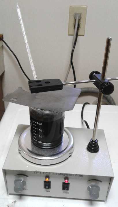 I
poured in 20 grams of turquoise-green Ni(OH)2. It
started to darken immediately and was soon black. Presumably it was
already NiOOH, but I decided to heat it and stir it for an hour per
directions. (What if just a little had turned black and it made it all look
black? A bit of conductive carbon black had turned a whole jar of
bright yellow
paint jet black.)
I
poured in 20 grams of turquoise-green Ni(OH)2. It
started to darken immediately and was soon black. Presumably it was
already NiOOH, but I decided to heat it and stir it for an hour per
directions. (What if just a little had turned black and it made it all look
black? A bit of conductive carbon black had turned a whole jar of
bright yellow
paint jet black.)
After the hour I had
trouble filtering the NiOOH
(presumbly gamma form NiOOH) out of the liquid. (Next I must get some
proper lab filters and filter papers.) But I found that the black
precipitate slowly settled to the bottom. Then the fluid could mostly
be poured off without losing much. I then refilled the beaker with pure
water and repeated.
I figured the bleach and hydroxide would be pretty diluted. Anyway
bleach would become salt (NaCl) and sodium hydroxide was also good
electrolyte. I couldn't see that they would do much harm if there was
only a little left. (Slightly nervous about the salt.)
Then I put on some heat under the beaker and left it quite
a while at 60°C. It got a lot drier. I turned it off for the night,
but dried it some more the next morning (15th). It started to get a bit
crumbly. It weighed 37 grams. I had only put in 20 grams of Ni(OH)2, so
the rest must still be water? I added over 2% (.5 g) of Sm2O3 and over
5% (1.25 g) of conductive carbon black, having decided to assume it was
still about 20 grams of NiOOH. (The Japanese patent said "acetylene
black", but I think that's just a different name for "conductive carbon
black".) Then I added a few drops of the dishsoap 'sulfonates gel'.
The next step was "mixing for 1/2 an hour in a kneading
machine." I didn't have one, so it was in a mortar and mostly with a
teaspoon - the pestle mostly just made it jam up against the glass, and
it was too stiff to squash it from there, so it couldn't do much
kneading.
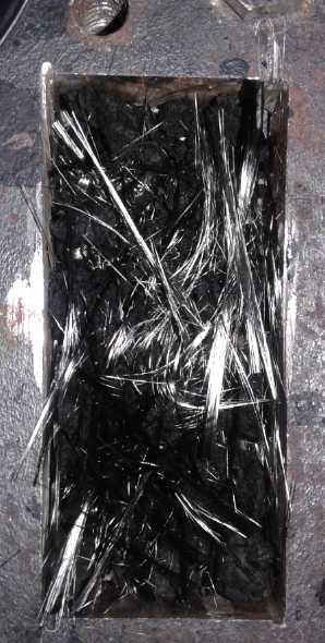 It still wasn't dry dry, but had the consistency of a
stiff modeling clay. I separated some fibers from the carbon fiber
cloth and put them into the bottom of the compactor die. Then I
crumbled some bits of the NiOOH mix and dropped them on top. Then two
more layers of fibers and crumbs. I took it out to the press, but I
didn't get much pressure up before curlicues of paste started oozing
out every crack. Perhaps if needed to be drier? Then again it was
already a pretty solid paste. It was about 4 mm thick.
It still wasn't dry dry, but had the consistency of a
stiff modeling clay. I separated some fibers from the carbon fiber
cloth and put them into the bottom of the compactor die. Then I
crumbled some bits of the NiOOH mix and dropped them on top. Then two
more layers of fibers and crumbs. I took it out to the press, but I
didn't get much pressure up before curlicues of paste started oozing
out every crack. Perhaps if needed to be drier? Then again it was
already a pretty solid paste. It was about 4 mm thick.
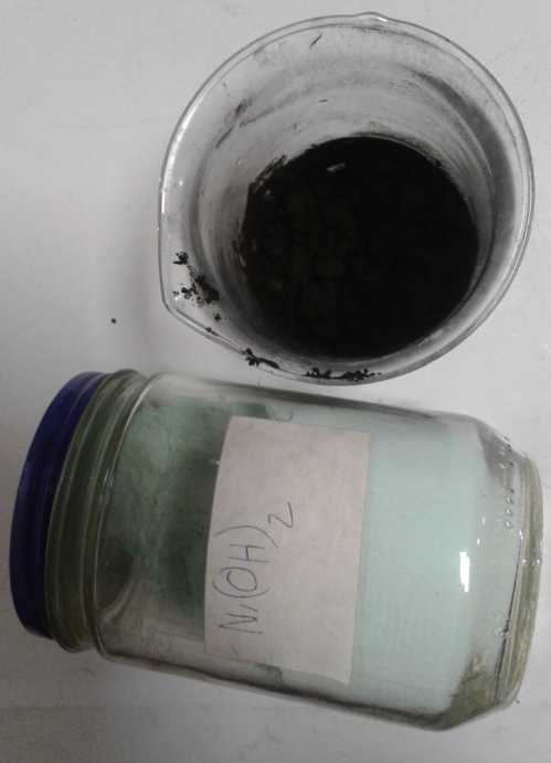 Turquoise nickel hydroxide
converted to black
nickel oxyhydroxide.
Turquoise nickel hydroxide
converted to black
nickel oxyhydroxide.
I hoped to not have to make a new zinc electrode and case,
so I took the first case and managed to slice it open with a knife. I
decided to go with something that worked - at least it did with
manganese, but it has a lower reaction voltage than nickel - and made a
graphite foil current collector. Instead of just
a strip, I cut a piece to fit under the whole electrode, still with a
12mm wide tab to the terminal. I scoured the contact surface with
scotchbrite, then for good measure scratched it up with sandpaper.
I took two chances with experimental things at once. The
manganese
oxides electrode had charged and held its charge (as much as it was
going to) with the dishsoap gel in the mix, so I added that. Then, a
cupro-nickel current collector would have been sure to work, but only
in pH 14 alkaline electrolyte. If I used graphite and it worked
(presumably!), I could later try changing the electrolyte from
alkali to lower pH alkali-salt and see if that still worked, or if that
made the higher voltage NiOOH spontaneously discharge itself. So
hopefully one cell would do two experiments - nickel in alkali and then
nickel in salt.
I removed the piece of separator cloth because its fibers
stuck out. Perhaps that's part of the reason it leaked? It still had
the separator grille, which should be plenty, and even that was jelled
with agar for added protection against shorts. I put everything in
place and closed it up.
Initial voltage was under a volt. I used an eyedropper to
add potassium hydroxide until it came up into the top chamber. then it
was still only 1.12 volts - didn't seem like much for a "pre-charged"
cell. I followed the wires and it was connected to the power supply,
which was unplugged. If it's not on, it acts as a load instead of a
supply. With that disconnected, the voltage slowly rose past 1.3.
Then I got the charge power connected, and the cell just jumped to 1.9
volts drawing only 20 milliamps. Ugh! What could be the problem?
It smacked of an electrode with poor conductivity. I had a
feeling I should have dried the nickel electrode further and compressed
it much harder. But why should it need charging anyway? The nickel side
was pre-charged to black oxyhydroxide, and surely the zinc side wasn't
far discharged?
After a couple of hours of this slow charge, the cell
would still only put out 130 mA if shorted, dropping to 80 after 10
seconds. With a 20 ohm load the cell immediately dropped under a volt,
delivering around 40 mA. Worse... a puddle began to form. The cell
leaked. Ahrg!
Rather than try to fix the leak immediately, I decided to
disassemble the cell, let the nickel electrode dry out better, and then
compact it better in the hydraulic press.
(16th) Rather than wait for the electrode to dry, I had only used half
the NiOOH mix. I made another one with the other half. It seemed much
drier than a day earlier, notwithstanding that I had plunked a little
plastic cup over the top. It crumbled more easily into smaller pieces.
Better Technique
After again doing two alternating layers of carbon fiber
and electrode mix, I had the thought that it might be better to put
some carbon fiber right into the mix, and "knead" it all in one. If it
was well mixed, the fibers should spread out in three dimensions, and
they would be better bonded to the electrode material even before
compacting. So I put some into the remaining mix and mixed it all up as
best I might without going to a lot of trouble. It seemed better. The
fibers weren't moving around free but had mix clinging to them. And
then I didn't need to use the tweezers to spread the fibers apart and
make layers - just put the mix into the die.
In the Polish rechargeable manganese-zinc battery making
project they had used
some sort of advanced and extremely light "graphite foam" (I forget the
name). I suspect the graphite fibers are just as good. And they're
cheap and (with this technique) easy to work with.
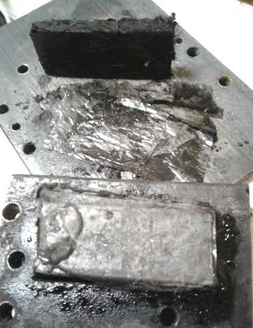 But dry as it
seemed, in the press the mix surprised me
again, oozing out around the edges as soon as there was much pressure
on the punch. I would say it took more pressure this time before that
happened. But my little pieces of plastic/cellophane (to keep the
electrode from sticking to the metal parts) were soaked and everything
just around the brick looked quite wet. And it was still 5 mm thick - I
was hoping for about 4 or less and I wanted to put a few tons of
pressure on it to make sure the particles were well connected together.
I peeled off the pieces and set the brick on edge and on the woodstove
to dry further.
But dry as it
seemed, in the press the mix surprised me
again, oozing out around the edges as soon as there was much pressure
on the punch. I would say it took more pressure this time before that
happened. But my little pieces of plastic/cellophane (to keep the
electrode from sticking to the metal parts) were soaked and everything
just around the brick looked quite wet. And it was still 5 mm thick - I
was hoping for about 4 or less and I wanted to put a few tons of
pressure on it to make sure the particles were well connected together.
I peeled off the pieces and set the brick on edge and on the woodstove
to dry further.
Before bed I put it back in the die and pressed it to 9
tons -- and down to 3 mm. That was more like it!
(17th) I pried apart the cell. It was
surprisingly easy compared to the
first time. I dumped out the old nickel 'brick', which seemed more like
mush, and put in the new one. I cleaned all around the edges and did
everything possible to ensure there were no leaks. It was a fiasco! Not
only did it leak like a seive, but there was almost no current - a
milliamp or two on charge, and just 13mA discharge. This obviously
wasn't going anywhere.
I decided I simply had to print a new case and pried it
apart again. (Getting easier each time.) Black goop was dripping from
the electrode. It wasn't completely mush, but it had swelled up and the
surface had loose particles that were washing off. I had compacted it
well. The Japanese patent hadn't mentioned it, but obviously a nickel
oxyhydroxide electrode needed some sort of binder to hold it together.
CMC gum (sodium carboxy methyl cellulose) or VeeGum (a
'bentonite clay'), might be typical. But I was using the dishsoap as a
gel? Of course the dishsoap was mostly liquid. It had to be pretty
dilute. Probably with just a few drops, which quantity I had really
selected so it wouldn't add too much liquid to compact the electrode, I
wasn't adding anything like enough of the sulfonates gel.
I put the substances of the two electrodes back into the
mortar and then added a whole cc of the "Lemon Fresh Sunlight". Then I
"kneaded" it for a while by hand (mortar, spoons, pestle) to mix
everything together - this time including the carbon fibers as well.
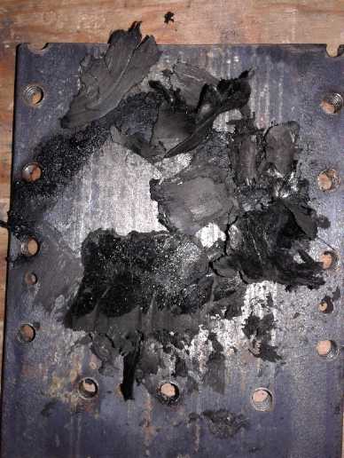 Then I
left it all to dry out again. I had lots of other things
to do. In the evening it was much drier and could be crumbled into
small lumps to drop into the die, but again it surprised me and oozed
out around the mold when I tried to compact it. At about 5 tons I
glanced down and saw that the punch was all the way to the bottom, with
most of the material having oozed out.
Then I
left it all to dry out again. I had lots of other things
to do. In the evening it was much drier and could be crumbled into
small lumps to drop into the die, but again it surprised me and oozed
out around the mold when I tried to compact it. At about 5 tons I
glanced down and saw that the punch was all the way to the bottom, with
most of the material having oozed out.
Paste Electrodes?
I had certainly "kneaded" the material very well in this
process. It gave me the idea that something like this (but automated)
was the way to do the kneading - the thorough mixing and blending of
the
electrode substances. I scraped the material back into the die and
pressed it again, but this time only to 2 tons. At that pressure it
didn't ooze out. But the brick now looked much the same as with 9 tons:
it was only about 3 mm thick. Apparently then it was "fully compacted":
the compaction of the material was in the kneading. And the graphite
fibers were well incorporated and probably pretty well dispersed within
the electrode.
Then I started to think that maybe that was a better way
to make the electrode anyway: knead the substance and then extrude it
under pressure into a mold. I have heard the name "paste electrode"
before (along with "powder" and "sintered" electrodes). Obviously the
moisture content would have to be carefully controlled - it has to be
almost dry, not have enough moisture that one is trying to compress a
liquid. And yet enough for it to flow, if only under great pressure,
from the kneader/extruder into the mold.
With this technique I could see filling molds for large
electrodes - for my "full size" cells - without excessive pressure.
Maybe 10 tons or less instead of increasingly huge as the area to be
compacted was increased. Much more practical!
Later I remembered that I should be able to measure the
volume and weight of the electrode and calculate its density. IIRC a
nickel oxides electrode should be around 1.8 to 2.2 g/cc. If it was
below that, it wasn't compressed enough. That would be a good check on
compaction for next time.
3D Printer Insulated Surround
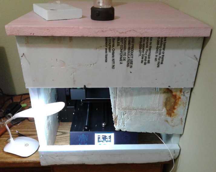 (18th) I cut
some extruded styrene foam sheets to make a housing so the
air around the 3D printer could be heated for printing ABS. I wasn't
really sure that's how I wanted it, so I didn't glue the pieces
together. I stuck in a few nails to hold it in place. The "front"
wasn't much, but it left me room to insert the SD card with the
designs, and blow hot air in with the hot air gun.
(18th) I cut
some extruded styrene foam sheets to make a housing so the
air around the 3D printer could be heated for printing ABS. I wasn't
really sure that's how I wanted it, so I didn't glue the pieces
together. I stuck in a few nails to hold it in place. The "front"
wasn't much, but it left me room to insert the SD card with the
designs, and blow hot air in with the hot air gun.
Then I printed another battery case. The front (top of
cell), nearest the heat gun, lifted. But the back (bottom) stayed put.
Apparently I actually had the front too hot, as it was very
soft and pressed back down to the touch. Of course, after 15 or 20
minutes into a 35 minute print, one is reluctant to experiment with
different settings, or seeing if the heat gun really needed to be on
continuously.
It also occurred to me why the old RepRapPro printer might
have printed ABS so much batter than the new one: It extruded coarser
filaments. They would probably have been stiffer when the next layer
was printed on top, holding the shape better. (A coarser 3D printer was
better?)
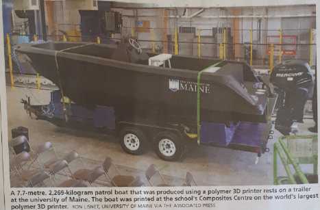 Just for whatever, here's a large
boat printed
by a really big 3D printer.
Just for whatever, here's a large
boat printed
by a really big 3D printer.
Next New Cell (Nickel-Zinc with
graphite current collector)
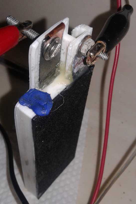 (20th) In the
evening I finally got back to it. The NiOOH electrode was
only about 3 mm thick and the space for it was over 4, so in order to
keep it from swelling up I put in two extra separator grilles, cut down
a bit to fit. Then I put the old zinc electrode on top and put the case
together. This time I went around the outside edge with a strong
magnifying glass. I found some spots that might not have been sealed
and a couple of definite gaps. Apparently I needed to push the pieces
together strongly instead of lightly after applying the solvent/glue. I
redid it until I was satisfied that at least it didn't look
like there were any leaks. I just put in a couple of eyedroppers of
water to keep the electrodes moist because it was late. I had noticed
the nickel electrode turning a light color around the edges as it
dried. That probably meant the NiOOH was revertlng back to Ni(OH)2.
(20th) In the
evening I finally got back to it. The NiOOH electrode was
only about 3 mm thick and the space for it was over 4, so in order to
keep it from swelling up I put in two extra separator grilles, cut down
a bit to fit. Then I put the old zinc electrode on top and put the case
together. This time I went around the outside edge with a strong
magnifying glass. I found some spots that might not have been sealed
and a couple of definite gaps. Apparently I needed to push the pieces
together strongly instead of lightly after applying the solvent/glue. I
redid it until I was satisfied that at least it didn't look
like there were any leaks. I just put in a couple of eyedroppers of
water to keep the electrodes moist because it was late. I had noticed
the nickel electrode turning a light color around the edges as it
dried. That probably meant the NiOOH was revertlng back to Ni(OH)2.
(21st) I filled the cell with 20% KOH. It started out at just 1.1xx
volts, but was very gradually rising. That didn't seem like much for a
supposedly pre-charged cell. I left it 1/2 an hour and it rose to 1.740
volts. Hey, that was more like it! But in another 1/2 hour it had
dropped
to 1.730.
In spite of all my efforts to make a highly conductive
electrode, when shorted it only put out 60 mA, dropping rapidly to 40,
and only drew 4 mA on charge, rising to 1.92 volts without resistance.
I upped the voltage to 2.0 instead of 1.9. That at least got it up to
13 mA. I decided to leave it there.
In a bit I shorted it again and got 170 mA. Maybe it
wasn't a writeoff after all! Again it's puzzling that a cell that's
supposedly pre-charged should need charging before it would do much of
anything.
Then I checked the pH. It was only 13 instead of 14. With
my already weak solution, plus the already soaking with water zinc
electrode, plus a couple of cc I had added to keep the plus side moist,
the electrolyte was too dilute. I started adding flakes of potassium
hydroxide with tweezers, seeking out the smaller flakes that would fit
through the tiny filler hole. It was tedious. The pH strips finally
started looking a little darker... 13-1/4? The charging current went up
from 13 to 15 mA. 13-1/2? 13-3/4? Current was up to 17 mA. When shorted
it put out 250 mA. It started staying above 1.8 and then 1.9 volts for
a minute or two when taken off charge. This was at least starting to
seem more like it. Time to try a longer charge, an hour or more, and
see what would happen.
I checked my KOH solution in the jar and found it wasn't
much over pH 13 either. I wanted to leave 'room' for adding salt to the
electrolyte later, so I didn't want it too concentrated. OTOH the first
test was about making sure 'traditional' nickel-zinc with pure alkaline
electrolyte worked with my own (jelled) electrodes.
After 3 hours of charging the cell was starting to look
pretty decent. Taken off charge it almost immediately dropped to about
1.895 volts... and drastically slowed there. With a 20 ohm load it took
almost 4
minutes to drop to 1.0 volts. After another 2 hours charging current
(at 2.0 volts) was up to about 30-40 mA. Could there be an
internal short? Nope. Taken off charge it sat just below 1.9 volts.
When shorted the cell hit .47 amps and was still at .26 after ten
seconds. With a 20 ohm load it took 6-1/2 minutes to drop to 1.0 volts.
It certainly didn't behave as if it had been 'pre-charged'
before assembly. Oh well, it was working! Of course it wasn't good
enough yet and I hoped and prayed it would continue to improve.
Most gloriously, the piece of tissue underneath the cell
remained dry.
(22nd) The 20 ohm load time (with cutoff
at 1.0 volts) rose from 4 to 6.5 to 8 to 10 to 13 to 18 minutes on
successive load tests. Voltages under load gradually rose and the
voltage snapped back more swiftly and strongly after each test. It
seemed like awfully slow improvement from under 5 to 17 milliamp hours,
but at least it was going in the right direction and continuing that
way. It held more voltage longer when taken off charge, but it still
seemed to lose a lot of charge over a few hours. That too is doubtless
improving. But will it eventually get up to at least 200 milliamp-hours
and hold most of its charge overnight, with nothing funny happening to
kill it? It has a long way to go. And certainly far more charge has
been put into it than comes out of it, so it would seem it only
improves with cycling, not simply charging.
(23rd) Discharge time for running a load seemed to have plateaued at
under 20 minutes. But things weren't entirely static. Momentary short
circuit current finally rose from 1/2 amp to 3/4 and I saw a .82 before
bed, and longer shorts (after 10 seconds) held .25, .29, .33 and then
.35 amps. Charging current had previously stopped falling at about
20-30 mA with a 2.0 volt charge. Now it didn't fall below 40, and even
50 by night. To get less I had to turn it down to 1.9 volts. With a 1.9
volt charge, discharge lasted a minute or two less than with 2.0. How
well would it hold charge overnight? I hated to look.
(24th) As I feared 10 hours later it was down to 1.698 volts. I dumped
out the electrolyte (a dribble or two) and filled it with distilled
water. After waiting a bit, I dumped that, and repeated for 3 total
rinses. Whenever I dumped the cell, quite a bit of black powder
(+trode) came out. In the last minor variation of the cell I had left
an open space at the top. (It was easier to put in the current
collector sheet and tab without damaging it.) I guess electrode powder
was breaking loose there, but some of it was fine enough to have come
through the three grilles, too.
Next cell: narrower space for the electrode so it only
needed one grille, print the grille at a bit higher temperature, make a
little piece to block the gap, and maybe strengthen the dishsoap gel a
bit more. (Even tho it's probably a source - or the source - of the
impurities causing the self-discharge.)
I strengthened the KOH solution a bit, adding 4 grams of
KOH to what would have been 57 grams of water and 11 of KOH. 57+15=72;
72/57=1.26 sg. Still not very strong per most batteries, and still only
a little over pH 13. But I left it like that. Performance wouldn't be
great, but if it held charge better, I could then say "it works".
Then I would try adding salt(s) without again draining the
cell.
After 2 hours of charging, I could tell it was better.
Current had dropped to 30 mA instead of 40, and when I disconnected the
charge it took 10(?) seconds to drop from 2.017 to 1.900 volts instead
of 2. Then it got worse again, as I could see from the same effects,
and the charging current went back up to 40. I could see bubbles
inside. No doubt the gas was carrying up particles. Furthermore it had
somehow developed a leak. Was it the manipulations, or had I put the
plug in the hole too hard and it built up pressure? I ran a load
test with 33 ohms instead of 20. Aside from lasting 33 minutes instead
of 17 or 18, it seemed to be pretty similar to previous tests.
Overnight it held to 1.742 V for 5 hours (up to pee
anyway), 1.734 V for 9, 1.727 V after 11, and 1.715 after 15-1/2 hours.
Better than the previous night but nothing like great.
Then again, I was attempting to make a "typical" nickel
oxides electrode, other than gelling it. One thing I didn't do was to
briefly torch the surface of the electrode to 'sinter' the surface
particles together. That might have eliminated most of the 'crumbs'
coming loose and probably still some swelling of the electrode, which
both doubtless contribute both to poorer performance and to increasing
the self discharge.
(28th) In the evening I got some methylene chloride and smeared around
the joins. then I added a little electrolyte. It still leaked. It
seemed to be in a lower corner on the seamless side. In the morning
(29th) I smeared some of the solvent around everywhere, concentrating
on that corner. Then I eyedroppered in some 20-20 electrolyte. (100 cc
water, 20 g KOH, 20 g KCl - SG 1.4.)
When I hooked up the meter it read 1.742 volts steady. Not
only was the salt not causing self discharge, but the leaking cell had
held good voltage overnight without a big charge beforehand. I
connected the charge at 2.0 volts.
The cell still leaked(!), this time in another corner.
Probably the solution is to increase the extruder temperature for the
3D prints of the cases so the strands of plastic fuse together better.
And to download and install the proper printing "slicer" and G-code
maker for the new printer. (Cura? IIRC.) This should be more feasible
now because on the 27th my new internet connection was hooked up.
Late on the 29th I was rereading this article and was
reminded from near the start of the month that potassium oxalate had
not only worked but had upped the current drive with the MnO2
electrode. Would it similarly help with NiOOH? As the cell was leaking
anyway, and being charged, I added in a dropper of KC2O4 solution.
Unlike with manganese dioxide, it didn't seem to make any difference.
The next time I tried seeing how long it held charge, it
stayed above 1.76 volts overnight, over 1.74 for over 10 hours, and
1.70 for 25 hours. If not satisfactory, at least that was improvement.
The next electrode was going to be a mix of new Ni(OH)2
and MnO2 from dry cells. Now I can either torch (surface sinter)
another purely nickel oxides one, or do both at the same time. The
first is more illustrative of the torching effect. The second, two
experiments at once, is faster progress toward what is expected to be
the desired outcome. I suppose the first is the way to learn more.
The better a cell performs, the more tedious the tests
become. I start to think more and more of a microcontroller unit for
automatically cycling cells over and over and logging the performance.
Honda NiMH Hybrid Car Batteries
(17th) I had mentioned many moons ago
(May, TE News #132) the idea of
arranging the Honda hybrid car batteries I had acquired at least 3
years ago if not 4, into five rows of six tubes each, with each tube of
six cells having a nominal 7.2 volts.
That would put 6 parallel columns of 5*6=30 cells each in
series, giving a nominal 36 volts, the same as my other cells. It got
around the awkwardness of each welded tube being 7.2 volts instead of
6, and hence being unable to make any lesser voltage work out with
other cells and other configurations.
If we assumed the cells were 6.5 amp hours, then the six
columns would total 39 amp-hours. 39 AH * 36 V = 1.404 KWH. If it
actually worked that was probably substantially more storage than my
even older Tenergy NiMH "D" cells. I had my doubts. If some dry cells
were way down in capacity, might the others not be just about as bad?
That was a good part of the reason I hadn't bothered.
But after all they were a different manufacturer. Maybe they'd be
better?
But back then, I had 3D printed some supports/spacers that
would enable doing that, along with some for my other battery tubes. I
had simply never put them together. I had however charged up the
batteries. They were now at the bottom edge of 'won't corrode away',
about 1 volt per cell (just 31 volts for 30 cells in series).
And recently I had run across something I needed: #10-24
threaded rod. I had some when I moved up from Victoria but had lost
track of it, and then I had found no one sold them here. (I could get
1/4" or
larger, but no one seemed interested in bringing in any that was
smaller. I had printed the plastic pieces for #10 and would have had to
redo them for 1/4".) It had seemed like
a stupid little thing to bring an almost done project to a stop, but it
did.
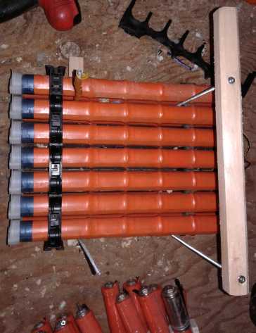
Now I cut some threaded rod into four 10 inch lengths, cut
four pieces of wood for it, and put the mountings together. Then I
wired them up. I disconnected the other batteries from the charge
controller and connected it. By then it was evening of a dull day, and
the PowMr controller was only putting out 20 watts. The voltage rose
from 31 alarmingly fast and hit the programmed 39 volts well within an
hour. That sure didn't say much for the capacity. Less than 20
watt-hours from about 70 pounds of batteries? I think my own marginally
successful battery experiments
worked better than that!
(Oops, I didn't get a picture of the white printed plastic supports!)
Piles
of
NiMH
Dry cells - none of them with a lot of capacity
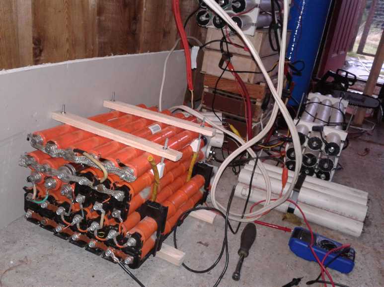 Perhaps the
best that could be said was that at
last I had
done it, and got the batteries off the shop floor, out from underfoot.
And seemingly it reinforces the view that old dry cells seem to dry out
and don't work well any more, so that if one wants lasting cells, they
should be fillable. I wonder if it's worth harvesting the nickel oxide
material out of old NiMH and NiCd dry cells? What I've found so far is
that their cans are much thicker and tougher than those of MnZn 'throw
away' cells. (to take the pressure of overcharging without bursting.)
Opening one with the pipe cutter was hard slogging. One
would want some automated process.
Perhaps the
best that could be said was that at
last I had
done it, and got the batteries off the shop floor, out from underfoot.
And seemingly it reinforces the view that old dry cells seem to dry out
and don't work well any more, so that if one wants lasting cells, they
should be fillable. I wonder if it's worth harvesting the nickel oxide
material out of old NiMH and NiCd dry cells? What I've found so far is
that their cans are much thicker and tougher than those of MnZn 'throw
away' cells. (to take the pressure of overcharging without bursting.)
Opening one with the pipe cutter was hard slogging. One
would want some automated process.
Two
Lithium
Battery
Charger
Circuits:
for AC and DC Power
My NiMH 'D' dry cells having turned more or less to crap
(very low capacity) after just a
few years,
I wanted to put my lithium batteries into the solar power system, but
they just aren't self-balancing. One cell will be fully charged first
and its voltage will rise and rise. Another cell in the string will
refuse to rise above 3.3 or 3.4 volts even when charged. Cells held
above 4.2 volts are in danger of failing, perhaps catastrophically.
Hence all the "battery management systems" and "excess voltage shunt
boards" to keep them happy.
What seemed to be needed - seemingly to me a no-brainer -
was a separate charger for each cell, about 3.6 volts until charged, or
about 3.35 volts for continuous daily solar trickle charge. Each
charger
would sit bolted on top of its own battery in place of the power
wasting voltage shunter boards that often adorn them. What was needed
for a string of cells in series was chargers with a common input but
isolated outputs, so that regardless of input the outputs could be
offset at the different DC levels. The input could be AC or any level
of
DC, as long as the charger could put out its maximum current until the
voltage hit 3.6, and then didn't rise above that.
For just 3.6 volts, an isolated output, current limited DC
to DC converter suggested itself. I couldn't find any adjustable (or
3.6 volt) isolated output DC to DC converters on line. That would seem
to indicate
that no one has done it. What was the problem? The only reason I could
think of was that isolated output converters were too expensive. When
one can buy a non-isolated, adjustable DC to DC converter board for 2$,
it didn't seem reasonable that an isolated one would be prohibitive.
"36 volts" nominal (actually close to 40 volts) usually means 12 cells
in series, so 12 converters. (If you really want just around 36 volts,
use only 11 cells. But that seems unsymmetrical.) Surely they couldn't
cost more than 15$, and that price would be just 180$ for what ought to
be the best possible charging system for my 36 volt solar or 36 volt
electric Sprint car. Two wires would run in parallel to all the
chargers.
Did I really want to make isolated output DC to DC
converters? Maybe but not badly enough to divert
from other projects!
Charging From AC Line
Or else, perhaps an AC to DC power adpater, regulated at
3.6 volts or regulated and adjustable over that range. The DC outputs
are always isolated from the AC. (Except one lead-acid battery charger
I used once. The grounded "-" terminal caused sparks in my
application.) There
seemed to be lots available that were 3 volt, 4.5 volt, 5 volt and up,
but charging a lithium cell is very specific. It has to be 3.5 to 4.1
volts, preferably 3.6 to 3.8 or (my best guess) 3.35 volts for
continuous trickle charge. I found some on Amazon... or at least
they said so. They appeared to be just the thing - chargers for tools
with single lithium cell batteries. The cheapest one was 15$. It said
3.6 volts at the top of the page, but the picture of the unit said "9.0
Volts" in tiny print right on it. This does not inspire one with much
confidence of getting what is expected. The others started at 20$ and
went up. That seemed like a lot and I didn't look at them. (Perhaps
some might have offered quantity discounts?)
I went to AliExpress and found some for 12$ that were
'adjustable 3 to 12 volts, 5 amps', with an adjustment knob and an LED
meter voltage readout. I was pretty sure 5 amps was the best current
rating I would find. That left only the question of what happens when
the battery is drawing 5 amps at say 2.9 volts because its charge is
getting low, and the charger can't get it up to the set 3.6 volts? Does
it just limit and put out 5 amps, or does it do funny things - like
quit because of "overloaded output"? It does say "battery charging",
which should imply that it will work in constant current mode,
but nothing actually says so. You often get frustratingly little
information on line. I decided to try them out and ordered 13 - an
extra in case of trouble.
AC power adapters aren't the ideal thing for solar
charging with 36 volts DC, but they would be good for wall charging the
car. Except of course for the length of time it would take to charge
300 amp-hour batteries at 5 amps if the car was in daily use. 15, 20 or
even 30 amps would be better. Once again, with nobody else seemingly
wanting to charge that way, the only way to get that economically would
be to make one's own. At least 12 units * 3.6 volts * 5 amps is only
216 watts, so it would be easy to charge with solar panels - even one
305 watt panel on a sunny day - and a 120 VAC inverter.
This would need two power bars, one with 8 sockets for the
24 volts of batteries at the back under the tailgate.
(22nd) While I was thinking about them I went to top up the spare
lithium batteries, one 12 volt battery at a time on the old lab power
supply. At 14 volts one of them didn't draw current - it was still
charged from a year ago or whenever I last did it. On the next one one
cell was charged and rose quickly to 4 volts. It was at one end, so I
reconnected the alligator clips to the other three and set the voltage
to 10.5. Then one of those three rose up higher than the other two, and
I went for just the end two at 7.0 volts.
The voltages are very specific. At that point it occurred
to me that if one charged two cells at a time, at 7.0 or 7.2 volts,
then even if one of them refused to rise above 3.28 volts (typical 3.29
to 3.32), the other cell would have at the most 3.72 or 3.92 volts on
it. That's well within the safety range which extends up to 4.2 volts.
The units I ordered are adjustable from 3.0 to 12 volts.
So charging lithium cells in series in pairs at 7.2 volts
would still be safe - better and simpler than a "BMS" - and there would
be half the number of chargers (still 5 amps) and half the wiring and
less interconnecting of paralleled cells. For 36 volts, only 6 chargers
instead of 12. (or 12 for the 72 volt Miles truck if I put lithiums in
it.)
Still later I realized that even with 3 cells in series,
if charged at 10.7 volts or less, none of them would rise above 4.2
volts. (barring a failed cell or other disaster of course.) That
reduces the number of chargers required for 36 volts to 4.
Of course I'd love to put my own ?-zinc batteries in
everything and maybe eventually I will, but EV.s draw a heck of a lot
of current when you step on the electron pedal. Lithiums supply it.
(29th) The 5
amp, 3 to 12 volt power adapters arrived in the morning. (Fast
shipping!) I plugged a couple in. My only initial complaint was that
all the adjustment is below 1/2 way on the control - anywhere on the
whole upper half just gives 12.5 volts - and it's hard to get within
200mV of the target; even harder to get within 10. But somehow I got
there, close enough.
I thought about how to put them in the Sprint car. With 12
volts under the hood and 24 at the back it would be hard to divide as
9-9-9-9 (nominal battery voltage - really 9=10.5 to 10.7; 6=7.0 to
7.2). I decided that rather than run another wire from front to back to
do that, I would just use two adapters under the hood and 3 in the
back: 6-6-9-9-6 volts. After all they didn't cost much. (I could have
used 4 in the back and made them all 6 volt.) There would have to be a
120 volt cable from front to back anyway.
I cut off the "12 volt power adapter" plugs and crimped on
some ring lugs to screw under the battery bolts. While it might be
nominally nice to be able to unplug the chargers instead of wiring them
in solid, I've never found those plugs to be very reliable. If any one
charger doesn't work right, one set of cells won't be charged when you
come to drive somewhere or otherwise use the batteries. That's just
trouble.
I checked the first one and found the meter to be a little
off. Not badly. Them I short circuited it to see the 5 amps. It put out
16 amps and the connection at my thumb got hot! I hope they don't
destroy themselves charging a low battery. Perhaps it's 5 amps at 12
volts and 10 amps at 6 volts? Of course, I had it at 0 volts, shorted,
which is an unusual condition.
It should be noted that once the cells have charged to the
set voltage, they are still drawing current and there's no way to tell
when they've finished charging, or their exact state of charge. So I
plan to put in an AC power meter on the supply line. The watts being
consumed should drop to "not much" once all the cells are fully charged.
It should also be noted that if batteries are in parallel
and there's chargers connected at, say, the 9 volt level, all of the
paralleled cells must be connected together at that 9 volt level.
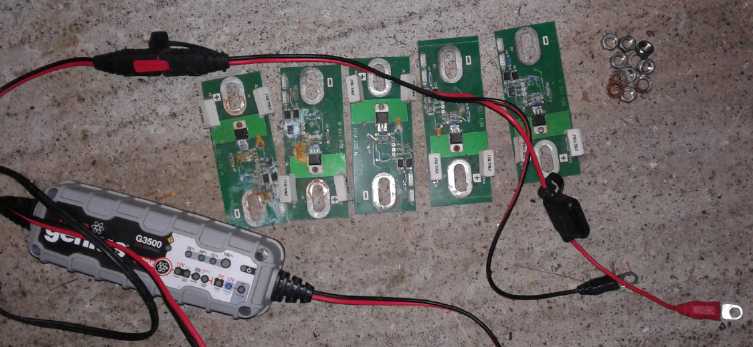 These things were removed when
putting the new
chargers in:
These things were removed when
putting the new
chargers in:
the previous (and inadequate) 2 amp charger and the power-eating shunt
boards that prevent each cell
from going over 4.2 volts by drawing enough current and burning enough
power to reduce the voltage.
(Theoretically there should have been 12 of them, one on each cell, but
I didn't have them all installed.)
Replacing this are the two power adapter chargers, and an AC power
meter to tell when the cells are charged.
"Car
alternator" isolation
diodes soldered to copper plates, to prevent the chargers from
discharging
the cells when unplugged. Note: In order to solder to the body of
the
diodes,
the zinc coating has to be filed
off.
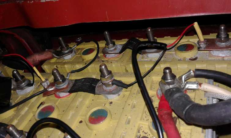 When I went to
connect the first one to the car batteries, it occurred to me there was
a dirty trick they could pull: to draw current from the battery when
they weren't plugged in. Sure enough, it drew about 35 mA. Can't have
the batteries being perpetually discharged whenever they're not being
charged!
When I went to
connect the first one to the car batteries, it occurred to me there was
a dirty trick they could pull: to draw current from the battery when
they weren't plugged in. Sure enough, it drew about 35 mA. Can't have
the batteries being perpetually discharged whenever they're not being
charged!
So each power adapter needs an isolation diode.
Plan For DC Solar Charging (36 Volts,
72 Volts)
With 'only' 6 regulators needed for 36 volts, I came up
with "a cunning plan" for charging from DC using non-isolated DC to DC
converters. By 'cunning' I mean unorthodox, perhaps risky. The charge
controller itself replaces the top DC to DC converter/regulator, so it
only needs 5 instead of 6.
(I was going to show the circuit diagram here, but I think
I'll only show the successful one.)
On some consideration, the lithium cells I've used are
fully charged at about 3.33 volts. 7.0 volts for two is 3.5. Often 3.6
is recommended. However, If I'm using them for solar, they'll get
trickle charged all day. For continuous daily charge, it would be
better that they get to 80-90% fairly quickly and not be pushed hard up
to 100% and beyond. I decided 3.35 volts would probably be sufficient -
so 6.70 volts, carefully adjusted, and to be raised a bit if
measurements showed some cells weren't getting a full charge. So the
voltage from the charge controller would be 3.35*12= 40.2 volts. If the
cells are all charged, there should be virtually no current flowing. If
they aren't charged, they can draw pretty heavily with the charge
voltage just a small bit higher than the cell voltage.
Such a low charge voltage says also that it should be safe
to charge with three cells per voltage regulator, at 10.05 volts. Even
if two cells didn't want to rise above 3.28 volts, that's 6.56 volts
leaving only 3.49 on the other cell. That's well within 'safe' range.
Now we're down to just 3 converters plus the regulated charge
controller for the top 10.05 volts, to manage 36 volts!
(Here's when I realized one could charge 3 in series...)
In fact, now that I think about it, even at 10.5 volts over three
cells, and even with two cells 'stuck' at 3.28 volts, the third cell
will be just under 4 volts. Gosh, the 12 power adapters I ordered could
safely do grid charging for both the 36 volt car and the 72 volt truck,
4 and 8 of them!
(24th) I decided to hook up 12 of my 14 - 40 amp-hour lithium cells in
place of the now pathetic NiMH ones in the solar power system. That's
only about 1500 watt-hours, but if they still have full capacity or
near to it, they should be a lot better. On dull days with 1 KW of
solar producing only 40-60 watts, it was getting tedious trying to get
the 36 volt kitchen sink water heater up to temperature without running
the NiMH batteries down too far, even turning the water heater from 250
to 160 watts. (I didn't actually connect them to the house, but I did
make and test the charger circuit - or rather, 3 or 4 versions of the
charger circuit until I had one that worked.)
I had 5 higher power DC to DC converters with adjustable
current limits. 3 of those plus the PowMr itself could divide the 40.2
volts into the required 10.05 volt segments, charging 3 cells each,
without any further need for any "BMS" ("battery management system").
My one reservation was that the stupid PowMr can easily
decide that a system over 40 volts is a 48 volt system instead of 36
(it's happened to me!), and set the top three batteries on "incinerate"
and "explode". How I wish this most vital of all system parameters was
a manual setting instead of "auto detect"! I decided to set it to 42
volts instead of 40.2, and use four of the DC to DC units for the four
sections. That would only give an input to the top one of 1.8 volts
above the output. but it should be enough. And if the PowMr went crazy
and upped the ante to 56 volts, the top unit would still output 10.05
to the top three cells, even tho its input voltage would be 25.85 volts
instead of 11.85. That would at least theoretically be safe. (OTOH it's
way over the voltage limit for the bottom charger. Maybe I should put
in a fuse in case it blows.)
I had also purchased 5 DC to DC down converters with LED
voltage displays. That would be nice, but they didn't have current
adjustable current limits nor good heatsinks. (Later I ordered some 20
amp DC to DC converters - even without a display, those would be the
best.)
In looking into the current limiting I feared it might be
done with a small sense resistor in the ground line. That would mean
one can't actually tie "Vin-" to "Vout-" and ground them both. But in
stacking them in "totem pole" arrangement to charge batteries in
series, there is no way to avoid tying them together.
So I looked up the datasheet for the XL4016 DC to DC
converter chip that they all seem to use. "Vin-" and "Vout-" are
connected together in all the "typical application" circuits shown. But
the higher power, adjustable current limiting ones I had had something
labelled "R010" connected to Vout-. And if I passed a current through
from Vin- to Vout-, there was a small voltage, 10s of millivolts,
between them.
I decided just to go ahead anyway. The bottom one,
connected to "Vout-" of the charge controller, could be set to a
specific current. The others should follow suit. Right? Right? Like I
said this is an unorthodox plan, intending to eliminate more complex
and specialty lithium "BMS" systems. There are a number of interacting
variable and I think the way to see if it works is just to try it.
I got everything ready, but I didn't actually connect the
wires, because when I put one on, an LED lit up. I decided to make the
final connections with everything in place and ready to connect to the
solar power.
(26th) I took the first battery out to the garage and discovered that
the black wire was on "+" instead of "-". This 12 volt set of four was
connected mirror image to the others. I un-wired everything and turned
it around. As I did that, I suddenly realized there was a flaw in the
whole plan: it was fine when it was charging, but when there was no
solar power, the top set wouldn't be charged. But the other three were
connected to the batteries, and they would use the upper cells to keep
charging the lower ones!
Then I thought of tying all the "Vin+"es together and
direct to the charge controller. As switching DC to DC buck converters,
they didn't care much what the input voltage was. If it was 42 volts
and each one was 10.05 volts, then the top one would be supplied by
42-30.15=11.85 volts, the next one down would be 42-20.10=22.9 volts,
the third would be 42-10.05=31.95 volts, and the bottom one would have
the full 42 volts.
That raised a different problem: the "absolute maximum"
voltage rating on the XL4016 chip is 40.0 volts. But I didn't see much
way around it: the bottom converter would have to be run at a little
over its maximum rated voltage. I really should write the manufacturer
(of the chip itself) and explain why their maximum rating is just a
little low for proper implementation of 36 volt systems. If they could
modify the design slightly (or even just guarantee it) for up to 45
volts, it would be a whole lot better.
But this brought a different problem. Again if the charge
was ON everything was fine. But if it was OFF, disconnecting the power,
the voltage would go down to zero and the voltage on the "Vin+" of at
least the top 2 units (whose "ground" was at 20.1 and 30.15 volts
respectively) would be negative. At least the top unit seemed to short
its output and short circuit its three cells.
I considered a number of options with steering diodes,
none of which seemed to quite work. A diode to each converter sounds
perfect, but the PowMr charge controller gets its own power from the
batteries. The diodes would keep it from powering up. Any attempt to
bypass the diodes would bring back the original problem.
Well, it did say it was a risky plan. I'd much rather have
four isolated output converters - like the AC to DC power adapters.
Come to think of it, even that has a conceptual
difficulty: with the power adapters, either the chargers are plugged in
and the AC power is on, or not. If it's not, obviously they don't
charge. With the solar power, the DC solar output voltage is there
whether or not there's any power from the solar panels, but they'll
still be trying to charge as long as the voltage is there. Batteries
can't charge themselves. That's the problem: that the PowMr gets its
power from the battery as well as charging it. When there's no solar
it's impossible to have power to the controller supplied via its
output, and yet somehow have no power from the controller output. What
is needed then is a solar charging output that is ON only when there is
charging power.
The MPT-7210A charge controller gets its power from the
solar panels instead of from the battery. So it should work. Then the
isolation diodes strategy would work.
Too bad the solar panel voltage is a little too low to
charge the top cells. And that if it was much higher, it would blow the
DC to DC on the bottom cells. Otherwise one could simply use the DC to
DC converters as charge controllers. Hmm... hmm... How about, 3 buck
converters for the lower 3 banks, and one boost converter for the top 3
cells? Straight from the solar panels 32-42 volts. (Via a circuit
breaker, and all diode isolated, of course. Fuses on the outputs?) Of
course, those wouldn't have anything that finds the maximum power point
on the panels and adjusts its current draw accordingly. So it is best
to have a real solar charge controller.
I decided I would have to use an MPT-7210A, then I set
about wiring things up, with diodes to isolate Vout+ from the battery.
There was still another surprise. Even with only Vin- connected, when
Vout+ of converter 2 was connected to Vin+ of the lowest converter,
that one's LED came on. Apparently even if nothing else is connected,
Vout+ will clamp to Vin- by internal diode action, which means it will
still provide power to the unit below. So all units still had to be
powered direct from the main charge controller, which again must have
no voltage if it isn't providing charging current.
But since Vout+ clamped if taken negative to Vn-, it was a
sure bet the Vin+ would as well. So all but the lowest converter would
have to be powered through a diode. I got out 3 more car alternator
diodes - the last ones I had - and wired up the new power line with 4
branches.
Finally, this configuration worked! For testing I didn't
get out an MPT7210A; I only connected it temporarily to the PowMr while
the sun was shining. I had to get the PowMr output up to just about 42
volts to get the top segment to charge. It would seem that if there is
insufficient power available, the bottom banks will charge first and
the top one only once the voltage is sufficient because the lower ones
have charged. Not the most desirable effect, but as long as they can be
charged up fully when the sun shines and they are charged, it should
work.
4 adjustable DC to DC converters
as charge
controllers for each 9 volt segment.
Note the "car alternator" isolation diodes (a) on each orange wire at
the cell connection,
and (b) on each red power wire connection except the lowest voltage
one, at the power adapter.
(& note how I'm standing on the other side of myself to keep my
feet out of the way.)
Here is the final circuit diagram:
I still think four isolated output DC to DC converter units would
be
best... where are they? I thought China made everything.
http://www.TurquoiseEnergy.com
Haida Gwaii, BC Canada