Turquoise Energy News #138
covering
November
2019 (Posted December 2nd 2019)
Lawnhill BC Canada - by Craig Carmichael
www.TurquoiseEnergy.com
= www.ElectricCaik.com
= www.ElectricHubcap.com
Month In "Brief"
(Project Summaries etc.)
- 12/36 Volt DC Infrastructure - WIFI/5G Countermeasures - Ground
Effect Vehicle - 100% Efficient Infinitely Variable Torque Converter -
Woodstove Stirling Steam Engine Generator - New Chemie Batteries
In
Passing
(Miscellaneous topics, editorial comments & opinionated rants)
- Gardening - Winter Cabbage, Sugar Beets - Hearing Improvement Further
Notes - 5G Countermeasures: Biologically Harmful - Small Thots - ESD
- Detailed
Project Reports
-
Electric
Transport - Electric Hubcap Motor Systems
* Ground Effect Vehicle (Still Prototype R/C Model... continued)
* EV Transmissions: 100% efficient infinitely variable torque
converter.
Other "Green"
Electric Equipment Projects
* Working with the Handheld Bandsaw Mill (& Alaska Mill)
Electricity Generation
* 5 Blade Windplant - Windplant Ducts
- Clarkson University Experiments with Windplant Ducts
* My Solar Power System: - Monthly
Solar Production log et cetera - Notes.
* Woodstove Alternator with Stirling Steam Engine?
Electricity Storage
* Turquoise
Battery
Project
(Mn-Zn or Ni-Zn in Mixed Alkaline Salt electrolyte)
November seemed to pass in
something of a blur with day after day going by seemingly with little
to no accomplishment. But somehow I had a lot of writing to do. And it
wasn't a whole loss. I inched forward on various projects.
 I started
making the DC/Solar charging system for the Sprint car, but making a
HAT plug for the charge controller (to plug it into a solar panel(s))
took so long I diverted into looking for ways to make them easy to
produce and didn't get it finished.
I started
making the DC/Solar charging system for the Sprint car, but making a
HAT plug for the charge controller (to plug it into a solar panel(s))
took so long I diverted into looking for ways to make them easy to
produce and didn't get it finished.
Between me and Mike in QC we worked out to make the plug
blades simply straight pieces of flat copper, and to put a ring around
the inner end made of small copper tube. The ring then crimped a piece
of wire to the pins.
Somehow I had never conceived that the pipe, even 1/4
inch, could be small enough. And it doesn't make a 'clean' crimp - it
squashes out. But I got on line and found some still smaller, 6mm and
5mm (and under). One of those will probably be just about right.
The next week we tackled the sockets, studying some 120VAC
electrical socket innards, and Mike came up with a simple "Z" fold,
with the same copper pipe crimp at the wire end. I never think of
things that would waste an extra milligram of metal myself, but these
will be practical -
easy to make and easy enough to use. At least they won't need
soldering. And they will probably be model "A". Later will be some
(bulkier ones) with screw connections - easiest to wire.
Instead of copper, the AC sockets seemed to use brass. We
figured that must be springier, and they need to grip the plug blades.
I had nickel silver, which is still stronger than brass. I would
however note that pure copper is by far the better conductor. Brass is
likely to be better than nickel silver too - sigh, another thing I
should check out before deciding what material to use in production!
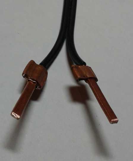
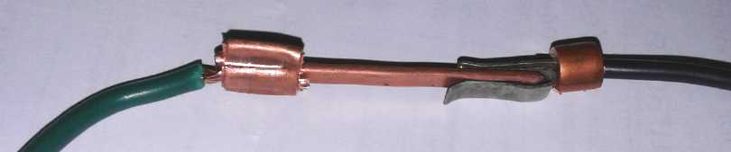 Copper plug blade (ring crimped)
and "Z-fold"
nickel-brass socket
receptacle (ring uncrimped).
Copper plug blade (ring crimped)
and "Z-fold"
nickel-brass socket
receptacle (ring uncrimped).
They seemed to grip each other quite well.
The next task will be to design shells to hold these pins
and sockets.
 And, my fiber optic internet
having come at last, I realized it had both regular 2.4 GHz WIFI and 5
GHz - the notorious "5G". Furthermore it was only a few feet from where
I sit.
And, my fiber optic internet
having come at last, I realized it had both regular 2.4 GHz WIFI and 5
GHz - the notorious "5G". Furthermore it was only a few feet from where
I sit.
Nobody mentioned the "5G" when they were putting it in. I
only noticed the light later. I should have had it mounted somewhere
far from where I usually am.
We are all guinea pigs in the 5G experiment. It's a very
penetrating wavelength (~6 mm) transmitted with considerable power, and
it has never had the slightest testing to ensure that it's safe
long-term. There are already troubling signs that regular WIFI can in
fact cause people serious problems.
No one should imagine that transmitted microwave radiation
somehow goes around their body. Suing someone for criminal negligence
later won't help anyone who has developed cancer or who has had a
defective baby(s) in the coming years. I expect eventually "5G" will be
scaled back in power of even abandoned as being too unhealthy.
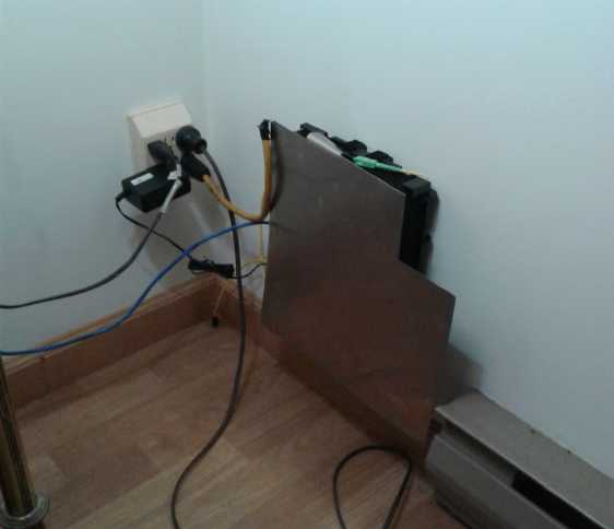
Even in front of this grounded piece of metal, the cell
phone still shows four bars WIFI from it. How strong are the signals
without the protection?
Ground Effect Vehicle - to open up the BC north coast
and other rugged, isolated and island territories
I modified the canard to hold the ducted fans and then
mounted them. I put in a heavier (1/4" dowel) pivot since all the
thrust will go through it. I redid the rear of the wing (ex "elevator")
after melting the covering with the heat gun, and screwed it onto the
back of the wing. I mounted the servo to move the canard up and down,
and by the end of the month I tested it.
It was starting to look like it might be finished some day.
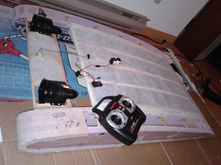 It works!
Moving the "elevator" control on the handheld transmitter
moves the canard up and down. With the ducted fans mounted
on it, aiming it up for take-off blows the air under the wing
for more lift, a highly desirable ground effect craft feature
"incidentally" incorporated by putting them on the canard.
100% Efficient Infinitely Variable Torque Converter - for
improved efficiency of road and rail transportation
After all these years muddling around, and finally having
a very clear concept of how everything should go together last summer,
and then having found a piece of pipe just right for a spinnable
housing for the planetary gear, I couldn't help but start working on
it. This month I got and mounted on the shafts two strong double row
sealed
ball bearing units that seemed the ideal type for this application.
(ordered in October)
I found some aluminum disks that were usable. But I was
unable to readily turn them as desired. I'll need to go to some
contortions to mount them on so they fit "in the gap" of my "too small"
lathe.
Instead I focused on making a coupler to couple the motor
to the planetary gear. Somehow turning a little piece of pipe to exact
size was an all day job, and I still need to weld it to the end of the
splined shaft stub that fits the planets gear.
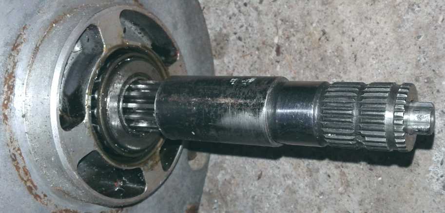 Shaft coupler pipe.
It'll be "pound it onto the motor shaft and put in set screws",
and "weld the pipe onto the splined shaft stub".
I got it to pound onto the shaft aligned, so hopefully
I can weld it on still solidly held straight.
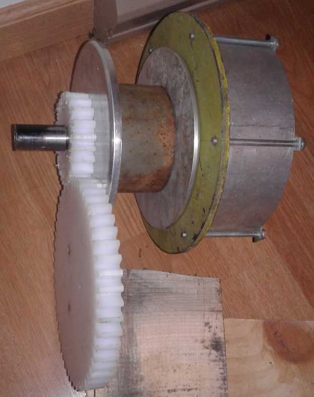
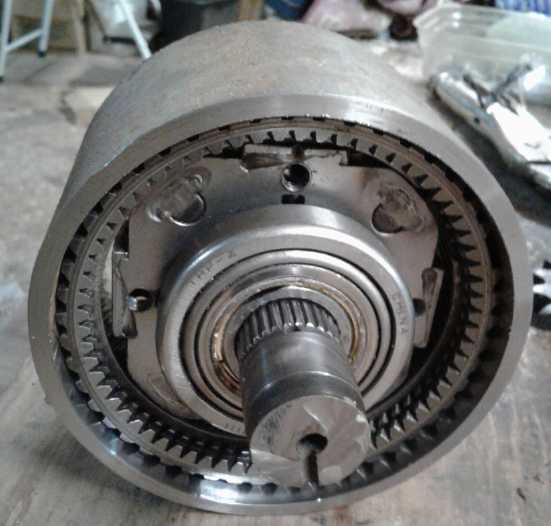
Now having all these pieces I could start trying to put things
together. From the left (below):
* The shaft to connect the motor (Motor mounting off to left to be
created).
* A gear to connect the assembly to the car's differential (which will
hold the large gear).
* Aluminum end plate.
* Planetary gear housing (to be oil filled - the end plates seal the
gear housing.)
* The other end plate.
* The big centrifugal clutch drum.
All the parts seen here are tied together and turn
together as the car moves except the motor shaft, which is connected to
the planets assembly inside the planetary gear. Since they are, both
end rings and the plate of the clutch drum will all be bolted through
from left to right with long bolts, ensuring everything is held solid
and squeezing the oil seals tight.
Sizes and spacings conspired to insist that the drive gear
had to go on the left end without touching the motor shaft. (There's
more to do to mount it to the end plate. I may use sprockets and a
chain instead of my perhaps dubious gears.)
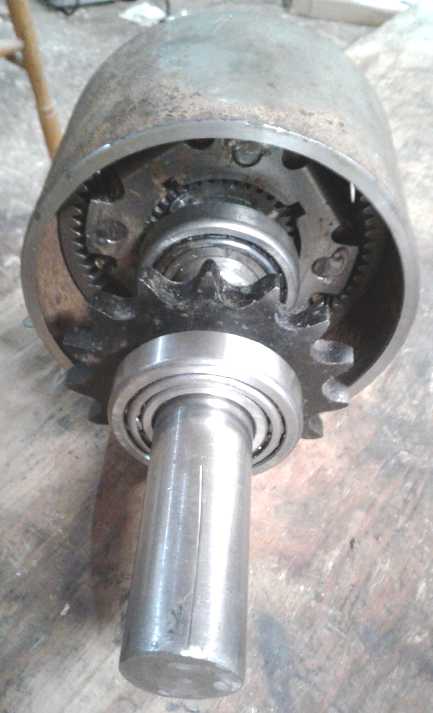
Seen in the second image from the other end (below):
* The centrifugal clutch inside part (with UHMW centrifugal shoes to
contact the aluminum drum.)
* An end bearing to hold it all in line. (Mounting to be created.)
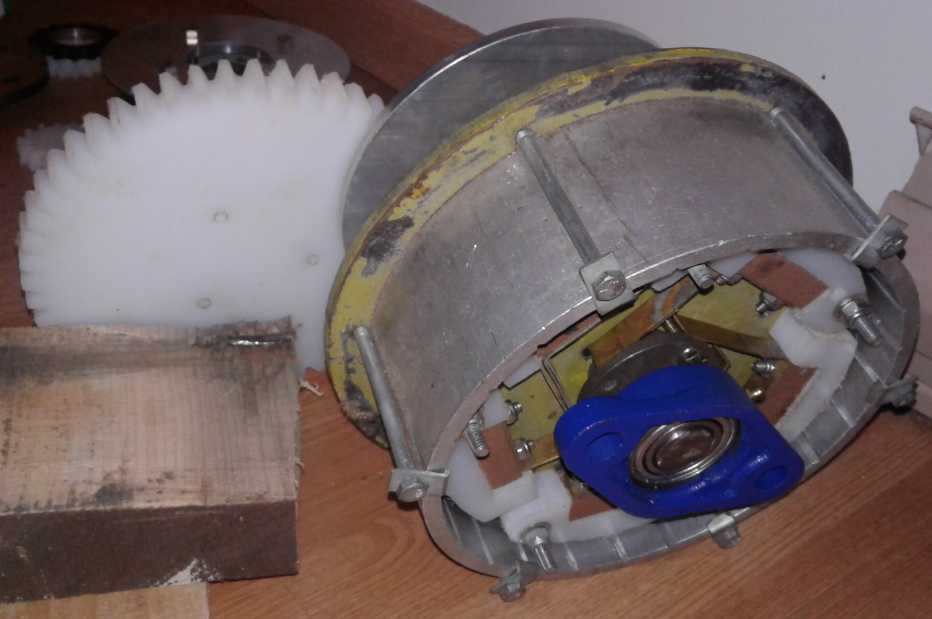
Some may ask how any mechanical mechanism could be 100%
efficient. To review the operation, the ring gear/outer drum of the
planetary gear is attached to the car's differential by gears or a
drive chain. The motor turns the planets assembly. Since the car isn't
moving, the ring is stationary and the sun gear spins. The sun gear's
shaft connects to the inside element of the centrifugal clutch, which
is thus turned at three times the speed of the motor.
As the shoes fly out and engage the drum, it turns it and
the car starts to move.
As the car starts moving, there actually are losses. Even
a
planetary gear is only around 97% efficient, bearings turning have
small losses and the centrifugal clutch is an unknown. But as it all
gets
up to speed and less torque is needed, the clutch shoes lock to the
drum and then everything spins at once: motor, centrifugal disk/shoes
and the drum, and both sides of the bearings are turning together.
There is no relative motion, so nothing to cause losses. (The end
bearing turns, but some shaft bearing would doubtless be needed anyway.
And I suppose one might count air friction...)
Woodstove Stirling Steam Engine Generator - Reliable winter
electrical generation at home
Stirling
Engine
Animation
from
Wikipedia
 Owing to lack of sunlight to make electricity, and with a woodstove TEG
(thermo electric generator) seeming to be not much bang for the buck,
and with steam engines needing too high of a temperature, I thought of
Stirling engines. I didn't understand how they worked, but I knew that
like TEGs, they ran off the difference in temperature between a hot and
a cold side.
Owing to lack of sunlight to make electricity, and with a woodstove TEG
(thermo electric generator) seeming to be not much bang for the buck,
and with steam engines needing too high of a temperature, I thought of
Stirling engines. I didn't understand how they worked, but I knew that
like TEGs, they ran off the difference in temperature between a hot and
a cold side.
So I studied them. Youtube has many working examples.
They're pretty simple, but they aren't very powerful for their size.
I'm sure they can be improved.
It seemed to me, first, that the stroke of the displacer
is wasteful. It creates the most heating and cooling effect, the most
propulsion, when it's at either end of the cylinder. Instead it spends
too much time in the middle and never actually quite gets to the ends.
That could certainly be improved by having it sit right on either end
for almost 1/2 the stroke.
Second, woodstove tops often operate just in the region
where water boils - a low simmer. If a large diameter cylinder had
water in the bottom, and if there was a phase change from water to
steam in the heat part of the cycle, and back from steam to water in
the cooling part, the volume of gas in the cylinder would change far
more than just with heating and cooling air, giving the stroke much
more power for the size.
By turning an efficient alternator, perhaps as part of the
required flywheel assembly, I thought a good goal would be making 100
watts of electricity - day and night for as long as the stove had a
moderate fire going.
Just what I need, another project!
New Chemie Batteries - Better,
cheaper
mass
electricity storage
I didn't do an awful lot on these this month. What I did
do led me to I re-think a few things.
At the start of the month I had another zinc tab corrode
off from the rest of the electrode. I decided I should order some zinc
that was at least said to be pure - there were no claims to
purity on the "rooftop moss killer", and there was all always that
black crud left over when I used up a sacrificial electrode for
electroplating. How could it be pure? Would pure zinc work better?
Probably!
The experimental copper electrode with calcium oxide on it
had also corroded away, but apparently radiating from one point on the
tab. So I was left wondering whether that was just where it (probably)
got scraped at that point when putting it into the cell, or not, and so
whether the idea worked or not. But then I also thought that gold
plating the copper might be a better plan. It wouldn't have to be very
thick - hardly enough to see - and it would probably protect the copper
nicely. (especially at manganese dioxide voltage, which is below the
gold-to-gold-oxide voltage.) My old gold brush plating solution (from
2004) didn't seem to be working any more, so I ordered a bottle of
"proper" gold tank electroplating solution. (Almost 200 dollars - Ouch!)
If no metal works there's still graphite. Metal would give
higher current capacity.
Finally I also decided it would probably be practical to
make the cells to lie down flat instead of standing up. That'll need a
new (3D printer) case design. It will also allow very large but thin
individual cells that won't keep falling over.
In Passing
(Miscellaneous topics, editorial comments & opinionated rants)
Gardening - Winter Cabbage, Sugar Beets
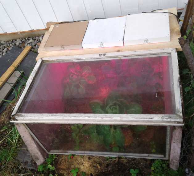 In the spring I had planted cabbage in the garden. By fall, just like
last
year, it hadn't formed heads. Somebody said cabbage had to go in the
greenhouse. Certainly the ones in there seemed to grow better. On
November
8th I decided to try taking a greenhouse to
the cabbage. I put some walls of scrap styrene foam and glass
around them, another scrap window on top plus three 12"x12", 45 watt
LED grow lights. I covered over the top of the lights with a piece of
plastic. It was pretty slipshod (removed for picture), but we'll see
how they do - if it
doesn't get too cold.
In the spring I had planted cabbage in the garden. By fall, just like
last
year, it hadn't formed heads. Somebody said cabbage had to go in the
greenhouse. Certainly the ones in there seemed to grow better. On
November
8th I decided to try taking a greenhouse to
the cabbage. I put some walls of scrap styrene foam and glass
around them, another scrap window on top plus three 12"x12", 45 watt
LED grow lights. I covered over the top of the lights with a piece of
plastic. It was pretty slipshod (removed for picture), but we'll see
how they do - if it
doesn't get too cold.
Toward the end of the month it was almost surely too cold. I started
leaving the lights on full time to keep them from freezing. I'm not
sure I see any growth. Perhaps
if I had done it a month earlier? or two? I'll persevere for a couple
more weeks, but it doesn't look promising.
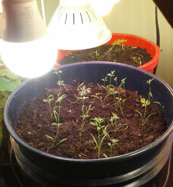 I decided to try growing carrots indoors. I hooked up the "LED indoor
garden" in the corner of the kitchen. But only lettuce seems to be
doing very well so far. I think the corner if not the whole kitchen is
just not warm enough. I think I'll insulate around the lights and maybe
even turn on the electric heat just so it heats that space. (Maybe
replace one LED with a 100 watt incandescent bulb in one socket, with
the small fan near it, just
for the heat?)
I decided to try growing carrots indoors. I hooked up the "LED indoor
garden" in the corner of the kitchen. But only lettuce seems to be
doing very well so far. I think the corner if not the whole kitchen is
just not warm enough. I think I'll insulate around the lights and maybe
even turn on the electric heat just so it heats that space. (Maybe
replace one LED with a 100 watt incandescent bulb in one socket, with
the small fan near it, just
for the heat?)
We've heard about the
staggering global crop losses in
corn, wheat, soy and even potatoes (almost nothing easier to grow at
home than potatoes!), and the staggering devastation of vast herds of
porkers and beefers. Now here's another whammy: as fall turns to winter
the summer's stats from sugar beet farming have come in and the crops
are way down: grand disaster in southern Alberta and south of the
border too. People trying to source sugar simply can't get it. Rogers
has apparently declared "Force Majeur" on contracts and put its usual
customers on allocation: there just isn't enough to go around. So
places report sugar cane crop failures, but Louisiana had a bumepr crop.
And NASA's predictions for the next solar cycle indicate
we're in for a grand solar minimum like the Dalton minimum: 30 years of
cold, rainy weather - worse next year than 2019. The conditions for
that grand depopulation of the
planet by mid
century are really starting to take form!
So I looked up sugar beets. I've never seen them in stores
in the spring, but there are some seed suppliers who have them
available. I should look further to see if growing them here sounds the
least bit feasible. (back to youtube!)
Later I heard that the phenomenon is being called
"farmageddon" in the USA. Farms are going bankrupt en masse (in Europe,
too), there's an unprecedented wave of farmer suicides, and food
companies are going bankrupt when they can't get inputs at prices they
can pass on - especially dairies because the price for milk is "fixed"
by the government. ("Fixed"? Don't they mean "Broken"? How about
"Rigged"?)
http://www.iceagefarmer.com/2019/11/07/food-system-collapsing-actively-rapidly-urgent-warning/
https://electroverse.net/in-the-last-30-days-the-u-s-set-7112-new-all-time-low-temperature-records-vs-just-the-1605-max/
And in the face of this, a NASA temperature map shows
globally slightly warmer average temperatures for 2019 as a whole most
everywhere except a big, dark "cold hole" over most of North America.
Not that farming has done well anywhere. The staggering losses
everywhere have
different causes in different places.
Hearing Improvement Further Notes
In TE News #136 I wrote of improving hearing by dripping vegetable oil
in one's ears. It's also supposed to help reduce or eliminate tinnitus.
I found this idea from more than one source. But how could it help?
This month I read an article saying we lose hearing
because of our noisy environment. It mentioned things like hair blow
dryers, shavers, food processors, blenders and coffee grinders, many of
which are pretty loud for short periods. In #136 I also mentioned
noises that persist over long periods like refrigerators, fans and
heating and air conditioning systems, traffic, and music or continuous
babble - radios, TVs and so on. Since the noise is ubiquitous we pretty
much stop noticing it, but I suspect that both types of noise have long
term deleterious effect.
The article went on to say that with indigenous people who
don't have all these electrical noises around them all the time, old
people hear as well as young people. This tends to validate the idea
that QUIET is what one needs to retain hearing, or to recover it if
[that's an IF in a mechanized society?] if it has been lost. And that
the way the oil works is as a high-frequency selective "earplug" that
works for hours, reducing the levels of noise entering the inner ear
mechanism, perhaps by 10 dB.
This is obviously a very slow acting, long term treatment
- a reversal of the slow, long term loss of hearing. And obviously of
course it must be done along with all other sensible hearing protection
precautions one may take. And eliminating environmental noise as much
as possible.
5G
Countermeasures:
Biologically Harmful
(Oops, I've written this up twice)
My fiber optic internet
finally came in late October. I had the fiber cable end and the
interface box put in near my computer desk. It's great to have good
internet again! It came with WIFI.
When I finally
bothered to look at it, I was shocked to see that it also came with the
controversial 5 GHz as well as 2.4 GHz WIFI. (now I finally know
why they call it "5G".) This is getting up into a biologically
destructive range and I'm sorry it's there. Even 2.4 GHz WIFI can be a
damaging level of radiation if, for example, you hold a cellphone to
your ear for hours per day, or there is a cell phone/WIFI station too
close where you are routinely present... or sit too close to the WIFI
box in your house for too many hours a day. (I have heard stories -
rumours - that brain cancers have been observed from the first, and
other fatal cancers from the second.) Does anybody imagine that these
rays somehow go around people instead of through them? I hardly care if
I have WIFI at all. Why would I want to subject myself to even more
penetrating radiation? I wish I could just turn it all off. I wish I
had had it installed in some far corner of the garage I rarely go into.
I'd have run any length of ethernet cable in preference!
"5G" is a very considerable radiation and there have never
been tests done on it to assure that it's safe. It is down to 6
millimeters wavelength, even shorter than "microwaves" (centimetric
waves) and headed toward the infra-red band. In fact we are guinea pigs
in a vast experiment. I put a piece of sheet metal (cupro-nickel, but
steel would work too) in front of it and connected it to a ground with
a 3-prong electrical plug, only using the ground pin. That way the
radiation can't come directly toward my computer desk where I sit a
lot. Even so my cell phone shows four bars if I turn on its WIFI. (I
had been cutting pieces from this sheet. It had a convenient "tab" that
I simply bent over to hang it from the unit itself.)
It won't help you to say, when you have terminal cancer,
"Nobody told me it wasn't safe!" Anyway "they" will deny that the 5G by
your desk could have had anything to do with it and you won't be
absolutely 100% certain yourself. But then, "they" told you that
smoking was safe, that thalidomide was safe, that glyphosate ("round
up") weed killer was safe, that GMO wheat was safe (that's when
widespread "gluten intolerance" started), ...
Small
Thots
* I noticed a title from "Provident Preppers" on youtube, who grow
their own gardens. I didn't watch it, but it said something about that
they had lived for 90 days on their stored food and garden produce,
without going to the grocery. Of all the crazy ideas, testing to find
out how you actually make out and finding any deficiencies in your
preparations!
* CDC Director Robert Redfield said people should stop referring to "a
coming time" when antibiotics won't work: "It's already here." Many
microscopic threats are "urgent", "serious" or "concerning".
Along with suddenly developing food scarcity, we are
setting up for the global pandemic or pandemics which will end the
unsustainable "population bubble" humanity is now in. The African Swine
Fever epidemic is a foretaste of how an entire species population can
drop dramatically and rapidly. (I'd say globally but it hasn't hit the
Americas yet. We are desperately trying to keep it out. But if some
European pork tour group books a flight to vacation to
Disneyworld, look out!)
* Freedom of Speech is not about being agreeable. Freedom of speech is
about freedom of thought. It is about being willing to hear things and
ideas that you don't want to hear. It is about letting people express
themselves even if you don't agree with them - and even if you think no
one agrees with them. Even if you think they are wrong and what they're
saying is idiotic. It's about allowing things to be said that you
fervently hope others don't believe or agree with. If what someone says
really is wrong, they will gain few adherents. If it is right, you've
avoided putting yourself in the wrong by arguing against it or worse,
preventing people from hearing it.
When freedom of speech is infringed by authority, it is a
case of "might versus right". If we don't believe might makes right, we
should want no part in suppression of free speech. Whether you like or
dislike Alex Jones and what he says, when he was almost simultaneously
banned from Youtube, Facebook, Twitter et al, it was a sad day and a
sad precedent for free speech for all. "First they came for the
Jews..." ... First they came for Alex Jones, then a whole pile of other
people you won't find videos or articles from any more (even their old
ones), and they're subtly going after the whole of alternative media -
keeping them out of all but the most direct search results,
demonetizing
their videos until everybody interested has already watched them, and
so on.
Many think that the alternative media is "just a bunch of
nuts" anyway. But some of the better channels provide a link to a page
with the mostly credible sources of their information - which you
virtually never get from the "mainstream media". From them its "experts
say", "scientists say" (unspecified experts), stock or other footage
pawned off as being news, even outright lies, with no provision for
checking for yourself. And on Youtube and Zerohedge (at least) comments
may be entered below the video, so if others have more information or
disagree with the content, you can find out quickly by reading a few of
them. And you can enter your own comment.
Those who are in corporate and government and "mainstream
media" power are afraid of truth. They don't want you to hear other
opinions than their "narrative", and they use their bureaucratic power
to stifle
their airing, without being so obvious about it that there is a huge
and immediate backlash that exposes their dictatorial habits.
"The truth never suffers from honest examination." - Jesus
* If humans try to go to Mars without protection against cosmic "rays",
they may arrive blind if at all. Recall that the lunar astronauts
reported seeing flashes of light with their eyes closed once they were
outside of Earth's Van Allen Belts of protective magnetic shielding.
Later some of them got cataracts early in life. That's from being just
a week outside Earth's magnetic protection.
Vegetation might grow outside the protective zone. It
doesn't have delicate eyes or nervous systems. It seems like Ganymedean
vegetation has spread to many spheres (even little "oids") without air,
as long as there is good soil and no special harsh radiation such as
Jupiter and Saturn sweep around with their rotation. (This is why
Callisto and Iapetus are covered with "dark", "fluffy" complex
polycyclic aromatic hydrocarbons organic matter (scientists' findings),
plant life (my interpretation), but on their
leading hemispheres only.)
ESD
(Eccentric Silliness Department)
* We used to have "television sets". Now with flat screens they are too
thin to set anything on top of. It will fall off. Should we still call
them "sets"?
* "Zero" and "seven" are single digit numbers. Why do they, alone, rate
two syllables? Especially "seven" grates on my mind when counting to
ten.
Sometimes used "oh" is easily confused with the letter
"O" - which also looks the same when written**. (or the word "owe", as
in "I 0 1 2 thee 4 fine help.") Maybe we could shorten "zero" to "zo"?
That's pretty unambiguous. Or use the British words, "naught", "aught"
and
"nill"?
We could perhaps shorten "seven" to "sev"? The French word
"sept" with the silent "p" - unlike "sept-ember", the 7th, er, 9th
month] might be good except it is already much used as, in
"television set". Okay maybe better, "sept" but sound the "p"? That has
good precedent in language.
** I've seen a scanned book with a strange word, "loomm". It was
really "100mm". And in the same book I think "ydmrn" was probably
"92mm" (or 93 or 96).
* There's something funny about the flavor of wry bread.
* Lifting 100 grams is easy. Lifting 100 killergrams is hard.
* Earthly vegetation that might grow on Mars: Marzipan, Marsmallows.
* Algorithms: The daily comings and goings of Al Gore.
* Bacon supplies that may be in short supply owing to the "pig
apocalypse": bacon powder, bacon soda.
"in depth reports" for
each project are below. I hope they may be useful to anyone who wants
to get into a similar project, to glean ideas for how something
might be done, as well as things that might have been tried, or just
thought
of and not tried... and even of how not to do something - why
it didn't
work or proved impractical. Sometimes they set out inventive thoughts
almost as they occur - and are the actual organization and elaboration
in writing of those thoughts. They are thus partly a diary and are not
extensively proof-read for literary perfection, consistency and
completeness before
publication. I hope they add to the body of wisdom for other
researchers and developers to help them find more productive paths and
avoid potential pitfalls and dead ends.
Ground
Effect
Vehicle
(first
the
R/C
Model)
Canard & Ducted Fans Mounted on
Canard
Having decided to have a front canard to replace the rear
elevator and never having seen such a thing, I found the "WISES" ground
effect model video. It seemed to
fly quite well with much more positive response when put to climb or
descend.
 The "WISES" ground effect craft -
Full size
model test prototype 2011. (Why does it keep
The "WISES" ground effect craft -
Full size
model test prototype 2011. (Why does it keep
buzzing that poor guy in that boat? ...Yes, the one holding that, um...
radio control... unit?)

 Although it was "full size", 7
meters long, he
built it lightweight and graceful,
Although it was "full size", 7
meters long, he
built it lightweight and graceful,
so it would quite fly slowly. Why? Because he didn't have a high speed
chase
boat. A faster version such as is planned for the manned craft would
have
quickly flown out of control range. (I wonder how mine will fare?)
Then, having decided to move the ducted fans to the
canard, I looked at the "WISES"
ground effect video again. I had been trying to see where the propeller
was but it seemed invisible. I had thought it must be at the front of
that long thin nose. Finally I noticed there was (sure enough) one on
each side on
the canard, faintly visible in some of the footage. Essentially the
same place as my own new plan!
So while both my reconfigurations were already made, the
high-performing WISES craft provided strong reinforcement that I was
probably making the best choices. At least I was in good company.
And I believe the ducted fans are a better choice than
open propellers: higher static thrust, and higher above the water, so
they can be mounted lower. Around the 12th to 15th I picked away at the
canard,
ripping off some of the cloth, adding two ribs for mounting the fans,
and filing the front and back edge spars to more streamlined inside
shapes. Of course the canard was made without the fans in mind, but
even so it needed to have the lengthwise strength that the famous Haida
Gwaii aircraft spruce provided.
I changed the dowels from 1/8 to 1/4 inch as they would
now be taking all the propulsion thrust force along with lift. I
couldn't have the canard with the motors break off and fall into the
water!
And of course, the "ESC" motor controllers had to go in
near the bows beside the canard - the one part of the hulls I had
covered over on top! (Won't need to get in there, oh, no!)
 (23rd) I finally decided to
try heat shrinking the covering, which seemed to be recommended by all
the modelers for all the coverings they used. I had started to make a
test piece, a short version of the canard, but then I tried on the top
of the rear elevator (now to be a fixed part of the wing, but already
made separate). Instead of shrinking and getting taut, the PP cloth
stretched and sagged. I moved the heat gun in a little closer - not
close - and a
hole appeared and spread too quickly to react. I would have to
sand it off and redo it.
(23rd) I finally decided to
try heat shrinking the covering, which seemed to be recommended by all
the modelers for all the coverings they used. I had started to make a
test piece, a short version of the canard, but then I tried on the top
of the rear elevator (now to be a fixed part of the wing, but already
made separate). Instead of shrinking and getting taut, the PP cloth
stretched and sagged. I moved the heat gun in a little closer - not
close - and a
hole appeared and spread too quickly to react. I would have to
sand it off and redo it.
Okay! No heat for PP cloth/landscaping fabric! Either
it'll shrink a bit and become more taut when the finish is applied, or
it will stay as-is.
I had dabbled in it just
occasionally, and eventually got the ducted fans mounted in/on the
canard. By the 30th I had mounted and was able to attach the
servomechanism to the canard.
It works! As the "elevator"
control is
moved up and
down on the handheld transmitter, the tiny receiver
picks up the position info and the servo twists,
pushing the rod, and the canard aims down and up.
With the canard pointed up, the air from the fans is blown
down under the wing. With the sides and back largely "boxed in", this
somewhat "inflates" underneath like a hovercraft, allowing takeoff at
lower speeds. This is an advantage built into the propeller angle of
some of the radio controlled models. But in this design that steep
downward air angle is obtained as part of the vertical control, and
only when it's useful.
There is one part I haven't gotten to yet:
turning and maneuvering. There is no provision on the motors (or the RC
control) for going in reverse. It would seem the only way is to swap
two of the
three power wires. For the model, at least for the first run, I think I
will just have to say "if it was the real thing you could easily
maneuver up to a wharf or float."
My present plan for turning has been to turn one motor
down and
the other one up. But once again there is no provision for that, which
would have to be a "double" throttle stick in the control transmitter.
I'm thinking I need to make a special circuit board to "reinterpret"
the signals from the motor speed control and the "rudder" control, and
use the "rudder" control to speed one up, and slow the other one down.
The other alternative is to put an actual rudder on the
craft, and power both fans equally. As with inability to edge up to a
wharf, I'm not fussy about the idea, but it may be a good stopgap for
initial testing.
EV
Transmissions:
Off-the-Shelf
Planetary
Gear (for Miles Truck),
100% Efficient Infinitely Variable Torque Converter
(5th)
In spite of it not being high on my priority list and trying to get out
the October newsletter, having a plan for making a planetary gear
enclosure and the parts to do it, I was inspired to not bother waiting
for the
stock gearbox and start putting together the custom one for the Sprint.
I didn't have a bearing the right size for the
motor/planets side. It was 30.5 mm/1.20". There were lots of 30 mm
bearings, but none 30.5 and none 1.20 inches. I had a couple that were
1.375 inches. I found a brass plumbing piece that was a perfect fit to
hammer into the bearing center, and I cut a short piece off and did so.
Then I cut another piece and cut a diagonal groove across it. I widened
the groove until it fit inside the other piece. So I had the bearing
with two shims inside. It fit perfectly onto the flange on the planets
assembly. The ring gear already had a previously made shaft on it that
took a 1.0635" ID bearing, which I had some of. So now the planetary
had a bearing on each side of the ring gear.
(6th) I cut off a 70 mm piece of the big (~4-1/2") pipe with a zip
disk. Then I put it on the lathe and squared up the cut end. Then I
used a boring bar and did some turning on the inside on one end,
extended into the middle. Then I turned it around and worked on the
other end, but inside only to 10 mm depth.
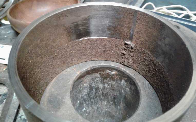 Starting to turn the inside of
the pipe to
"prfectly round" and the right size to hold the ring gear.
Starting to turn the inside of
the pipe to
"prfectly round" and the right size to hold the ring gear.
 With the ring gear pounded in.
 The motor end with the planets
assembly and
stub splined shaft.
The motor end with the planets
assembly and
stub splined shaft.
Soon I realized that the "cup and cone" bearings would have leaked
oil, so I replaced them with "double row sealed ball" bearings.
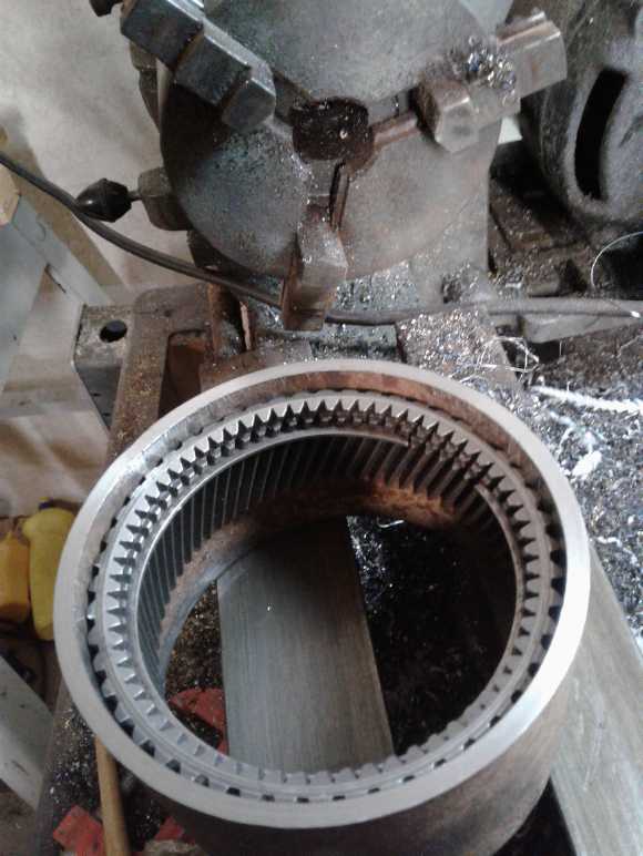
 The centrifugal clutch end. The
long shaft on
the ring gear,
The centrifugal clutch end. The
long shaft on
the ring gear,
which was "ready made" from some previous attempt,
proved to be just long enough.
Then I turned it around again and widened the inside
diameter some more. After going a very tiny bit at a time (seemingly
far too many times), I had a fit where I could pound the ring gear into
the pipe. So it had machined ends and a solid fit. The ring gear could
have gone another 1/8" in (I was just guessing the depth to cut), but
its was wider side to side than the planets, so there was some room
for play and it all fit. The piece of pipe was about 1/4" longer than
it needed to be. (I was guessing that too, but I had left a bit extra
in case my guess was short.) Here again I was in luck because the
1.0635" section on the shaft extended out an extra 1/4", so all it
needed was a spacer. So everything fit first try without having to
pound the ring gear out and bore deeper, and without having to cut the
pipe shorter.
(7th) I noted that it was going to be very hard to get a good oil seal
with cup & cone bearings at each end. Well, not much I could do
about that! I could change to sealed needle bearings, but... but what?
I went out and looked, and while I didn't have just the right sizes, it
looked like they'd actually even be a better fit. They had side walls
and were filled with grease, but I suspected a bath of oil on the
inside would get in and seep through. But at least it would "seep" and
not "gush" through.
So I went online to vxb.com (bearings store in California
with a good online catalog and prices listed). I ended up picking two
"double row, sealed" ball bearings that I hoped would fit - and not
leak, or not much. (One might be too tight, the other loose - best I
could find.) I ended up 100 $C lighter. How much cheaper to make than
to buy, again?
I really still didn't have a complete plan. I took the
assembly out to the car. It looked like the thing to do would be to put
the chain sprocket on the motor/input end and leave the other end just
for the centrifugal clutch. Other than having to make some large
support with a bearing on the end to support the end of the clutch
inner shaft, an extender shaft adapter/coupler for the motor and maybe
cut out a recess in the sidewall for the body pipe of the planetary
assembly, everything looked like it would fit in best - would actually
fit in at all - that way.
It seemed a great pity the the chain sprocket wouldn't fit
around the pipe/planetary gearbox. That would have simplified things
immensely. But such a large sprocket would have made for a very low
reduction ratio to the differential - less than 2 to 1, when it needed
3 or 4 to 1.
At this point the impetus ran out. On the 15th I took it
to the cafe at lunch for ideas (where I was reminded that the end
plates would leak without an O-ring or a gasket). I also found some
aluminum plates I could use for the end plates. But basically it was
now "wait for the bearings to arrive".
The company selling me the 5 to 1 planetary gearbox for
the Miles truck was also dragging their heels. I had to phone to see
what was happening and give a couple of instructions to get them to get
on with it. Then on the 15th they sent a drawing of the gearbox and
asked me to sign it saying it was what I wanted! Oh well, somehow I
didn't seem to be getting a lot done on any projects anyway. On the
21st I finally got another e-mail... saying I should approve their
shipping
method (Fedex)! Do they really want to sell things?
That same day the bearings arrived. As I expected the 30mm
I.D. one wouldn't quite go onto the 30.5mm hub protruding from the
planets assembly. I put the hub on the lathe and filed it down. (I was
surprised I could - weren't these parts "case hardened"? Maybe not the
outer shell for the planets.) As
expected the other one was too loose. I started making a brass spacer.
It was going to need a lot of sanding down. Somehow when I was putting
a sanding disk onto the drill press, I glanced somewhere and saw some
old previously made steel spacer that looked about right. Sure enough
it was a perfect fit. I must have had to fit a 1-1/8" something onto a
1-1/16" shaft before - probably the same shaft in some previous attempt
at a torque converter years ago.
In the meantime I had been down to the dungeon, er, root
cellar, er, storage room, and found four 3/8" thick aluminum disks I
had made trying to do a flat belt to the differential years ago. The
centers were too big for the bearing, but they also had some bolt holes
which could be used to attach new centers. They should make good end
caps for the rotating planetary gearbox.
(22nd) I went to put one of these disks on the lathe, but it was too
big. I asked my neighbor if I could use his larger lathe (he had been
given this beautiful modern lathe and didn't know how to use it), but
the center of the 3-jawed chuck was too big to fit into my center hole,
and the outer jaws were too small to go around the outside. I went home
disappointed.
There were holes in them for SDS hub bolts, and that must
be how I had originally made them on my lathe, but SDS hubs aren't a
perfect thing to center on. Oh well...
How to connect the motor?
Trivial in the design concept, tricky to actually do.
(24th) I left the disks for the moment.
There was a question mark
around how to connect the motor to the planets assembly of the
planetary gear. And that connection would affect the spacing and inside
size of
the drive gear going to the differential, so I wanted to do it before I
got too far on that. The motor had a short shaft. There was a short
shaft stub that fit into the spline of the gear. It seemed to need a
short
hollow shaft to couple them together. On a hunch I went into a drawer
full of scrap
copper wire, pulled out most of the wire, and found a long forgotten 2"
long, 28 mm O.D. steel pipe at the bottom. (I didn't know it was there,
honest!) It looked a bit small in diameter, but I had nothing else
close. It
turned out that if the inside was turned out a little, it would fit
over the motor shaft. I made it so I would have to bang it on, and I
would add a couple of set screws. If that didn't hold, I might have to
drill a hole through the shaft and put a bolt through it - worry about
that if it happens.
The other end was more of a puzzle. If I turned it out to
fit the shaft stub, it would be so thin it would probably split open.
There was a bit of the end of the stub shaft that was narrower, about
23 mm. I could probably turn the pipe to accept that, but it was only
about 3/16" long - not much to grip. I might turn down the outside end
of the stub shaft, but it might be a bad idea too. (Aren't those things
"case hardened"?) Lacking other
inspiration, I turned out the inside of the pipe to take the 3/16"
long narrow end of the shaft. Again I made it a "pound in" fit, but
still it
wasn't much length to grip onto.
Then I thought that with the two pieces tightly held in
perfect alignment, I could weld them together. The idea of welding
something to the shaft stub had occurred to me before, but I was sure
the two parts wouldn't be in good alignment no matter how careful I
was. This would be perfect because it would be solidly held in
alignment during the welding.
I fitted everything together. Somehow the images with
extensive descriptions are above in "November in Brief" and I won't
repeat them here.
Other
"Green"
Electric Equipment Projects
Handheld Bandsaw
Mill (& Alaska Mill)
(7th) Along with ordering some other bearings I ordered a couple of
needle thrust bearings that I thought would be more suitable for the
saw than the ones I just got.
Level?
(10th) I conceive that for milling narrow or misshapen boards or when
using a narrow or imperfect guideboard, it may be useful to put a level
on the mill. One can then maintain the level from one end to the other
as one goes and avoid cutting twisted boards.
I thought of this as I was cutting on top of slightly
convex "cupped" previous cuts without bothering to fasten down the
guide board. It was too easy to tilt the mill side to side, and it is
often the case one can make small adjustments by pushing down harder on
one side of the mill then the other. Just a few boards after thinking
of this, the guide board actually started tipping off one edge without
me noticing, and my cut was more and more diagonal. With a level I should
have noticed something was wrong sooner, before it was way off. Over
much of the board the two faces were nothing like parallel. (I screwed
the guide board down and put in chunks of bark to stabilize the net cut
to get back to something like level, and that next board of course also
was a wedge
shape.) Anyway I got twelve 2" by 4"s from about a 24" tall cant. (The
top and bottom ones, being sapwood, have a lot of worm holes.)
Ow! A Nail!
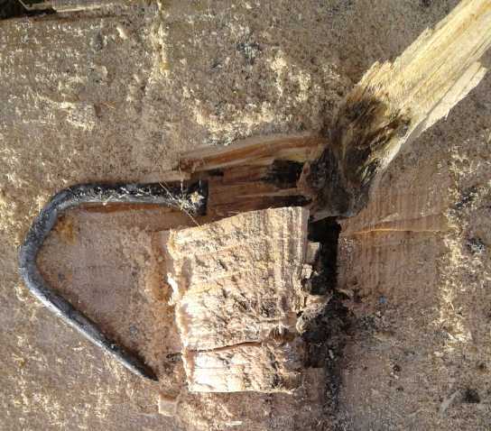 (12th) I cut another 6"
slab from the log, and managed to push it
aside. That went so well I decided to do another. About 4' along, and
6" inside the log, I hit a nail or something that wrecked my chain. I
don't think I could have detected metal that far inside even if I had
thought to try. A nasty expense for a job almost done! This is the
second tree near the house that has had nails, even in this country
place. It would have been over 6' up in the tree. That seemed rather
high for fence nails. Perhaps it was a hook for a clothesline or
humming bird feeder? The next question was, was there just one piece of
metal, one hook, or were others lying in wait? If it was just one, I
should be able to cut through 8 feet from the other end and just
carefully cut off the last bits of wood with a small chainsaw, then pry
it apart off the hook/screw/nail. It did seem like a spot a clothesline
might have been hung - quite a short clothesline, but there were no
other trees near the house that were more suitable for one. (It was a
straight nail. I bent it to pull it out of the wood. Naturally I had
been trying to rip the nail down its center. If I had just been cutting
through one section, the saw might have actually got through it. ...not
without lots of damage to the chain anyway.)
(12th) I cut another 6"
slab from the log, and managed to push it
aside. That went so well I decided to do another. About 4' along, and
6" inside the log, I hit a nail or something that wrecked my chain. I
don't think I could have detected metal that far inside even if I had
thought to try. A nasty expense for a job almost done! This is the
second tree near the house that has had nails, even in this country
place. It would have been over 6' up in the tree. That seemed rather
high for fence nails. Perhaps it was a hook for a clothesline or
humming bird feeder? The next question was, was there just one piece of
metal, one hook, or were others lying in wait? If it was just one, I
should be able to cut through 8 feet from the other end and just
carefully cut off the last bits of wood with a small chainsaw, then pry
it apart off the hook/screw/nail. It did seem like a spot a clothesline
might have been hung - quite a short clothesline, but there were no
other trees near the house that were more suitable for one. (It was a
straight nail. I bent it to pull it out of the wood. Naturally I had
been trying to rip the nail down its center. If I had just been cutting
through one section, the saw might have actually got through it. ...not
without lots of damage to the chain anyway.)
But if there were more pieces of metal, or if I went a bit
too far, I would just wreck another chain. Should I gamble it was just
one clothesline hook? How much is that wood worth? There was still a
lot of it. I could cut off 4+ feet and have a less than 8 foot log, but
I still might hit another piece of metal. I could cut off 6 feet and
have a 6 footer - not the most useful length boards! That would be fairly
safe. I could turn the log over and start milling again on the other
side?
Pulley and Link Belt Selections
(13th) I was sorting pulleys and I ran across a 2 inch V-belt pulley.
Then I realized the one I thought had ordered as a "1 inch pulley" was
really 1.5 inches. So it would seem that from the 5000(?) RPM skillsaw,
the 1.5" pulley turning a 9" pulley (6 to 1 reduction) made the band
run too slowly. Also it was too small for the V-belt to get a good grip
on, so it slipped when the going got tough. I estimate the variable
pulley I'm using is set to about 2.5 inches - it seems still larger
than the 2 inch pulley. (I may try the 2 inch pulley - it has the right
1/2" bore so it'd be easy enough to try out.)
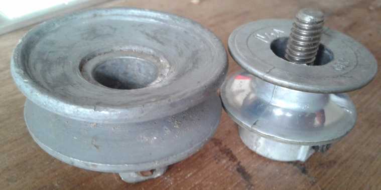 2 inch and 1.5 inch V-belt
pulleys. The 1.5 was
held on the skillsaw by that bolt.
2 inch and 1.5 inch V-belt
pulleys. The 1.5 was
held on the skillsaw by that bolt.
I also note here that when I went beck to the larger
pulley, I also soon went back to the link belt. It's much better than
the regular V-belt. I don't understand why they don't make regular
V-belts with grooves in them like the "variable transmission" V-belts.
Those would have to be better too!
Moving Along - Setting Teeth
(17th) Finally got back to it. I sharpened the band. But it didn't go
well. The saw was binding in the cut. I only cut one 6" wide by 12'
long board, and it was an inverted bowl across and not very straight
lengthwise. I tried to cut a second, but the cut curved up badly and I
gave up after a foot or so. The next day I gave myself a blister
bending a 'set' into the teeth with a small pair of pliers. (That feels
hard on that finger... well there's only 279 teeth, keep going and
finish it up!)
It was night and day difference! A thick stream of sawdust
sprayed from the saw, which cut freely at about 6 feet a minute. I cut
3 more boards in no time. After that it wasn't quite as sharp and the
cutting slowed down, but I still did 9 boards in well under an hour,
finishing the whole cant.
Moral: A tool working right works WAY better than one that isn't. Also
every time the band is sharpened some of the 'set' is ground off, and
it needs to be re-set after 2 or 3 or 4 (?) sharpenings.
Next Cant
Having had my chain re-ground (losing 1/2 its life) I cut
in from the other end of the log until I got near the metal thing. Then
the log kind of went "clunk" down on the cut and jammed it. I wedged it
open and pulled the saw back out. There was still over an inch of
"hinge".
I filled the gas tank, then I cut another 6" thick slice.
This one seemed to go well until about 9 inches from the end. There the
saw ran out of gas. Hard to believe - really? Normally I'd have stopped
it at the first sign of a sputter, but it was hard to believe it could
be empty, and with such a short distance I thought it might make it.
Not another inch!
I refilled the tank, but I wore myself out trying to start
it again. Typical! I hate gasoline powered appliances more and more the
more I use them. I know the best way to get this saw to start again if
it doesn't start with a few pulls or with removing the spark plug and
giving it a few cranks is to leave it a week. Then it will usually
start right up again.
I backed it off in the cut and cut to the end freehand with the
electric Dolmar chainsaw. The cuts weren't very straight. Anyway I had
- at long last - reached the bottom piece of the last section of the
last tree cut down in 2017. The rest was bandsawing. But I didn't get
there for the whole rest of November!
Skilsaw Chain Beam Saw
 Someone sent me a picture of a chain attachment for a handheld circular
saw, for "beam cutting". I'm not sure how practical it looks, but as
it's related, here it is.
Someone sent me a picture of a chain attachment for a handheld circular
saw, for "beam cutting". I'm not sure how practical it looks, but as
it's related, here it is.
One interesting feature is that like my bandsaw mill, it
uses a skillsaw as a motor to power something else.
http://www.praziusa.com/12-beam-cutter-model-pr-2700/
5 Blade Windplant - Windplant Ducts
Until the morning of the
6th no wind had blown to turn the windplant since October 23rd. Then it
made a few watts for a little while before stopping again. In the
evening it picked up and the next day there was a fair blast for a
while, creating figures of 45 to 65 watts. It was dark overcast and
that was almost as much as the DC solar power was making.
In fact, while typically things were quiet, there were
quite a few days with wind in November, and I would often see the
MPT7210A charge controller putting out 3, 15, 20 or 50 watts in the
wind. Occasionally it would hit 60s to 70 and beyond. On the 13th it
was blowing all day, with 40 to 65 watts being the most common
readings, and it went just over 100 for three brief readings. And it
would do it at times of day when there was little or no solar
collection. So it is by no means a useless appendage to the energy
system.
I don't notice the noise much. I do think it's quieter
than a 3-blade windplant. When the wind is blowing the waves are
crashing in and the level of noise is pretty high anyway. (This place,
for all its virtues, is a bit close to the sound of the ocean - a roar
on windy days - for my taste.)
On the 13th it all seemed worthwhile. Maybe I should do
some sort of venturi surround for it after all and get some higher
mileage out of it? But there wasn't much wind for the last 10 days of
the month.
Clarkson University Experiments with Windplant Ducts
Of course I'm not the only one to think of improving the
performance of a propeller type windplant. At Clarkson university they
have been experimenting and found they could literally double the
performance simply with a flaring exit to the fan, similar to the one I
drew last month as the exit to the venturi duct.
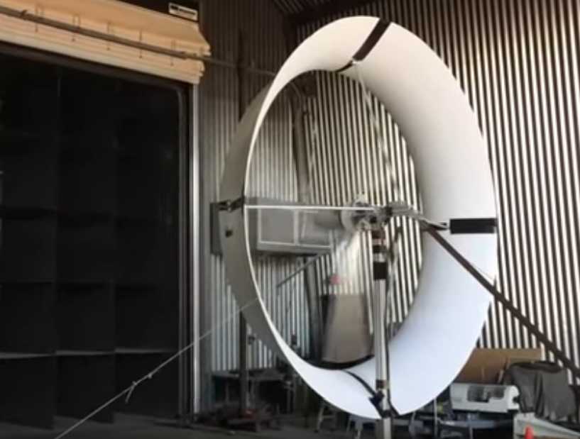 "Ducted" wind turbine (2017):
just a short
flared exit
"duct" doubles power -
"Ducted" wind turbine (2017):
just a short
flared exit
"duct" doubles power -
without doubling the price. What would a whole venturi duct do?
(On the left wall louvered fans blow controlled air at the unit under
test. Many of us only dream of having such test facilities!)
 Other windplant duct experiments
by Clarkson.
Other windplant duct experiments
by Clarkson.
Putting together the flared exit of the previous photo
and the "back end of a venturi" configuration of the
right side unit, they'd probably hit around 2/3 of the
effect of a complete front-to-back venturi duct.
(Or, they just might be doing better than I think
with those clever vane arrangements.)
https://www.youtube.com/watch?v=EXxA-RkwuRY
My
Solar
Power
System
Water Heater, Sprint Car &
Lithium Batteries
I noted last month that I had put a switch on the water
heater, hoping I could leave it on on dull days. Opening the switch
puts
the third heating element in series with the two already in series,
bringing the watts down from ~250 to ~160. When I did that the weather
doubled down and got duller and cloudier so that not even 100 watts was
being produced at midday. With the very weak NiMH dry cells battery,
turning on the water heater in either mode quickly brought down the
voltage.
By the 7th I was tired of nothing more than luke-warm
water and a sink full of dishes.
Last month I had made a DC/solar charging circuit to
charge lithiums without danger of any one cell hitting too high a
voltage, and connected to some 40 amp-hour blue colored lithium
batteries I had bought used about 4 years ago. I had always tried to
keep them charged up. Now at the end of October I tried to power the
solar system with them, and discovered that 3 of the 14 cells were
useless. They had voltage until one tried to use them, then they
instantly went to zero. A fourth cell was very weak. So there weren't
enough good ones to make 36 volts. This was unexpected. Perhaps they
were bad when I bought them? I might contrive to use some completely
different lithium cells in series to make up the last two, but for now
it seemed impractical to try and use them.
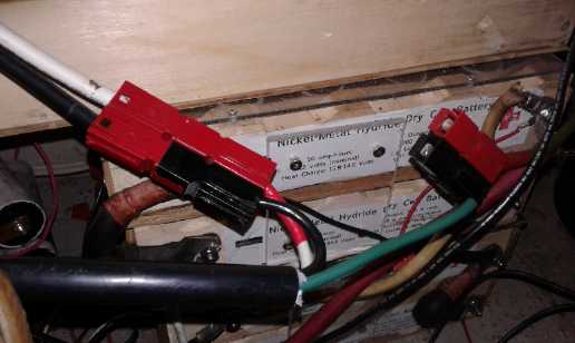
Other than the inaccessible 24 KWH Nissan Leaf battery,
that left the ~11400 rated watt-hours of lithiums in the Sprint car, at
36 volts. I thought I had made everything so I could connect the car to
the solar power with 70 amp Anderson connectors except the final
"extension cord" to connect them together. Connector in
car... Connector to panel... presently plugged into the NiMH batteries.
 I now made
that cord, unplugged the increasingly unsatisfactory NiMHes and plugged
in
the car/lithiums, and turned on the water heater with the full 260
watts
setting. The lithiums quickly dropped from just over 40 volts to
39-1/2, but only gradually continued down to 39.14. The next time I
checked, the water heater had shut off and it was back up to 39.68
(eventually to 39.81 and overnight about 40 volts). Time to wash dishes!
I now made
that cord, unplugged the increasingly unsatisfactory NiMHes and plugged
in
the car/lithiums, and turned on the water heater with the full 260
watts
setting. The lithiums quickly dropped from just over 40 volts to
39-1/2, but only gradually continued down to 39.14. The next time I
checked, the water heater had shut off and it was back up to 39.68
(eventually to 39.81 and overnight about 40 volts). Time to wash dishes!
(8th) Even with high capacity batteries that actually work one can't go
on too long without recharging them. For charging from 120 VAC I had
done the first two 6-volt chargers each on 2 series cells under the
hood last month. (putting out a constant 7.0-7.2 volts) Since I hadn't
yet done the rear, I connected my two Canadian Tire 'trickle' chargers
on the two 12 volt sections of the 36 volt total in the rear of the
car, ran a 120 VAC extension cord from the front to the back (under the
trim and next to the doors), and put an AC power bar in the back. I
plugged in all the chargers and put an AC power meter on the main cord.
The two old chargers in the rear drew just 15 watts each -
hardly over 1 amp at 14 volts. The new front ones started out at 135
watts,
indicating charging at almost 10 amps, and gradually dropped from
there. That's faster than the water heater discharges them. It's hardly
a guess which 12 volt section will be charged first! After a while
(well over an hour), the front was down to 45 watts while the rear two
were still at 15 each.
At first I still turned the water heater off at night, and
I
unplugged the chargers to the front of the car. I note that these are
not very well regulated - the voltage changes over time probably with
temperature. Furthermore the knob is much too easy to turn accidentally
an hard to get just where you want. Adapters with screwdriver 10 turn
trim pots - and better regulated - would be much better if they can be
found. A plus of these ones is that the AC input can be 100 to 240
volts. That means they could be plugged into a 240 volt J1772 car
charging
station - although there is no need or use for plugging them into more
than a
regular 120 volt outlet. (With 5 amp chargers at 36 volts it won't be a
fast charging car by any means. 10 or 20 amp power adapters would be
better if I could find them.)
Sprint Car & Solar Lithium Battery Chargers
(Now, should this be under batteries, solar power, or electric
transport?)
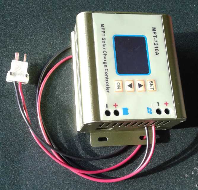
At this point, I had done nothing to recharge the lithiums
from the solar. I decided I should put an MPT7210A right into the
Sprint and connect it straight from the solar panels. (a second,
lighter extension cord.) That would be compatible with my DC lithium
charging circuit, and when I put the long-planned solar panel on the
car roof, it would be all ready to hook up. And since I had determined
that slow-charging 12 volt sections from solar was safe, I would use
just 3 DC to DC converters for the 36 volts. As I thought about it, I
would use two of them and adjust the 7210 to the exact voltage for the
uppermost section, 40.2 volts, from which the middle and bottom
sections would be subtracted leaving 13.4 volts per section.
How to connect? I wasn't going to hard-wire any part of a
car to a stationary wire. The solar panels were about 36 volts...
How about my 36 volt HAT connectors? I decided a 15 amp one should be
adequate. I had a couple of the 3D printed shells.
 I
took an absurd amount of time to wire up the plug - a
couple of hours. I had to make the pins by flattening a piece of #10
AWG wire and notching and drilling them per TE News 129, and then
soldering the wires
to them. It didn't go smoothly. I pulled out the wrong size pins in the
drawer but didn't realize it. Redo. For some reason the first drill I
tried
simply wouldn't drill through copper. Then the holes were too small for
the
wires. I soldered a wire on the wrong side of a pin and it mattered:
redo. I dropped a box of 100 tiny screws on the carpet. They wouldn't
go through the holes in the plastic shell so I had to drill those out
bigger.
I
took an absurd amount of time to wire up the plug - a
couple of hours. I had to make the pins by flattening a piece of #10
AWG wire and notching and drilling them per TE News 129, and then
soldering the wires
to them. It didn't go smoothly. I pulled out the wrong size pins in the
drawer but didn't realize it. Redo. For some reason the first drill I
tried
simply wouldn't drill through copper. Then the holes were too small for
the
wires. I soldered a wire on the wrong side of a pin and it mattered:
redo. I dropped a box of 100 tiny screws on the carpet. They wouldn't
go through the holes in the plastic shell so I had to drill those out
bigger.
I'm convinced now that the thing to do is to do injection
molds for CAT and HAT plugs and molds for putting clay in to make
porcelain sockets, as well as molds for wall plates and everything else
needed or useful, and to make stamps that will stamp out the various
pins and receptacles... and to manufacture and sell them to all the
places that sell solar and low voltage equipment. Maybe Amazon? That
way when anyone - including me - wants to do 12 or 36 volt wiring it'll
be simple and straightforward. Somehow no one else seems to have done
anything like it yet. (If they did and used my pin size and spacing
specs, I could just buy them and my problem would be solved.)
Next I thought about the steering diodes. The "car
alternator" diodes lost over .8 Vf. Recently I had uncovered
some 60 volt, 30 amp Schottky rectifier diodes I had lost track of.
(And I now put all my diodes into some plastic part drawers all in one
place.) These had actual part numbers so I could look up the specs!
They only lost .49 V max at 15 amps - only about 60% as much wasted
power - and even less since the MPT71210A only puts out max 10 amps.
(15th) I soldered four of them to little pieces of copper to screw to
battery terminals at the 12, 24 and 36 volt levels, with the anode
inputs from the DC to DC converter outputs. I mounted the MPT7210A in
the back of the car and ran a ground wire from under the hood to the
back.
That was about as far as I got. Owing to the time it took
to make a plug, I started thinking about making them easier to make,
and about how to produce them for sale. I enlisted Mike's help and we
at least came up with easier to make and use pins for the plugs and
almost equally simple "Z Fold" receptacles for the sockets. The small
writeup on that process is in "November in Brief".
Month of November Log of Solar
Power Generated [and grid power consumed]
(All
times are in PST: clock 48 minutes ahead of sun, not PDT which is an
hour and 48 minutes ahead. DC power output readings - mostly the
kitchen hot
water heater - are reset to zero daily, while the others are
cumulative.)
October 31st 2.98+.24, 888.72 => 2.78 KWH
[68579@17:30]
mostly cloudy, a bit of sun in the afternoon.
November
Solar: House+DC, Trailer => total KWH [grid power meter
reading(s)@time] Sky conditions
1st 4.00+.19, 889.33 => 1.82 KWH [68598@18:00]
light
overcast.
2nd 5.41+.56, 890.50 => 3.14 [55Km.chj.car;
68627@17:00] cloudy AM, sunny PM.
3rd 7.20+.42, 891.87 => 3.58 [68648@19:00] Mostly
sunny.
4th 8.08+.39, 892.65 - 2.05 [68666@17:30] cloudy.
5th 8.79+.11, 893.28 - 1.45 [68684@20:00]
cloudy.
6th 9.11+.19, 893.54 - 0.77 [68712@19:00]
Clouds rain and light winds (2-5 watts from windplant)
7th 9.82+.72, 893.84 - 1.73 [68732@17:30]
Dull,
windy (up to 45-65 W at one point from windplant)
8th 10.86+.50, 894.76 - 2.46 [85 Km,car charging;
68762@17:00] Mostly overcast.
9th 12.52+.05, 895.75 - 2.70 [60 Km,charging car; 68797@21:30]
Largely Overcast, a little sun.
10th 13.65,(.61*),896.58- 1.96 [68818@19:00] Mostly overcast.
(*Recharging lithiums on 36 volts system from wall not solar, so it
doesn't count
for solar collected.)
11th 14.95,(.95*),897.41- 2.13 [68835@19:00]
12th 16.40+.33, 898.37 - 2.74 [68849@17:00]
13th 16.77+.35, 898.87 - 1.22 [68864@16:30] (there's some wind
power in the DC .35, .62 KWH figures)
14th 18.00+.62, 899.69 - 2.77 [55Km,charging car; 68883@17:30]
Some sun.
15th 19.80+.07, 901.07 - 3.25 [85Km,ChjdCar; 68914@22:30] Quite a
bit of sun. (But quite short days now!)
16th 20.16+.15, 901.33 - 0.77 [55Km,Chj; 68931@17:30] Clouds
& rain.
17th 21.37+.42, 902.33 - 2.63 [68950@18:00] some clouds, rain,
sun.
18th 01.83+.37, 903.58 - 3.45 [68968@19:00] mostly sunny (power
fail during night)
19th 03.47+.30, 905.28 - 3.64 [68983@18:30] Sunny!
20th 04.74,(1.28),906.14-2.13 [69000@21:00] Some sun. I ran out
all the hot (hardly warm) water in the sink because it stank, until it
ran completely cold. Then I turned on the heater and later with water
that didn't stink I did a good load of dishes. Thus the high usage -
which came mostly from the car lithiums, from the power grid. I turned
down the temperature a couple of times, but if the water is in the tank
a couple of days, (ie if I don't use most of it, daily) it starts to
stink. (sulfur?) I know the well water is mineral rich, but why does
the kitchen hot water smell, but the water in the main hot water tank
tank never does? And I con't remember any smells last summer when I put
the tank in.
21st 05.64+.35, 906.99 - 2.10 [69026@17:30] Mainly sunny, rained
a bit anyway (sun from way south, rain from above.)
22nd 05.68+.01, 907.01 - 0.06 [85Km&Chjd; 69064@23:00] Clouds &
Rain. Holy Nothings! Could a day's collection get any closer to
'gooseegg' than that?!? From a full 15 KWH in summer that's ~.04%. One
could do 100x better in space way out near Jupiter! PS: One can see I
didn't turn the kitchen water heater on this day - just lights on the
DC power.
23rd 06.51+.01, 907.52 - 1.35 [55Km&Chjd; 69076@17:30] Mor cloudz
and rain. Left KHW off again.
24th 08.21,(1.04),908.71-2.89 [69098@24:00] Sunny, rain before dark.
Left KHW heater On, on the car/lithiums.
25th 09.77,(.60),909.88 - 2.73 [89109@17:00] Mostly sunny.
26th 10.58,(.62),910.81 - 1.74 [89131@17:00] Snow, then sunny.
27th 13.71,(.92),912.35 - 4.67 [69153@16:00; 55Km,ChgCar] Sunny. (Extra
sunny - No jet trails)
28th 15.33,(.14),913.18 - 2.45 [69184@19:30] Mainly sunny.
29th 17.33,(.18),914.60 - 3.42 [90Km,Charging; 69205@17:00] Sunny. (Sky
full of jet trails by sunset)
30th 18.12,(1.11),915.01-1.30 [55Km,Charging; 69232@17:00; 50Km,Chj.]
Not sunny.
December
01st 18.84, (.71), 915.41 - 1.12 [69276@18:30] Even more not
sunny.
02nd 19.58, (.63), 915.84 - 1.17 [55Km,Chjd; 69306@21:00] Clouds and
Rain.
Daily-
KWH- # of Days (Nov)
Made
0.xx - 3
1.xx - 8
2.xx - 12
3.xx - 6
4.xx - 1
5.xx -
6.xx -
7.xx -
8.xx -
9.xx -
10.xx-
11.xx-
12.xx-
13.xx-
14.xx-
15.xx-
16.xx-
Monthly Tallies: Solar Generated KWH [Power used from grid KWH]
March 1-31: 116.19 + ------ + 105.93 = 222.12 KWH - solar [786 KWH -
used from
grid]
April - 1-30: 136.87 + ------ + 121.97 = 258.84 KWH [608 KWH]
May - 1-31: 156.23 + ------ + 147.47 = 303.70 KWH [543 KWH] (11th
solar panel connected on lawn on 26th)
June - 1-30: 146.63 + 15.65 + 115.26 = 277.54 KWH [374 KWH] (36V, 250W
Hot Water Heater installed on 7th)
July - 1-31: 134.06 + 19.06 + 120.86 = 273.98 KWH [342 KWH]
August 1-31:127.47 + 11.44+91.82+(8/10)*96.29 = 307.76 KWH [334 KWH]
(12th panel connected on lawn Aug. 1)
Sept.- 1-30: 110.72 + 15.30 + 84.91 = 210.93 KWH [408 KWH]
(solar includes 2/10 of 96.29)
Oct. - 1-31: 55.67 + 13.03 + 51.82 = 120.52 KWH - solar
[635 KWH - from grid]
Nov. - 1-30: 36.51 + 6.31 + 26.29 = 69.11
KWH - solar [653 KWM - from grid]
9
month total March 1 to November 30: 2044.50 KWH made; [4683 KWH
consumed
from grid]
Things Noted
* At some point in October I gave up trying to charge the car at 1500
watts during the day in order to use power from the solar, and just
used the 3800 W charging station. There just wasn't enough of it for it
to help. What solar power there was would have been taken by other
loads around the house anyway - easily by the 250 W travel trailer
heater and the 175 W(?) LED grow lights for the indoor winter garden.
And the sunny hours were too short to bother even if there had been
enough power during
the day.
* On the 10th to 13th (and various other days) I didn't drive anywhere.
This is reflected in
markedly lower electrical consumption on those days.
* Owing to the low winter collection I looked up Stirling engines (see
article below). I think I can make a better one for the woodstove,
"sort of" a low pressure steam engine! A generator would be attached.
100 Watts?
Woodstove
Alternator
with
Stirling Steam Engine?
(apologies for poorly written rambling article. I want to get this
newsletter out tonight!)
(22nd) In the winter weather and low sunlight, and with the windplant
only very occasionally firing up, I thought again occasionally about
using the woodstove for generating electricity, and how the seemingly
promising TEGs (thermoelectric generators - sort of a special Peltier
module - had in the end seemed like "not much bang for the buck" and I
didn't build it. I thought that boiling water on the stove and running
a steam turbine could give a heck of a lot more power. But realisticly
the top of the woodstove is rarely hot enough - unless the steam was in
some sort of closed loop in a partial vacuum to reduce the temperature
water would boil at. That would make it a very complicated project.
I have also
thought off and on about Stirling engines, also called "external
combustion engines", invented by Robert Stirling in about 1816, after
Guillaume Amontons' "Fire Mill" hot air engine in 1699. (over a century
earlier!) They run off any amount of heat, in fact off the temperature
difference between one end and the other. I didn't understand how they
worked, and owing to the mechanical difficulties of constructing a
piston sliding in a cylinder they didn't seem like anything I wanted to
get involved with. (I was having more than enough mechanical trouble
with building "too flimsy" or "insufficient" torque converters.)
I wandered off to youtube
and found that "MyfordBoy" had made a couple of very elementary (not to
say "Mickey Mouse") "Beta-type" Stirling engines. They spun madly,
admittedly with no load. To do that with just a candle for power, they
must have very low friction and be quite efficient. An old CD was the
flywheel. Furthermore, his videos showed just how to make them from
start to finish. Surely even I could make one!
The most notable feature was that the power piston was
replaced by a diaphragm. The material was latex from single use gloves,
or balloon rubber. This seemed to me to be the key: no piston with
rings to make friction. That was why they worked well - not to say why
they worked at all. Technically the round piece of wood in the center
of the diaphragm with the rod connected was still a piston. It just had
the diaphragm for a seal instead of rings sliding up and down in the
cylinder. It made a perfect seal that was also simple to make with no
high precision parts required. Cool!
Could this clever design be made in a larger version with
some real power, say with a car tire inner tube for a larger diaphragm?
With an aluminum base to sit on and take heat from the woodstove, and
an aluminum heatsink radiator up at the top, similar to the animation
from Wikipedia? This seems to me to have great potential to turn a
generator.
I figure the target is around 50 to 100 watts with a fair
fire in the stove. (I hope that's not too optimistic.) This is much
better than a 100 watt solar panel because it would run all day and
night: eg, 2.4 KWH of power per day from 100 watts. (That's more than
I'm getting many days in midwinter from a dozen solar panels total
rated 3.4 KW.) It should also be sufficient to charge a battery to
power a few LED lights and run an inverter to power a freezer or fridge
in a power outage.
So I conceive of something akin to a big "coffee
percolator" (anybody remember those?) sitting on the stove, with fins
around the top and a substantial flywheel spinning above it. The bigger
the thick aluminum base, the more heat it would collect from the stove.
The bigger the heatsink fins, the better it would dissipate the heat at
the top end and together the more power it could make. The moving parts
had to be large and robust enough to make good use of the temperatures
thus provided.
MyfordBoy's Stirling engines, like the others I looked at,
had to be started with a spin by hand. The flywheel then carried them
through the non-powered parts of the stroke. Self-starting would be a
plus, but since one has to feed wood into the stove anyway, giving it a
spin would be an extra little thing to do after lighting a fire.
Then the generator could either be a separate unit, or
more simply the flywheel itself could have magnets on it and there
could be some coils installed in something around the outside. With the
materials I already have, I would just make the flywheel an axial flux
magnet rotor and make it a highly efficient Pigott type alternator.
I could actually see this being a viable commercial
product! Why does no one seem to have done it this simple way before? I
guess the way to find out is to build one and try it, and see how well
it works!
(29th) I occurred to me that the way to make the big cylinder was a
flat aluminum plate welded to an aluminum ring. Then it occurred to me
that sounded like the bottom of a pan. I looked around and found an old
aluminum pressure cooker. I'd never used it but still it seemed like a
waste to cut it up. I decided to try the thrift shop the next day.
But then it occurred to me that it would be even better if
the heat from the bottom wasn't being conducted through to the top.
What would one use as the edge material if not metal? And how would it
be bonded to the bottom plate?
Wikipedia Image Caption:
Beta-type Stirling engine. There is only one cylinder, hot at one end
and cold at the other. A loose-fitting displacer shunts the air between
the hot and cold ends of the cylinder. A power piston at the open end
of the cylinder drives the flywheel.
How it works
------------
Referring to the animation, there is the power piston (upper moving
part), and the displacer (lower).
0 degrees rotation: The displacer rises. This means most of the air in
the cylinder is at the bottom, where it is warmed. Warming air must
either expand or the pressure will rise. First the pressure rises.
90 degrees: The increased air pressure pushes the power piston (or
diaphragm) upward and the warmed air expands, losing pressure and
returning to 'medium' temperature as it does so.
180 degrees: The displacer now moves down to the bottom. Most of the
warmed air is now above the displacer and exposed to the cooling fins.
As it cools it must either contract or the pressure will fall below the
outside air pressure. Initially the pressure reduces.
270 degrees: The relative vacuum of the contracting air pulls the power
piston downward. The air volume shrinks and the air temperature goes
back to 'medium'.
The two arms and the rotating wheel keep everything in sync. The wheel
is also a flywheel, keeping everything in motion through the unpowered
parts of the cycle.
Design features suggest themselves. The larger the hot bottom area, the
faster the air will heat and the greater the power will be. It probably
doesn't need to be very tall, so a cylinder and displacer much more
short and squat than the animation - just as MyfordBoy's are
configured. The displacer should be as lightweight as possible, perhaps
a hollow "tuna tin" sort of shape only bigger. The "power piston"
diaphragm and the cylinder it's in(?) needn't be anything like as big
as the lower part. The smaller it is, the faster and farther the rising
and falling air pressure will move it and the higher the RPM. Larger
will be lower speed and more torque - but the same theoretical power,
since the power comes from the heat from the stove and the cold from
the radiating fins.
A late thought came to me at 2:30 AM on the 25th (or is that an early
thought?): The top surface of a woodstove often operates right around
the boiling point of water or a little over it. If a little water was
placed in the cylinder, then while the displacer was up, the water
might boil (a little or a lot) in the bottom. This phase change would
cause much more pressure than just expanding air. Then when the
displacer was down, the steam would condense on the radiator and fall
back down as water drops, causing a lot of contraction and vacuum. It
would have much more power for its size. Maybe that would make it some
sort of steam engine after all! Some details have to be thought
through...
Trust me to start out with the idea of just copying
something, and to soon be wondering if and thinking how significant
improvements might be made to the whole idea! What's the real point of
taking on another project if it's not going to be a "world's best" or
"world's first" or something? Other than to have a reliable source of
winter electricity, of course.
By the 27th my idea was that it would be a very shallow
cylinder with a displacer like a pancake. The whole bottom would be
sitting on the woodstove, and much of the top would have cooling fins.
There would be a slot in the mechanism to give it a little slack. The
idea of that would be that it would hit the bottom of the short
cylinder, pushing all water out of the way, and sit there for part of
the stroke. Thus the water would be out of contact with the woodstove
surface for a certain period, say 1/4 of the cycle, and would be
cooling and condensing, sucking the power "piston" down.
When the displacer lifts off the bottom, the water rushes
in and starts to boil, The expanding steam and air pushes the power
piston out again. With a spring the displacer could be made to rest at
the top of the cylinder for 1/4 of the cycle, blocking access by the
steam to the cooling fins.
So the cycle is:
1. The displacer reaches the bottom and sits there, covering over the
heat plate from the woodstove, and no more water or air is heated. The
steam and air cools on the surface inside from the cooling fins on top
and the steam condenses, dripping down onto the displacer.
2. The cooling air/steam vacuum causes the power piston/diaphragm to
pull down while the displacer still rests on the bottom.
3. The falling piston turns the flywheel until the displacer starts to
rise. It goes to the top as the piston crosses the bottom of its stroke.
4. With the displacer at the top, the steam has no access to the top
surface just inside the cooling fins, but the water at the bottom
rushes in and boils, heated by the hot surface sitting on the woodstove.
5. The boiling water/steam/air expands and pushes the power piston up.
6. The rising piston turns the flywheel until the displacer starts to
descend. It goes to the bottom as the piston crosses the top of its
stroke. Then the cycle repeats.
(28th) In fact, why have the displacer be driven by the flywheel at
all? Ideally it's either at the top or at the bottom all the time. It
could be lifted by activating a solenoid, with the switch on the
flywheel. Or else, it should go quickly to the top or bottom at the
half way point on the flywheel and sit there for almost 180 degrees of
flywheel/power piston travel. If mechanically driven by a cam on the
flywheel, a slot instead of a hole would allow it to rest on the
bottom, but a spring would have to be used to allow it to rest on the
top as the cam continued upward. Actually for both those reasons, the
displacer and its mechanism should be as light as possible consistent
with being able to keep up to whatever RPM is attained, since lifting
it, and compressing the spring toward the top of the stroke, both
require work from the piston.
The displacement cylinder with its bath of water need only
hold a small volume. The displacer would be a thin pancake and the
cylinder would be a thicker hollow pancake that holds it. Most of the
steam would be forced to move into and out of a smaller cyclinder above
it with the power piston or diaphragm in it. It should also be largely
a heat insulator rather than a heat conductor. Using a piece of 1/4"
plywood in the prototype suggests itself.
As I think about it, any Stirling engine would work better
if its displacer sat at the bottom or top through most of the stroke. A
down side might be more noise from the rapid (even sudden?) stops and
starts of the displacer instead of a gentle sine wave motion?
Just what I needed, another project! I talked about it
with my next door neighbor. He's a great project doer, and he might be
willing to do the work and make one for himself if I show him what to
do. And there's another person in Victoria for whom this sort of
project would be just up his alley. If I do a few experiments and most
of the designing... and probably make the actual generators... these
people might like the fabrication project. But it seems worthwhile.
Millions of people who burn wood could make sufficient free power for
their fridge, LED lights, charging devices and batteries and so on in
winter if they're off-grid, or during power outages.
Before sending this newsletter I had collected an aluminum
pressure cooker from my own storage as a test cylinder that would hold
pressure, and a 10 inch aluminum frying pan with straight sides - a
perfect shallow cylinder - from the thrift shop, and some "happy
birthday" balloons.
Electricity Storage (Batteries)
Turquoise
Battery
Project:
Long
lasting,
low
cost,
high
energy
batteries
I did a few little things,
but mostly I gave battery making a rest for November. I was getting a
bit burnt out on them and I needed to do some other things - finish
milling my spruce and do a bit on the other neglected projects.
Zinc Protection
Near the start of the month I ran a few more tests on the
nickel-zinc cell, and added some salt. It didn't have very much
capacity or current and the salt didn't do much for it. Then after a
few days, it quit working entirely. It seemed familiar... I could only
think of one thing that would cause such a sudden failure.
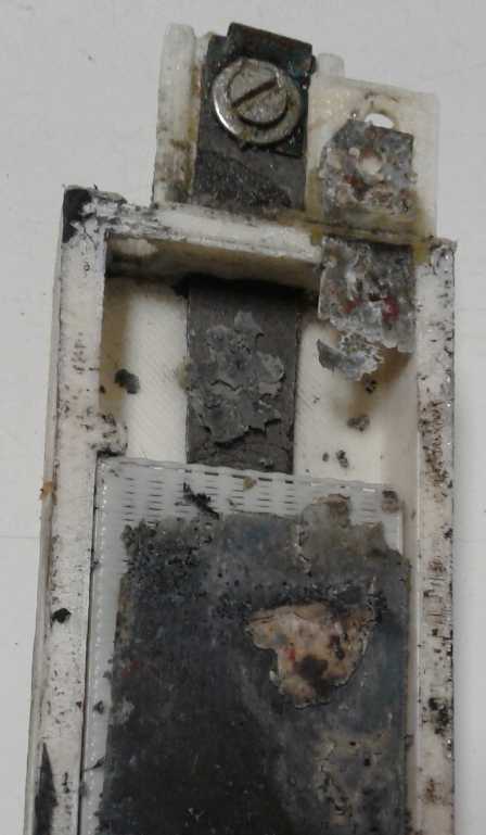 (17th) I [finally] pried
the cell open. As anticipated, the zinc
terminal tab had turned to brittle zinc hydride up at the surface of
the
liquid where the hydrogen bubbles would collect, and finally broken
off. In fact, 3/4 of an inch of it was missing, with a chunk lying
loose inside. Of course: the zinc tab had no jell and no zircon to
raise the hydrogen overvoltage to prevent gassing.
(17th) I [finally] pried
the cell open. As anticipated, the zinc
terminal tab had turned to brittle zinc hydride up at the surface of
the
liquid where the hydrogen bubbles would collect, and finally broken
off. In fact, 3/4 of an inch of it was missing, with a chunk lying
loose inside. Of course: the zinc tab had no jell and no zircon to
raise the hydrogen overvoltage to prevent gassing.
I had painted the tab with polyurethane spray paint to
protect it when I made the electrode, but I noticed when I opened the
first cell it was in that the paint was disintegrating in the alkali
and
loose chunks of it were drifting around. (Just a couple of flakes of
red remain.) It would seem protecting the
zinc is
indeed necessary, but that PU isn't the thing to do it. Perhaps the tab
needs to be electroplated with some other metal - maybe lead? Tin?
Copper? Or dip it in melted plastic? In epoxy? I'll try a couple of
other paints first.
(What was it my brother said on the phone again? He knows
a lot more chemistry than I do. But not specifically electrochemistry -
more organic chem.
I remember when I tried to make a transparent acrylic battery case and
it swelled and cracked. To him it made sense that polyacrylic acid
(PAA) would become a gel in alkali.)
Now that I'll be making a new electrode and a new cell,
maybe I'll try that Minwax Polycrylic that I bought for the ground
effect craft. Acrylic is something different than polyurethane. Maybe
it'll form a protective gel?
But there may be another factor at work here... I've been
using "roof moss killer" zinc because it was the only sheet zinc I
could find in Victoria. I've wondered how pure it is, but I've managed
to keep that thought out of my mind for a long time now. But why is
there black crap when I etch it, and black crap left over from a
sacrificial zinc electrode when I'm electroplating? Whatever it is, it
says it can't be pure zinc.
(27th) I got on line and found some "high purity zinc sheet" from 3
different stores on Aliexpress. First 20 pieces that were 100x100x
.2mm. Then I thought it would be nice to have some bigger ones to make
larger cells, and ordered another five sheets, 140x140x .2mm. That was
as big as they came. Then I decided as long as I was experimenting to
try some that was even thinner. It came in a roll 100x1000x .1mm.
That's probably too thin, but I'll see if it gets holes in it or has
any other problem. It all came to almost 50$c. I hope there is a
cheaper wholesale price somewhere for manufacturing. It's likely to
take the better part of a month to arrive. But it just *might* solve
the problem... or maybe even 2 or 3 problems.
Case Sleeve
One thing about gluing cases closed: it made it hard to
get in and see what was happening. Busy as I've been, if a tab had
broken off in an open cell I'd have seen the problem right away. In
fact I'd have seen it getting brittle beforehand. I got the idea to
make a close fitting ABS box that the whole cell slid into. Not only
would it not matter if the case leaked, but maybe I wouldn't glue the
cover shut.
I cut the plastic pieces, but I didn't get it glued
together. Just as well as another idea came to me. - read "Layout"
farther down.
Positive Electrode
The nickel oxides 'trode hadn't performed very well, in
spite of being an old and well known chemistry. It shows that it is my
technique that must be in some way faulty. It did however work,
equally in straight alkali (KOH) and with salt (KCl) added. That was to
be expected from the pourbaix diagram, but after seeing that lead oxide
didn't behave anything like I expected in alkaline pH, it was an
experiment that needed to be run. And it now
seemed to be verified.
For the poor performance, poor conductivity comes to mind.
It only had 5 wt% conductive
carbon black additive. Doubling it seems like a good thing to try.
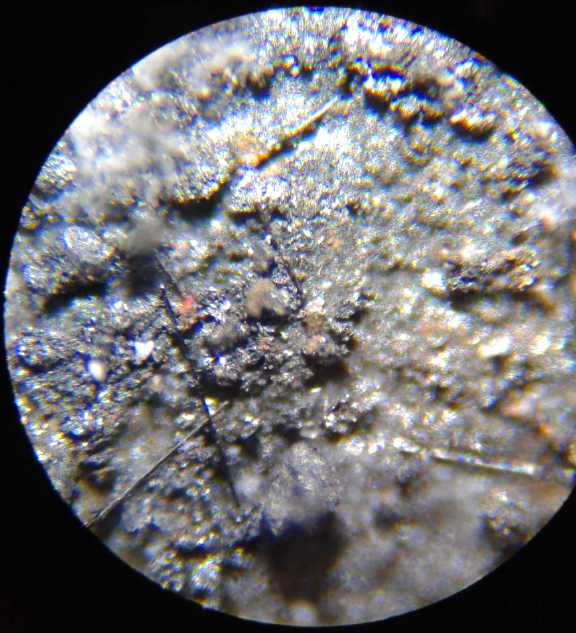 My NiOOH electrode at 200x.
The open side surface is a bit lumpy,
and a few fine carbon fibers protrude.
The side against the current collector was smoother.
There is a bit more light color than in the com-
mercial electrode, which I attribute to the gel.
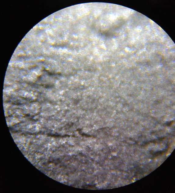 The smoother NiOOH electrode from
a Tenergy
NiMH dry cell at 200x.
The smoother NiOOH electrode from
a Tenergy
NiMH dry cell at 200x.
The fine grains looked pretty similar.
(Rats, how did both photos of it turn out so fuzzy?)
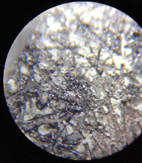 The Tenergy metal hydride
electrode at 200x for
contrast.
The Tenergy metal hydride
electrode at 200x for
contrast.
The surface was against the fibrous separator sheet.
Calcium-Copper Oxide
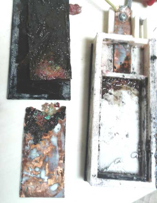 And then
there's the calcium-copper oxide current
collector idea. Copper sheet is a much better conductor than graphite
sheet, and even with an oxide film on it it might be a substantial
conductivity improvement. The other (MnO2-Zn) cell had sat idle for a
month. The voltage of MnO2 was high enough to oxidize the copper sheet
behind it. Now I took it apart too, to see what it looked like. (Again
if it wasn't glued shut I'd have done so a while ago.)
And then
there's the calcium-copper oxide current
collector idea. Copper sheet is a much better conductor than graphite
sheet, and even with an oxide film on it it might be a substantial
conductivity improvement. The other (MnO2-Zn) cell had sat idle for a
month. The voltage of MnO2 was high enough to oxidize the copper sheet
behind it. Now I took it apart too, to see what it looked like. (Again
if it wasn't glued shut I'd have done so a while ago.)
The copper tab was corroded off. But interestingly, it was
mainly where it went through the slot into the upper part of the cell.
Possibly all the calcium was scraped off it at that point during
assembly, leaving unprotected copper. And then oxidation had eaten in
from the bad edges thus created. With the MnO2 electrode brick removed,
there were also a couple of areas, "lines", of black copper oxide next
to the edges near the bottom of the copper foil. But on the whole the
main surface looked uncorroded, front and back. That seemed very
promising.
So it looks like the idea might work and make a
higher
conductivity cell, but it needs further study. Perhaps there is a
method to fully and completely coat the copper sheet with calcium
before inserting it into the cell?
Or... Gold Plated?
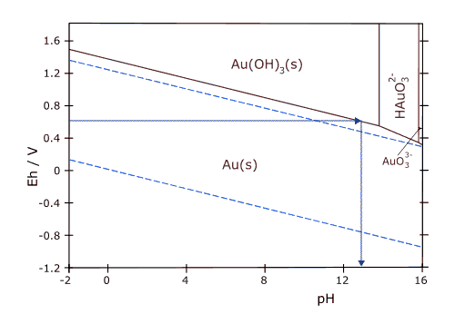 If that
doesn't work, there's something that has a very good chance: gold
electroplate the copper. The reaction voltage of gold to gold hydroxide
(Au(OH)3, ~+.6V @ pH 13) is higher than Mn2O3 to MnO2 (+.25V). So a
gold plating wouldn't oxidize. That's assuming I'm using nickel
manganates because they should recharge properly, and that their
reaction voltage is that of manganese dioxide. (Or else that I've found
a way to properly recharge to MnO2.)
If that
doesn't work, there's something that has a very good chance: gold
electroplate the copper. The reaction voltage of gold to gold hydroxide
(Au(OH)3, ~+.6V @ pH 13) is higher than Mn2O3 to MnO2 (+.25V). So a
gold plating wouldn't oxidize. That's assuming I'm using nickel
manganates because they should recharge properly, and that their
reaction voltage is that of manganese dioxide. (Or else that I've found
a way to properly recharge to MnO2.)
The reaction voltage of gold to hydroxide is about the
same as nickel hydroxide to oxyhydroxide, so it would probably oxidize
in a NiOOH electrode. But gold is such a heavy element this oxide might
well remain solid and bonded as a one molecule thick layer protecting
everything underneath - just like with titanium or aluminum (at neutral
pH), and nickel at pH 14.
Gold costs money, but it doesn't have to more than
angstroms thick. (What's an angstrom again?) (If it was cheap one might
have a gold-oxide/metallic gold powder-paste electrode and the cell
would be a solid 1.7 volts or so with amazing current density. I don't
even want to try that out - what would I do if it worked really well?
It is known to work well with copper-oxide/copper, gold's column 11
relative on the periodic table, but with copper the reaction voltage is
so low that even with zinc for the negative, the cells are less than
one volt.)
Now... where was my old bottle of Caswell Plating gold
electroplating solution? A fairly diligent search didn't uncover its
hiding place, but the next day (27th) I had another look and unearthed
it in with cans of spray paint.
Now... would it still work, or did I need to get something
new? There were some almost microscopic bits of gold around the rim and
on the bottom. With a stainless steel anode the brush plating didn't
seem to work. (28th) I found a tiny piece of gold, soldered it to a
piece of copper wire as a rod, and tried with that. No difference. But
some very few little streaks of dark color had appeared with both.
One last thing... I tried heating the solution while
stirring, to maybe 70°C. Then I tried again witht he gold anode. A
few more dark streaks. I poured the 30 cc of liquid into a beaker and
tried plating in this bath, again with the gold anode, at a very low
current. This produced a more uniform dark coating.
I finally decided that the dark coating was probably the
gold, but that it was so thin I was also seeing the copper underneath,
and they were subtracting colors. Even when the solution was new I had
had a hard time getting a thick enough coat to make it really look
yellow. "A few angstroms thick", I said. Was it enough to protect the
copper underneath? Or did it mean there was some gold and some bare
copper? Once there was any hole in the coating, the copper would
gradually dissolve in the cell.
Or maybe the combination of gold oxide (if it formed) and
calcium hydroxide would react together and form the desired
non-corroding surface on the copper?
I left the piece in the plating solution overnight, but it
didn't change color. I finally decided the coating probably wasn't
really gold but some impurity, and that I should get some real tank
immersion gold plating solution. Let's get enough gold on there to make
it at least vaguely yellow! I ordered it on the 29th, again from
Caswell Canada.
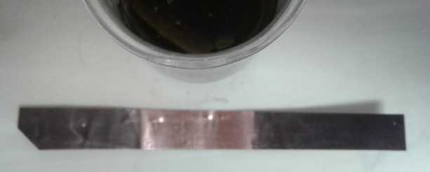 That purple-black color don't
look much like
gold to me.
That purple-black color don't
look much like
gold to me.
I thought shipping said "Fedex". (There was no other
option. What have people got against the post office? I'm sure it's
much better than it used to be. I haven't lost anything in the mail in
about 13 years.) The receipt however said "UPS / Purolator 1-4 days
depending on location". If they sent it UPS I may not get it in 2019!
The alternative to finding a sheet metal or
coating/plating that won't oxidize of course is to use sheets of
graphite. That has higher surface resistance and hence lower current
capacity than a metal. But it does work, and it's not entirely
incompatible with the flat cells idea if the corner tab bends up
gradually as a ramp instead of making a sharp fold straight up.
Layout
I've been making skinny batteries that always want to fall
over.
It has occurred to me I that if the current collectors are
metal, I can have them lie flat. The connection tabs can be bent upward
to come through the case at the top. In fact, the corner can be slit
and a tab bent up without needing any extension to the square or
rectangular sheet of metal. If the bottom electrode was slit and bent
one way and the other the other way, that would just leave a little gap
with no electrode in the corner where both terminals are.
And that could form a little reservoir in that corner,
where one could open a top plate or cap on to check the level and add a
little water into. And as long as the cells aren't to hold pressure,
there's essentially no size limit.
They could for example be 12 by 12 inches. That would give
about 850 square centimeters. If one could get 200 mA/sq.cm, that would
be around 170 maximum amps. That's for a single layer cell less than
1/4 inch tall inside, which might also hold around 30 or more amp-hours
depending how thick the electrodes are. A stack of 8 cells for 12 volts
might be 3 or 4 inches high.
(It's tempting to think of sticking the electrode plates
themselves to an edge frame so they form the top and bottom of the
cell, instead of having a plastic top and bottom covering them. That
would be great if and only if one could keep them from leaking around
the edges. I think I won't try it.)
(27th) I trimmed my idea down to about 7 x 7 inches for now, realizing
that that's about as big as the 3D printer can handle. Still somewhere
around 50 maximum amps and 10 amp-hours of storage.
(28th) On ordering pure zinc I reduced that yet again for now -
the biggest sheets I could find were 140x140mm, or 5.5x5.5 inches.
100x100mm (3.94") were cheaper and I ordered some of them too. So much
for 12x12 inches! 5.5x5.5" and 4x4" are only 21% and 11% as large. 7x7"
would have at least been 1/3. Then again, perhaps 100x50mm or even
50x50mm is a good size for testing.
Lithium
Battery
Charging (120 VAC Power)
Note: Where to put it? I have moved lithium charging with DC power to
fall under the heading of My Solar Power System under Electricity
Generation. Hopefully I'll have finished writing about the AC
charging soon.
I connected the
Sprint car to the 36 volt solar DC supply. While connected it took over
heating water in the kitchen and running the DC light
at night. The car is "36 volts" (really closer to 40) with 300
amp-hours composed of three 100
amp-hour lithium cells in parallel at every voltage level. Call it 38 V
* 300 AH = 11,400 watt-hours.
Having installed the two 120 VAC source chargers in the
lowest 12 volt section, set to provide 7.0 volts, I measured the
voltages on each cell shortly after charging with the two 6 volt
chargers. At
the (nominal) 0 volt, 6 volt and 12 volt levels cells A, B and C were
connected together, so the only places they could be different were at
the 3 and 9 volt levels. The notorious lithium imbalances between cells
are plainly evident in each pair of cells. (Are the ones at 3.28 volts
actually fully charged? The AC line current supplying the chargers
dropped way down, so presumably they must be. What happens if both
cells in a pair refuse to rise above 3.28-3.32 volts? I guess they just
keep drawing current?)
Nominal
Voltage
Level
|
Battery "A"
Cell Voltages
|
Battery "B"
Cell Voltages
|
Battery "C"
Cell Voltages
|
9-12 V
|
3.59
|
3.57
|
3.44
|
Upper 6 V
|
6-9 V
|
3.35
|
3.36
|
3.51
|
Charger
|
(Cells connect-
ed together at 6
volt level.)
|
3-6 V
|
3.28
|
3.61
|
3.28
|
Lower 6 V
|
0-3 V
|
3.66
|
3.32
|
3.66
|
Charger
|
I will remark that I'm quite disappointed in these
particular adjustable power adapters. First, multi-turn screwdriver
trimpots would be far better than the single turn pot with a knob on
it. First they are incredibly touchy, hard to set the voltage on. Then
the slightest touch, accidentally brushing the knob, changes the
voltage. Unless it's being used as a cheap lab power supply, whatever
you're using it for you want to set the voltage to some value and have
it stay there.
My second complaint is the same problem: the voltage
doesn't stay where you put it anyway. The load and temperature
regulation are terrible. In some applications going up or down a volt
(or considerable portion thereof) may not matter, but in others it does
- it sure does in battery charging.
Nor am I fussy about them drawing current from the
batteries when unplugged. The "car alternator" diodes I put in to
isolate them drop over .8 volts - wasting over 10% of the charging
power. (I should probably look for some Schottky diodes with a lower
drop.) And when the batteries are charged and current is reduced, the
drop decreases, raising the voltage to the cells just when it's not
wanted any more.
I can't see these as being reliable for unattended lithium
car battery charging. I'm sorry I bought a dozen. Apparently I should
have started with two and checked them out. Next time I'm shopping on
line I'll be on the lookout for something better. OTOH these were the
best I could find when I was looking - I may just have to make do.
http://www.TurquoiseEnergy.com
Haida Gwaii, BC Canada