Turquoise Energy News #139
covering
December
2019 (Posted January 5th 2020)
Lawnhill BC Canada - by Craig Carmichael
www.TurquoiseEnergy.com
= www.ElectricCaik.com
= www.ElectricHubcap.com
Month In "Brief"
(Project Summaries etc.)
- 12/36 Volt DC CAT/HAT plugs and sockets - Woodstove Steam Engine
Generator - Power outage and running 230 V well pump on an inverter -
Ground
Effect Vehicle - New Chemie Batteries - A Solar Kayak
In
Passing
(Miscellaneous topics, editorial comments & opinionated rants)
- Hair Loss: the Demodex Folliculorum Mite / Helpful
Methods for Keeping (& Restoring?) Hair - Social and
Political
Evolution - Small Thots: "5G"≠"5 GHz", Supercorder, Nuclear waste -
Disaffected Generation - How food shortages anywhere become a global
problem - ESD
- Detailed
Project Reports
-
Electric
Transport - Electric Hubcap Motor Systems
* Ground Effect Vehicle (Still the Prototype 1/4 scale R/C
Model... continued)
* EV Transmissions: 5 to 1 planetary gear for the Miles
electric cargo truck
Other "Green"
Electric Equipment Projects
* HAT & CAT Plugs & Sockets
Electricity Generation
* My Solar Power System: - Monthly
Solar Production log et cetera - Notes.
* Woodstove Stirling Engine "Carmichael's
Woodstove Engine" (& generator)
- Rapid design metamorphosis - Design Arrival: A "Closed Cycle
Steam Engine"
- Noted in passing: Woodstove or Stirling Engine as a potentially
very high COP Refrigerator or Heat
Pump
Electricity Storage
* Turquoise Battery Project
(Mn-Zn or Ni-Zn in Mixed Alkaline Salt electrolyte)
- "layed down" flat case - Gold electroplating copper current collector
- Natural Resources
Canada's Charge The Future Battery Challenge Rejection Notice
The Weather
Here I am at 53-1/2° north latitude, same as Edmonton
where we left when I was 17. What's notable about winter in this
moderately far north? I'm only 5'8" tall (maybe 5'9" with shoes and
tuque), but at the start of December around noon, my shadow was about
23 feet long. This also explains how it is that spruce tree shadows,
even from 200-300 feet away on the next acreage to the south, shade the
solar collectors (especially the ones down on the lawn) so much of the
short day.
Luckily the climate is very different from Edmonton. None
of that -20°c lasting for weeks stuff. In fact, being a Pacific
Island not
so close to the mainland, the winters seem hardly colder than in
Victoria, about 48° north. But it's not the tropics either. When I
went outside on a starry night, I discovered the lawn suffered from
"crunchy ground syndrome" and the wooden deck was very slippery. It
stayed down around 0°C day after day, and soon there was hard water
in every shady area. And my firewood started
evaporating - I had to buy a cord since I didn't want to burn wet or
green wood. (But I checked on the 15th and at 8 to 9°C at night, we
were Canada's 'hot spot', above Victoria and Comox with 5°.)
But summer here isn't hot. In fact, two out of three so
far
haven't been very nice with a lot of clouds. (As part of the global
climate chaos I look forward to more nice summers like 2018 when I grew
quinoa.)
Commercializing CAT and HAT Components (plugs, inline sockets,
connectors, 3 or 4 socket wall plates, "cigarette lighter" adapters,
click-lock plugs and sockets, 50 amp plugs and sockets... for
solder-on, crimp-on & screw-on connections)
 In
keeping
with
frustration
in making myself a new 36VDC HAT
plug I decided that it was high time I tried to find ways to make CAT
and HAT plugs and sockets easy to produce, and then to commercialize
them. I talked about them with Mike on Saturdays when I went into QC to
check my mail and he would be in his new (now almost completed) shop.
Between us we came up with some good solutions, and I started designing
new shells to accommodate the new pin/blade and blade receptacle
designs. This wasn't any change to any specs, just to the insides of
the plugs and sockets. The old ones and the new ones will still plug in
together.
In
keeping
with
frustration
in making myself a new 36VDC HAT
plug I decided that it was high time I tried to find ways to make CAT
and HAT plugs and sockets easy to produce, and then to commercialize
them. I talked about them with Mike on Saturdays when I went into QC to
check my mail and he would be in his new (now almost completed) shop.
Between us we came up with some good solutions, and I started designing
new shells to accommodate the new pin/blade and blade receptacle
designs. This wasn't any change to any specs, just to the insides of
the plugs and sockets. The old ones and the new ones will still plug in
together.
With me using 36 volts, it suddenly me occurred to me:
that's just me. I may (or may not) convince people that 36 volts is
better for DC house wiring than 24 or 48, but by far the most
common DC power
is 12 volts. The 12 volt CAT parts will surely outsell the 36 volt HAT
ones by 10 to 1. "More." said Mike. So once I had done a decent new
shell for HAT, CAT will definitely be the thing to focus on for
commercialization. With the new techniques like the "Z-fold" blade
receptacles, they'll connect better - more reliably - than with those
crappy Pico ones.
Somehow it's ironic that I designed the CAT system to use the same pins
and receptacles as AT fuses so as to not have to make pins and sockets
myself, but now every piece will be made from scratch.
And I hope to bring out a good line of mutually supporting
products with CAT and HAT connectors besides just plugs and sockets.
Carmichael Woodstove Steam Engine?
With the solar collectors not making much juice in the
winter and the windplant sitting motionless for 3 or 4 weeks, I thought
again about making electricity from the heat of the woodstove. But TEG
modules didn't seem to have much "bang for the buck". So I thought of
Stirling engines, and looked into them for the first time.
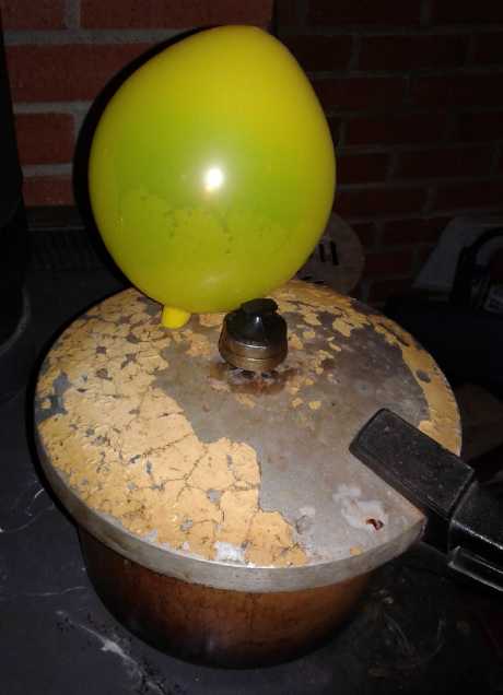 "Exploring Stirling Engine for the
woodstove" concepts.
"Exploring Stirling Engine for the
woodstove" concepts.
When the lid is tightened on the pressure cooker pot on the woodstove,
the formerly cool open air (+ water/steam) inside expands with the heat
and partly
fills the balloon, which in the engine would become the stroke of a
power
piston.
I started drawing one up, but it rapidly metamorphosed
into a simpler engine
especially for the woodstove (or of course any "stove burner" heat
source): a
"closed cycle steam engine". My target is 100 watts
continuous electricity from a moderate fire, and I collected parts to
build it.
I did some work on one hard part: the flywheel/magnet
rotor and its mountings. It sits above the pot to connect the piston
rod to.
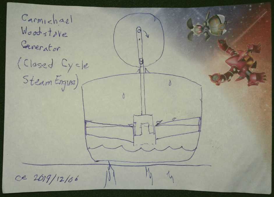 If ever an invention was "drawn on a napkin
over coffee", this was it.
If ever an invention was "drawn on a napkin
over coffee", this was it.
But this simple concept drawing was the culmination
much thought over some days of
rapid design evolution.
Weather and Power and Running the Well Pump on an Inverter
Winds off the ocean had warmed it back up to +7°C. On
the morning of the 11th it was blowing very strongly. The mostly idle
windplant came to life and started delivering record power, around 100
watts, with much fluctuation. (I think I saw over 170 at just one
point.) And my gold plating solution arrived. I decided that was what
to do that day. Then the power went out. Why had I not expected that
some tree would blow down across the power lines? Of course one doesn't
know how long a power outage will last.
Last December it was out for 25 hours after a windstorm -
I think three trees in different places had broken the lines. (I found
2 of the stumps when I drove into town a day or two later. That should
be, um, TE News #127.) Toward the end of that I had plugged in an
inverter and ran my fridge and then the freezer, which were getting
pretty un-cold. Since then - and partly because of it - I had got
serious and hooked up the solar system and more panels than my original
four - eventually 8 more.
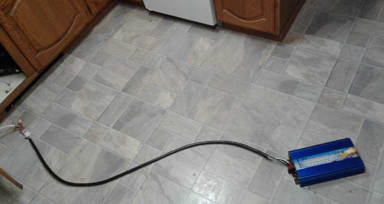
2500
watt inverter plugged into kitchen 36 volt water heater's power socket
in
order to run fridge & freezer
(both here unplugged as the power had come back on.)
 Since there was almost no solar power to the DC system in
the winter overcast (and of course none to the dead power grid), the
heretofore seemingly useless windplant was just what was needed. This
time I just plugged the inverter in to the 36 volts in the kitchen by
unplugging the water heater under the sink. It was making enough power
to keep one or the other, fridge or freezer, running much of the time
without too much drawing down batteries.
Since there was almost no solar power to the DC system in
the winter overcast (and of course none to the dead power grid), the
heretofore seemingly useless windplant was just what was needed. This
time I just plugged the inverter in to the 36 volts in the kitchen by
unplugging the water heater under the sink. It was making enough power
to keep one or the other, fridge or freezer, running much of the time
without too much drawing down batteries.
Since I ran it through the DC
solar (& wind) equipment and its meter, I discovered that the new
2500W and the older 1800W "pure sine wave" power inverters themselves
used
30 and 55 watts, eg, 150W was being used but just 120 was going to the
freezer. No wonder inverters kill batteries if you forget to turn them
off! But they let me run the fridge and freezer enough in case the
power failure became long.
And then, what project for
the afternoon instead of gold
electroplating with no power? I had purchased a 2500W, 230V inverter
(...looks identical to the 120 V one above!) so
I
could run my well pump if the power was off, and a 230V AC plug and
socket. But I hadn't done the wiring. The pump was hard wired to the
breaker box. So I shut off the (dead anyway) power to the whole shop
and garage sub panel and rewired the pump. Now it can be easily
unplugged from the mains and plugged into the inverter.
Then somehow I didn't have the courage to test it. The
power came back at 6:30 PM after just 5-1/4 hours and the pressure tank
still hadn't dropped to where the pump would come on. (I was
conserving.) I could have run a garden
hose until the pump came on but I didn't.
I plugged the pump back into the
mains. Then I ran enough water to get it to come on to verify
that I hadn't made a mistake wiring the plug or socket. But I really
ought to test it on the inverter!
(I also baked an applesauce cake while the power was off
on top of the woodstove by arranging firebricks for an "oven" and
putting the small pan inside. It took over twice as long, well over an
hour. It wasn't well done, but the bottom had a crust. I wished I
hadn't given my old, even
smaller pan to the thrift shop, because it was hard fitting the new
smallest one
into the bricks. (It sat for many many years unused, and I gave it away
a month ago. OTOH it was just one of many items cluttering the
cupboards, and I wouldn't want the rest back.)
The 12th was calm again.
On the 16th I decided it was stupid not to test the well
pump on the inverter when it wasn't needed, instead of during some
power failure when it was. It worked, but it sure was a heavy load. It
drew the Sprint car batteries down as low as 36.3 volts from about 40,
and the drop fluctuated. When it was lowest I could hear the sound of
the flow change a bit, so the 230 volts from the inverter must have
dropped a bit too. It kept running, but no doubt it was pushing the
limits.
Let's see... The well pump has to draw the water up about
66 feet. That's 30 PSI. I had neglected to measure the DC current, but
I didn't want to repeat everything. So later I measured the pump's AC
current with two
amp probes by opening the breaker panel. They said 5.7 and 5.4 amps -
not as bad as I had feared. If the pump drew 5.7 amps at 240 volts,
that would be 1368 watts (almost 2 horsepower), and 38 amps at 36
volts. With what the inverter drew for itself, it would probably be a
little over 40 amps. I'm glad it wasn't higher, and I would probably
restrict my water use to essentials during a power failure. I wouldn't
for example grab a shower in the first hours while there's still hot
water in the tank. I'm not confident this pump power offers complete,
satisfactory service. Of course one must remember it takes a lot of
power to pump water up over 60 feet. I keep a couple of 200 liter
barrels of rain water around just in case, too.
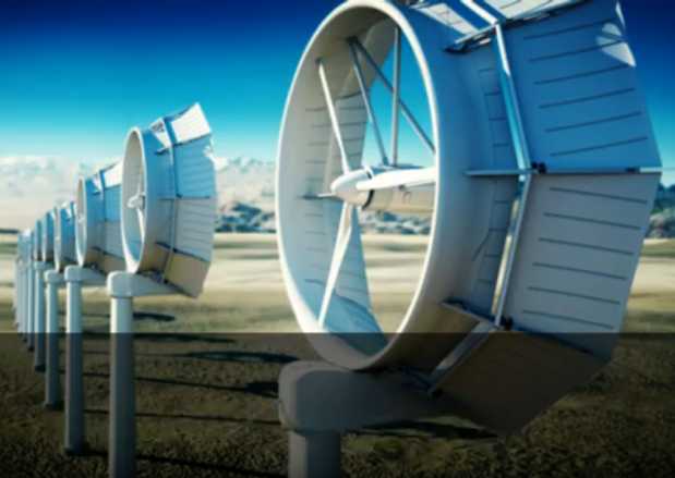
Before departing the "windplant" subject, here are some
windplant flared exit
ducts that might be easier to make than the one with more compound
curves shown
last month. (Youtube) Like them, these probably put out at least twice
the power of an unducted propeller. I still can't help but think that
adding a flared entrance as well to create a full venturi effect would
be even better.
(On the 4th of January at 11 PM, just as I was thinking if I stayed up
late enough I might get this newsletter out, the power went out again
while I was typing. It was only off for 1/2 an hour, but it reminded
that I still hadn't got the solar charging to the Sprint car's lithium
batteries done, which I had started in November but stalled out on in
December to make HAT plugs and sockets instead.)
Power Co. Troubles
On the 13th I heard BC Hydro was having equipment trouble
around
here. Surprisingly in the high wind, the power failure wasn't a tree
across
the lines. Evidently all the diesel generators in the Sandspit power
station are at or beyond service life or time for maintenance shutdown,
but
apparently it was some insulator or something that failed. What
happened to the hydro plant? What a spur to get a
woodstove powered electrical generator working!
On the 16th there was a Hydro crew working on the pole in
front of my house. (They were actually putting a transceiver for the
nearby smart meters on the next pole over. Out here in the country it's
too far between meters for them to talk to each other direct. I wonder
what will happen now about my 'stealth' solar tie-in?) When they were
finished I talked to one named Rob. He had noticed my windplant and I
told him about my wind and solar, the woodstove steam engine and the
idea for a floating tidal power project. I asked about the diesel
generators. The reason maintenance is behind is because the main power
transformer from the small river hydro plant blew last summer and it
hasn't been replaced yet, so the plant has been running on the
'auxillary' diesel generators ever since. (The new transformer has
arrived at and is being tested in Vancouver.) I've seen a few big ones
blow with a blue arcing glow on youtube and it was mentioned how the
power grid could be down for a long time if more than one or two blew
at once because they take so long to replace.
Evidently also, the load on our little grid is much
greater since since everyone in Skidegate Village (technically a Haida
Indian reserve) got heat pumps a year or two ago - and mostly threw out
their woodstoves. (Your federal tax dollars at work.)
Ground Effect Craft/Vehicle (RC Model)
I had been trying to get around to more battery work and
experiments (not very successfully - waiting for supplies) and had been
working on the torque
converter, the new woodstove electricity generator, and the ground
effect craft. Sometime on the 13th it occurred to me that if I did get
funding, I might be doing little but batteries, ad nauseum, for quite
some
time. And working on too many projects meant little steps with nothing
getting finished. I decided to try and get the ground effect craft
model into shape before Christmas. or at least in January. So from that
evening I did some thing or other on it most every day - mostly gluing
and painting fabric. It was very near Christmas when I painted the
second side of the vertical fin and the cloth sagged and became loose
and baggy. (Evidently I hadn't "primed" that side with polycrylic.) It
would have to be stripped off and redone. That meant I wouldn't get it
flying before Christmas and it would be January.
I figured out that each of the powerful ducted fans would
need its own set of batteries - better, two sets each - and set about
mounting small lithium cells as "flashlight tube" batteries in oversize
ABS plumbing pipes. From the specs it appeared they were strong enough
to lift the craft straight up like a rocket if I applied full power.
New Chemie Batteries
 I
received the gold plating solution I had ordered and
plated a copper current collector sheet with a thin layer. If it works
(as I hope and seems likely) it will make for much lower internal cell
resistance than a graphite sheet. The pure zinc to make a new cell
arrived just before Christmas, too late to start anything.
I
received the gold plating solution I had ordered and
plated a copper current collector sheet with a thin layer. If it works
(as I hope and seems likely) it will make for much lower internal cell
resistance than a graphite sheet. The pure zinc to make a new cell
arrived just before Christmas, too late to start anything.
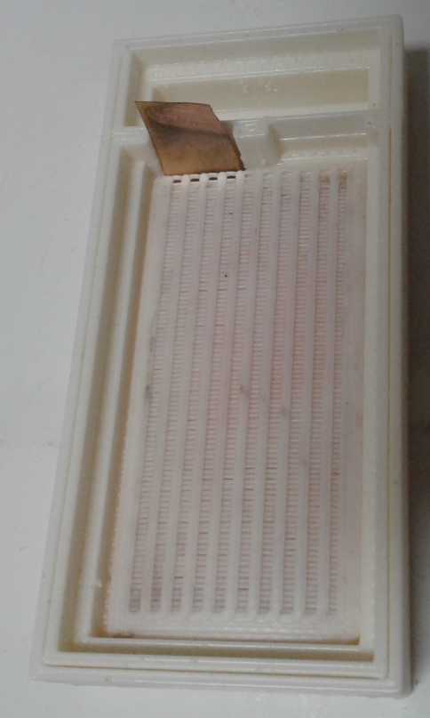
Before doing a current collector I printed the new "lay
down" battery case I've been intending. It has a electrolyte reservoir
on one end instead of on top. Whether or not it's a final configuration
for production,
it'll make experimenting easier because I won't have to glue the front
- now top - cover on to keep it from leaking. That of course makes
disassembly for inspection and electrode replacement much easier.
On the 20th an e-mail said
the application to the "Charge
the Future Battery Challenge" for funding to finish the research and
then hopefully get the batteries into production had been rejected.
They were awarding funding for up to five projects. I had only asked
for
1/2 the maximum amount. I was planning to use that to not just create a
prototype but to get to initial battery production. What was it about
this that it wasn't their dream project? Of course I won't abandon it
since I think the batteries will prove to be both better and cheaper
than lithiums,
but it is certainly disappointing to get no help for getting to
production stage.
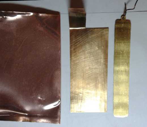 Plain copper, gold plated copper, pure gold
anode for electroplating.
Plain copper, gold plated copper, pure gold
anode for electroplating.
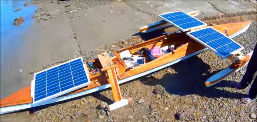
A Solar Kayak
It doesn't have to be complicated... Here is an
interesting kayak that is powered by the sun, which runs the white
motor and propeller on the side. No batteries. In the video the power
would cut out whenever he went under the shadow of a bridge, and he
would coast through. (I was guessing he was on the Danube river but I
don't remember why and I've misplaced the URL.)
In Passing
(Miscellaneous topics, editorial comments & opinionated rants)
Hair
Loss:
the
Demodex Mites
I came across a word, "alopecia". On Wikipedia it redirected to "hair
loss". There is a considerable article. But I think Wikipedia and many
others err in the belief that little can be done about it - and about
its prime cause.
One point which wasn't stressed but that grabbed
my
full attention, is that an almost microscopic mite is 'sometimes'
involved. I had
so
strongly suspected some mite as the prime cause of hair loss as to be
virtually sure of it. But until now,
I've never seen any mention of one anywhere. So I had thought, well,
surely it would be known if there was one... Maybe it was an unknown
bacteria then? But that didn't seem to fit the observations.
But such a mite is known (apparently not by very
many people!) and
it is called Demodex folliculorum. Apparently many or
most people
have it on their skin. It lives only on human skin. It multiplies in
the hair follicles 'especially on an oily scalp' and its food includes
essential hair nutrients (sebum) secreted in the follicles. (One
expects the scalp is the oiliest skin, with extra from infrequent
shampooing, or maybe a poor shampoo.) I would
say they must also live quite well on a perennially cold scalp.
Related
Demodex species cause "mange" - loss of fur in dogs and cats with
weak immune systems. Perhaps one might ask: Why would they not
be the cause of human hair loss? Perhaps our hair thins as we get older
because
parts of our immune systems weaken? Where would it be weakest? Where
the blood flow is least, in top-of-scalp blood vessels, especially when
vaso-contracted and with the pores closed off
in cool to cold air? I suspect this mite plays a far larger role in
hair loss than is apparently suspected, either by its immediate or its
long term effects or both. In fact I think it is central to
the whole topic - the primary cause of hair loss.
On January 5th I did another web search and discovered
that there is another species: demodex brevis is half the size,
(about .15 to .2mm long) and also feeds off sebum. It is the mite that
inhabits eyelashes, but it can be found anywhere on the body including
the head and may cause scaly skin and other skin conditions. Demodex
mites are more common in men than in women... and which sex is it that
often becomes bald?
How is it these mites are never mentioned, even in
writings and studies
about hair loss? The Wikipedia article was the only place I'd seen it
mentioned until my web search, and the couple of articles I looked at
about Demodex weren't about hair loss but skin conditions.
Surely all this should be common knowledge... but evidently it isn't!
At least the mites seem to have never been taken seriously as related
to hair loss.
The existence of mites explains the likely reasons the
several methods I've unearthed for helping to keep hair work: they
eliminate or reduce populations of these critters to harmless levels
or keep them from multiplying and thriving - much as I was suspecting
but had no real evidence for.
I now
wet my scalp with ethyl alcohol just before a shower, once a month.
(Over Christmas I discovered once a week should be much better. The
shower is because once it has killed the mites it seems to have no
further purpose
for being on one's scalp and I would rather wash it off, after having
apparently got shingles from it by the daily use experiment without
washing it off, a few months ago after 3 or 4 (?) weeks.)
And the reason letting shampoo sit on the scalp for a
couple of minutes is helpful would also be so that it penetrates the
pores and hair follicles where the mites are living.
In fact it would seem that all the things I
mentioned in
TE News #137 (updated list below) are helpful, and that the things that
are helpful to keeping or regrowing hair are things that eliminate
mites or make it harder for them to thrive and multiply.
For me the extra pillow to keep the top of the head
warm at night (or a nightcap, as well as a tuque or hat in the daytime
in winter) seemed to be the last missing piece, as my hair seems to be
getting noticeably thicker again in the areas where it had become so
thin.
Unfortunately as ideas and treatments regarding this topic
gradually came to me, I
didn't have the thought to take any "before" pictures months ago or any
previous time, so once again it's just an impression that is hard to
verify. (I've taken a couple of pictures now. I was going to wait
another month or two before revisiting
this topic to be quite certain it's thicker if not back to
full thickness, but learning about the nearly microscopic (.3mm long,
thin) mite I thought surely must exist, has prompted me to write.)
The mite is doubtless easily spread by contact. For
example, someone with it
rests their head against the back of a sofa, or on a cushion. Another
person occupies the same seat or uses the same cushion... Small wonder
"most" people have them!
During my Christmas holiday I had other things to do than
think
about it. I took a comb and no brush. I also had no shampoo except in
one shower. There were no light, formable pillows to pull over my head.
By the time I was returning home, I could scratch little
bumps off my scalp, which are surely an indication of 'robust' mite
activity and conditions for hair loss. (Shall I call them "scabbies"? -
flakes like little scabs. It seems the mites prefer closing off a door
between them and the outside.)
The very few days it took them to multiply and become so
active suggests a more frequent ethyl alcohol treatment is desirable. I
think I'll go for once a week just before a shower, instead of once a
month. From my own experience one wouldn't want to do it much more
often than that, and I'll wash it off soon after.
Helpful Methods for Keeping (& Restoring?) Hair
- tuques, beanies, caps and hats for keeping the head warm and the
pores and follicles open in cool and cold temperatures. (indoor and out)
- lightweight, "shapeable" extra pillow 'overhead' or a nightcap,
likewise for keeping the head warm, in cool to cold bedrooms.
- frequent shampooing/showers, leaving shampoo on the scalp for a
couple of minutes or more to soak into the hair follicles where the
mites are living. (Some shampoos are evidently considerably better than
others. It would seem there's a reason the most popular brands are
popular.)
- at least a daily hair brushing for more scalp stimulation than using
a comb. Some brushes offer much more stimulation than others. It seems
to get the blood flowing more, which would boost the effect of the
immune system on the scalp.
- weekly spraying or rubbing of ethyl alcohol on the scalp to wet it
all over and kill the mites, before a shower. Ethyl rubbing alcohol and
vodka have both been used. Once applied for (?) a couple of minutes it
is desirable to wash (shower) it off.
- I understand cutting the hair very short or shaving it off is
helpful. I'm not sure why. Perhaps the mites have nothing to cling to
or climb on as they try and spread from follicle to follicle?
I suspect that these methods just might bring back hair to
a bald person or at least one with very thin hair, perhaps only
eventually, but that's not a promise.
Here's a perhaps humorous aside: When I was first
suffering from itchy scalp and the probable beginnings of hair loss in
about 2004, I knew little about it and I went to the clinic to see a
doctor. The doctor that saw me was bald! This seemed ironic. All I
could think was that whatever advise he gave me, I should do the
opposite. After that I began looking for my own information.
DISCLAIMER: I
am not a medical professional.
Any use made of this information is by your own judgment and at your
own risk.
Social
and
Political
Evolution
Just as scientific and technical progress comes about
through experimentation with new ideas and concepts, so does social
evolution. Somehow while we experiment freely with physical sciences
and technologies, we have been conditioned to be exceedingly timid with
social experimentation. To an extent this is probably good, but if we
are so blind as to attribute longstanding and developing social
structural problems to individuals and think things will go 'back to
normal' once they are gone and someone else is in charge, if we are so
timid as to refuse to face facts
and experiment when
changes are clearly needed, if we too much fear any slight possibility
of making things worse, we end up with an unprogressive "status quo"
whereby the few rich and influential increasingly have hijacked our
democratic social processes and have been converting them into a shell,
a
facade of democracy that they control for their own benefit behind the
scenes.
It has become almost impossible to win an election in
western nations without
being beholden to these special interests. Vast numbers of people,
especially older people, don't understand that there has been an
ongoing shift away from meaningful democracy and toward it being merely
a façade for hidden totalitarianism - so far by an
oligopoly rather than a single dictator. But many - especially those
specifically wronged - are coming to recognize that the government at
present is
no longer their friend but their enemy. "I'm from the government, I'm
here to help." is a phrase that strikes terror into many hearts rather
than assurance.
I say social experiments can only very temporarily
make things worse, because once people start to recognize that the
worst problem of all is fear of changing
existing systems and institutions, they become unafraid of social
experimentation and there evolves a culture of social experimentation
(and not only political but in family, education, economics, health -
all
social areas and institutions), whole
new arrays of possibilities will open up from each experiment. The
better
models will be chosen and the poorer ones will be dropped. Even
failures may illuminate the way toward a bright future - if they don't
become "the new normal" that is too sacred to change like so many
long-ago-failed experiments or utterly outdated techniques and
procedures in
use today.
For a parallel, the whole vast internet with
all its intricacies has opened up in just around 30 years because of
people with vision and ideas, and some pretty wild experimentation.
Things that
didn't work well have dropped away, and things that did have opened up
more and more realms for exploration. Even the failures, the "wastes of
money" and the "dot com bubble" have paid back a millionfold in
progress. The changes we've seen and have
so quickly taken for granted weren't even imagined in science fiction
when I was young.
It has been stated that if one asked an audience to list
50 technical advances in the last 50 years, most could come up with a
fair list. If one asked the same people to list 5 social advances in
the last 500 years, few would complete the task.
Why are we terrified to experiment socially? Why do we
stick with
what used to work 100 or 200 years ago in preference to trying anything
new? - just in case it might not work out? But what worked
for a while back then isn't working any more.
The most damaging and dangerous thing to democracy and the
continuing evolution of
peaceful civilization is unwillingness or inability to change when
society and the
whole world
is continually changing. If a democracy has finally become disrupted
and bankrupt, if violence and riots instead of peaceful and working
processes become the
only effective method of voicing distress and getting change, there is
a reversion to
dictatorship where there is no active social participation by the
public, and it may be 50, 100, 150 years before democracy is able to
emerge
again.
We must act to evolve our social mechanisms in all areas,
progress instead of reverting. While social experiments should be
cautious to a point, we should not be starved of them just because not
all of them will prove to be the ultimate in nutrition.
"Those who make peaceful revolution impossible will make violent
revolution inevitable." - John F. Kennedy
"Riots are the voice of the unheard." - Martin Luther King Jr.
Here is a very pertinent present political example to take this from
the abstract to the
concrete. I have no doubt many readers will take strong exception to my
view of the situations, but they are as I see them and I know many
others hold similar views:
Virtually the whole social decision making body in the
USA, which
includes (at least) the strongly intermingled members of the upper
civil service, the justice system, the largest corporations, and the
propagandizing oligopoly (virtually monopoly) major news media, had
become
almost completely corrupt - self serving, for sale to the highest
bidder, and filling all the posts with more like themselves. Political
party
matters not. With their own corrupt people heading the justice
system, they have felt - and have been - more and more safe to do
whatever they please without fear of prosecution. They have pillaged
the society they supposedly work for until most of the population is in
overwhelming debt and 50% of Americans say in surveys that they
couldn't come up with 500 $ in an emergency.
Those in all the high places universally
detest and fear the new
president because he won in spite of all their machinations and
whatever else he is doing, he is
indeed attempting to 'drain their swamp' as he would put it. Before
that they had everything their own way. Those behind the scenes bought
the elected
'leaders'. The public was 'free' to pick anyone, but from a slate of
the gangster "elite's" behind the scenes choosing - Tweedledum or
Tweedledee. No one got
into high
government or corporate offices without first proving they were corrupt
and would play along.
A great many people realized that government had become
their enemy instead of their friend, but there was no avenue of
expression for it until someone - anyone - from outside that "club" was
able to run for the presidency and have a serious chance of
winning. It seems incredible how bad it has become. Laws were passed to
protect the 'cleptocracy' from the public instead of the other way
around, not excluding permanent
suspension of the centuries old and hard-won rights of Habeus Corpus
(innocent until proven guilty) and the right to a fair and speedy
trial. No such safeguards for "terrorists!" -- to be defined as
expedient. Forget the fair trial: Take a plea bargain sentence or we'll
throw the
book at you. Many people, often America's real elite of creative
problem solvers and thinkers, have been thrown in
prison without trial, died
"accidentally", been murdered or "suicided" with no investigation over
the last two decades. How many political and social prisoners does the
USA now hold?
Their chosen figurehead for 2016, Clinton, early and
clearly indicated her willingness to take orders from them rather than
to exercise leadership against their wishes if she won the election.
Her astonishing statement to that effect to the Council of Foreign
Relations (the "CFR", perhaps the heart
of the "club"?), "I'm so glad we have you to tell us what to do!" (I'm
not sure those were her exact words. There was a smile on her face.),
from
the lady who wanted to "lead" the nation, made it onto Youtube. They
have done their utmost to prevent democracy from working against
themselves, or for the people, not short of illegal acts (to brag
about at the CFR) and a continuing barrage of unsubstantiated
allegations and a false narrative - not excluding
outright lies - on television and in print, repeated over and over a la
Goebbels/Hitler, which unfortunately are swallowed by so many with no
inkling that they might not be true or that the media is biased.
Perhaps most famously "Saddam has
weapons of
mass destruction.", repeated over and over and over on the news, was
used to justify invading Iraq. None were found.
Well, let's blow some other minor story(s) out of proportion for a week
or
two that will make the public indignant and distract attention from
that.
Or how about:
Media: 'Worthless Trump is playing golf over Christmas [2018] and
ignoring the many things that need to be done.'
Actual: Trump was in Iraq visiting the troops, and trying to figure
out how to extract them from Syria.
To be fair Trump doubtless didn't tell anybody where he
was going until he was there, and the white house may have even put out
misleading hints. Saying he was traveling to the Middle East would
have invited planning for an attack on himself.
(It was Obama who was always off playing golf. That wasn't
a criticism then as "Mr. Teleprompter Reader" was pretty much doing
whatever they wanted. ...But I do credit him with calling off the
imminent US invasion of Syria in October 2013 after George Galloway in
parliament caused Britain to back out of the operation against prime
minister Cameron's plans and wishes, and Syrian
leader Assad offered to dispose of all Syrian chemical weapons under
international supervision. What a relief that was! It then degenerated
into a poorly coordinated proxy war
supported by USA and Soggy Arabia. At one point Pentagon backed rebels
and CIA backed rebels were even fighting each other. ...Hmm...
notice
all the US drone strikes seem to have stopped since 2016?)
 Frequent floods covering
seemingly vast areas
are why I now call it "Soggy Arabia".
Frequent floods covering
seemingly vast areas
are why I now call it "Soggy Arabia".
Here is yet another bunch of camels up to their necks with someone
trying to lead them to higher ground.
(Nared King Youtube videos show the various unprecedented cataclysms
happening all over the
world.) But I digress.
Social media telling a wholly different story than the
"sanctioned narrative" - with prompt reporting on attempts to rig
ballot
boxes - probably turned the tide in 2016. And polarized the nation and
other
nations - and even families - as never before, because the two "visions
of reality" (as my grade 9 English teacher in California would put it)
were so different
and so utterly opposed.
Since 2016 some of the worst of the corrupt have
resigned, 'not run for re-election', retired or been fired, and some of
the many pedophiles in high places are being weeded out. A great many
in high places know the many crimes they have committed, never
expecting to be called to account in their mortal lifetimes, and are
now in fact terrified of
being sent to prison. That's why they they fought so hard against an
honest judge being appointed to the supreme court.
(H. Clinton saying "If that
___ing Trump wins, we'll all hang!" ...was that a clean conscience
speaking?) Whatever one thinks of Trump as a person, his almost
miraculous election - and the fact that he
has so far avoided being murdered or deposed - in fact gives hope that
democracy may be salvaged. But what happens when the
billionaire they can't control is gone, and the corrupt go back to work
to restore their hidden influences and "refill the swamp"?
They have done nothing but demonize, fight and obstruct
everthing the president tries to do, and to try to find - or falsely
create - any grounds for having him dismissed. Agendas given strong
approval in lip service but no action in the past (like a Mexico border
wall) are suddely "pure evil" when the new white house tries to
actually implement them. (After all, it interferes with their highly
profitable drug running and human smuggling.) Having failed for almost
four years, they now presume to impeach the president on (groan)
"Trumped Up"
allegations amounting to nothing.
(The corrupt who may well have had Bobby Kennedy shot, and
got
Nixon elected, behaved similarly when
he turned about-face and ended their "profitable" Vietnam war,
diplomatically recognized China, and started nuclear arms limitation
talks with the Soviet Union. Until then he was immune. Anyone trying to
expose him would have been silenced. After he "double crossed" them by
doing things for the nation and the world instead of for them, the
dirty laundry was
brought out and he was forced to resign.)
How can things be "brought back to normal" without the
house burning down besides by making social advances toward a new and
improved "normal" - a society which will ever be adaptable - flexible
and able to change with human progress, and in which concerned citizens
- or 'social sustainability design teams' of concerned citizens - have
a say in the operation of the government instead of just a vote
every few years for someone whom they then have no control over?
Small
Thots
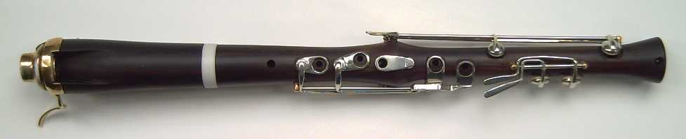
* I'm sorry no virtuoso player was ever
able to take up the "Supercorder" instrument I created and made over 20
of between September 2003 and sometime in 2006. In order that a fine
instrument with such a gorgeous sound may not be forgotten (and perhaps
may even be produced by someone?) I (at long last) made a video of me
playing
Vivaldi's Recorder Concerto in A minor RV445, and put it on Youtube.
I was never a virtuoso player and not in my prime either, but perhaps
the qualities
of the instrument itself may be heard here and there in the playing.
https://youtu.be/MErSlx1luuQ
(Yes "youtu.be" is a valid Youtube URL.)
* When I saw a "5GHz" light on my fiber optic router I naively
assumed
that was the same as "5G" cellphone system - and that that must be why
it was called 5G. Sorry, my mistake. Apparently they are completely
different entities.
I do however still maintain that microwaves go
though people rather than around them and that you're better off if
they don't, and the more powerful and the closer they are, the worse it
is. There is various evidence for and stories about this even tho no
proper long term studies have ever been conducted. Sumsung brand
cellphones have one of the lowest radiations, but I usually put it on
"louder" and hold it away from my head when I'm talking.
...I also still don't understand why the new cellphone
system is called "5G" instead of "G5".
* What kept me from designing the flat battery cases and new HAT
plug and socket shells? ...The "notebook" computer I use and 3D printer
were in about the coldest little alcove of the house. I didn't just
move
it because it was attached to a big video monitor for doing the
graphical work, and it was next to the 3D printer. Being winter the
situation could persist for months.
Say... how about setting a small electric radiant heater there just for
when I want
to work? Duh!
* USA nuclear reactors produce about 2200 tons of radioactive waste per
year, with an accumulated total of 88,000 tons so far. One of the waste
byproducts, plutonium, needs to be stored for 30,100 years. (or is that
just the half life when it becomes only 1/2 as radioactive?) Nobody
wants it stored in their state, even in a hollowed out mountain. (in
which some tunnels have already collapsed.) In 30,100 years of nuclear
power, 66,220,000
tons of spent fuel would need to be stored. Then in the year 32040
(maybe) the first fuel from the 1940s can be released from storage.
Yup, nuclear power is a great, sustainable solution! New solar plants
are much cheaper to build and to operate. It seems to me that for
anyone to propose a new nuclear power plant today betrays either
willful
ignorance or vested personal financial interest or both. Fusion or
thorium reactors too would create radioactive waste - perhaps less of
it, perhaps shorter lived, but that would just be reducing a still
seemingly unsolvable problem.
* Every generation since world war two has been poorer than the one
before it. This is in large part due to dilution of resources -
their being
spread between more and more people, including with older generations
that "already have", on average living and retaining their resources
longer.
Adults under 40 in North America today command only about
3% of the GNP instead of 25 or 30%. The generalization is that they are
still living
in their parents' basements. They mostly have low paying jobs while
everything needed to live (especially housing) costs more and more.
They can't afford homes and a large percentage don't have and will
never have their own families. (Of course the gap has not gone
unnoticed. This article speaks of organizations trying connect old and
young people together for mutual benefit: https://getpocket.com/explore/item/the-real-trick-to-staying-young-forever?utm_source=pocket-newtab
[hmm... had to type that in - hope it's right])
They have developed a disdain for the societies that
nurtured them in youth but provide them so little for life in
adulthood. Most of
them have no idea of the societal collapse that is soon to happen, but
those who do say "Yay, it's all going to end!" (As an accomplished
inventor
with so much to offer who has been repeatedly spurned and has got so
little from - and been able to contribute so little to - our society, I
have over the decades come to share their disdain. Apparently I am now
much more valuable to our government for having reached the magic age
of 65 on January 1st 2020 than for a lifetime of inventing new or
improved things to try to improve the world, and I will finally get
some funding: old age pension. It'll be more money, and how each penny
is spent won't even be scrutinized, audited and disallowed! How much
longer currency will be worth anything is another question.)
But
soon the younger people will be inheriting everything as older
generations die off,
and will occupy the seats of power and influence. Then as they don't
have the same values and ideals as their parents, rapid social change
is not only possible but inevitable. The various calamities we are
starting to face will propel this change.
If change is channeled in positive directions, social
evolution may take a great leap toward sustainability.
* Notwithstanding all the global crop failures, South America's crops
did well. China bought corn from Brazil this fall. USA also bought corn
from Brazil. Now a Brazilian company has bought corn form Argentina
because Brazilian corn has become too expensive. Now Argentina is
putting very large tariffs on corn and other grains for export,
probably fearing there soon won't be enough for Argentinians. China
will probably just pay the tariffs.
Unlike in past times, crop failures in some countries have
become everybody's problem worldwide and if the 2019 and 2020 forecast
crops continue to fail, hunger threatens to be global. Some have noted
on youtube hints that governments are planning for potentially
rationing food.
ESD
(Eccentric Silliness Department)
* Which salad has the darkest
color?
- Coalslaw
(Okay, I admit that's pretty juvenile!)
* Apparently it wasn't "cake" that Marie Antoinette commended to the
peasants. It was "brioche"(SP?), a favored bread of the French upper
classes.
Squire: "Majesty, the peasants have no bread!"
Marie: "Then let them eat brioche!"
Squire: "Majesty, have you lost your head?"
* A Title for the accelerating collapse of glaciers and rapid melting
of the ice: "Antarctica, the Incontinent Continent"
"in depth reports" for
each project are below. I hope they may be useful to anyone who wants
to get into a similar project, to glean ideas for how something
might be done, as well as things that might have been tried, or just
thought
of and not tried... and even of how not to do something - why
it didn't
work or proved impractical. Sometimes they set out inventive thoughts
almost as they occur - and are the actual organization and elaboration
in writing of those thoughts. They are thus partly a diary and are not
extensively proof-read for literary perfection, consistency and
completeness before
publication. I hope they add to the body of wisdom for other
researchers and developers to help them find more productive paths and
avoid potential pitfalls and dead ends.
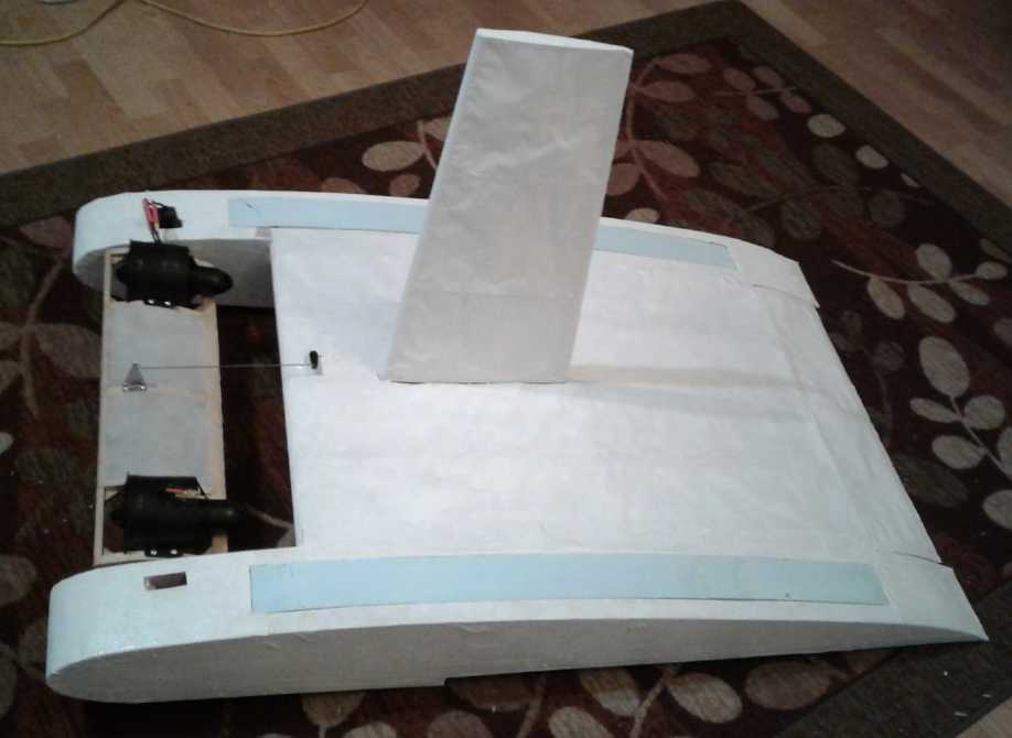
Ground Effect Vehicle (...first the 1/4 scale R/C Model)
State of the model before
Christmas
It occurs to me that at
least one of the RC catamaran models on Youtube could fly up way above
the ground. Its
motor seemed perhaps strong enough to almost lift the lightweight craft
straight up, and it flew at a high angle of attack, the propeller
almost dragging along the body as a dead weight. And the Wises craft
had gone a ways above the water. It's possible the two ducted fans,
each rated at over 3 Kg of thrust, might likewise be able to pull this
craft up out of ground effect and higher up (if not straight up like a
rocket). If so, it should have
ailerons to prevent tipping over sideways! (Split the canard in half as
two independent airfoil
surfaces? - yikes!)
Flying up high is not a design aim, but it might have
value
for
avoiding, say, a whale that suddenly jumped up in the path, or a
deadhead bobbing up from the waves. Or to fly over ice or a protruding
sand bar. Or even a boat or ship. But it would require substantially
more skill to drive it... Hmm.
Another thing that occurs to me is there are all these
radio controlled(?) drones with GPSes that can be programmed for
various things like to fly a specific path, maintain an altitude,
return to their starting point and land, and so on. I'm not much into
trying to duplicate that sort of programming, but somebody might be.
Then even the model could be programmed to deliver something somewhere
or to take video along a route.
(15th) Controlling the two ducted fan motors remotely in order to steer
seemed to pose a considerable extra problem because the radio control
wasn't set up for it and its options were so limited, but I have
thought to use the "ailerons"(?) control, sideways on the same stick as
the motor control, and take out the springs that return it to center.
OFF would be bottom right, FULL power would be top left.
If I found when I removed the cover that I could somehow
twist the whole control 45 degrees so "up" was full and left and right
varied each motor to turn the craft, so much the better.
In connection with this whole thought, perhaps I should
look on line for a different handheld remote control transmitter? Just
because I bought this one am I stuck with it? Maybe there's one already
made with the "two throttles" configuration I need? Nope - they all
seem to have the same left-right-hand, two-simple-joysticks
arrangement. If the canard was computer controlled I could use the left
and the right joystick as 'throttles'. But for the first model it's not
and I don't fancy having the canard be a sideways motion on the same
stick as a throttle.
On January 4th I opened up the controller/transmitter and
took the spring out. Trying it then, it didn't seem it should be too
hard to control.
Canard & Ducted Fans Mounted on Canard
(8th) Having mounted the ducted
fans I started painting the "Minwax Polycrylic" on the fabric now and
then. For all that the model airplane builders raved about it, it
seemed to be taking a lot of coats. From 75% thinned I went to 67% and
then 50%. And I turned the craft vertical so 'drips' ran along
the
fabric instead of through it. That and more coats seemed to help - it
started to get
harder to blow through it. And I cut and shaped two pieces of styrene
foam for top covers for the hulls.
Nothing fast, but the snail had picked up a little
speed. I'd like to get it done and try flying this thing!
(13th) I decided to concentrate on it. Could I try to fly it before
Christmas? If not, perhaps in early January? Unrealistic? How about
"Sometime in January"? I had already done a
couple more coats of polycrylic "dope" on the fabric.
That evening I did a bit of epoxying on some flakes of
foam to fill in
some low spots on the bottom. Then I could put the fabric on the other
hull.
Then I cut and shaped pieces of wood for the "dorsal fin"
lateral stabilizer. Then I epoxied them together. (14th) I
added some triangle gussets and more epoxy to strengthen it. But I was
still wondering how to attach it securely. I decided to more or less
epoxy it into the wing.
Then I got out the thinned carpenters' glue, spread it
around, and glued the light fabric onto the other hull. The styrene
foam needs at least some protection. I'm bound to fly it
into something or run it across some gravel. It took a long time to do
the whole hull in one go.
(15th) Covered the fin. Later gave it and the wind a coat of polydrylic.
(16th) In spite of the model aircraft builders raving about it, I got
fed up with doing coat after coat of polycrylic - and it was still
transparent and still had the grain of the cloth. I really wanted a
smooth, solid, white finish. I dug out a can of Tremclad oil based
white rust paint that I had got at the recycling center a couple of
years ago. (4L, almost unused and still like new - hardly even needed
stirring! Probably cost somebody 60$.) I filled a large ointment jar
and painted the underside of the rear 'elevator'. It didn't seem to sag
the way the wing fabric had when spray painted, whether because it was
primed with the polycrylic or because it was a different paint, I don't
know. Then, not wanting to wash the brush with paint thinner after such
a small job, I did the bottoms of the hulls. The fabric being glued to
the styrene foam, it couldn't sag.
On the 19th I found out: I painted the second side of the
fin and it stretched and sagged badly. I guess I hadn't 'primed' that
side with polycrylic. But later both sides looked just as baggy. After
that I decided I shouldn't have just bare
fabric anywhere in the full size vehicle. Instead I would put the
fabric over styrene foam, even very thin foam, to keep it flat and
smooth. (Score one for learning by making a model first!)
Wiring
The "ESC" motor controllers seemed to have awfully heavy
power wires - about #8 AWG. I looked at the motor specs again: 112
amps. Okay, they probably needed at least #8 wire. To go across
the wing from the battery to the other motor would need two wires over
3 feet long. I got out a scrap piece of #8-3 electric stove wire
about 4-1/2 feet long. 600 grams. Then I weighed the batteries.
* 40 inches #8 AWG copper wire: ? 200-250 grams.
* 6 of my intended lithium cells: 640 g
Adding a second set of 6 batteries in the other wing would
save having to install the heavy wires, so they would only add an extra
440-390 grams instead of their full weight. And they would double the
potential travel distance. Besides... Oh wait! 100+ amps was an awful
lot to
ask of these little cells. 200+ was much worse. In fact, the motor
sheet recommended larger cells. So I should probably put in, not one
set, but two sets in parallel for each motor - four
sets, 24 individual cells, 2560 grams! That would about double the
entire weight. Without giving it too much thought, I had expected the
batteries, for short test flights, would be pretty trivial. Like my
quadcopter drone. Well, it
won't fly without power. And if the motors really do put out over 3
Kg of thrust each, in theory they should still lift it straight up if
it was launched like a rocket.
Obviously then it should also be easily capable,
power-wise, of flying above ground effect. But if it did, it would need
ailerons. I decided to forget about that for now. If it didn't need
anything like full power at any time to fly in ground effect -- Good!
Low power is supposed to be a big benefit of flying in ground effect.
And I don't want to get into aircraft regulations or
needing
pilot skills to drive the vehicle. OTOH... being able to fly up higher,
even tho using more energy, could be a safety feature if a stormy sea
with very big waves blows up during a trip. It would be fantastic to at
least be able to stay safely above those notorious 4 meter wave crests
on stormy Hecate strait. Or I suppose, on a vessel intended to travel
between open Pacific (Hawaii...) or Atlantic (Canaries...) islands, to
be able to go up as high as necessary whatever the sea. That would be
the ultimate in seaworthiness. And one could, of course, computerize
the elevator and aileron controls to minimize the skill
level required. The driver just tells it the desired height. ...Then of
course there's 'just program the entire travel path via GPS' and the
driver merely watches for obstacles, then taxis it to the wharf and
ties it up. But I'm looking far ahead here.
I took apart the battery pack I was to take the cells
from.
It didn't lend itself to any reconfigurations. The cell voltage was
higher than I'm used to for lithiums, almost 4 volts. But I don't know
the chemistry of these ones. Would they drop to 3.2 as soon as there
was a load? I discovered that 6 in series read 23.05 volts. The motor
said 22.8 max. No doubt as soon as there was a load the voltage would
drop
under 22.8, and maybe under 20. But I didn't want to exceed any specs
at any time. The motor controllers said 22.2. So for now the series
sets would be of 5, which read 19.2 volts. I'm pretty sure there's lots
of excess power. If it won't take off, or if the voltage drops a lot
once they're in use, I'll go to 6 cells.
So how to mount the batteries? I decided putting them in
tubes of 5 (or 6) sounded like the best option. For that I needed to
find (or make) a plastic tube of the right diameter. I didn't have any.
Shopping list... I couldn't find anything different than what I already
had. I decided to use the smallest I had that would hold them: 1.25"
ABS drain pipe. I could put in a bar or two to hold them at one side of
the tube. Or maybe I could heat and stretch a 1.25" PVC "sprinkler
system" tube into an oval shape, and put two sets in each tube?
EV
Transmissions:
Off-the-Shelf
Planetary
Gearbox
for
Miles
Truck
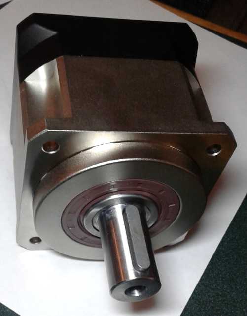
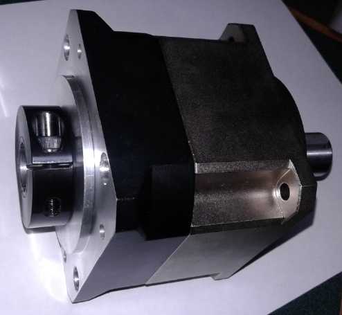 The 5:1 planetary gear. The input is a
socket instead of a shaft.
The 5:1 planetary gear. The input is a
socket instead of a shaft.
It is intended that a motor's shaft insert into the socket and that the
gearbox bolt onto the motor,
but it will be ~18" away from the motor and the socket is too small for
the shaft anyway.
(18th) The 5 to 1 reduction
planetary gear finally arrived. It looks pretty tiny for a vehicle
transmission and the shafts are pretty small, but the torque specs
looked adequate, and then much of most transmissions is the housing.
This was the innards in a small shell. (It was sent by Federal Express,
but I picked it up at the post office. On January 3rd I got a bill for
101$ from FedEx, of which 37$ was tax. The rest was FedEx collect
charges. Total FedEx bill for one small (albeit heavy) item: ~ 125 $.
Distraction!?! The ground effect craft model that I was
focusing on could be done in a month. Could the truck be done in a
week?
It was tempting. Well, I didn't even have a week before Christmas.
Presently the motor is bolted to a bracket which holds it
in place under the vehicle. The front of the transmission bolts to the
motor, and another bracket holds the rear end under the truck, which of
course holds the driveshaft steady.
Now I have to figure out:
a) How to attach the gearbox to the truck where the back end of the
transmission was.
It will need some sort of mounting plate. It needs
to hold up itself and
the driveshaft securely, the body not twisting (in any
direction) with torque or axial forces.
b) How to attach the motor to the gear. It will need to be some sort of
adapter shaft,
with an extension to take the place of the removed
transmission (~18 inches).
c) How to attach the driveshaft to the gear. Doubtless it too will need
to be
some sort of adapter.
But perhaps the first thing to do is to get the truck
running again after the "Delta Q" battery charger boiled at least some
of the cells dry. I hate to look! If I can't get those working again,
even temporarily just to move the vehicle, I'll have to put in 2/3 of
the lithiums from the Sprint. (That's the plan anyway for once it's
running well. Can I make batteries before I just really really need
to buy more?) And then work out a charging setup that won't do what the
charger that came with the truck has done to the batteries that came
with the truck.
At the start of January I looked under the truck in the
cold garage again. I had the thought that it would be much nicer
crawling under it in the summer when it was warm.
Other
"Green"
Electric
Equipment
Projects
Easier HAT Plugs and
Sockets
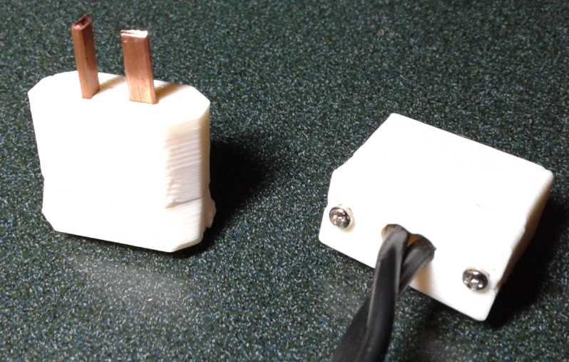
On the night of the 3rd I did up a "simpler"(?) shell to
hold the 36V, 15A HAT plug pins described in the previous issue. Owing
to the fat 1/4" pipe squashing out so far - to at least 9 mm long, they
were rather large. I'd even say "clunky". Very square. I can only hope
the 5 mm or 6 mm pipes allow for smaller shells. I'm even thinking I
should have ordered some 4 mm. One could always squash them down to an
oval to fit over the pin before completing the crimp.
At this size one might almost put screw connections on the
blades. Perhaps I could move the screws to the sides instead of the
ends. The would make it shorter but fatter.
Of course there were teething troubles. Even on "take 2"
The crimps were still hard to fit in - must have squashed out to 10 mm
instead of 9, and the machine screws didn't hold well. (What, specify
even smaller holes? Usually I have to ream them out with a tiny
screwdriver to get the screws in at all.)
(8th)
After
talking
with
Mike
the previous day, we decided the new
shell for the "crimp-on connection" type HAT plugs was nice, but that
rounded corners would make them nicer. I did beveled corners thinking
that would be easier in OpenSCad, and "3D" beveled the back part to
make
the corners
protrude a bit, to make it a little easier to grip to pull the plug
out. I had thought it was awfully bulky, but Mike liked it that way.
There can be more than one type and style. I think a smaller shell for
"solder
on" wire connections would be nice to offer.
I also noted that with the "front-back" two piece shell,
the "crimp connect" sockets could be quite similar to the plugs, with
just a couple of dimension tweaks. I verified this by sticking in a
couple of "Z-fold" blade receptacles (they stuck out the back) and
trying to plug in a plug. It worked, depending on the exact sheet metal
and fold. So, longer shell and slightly wider spaces for the "Z-fold"
pieces. (9th) I designed it and made a socket. (No pic - looks about
like the plug without pins.)
Small Screws
Something I've always been on the lookout for - and never seen anywhere
- is a
source of small "self tapping" screws for plastic. All the local
dealers stop at "#4" screws, and trying to find anything smaller has
been frustrating. If you only want a few you can take apart some old
cassette deck or computer. The hobby shop in Victoria had a few, priced
"each". Sometimes one can find an "eyeglass screw assortment" with a
several, of various sizes. But where were the bags of 100 for actually
making things?
It started to get really frustrating when I started making
CAT plugs and sockets. I ended up using 2mm "machine screws" (tiny pan
head bolts) for them because they were the closest thing I could find.
(And I was doubtless lucky the local electronic parts store even had
those.)
But the fine threads don't hold in plastic very well.
Now I got on line and looked for them. That didn't look
very promising either. And if I order anything from USA they always
insist on shipping any little thing by courier and then there'll be
"brokerage fees" and tax - all for a few stupid little screws? And
still no bags of 100 the same anyway.
Finally I gave up Amazon and e-bay and went to China, to
AilExpress.com .
Sure enough there they were. Several stores, good selection, great
prices, cheap or "free shipping" by mail for small things. I ordered
about 300 from one store in a small assortment of sizes close to what I
think I want: 30$C.
YAY!
I could have ordered just 4$ worth (50 screws), and paid
4$. How can North America compete? Just the obligatory courier shipping
- or even postage for a bubble envelope - is more than that. And then
if you buy enough quantity or "extras" to get up to most
companys' "minimum order" purchase, it's also enough to trigger customs
brokerage fees and taxes, for which the minimum is only 20$, doubling
the
price again. You're up to 40-50$ for one little bag of a few screws.
The Chinese rarely have a minimum order, and they usually write a lower
value on the package so customs won't bother it. And we mostly don't
have the selection - virtually nothing for small screws. Even when we
do, the prices are much higher.
Of course once I had ordered, the system showed me even
better bargains from other stores, that hadn't shown up in my original
search. Maybe next time.
Cura Slicer
Now that I finally have high speed internet I downloaded
Cura (perhaps not the first time?). The file called itself a
".AppImage". That sounded like some sort of archive file, like an Apple
".DiskImage" but there was no suggested application for it and I
couldn't get anything to open it. (I think that's about where I got to
last time.)
Finally I just double clicked on it - again, I think.
After several seconds a small window opened. It was a "ready to run"
application program. That's something I probably missed too: with the
delay when nothing seemed to happen, I didn't wait long enough. Well
[your choice 4 letter word]! Why couldn't they just call it ".app"?
Then one could select print material, printer, and item
to print, and it would "slice" it into layers of print filament in a
G-code file for the printer. There were also "settings". My RepRapPro
usually did .4mm
per layer. Cura defaulted for the AnyCubic I3 Mega (which was on its
list of printers - yay!) to .2mm per layer, optionally .3mm. The
default
print time for a battery cell case was something over 2 hours instead
of 40 minutes - ouch!
I may wish to use some lower rez settings for many items.
After all, the printer printed from the old Skeinforge slicer decently.
And using the low rez print at slightly low
temperature allowed me to print the "porous" separator grilles which
had previously been so elusive.
High Temperature 3D Printing Filaments
While exploring Cura I noted various filaments and their
settings. "PC" was supposed to be good up to 110°C. I thought that
would be a hot enough rating to print electrical sockets from, instead
of going to labor intensive porcelain. With a bit more
exploration starting on the Ultimaker (Cura) website, I found 6/66
nylon (PA, polyamide), which was also high temperature but didn't look
unprintable. (And if "666" is the number of the beast from hades, it
should withstand very high temperatures.)
It claimed detail when printing with this material was
almost as good as with injection molded parts. I ordered some from a
Canadian source because the ones on AliExpress didn't specify what type
of nylon they were and for once they didn't seem much cheaper. (Got it
January 3rd.)
Sufficiently high temperature printable plastic, plus
proper screws, and the metal part designs, should at last
enable commercial production of the redesigned 36 volt HAT plug and
socket items. Next I need to redesign the wall outlet plates and all
the 12 volt CAT plug and socket items.
Essentials For Commercialization:
* CAT plugs and sockets (crimp wires)
* CAT Click-Lock plugs and sockets (crimp wires)
* CAT Wall (triple or more) socket plates (Pigtails or crimp wires)
* CAT Cigarette Lighter adapter socket (CL to CAT only... or both
directions?)
* Same items for HAT 36V. (Lower Priority)
But I would like to come out with a broad range of related
products. It would be best to have at
least some of them on offer at the first launch.
Desirables:
* Wall sockets with built in switches.
* DC to DC Down Converter, in a housing with HAT plug and CAT socket
for running 12 volt items from 36 volts supply.
* Meter box with CAT plugs and sockets to check voltage and current,
and maybe count up watt-hours used.
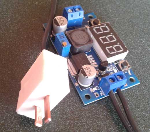
 * Similar
converters that also show the voltages.
* Similar
converters that also show the voltages.
(Unfortunately I have
two such converters out of two that seem to have quit working -
Vout~=Vin. I
either need to find better ones, or figure out why they're blowing.)
One
of them worked for a few days, and it was very nice to be able to read
the state of the batteries from the livingroom, as well as adjust the
12.0 volt
output. I was running a 12 volt LED light with it. A "production" one
needs a 3D printed housing with integrated CAT socket.
 The HAT input plug
* CAT and HAT Programmable voltage and time delay switches (eg, to turn
on
loads when solar or wind is available, and off when it's not.) Ideally
this would have many programmable features and monitor voltage, current
and watt hours consumed.
* 12 volt LED lamps with CAT plugs.
* 36 volt LED lamps with HAT plugs. (the 12 to 72 volt DC LED 'bulbs'
that fit regular E27 sockets, and some regular lamps might be good.)
* CAT and HAT 'electric heater' dump loads. (Probably to be used with
the voltage switches.)
My
Solar
Power
System
Month of December Log of Solar
Power Generated [and grid power consumed]
(All
times are in PST: clock 48 minutes ahead of sun, not PDT which is an
hour and 48 minutes ahead. DC power output readings - mostly the
kitchen hot
water heater - are reset to zero daily, while the others are
cumulative.)
Solar: House+DC, Trailer => total KWH [grid power meter
reading(s)@time] Sky conditions
November
30th 18.12,(1.11),915.01-1.30 [55Km,Charging; 69232@17:00; 50Km,Chj.]
Not sunny.
December
01st 18.84, (.71),915.41=> 1.12 [69276@18:30] Even more not
sunny.
02nd 19.58, (.63), 915.84 = 1.17 [55Km drive,Car chjd; 69306@21:00]
Clouds and
Rain.
03rd 21.26. (.52), 916.77 = 2.61 [69319@17:00; laundry] Am? - PM
Sunny.
04th 22.58, (.56), 917.60 = 2.15 [69342@17:00] Mostly sunny.
05th 23.04, (.64), 917.82 = 0.68 [69367@17:00] Mostly cloudy.
06th 24.23, (.62), 918.36 = 1.75 [85Km,Charging; 69401@17:30]
Cloudy AM, sunny later PM.
07th 25.93, (.67), 919.49 = 2.83 [69438@17:00; 55Km,charging]
Sunny except overcast with jet trails
08th 27.10, (.56), 920.15 = 1.83 [69482@18:30] Earlier AM cloudy,
then similar to yesterday
09th 27.34, (.88), {.3}, 920.28 = 0.37 [69514@16:30] Clouds,
wind, bit of rain. {windplant - not added to total}
10th 28.79, (.75), 921.00 = 2.17 [69543@16:30; 55Km,chjng] Some
sun, clouds
11th Power fail,(.45).52*,921.10(est)=0.62 [? - Power fail and I didn't
read the meters] Gloomy, high winds. There would have been hardly any
solar anyway. *DC power from windplant
12th 00.00, (.00), 921.52 = 0.42 [69595@17:00] Mostly cloudy, a
little sun with obscuring jet trails. I forgot to turn the inverters in
the garage back on. I had neglected to turn the one in the trailer off,
so it was on.
13th 00.64, (.04), 922.10 = 1.22 [90Km,chjng; 69621@16:30] Rain,
later PM sun.
14th 01.08, .05, 922.38 = 0.77 [60Km,chjng;
69665@16:30] Fog, mist, overcast.
15th 01.20, .19, 922.45 = 0.38 [69714@23:30] Yikes!
Might we just call it "gloomy" again? OTOH apparently at +8 to 9°C
at midnight we are the "hot spot" for Canada, most of which is at zero
or much colder. (2nd place: Victoria & Comox @ 5°.)
16th 01.92, .08, 922.96 = 1.31 [69735@18:00] Pretty
dreary again.
17th 02.52,(.53), 923.36 = 1.00 [69764@16:00] Mostly
overcast, a bit of sun.
18th 03.80,(.91), 923.94 = 1.86 [69804@22:00] A little sun,
but more rain and clouds.
19th 04.44,(.49), 924.31 = 1.01 [69825@16:00; 50Km,chj.]
About the same as yesterday.
20th 05.24,(.45), 924.69 = 1.18 [85Km,charging; 69867@17:00]
21st 06.79,(.85), 925.67 = 2.53 [60Km,chj; 69908@17:00]
mostly sunny, a bit of rain. WINTER SOLSTICE.
22nd 08.05,(.75), 926.55 = 2.14 [69940@18:30] neutral to sunny.
23rd 08.31.(.53), 926.71 = 0.42 [69987@17:00] dull.
I turned off the grid tie inverters while I was away over
Christmas and New Year's Day - just in case there might be any trouble.
(While I can't believe they could somehow put power into a dead line
and be dangerous to BC Hydro crews, I am slightly concerned about the
potential for an inverter(s) to be damaged by some bad power spike
while unattended for 10 days in winter winds. Perhaps it might even
even cause trouble to my buildings, although it's also pretty unlikely
no fuse would blow - each of them has three fuses. The power was in
fact off just long enough sometime in there to start a clock blinking,
altho it still kept the right time.)
Jan 02 08.31,(0), 926.71 = 0000 [70401@18:30] sleet, rain,
dull. OUCH! Over 41 KWH per day keeping the house at 12°c over the
holidays. That's a main reason I have a woodstove. I couldn't afford
the power bill to keep it at livable temperature full time
electrically. With everything so cold to start (and the woodstove being
no great performer), it took a good bundle of wood and 3 or 4 hours to
get the livingroom tolerably warm when I got home. The rest of the
house stayed pretty chilly.
Jan 4th --- [Car 72 Km, chj, 55 Km, chj; 70476@15:00] Cloudy 3rd &
4th. Snow on 4th early AM, then sleet, misty drizzle. Bit of sun. The
solar equipment is still shut off.
Jan 5th --- [70533@23:30] Snow.
Daily-
KWH- # of Days (December)
Made
0.xx - 7
1.xx - 10
2.xx - 6
3.xx -
4.xx -
5.xx -
6.xx -
7.xx -
8.xx -
9.xx -
10.xx-
11.xx-
12.xx-
13.xx-
14.xx-
15.xx-
16.xx-
Monthly Tallies: Solar Generated KWH [Power used from grid KWH]
March 1-31: 116.19 + ------ + 105.93 = 222.12 KWH - solar [786 KWH -
used from
grid]
April - 1-30: 136.87 + ------ + 121.97 = 258.84 KWH [608 KWH]
May - 1-31: 156.23 + ------ + 147.47 = 303.70 KWH [543 KWH] (11th
solar panel connected on lawn on 26th)
June - 1-30: 146.63 + 15.65 + 115.26 = 277.54 KWH [374 KWH] (36V, 250W
Hot Water Heater installed on 7th)
July - 1-31: 134.06 + 19.06 + 120.86 = 273.98 KWH [342 KWH]
August 1-31:127.47 + 11.44+91.82+(8/10)*96.29 = 307.76 KWH [334 KWH]
(12th panel connected on lawn Aug. 1)
Sept.- 1-30: 110.72 + 15.30 + 84.91 = 210.93 KWH [408 KWH]
(solar includes 2/10 of 96.29)
Oct. - 1-31: 55.67 + 13.03 + 51.82 = 120.52 KWH - solar
[635 KWH - from grid]
Nov. - 1-30: 36.51 + 6.31 + 26.29 = 69.11
KWH - solar [653 KWH - from grid]
Dec. - 1-23*: 18.98 + .84 + 11.70 = 31.52
KWH - solar + wind [711 KWH from grid]
10
month total March 1 to December 23: 2076.02 KWH made; [5394 KWH
consumed
from grid]
* On December 24th I went away for Christmas until January 2nd, and I
left the solar equipment turned off for safety. (And I kept it off into
January, there being power bumps and flickering lights.)
Things Noted
* The sun is so low in December that shadows from the spruce trees on
the next acreage to the south, 200-300 feet away, cast shadows on the
two solar panels on the lawn. These panels are at a steeper angle than
the ones on the roofs (rooves?) and should have the most collection in
winter. Instead they have very little.
* The panels on the roof over the travel trailer are about 100 feet
south. They too must be getting lots of shade from the neighbor's
trees, judging from the low amount they're collecting.
* After a power failure it was discouraging watching the KWH generated
meter take 10 days to not even get up to what it would make in one day
in the summer. Seeing the meter showing 150 watts one day, I reflected
that that plus what the trailer was probably making was just 5% of the
3800 watts the car was using to charge.
* When the weather got cold, I (belatedly) turned up the heater in the
trailer to 500 watts. For a few days I was surprised by how much
electricity I was using. But of course, 500 watts is 12 KWH per day,
just from that one heater. That makes for a pretty high starting point,
so when everything else is added in... But it's doubtless cheaper and
better than getting mold growing in the trailer. (Somebody in town has
lost over a million dollars from prefab 'apartment' units that sat
outside in Prince Rupert unheated for too long and got moldy inside.
The loss was made worse by installing them anyway, but no one could get
them clean and now they have to
take it all apart.)
* In the cold weather in December I used a lot of electricity - more
before the 23rd than in any previous whole month since I started
recording last March. And 96% of it came from the grid.
* On the morning of the 11th there was a strong wind blowing. The
windplant, which mostly sits idle, hit a new high: around 100 watts,
gusting from 75 to over 130 watts. I even saw a "155" flash by on the
display. Nice when you get it! At the same time it was overcast and
dull, and the DC solar system, 4 panels "1000 watts", was making 25-40
watts. (Yes, the grid ties were turned off.) Before noon the intensity
had dropped and readings were averaging around 80 watts. (On the
morning of the 20th it came on fitfully for a couple of hours of
breeze, then quit again.)
Woodstove
Electrical
Generator
with
Closed
Cycle
Steam
Engine?
(3rd) I seemed to be gathering up parts
for this rapidly - largely because they were things I already had. A 10
inch frying pan with straight sides from the thrift shop seemed like a
special "score". It even had a super flat bottom that could conduct
well from the woodstove.
* Pressure cooker for tests
* Frying pan for a large, shallow cylinder
* Balloons for "power piston" membrane
* 1/4 inch birch plywood for a flat, lightweight, "insulating"
(compared to metal) displacer
* flywheel/magnet rotor: 10 pound "Electric Hubcap" prototype magnet
rotor (6 magnet poles, 12 magnets NNSS...)
* 3/4 inch center "H" taper lock shaft hub to fit rotor
* 3/4 inch by 4 inch steel shaft
* Two 3/4 inch inside diameter ball bearing units
In keeping with units I was seeing on youtube, I figure it
should be "pretty high" RPM - maybe 500? And as I realized that a short
stroke would be best with the large diameter, I gave up on the frying
pan. Two aluminum plates with a wooden ring between them for side walls
would be better. (and I had 1/4" aluminum plate.) But the design
quickly changed... and changed... and changed. But by lunch time on the
6th I thought I had a pretty solid one.
Rapid Design Metamorphoses
I also found units with "rhombic drives". These operated a
double lever system that accomplished something I wanted: they drove
the displacer (and the power piston) quickly through the middle part of
the stroke and near to each end for more of the cycle. But the forces
were so off axis, pushing the rods more to the side for part of each
stroke than up and down, that they were doubled, with two gears
rotating oppositely and two mechanisms, so that the sideways pushing
forces would balance. This seemed rather complex, and the gears made
noise.
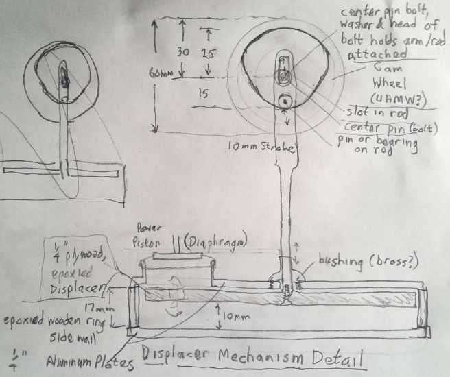 So
I
came
up
with another, simpler system with a "cam
wheel". The displacer will fall toward the bottom by itself (I trust)
and only needs to be pulled up. It is easier to show in the diagram
than to describe. I drew a 60mm diameter disk with cutouts at 25mm and
15mm outer radiuses and straight slopes between them to move the
displacer up and down 10mm. As drawn the displacer would sit on the
bottom for about 1/3 of the cycle, at the top for 1/3, and move between
them for 1/6 of the cycle each, up then down.
So
I
came
up
with another, simpler system with a "cam
wheel". The displacer will fall toward the bottom by itself (I trust)
and only needs to be pulled up. It is easier to show in the diagram
than to describe. I drew a 60mm diameter disk with cutouts at 25mm and
15mm outer radiuses and straight slopes between them to move the
displacer up and down 10mm. As drawn the displacer would sit on the
bottom for about 1/3 of the cycle, at the top for 1/3, and move between
them for 1/6 of the cycle each, up then down.
That would be at one end of
the flywheel shaft. Making it
of slick UHMW plastic would let the pin on the displacer rod slide
easily around the cam - or a bearing could be used to roll around it.
The piston/diaphragm would be driven from the other end with a regular
cyclical motion from an off center pin.
On one side the flywheel assembly mounting would be metal.
On the other side, to prevent magnetic drag, it would be wood (or?).
The mountings would hold the 3/4" ID bearings for the flywheel shaft.
An epoxy molded ring of coils for the generator would attach to the
wooden mounting.
(4th) On youtube I saw an interesting demo: it was a stirling engine
connected to a generator. But instead the generator was used as a motor
to drive the stirling engine. Instead of applying heat, the engine got
cold - frosty - on one side and hot on the other. That means a stirling
engine could be used to power a refrigerator. The two questions I would
have (in that order) are first, is it quieter than than a compressor
fridge, and second, what is the coefficient of performance? (I looked
into it later - more below.)
(5th) Having departed from the traditional designs, I came up with
something wilder: What if the displacer was well above the bottom, but
sealed all around the edges at the bottom of its stroke? It would just
let the water boil and build up pressure while it was closed. (If it
wasn't hot enough to boil water, the warming air would still build up
pressure.) It would be the "lid" on the inner pressure cooker. One
could go for the simple offset cam, but when the displacer hit the
bottom, say about 1/2 way down, a spring would start to compress as the
rod driving it continued down lower. Thus it would to enabled to be
closed for half the stroke while pressure built up, and open for half -
and beyond a narrow point, it doesn't matter how wide it's open. It
would be the "on-off" displacer action I was looking for, and it could
have a very short stroke - less actual motion and less noise. In fact,
since it would be closing against slight air pressure, it might close
very gently.
As it opens the steam is released into the upper chamber
and of course it cools as it expands (while driving the power piston),
and it cools more as it contacts the cool top of the cylinder. (That's
the place for the finned heatsink.) Despite the bottom still being
heated, the steam cools and condenses and drips back down.
Another way to do the same thing would be to have the
displacer under the lip instead of over. At the top of the stroke it
would be pulled up to seal it against the lip, and the pressure would
keep it closed. Before the bottom it would be pushed open, and it would
stay open because (once the pressure was released) there'd be nothing
to pull it up again. (OTOH, the pressure would then tend to "pop" it
closed, which would be noisier.)
The displacer would then be a lightweight flap, perhaps
hinged on one side. It wouldn't have to match the profile of the
cylinder at all. Even the 'cylinder' could be square or any shape at
all.
With this redesign, I decided the pressure cooker would be
the better vessel. Well, that was handy - a ready-made, sealed but
easily opened cylinder! I drilled out the center hole in the lid, which
somehow wasn't round near the bottom, to accept a 3/32" round steel rod
to move up and down. There was a simple connection rod to a displacer.
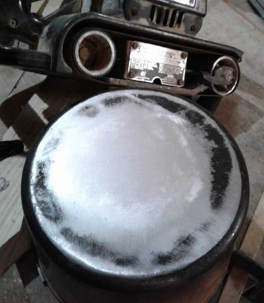 One problem with this pressure cooker was that it was
notably rounded on the bottom. Only the center touched the woodstove
surface. (I suppose they thought it would be going on a gas stove and
it
wouldn't matter.) I soon sanded off the brand ("Blaze"?) and model
number from the middle, and remembered only that it had said "Made in
Canada". But it was still quite rounded. I set it on a table - yup,
still a 16th of an inch off the table all the way around at the edges.
After a lot of sanding with a handheld power sander, it at least was
sort of flat toward the middle. I hoped it wasn't getting too thin in
the middle. At least it won't be holding much pressure.
One problem with this pressure cooker was that it was
notably rounded on the bottom. Only the center touched the woodstove
surface. (I suppose they thought it would be going on a gas stove and
it
wouldn't matter.) I soon sanded off the brand ("Blaze"?) and model
number from the middle, and remembered only that it had said "Made in
Canada". But it was still quite rounded. I set it on a table - yup,
still a 16th of an inch off the table all the way around at the edges.
After a lot of sanding with a handheld power sander, it at least was
sort of flat toward the middle. I hoped it wasn't getting too thin in
the middle. At least it won't be holding much pressure.
And by night, with the new idea for the "displacer" came a
new idea for the sequence: There could be just one arm coming up, with
the power piston and the displacer connected - the displacer still with
a spring, and on the underside of the separator. As the arm goes down
because the piston is going down, it reaches the point where it opens
the heated chamber.
Arrival: The Carmichael Woodstove
Engine
(6th) The idea continued to evolve and
change in my head rapidly up
into that morning. But by lunch time I had drawn two diagrams (the
second remedying a small problem in the first). If ever there was an
invention
"drawn on a napkin over coffee", this was it. It could no longer be
described as a Stirling engine. Rather, it had become what I might term
a "closed cycle steam engine". In keeping with Stirling I'll name it
after myself. (I know if it becomes popular everyone will just call it
"the woodstove generator" anyway.)
The pressure cooker was divided into upper and lower
chambers. A single cylinder with a piston (a lovejoy coupling - ?) went
up and down between them. A rod from the piston still drove a flywheel
above the unit.
Operation:
- starting with the piston (and flywheel cam) at the bottom,
pressure builds up in the bottom chamber owing to the woodstove heat
heating the air and steaming the water in the bottom of the pot.
( - Probably the flywheel will need a turn by hand to start it moving. )
- The pressure pushes the piston up (and up), causing its
connection rod to press up on the cam and rotate the flywheel.
- As the piston (and cam) reach the top, the gaps in the lovejoy
piston rise over the top of the separator.
- Compressed air and steam from the bottom chamber escape into
the top one. Pressure is equalized throughout the pressure cooker pot.
- The flywheel continues to turn by momentum, pushing the piston
downward again. Because pressure has been equalized, there is at first
little force slowing its descent. But with the heat still applied,
pressure starts to build again.
- By the time the piston (and cam) has reached the bottom,
pressure is building again.
- At the same time, the air and steam in the top chamber is in
contact with the outer walls and is cooling. The steam is condensing
back into water, which runs down the sloped separator to sit next to
the piston, and the chamber becomes a relative vacuum which helps draw
the piston up.
- The piston rises again. When it nears the top, the gaps open.
The pressure is equalized, and the condensed water drains back through
the cylinder to the bottom.
By night I had thought of a further refinement: If instead
of being tied exactly to the cam cycle, the piston is able to descend
rapidly from the top to the bottom, there will be little pressure and
vacuum built up to impede its drop and things should run more smoothly.
Then I would think that on the power stoke it should ideally be made to
rise more or less linearly to near the top. Perhaps I could make use of
that "cam wheel" idea after all?
Originally I was thinking of a lightweight displacer, then
a lightweight piston. But what could push the piston down on this rapid
downstroke? Maybe if it was heavy (like the lovejoy piece) and if the
friction in the cylinder was very low, it could fall by its own weight?
...Or should I just settle for the sinusoidal motion of
the offset cam? It has the advantage of simplicity and would probably
be quietest in operation.
(9th) I went out to the workshop to do a small job...
1. Replace the 1 inch bore "H" taper lock hub on the 10" magnet
rotor/flywheel with a 3/4" "H" hub.
2. File the slightly rusty 3/4" shaft a bit so the bearings would go on.
3. Drill and tap a hole in the end of the shaft to hold the offset cam
pin.
Time budgeted: An hour.
1. It turned out that the "H" hub had been specially turned to fit this
rotor. I had to duplicate this custom lathe job on the 3/4" bore hub.
2a. Bearings went on shaft okay.
2b. Then I tried to put the shaft through the rotor (3/4" "H" hub) and
discovered that it was actually a 5/8" shaft, not 3/4". Oops - I had
estimated
the size wrong.
2c. With no 5/8" "H" hub, I tried to fit in some shims to make the
shaft fit. I wasn't happy
with the result.
2d. I cut a length of 3/4" shaft.
2e. Since the bearings were much smaller and I (thought I) had no 3/4"
ID bearings,
I had to turn both ends of the shaft to 5/8" to fit the bearings on.
3. Drilling and tapping the end hole went okay.
Time taken: All day.
Then I thought, wait... I have some 3/4" "steady bearings"
mounted in pressed metal holders, that could be bolted onto something.
On looking I decided to leave one and change one end to the steady.
(10th) I had been thinking (a) that the sinusoidal piston motion would
doubtless be quieter than one that made rapid moves, eg, a rapid drop
down after a slow power stroke up. (OTOH it would have less power per
size.) And (b) that it would still be better if no pressure built up
while the piston was going down, since that pressure would be counter
to what was desired. That would need some sort of valve. With a
sinusoidal cycle and no valve, half the pressure would build up as the
piston descended (the flywheel keeping it turning against the pressure)
and the engine would be operating only off the increase in pressure as
the piston rose again.
One thing or another would be best to arrange: a valve
that stayed open between the chambers while the piston descended, or a
way for say 3/4 of the cycle to be the piston rising (power stroke) and
have it go down again in just 1/4 of the cycle, asymmetrically. If this
rapid drop down could be arranged, it would have the most power AND
there wouldn't be time for much pressure buildup, obviating any need
for a valve. But even the rhombic drive of some of the Stirling engines
was symmetrical overall. Was there any way to do it, even theoretically?
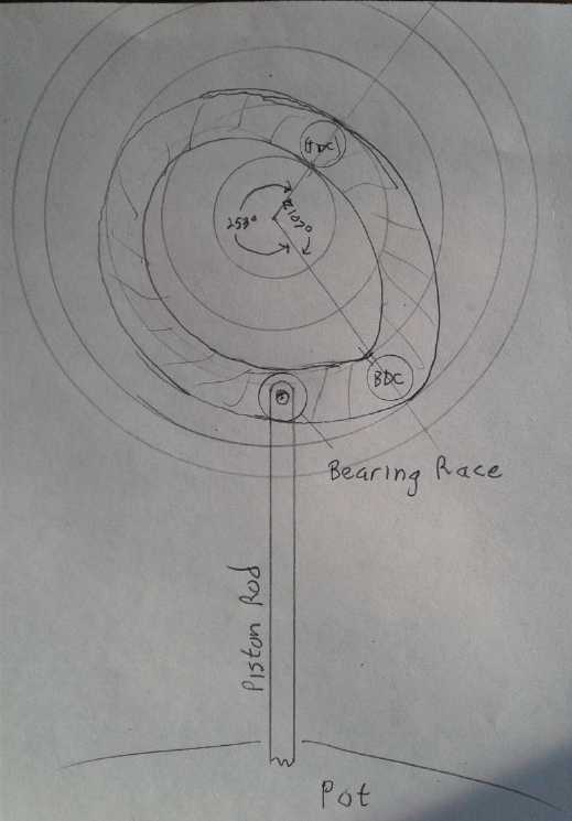 Let's see... On the upward power stroke the piston is
pushing the flywheel. On the return stroke, the flywheel is pushing the
piston. An sloping cam, perhaps? The piston rod would push straight up,
and the flywheel would turn based on the slope of the cam. (A bearing
on the end of the piston rod would be needed to reduce friction? or
some UHMW somewhere?) If the piston went from flush to about 1/8" above
to let the pressures equalize, its stroke would be about 28mm. So there
was the difference in height of the cam from bottom to top of stroke.
But the slope could occupy more than 1/2 the circle.
Let's see... On the upward power stroke the piston is
pushing the flywheel. On the return stroke, the flywheel is pushing the
piston. An sloping cam, perhaps? The piston rod would push straight up,
and the flywheel would turn based on the slope of the cam. (A bearing
on the end of the piston rod would be needed to reduce friction? or
some UHMW somewhere?) If the piston went from flush to about 1/8" above
to let the pressures equalize, its stroke would be about 28mm. So there
was the difference in height of the cam from bottom to top of stroke.
But the slope could occupy more than 1/2 the circle.
For the return stroke, the cam part would need to be
outside instead of inside, to push the piston down. It needed the same
28mm but over a shorter part of the circle.
I sketched it out. I made it go in from 44mm to 16mm from
the center from bottom to top. With the need to have an outside area to
push the piston back down, the cam wheel, if made circular overall,
came to a surprising 140mm (5-1/2") O.D. But I didn't see why this
arrangement couldn't make a great engine, that would push the flywheel,
rather linearly, for well over 1/2 the cycle, briefly releasing the
pressure at the top of the stroke, then rapidly returning to the bottom
(before too much pressure could build) for the next push.
If all the cam wheel bends are gentle, I have hope for
relatively quiet operation (in spite of hearing some pretty noisy
Stirling engines on Youtube as well as tiny silent ones) because the
only
percussive sound would be the "pop" or "puff" as the steam was released
from the
lower to the upper chamber, and that sound was contained inside a heavy
cast aluminum pressure cooker pot. Both sides of the piston are
enclosed, with only the connection rod sticking out of the pot. The
heavier the load, the stronger the "pop" would be. The less power with
the same fire on, the higher the RPM and the lighter the "puff". I'm
counting a lot on the heavy cast pot damping that internal "pop" sound.
(13th) At lunch I showed the drawing to
someone who suggested that
rather than having the flywheel slow down as it pushed the piston back
down, a counterweight could be placed on that side to help push. The
piston would have to push it up again, but the velocity would be more
constant. This seemed to make quite a bit of sense.
Later in the day I realized it would be better just to
weight the connecting rod. I already had a somewhat heavy piston in the
L095 lovejoy connector piece, but if desirable, another wieght could
simply be clamped onto the rod.
At the start of January I had the thought that the rather
special shape of the "air escape" bottom end of the 'lovejoy' piston
could be made in the cylinder wall instead if desired, and the piston
would then be replaced by a simple cylinder shape.
The Woodstove Engine as a Refrigerator or Heat Pump?
(7th) Having found from a youtube video in which a motor drove the
engine and the heat fins got heavily covered in frost, that the
stirling engine can be used as a cooler or
heat pump, I searched on that topic. Wikipedia had an article Applications
of
the
Stirling
Engine which went into it. I saw another youtube
video, and finally hit on a scholarly article on what I was looking
for, Coefficient of Performance of Stirling Refrigerators.
I confess that my eyes mostly glazed over the math
formulae presented. But thankfully a very useful set of figures was
given: For a temperature drop of 30 °C for temperatures around room
temperature, the "reversible" cycle COP was 10, "hybrid" was 9.2 and
"irreversible" was 8.2. Obviously these must be theoretical figures. I
am under the impression that Rankin cycle compressor refrigerators are
under
5 if not well under 5. (And so much for the efficacy of doing magnetic
refrigeration where the potential COP was also only around 5 - I'm glad
I dropped it!)
Another article (U of Canterbury) says that "Such machines
theoretically have the highest efficiency possible for any practical
thermodynamic system."
One question is: "Can such an engine (in real life) beat a
compressor fridge in COP?" and the answer is provisionally yes,
assuming one can come relatively close to the theoretical limits.
The second major question is: "Can such an engine be made
to run more quietly than a compressor fridge?"
If the answer to both these questions is yes, then such
refrigerators should definitely be developed. (And the next question
is: Why haven't they been?) If the answer to either
question is yes and the other is comparable, the answer is still yes,
they should be developed. If they are worse in either respect, they may
not be worth pursuing, especially if they aren't better in the other.
(I have recently found some higher performance peltier
modules on line for solid state refrigeration. They would be quiet and
I may well order a couple to try out in my peltier shallow chest fridge
and camping cooler, but the COP is
still much lower than the compressor - or Stirling - method.)
Another useful question is: "Can my new design be run as a
heat pump/refrigerator/cooler?" The answer would be yes. Instead of gas
expansion from heat pushing the piston up, a motor turning the flywheel
pulls it up, creating a vacuum in the bottom chamber and compression in
the top one. Compression heat is transferred into a "regenerator"
(internal heatsinks?) and from there dissipated to the outside in the
external heatsinks. (Usually a fan would be used. It could be on the
driving motor.)
The reduced temperature created by the vacuum in the lower
chamber is transmitted through the bottom of the pot, which would be on
the top of the fridge. Heatsinks would extend from under the bottom of
the pot and thus to inside the fridge (or freezer), and a fan would
blow the cooled air around the compartment.
When the piston reaches the top and the air in the engine
compartments is mixed, the resulting air temperature would depend on
the relative coolness remaining in the lower chamber versus the
relative warmth in the upper. If the upper chamber is continually
vented to the room and the lower one is in a gradually cooling fridge
(or freezer) space, one can expect the mixed air inside to gradually
cool to somewhere midway between the room and the fridge temperatures.
There is more to making a cooler with a high COP than
this. When the cold air and the warm air mix, they should do so through
an internal 'heat exchanger' - this seems to be really what was meant
by the term 'regenerator' in the article. When mixed this way, when the
pressures are equalized and airflow stops, the bottom compartment will
still be pretty cold and the top pretty warm. Thus they will start each
cycle with more temperature advantage than the last.
I have no plans to get into creating a unit for cooling or
heat pumping at this time. It seems like an exciting prospect
especially for very low cost home heating/cooling, but the
woodstove electricity generator is
already an unexpected additional project, one of too many. And as an
engine, the "Carmichael Woodstove Engine" will have the special
advantage of H2O undergoing phase changes between water and steam,
liquid and gas, which should give it much more power for its size than
a Stirling engine. The temperatures involved in refrigeration or home
heat pumping are too low to take advantage of this.
If I can figure out how to include one, a heat
exchanger/regenerator would probably boost efficiency. How much would
that help? After all, there is no such thing as "waste heat" from a
woodstove in winter!
Electricity Storage (Batteries)
Turquoise
Battery
Project:
Long
lasting,
low
cost,
high
energy
batteries
Gold Electroplating
On the morning of the 11th
the gold plating solution finally arrived. I decided to stick with the
present test cell size for now but to tip it face up. Then I wouldn't
need to glue the face on to keep it from leaking. So I just needed to
gold plate a piece
of copper the same size as previous copper and graphite sheets. And
redesign and make a new shell.
While I was doing a few things before starting to plate,
the power went out for 5 hours.
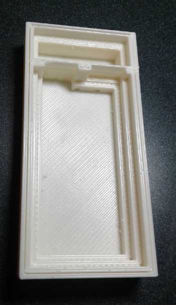 (12th) I
decided if I was going to make a "lying down" flat test cell,
I should do that before starting on the electrodes. Even if they were
the same size the terminal tabs would be different. Somehow the day
went by - again- but I got it designed and made in the evening.
(12th) I
decided if I was going to make a "lying down" flat test cell,
I should do that before starting on the electrodes. Even if they were
the same size the terminal tabs would be different. Somehow the day
went by - again- but I got it designed and made in the evening.
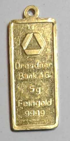 (14th) I re-read the gold
plating instructions. They said that it was
best if the anode was about the size of the object being plated. Also,
if one used "scrap gold" for the anode instead of stainless steel, the
solution would last longer. The solution being 200$, I sacrificed a
little 5 gram gold pendant I had, running it through the jewellers
rolling mill a few times until it was much longer, if not much wider.
Hmm, that was worth... about 320$ spot gold value. Well, all for the
cause!
(14th) I re-read the gold
plating instructions. They said that it was
best if the anode was about the size of the object being plated. Also,
if one used "scrap gold" for the anode instead of stainless steel, the
solution would last longer. The solution being 200$, I sacrificed a
little 5 gram gold pendant I had, running it through the jewellers
rolling mill a few times until it was much longer, if not much wider.
Hmm, that was worth... about 320$ spot gold value. Well, all for the
cause!
L: plain copper sheet, gold plated copper
sheet, gold anode.
The eye of the pendant was useful. I put a loop of copper
wire through it and thus had a good way to hang it from the top of the
beaker, also making electrical connection.
I tried to follow the instructions. I got the solution
heated up to 60°C. It said 2 to 4 volts, current .005 amps per
square inch. Surprisingly low current. It said it in 2 or 3 places. To
get the current down to that low value I had to reduce the voltage to
about 1.3. And it said 30 to 60 seconds, but there was precious little
plating going on in that time. I finally decided somebody had slipped a
decimal point and the current was supposed to be 50mA/sq.in., not 5.
(Maybe it was originally written "0.05 amps" and some unknowing person
changed it to ".005"?)
To get that I had to raise
it to over 2 volts. That was
making more sense. Even at that I'm sure I had to leave it over 60
seconds to get a bit of yellow color on the copper. I was thinking of a
nice solid yellow like on printed circuit board edge connector fingers,
but it just wasn't there. But then to protect the copper it didn't need
to be very thick. It just needed to cover ALL of it, 100%.
To
appearances it was somewhere between copper and gold in color. But one
could clearly see on the tab where the gold plate ended. I decided to
leave it at that.
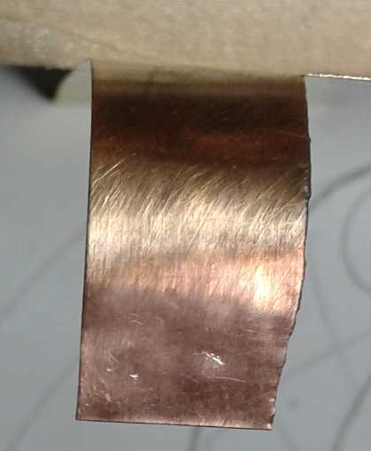 Terminal tab plated to half way up.
Then I set it into the 3D printed cell case and
looked. I wondered if I had gone high enough up the tab. I went back,
reconnected, and dipped in just the tab, upside down, to make sure at
least most of the tab, the part that might still be inside the cell,
had at least a bit of coverage. I'm tired of connection tabs corroding
off. When it happens it doesn't matter that the rest of the electrode
is still good.
Being the same size, an old separator
grill fit right in.
I now awaited the pure zinc sheet before putting together
a
new cell. Some came on the 21st - too late to do anything before
Christmas. More came after new year - I had ordered some from 2 or 3
places.
Charge The Future Battery Challenge Rejection
On the 20th an e-mail came from Natural Resources Canada /
Charge the Future Challenge.
Somehow I was pretty sure what it would say even before I
opened it. The application was rejected. Perhaps it was because it came
in December instead of January. That meant they had rejected it early
without even any serious thought that they might fund it.
It puzzles me what goes on in the realms of finance. They
claim they want to improve the future. They said they will fund up to
five projects. Have there been more than five of Canada's best
inventors working for a decade on making improved batteries, who seem
to be getting close to production stage? If that isn't just what they
want - almost beyond their best hopes - what are they really after? It
often seems more like government
wants showcase art with a good spiel that will never go anywhere, and
are afraid of anything that might actually make a real difference.
Of course, one of the reasons given for the challenge was
that the battery industry is growing rapidly in scale and monetary
value. Perhaps they are actually afraid of something that might reduce
the overall monetary value of the industry by being cheaper, easier to
produce and better? Or perhaps they have put themselves into a box of
fixed ideas and are unwilling to think outside of it. A move away from
element #3 just isn't something they are prepared to contemplate.
Or could it be, once again, simply that my name was "Mr"
Carmichael instead of "Dr" Carmichael and I wasn't associated with a
university? One may think I am biased, but an impression has grown on
me for decades: It seems to me that those associated with disbursing
funding in any any way associated with universities hate discovering
that there are knowledgeable, talented people who didn't come up
through the university system, and they give them the cold shoulder. I
often
think they are prejudiced. And of course one "good word" from a
university 'expert' would probably sway everyone else - "It's been
repeatedly proven that zinc electrodes don't last." Who would dare
argue against him?
Of course one might always hold out some small hope that
the rejection for this funding portends some other interest, perhaps in
private funding, or that the application might be passed on to some
other government department with a more direct interest. Of perhaps I
should be launching a "go fund me" campaign or something through social
media? Perhaps there's nothing like the power of lots of people with
some trust and ideals, each expressing some small and very affordable
token of financial interest.
Just one time in my life, in 1985, did someone in
authority believe me when I said we could do something, that we could
create a computer to control and monitor heating and ventilation etc.
in schools before such a thing was available commercially. Facilities
manager Keith Hawkins, P.Eng, hired me to pursue his project, and for
the only time I got a salary and a budget for parts, and over about
three years I went on to do just that and install a very fine product
(including as evaluated by others in the field) in several schools. But
he ran into the same hurdles as I always do when he tried to find money
to commercialize this fine product. (What this high official of the
Victoria School District said about his meeting
with NRC-IRAP was pretty much unprintable.)
We will grind on toward battery production. A little
funding could have gone a long way toward expediting the process. If
you grind on slowly enough, someone else will eventually get there
first. Someone else has come up with an "ultra-efficient electric car"
which I've worked on for free with no budget for so long. (Albeit their
stated price for their car leaves lots of room for commercializing my
goal - "simple ultra-efficient EV conversion" components.)
If someone does get a similar battery first, I will at
least have the satisfaction of knowing there's every chance they used
Turquoise Energy News to help them get there. Marconi got the
credit
for inventing radio, but he did so after being taken in as a new
immigrant by Tesla as an apprentice, and then using Tesla's radio
designs. (Marconi had the gall to try and patent it, but it was noticed
that it was almost the same as Tesla's prior patent.) In this
millennium the stories of Tesla's works over a century ago have started
being seen by the
public, but without him we would not have had radio when we did. It
might have been decades later. (Not to mention the electric power grid
we all enjoy. The free energy he harvested has been kept from the world
so far - apparently in order that we not destroy ourselves. Tesla
offered a "death ray" to the USA during world war two, but somehow no
one paid attention until he died (January 1943). Perhaps just as well!
Then his apartment was raided and all his papers seized, but at that
point the design may have been more in his head than detailed on
paper. But once again I digress.)
I keep at it because although I haven't yet proven it, I
believe that once developed, this battery technology will not only be
cheaper
but should last forever and will be definitely superior to lithium
types.
http://www.TurquoiseEnergy.com
Haida Gwaii, BC Canada