Turquoise Energy News #140
covering
January 2020 (Posted February 8th 2020)
Lawnhill BC Canada - by Craig Carmichael
www.TurquoiseEnergy.com
= www.ElectricCaik.com
= www.ElectricHubcap.com
Features:
* Open Loop, Free Air Heat Pumping: COP > 10? - or: How to
Heat a
Building Really, Really
Cheap! (see: Month in Brief, Other Projects)
* 12 Years of Green Energy Projects in Review (see "In Passing")
Month
In
"Brief"
(Project Summaries etc.)
- Brr!
- Free Air Heat Pumping - Theory - Heat Pumping Experiments - Meanwhile
in Other News - Bringing a Dead NiMH Battery Back to Life
In
Passing
(Miscellaneous topics, editorial comments & opinionated rants)
- Von Braun and the Apollo Moon Landing Project - 12 Years of
Energy Projects in Review - Reversing Desertification - Small Thots:
Columnating out-of-line binoculars, Hair mites, Earth heat... - ESD
- Detailed
Project Reports
-
Electric
Transport - Electric Hubcap Motor Systems (No Reports)
Other "Green"
Electric Equipment Projects
* HAT & CAT Plugs & Sockets
* Very High COP Open Air Heat Pumping
- Cooling - Heat Pump Heating - Some Simple Tests - Experiments -
Copper Pipe, Soldered Copper Fins - A Test - More Compressed Air Piping
and Test 2 - Outer Ducting and Test 3 - Building-to-Outdoor Heat
Exchanger and Tests #4 - Michelin Air Compressor Tests - Air Compressor
Noise Solutions? - Custom Air Pumps? - Refrigerator Air Pump
Electricity Generation
* My Solar Power System: - Monthly
Solar Production log et cetera - Notes. (December & January:
trivial power output!)
* "Carmichael's
Woodstove Engine" (& generator) -- Called off for now for
greener pastures & easier projects.
* An Experiment: Woodstove Electricity with Thermoelectric
Generators
(TEGs)
Electricity Storage
* Turquoise Battery Project
(Mn-Zn or Ni-Zn in Mixed Alkaline Salt electrolyte)
- Thinner copper current collector - nickel electrode - pure zinc
electrode - Nickel-manganates Again - Low Currents - Back to Graphite
Felt? - Chemistry seems fine but Mushy Electrodes Don't Conduct Well
January in Brief
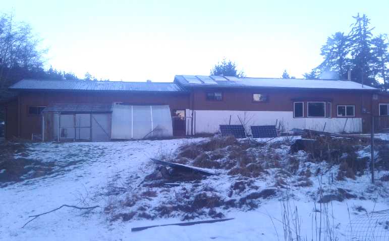 House with some snowed-over solar
panels on
the roof.
House with some snowed-over solar
panels on
the roof.
Some snow had melted or slid off the bottoms, but
they don't produce unless the whole panel is clear.
Best Laid Plans and all that: It's
the Weather
After returning from my Christmas holiday I had intended
to
carry on with the model of the ground effect vehicle, but I came back
with a nasty chest cold. I put heat and steam on
in my bedroom at night for some days. (yet more electricity!) I sat
down and
looked into the Stirling engine heat pumping idea. This led to thinking
of
an exciting way to refrigerate, followed by an even more exciting way
to heat a building, for exceptionally low cost. These dominated my
creative thoughts.
And the weather was cold, varying from -5 to -10°C for
a couple of weeks. I could hear 2 or 3 chainsaws in the neighborhood, I
thought
to cut more firewood in the unexpected cold. Luckily I was already
short of it and I had bought a cord of fairly dry firewood just before
Christmas. (On the night of the 13th-14th it dropped to -10.2. That's
the coldest I've ever been in in 47 years on the west coast - if only
by a degree or so and I'm farther north now.) I left the kitchen sink
running a bit to make sure the pipes coming in from the well through
the unheated garage didn't freeze. (Some other peoples' water did
freeze.)
ACK! My potatoes! Since it doesn't usually get so cold I
had
left them in the ground, digging them up as needed. Now they were in
danger of freezing! I went outside for a couple of short sessions,
throwing off big slabs of frozen dirt about 3-4 inches thick and then
digging through the soft sandy soil underneath. There were too many in
the frozen top layer, and I sliced through too many with the shovel,
and doubtless I missed too many. (Weapon of choice for potatoes is
normally a pitchfork: you'll skewer a few, but you'll turn them up
without slicing a bunch of them in half.) I wasn't a day too soon as
there was thick snow the nest day. It would have gone better in
December - if I had guessed what was coming. I only got the main patch
- there were still others. Oh well, 6 Kg of potatoes is 6 Kg of
potatoes. Some had been frozen and went mushy, but most were good.
Sitting anywhere but the livingroom where the woodstove
was - and preferably next to it - wasn't comfortable. So
I dabbled at things that didn't require going outside or into the
workshop much... or even into the kitchen. Especially things for which
I could sit near the stove to do some of the work. On the 13th I
noticed that electricity consumption had gone WAY up that day, from 40
KWH
to 90. I finally realized the house baseboard heaters, set to 10°,
must have come on at night when the fire was low. They were
using far, far more electricity, to keep the house less warm, than my
new plan for heat pumping would have if it had been already working
instead of
just a concept.
On the 15th I checked my "root cellar" storage room. It
usually maintains a nice, cool temperature but now the thermometer said
35°f... 2°! I put a 425 watt heater down there to keep the room
with its many gallons of paint and some food from freezing. I can only
be glad I'm not on the prairies. Edmonton where I grew up was almost
-40°c (= -40°f), even colder than the coldest day when I was
going to
school in the 1960s, -30°f or -34°c -- "-90 [°f] with
wind chill". (I remember it well. That was before
Canada went metric)
We have by no means seen the end of unprecedented weather
and broken all-time records. It's global. IMHO there are three main
forces at work: Unnatural high stratospheric cloud cover being caused
by jet aircraft which are heavily disrupting the global wind
circulations and precipitation patterns (TE News #109 etc), global
warming, and the grand solar minimum ("GSM") with the
sun being slightly dimmer than usual for a period of (hopefully only) 2
or 3 decades. It seems to me that the first of these is the most
disruptive.
Things improved for some days in the later part of the
month, but there was just one sunny day where it was nice to be
outside, and on the night of the 31st it snowed again, with the
temperature around freezing.
Free Air Heat Pumping: How to Heat a Building Really, Really Cheap
Reading in a paper that Stirling engines might potentially
get a Coefficient
Of
Performance (COP) of 8 to 10, that is, pump 8 to 10
times as much heat from a cool place to a warm place as the electricity
being used to pump it with a 30° temperature
rise or fall, was really exciting. Why didn't we already have such
equipment, then? I just
couldn't drop the subject in my mind. Then I thought, why a Stirling
engine? When powered by a motor, all it did was shuffle air around, and
perhaps not even as effectively as it might. One could shuffle air
around in simpler ways. What about just a plain air compressor using
open air?
On the 6th I started writing ideas down, and the more I
looked into it, and the
more thought I gave to it, the more exciting it seemed. I started
thinking
of refrigeration, but soon turned to building heating. It was
so much
simpler than a refrigerant gas/liquid heat pump system that even if the
COP wasn't higher, it should be cheaper and so would have broader
application. And the COP
looked like it could be substantially higher. If a 'regular' heat pump
had a
COP of 2 to 4 depending on temperature differentials, might free air
(at this point based
solely on the Stirling engine paper and expecting similar) be 6
to 12, using 1/2 or 1/3 as much energy to do just as much heating of
cooling? But it turned out the Stirling engine paper seemed to have
been
quoting almost theoretical maximum COP, not what was likely to be
attained by
actual heat pumping equipment, especially pumping air and with amateur
homemade
equipment.
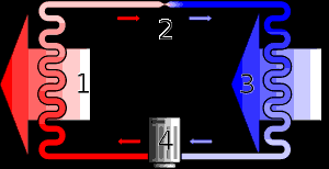 In a typical closed-loop heat
pump, a
refrigerant
In a typical closed-loop heat
pump, a
refrigerant
is pumped between outdoors and the building.
The cooled refrigerant must be reheated from
below the outdoor temperature to above
room temperature to heat the building.
By the time I realized that, I had also realized that
by
using open loop heat pumping with air instead of a closed loop
refrigerant based system, one might
actually get a real COP above 10 - even 15 to 20 or more
by further heating indoor air instead of heating
air from outdoor
temperature! The lower the temperature rise, the higher the COP. So
one might perhaps get (eg) 1200 watts of heat
from
each 100 watts used to run the compressor. This was the essential
conceptual
breakthrough. Soon a few more bits fell into place to enable that to
work well.
In northern latitudes heating is the great energy
consumer, in winter exceeding all other energy uses combined including
transport. The possibility of attaining "unheard of" COPs by
doing just a small temperature rise seemed
unbelievable at first, but I didn't see
a flaw in it. It seemed like such an exciting idea, to be achieved with
such potential simplicity, as to be a game changer for home energy use
- the energy equivalent of going from incandescent light bulbs to LEDs,
but for the much larger energy use of space heating.
How could I not look into it? I learned more. (What a
fantastic resource the internet is, and accessible from home!)
The Theory
I finally found the essential, simple formula for theoretical
maximum COP. Temperature units must be in
absolute temperature (°Kelvin, °K = °C+273):
Thot
COP = ----------
(Thot
Tcold )
The denominator is known as the "lift", the number of
degrees (here °K or °C are the same) by which one wishes to
raise a
temperature. To pick a simple round number for Thot, Earth's
temperature is around 300°K. (That's 27°C.)
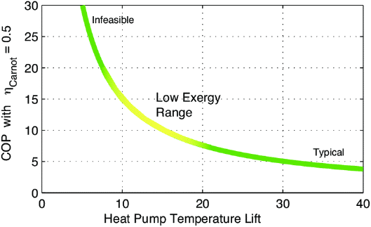
Graph showing COP potential for
heat pumping at various temperature "lifts",
assuming 50% efficient heat pumping. But: "Infeasible"
looks feasible!
 So
if
one
wants to heat ("lift") outdoor air by 30°K (=
30°C), eg, to heat from freezing air temperature up to 30°C
to be warm enough to radiate heat into the building to get a
comfortable 23°C or so room temperature, 300 / 30 = 10 theoretical
COP. Inefficiencies in closed loop, refrigerant based heat pumping
apparently reduce
the actual COP to around 2 if it's below freezing outside, to 3, or
often 4 or higher if it's not very cold outside. (When the most heat is
needed
the COP is lowest. Note: Could newer equipment do a little better
than my old statistics?)
So
if
one
wants to heat ("lift") outdoor air by 30°K (=
30°C), eg, to heat from freezing air temperature up to 30°C
to be warm enough to radiate heat into the building to get a
comfortable 23°C or so room temperature, 300 / 30 = 10 theoretical
COP. Inefficiencies in closed loop, refrigerant based heat pumping
apparently reduce
the actual COP to around 2 if it's below freezing outside, to 3, or
often 4 or higher if it's not very cold outside. (When the most heat is
needed
the COP is lowest. Note: Could newer equipment do a little better
than my old statistics?)
If instead we can merely heat the indoor air from
23 to 30
at the radiators, that's only a 7° "lift". 300 / 7 = 43
theoretical COP. Given even just 25% equipment efficiency
overall, we still get an actual COP of 11: eg, 1100 watts of
heat for
100
watts of electricity. If the equipment is more efficient, it may go up
from there. With a fabulous radiator system one might need a lift of
just
3°, giving a theoretical maximum COP of 100: 10,000 watts of heat
from 100 watts of electricity!
The questions arose, and then the answers. How can one
just
heat pump the indoor air? Doesn't the air finally come out of the
system at room pressure, chilled as it decompresses? The heat pumped is
chilled again! That's where the open loop system has the advantage: it
can discharge the cooled air to the outdoors. So overall heat from the
outdoors is transferred into the building.
That is the essential, but there's still another
improvement to be had. Since
outside air is drawn into the building to replace what the compressor
uses, one can add a building-to-outdoor heat exchanger (or just
"outdoor heat exchanger") instead of just letting it suck cold air
through
the cracks. The
outgoing air warms
the incoming air, while the incoming air cools the outgoing air. Then
when the outgoing air, now cooled to almost outdoor temperature, is
decompressed to the outdoors, it will be colder than the outdoor air.
But the heat exchanger passively raises the temperature,
and the heat pump only heats room temperature air up a little
warmer.
So the open loop, free air heat pump system has three main
components.
1. The prime mover
is an air compressor. It is (at least thermally speaking) inside the
building
being heated. As air is
compressed, it contains the same thermal energy but in a smaller and
smaller space. If it's compressed into half the space at double the
pressure, it theoretically doubles in absolute temperature. But the
much denser solid materials of the compressor cylinder, piston and
pressure tank
quickly absorb this excess thermal energy and warm up, so it takes a
lot of air to warm things a little. But it is heat that came from the
already warm building air, not from the electricity running the
compressor.
2. The second component is the radiator - a heat
exchanger between the warmed, compressed air and the room air. This (at
least in
my prototype) is copper pipe with copper
fins, all inside a thin walled aluminized flexible dryer hose. The
compressed (and
hence a little warmed) air flows continually from the compressor
through the
pipe, under full pressure all the way. Its warmth is transferred from
the pipe via the fins into the dryer hose around it. The dryer hose
is thin walled and not insulated, and a small fan also blows the air
through the
hose/duct and out the end. Moving air transfers heat to the
room air much better than just passive convection and radiation from
the pipes,
minimizing the
"lift" needed to heat the radiator enough to heat the indoor air, and
hence maximizing the COP.
3. The third component is the building-to-outdoor heat exchanger. The
workings of these are long and well known since the 1970s(?). (Thanks
ASHRAE trade shows!) Inch by inch as the air comes in, it gets a little
warmer until it's (almost) room temperature, and inch by inch the
outgoing air gets cooler until it's (almost) outdoor temperature as the
two exchange their heat. (I've seen manufacturer's claims of 90%
efficiency.)
The unit should work without an outdoor heat exchanger,
but cold air being
sucked in from outside would add to the heating load. "Portable" single
duct air conditioners also work, but similarly the outside air they
draw in as the duct expels building air, adds to the cooling load and
they lose efficiency.
 The unit in
this case is like the radiator pipes
except its outer duct is insulated. The compressed air, having heated
the living space, is down (almost) to room temperature. The pipe is now
routed through the outdoor heat exchanger, where it is cooled to
(almost) outdoor temperature. The pipe ends outdoors and pointed away
from the incoming air. The
compressor is using air from inside the building and exhausting it
outside, and so air is
drawn in from outdoors through the outdoor heat exchanger's outer duct.
So as the compressed air is exiting the building, it is warming the
incoming air to (about) room temperature while itself being cooled.
The unit in
this case is like the radiator pipes
except its outer duct is insulated. The compressed air, having heated
the living space, is down (almost) to room temperature. The pipe is now
routed through the outdoor heat exchanger, where it is cooled to
(almost) outdoor temperature. The pipe ends outdoors and pointed away
from the incoming air. The
compressor is using air from inside the building and exhausting it
outside, and so air is
drawn in from outdoors through the outdoor heat exchanger's outer duct.
So as the compressed air is exiting the building, it is warming the
incoming air to (about) room temperature while itself being cooled.
At the very end of the long compressed air pipe, outdoors,
is a nozzle where
the air is decompressed, which further cools it, and released. Thus the
air actually exits the
system below the surrounding outdoor air temperature. So the building
is heated while the outdoors is cooled just
like with other heat pumps. But here the pump itself only heats indoor
air. The outdoor heat exchanger has pre-warmed the air to help make an
extreme COP possible - regardless of outdoor temperature.
(I used square aluminum fin pipes I had already made.
Probably
not optimum. And the outer duct ended up being a bit narrower than I
had intended.)
Heat Pumping Experiments
I ordered a "highest flow capacity" plug-in 120 volt air
compressor: over 4 CFM at 90 PSI. (MORE money going out, ahrg!) I had
hoped
for a quieter one
than the piston type, but
the quieter and supposedly more efficient (now I have my doubts)
helical screw, scroll and
centrifugal types seem to be made only in very
large sizes.
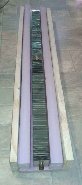
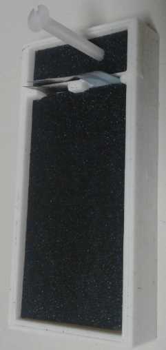
And I made a short "stegosaur" finned radiator pipe with
diagonally oriented, soldered-on copper fins to catch the air going
along in the duct outside the pipe, about 2 feet long. This
proved very tedious and they had less than an optimum grip (a few fell
off) and thermal connection, so I decided I had to make a jig(s) to
simplify and
improve the
process before I did any more.
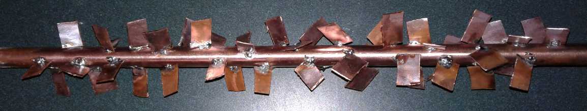 "Stegosaur" finned pipe
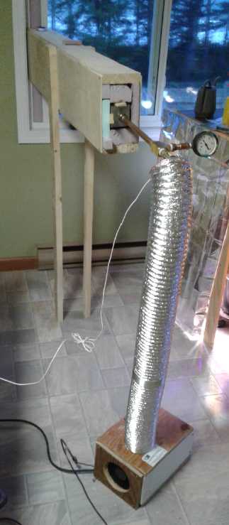
The "Star Wars Cannon" setup. It doesn't much
matter whether the body of the outdoor heat
exchanger is inside or outside, so I just set
the end up against the window, opened a bit.
 Later
in
the
month I thought of my small lab
vacuum/pressure pump.
I bought various pipe fittings, and made a mini heat pump unit with it,
making and testing one component at a time. The heart was a plywood box
with the compressor and a fan to blow air through the duct. (I plugged
the 36 volt fan into my DC solar power system outlet.) On the 26th I
completed the
last one, the building to outdoor heat exchanger, and in the evening I
tried it out in the kitchen/dining area with no other heat on and both
doors closed so it wasn't just being heated from other areas through
the doors.
Later
in
the
month I thought of my small lab
vacuum/pressure pump.
I bought various pipe fittings, and made a mini heat pump unit with it,
making and testing one component at a time. The heart was a plywood box
with the compressor and a fan to blow air through the duct. (I plugged
the 36 volt fan into my DC solar power system outlet.) On the 26th I
completed the
last one, the building to outdoor heat exchanger, and in the evening I
tried it out in the kitchen/dining area with no other heat on and both
doors closed so it wasn't just being heated from other areas through
the doors.
It was hard to tell what the effect was. The air coming
out the indoor radiator hose hose was only
2-3 degrees above the air going in, but it was a fair amount of air
being moved. The room temperature wasn't rising. But then it was
cold out, 4°C, and the space was mostly exterior
walls/floor/ceiling. How
effective was it really? I ended up by running several tests measuring
only the room temperature, one after another, with each test for one
hour:
Test
|
Start Temp.
(degrees C)
|
End Temp.
(after 1 hour)
|
Rise/-Drop |
Heat Pump
|
17.1
|
17.0
|
-.1
|
No Heat
|
17.0
|
16.0
|
-1.0
|
Heat Pump
|
16.0
|
15.9
|
-.1
|
425W Radiant heater
|
15.9
|
16.1
|
+.2
|
No Heat
|
16.1
|
15.5
|
-.6
|
It can be seen that without heat, room temperature
dropped. The heat pump almost kept it steady, so it was obviously
having some effect. The 425 watt radiant
heater managed to bring it up slightly. By comparing it with the
radiant
heater result, I conclude that the heat pump with the 75 watt
compressor must have been pumping in around 300 to 375 watts of heat.
That's a COP of 4
to 5. That's just a prototype with a compressor that works but is
probably not very efficient. (It keeps running but won't rise above
25 PSI. I was using
17 PSI to get some flow and still have some pressure. A substantially
higher pressure would probably be more ideal.)
The next evening I tried
again with my big compressor, but I only found a thin tube (~1/8 inch
ID?) to connect it to the piping. The compressor got hot instead of the
piping, and the pipe was substantially warmer than the air it was
supposed to be heating so it didn't transfer even that heat to the air
very well, and the result was unsatisfactory. The 800 watt compressor
seemed to heat the room less than 900 watts worth of radiant heaters. A
second experiment connecting straight to the compressor tank with 1/2
inch copper pipe wasn't noticably better. If I hadn't tried the
previous experiment, I might have concluded the whole thing didn't
really work. But it was pretty obvious that most of the heat was
somehow trapped inside the compressor, from which it simply radiated.
(Now I think the pressure inside
the compressor cylinder was much higher than what I was allowing in the
pipe, and so there was far too much flow. I should have run with much
higher pressure to match the compressor, with less flow.)
The next step will be to make a jig for making copper
finned radiator pipes, and then to try again with much more radiator
pipe and duct.
What about compressor noise? That will have to be dealt
with before the system is commercially acceptable. (I discuss it a bit
in the 'detailed report'.) On February 1st I got an 80 watt fridge
compressor at the scrapyard. It's quiet enough to use. If I can really
get 800 watts or more of heat from it, that will be great! (It should
work, but it's still hard to imagine!)
As a side note, in doing a little further investigation I
found where someone suggested on a discussion list that instead of just
venting compressed air to the outdoors to decompress it, it could
be decompressed through a turbine to generate electricityas it goes! I
don't know
how worthwhile this would be with a small home system, but it would
recover even some of the little energy used to compress the air.
Factoring this in
would further raise the overall effective COP - could it really hit 100?
Meanwhile in Other News
 On the 10th I
noticed that nearly 1/3 of the month was
already gone on heat pumping theory and I turned to other projects,
starting with trying out
the higher temperature nylon printing filament for CAT and HAT
electrical sockets. That went well. Mike pointed out that if I 3D
printed a few plugs and sockets, they could be mass produced by making
a silicone rubber mold and casting them in epoxy. And that epoxy was
probably high temperature enough, or perhaps could be with
an additive. Now we're talking real, low cost production! Perhaps for
battery cases, too?
On the 10th I
noticed that nearly 1/3 of the month was
already gone on heat pumping theory and I turned to other projects,
starting with trying out
the higher temperature nylon printing filament for CAT and HAT
electrical sockets. That went well. Mike pointed out that if I 3D
printed a few plugs and sockets, they could be mass produced by making
a silicone rubber mold and casting them in epoxy. And that epoxy was
probably high temperature enough, or perhaps could be with
an additive. Now we're talking real, low cost production! Perhaps for
battery cases, too?
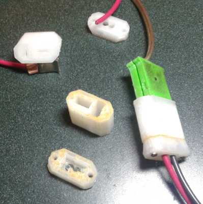
What didn't go very well was putting in and connecting the
pins. The crimp rings bulged out too far to the sides after crimping
the wires to the pins. I widened the recesses a bit to make more room.
This was however making the whole socket thicker and wider.
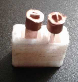
 Later in the month I did a plug.
It still didn't go together so easily, so I further adjusted the design
for next time. And another adjustment in the cap - a larger hole for
the exit for heavier wire. They're getting better. But fatter. The
earlier plugs and sockets for soldered-on wires (green, above) are
considerably
smaller.
Later in the month I did a plug.
It still didn't go together so easily, so I further adjusted the design
for next time. And another adjustment in the cap - a larger hole for
the exit for heavier wire. They're getting better. But fatter. The
earlier plugs and sockets for soldered-on wires (green, above) are
considerably
smaller.
 On the 12th I decided that
funding rejection or not, I should put
together another battery cell with the gold plated copper and the new
pure zinc sheets and try it out. This zinc behaved quite differently in
hydrochloric
acid, which showed what impure crap the old stuff I'd been using was. I
had trouble with the cell leaking - again! Sigh! That's
disheartening and I set it aside.
On the 12th I decided that
funding rejection or not, I should put
together another battery cell with the gold plated copper and the new
pure zinc sheets and try it out. This zinc behaved quite differently in
hydrochloric
acid, which showed what impure crap the old stuff I'd been using was. I
had trouble with the cell leaking - again! Sigh! That's
disheartening and I set it aside.
But I planned a new 106 x 106 mm flat battery case. The
new Cura slicer would doubtless make cases that wouldn't leak. The pure
zinc sheets came in 100x100 and 140x140mm. (4"x4", ~5.5"x5.5") So
(counting
outer walls) 106x106 should be a good small production size. The zinc
sheets would be on the bottom, so if graphite felt was used it could be
on top and wouldn't have to bend up much to make a terminal. They
should turn out about 7mm (just over 1/4") thick/tall.
Then I tried a copper oxide electrode in the plus side, then two of
nickel manganates again. In all cases conductivity was poor. Under load
the voltages were low and it didn't last long. The last one with the
powder in graphite felt, wasn't much better than the others. But with
it if I put weights on the cell, everything improved, and it improved
markedly if I leaned on it. It supplied load for much longer at higher
voltages. It seemed the chemistry was fine in each case. It was the
mechanical aspect that needed something.
I looked at some old issues of TE News and found that I
had been getting much better results in 2013-2014, probably from
torching the positive electrodes before I put them in. That presumably
"sintered" many of the particles together so the whole piece (even if
it stayed crumbly and fragile when handling) didn't just swell up and
everything lose connectivity once it was immersed in the electrolyte.
How easy it is to forget things after enough time goes by. If that
works I should finally be able to put together real, working batteries
now. I suppose if I had stuck solely or at least more heavily to
battery development I might have had it all working years ago and not
had time to neglect and then forget various details between experiments
sometimes months apart. But I hadn't really "connected all the dots"
and I confess I got rather discouraged for
quite a while.
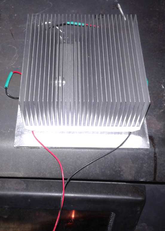 Having put the
woodstove closed cycle steam engine generator on hold in favor of the
heap pump project, I decided to (at long last) try a thermo-electric
generator (TEG) on the woodstove idea, little promise tho it seemed to
have. I could make four modules with four TEGs each, wire them in
series, use a DC to DC voltage boost converter to get a regulated
output, and feed that into the solar power system through the 36 volt
HAT receptacle near the woodstove.
Having put the
woodstove closed cycle steam engine generator on hold in favor of the
heap pump project, I decided to (at long last) try a thermo-electric
generator (TEG) on the woodstove idea, little promise tho it seemed to
have. I could make four modules with four TEGs each, wire them in
series, use a DC to DC voltage boost converter to get a regulated
output, and feed that into the solar power system through the 36 volt
HAT receptacle near the woodstove.
But I put one together and found that it was much harder
than expected to keep the upper heatsink cool. The TEGs passed a lot of
heat through from the stove. And anyway the output seemed pretty dismal
- 3 or 4 watts, so it would have been under 20 watts with all four. I
was hoping for 50 and I gave up on the idea again.
Bringing a Dead NiMH "D" Cell Back to Life
I was ready to post this newsletter on the night of
February 2nd, but the internet was down, apparently to the whole of
northern BC owing to landlides in the Fraser canyon and or high winds
and blizzard conditions and or damaged equipment that was hard to
replace - for over a week. (Without internet I only hear rumors of what
happened! I suppose the landslides will be on Nared King on Youtube!)
And everybody just in the last couple of months has canceled their
satellite internet accounts since the fiber optic system was hooked up.
Satellite internet may be slow and glitchy, but it would be a good
backup.
Okay, someone tells me that the microwave link on a
mountain on the mainland was hit by high winds and a blizzard. It broke
off the two dish antennas (one was never found) and wrecked the
equipment shack. To get internet back, on the 6th one of the two dishes
on the island side was taken to the mainland and a half-speed link was
restored. It will be months before new dishes are built and installed.
It may be a bit slow, but it's better than satellite and at least we're
on line again.
So here is another tidbit, February 3rd: I had been
virtually certain that the nickel-metal hydride dry cells lost capacity
and finally quit working not due to any fault of the chemistry, but
rather because they dried out inside. After all, lots of the flooded
NiMH batteries used in the 1997-2001(?) EVs like the GM EV1 and the
Toyota RAV4-EV were still working after 20 years and much hard EV use.
I had previously tried dumping some of the dead "D" cells
into a 200 liter barrel of water, but none of them revived. Now I cut
the top button off one with the angle grinder. (It was a very dead cell
with the plastic label melted off the outside in the Swift fire in
2017.) Under the button was a rubber sealing piece. Under the rubber
piece, dead center, was a small hole into the cell. That must be where
the water hisses out if there's much pressure in the cell, for example
if it was being overcharged, pressing the rubber seal out of the way.
Or seemingly it eventually came out anyway.
I found that if I dripped distilled water onto it, it just
sat there on top. But if I put the eyedropper against the hole and
squeezed, the water went in. I squirted in 2 or 3 CC, and then hooked
it to the power supply at 1.4 volts overnight to charge it. It took a
charge and held it!
It put out half the short circuit current of a good cell I
grabbed for comparison, but still over 5 amps. I squirted in another
1/2 a cc. That's all for now. More tests in February to see how
'restored' they can really be.
If it works I could in theory drill through the center of
each cap and use
a sharp syringe to poke through the rubber and add a measured optimum
amount of water, and restore my NiMH solar power batteries that have so
little capacity left in them. (I would want to set the tubes of cells
on end so the holes then faced up.)
 New Hybrid Ferries being
delivered to BC
Ferries on a huge semi-submersible cargo ship, the Sun Rise.
New Hybrid Ferries being
delivered to BC
Ferries on a huge semi-submersible cargo ship, the Sun Rise.
It is a bit disappointing after seeing pure electric ferries in service
in Europe since 2015.
It is said there isn't any charging infrastructure for them yet where
they're to be put
into service, on the Port McNeil-Alert Bay-Sointula (Malcolm Island)
run and um... where
was that again... Campbell River to Quadra Island? Anyway it's a step
in
the right direction.
Hopefully the infrastructure will be upgraded soon so they don't need
to run the diesels.
In Passing
(Miscellaneous topics, editorial comments & opinionated rants)
Werner
Von
Braun
and
the
Apollo
Moon
Landing
Project
Of course, the idea of going to the moon had always intrigued people,
especially after Jules Verne's early science fiction story From the
Earth to the Moon well before such a flight was really conceivable.
The young Werner Von Braun probably read it.
I watched a documentary on Von Braun. In judging him
morally on his early days in Nazi Germany one must remember he was
still pretty young. He and his group were trying to build rockets on
the usual sort of shoestring
research and development budget, and suddenly (before the war) the
government came along
and pressed on his group virtually unlimited funds to do so. The
alternative was
probably to be drafted into the army. Even
then
his great talents both scientific and for managing other creative
workers were definitely manifested. His privately expressing regret
that they weren't building a spaceship, and thinking the war wasn't
going well, in early 1944, was reported to the authorities, which
"defeatism"
led his arrest. But he was indispensable and had to be released
("unpalatable though it is" said Hitler) for the
V2 rocketry program to continue.
There was footage of him in early flights of fancy
(1948-1955?) even before the Soviet Union had actually launched the
first
satellite into Earth orbit, showing how space exploration could be
done, and I was surprised to see pretty much the same designs I'd seen
in magazines when I was young. I hadn't realized they were mostly his
conceptions. I
was unaware of just how much it was Von Braun that had primed everyone
for taking
the dream and turning it into an actual program.
In the actual Apollo project, Von Braun showed what a
master manager he was, with thousands of talented people
enthusiastically and effectively working under him. In 1977 he died of
kidney cancer at my present age, 65. (The vitamin D, Luke! Use the
vitamin
D!) He never got to fly in space himself, but he and his vision, with
Kennedy's presidential backing and vision, did get men to the moon.
There was a point to this narration: Few will ever have
both the inspiration and ability to inspire others plus the
scientific/technical and the managerial talent of Von Braun. Visiting
the moon might still be a dream without him. Myself I
have uncovered and pursued some very exciting technologies, but I
haven't managed to inspire anyone with major resources and I haven't
had the experience of supervising more than a person or
two for single work sessions. But if somehow Turquoise Energy had a
real
budget to commercialize the various products I've developed or half
developed, I think I could hold my own.
But I think of the Avro Arrow, and I think of the Apollo
project, and even Glen Clarke's catamaran ferries, and think that in
Canada today, about the most effective way
to really pursue a large project that needs some research in the
course of product development would be with the prime minister or
provincial premier actively on your side, brushing away red tape and
doubting naysayers and helping with funds. Or maybe some very wealthy
philanthropist. But perhaps that's an exaggeration -
getting these things started would be a far smaller project than those,
and soon there should be revenues. Elon Musk got SpaceX and
Tesla EV companies going without such backing... didn't he?
What would this need? Tens of millions of dollars, or
maybe hundreds if it was to be scaled up fairly rapidly. Not billions.
Not thousands of employees. Not to start with.
12
Years
of
Green
Energy
Projects
in
Review
Here is a quick recap of some of
the perhaps more significant projects I've undertaken since January
2008. Most of the unfinished/unproven ones would surely be done/proven
by now except one person can only do one thing at a time and there are
only so many hours in a year.
* Electric Hubcap & Electric Caik 95% efficient BLDC motors for
electric transport - these work well (I converted an outboard motor to
electric with Electric Caik motor.)
* Motor controllers for above - haven't been very reliable. (Electric
Hubcap motor
ran great with a Kelly 300A/36V BLDC controller.)
* Switched reluctance motors - I got enthused about these, and made one
that ran, but finally I decided BLDC is
better - it will surely give the longest range in an EV.
* Concept for unipolar BLDC motors (potentially with permanent magnet
assist for ultimate performance) - should be pretty simple to go from
the above motors to these since the construction techniques are the
same.
* Motor controllers for above would be inherently more reliable. (I
made one for the reluctance motor. It worked.)
* Infinitely variable automotive torque converters - after long
stumbling about I finally have a complete design of what should be a
fabulous unit - now 3/4 built. 100% efficiency (once vehicle is moving
at
driving speeds all the converter's parts rotate together in unison 1:1
- no friction or losses).
* Ground Effect Vehicle: A rather radical design of ground effect craft
with many new features, for riding a cushion of air just over the waves
at aircraft speeds with very low fuel consumption. This project expects
to make such a craft practical: much more seaworthy than any previous
and easy to 'drive'. In personal transport or "sea bus" sizes it would
really open up islands and isolated rugged coastlines. - Radio
Controlled model almost completed.
* New Chemistry Batteries. Found a lot of good chemical and
construction techniques. (I think I can now at long last make
working, very long life nickel manganate + zinc cells.)
* Peltier module refrigerator - worked well. Used a lot of power for
the amount of cooling. (There are some somewhat improved Peltier
modules now available.)
* Magnetic refrigeration - Had a novel concept that probably would have
worked well. I started but didn't go very far. Decided other means of
refrigeration were better regardless of whether it worked or not. (Air
heat pumping may prove more effective.)
* Have worked out the theory for getting "free" electricity from High
Energy (HE) rays, which come from all directions but especially from
the plane of the Milky Way and seem to be by far the most abundant
radiant "background" energy in the electromagnetic spectrum. - Theory
has not yet been demonstrated.
* Have (in this very issue!) conceived of and demonstrated open loop
air
heat pumping for space heating. It works - potential for incredible
coefficients of performance and very cheap electric space
heating.
* Solar power system components:
* Made LED lighting before it was available to buy.
* Made various good plugs, sockets and wall plates for
house wiring of DC power systems, 12 volt and 36 volt. These should be
commercialized.
* Various battery/solar power infrastructure components -
mostly unbuilt conceptions.
* A fine handheld bandsaw mill for milling lumber (use similarly to
alaska mill). It incorporates several features including self
correcting band guides to make it simple, easy to use, and low power.
(It cuts lumber from smaller logs or cants with just a plug-in skillsaw
motor: the least power, thinnest kerf and least sawdust of any mill.) -
prototype works great!
Somehow many of these projects seem ripe or almost ripe to
explode into commercial activity to produce fabulous new products that
have never been available before. Will it ever happen?
Reversing
Desertification
It has been said that the amount of arable land in the
world is actually dropping. More and more turns to desert. People have
various ideas on causes and
cures.
"Around the planet, you see the same pattern -- People cleared the land
to farm, then they raise sheep and/or goats, the grazers eliminate
every vestige of vegetation, the soil erodes, and a desert
results. You see this in Scotland, Ireland, Spain, Greece, the
fringes of the Sahara, the Loess plateau of China, Australia, ... the
list is endless." -- Kevin Byrne (Youtube Video Comment)
===
Restoring the ancient Caledonian Forest Alan Watson Featherstone:
TEDxFindhorn
"The most predominant feature in the picture of the planet from space
is desertified areas."
https://www.youtube.com/watch?v=nAGHUkby2Is

How Peter Andrews rejuvenates drought-struck land | Australian Story
https://www.youtube.com/watch?v=-4OBcRHX1Bc
Then Allan Savory has a completely different idea: have
herds of grazing animals, but keep them moving so they can't overgraze
one spot before moving on.
How to green the world's deserts and reverse climate change | Allan
Savory
https://www.youtube.com/watch?v=vpTHi7O66pI
Of course it is known that the migratory cattle ranchers
in the USA of the old west (1800s I suppose?) hated the sheep farmers
because while cattle left some grass stubble to grow back, the sheep
would eat it to the ground and wreck the land. (I think it was some
teacher in grade school who told us that. Probably Mrs. Husby.)
Small
Thots
Columnating out-of-line binoculars
Ever
had
binoculars
where
the
two images didn't line up? I just had a
problem with one pair (dropped them) and discovered something new. The
objective lenses screw in. If you loosen the threads on one or both and
rotate them a bit, the alignment changes. I got two pairs lined up,
including a 12x70mm pair that had never been in line.
In theory this should have no effect, but apparently the
lenses are not entirely straight and centered, and it worked for me.
* Gold and silver used to be used as currency. Until 1933 gold was 20
$US/ozt, and there were coins to that effect, even in circulation,
until 1933. So a 1 oz gold coin actually said 20 $ on it and could be
spent in a store. (Not in a grocery store unless you were stocking up
on food for several months.) Now the 20 $US coin costs over 2000 $C to
buy,
and the 1/4 oz, 5$ coin is now over 500 $C. (One expects that soon
they'll be over that in $US too, as the demand for actual physical gold
has become unprecedented in the last 2-3 years. There is enough printed
money in circulation to buy all the gold in the world hundreds of times
over if not thousands.)
* Last month (TE News #139) I was hopeful that lost hair could be
restored (as well as further loss prevented) if one could eliminate or
greatly curtail the activity of the widespread demodex mites the
majority of people have, with the techniques
mentioned. But I'm not confident my thin hair areas are getting
thicker, that full normal growth has immediately returned. It may well
be that these
supposedly harmless mites
permanently damage the hair follicles, or that they take a very long
time to recover after a sufficient infestation. I
suppose I'll just be thankful I caught it and found good tools to deal
with them before it got any thinner or I became bald.
* I also showered and put shampoo in my hair to be left to soak in for
a couple of minutes... and then (my eyes already being closed) I
shampooed my eyebrows and eyelashes and let them soak for a bit too.
Why give the [choice of expletive] things a free ride and a free lunch?
* I should also note that I read that the older a person is the more
likely they are to have the mites, and to have greater concentrations
of them. Every 90 year old tested had them. That supports my idea that
parts of our immune systems
probably weaken as we get older, and explains why more older people
have thinning hair or are bald. (I can still hardly believe people
don't seem to have connected these common mites with hair loss as being
a
cause-effect relationship.)
* I expect that some day people will recognize these critters are in
fact a problem and
sooner or later will deal with them and, rather like lice of past
generations, they will plague people no more.
* Where is the heat inside the Earth coming from to activate so many
volcanoes, and to make so many earthquakes all at the same time? Could
rising ocean temperatures have anything to do with it?
Could cutting down the cooling forest canopies have anything to do with
it? Could thousands of square miles of dark asphalt road surfaces
absorbing sunlight have anything to do with it?
The Earth's core is so hot compared to the surface, how
could dark roads cause volcanoes? But there is a continual outward flow
of heat. Hotter ground surfaces will reduce that flow and make it even
hotter inside. So could it be that even these seemingly most natural
and unfathomable of cataclysms are mainly of our own making?
* Alberta's highways are a much lighter color than most others. They
would absorb much less sunlight. How do they do that?
ESD
(Eccentric Silliness Department)
* Why is an "outside the box" solution more innovative than an "out of
the box" solution?
* Which drugs are cheaper, over the counter or under the counter?
* Chimneys weep for a chimney sweep. (must be some "woodchuck chuck"
line in there somewhere.)
* Daylight Savings Date: US congress has just passed the new
"Daylight Savings Date" bill. Canada, as we are a sovereign nation,
will follow suit automatically. On the first Sunday in March, from now
on the date will be moved ahead one week. Just think, school will get
out
a week earlier, and there'll be a whole week with more daylight in the
fall just when the farmers need it to bring in the crops! On the last
Sunday in December dates will revert to normal calendar time (NCT),
making an extra week of Christmas holidays.
It's a win-win for most everyone. I'm sure. except for calendar makers,
future historians, people with the wrong birthdays, the easily
confused, ordinary people...
"in depth reports" for
each project are below. I hope they may be useful to anyone who wants
to get into a similar project, to glean ideas for how something
might be done, as well as things that might have been tried, or just
thought
of and not tried... and even of how not to do something - why
it didn't
work or proved impractical. Sometimes they set out inventive thoughts
almost as they occur - and are the actual organization and elaboration
in writing of those thoughts. They are thus partly a diary and are not
extensively proof-read for literary perfection, consistency,
completeness and elimination of duplications before
publication. I hope they add to the body of wisdom for other
researchers and developers to help them find more productive paths and
avoid potential pitfalls and dead ends.
no reports
Other
"Green"
Electric
Equipment
Projects
Easier CAT Plugs and
Sockets
(10th) I removed the ABS filament from the 3D printer and inserted the
6/66 nylon higher temperature, which should be high enough "temperature
resistant" to use for electrical sockets. Then I printed another of the
HAT 36V/15A sockets designed last month. Oddly bed temperature is just
60°C where ABS is 100°, but the extrusion temperature was a
little higher: 245 where I had been using 230 for ABS. (ABS just slides
the bed off below about 95° but the nylon stuck well at 60.)
Did it need the heat gun on it while printing, like the
ABS? I decided to try with the same g-code file, which set the
temperature to 230°, and gave it a try. After a few layers, the
print shrank and one end pulled away from the bed. Then of course the
whole thing came loose. But it didn't seem as bad as ABS. I tried again
with
the heat gun on it, and got a good socket.
Then I made
small
modifications and made a CAT 12V/15A socket. This time I edited the
file
to read "245" and I tried again without the heat gun. This time
it worked - no unsticking, a good socket! If that result proves
consistent (next two worked fine too), it will make printing them a
heck of a lot easier. It could be told to print, eg, 4 rows x 4
columns, 16
sockets or plugs at a time and just left alone for hours to do it and
who cares how long it takes. (It would have to be somewhere safe if
left unattended - eg, in a shed away from the house, in case of the
worst. Or, a smoke detector might be an alternative idea as long as
someone was in the house. Or maybe place the printer well back on the
woodstove hearth bricks so that even if it somehow made a fire it
couldn't spread. Yes, I think I like that.)
Next I cut two strips of cupro-nickel and made the
"Z-fold" connection sockets. Then I cut pieces of the 6 mm copper pipe
with 1 mm walls for crimp rings. One was a bit long for the socket
height, so I made the fold shorter on the other one and the ring
shorter too. That one fit in.
If I made the socket longer, the longer one would have
fit, but the shorter one would have been sloppy. Obviously some sort of
jigs or automated processes are needed to be made to get consistent
part sizes for consistent results.
But using nylon for socket shells instead of having to
make them of porcelain was a big improvement. I might say needing to
use porcelain would have been almost a show stopper.
(25th) I took a day off from the heat pump.
Having good internet again,
I downloaded a new version of OpenSCad to replace my ancient 2012
version. It was night and day simpler to create many common 3D shapes.
I designed a CAT 12V plug with rounded corners and a taper to the
shape, and an opposite taper on the cap.
For the first time I used the Cura slicer. In spite of
selecting "Generic Nylon", just like the "Skeinforge" it picked
200° (PLA)
print temperature and I had to edit the file to say 245°. It
printed pretty well.
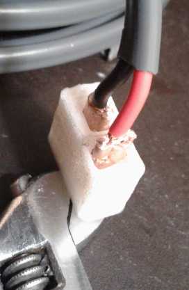
 I shaped some copper for the blades and cut two crimp
rings from the 6mm copper pipe with 1 mm thick walls. I wired and
crimped them. Things didn't fit
readily (even the screws were too tight) and I adjusted some dimensions
(yet again) so
the next one would be easier.
I shaped some copper for the blades and cut two crimp
rings from the 6mm copper pipe with 1 mm thick walls. I wired and
crimped them. Things didn't fit
readily (even the screws were too tight) and I adjusted some dimensions
(yet again) so
the next one would be easier.
Just for the sake of doing something with it I attached a
flat "COB" ("Chip on Board") LED light board through a resistor and
plugged it into 12 volts so the light came on. Now the light just needs
a housing... 3D printed... and a heatsink... NO! Get back! Not another
project.
Simple
Air
Compression
Heat
Pumping
- or -
How to Heat a Building Almost for Free
Warning: long, convoluted article
(6th) If, as the paper Coefficient of Performance of Stirling
Refrigerators had seemed to indicate, Stirling engines could get a
coefficient of performance ("COP") for heating or cooling as high as 8
or 10 at a 30°c temperature differential with simple gas expansion
and contraction, I wondered what society has overlooked that we are
still using ozone depleting, refrigerant phase change gas/liquid that
gets (as best I understand) COP under 4 or 5. Certainly house heat
pumps
are only around 3, and less in freezing weather.
Even having far more than enough projects, my mind just
couldn't let this rest. (Especially in the cold weather!) What
coefficient of performance was really
possible - and practical, by compressing and expanding air? If a
Stirling engine works doing nothing but sort of churning air inside a
closed cylinder, what was the ultimate? What COP could simple open loop
air compression and expansion give? And how simple could such systems
be made? Could they also be far more practical and economical to
install than refrigerant based systems? Could they simple enough to be
practical for hot water heaters, clothes dryers and maybe even cooking
ovens?
I began to think that if it really worked, such high COP
heat pumping could be central to answering energy problems by greatly
reducing the demand side of the equation. If one only needs (say) 1/4
as much energy to live just as well as before or better, the need for
energy supply is greatly reduced. Not only grid-tied solar panels
(supply side) but low energy light emitting diode ("LED") lighting
(demand side) has already reduced the loads on many utility power
grids. High COP heat pumping would do much more.
Heating and cooling are the greatest energy consumers in
most lives. Dwelling heating and cooling, followed by heating for hot
water are the greatest energy uses in a house.
Consider the effects if 5000 watts of dwelling heat could
be pumped in from outdoors using just 500 watts of electricity. I could
perhaps heat my whole house electrically with that - the amount of
energy now being used in one small electric heater to keep mold out of
my travel trailer. Or that trailer with 50 watts. Or heat (or cool) the
bedroom with 175 watts instead of 1750. Or run a fridge needing 300
watts of cooling from a 30 watt supply. Or in a hot water tank get
perhaps 3000 watts of heating from say 400 watts of electricity.
These things would make a tremendous difference -
a "game changing" difference! And is 10 the ultimate COP attainable?
Ground source heat pumping reduces the temperature differential, which
would further and substantially increase the COP from whatever was
being got from cold air in winter. Suddenly the potential for
drastically, and probably easily, reducing the total energy needs of a
home - and a whole society - comes into focus.
The load of a refrigerator and freezer might be thought
not very significant, but they run so much over each day that they use
enough that it's hard to keep them supplied from solar power, and most
every home has at least a fridge.
And new uses come into view as well. Perhaps it would
become practical to heat a greenhouse enough (as well as lit enough
with LED lighting) to grow things all winter? Perhaps the separate home
workshop can be properly heated to make working in it more comfortable
in the winter without incurring major expense?
A big advantage of an open air system in home heat pumping
is obvious: In closed system heat pumps, refrigerant sent to the
outdoor unit has been greatly cooled to heat the indoors, and must
be reheated back up toward the outdoor temperature before it is
recirculated. There is a big heat exchange pipe with radiator fins
in it, and a big fan blowing outside air onto it to try to heat it up
again. And it is still a bit colder than the outdoor air when it is
sent back into
the house to again extract heat from, increasing the thermal gradient
that the compressor must pump it against. And the cold refrigerant is
subject to
creating frost on the radiator fins, so it loses efficacy when the
weather get down near freezing, let alone when it is even colder. A
simple COP 1 "auxiliary" electric heater takes over in the colder
weather when heating costs the most - ouch!
The air expansion system would merely draw in outdoor air
at the temperature it is, and blow it out again, colder, somewhere
else. There is no outdoor unit needed at all, and it suffers nothing
from very cool or below freezing weather. (It gets better - read on!)
(9th) On the 6th and 7th I started writing a bunch of stuff, but I was
confused by the unfamiliar subject area abetted by a misleading
statement in Wikipedia -- in fact I edited the Wikipedia article.
A
graph indicated that a COP of about 10 at 30° 'lift'
(to create a 30° temperature rise or fall) was the theoretical
maximum. (Later I found there's a simple formula for maximum COP which
the graph was based on. (it's below)) Typical COP might be half of
that,
50% efficiency as indicated. I suspect it's likely 8 or above for the
Stirling was a
theoretical rather than a realistic figure. (Unfortunately, having
failed to copy the page or a link to it (Coefficient of Performance
of Stirling Refrigerators) I couldn't find it again except at a
site that wanted a ransom for permission to read it, so I
didn't.)
What might the simple open
loop compressed air system
really achieve? Before I got far enough to be disillusioned, I had hit
on another aspect: because it was open loop instead of closed
cycle, it could be made so that instead of heating outdoor air, the
heat pump could further heat indoor air, just a little. Theoretical COP
limit for say a 10° lift was 30, and for 15°, 20. At just
7.5° it could hit 40. Now THOSE figures left a lot of room for
actually achieving a COP of around 10 - or even higher.
The more I looked, the more I found that the whole thing
was a lot more complex than simple 'ideal gas' laws. Something that
especially struck me was "isothermal" versus "adiabatic". In an
isothermal demo a piston in a poorly insulated cylinder slowly
compresses the gas to higher pressure in a smaller volume. The gas
hardly changes temperature (eg, <1°) because the heat gain is
lost into the environment. That would demonstrate "the ideal gas law"
equation perfectly - and shows why it is misleading. But the gas DID
gain heat - it merely wasn't retained! In an adiabatic demo, a piston
in a well insulated cylinder (a "fire syringe") is suddenly plunged
(hammered) down, compressing the gas so fast and with so little heat
loss that the air temperature obtained and retained for a moment can
ignite cotton in the cylinder.
[Now back to the 6th, re-edited on 9th to correct for Wikipedia error
and other misconceptions... The reader could probably skip or
skim quite a lot of the following without missing much - especially if
familiar with the subject.]
(6th) Now, what about trying to make it work? I looked up Boyle's Law
which I had heard of and ended up at the ideal gas law:
P * V = n * R * T
where:
P = pressure in Pascals
V = volume in cubic meters
n = is the number of moles of the gas
R = 8.314 Joules/(°K*n)
T = Temperature in degrees Kelvin
There was nothing in that to suggest that when the pressure is doubled,
the temperature will double too, because if a cylinder is compressed to
double, obviously the amount of gas "n" will also double and the two
sides will cancel with temperature "T" remaining the same.
Then there was the combined gas law, which doesn't specify the number
of moles but shows relationships:
P * V
------ = k
T
Where k = an arbitrary constant, and the others are as above. (This was
stated in a mistaken or at least misleading form on Wikipedia, saying
"'k' is a constant (for a given amount of gas)". [My italics]
This caused me to double "k" when I doubled pressure, since there was
now twice as much gas. That fit with what the "ideal gas law" said.
Then temperature would remain the same no matter how much the gas was
compressed or rarified. How then did one change the temperature of a
gas by heat pumping? One could change the pressure by changing the
temperature, but not the temperature by changing the pressure? It made
no sense and caused me further confusion.
Finally I realized that the temperature simply must double
if the pressure is doubled regardless of what the formulas seemed to
say, and if the gas is doubled the pressure must
double. "k" can NOT describe the amount of gas. (It's not very often I
see need to edit Wikipedia, but I removed those words. I also rewrote
several equations & text below.)
Solving for "T", replace all values with "1" in arbitrary units.
1(P) * 1(V)
------------- = 1(T)
1(k)
If we compress air into a fixed size tank until the pressure is
doubled, the temperature is doubled.
2(P) * 1(V)
------------- = 2(T)
1(k)
Of course the gas soon heats the pressure vessel walls and
cools, and the pressure vessel walls eventually cool to ambient. Then
if we open a valve and let out the extra air, the pressure is halved
(back to "1" again) and "k" is halved:
.5(P) * 1(V)
T = -------------- = .5 (half temperature)
1(k)
Since the solid pressure vessel quickly absorbs the temperature
of the gas and since it is far more massive than the air, the actual
temperature rise and fall are only a little. Thus to attain significant
heating or cooling the process must be (a) far higher pressures, (b)
incrementally repetitive or (c) continuous. Or of course a combination
of these.
 Then I thought
that compressed gas hissing out
through a valve would rapidly cool. It was said that it doesn't. Again
this appeared to be misinformation, but the cooling isn't really
perceptible because the decompressing air is so quickly dispersed into
the surrounding air. But I got a good cooling result from air hissing
out through
the water drain spigot. Why? I could feel moisture there when I did
that test. The water was vaporizing into the thinning, moving air,
causing evaporative cooling.
Then I thought
that compressed gas hissing out
through a valve would rapidly cool. It was said that it doesn't. Again
this appeared to be misinformation, but the cooling isn't really
perceptible because the decompressing air is so quickly dispersed into
the surrounding air. But I got a good cooling result from air hissing
out through
the water drain spigot. Why? I could feel moisture there when I did
that test. The water was vaporizing into the thinning, moving air,
causing evaporative cooling.
Cooling
Maybe the project should be separated into its two halves:
the compression of the air and the decompression. I could use the air
compressor to fill a tank with compressed air, then consider just the
cooling half of the cycle, the refrigeration.
What about taking a compressed air tank and feeding that
compressed air through a thin pipe that runs through a fridge? It might
hiss through a narrow valve into the pipe (both inside the fridge), and
then the coldness would radiate through the pipe walls.
For using air compression and decompression, which as seen
in the Stirling heat pumping figures can give a very high COP, would
completely decompressing the compressed air within the fridge not give
the ultimate cooling COP? The expanding air should continuously cool
the pipe with the utmost efficacy possible from compressed air, however
efficiently or inefficiently it was compressed, right? Proving (or
disproving) that should be an easy experiment!
Then the overall COP would be directly proportional to the
efficiency with which the compressor compressed the air. And with
"ultimate" COP on the cooling side, if a Stirling engine could manage a
COP of 8 or 10, it should be possible to attain an even higher COP. Is
there anything wrong with this picture?
That reminded me of the Tata Motors compressed air vans:
they have free air conditioning from the cooling of the expanding air
coming out of the engine cylinders. Great thing for hot climes, I'm
sure! Of course, they are unconcerned with the COP because the main
purpose of the compressed air is to move the vehicle. (It was well over
100 Km range from a carbon fiber compressed air tank under the van
(that would rip, not explode); I don't remember - Was it even 200 or
300 Km? Wow!)
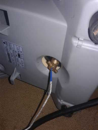
If the "hissing valve" released depressurized cold air
into the pipe, a length of pipe could radiate that coldness into the
fridge. I looked for and found three 1/2 inch copper pipes with
aluminum fins that I made some years back in connection with peltier
modules and low pressure boiling water heat transfer. (I was amazed I
found them all quickly and easily in the first 3 different places I
looked - they had been carelessly tossed here and there when I moved.)
I also had a 120(?) liter brass water tank. (Had it for
almost 40 years, originally intending to make a solar hot water system
that would last.) Surely it would take at least 60 pounds of pressure.
Refrigeration shouldn't need 1/2 that much, and such a large tank would
probably run a fridge for many hours before refilling it.
Let's see, how much pressure would it take?: If we want (eg) 40°c
cooling for a freezer (from +20 to -20 or in real scale terms from
293° to 253°K) we have to have at least that much gas
expansion, so we have to compress it that much.
293 / 253 = "x" PSI / 14.7 PSI
or
x = (293/253) * 14.7 = 17.0 PSI
So we need at least 2.3 PSI (above regular atmospheric pressure) to get
40° cooling.
Gosh, that seems like nothing! It doesn't take
much to compress air that much. Of course it'll need to be considerably
higher than that (or an awful lot of actual air) to cool a real freezer
with finite insulation, but the potential for very high COP seems to be
there.
(7th) Can everyone really have missed something this simple
that sounds this good for this long? I can't believe I'm the first to
come up with it. One thing I could potentially believe is it just isn't
as good in real life as it sounds before calculating or testing it out
- but not without trying it out! Another is that someone invented it
and patented it long ago, and a company making 'conventional'
refrigerators bought the patent and threw it in a drawer, just like the
car companies have always done with better car inventions. Since
someone held the patent, no one was able to build them and eventually
the whole technology was forgotten. Western civilization is replete
with examples of this practice.
I didn't see how to easily calculate exactly what to
expect in advance, but checking it out just looked easier and easier...
I could connect the three 1/2 inch copper radiator pipes
together in series and to a valve, and mount the assembly to the
underside of the lid of the shallow chest fridge, with an inlet and an
outlet to the outside air.
Then I could just connect the air compressor to the fridge
inlet pipe, and set its output to (say) 10 PSI.
Initial testing would be a matter of cracking open the
valve until air was hissing through it and seeing how fast the fridge
got cold and what temperature it got down to, and connecting a power
monitor to see how much power the air compressor used.
To get the roughest of ideas:
1. My fridge-freezer is around 150 watts and runs 60%(?) of the time.
Call that 2.16 KWH/day. (Well, less in winter when the kitchen is
cold.) I should monitor that and record it, too.
2. My shallow chest fridge is maybe 1/3 the size and has no freezer.
Energy parity then might be around .5 KWH/day. If over some days it
used substantially less than that, it would doubtless be owing to a
higher COP. If it was around parity, it might be compressor
inefficiency compensated for by higher COP, or it might be just similar
COP.
It all depends how far open the valve has to be cracked to
get the requisite cooling to keep the small fridge cold. That air flow
will determine how often the compressor has to come on. And that will
determine how much energy is used. An important point is that the
compressor runs until it hits 120 PSI or so. If it only hit (eg) 20 and
shut off, it might run more efficiently and use a lot less energy, even
while running much more often to supply the same amount of air overall.
Air compressors are probably not designed to maximize efficiency in the
first place. People are simply happy if they work. (Perhaps at some
point I could try opening the control box and adjusting it to have it
shut off at a much lower pressure?)
If it proves worthwhile, the next step would be
thermostatic control. This could be on-off, or analog with an air valve
that can be minutely adjusted to pass more or less air, depending on
the temperature and heat loading. Then one has a real fridge or
freezer. (In the 1980s doing computerized controls for Victoria schools
I had an electrically activated variable pneumatic valve. Where did I
get it? Accutemp? Are they still available?)
There would be a second advantage to such a fridge: The
compressor could be somewhere else besides in or at the fridge,
connected by a single pipe. It could be in the basement underneath. And
it would only run occasionally. Kitchens - and many cafes - could be
quiet places again!
By evening of the 7th I had convinced myself that this
project was more worth pursuing than the woodstove electricity
generator. Furthermore, the first experiments with the fridge were so
simple to set up (given that I had an air compressor and most of the
parts) it seemed foolish not to do so.
Heat Pump Heating
But what about the heating side of the equation? Soon this
replaced cooling in my thoughts because a fantastic potential came into
view. Logic said that if a Stirling engine could manage COP up to 10,
that unless the compressor was very inefficient, the heat being put
into the air tank - the thermal energy of the air going into the tank -
must be much greater than the amount of electricity it took to pump it
in. In the tank was the thermal energy to heat a house, if radiated out
through pipes and probably with a fan. Once the heat radiates out along
the air pipe, it is routed outside the house and decompressed at a
spigot to cool the great outdoors. More air has to be compressed from
the inlet side to keep pressure in the pipe and pumping in thermal
energy from outdoors. Once again the pressure doesn't have to be very
high to gain a 30, 40 or 50 degree differential from the outside air to
the radiator pipe.
I had no idea how efficient or inefficient my compressor
was. It was 99 $ at Rona with a plethora of attachments. It's a light
duty unit intended to be used once in a while to blow off dust or pump
up a car tire. Okay for limited testing, but not much more.
For house heating one would want a unit designed for
continuous service in a building, and optimized for efficiency. and as
quiet as they come. And it needs to move air volume, but not with a
high pressure buildup. But! such units are doubtless already available.
I started off thinking that if it became a project, I would have to
build some pumping unit from scratch, but (excluding controls) really
there are only three components: compressor, radiaators and
decompressor valve. Only the compressor is complex and uses power.
Unlike with
most new inventions, I wouldn't need to build/create any major
component, to create a new type of high COP open air home heat pump
system! This makes it an incredibly tempting project for someone much
too busy to start yet another new project.
Some Simple Tests
(8th) I brought the air compressor into the livingroom. (At -2°c
outside that was the only place warm enough to work in - and by no
means warm as the stove had gone out in the early AM, and once out it
is hard to get a good fire going in it again.) I plugged it in and
turned it on. I connected the hose with the dust blower attachment. I
stuck a plastic tube over the blower end and inserted a thermocouple
into the tube. It was about 15°. I pressed the lever lightly and
air started hissing out into the tube. But instead of dropping the
temperature rose to 18°.
This was a puzzle. Why didn't it drop? How warm was the
air in the tank in the compressor? I had brought it in from the
unheated workshop and it was about freezing outside. I cursed that
there was a plastic enclosure over the whole compressor. (I liked it
until now!) I unscrewed some screws and took the top off. The
thermistor
said the tank was about 18°.
So on the compression side of the equation, filling the
tank with compressed air had probably raised it from around 0 degrees
to 18? That seemed like a lot. How long had the compressor run - a
minute? But then, the livingroom air was 15° and most of the actual
air it was filled with came from indoors. So more like 14(?) to 18.
Subsequent releases and refillings with air showed that it rose almost
1° with each 15 second refilling burst. After a few tests it was up
to 23. It used about 780 watts whenever it was running: .004167 hours *
780 W = 3.25 watt-hours to raise the tank almost a degree. (I was
surprised the compressor used so much power. That's half of what's
allowed in a regular 120 V plug-in for what I thought of as a pretty
minimal compressor.)
Next I tried tipping the compressor sideways and I stuck
the thermocouple in the hole in the water drain spigot. I turned that
on and the temperature dropped with the hissing air, this time as
expected. Depending on how far it was opened and how fast the air was
hissing out, it dropped down as low as 4°c. And this of course also
cooled the brass spigot as well, probably to about the air temperature,
which would also cool the tank wall in the area. When the tank was
empty (or at least lower pressure) I checked it and found the tank
itself had dropped a few degrees with the decreasing air pressure. (At
least, in the area near the spigot - I had closed the case again and
that was the only accessible surface of the tank.)
3.25 watt-hours is about the amount of heat from running a
20 watt soldering iron inside it for 9.75 minutes. Would that do it, or
were we getting a COP of over 1?
Now I cursed that the thermocouple temperature reading was
unit degrees only. Still, if I put the soldering iron in for 30
minutes, it should be 3°. And the wires pulling on the compressor's
flimsy push-button power switch broke it, in preference to pulling the
slip-on connectors off the switch. I tried to fix it, but now it only
worked while I held it on.
I found a 25 watt iron that the hot end fit in the hole.
In about 8-9 minutes it raised the air temperature in the tank by about
5°. (It said 6 near the upper side and 4 near the lower. So how
much had the tank walls heated?) I certainly hadn't proved anything
good there! But the conditions of the tests and measurements, and the
seemingly low efficiency of the compressor, were such that I thought I
hadn't disproved much, either. (From store product pages it seemed
compressors of no more than twice the power probably moved as much as
ten times as much air. Again just a guess since I don't have the specs
for my own.)
Then I took off the spigot and connected the air hose to
its hole in the tank, as the threads were the same. Then I tried again
to have the air hiss out through the dust blower, this time direct from
the tank, and blowing into a copper pipe. But once again the
temperature seemed about the same as the tank. With the thermocouple
stuck
right into the dust blower opening and no pipe, the temperature dropped
only slightly. Either the dust blower or the long hose was causing some
sort of trouble, while the drain spigot worked great. I couldn't try
the spigot with the hose or the blower without it owing ending up with
M to M or F to F threaded holes. I did try the spigot on a different
short
hose. Again the temperature didn't change much. It dropped a few
degrees if I opened it wide enough, but nothing like when connected
straight onto the tank. This still seemed like a puzzle to me.
I put the spigot back on the bottom of the tank and tried
again. Good temperature drop. The more the airflow, the more the drop
as before but I didn't get it below 9°. I held a 3/8" copper pipe
against it and put the thermocouple inside the pipe. I didn't see such
large temperature drops (12°), but the air blowing out the end was
cold.
I decided that was about all I could do without connecting
up the radiator pipes. That meant buying fittings and I still had a bad
cold. But I got on line and looked for a better air compressor. It
seemed that in addition to noisy piston compressors there were rotary
screw, scroll and centrifugal compressors. But they were all big and
costly. Piston was the only realistic option.
Little compressors such as mine are under .5 cubic feet
per minute (CFM) capacity. I ordered a bigger one at KMS Tools, a 1.5
HP Makita (it claimed 2 HP but the voltage and current figures said
that was a lie) and 4.1 CFM capacity at 90 PSI. It was also 79 dB of
noise and 77 pounds shipping - too big for the post office. Second best
seemed to be a cheaper one from Princess Auto, but it used a little
more power and added 5 dB to get about the same airflow. The idea here
was to use the least power to get highest COP, whatever it
would be.
I also came up with the idea to have the air intake inside
the house instead of outside. Then the unit would be adding heat to the
indoor temperature instead of the outdoor. That would surely make for
highest COP! But the cooling (decompressing) air would vent to the
outside. The trick then would be to use a heat exchanger so that as the
house sucked in air, that air would automatically be warmed to indoor
temperature. Unfortunately there seems to be a flaw in there: If the
expanding/cooling air is venting to the outside, the house will be
sucking in through the heat exchanger but not blowing out. That won't
work. I must think about that one!
(9th) Okay, I have it! The air in the pipes is warmer as long as it is
compressed, but it is losing heat as it radiates it into the house
until it is house temperature. Instead of discharging the compressed
air outside somewhere else away from the intake, the compressed air
pipes would extend through, would be, the cooling side of the heat
exchanger. Only
after they exit that would the air be allowed to decompress and cool
from gas expansion. This will of course require some quite different
type of heat exchanger from the usual diagonal coroplast sheets, since
those can't be expected to hold compressed air (or even be made not to
leak it out).
But once we have that configured, there is tremendous
potential for ultimate COP. The air to the compressor is warmed coming
through the heat exchanger almost to indoor temperature. Thus it is
compressing room temperature air to an even warmer level, not outdoor
temperature air. This means it doesn't have to pump across much "lift",
much temperature rise. If the radiators were 40°c and the house
23°, it's only 17°, regardless of the outdoor temperature.
And
that
would
be
for
passive
pipe
radiators.
With
forced
air
the
radiators
might be 35° (or less) and so the difference would be
just 12.
when the air has gone through the radiators to the exit, it should be
almost down to room temperature. From there it goes through the exit
side of the heat exchanger, losing heat presumably almost to outdoor
temperature as it heats the incoming air from outdoor to almost house
temperature. Only then is it decompressed, hissing out a valve, and
discharged pointing away from the air
intake. Thus owing to having the open air system instead of a closed
loop we can gain the following benefits (here we will ignore incidental
losses, the "almosts" and "nearlys"):
* The air is heated from outdoor to indoor temperature as it enters the
house through the heat exchanger.
* The compressor compresses and heats this room temperature air instead
of cold outdoor air,
giving it a very low lift with very high COP.
Colder weather increases heating load, but it doesn't affect the COP.
* The flowing air heat radiator pipes inside the house (with or without
forced air blowing over them) are nothing special:
they impart the heat of the compressed air into the
dwelling.
* The spent heating air in the radiator pipes, now only at house
temperature, goes through the heat exchanger,
warming the air to the compressor from outdoor
to indoor temperature and itself cooling to outdoor temperature.
* This cold air is then exhausted through an appropriate size
slit/valve exit, aimed away from the intake.
Up to this exit point, all the air piping is at the
pressure of the compressed air tank.
* The compressor doesn't have to be directly connected to the incoming
heat
exchanger air:
The air being 'consumed' by the compressor and then
going out will create a vacuum that will cause fresh
air to come in through the heat exchanger. Thus
instead of having a stuffy house to keep the cold out,
ample free ventilation with fresh outdoor air,
preheated to room temperature, is obtained.
* The machine heat from inefficiencies in the compressor is added to
the indoor temperature too.
As I see it, the chief downside - and it's a big one - is
having a noisy air compressor running somewhere in the house. (That's
why I was investigating quieter other-than-piston compressor types.) If
noise can be kept from being a show stopper, this project and its
potential to heat buildings almost for free just looks more and more
exciting!
For cooling a building, one would want reverse the heat
exchanger and have the compressor outside - a much more appealing
configuration but not of much use where I live.
-----
On the 9th I also finally found the actual theoretical parameter of
heat pumping, the formula for "ideal COP":
Thot
Cop[ideal] = ---------- (temperatures T-hot and T-cold of course
must be in
°K)
Thot - Tcold
So for say a 30 degree 'lift' from 270°K (-3°C) to 300°K
(27°C), we would get:
300
---- = 10
30
Sure enough, just what the graph indicated!
And then if we can reduce that by heating indoor temperature air by
just 10° from (eg) 290 to 300, we get:
300
---- = 30
10
Even at 40% efficiency that's actual COP=12 - huge! That's 82 watts
electricity to get 1000 watts of heat!
(11th) And if with sufficient radiator pipes and fans we got the
differential down to 5°, ideal COP would be 60 and 'actual' target
of about 25: 40 watts to make 1000 watts of heat.
Since air compressors themselves are more like 1500 watts
than 25, one gets the idea they won't have to run a high percentage of
the time to keep the radiators filled with moving compressed air, and
the house warm.
One may ask, "But where does the inevitable cooling occur
that goes along with the heating in heat pump systems?"
Here again is where the open loop system is so different
from the usual closed loop. When air is compressed into the air
compressor tank, it is taken from the house. Rarifying the house air
would cause cooling. What will actually happen is that air will leak or
flow into the house to prevent any notable vacuum from developing. And
the amount of air taken from Earth's atmosphere is to say the least
negligible. Therefore the cooling of bringing in the air to compress is
negligible.
Of course if one is heating the house because it's cold
out, the air coming into the house would be cold air. That's where the
heat exchanger comes into play. Over a sufficient length of dual
entry-exit duct, the temperature if the incoming air is gradually
raised to near room temperature by conduction with that going out,
while the exhausting air is gradually lowered to near outdoor
temperatures by the air going the opposite direction in the contacting
pipe.
For a bit I thought I here was an 'invention' where I
wouldn't have to make anything special. But the outgoing air from the
radiator pipes must be kept compressed until it is through the heat
exchanger, so radiator pipes with fins inside an outer duct must
replace the usual 32 diagonally alternately arranged one foot by one
foot squares of coroplast. Since the compressor will be drawing the air
into the house, and then the compressed air will be released outside
after passing through it, it can be a simple passive unit.
If the compressor can move 4 cubic feet of air per minute,
what does the capacity of the heat exchanger need to be? I don't know,
but I have a feeling it'll be pretty large.
Still, the whole thing seems so simple as to be worthwhile
trying out for the rest of this winter, this heating season. My
next electricity bill is looking like 250$. Even with the woodstove the
majority is for heat - the trailer to prevent mold (85$ for 2 months),
and the bedroom at at night (similar?). A few more finned
radiator pipes and the heat exchanger, and the air compressor I'm
ordering, should be mostly all I need. That and an immensely sound
insulating box. (Now I need some thin aluminum
sheet, perhaps #20-24 gauge, to make more pipe radiator fins. I don't
have it, and I don't know where to buy it on this island. Mail order
from ??? To heat from a low temperature will take a lot of radiator
pipe. Or, surely someone somewhere sells finned radiator pipe?)
(12th) I looked it up on line, and I became convinced that making my
own was not a good way to go. There were machines winding spiral fins
onto pipes that had several fins per inch instead of just two, and they
probably made better contact with the pipe. And there were heat
exchanger assemblies of pipes that might be just about what I needed,
too. But I had a hunch that such things would be costly, as well as not
available locally. Then it occurred to me that I might try the refuse
transfer station and or the landfill. Perhaps someone might have thrown
away some suitable pipes or heat exchangers that hadn't been mashed up
yet? It was worth trying.
On the 13th I visited Mike, and noticed a piece of dryer
duct hose on the floor of his shop. Hmm... I went to the hardware store
and found some with an aluminized skin. I bought a piece. My finned
tubes just fit inside. That was it: indoor heat exchanger! The
pressurized warm air would be in the finned pipes, and air would blow
through this outer duct. That would pick up the heat best in the least
amount of finned pipe and blow it out to the house.
Then I decided I probably couldn't afford the nice finned
pipes I really wanted, and (not expecting to find much at the dump) I
asked one company if they could supply me with 2000 square aluminum
fins made to push onto regular copper plumbing pipes that I already
had. I got no reply and on the 15th I asked a neighbour if he knew
where I might get sheet aluminum. He said there was nowhere on the
island, but another neighbour often ordered it from a place in Prince
Rupert. I phoned that one and got a name and phone number. I asked for
two 4 foot by 8 foot sheets. That could make 1600 fins. Then I called
back and said "pure aluminum if you can get it." Pure aluminum is a
substantially better conductor of heat and electricity than any alloy.
I found a site that said it was "238" where most alloys were "160" or
less,
tho a couple were "190". (Pure aluminum is 4th best; gold is better,
copper is 2nd best, and silver is a few percent better than copper,
which was "420". I didn't note what the units were. Although it would
be ideal, I'm
not buying silver - or even copper for that matter - just for fins!) I
got no return call from the store, either.
Copper Pipe, Soldered Copper Fins
(19th) I changed my mind. I already had lots of copper pipes, both
scrapyard and new from a plumbing wholesaler. Not only is it better
heat transfer through the metal, but pieces of copper can be soldered
to the outside of copper pipes - a better thermal connection than
friction-fit aluminum fins. For no evident reason I just felt a
powerful urge to buy all this copper pipe about 5 years ago and I spent
some time collecting it. Now I realized it'd be the best for this
project, and I wouldn't be able to buy them at a reasonable price on
this island. What luck that I had them! "All things work together for
the progress of men and angels" - the Urantia Book
So I decided to cut up scrap pipes to make solder-on fins
for new pipes. Perhaps I would run them through the jewelers rolling
mill and stretch them longer and thinner? They'd go farther that way. I
was also wondering about airflow. If the pipes were inside dryer duct
and the fins were crossways like my aluminum fins, would air flowing
along the pipe really get in there? But if they were longitudinal,
would the air again flow alongside with much less heat transfer? I
decided I would solder them on diagonally. That should optimally
capture air passing by making maximum turbulence, without blocking the
flow.
The better the heat transfer, the shorter the pipes and
ducts could be. or the higher the COP.
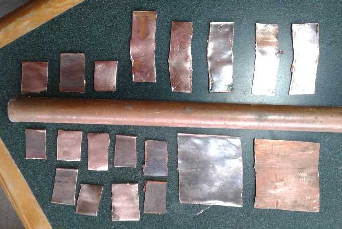 I first slit a
piece of pipe and then cut it off with a
hacksaw. It was about 1-3/4" square. That was slow. I found the only
practical way to cut off the pipe pieces was with the angle grinder,
and I also used it to slit them. But after a while I found I could slit
them with tinsnips. Next I cut some only ~3/4" long (x ~1-3/4"). I
could 'unroll' these with two pairs of pliers instead of prying them
open with successively larger wedges. Then I decided 1-3/4" long was
too long anyway and started cutting them in half, ending up with
varying sizes really averaging around 5/8" x 7/8". I realized the
copper was tempered, so to roll it thinner I'd have to heat it red hot
and let
it cool. I didn't bother. They seemed like a good thickness anyway.
I first slit a
piece of pipe and then cut it off with a
hacksaw. It was about 1-3/4" square. That was slow. I found the only
practical way to cut off the pipe pieces was with the angle grinder,
and I also used it to slit them. But after a while I found I could slit
them with tinsnips. Next I cut some only ~3/4" long (x ~1-3/4"). I
could 'unroll' these with two pairs of pliers instead of prying them
open with successively larger wedges. Then I decided 1-3/4" long was
too long anyway and started cutting them in half, ending up with
varying sizes really averaging around 5/8" x 7/8". I realized the
copper was tempered, so to roll it thinner I'd have to heat it red hot
and let
it cool. I didn't bother. They seemed like a good thickness anyway.
I was worried about trying to solder them to the pipe. If
I used a torch it would melt solder out to the ones already done and
they would fall off. The soldering iron couldn't heat that much copper.
I but I ended up turning it up to 750°(F - from 550°) and using
it. At that temperature it could quickly melt solder in the immediate
area of the join without the heat spreading too far and before it
itself cooled below soldering temperature. (It didn't always bond well.
I had to wait sometimes for the iron to heat back up between tries.
Luckily the temperature is shown on its display.)
Between that technique and
soldering flat edges onto round
pipe, the joins weren't the strongest, but they would transfer heat to
the fins. At first I put them sticking straight out. Then I got more
creative and started trying various angles, which put more fin surface
in contact with the solder and pipe, while still trying to have them
diagonal to the air flow.
After working at it quite a while, I had 15" of
"stegosaurus pipe" and another 30 fins to stick on. How much pipe did I
need? Maybe 10 meters? (20th) In a short morning session I had put on
the rest of these fins and extended it to 24". Just 8% done! And I had
got pretty good at it, so barring finding some way to speed it up or
automate it, it was going to be tedious.
The slowest parts were cleaning off the copper (with a
wire brush on the grinder and stationary belt sander) and soldering
them on. I could speed up the cleaning by using only the 'new' pipes. I
probably had enough. It seemed like a waste cutting them up into bits
when I had the old ones, but I wanted to get on with it. (Of course,
having flat copper sheet metal to start with, cleaning it as one piece
and then cutting it up with a sheet metal shear would be far simpler.)
I didn't see how to speed up the soldering. Perhaps some
pencil flame to melt the solder rapidly, with a jig to hold the pipe
and fin(s) aligned? Was that worth doing for one heater? 25 feet of
stegosaurus pipe... hmm! Well, I had 5 feet of the old aluminum finned
pipe, too. Should I use that? Then "only" 20 feet - 18 more - to cut
and solder up.
Let's see... a jig. Say 3 feet long. It would hold each
end of the pipe in place. A thing with a diagonal slot in it every two
inches would be directly above along the whole length. The fins would
slip through the slots and sit vertical on top of the pipe even without
solder or if the solder was melted. Then one could run a propane torch
and solder along the pipe from one end to the other and solder the 3
feet of fins on in one operation. Then the pipe could be rotated
90° and the process repeated for all four 'quadrants'. (Uh-oh! How
do we prevent the side and bottom fins from coming un-soldered? Aha!
Fill the pipe half full of water and plug the ends! Then the solder can
only melt on the top of the pipe. Or set the pipe in a tray of water
half way up the sides - that would wet the bottom and side fins, too.)
If one could figure out how to make the diagonal slots,
perhaps in a piece of wood - or aluminum - that would sure speed up the
soldering. Perhaps it would have to be made in two pieces with one edge
of each shaped so that when put together they would form the slots.
A Test
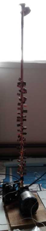 Since I had
the little vacuum-pressure pump (75 watts),
and a few finned radiators, I realized I could run a test if I just
found a few pipe fittings (new and old) and a pressure gauge (kicking
around for years - I'd never used it before. What luck I still had it!)
and did some soldering to get things to fit together. I mounted the
pump on a piece of plywood. (I also cut some more pieces to make it
into a box.) With a compression fitting I attached the stegosaur pipe
to its air outlet, pointing straight up. On the top end of that I put a
90° elbow with a 1/2 inch "National Pipe Thread" (NPT) female
threaded output, to which various things could be easily attached and
removed.
Since I had
the little vacuum-pressure pump (75 watts),
and a few finned radiators, I realized I could run a test if I just
found a few pipe fittings (new and old) and a pressure gauge (kicking
around for years - I'd never used it before. What luck I still had it!)
and did some soldering to get things to fit together. I mounted the
pump on a piece of plywood. (I also cut some more pieces to make it
into a box.) With a compression fitting I attached the stegosaur pipe
to its air outlet, pointing straight up. On the top end of that I put a
90° elbow with a 1/2 inch "National Pipe Thread" (NPT) female
threaded output, to which various things could be easily attached and
removed.
First I tried a garden hose faucet. It leaked through the handle when
it was opened and the pressure gauge (it had a garden hose fitting)
didn't read. I took the garden hose piece off the pressure gauge, which
left it with its original 1/4 inch NPT. Using two fittings and a pipe
between I made up an adapter to fit the gauge onto the 1/2" NPT threads.
So I had the compressor, the finned pipe sticking up, and
a gauge on the top end. To allow air to flow, I had to partly unscrew
the gauge. (That would have worked better if it didn't start rattling
and turning by itself with the compressor vibration, but it sufficed.)
I taped a temperature sensor to the pipe just above the compressor. (I
wished I had a better one - this one was a big blob that only changed
its reading very slowly.)
But when I noticed it, I wasn't impressed with the tiny
holes in the outlet pipe opening of the pump. It seemed to me that with
air flowing, pressure might drop significantly between the
piston/cylinder and the pipe owing to the resistance. It might not be a
very good pump for this purpose.
At the start the temperature was 18.7°. With the gauge
tightened the pressure went up to about 25 PSI. Having no shutoff the
pump kept pumping but the pressure didn't go up further. I loosened the
gauge off to allow air to flow. The temperature gradually started to
rise. I didn't think to time it because I wasn't sure what to expect.
In maybe 15 minutes it climbed to 29.0° and then pretty much stayed
there. It seemed to climb fastest with lower pressures and higher air
flows. But the heat didn't extend very far up the pipe. The upper end
felt cool throughout. (I really needed 3 or 4 temperature sensors.) I
couldn't tell whether the temperature rise was owing to the heat
pumping effect, or was just heat from the motor and pump itself.
presumably much of the 75 watts was turning the motor and pump rather
than making heat, and the air was moving through, so the temperature
rise might indicate that there was more heat entering the pipe than
just from electrical and mechanical inefficiencies in the pump. But it
was disappointing that only the lower section, perhaps the bottom 10
inches, of the pipe warmed up noticeably above room temperature.
More Compressed Air Piping and Test 2
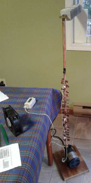 Of course
since the air was venting and decompressing
indoors, there would have been no net heat pumping. For that it would
have to vent outdoors. I decided to try that. I put together some more
fittings and did some more soldering, and added a horizontal pipe with
aluminum fins, one of my old ones. I put that out a window (opened it
2mm) and put the pressure meter on the end, outside the window. Again
it seemed to work best at around 10 PSI, as best I could tell, which
wasn't very well. I could hear air hissing through, especially where
the bend was.
Of course
since the air was venting and decompressing
indoors, there would have been no net heat pumping. For that it would
have to vent outdoors. I decided to try that. I put together some more
fittings and did some more soldering, and added a horizontal pipe with
aluminum fins, one of my old ones. I put that out a window (opened it
2mm) and put the pressure meter on the end, outside the window. Again
it seemed to work best at around 10 PSI, as best I could tell, which
wasn't very well. I could hear air hissing through, especially where
the bend was.
After 1/2 an hour I took temperature readings, one at a
time. It was painfully slow because the temperature sensor took a
painfully long time to move and settle in. It was the only one I had
that would give .1° increments instead of just clunky unit °C
readings. I worked from the top to the bottom of the stegosaur tube. By
then headed for 1/2 an hour had gone by. Then I did it again (right
column) and got slightly different results. I couldn't measure the air
temperature itself. These were the temperatures of the outside of the
pipe or a fin right next to the pipe, in degrees C:
17.2 16.6 Room temperature (Kitchen
was cooler than livingroom)
18.2 20.0 At top
of fins
19.3
2/3
up
toward
top
of
fins
20.9 1/2 up fins
21.6
1/3
of
the
way
up
the
fins
23.2 1/4 of the way up
24.5
Near
bottom
fins
27.0
Very
bottom
fins
34.6
Fitting
on
pump.
Conclusions 2:
* First, it didn't seem like a lot of heat. 75 watts is expected to
pump 750+ watts of heat. This didn't feel like anything like that much
heat. More like 75 watts.
* From the bottom two measurements, the heat conduction from the pump
into the pipe must be poor. Perhaps there is an immediate pressure drop
from the cylinder to the output of the pump. I suspect there's a very
severe drop in efficiency at this point. (Probable, and from the tiny
openings in the pump output.)
* From 16.6° (room) to 34.6° (pump) is 18°. If it counts,
that is about double the "lift" we are hoping for, much reducing the
potential COP. And I didn't measure the body of the pump itself - it
might be even worse. (Is the teflon tape on the pump-to-pipe-fitting
join a thermal barrier?)
* Most of the apparent warmth was radiated off in the bottom section of
the pipe, notwithstanding the significant air flow through the pipe and
the weaker passive radiation. There wasn't much heat to be felt toward
the top of the fins - but they were still warmer than the room.
If I was going to continue (with this apparently low
efficiency pump), the next thing to try would be to box the unit up and
add the outer heat exchanger tube around the radiator pipe with a fan
to forcibly blow the heat out from the compressor and the pipe. That
might improve the overall performance.
(24th) Outer Ducting and Test 3:
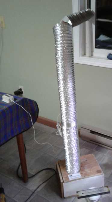 I made and assembled the
rest of the box. I found a fan labelled "48
volts" and mounted it on one end blowing into the box. I made a long
cable to plug it into a 36 volt HAT socket. It blew plenty of air and
made lots of noise at that voltage. The solar meter said it was using
3.3 watts. (Half audio output, I'm sure - but almost nothing compared
to the compressor.) The "stegosaur" finned pipe now fit inside the
dryer hose, and the air from the fan ended up blowing air out the top
hole of the dryer hose. Thus there was forced air blowing around the
pump and along the finned pipe. I couldn't attach the temperature
sensor to the inside pipe, so I just lowered it down the dryer hose. I
turned it on and let it run a while to stabilize.
I made and assembled the
rest of the box. I found a fan labelled "48
volts" and mounted it on one end blowing into the box. I made a long
cable to plug it into a 36 volt HAT socket. It blew plenty of air and
made lots of noise at that voltage. The solar meter said it was using
3.3 watts. (Half audio output, I'm sure - but almost nothing compared
to the compressor.) The "stegosaur" finned pipe now fit inside the
dryer hose, and the air from the fan ended up blowing air out the top
hole of the dryer hose. Thus there was forced air blowing around the
pump and along the finned pipe. I couldn't attach the temperature
sensor to the inside pipe, so I just lowered it down the dryer hose. I
turned it on and let it run a while to stabilize.
The air pressure was about 14 PSI. I got these temperature readings:
Room near floor where the air was being drawn in from: 17.1°.
Inside tube near bottom, just above the box: 20.1°.
Inside tube a few inches below the top opening: 19.6°.
The room air temperature at the height of the output of the unit was
about 18.3.
On opening the box I and feeling the pump and the bottom of the pipe, I
had the impression they were a little cooler than in test 2. However, I
had removed the fan to reach in, and that fact armd them up, so this
proved difficult to measure.
---
Instead of shutting it off I reduced the air pressure in
the pipe to 8 PSI and took some more measurements.
Air entering at fan (at floor level): 16.2°
Air at top of duct below exit: 18.8°
Top of box just below bottom of duct: 19.6°
I finally unplugged the compressor but left the fan running. I thought
the temperature at the bottom of the duct would drop quickly, but it
took a couple of minutes to register even .1° down. Then it started
falling, but I was surprised it took several minutes. The pump motor
body must have stored substantial heat. When it was down to 18.0 I
unplugged the fan. After that the temperature went up and after a few
more minutes passed 20° - the warmth of the motor was no longer
being blown out the top of the box.
Conclusions 3:
* The unit was blowing a considerable amount of air out the hose at
2.5-2.6° warmer than it was going in by the floor, and 1.3°
warmer than the room air around the exit. On the face of it, this seems
promising.
* So it had to be heating, and I'm guessing the performance was
substantially better than test 2 and more than just the 75 watts of the
pump. Unfortunately the way I had put the box et al together, I
couldn't measure the temperature of the pump body or the actual copper
tube temperature. One expects that with the air blowing by them, they
would be kept cooler than they were in test 2.
* With the pump sucking in room air and blowing its exhaust through the
pipe out the window, cold air was being pulled in through the window to
replace it, largely preventing the room from warming up. (In fact it
was probably drawing in far more than the pump was using. It was
definitely a considerable cold draft.)
* After couple of hours my ears were ringing and I finally put on
hearing protectors. With this little pump. Compressor noise will
definitely be an issue.
It would seem that to actually heat the room with this
"low grade" warmth, one would need to make the building to outdoors
heat exchanger that uses the warm air going out to heat the cool air
coming in. As usual with modern equipment, it only works if all the
parts are working.
(25th) Building-to-Outdoor Heat
Exchanger and Tests #4:
With the indoor
heat exchanger the objective is to
disperse the heat of the compressed air into the room a well as
possible with the equipment and piping rising in temperature as little
as possible. With the building to outdoor heat exchanger, once the
outdoor air has entered, it is to be heated more and more as it flows
through the duct until it is almost at room temperature as it enters
the room. In doing so it has taken all the heat from the air going out
and reduced it, by the time it exits to the outside, almost to outdoor
temperature. Thus the outside of the outdoor duct is insulated to hold
the increasing temperature instead of being thin, heat transferring
aluminum like the dryer air hose.
Again, on the other side, the air from indoors having
transferred its heat until it is almost outdoor temperature, is allowed
to decompress and vent (away from the intake of course), finally
cooling below outdoor temperature as it is released. The heat pumped
indoors does in the last analysis come from equally cooling the
outdoors. (Then of course the heat leaks out of the house like always
and equally heats the outdoors back up again, so there is equilibrium
except for the electricity used.)
(26th) I put a few more fins on the second pipe and soldered fittings
on the ends. I made one of them a "pipe union" fitting so I wouldn't
have to turn the pipe - and the whole output heat exchanger box - in
order
to connect it.
And I made the output heat exchanger outer duct and
insulated box. In order to have it stand up yet without being at an
exact height I put a couple of legs in the middle. I stood it up at the
window and connected it to the compressor/indoor section -- and the
"star wars cannon" was ready to fire!
At around
15:30 PM the room temperature started
about
17.5° (using a different, glass thermometer) and outdoors it was
around 6°. I closed the doors so ithe kitchen/diningroom space
wasn't being heated from the woodstove in the livingroom. I plugged in
the compressor and the fan. The valve I used on the output turned out
to be tricky to set and there was only about 3-4 PSI. That meant
maximum air through the pipes, but at very low pressure. The air being
drawn in at the floor was about 16.3°. After a while the air coming
out the top was about 19.0°. I checked at the bottom again and it
was 16.5. Back at the top, 19.1. By this time it was 18:00.
The air wafting in through the outdoor heat exchanger
(what little there was to feel) felt slightly cool; nothing like
6°. The room temperature (except at the floor) hadn't changed.
I decided to try more pressure but it wouldn't go up much.
The output valve was leaking. It took quite a while to find the problem
and deal with it (outside, standing on a chair). I had wanted to
replace the leaky valve, but every other one had some other problem and
I finally just used lots of teflon tape instead of a little, tightened
hard, and by 7 PM I had it on again, no leak. I set the pressure to 17
PSI. With all the going in and out and the door open, the room was down
to ~16.8°. The fan intake at the floor was 15.6°. Soon the air
was coming out at 18.5°.
If that was heating beyond the 75 watt draw of the pump,
it certainly was "low grade energy", just a couple of degrees above the
room - but definitely there was some airflow at that temperature. How
much heat was needed to raise the temperature? There was already about
200 watts of LED lights on in the LED indoor garden in the corner. To
see a noticeable effect then and warm the room perceptibly might take
an equivalent 400 watts or more. If it really was COP 10 it'd be
putting out 750 watts worth. But I wasn't expecting this was a very
efficient little pump. What if it was only pumping 25 watts worth of
compressed air?
By 7:20 the floor was up to about 16.1° and by 7:25
the "warm" air was at 19.0°. The room at counter height stayed
stuck on 16.8... or was it up just a tiny bit? Would the room get
warmer, or was even 750 effective watts doing well to keep it from
cooling? By 7:45 the room was up - but less than 1/2 a degree and still
not back to 17.5 where it had started before I had been leaving the
door open. The "warm" air was up to 19.3°. I turned off the LED
lights for the night. Any heat being made now was from the heat pump.
By 8:30 PM it was under 5° outside, the room was down
to ~16.7 (according to the glass thermometer), the warm air was down to
19.0, and the floor air was down to 16.1°. It wasn't warming, but
it seemed to be cooling quite slowly. At 8:40 I turned the system off
to see how fast the room temperature would drop if it wasn't running,
still with the doors closed. First I put the digital thermometer to
measure the room at counter height, for better precision than the glass
one. It read 17.0°. Fifteen minutes later it was 16.7 and in 40
minutes, by 9:20 PM, it was 16.3. It had also dropped to 3°
outside. Too many variables! At the one hour off mark, the room read
16.1° -- a .9° drop. I felt the air coming in the outdoor heat
exchanger. It seemed very slight - as it should be since there was no
air going out.
I decided to turn it on again for one more hour, and see
if that did anything about the dropping room temperature. The air
pressure said 20 PSI so I went out and cracked the valve open a bit
wider. It dropped to 16. So did the temperature. It occasionally
flicked to 16.1 or 15.9° during the hour from 9:40 to 10:40 PM, but
didn't drop further.
So in the hour it was off, the room air temperature
dropped about 1°, and in the next hour when it was on again, it
hardly changed. And that was with the outdoor temperature down to
2° by 10:40. So it was heating the room, and surely by more than 75
watts!
For a final test, I turned the unit off again and turned
on a 425 watt electric radiant heater. (It said 400W, but the power
meter said 425.) The room temperature read
15.9°. After an hour, it was 16.1. So 425
watts very gradually raised the temperature a bit.
Then it occurred to me to repeat the "no heat on" test for
an hour. The room temperature dropped from 16.1 to 15.5 - only a
.6° drop (for whatever reason). Outdoors it was still 2°.
* In both one hour tests with the heat pump on, the temperature stayed
almost stable, dropping by about .1°.
* In the first "no heat" test, the temperature dropped by almost a full
degree. In the second one, it only dropped by .6°.
* In the 425W radiant heater test, room temperature went up by .2°.
Conclusions 4
We may tentatively conclude from the reduced drop of the
second "no heat" test that the earlier higher temperatures lost heat
more quickly. As they dropped, the room had less tendency to cool: even
with the doors closed, they got more into balance with the interior
walls transmitting some heat. And perhaps earlier there was a wind that
died down by the last tests. (Awk! Another variable?)
Thus we may also suspect that the 425W radiant heater, run
just before the second "no heat" test, had an easier time keeping the
room from cooling than earlier on when the heat pump was running.
However, it managed to raise the temperature where the heat pump didn't
quite manage that in either test. Here is a table of the results:
Test
|
Start Temp.
(degrees C)
|
End Temp.
(after 1 hour)
|
Rise/-Drop |
Heat Pump
|
17.1
|
17.0
|
-.1
|
No Heat
|
17.0
|
16.0
|
-1.0
|
Heat Pump
|
16.0
|
15.9
|
-.1
|
425W Radiant heater
|
15.9
|
16.1
|
+.2
|
No Heat
|
16.1
|
15.5
|
-.6
|
Thus a rough estimate of the effective heat being put out
by the 75 watt heat pump might be 300-375 watts. That would give it a
COP of 4 to 5. But my suspicion is that the pump is way under 100%
effective. If it was for example compressing at only 33% of realizable
efficiency,
that would mean there was only 25 watts of actual heat pumping, making
300 to 375 watts output a realistic potential COP of 12 to 15.
The room temperatures indicate that the method works: the
room stayed warmer with the heat pump running than with it off, and by
an amount substantially above what a 75 watt heater would provide by
itself and more similar to what the 425 watt heater provided. I expect
a highly efficient compressor would give better results, and of course
a more powerful compressor would provide more heat. And with the more
powerful compressor will be the need for more heat exchange pipes and
ducts.
And some way to deal with the noise. I suspect in lieu of
truly quiet air compressors, it may be necessary to locate them outside
of the living space but connected with insulated ducts as if they were
inside the space. Or perhaps in a utility or storage room where people
don't linger.
Michelin Air Compressor Tests
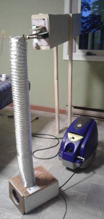 (28th) I decided to try it
out with my Michelin compressor (~800 W). I
set it to 48 PSI. I figured it wasn't really enough radiator pipe, but
in the previous test the pipe had mostly cooled in the first foot or so
if not the first 6 inches. The room started at 15.6° on the digital
thermometer, maybe 15.3 on the glass one. At the floor it was 14.3. In
about 10 minutes the warm air was 15.8 and slowly rising.
(28th) I decided to try it
out with my Michelin compressor (~800 W). I
set it to 48 PSI. I figured it wasn't really enough radiator pipe, but
in the previous test the pipe had mostly cooled in the first foot or so
if not the first 6 inches. The room started at 15.6° on the digital
thermometer, maybe 15.3 on the glass one. At the floor it was 14.3. In
about 10 minutes the warm air was 15.8 and slowly rising.
With this compressor running one could feel the air
blowing in from the outdoor heat exchanger instead of just wafting. And
it didn't feel cold. After an hour or so I checked it with a glass
thermometer, which said it was ~16° - approximately the room
temperature. And outdoors it was 5°, and there was wind, getting
stronger and blowing heat away. Apparently the heat exchanger actually
worked.
The output fitting of the compressor was hot to touch even
for a moment. The thin air hose I had used was the only one with two
"F" ends that would connect the compressor to the pipes. One could feel
the temperature drop along its 2 foot length. And I thought I could
hear a leak somewhere, but I couldn't pin down where. Apparently a lot
of pressure was being lost
because it was too thin and its resistance to air flow was too high -
and maybe there was a leak, too. And the whole kitchen soon stank with
the heat of the compressor. Hot oil maybe? Well, all in the cause!
(When I disassembled it the next day, this little tube had a lot of
water in it, indicating the loss of pressure within. It may have been
the water spitting around that I was hearing as being a "leak".)
I set the outside valve at the end of the piping to give
it 55 PSI, to have more pressure with less airflow. By 35 minutes the
thermometer on the counter hadn't moved, but the air at the floor
feeding the radiator was up to 15.0. Perhaps the warm air was filling
from the counter height down to the floor before more warmth would
appear higher up? Then (after an hour) I found I neglected to close the
far door and was heating almost twice as much space as I thought.
Ten minutes later the digital thermometer said the room
was 16.7°. That was ~1° rise.
Then I got the temperature probe clamped to the pipe
between where it came out of the house radiator and went into the
outdoor exchanger. The pipe was 19.5°. That explained why the
incoming air was right at room temperature: the outgoing radiator was
warmer than the room. It also said there wasn't enough house radiator
for the compressor. The closer to room temperature the warm air was,
the higher the COP could be.
After 1-1/2 hours the room was at 16.8°. It wasn't
warm, but discernibly warmer. Was it warmer - or the temperature
dropping less - than 800 watts of compressor motor by itself? By the 2
hour mark it seemed to have gone down, to 16.4° But the air
pressure had kept creeping up. I suspected higher pressure (over the
meter scale's 60 PSI max) was meaning less air flow. I went outside and
adjusted the valve to get 38 PSI. It sounded like way more air hissing
out. In 20 minutes the warm air (radiator) temperature hit its highest
yet, 18.1°, the air coming in through the outdoor heat exchanger
was at ~14°, and the room crept up to 16.6°.
In the last tests the 425 watt radiant heater had raised
the room only .2° in an hour. I decided to bring in another heater
that would make it 925 watts, and see what happened to the room
temperature in another hour. What a relief to turn that compressor off!
Somehow I looked after I turned them on and the room said 16.3°,
just a couple of minutes after it had said 16.6. ???
I thought the heat pumping hadn't been very effective and
that the temperature would start to rise with 900 watts of radiant
heat. It only went up .3° in an hour, back to 16.6. It seemed the
wind was making the
windward side of the house a lot harder to heat than the day before.
I turned the heat off for an hour (during which the power
quit - another tree across the power poles?) and the temperature
dropped to 15.3, a 1.3° drop. (Compare with pervious night:
-.9° and -.6° in two like tests.)
The Michelin
compressor
connected with a copper pipe from the tank's
drain spigot, with a gratuitous picture of the "LED indoor
garden":
Coffee, lettuce, spinach, scraggly cherry tomato, carrots, all on
rollers
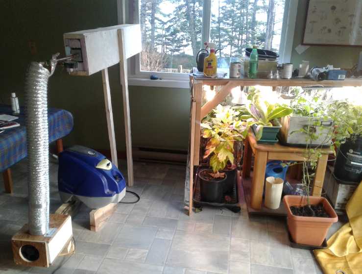 (29th) I tried out the
system again with not dissimilar
unsatisfactory
results. This time I replaced the thin hose with 1/2" copper pipe. It
came as straight out as possible: 1/4" to 3/8" adapter; 3/8" threaded
elbow; 3/8" to 1/2" copper pipe clamp fitting; 2 foot copper pipe to
fan box; copper elbow (soldered); "stegosaur" finned pipe going up;
elbow to pressure meter "T" and ouside heat exchanger. In spite of the
solid copper pipe attached to the compressor, The fittings on the
bottom of the compressor were burning hot, the 2 foot pipe cooled to
"just hot" going into the fan box, and the finned pipe at the box exit
was just warm.
(29th) I tried out the
system again with not dissimilar
unsatisfactory
results. This time I replaced the thin hose with 1/2" copper pipe. It
came as straight out as possible: 1/4" to 3/8" adapter; 3/8" threaded
elbow; 3/8" to 1/2" copper pipe clamp fitting; 2 foot copper pipe to
fan box; copper elbow (soldered); "stegosaur" finned pipe going up;
elbow to pressure meter "T" and ouside heat exchanger. In spite of the
solid copper pipe attached to the compressor, The fittings on the
bottom of the compressor were burning hot, the 2 foot pipe cooled to
"just hot" going into the fan box, and the finned pipe at the box exit
was just warm.
It would seem that most of the heat wasn't being
transferred from the compressor to the air, or from there through the
pipes. What seemed to be needed was to start the radiators right at the
compressor so that it didn't itself get hot. And not go through some
constricted 1/4 inch fitting - that was probably where the heat was
being lost! And not even have a pressure tank - that could be replaced
by all that radiator and heat exchanger piping.
It had worked best in the first test where the small
compressor was right inside the fan box. How could that be done with a
large compressor -- especially if the compressor was to be kept out of
the living space?
Later: I think the pressure inside the compressor cylinder was much
higher than what I was allowing in the pipe, and so there was far too
much flow and high pressure drop inside the compressor. I should have
run with much higher pressure to match the compressor, with less flow.
I limited it to 60 PSI simply because my pressure gauge only went that
high. Duh! How about a new gauge, then?
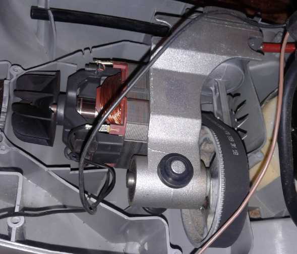
Inside the Michelin Compressor.
Typical cheap piston with no pin tilts back and
forth as it goes in and out of open bottom cylinder.
Compressor Noise
Solutions?
(27th) Here is what may be the most practical answer to the
compressor noise problem. It is similar to "conventional" heat pumps:
have the compressor outside the living space.
* Put the compressor outdoors in an insulated box. Unlike the
"conventional" system the box is insulated instead of ventilated, and
stays at indoor temperature.
* Two pressurized air pipes go through the wall from the box into the
space to be heated: supply to and return from the space heating
radiators/indoor heat exchangers.
* The indoor-outdoor heat exchanger now has its inner end in the box
instead of in the house. As the compressor moves the air, it is warmed
from outside to (almost) room temperature coming in this heat
exchanger, is compressed and thus heated by the compressor, flows
through and heats the house, returns at (just above) room temperature
to the box, is cooled (almost) to outdoor temperature by going out this
heat exchanger, then is further cooled (colder than outdoor
temperature) as it decompresses to the outdoors. Because the air is
returned from the house at room temperature, the incoming air is heated
to room temperature, and so the heat pump still draws (roughly) room
temperature air for the fantastic COPs that result from the small
"lift".
On behalf of the neighbors, the "sealed" box enclosure
with insulation will hopefully make it quieter than "conventional" heat
pump equipment where a big fan and the compressor are in the open air.
The most sound is likely to be compressor noise coming out the open end
of the indoor-outdoor heat exchanger. The nature of the insulation in
it could have a considerable effect, and a 180° bend or two might
also dampen sound.
The one negative to the arrangement is that if the
indoor-outdoor heat exchanger was in the house, it would supply fresh
air, at room temperature.
I suppose it would be possible to still do this if the
outer tube of the radiators went into the house from the box and ended
indoors, and then a return tube went through the wall back to the box.
But the ducts would transmit the compressor noise.
Custom Air Pumps?
(29th) With the tests of the large air compressor showing highly
unsatisfactory transfer of the heat from the compressor to the output,
and yet with the first little compressor located inside the fan box at
least showing that air heat pumping worked with a fair COP, it would
seem that a better configuration - probably including a better air
pump/compressor - was the key.
I had been contacted by one Peter of ReliableSteam.com .
Since that business used lots of pistons I asked for his thoughts on
how one might get a quiet compressor. He said the way to make them
quieter was with long cylinders and long piston stroke. That made sense
since probably much of the noise is the valves opening and closing at
the ends of the stroke. And slower strokes moving more air per stroke
would be quieter. Peter suggested a hydraulic cylinder with a piston.
At this point we're talking about making a custom air
pump. That would doubtless be far more ideal than a stock air
compressor... but how far do I want to get into this? OTOH, I have
spent a fortune on electric house heating over the years (mitigated by
a lot of firewood cutting, splitting, hauling and stacking), and so has
everyone else in cold climates. Having a way to do it cheap with very
low electricity use would be more than a little appealing - and
something to commercialize. Considering they would be relatively low
cost, not very hard to install, and far lower cost to run than anything
else, tens of millions of them would be bound to be made and installed!
Okay, how about this? A long cylinder with copper heatsink vanes on the
outside:
* Wide open air entry (with filter) at the input end
* a large one-way flap at the compress end
* The entire cylinder (or at least the compression end) and a large
copper output pipe has heatsink vanes
* a large one-way flap in the top of the piston
1. In the compression stroke, as soon as the pressure in the cylinder
is higher than that in the output piping (which replaces having a
pressure tank), the clyinder flap will open and for the rest of the
compression stroke, until the piston reaches the top, the air will
enter smoothly through the flap.
2. In the back stroke, the pressure in the piping pushes the output
flap closed. As soon as the pressure in the cylinder is less than the
outside air, the piston flap opens, allowing fresh air to enter for the
rest of the stroke until the cylinder is full when the piston is at
bottom. Then the next compression stroke starts.
The entire unit is enclosed by house heating duct (it's
"in the box") with air blowing past it as part of the radiator system.
The heatsink vanes around the cylinder and output pipe are the start of
the radiator system. The compressed air then feeds into the rest of the
finned piping and finally to the outdoor heat exchanger.
Now... how should we drive the piston? Typically one would
use a motor and have a crankshaft, giving a sinusoidal motion. But what
about simply using a solenoid? Instead of just having the piston just
switch on and off, a microcontroller could give it a soft start and end
both to optimize the effectiveness and to keep it quiet.
===
(30th) It occurred to me there was another option, by itself or in
conjunction with quieter compression: I could put a variable frequency
drive (VFD) on the compressor motor. If one cut the speed down (eg in
half, 30 Hz) not only would the compressor noise level drop but the
output air could be adjusted to match the piping and the heating load.
It seemed to me Jim Harrington had told me he gets VFDs for not so much
more than 100$. This seems like a simpler plan!
(Oh, wait... The motor in this compressor has brushes. I
may need a PWM control instead of VFD. I'll have to see what's in the
new compressor when it arrives. PS: Brushed motors with field coils
aren't the most efficient type of motors, either!)
At this point I decided I had done more than enough on
this project for January. But I took the air compressor apart and had a
look. The piston was driven by a toothed belt - good. But the air from
the cylinder went through a skinny little hose to the tank - probably
under 1/4" diameter inside. I had bypassed most of the other
restrictions in the last test by attaching to the tank's drain cock
hole instead going through the output regulator. But it seemed pretty
clear that the air was being forced through some narrow spaces inside
the compressor and probably most of the heat was being generated within
it instead of going to the piping - as evidenced by the high
temperatures at the compressor.
The next choice would have been to disconnect the tank
entirely and go straight from the cylinder to the piping. That probably
would have helped, but a bigger exit hole in the cylinder would have
been better. I decided to reassemble my compressor as I needed it for
typical compressor tasks, and await the larger one that I had ordered.
(It arrived February 2nd)
Refrigerator Air Pump
On February 1st I went to the refuse transfer station and
picked up a refrigerator type compressor from a discarded office water
cooler. I found it quickly pinned the needle on my 0 to 60 PSI pressure
gauge. But it pumped a low volume. By putting a balloon over the output
and measuring its size after 90 seconds (Volume = 1/6 pi D^3),
I
concluded
that
it
only
pumped
around 0.17 cubic feet per minute even
at low pressure. It also only drew only 80 watts of power. Perhaps I'll
try this one in place of my lab pump, at a fairly high pressure.
I complain about refrigerator compressor noise, but
they're much quieter than any other compressors. This one I could
actually tolerate to leave running if it was heating a room almost for
free. At least if I wasn't in the room much. Or how about in my travel
trailer? I could eliminate the continual 500 watt portable heater drain
and (hopefully) have it warmer in there with 80 watts, and I wouldn't
hear it at all from the house.
My
Solar
Power
System
Month of January Log of Solar
Power Generated [and grid power consumed]
(All
times are in PST: clock 48 minutes ahead of sun, not PDT which is an
hour and 48 minutes ahead. DC power output readings - mostly the
kitchen hot
water heater for some months, then just lights - are reset to zero
daily (for just lights, occasionally), while the others are
cumulative.)
Solar: House+DC, Trailer => total KWH [grid power meter
reading(s)@time] Sky conditions
Dec. 23rd 08.31.(.53), 926.71 = 0.42 [69987@17:00] dull.
(I was away Dec 24th until Jan 2nd)
Jan 02 08.31,(0), 926.71 = 0000 [70401@18:30] sleet, rain,
dull. OUCH! Over 41 KWH per day keeping the house at 12°c over the
holidays. That's a main reason I have a woodstove. I couldn't afford
the power bill to keep it at livable temperature full time
electrically. With everything so cold to start (and the woodstove being
no great performer), it took a good bundle of wood and 3 or 4 hours to
get the livingroom tolerably warm when I got home. The rest of the
house stayed pretty chilly.
3rd ?
04th --- [Car 72 Km, chj, 55 Km, chj; 70476@15:00] Cloudy 3rd &
4th. Snow on 4th early AM, then sleet, misty drizzle. Bit of sun. The
solar equipment is still shut off.
05th --- [70533@23:30] Snow. Clouds
I turned on the grid tie inverters on January 6th (@ 11 AM
PST - 2 hours before actual noon), but the solar panels were covered in
an inch of snow. I tried to sweep it off the two panels on the lawn,
but it had become crusty and hard, and wouldn't come off. Furthermore,
there were tree shadows on all the house panels. Only the trailer roof
ones were in full sunlight. So 3440 watts of panels were making only a
few watts.
At 12 "PM" (really AM - still almost an hour before noon)
I got the snow off one panel on the ground and it was making 200 watts.
A while later the snow had softened on the other and I swept it off. A
very light cloud I hadn't even noticed brought production down to 100
watts instead of up. But not so long after it was up to 300.
By noon those panels were in tree shade. The panels on the
roofs started melting from the top down, but the bottom lip of the
frames kept it from all sliding off, and panels are only as good as
their darkest cell, so there was still almost no production on the
first sunny day in January.
06th 00.66, - , 926.84 => 0.79 KWH [70563@18:30] Mostly Sunny
07th 01.57, - , 927.02 => 1.10 [55Km,car charging; 70600@
16:30] Sunny. 10 panels still have snow (@end of day)
08th 02.33, .11, 927.23 = 1.08 [70645@16:00] clouds AM sunny
later PM. 9 panels still have snow, only one completely cleared.
09th 02.53, .12, 927.24 = 0.34 [70687@17:30] Cloudy. +3°.
Egads, I'm not even driving anywhere, and the woodstove is on! That's
an awful lot of power for bedroom heat, even in the cold weather.
Besides the trailer (500W) do I have some heater on I'm unaware of? 9
panels still have some snow. A wind came up after dark and melted the
snow.
10th 02.99, - , 927.54 => 0.76 [70718@16:00; 95Km,chj] Clouds.
(But panels clear of snow)
11th 02.03, - , 927.56 => 0.06 [55Km,chj; 70780@17:30] snow.
dreary. dark. dim. dismal. Turned off 3 of 4 inverters at dusk. Snow
after dark covered the solar panels again.
12th 02.04, - , - => 0.01 [70804@23:00] Overcast. -7°. In early
PM I tried to sweep off the panels on the ground, but the snow was too
icy and crusted. (I did thin it.) There is of course no point comparing
4 snowed-over panels on one inverter with electricity consumed. Yes,
there are electric heaters I haven't been thinking of: In the garage
near the kitchen. At -7 outside, they are working hard to keep the
garage at +7°. The 240V/60A double breaker to the shop blew. I
reset it. It was okay. ??? (The open loop heat pump described in this
issue should use less electricity to heat the whole house nicely than I
am presently using for the bedroom at night and to keep that garage
from freezing!)
13th 03.40, - , - => 1.36 [60Km,chj; 70894@21:00] light snow, light
overcast. Low: -8.2° I went into town, and when I got back, I
noticed the snow had melted off the 2 panels on the lawn. Even more
surprising, they made over 1 KWH of electricity. (sun msut have come
out?) EGADS, WHAT could possibly have used 90 KWH of electricity in ONE
DAY?!? Double every other day?!? Hmm, I guess in this extreme cold,
some of the house baseboard heaters (set to 10°) are coming on at
night when the fire is low. OMG the next electric bill will be murder!
Must keep the stove going higher at night!
14th 03.62, - , - => 0.22 [70930@17:30] Mostly overcast (sun glowed
a bit a one point). Still just 2 panels clear of snow.
15th 03.73, - , - => 0.11 [70978@16:00] About same as yesterday,
periods of light snow, -6 to -9. Snow accumulated at the bottom of the
two solar panels that had been clear.
16th 03.86, - , - => 0.13 [71031@16:30; 45Km,chjng] slightly sunny
then overcast, then snow, then blizzard. -3°.
17th 00.01,~2,- => 2.01 [71078 (Est.)] More snow. Around 0°.
Wind. Power went out in evening before I took readings so everything is
an estimate. Windplant was very active. It charged the batteries and
then some, and I put on a 500 W heater directly on the rectifier
output, before the charge controller. All solar panels covered with
snow.
18th - solar production off - [71114@20:00] Windplant was overcharging
- the voltage even with the heater on was a little too high for the
charge controller (ie, above battery voltage -- it only boosts, not
reduces voltage. Heater: 40 V = 1/3 voltage, 1/3 current, so 500 W / 9
= 56 W. The heat was quite perceptible. I turned the kitchen hot water
heater on to provide more load. Then of course the wind dropped off,
and I turned it off again. Soon the wind died completely) AM Overcast,
+3° - the snow is getting wet, heavy and slushy. Evening (20:00),
+1°.
19th 00.25, - , 928.08 => 0.77 [71143@17:30] A bit of sun but
not much. (Lots of jet trails.) +4° in PM. The snow had melted off
the 4 trailer roof solar panels, and I swept it off the 2 on the lawn.
So I turned on their 2 inverters and 6 of 12 panels were working.
Whoopee, 3/4 KWH for the day!
20th 00.70,.35*,928.81 => 1.53 [71166@17:30; 55Km,charging] AM
SUNNY! +2°. Not for long - PM overcast. A lot but not all of it
looked like high altitude jet trails again, back and forth, back and
forth, almost from one end of the sky to the other. The snow slid to
the bottom then almost disappeared off the four top solar panels on the
house. The bottom two were still not wholly uncovered. I turned on the
other two grid ties. *From windplant
21st 01.69, - , 929.44 => 1.62 [71206@17:30;
55Km,charging] Overcast. (The snow musta come off the other panels.)
22nd 01.87, - , 929.56 => 0.34 [55Km,charging; 71241(?)@17:30] Heavy
overcast & rain. +5°. Snow is reduced to patches.
23rd 03.28, - , 930.52 => 2.97 [71473@17:00] Overcast AFAIK. I
don't get it.
24th 04.52, - , 931.32 => 2.04 [85Km,charged; 71313@20:00] AM
started sunny with normal tropospheric scattered clouds 7°, then it
got largely overcast.
25th 06.05, .3*,932.77 => 2.88 [55Km,charging; 71334@17:30] Sunny
AM, then jet trails, clouds - overcast.
26th 07.02, .1*,933.48 => 1.78 [71366@16:30] Uniform gray overcast.
27th 09.22, - , 934.96 => 3.68 [71396@17:00] Wow, a mostly
sunny day!
28th 09.90, - , 935.36 => 1.08 [55Km,charging; 71430@17:00]
Overcast again, 2 to 5°; Power fail at night.
29th 01.35, - , 936.14 => 2.13 [71459@21:30] Mainly Overcast.
5°,
30th 03.67, - , 937.24 => 2.42 [71483@17:00] AM overcast, PM
mostly sunny, 4-7° (morning was warmer).
31th 03.76, - , 937.32 => 0.17 [85Km,charging; 71512@17:00]
dull. dreary. dim. rain. 3°.
February 1th 04.02,-, 937.33=>0.27 [55Km,charging; 71555@17:00]
Mostly dull, snow 0°. Collectors covered with snow except the two
on the lawn, which are set at a steep angle.
Feb. 2th 05.06, - , 937.55 => 1.26 [71590@16:30] Sunny. 10 panels
still covered in snow. 1 was clear by late afternoon.
Feb. 3th 05.39, - , 937.78 => 0.56 [71620@17:00] overcast &
rain,
3°. Solar panels were clear of snow (at end of day).
Daily-
KWH- # of Days (January)
Made
0.xx - 17
1.xx - 7
2.xx - 6 (1 day it was from the *windplant) - otherwise all near
end of month.
3.xx - 1 (near end of month)
4.xx -
5.xx -
6.xx -
7.xx -
8.xx -
9.xx -
10.xx-
11.xx-
12.xx-
13.xx-
14.xx-
15.xx-
16.xx-
Monthly Tallies: Solar Generated KWH [Power used from grid KWH]
March 1-31: 116.19 + ------ + 105.93 = 222.12 KWH - solar [786 KWH -
used from
grid]
April - 1-30: 136.87 + ------ + 121.97 = 258.84 KWH [608 KWH]
May - 1-31: 156.23 + ------ + 147.47 = 303.70 KWH [543 KWH] (11th
solar panel connected on lawn on 26th)
June - 1-30: 146.63 + 15.65 + 115.26 = 277.54 KWH [374 KWH] (36V, 250W
Hot Water Heater installed on 7th)
July - 1-31: 134.06 + 19.06 + 120.86 = 273.98 KWH [342 KWH]
August 1-31:127.47 + 11.44+91.82+(8/10)*96.29 = 307.76 KWH [334 KWH]
(12th panel connected on lawn Aug. 1)
Sept.- 1-30: 110.72 + 15.30 + 84.91 = 210.93 KWH [408 KWH]
(solar includes 2/10 of 96.29)
Oct. - 1-31: 55.67 + 13.03 + 51.82 = 120.52 KWH, solar
[635 KWH - from grid]
Nov. - 1-30: 36.51 + 6.31 + 26.29 = 69.11
KWH, solar [653 KWH - from grid]
Dec. - 1-23**: 18.98 + .84 + 11.70 =
31.52
KWH, solar + wind [711 KWH + 414** = 1125 from grid]
Jan. - 2**-31: 17.52 + ----- + 10.61 = 28.13 KWH, solar+
wind [1111 KWH from grid]
11
month total March 1 to January 31: 2104.15 KWH made; [6964 KWH
consumed
from grid]
** On December 24th I went away for Christmas until January 2nd, and I
left the solar equipment turned off for safety. (And I kept it off
until
January 6th, there being power bumps and flickering lights.)
Things Noted
* Solar panels don't work covered in snow.
* December and January solar collection was only around 10% of that of
the spring and summer months. The days are short, the angle of the
solar panels is poor for the low winter sun and occasionally snow
covered the panels.
* Tons of grid power was used in heating, especially in December when I
was away, and in the very cold weather in January. Next winter (I hope)
we'll see what changes with free air heat pumping!
* If I get the open loop air heat pumping installed and working, if it
proves makable by an amateur such as myself and practical, winter
electricity consumption will drop dramatically and annual totals by
perhaps 25 to 35%. (It must be remembered that a significant portion of
the total consumption is for driving - recharging the car. The "ultra
efficient" EV if I ever get it going could drop that portion of the
usage by maybe 1/3 as well.)
Woodstove
Electrical
Generator
with
Closed
Cycle
Steam
Engine?
Pressure Release Cycle Valve?
(6th) I had the idea a couple of times that it would be nice to open a
valve to prevent pressure buildup while the piston was descending. But
how would it be activated? It almost seemed like it would need a second
rod to the flywheel, activated at at different angle than the piston -
a la the Stirling engine.
Now I came up with an at least somewhat easier plan:
* Have the valve on the underside of the chamber separator. Up is
closed, Down is open.
* Give it some weight so that if there's no pressure underneath it
falls down into the "open" position.
* Have the piston operate a lever so that just before the bottom of its
stroke it pushes the valve closed and holds it there until the piston
is moving up again.
* The pressure building up holds the valve closed as well as
pushing the piston back up.
* When the piston reaches the top of its stroke the pressure is
relieved and the valve falls open again.
* Again as the piston descends the valve is open.
I'm not saying I'm going to build this, and certainly not
for the first rendition. It would mean pressure is escaping while the
piston is going down. If the pressure is building with heat from the
stove while the piston is descending, it pushes against the descent.
(Note: the vacuum is also building in the top compartment as it cools.)
But that built up pressure is still there as the piston rises again,
helping to push it up just as much as it hindered the fall. So overall
it has no net effect. The pressure building as the piston is at the
bottom and on the way back up is what drives the engine either way.
The offset cycle with the piston descending rapidly and
rising slowly is surely the way to maximize use of the pressure
buildup, because then most of it assists the power stroke. The main
effect of the valve would probably be a potential to reduce noise, as
there will be less total pressure in the "pop" when the piston hits the
top of its stroke and the compartment pressures equalize.
BUT with the new house open loop heat pumping idea, I
decided
to put the generator on hold for now. One can only work on so many
things. (And I would have LOVED to have had some cheap heat this month!)
Woodstove
Electrical
Generator
with
Thermoelectric
Generators
(TEGs)
I used to think that a TEG
sitting on the woodstove would need overtemperature protection. Now
I've seen that with my present stove, the top never gets hot enough to
burn out TEG modules. That simplifies it immensely.
One other reason I have been reluctant to start an
otherwise simple project was that I would have to build a unit with
enough TEG modules to make say 14 volts in order to at least be able to
charge a 12 volt battery, and 3 times larger to charge the 36 volt
solar system. And there's an uncertainty factor of just how many TEG
units it would take to do either of those.
It also didn't seem it would make a lot of power. For 100
watts they might be worth it. For 20 to 50, not so much. So the
complications and uncertainties seemed like to much bother.
Another complication was that it seemed to me that for
best effect the heatsinks for the TEG cold sides should be over the
edge of the stove to catch cool air, rather than on top. But the TEG
powered air fan I already use could draw cool air across the top of the
stove and blow it across the heatsinks. That again simplifies it.
But I do have all the parts. They've sitting around for
quite a while now - most of them for some years.
It has occurred to me that I now have DC to DC up
converters. I can take even a very low voltage and convert it to a
regulated higher DC output voltage. That changes the picture. As long
as the TEG puts out enough voltage it can have any desired output
level, and there's a 36 volt plug near the woodstove, so the output can
easily be used to charge the solar power system batteries - by feeding
into the plug instead of drawing out from it, like the Chinese grid tie
inverters. That makes it simpler; more
practical.
I decided to make separate sets of four modules, each set
using one heatsink and aluminum stovetop plate. The plates would be
larger to gather heat from the surrounding area, not just the stovetop
right under the heatsink. These units would be wired in series, 2 or 3
or 4 of them perhaps. First one for a test, then two, then more if it
seemed worthwhile. (5 would be about all that would fit. I have 3 good
heatsinks and 2 acceptable.) Since the stove top isn't really flat,
multiple smaller plates will sit closer to the surface with 3 contact
points each instead of 3 total. and allow buildup in small modular
sections.
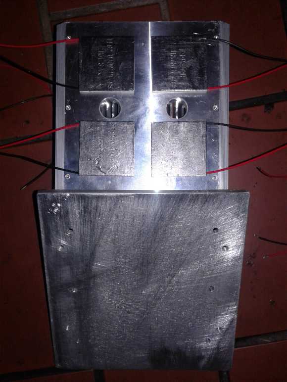 Module 1: Aluminum plate, aluminum
finned heatsink and four TEG modules
(15th) I drilled out bolt holes in a 6"
x 7" x 1/4" thick aluminum
plate I had on hand and put one unit together. I put it on the stove
and soon got 3.6 volts. I shorted the leeds and got 1.5 amps. Without
measuring an actual proper load, one might perhaps get 3 volts at 1
amp: 3 watts or so. Two units would then be a whopping 6 watts. If I
recall correctly the DC to DC boost converters need at least 4 volts
input. Well, I had figured it'd take at least two (8 TEGs) to do
anything useful.
Testing on the woodstove
But to my surprise the TEG powered woodstove fan proved
wholly inadequate to cool the heatsink. The voltage started dropping as
the TEG top sides and heatsink warmed up. I set it down on the hearth
before it got too
hot to pick up. I hadn't counted on the high conduction of heat across
the TEGs. Some better system of cooling the tops would be required.
That took me back to a previous design idea: one with circulating water
for cooling.
That sounded a lot more complicated. For how many watts,
again? Under 20? I decided I had better things to do.
Electricity Storage (Batteries)
Turquoise
Battery
Project:
Long
lasting,
low
cost,
high
energy
batteries
Current Collectors: Sheet Metal or
Thinner Metal Foil?
The copper sheet I bought was called "copper foil" (~.10
mm thick), but it's a lot thicker than typical aluminum foil (~.02 mm).
It occurs to me it doesn't really need to be. Gold plating may be
costly, but copper itself isn't cheap either. And having anything any
thicker
than it needs to be is just extra weight per unit of energy storage.
It's no problem sticking with .1 mm for test cells, but I should
probably look for .05 mm or less for production.
And maybe the zinc doesn't need to be more than
electroplated foil either. After all, most of the surface area and
hence available reaction energy must be in the fluffy zinc
electroplating, not the sheet. But since the surface of the zinc sheet
does take part in the reactions, there is probably a minimum
thickness for it to maintain cohesiveness. Well, to be determined
in testing I suppose!
With foil, thin, flat "sheet of paper" size batteries may
be the most practical form. (Think "sheet of corrugated cardboard"
maybe, for an actual size and thickness?)
Next Zinc Electrode: Pure Zinc
(12th) Having obtained some supposedly pure zinc on AliExpress, I cut a
piece for the
electrode for the flat cell. I dipped it hydrochloric acid to etch it,
and was amazed: It didn't turn black like the roof moss killer zinc! It
kept its zinc color except for looking duller. It was like a different
metal! I should have tried this much earlier, but I didn't know where
to order any from. Perhaps my main problem
with the other zinc was impurities?
I put it in the electroplating tank at 400 mA for an hour.
Presumably that would give it almost 400 mA-H of capacity in the
plating, plus whatever little the surface of the sheet zinc itself had.
It didn't plate very evenly. But the back was the worst, so I decided
to use it even if it had less than 400 mA-H.
As usual I forgot to weigh the zinc before I plated it, so
we must rely on a left over piece of the same sheet and some
mathematical contortions:
Leftover piece: 99x33mm, 4.75g = .00145 g/sq.mm
Measured/calculated area of actual piece: 64x31+34x9mm = 2290 sq.mm
Weight of actual piece before plating: .00145 * 2290 = 3.3g
3.70g(plated) - 3.3g(unplated) = .4 g of plating
.4 g * 820 mAH/g = 328 mAH (Pfew!)
Cell Cover
Along with
making the zinc electrode I cut two pieces for
the removable cover over the cell. I got them to fit pretty tightly (to
minimize air leakage) and I was afraid the small piece might be hard to
pull off, so I put a nylon pan head bolt into it for a handle.
On doing this I realized that if I simply put the water
reservoir at the other end it could just have one longer cover over
everything. Putting it at that end was just a hangover from cells that
stood on end, when that was the top. Oh well - for the next one.
Nickel Trode
(13th) I painted a little calcium hydroxide onto the gold plated copper
current collector sheet. But the immediate goal was to see how well the
pure zinc worked in the negative side.
I took a second NiMH D cell out of its can some time back.
Seeing my last NiOOH electrode hadn't worked well, I decided for the
moment to just use pieces from the commercial one. That I can easily
reopen the cell and swap out electrodes has its advantages. I cut
pieces and as it was so thin (.7mm) I put in 3 layers. No doubt with
the salt electrolytes and under pH 14 the nickel mesh will oxidize.
Let's see how well it works after that. (And let's hope I haven't
scratched the gold plating on the copper! I'm really not fussy about
trusting a plating. Oh well.)
I also painted a little samarium oxide onto the pieces,
hoping it will soak in and raise the oxygen overvoltage of the whole
electrode, with the (sulfonates) Sunlight dishsoap to make it a gel.
Zinc - Again
(14th) I opened the fridge and took out my agar gel with zircon
additive. The cover had shifted and it was completely dried out. From
now on I'll make a new tiny batch for each new electrode and not try to
save any. It would have to be painted onto the electrode instead of
just dipping the whole electrode into the "vat". At least I had the lab
heater now instead of just the microwave or a stove burner.
But I started having second thoughts about the
electroplating. The new zinc was pure, but the electroplating solution
had been made from the old zinc. A layer of black crud had to be fished
out of the bottom after making it. What impurities might be lurking
still in the solution and making the zinc plating impure, perhaps in
some deleterious way?
I had the powdered zinc electrodes from disassembled
alkaline cells. I decided to make a whole new batch of zinc chloride
from some of those, and redo the solution and the whole electrode. I
put some of them in a beaker of distilled water to dissolve out at
least most of the potassium hydroxide. Then I put them in the same jar
(cleaned) and added distilled water, then hydrochloric acid. There
wasn't a lot of reaction compared to the previous time. A lot of the
zinc stayed on the bottom and the acidity stayed at pH 1. Probably much
of the zinc was zinc oxide.
I filled the jar with more water and put in the new
electrode and a piece of the new zinc for an anode. I plated 1/2 an
amp-hour or so. The coating in the acidic solution was very different
than in the neutral pH zinc chloride, not 'fluffy' but solid "mountain
ranges" on a seemingly almost unplated background instead of "towering
trees
with many branches". I can't think but that these must have far less
surface area - but they also don't crumble off. Perhaps I can find a pH
that will give some "optimal" result, a more solid yet still somewhat
fluffy coating, perhaps at pH 3 or 4. Or perhaps a higher or lower
current would give a more uniform as well as more desirable result.
That last would be easy. I decided to try it: instead of
400 mA I would try 800 and then 200 and see what happened. Next time!
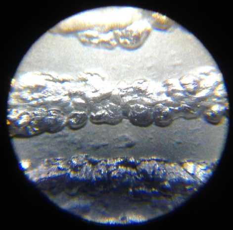
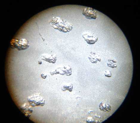 The odd patterns of plating
attained with
the acidic plating solution
The odd patterns of plating
attained with
the acidic plating solution
And how much plating was there actually? As usual I forgot
to weigh the plate between etching it and plating it. Well, it would
have been about the same as the last one. Hmm... a bit shorter; perhaps
a bit less. Plated it weighed 3.75g.
3.75 - 3.2 = .55g
.55g * 820 mAH/g = 451 mAH. In theory. Depending on how much surface
area of the rather solid looking plating is actually in contact with
the electrolyte.
I got out the osmium doped acetal ester and painted the
surface. Later I did the agar with zircon, just a thin mix.
Testing
I filled the cell with nothing but potassium chloride
solution, full 35g/100cc strength, about 3:30 PM. On charge at 1.9
volts it drew 60-70mA, which dropped to 20 over an hour or more. A
little gold-orange color appeared in the electrolyte in the reservoir
area. I don't much like that!
After a while I checked the pH: 6-7. I had expected it to
be more alkaline. That's almost metal dissolving territory. I guess I
rinsed the KOH out of the NiMH electrode pretty well. I added a few
flakes of KOH and it rose to around 11-12.
As the day went on the cell held higher voltages longer
until by night it stayed up over 1.8 volts for half a minute. )Later
for many minutes.) The nickel side obviously wasn't anything like fully
charged yet. Overnight it dropped to just over 1.3 volts. Instantaneous
short circuit current went up from 1/2 an amp to 3/4, but it still
dropped to 1/4 amp after 10 seconds.
(16th) In running a few cycle tests, it appeared that the voltage
descended to around 1.5 volts in just a few minutes, then very rapidly
dropped down below 1.2. But after that it would run for quite a while
under 1.2 volts.
The zinc was either around -1 to -1.2 volts or it wasn't.
I came to the tentative conclusion that the nickel was only holding its
+.5 to +.6 volt charge where it was in the best contact with the trace
of samarium oxide oxygen overvoltage raising substance, and so when I
tried to discharge the cell, that rapidly dropped off... to something
else. (Or the gold could have been oxidizing at the higher voltage
level.) Was there a NiOH level not mentioned in the literature? Was it
dropping to Ni(0) metallic? But that should have been an even lower
voltage.
What I really wanted was the lower manganese dioxide
voltage which was easy to keep charged. But manganese didn't recharge
properly. That led back to the nickel manganese oxides, AKA nickel
manganates, as being a form of manganese that probably would recharge.
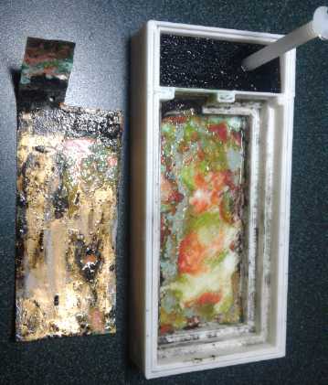 I took the
cell apart. The zinc looked okay. so far. The
copper tab had almost ozidized off right where the gold plating ended.
That was still being wetted with electrolyte that frothed up and left
slat crystals on the surfaces. The gold plating had also come off and
left exposed copper in three patches on the front and seemingly more on
the bottom. I knew I didn't like depending on a plating to protect a
metal! And the plastic bottom of the cell was very colorful with
various oxides - nickel, copper... and ???
I took the
cell apart. The zinc looked okay. so far. The
copper tab had almost ozidized off right where the gold plating ended.
That was still being wetted with electrolyte that frothed up and left
slat crystals on the surfaces. The gold plating had also come off and
left exposed copper in three patches on the front and seemingly more on
the bottom. I knew I didn't like depending on a plating to protect a
metal! And the plastic bottom of the cell was very colorful with
various oxides - nickel, copper... and ???
I suppose the other option is to go back to graphite
current collectors.
But the exposed copper could well explain the discharge voltages. It
was around the voltage of a copper-zinc cell. (Maybe that's what I
should make! At least it should work well, even if it's a little under
a volt.)
Copper Oxides Electrode
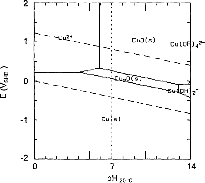 Hmm...
Maybe
not
a
joke.
After all, what I was doing wasn't working
well. And copper-zinc was used in some early batteries. Where was that
copper Pourbaix diagram?
Hmm...
Maybe
not
a
joke.
After all, what I was doing wasn't working
well. And copper-zinc was used in some early batteries. Where was that
copper Pourbaix diagram?
Let's see... at pH 7 to 12 it oxidized to Cu2O - a solid,
around 0 volts. At another +.15 volts, it further oxidized to CuO -
still solid... Or was it to Cu(OH)4-- ? What was that printed, off to
the right, for? That seeming a little ambiguous, I looked up some more
Pourbaix diagrams of copper. They conflicted with each other. One of
them called the products of interest "cuprite" and "tenerite", the
mineral names, and I had ot look them up to make sure they were Cu2O
and CuO. One said "insoluble in water" the other said "soluble in
ammonium chloride" but mentioned no other chlorides. Ammonium chloride
is slightly acidic and it probably depended on the acidity. This was to
be a "mildly alkaline" battery all along.
I decided to assume the products would be insoluble
around pH 12 unless trying it showed otherwise.
I checked on line for the resistance. No point looking at
it if it was an insulator... but then it had been used for batteries
before, so it couldn't be. One reference said it was, but others gave
"electron-volt bandgap" figures and wildly varying resistivity figures.
I stuck ohmmeter probes into the bag and got no reading, but some black
oxide stuck to them and if I pressed them together I got readings,
depending how hard I pressed, of megohms down to ten of kilohms. Good
enough, if mixed with conductive graphite.
Now... was it in the pottery supply catalog?
"Red copper oxide (cuprous)" and
"Black iron oxide (cupric)".
I thought copper compounds were green? Copper sulfate is
quite blue, copper II carbonate-hydroxide is cyan, and copper chloride
is cyan-green (IIRC). My gold plated copper current collector had
developed some green and some black - but some red underneath on the
case.
My copper sheet was disintegrating at the tab where the
gold plating ended - the tab was almost ready to fall off. I would
assume the green and black were the oxidized copper.
Next, how to get some. Of course I had lots of sheet
copper. Metallic copper was the discharged state. And I had a piece of
copper sulfate. Anything else? I went down to my storage and looked in
the box. Sure enough! A small paper bag, "1/2 lb BLACK COPPER OXIDE"
from the pottery supply. I don't remember buying it or why.
"Black oxide" would be the fully charged state, valence
+2, -- assuming it would charge electrically from cuprous to cupric
(unlike Mn2O3 refusing to charge to MnO2). And if it did, the charge
and discharge reactions would move two electrons instead of one, which
would be a big advantage in amp-hours per kilogram in spite of the
lower cell voltage. And there was some black on the back of the current
collector (as well as on the front) - promising! I was assuming that
both these oxides were at least somewhat conductive and not insulators
that would passivate the electrode.
So there were a few "ifs", and I've had my problems with
impure materials, but I thought this was worth a try. Here was the plan:
* Use a graphite foil sheet for the current collector.
* Mix the CuO with some graphite powder - just like with MnO2.
* Add some gell and compact it into a briquette.
* Try it out.
If it worked but had too low current capacity I could try
some of the fancier things like graphite fibers and gold plated current
collectors. The voltage is so low it shouldn't need any oxygen
overvoltage raising additive.
If it worked and barring more of the unforeseen problems
that seem to plague all my battery designs and plans, I could
apparently (and at last) make working batteries. I could experiment
with nickel manganates later as a higher voltage alternative.
How much? If again I wanted 1/2 an amp-hour in the test cell, and if it
moved 2 electrons in charge and discharge:
820 AH/Kg (Zn) * 65.4 / 63.55 = 843.74 (Cu)
But accounting for the oxygen: 63.55 / (63.55 + 16*2) = 665 AH/KG
The voltage may be low, but actually the amp-hours per
kilogram capacity makes nickel hydroxide (at 289 WH/Kg, IIRC) look
pretty feeble.
So for 1/2 amp-hour, a little under a gram: .5 AH / .665 mAH/g =
.75 g
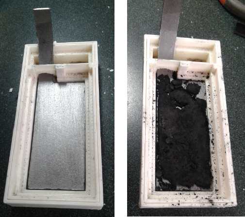 I had a feeling this was
going to make a very thin electrode! To hedge
my bets I decided to use 1.5 g. To this I added .3 g of fluffy
conductive carbon black (or acetylene black, or "incredibly fine
graphite" or whatever it's really called). Then I decided to double
that and added another similar spoonful, so around .6 g, and a little
of the sufonates soap for liquid. I pressed this to 5 tons. It made a
very thin electrode, which crumbled.
I had a feeling this was
going to make a very thin electrode! To hedge
my bets I decided to use 1.5 g. To this I added .3 g of fluffy
conductive carbon black (or acetylene black, or "incredibly fine
graphite" or whatever it's really called). Then I decided to double
that and added another similar spoonful, so around .6 g, and a little
of the sufonates soap for liquid. I pressed this to 5 tons. It made a
very thin electrode, which crumbled.
Test
It started out with 1.002 volts. Being that it should be
'fully charged' to start, and not seeing that there should be any
impediments, I expected that in spite of the low voltage it would give
solid performance. In fact, with a 56 ohm load, the voltage dropped
rapidly, each minute 25 mV lower than the minute before. In 10 minutes
it was hardly above half a volt. Most disappointing!
Thus, still the only cell I can claim worked really well
was the well known nickel oxides + zinc in potassium hydroxide. (And
yet we know from 'standard' dry cells that salt electrolytes do
work!) At least by gelling them they should last and last. Have I
accomplished nothing more interesting in all this time?
I went over TE News 135 where I had last tried hopefully
forming nickel manganates. It seemed to have worked, albeit again with
low current drive. What if I tried again with the new layout and ABS
plastic that wouldn't disintegrate, maybe with more KOH or even wholly
KOH solution?
Back to Nickel Manganates
Aside from disintegrating PLA plastic, the chief complaint
from the TE News #135 manganates was that it wasn't conductive enough.
I got out the jar containing the rest of it and added 5 more grams of
conductive carbon black to the remainder of the 5 original grams.
...Then I read further down in #135 and found I had already added 10
after that test back
back then. Now it should be up to 20. Any lack of performance now could
hardly be attributable to any shortage of conductive powder!
The flat cell seemed to be leaking. It had a pool of
liquid around it and kept needing a refill. I am getting SO tired of
leaking cells! Next thing to try would be a similar cell made with the
Cura slicer and finer printing instead of the old coarse Skeinforge
intended for the old RepRap printer.
Then I got into trying out the heat pumping idea
(somewhere above) and left project this for some days.
(29th) The internet was down - to the whole island (Still down Feb.
2nd!) - and in the evening
when I'm usually doing e-mails and web research, in OpenSCad I designed
my 100x100mm flat case to fit the zinc sheets of that size. But I
didn't 3D print it.
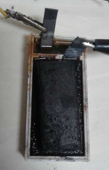 (30th) Having fixed the
leaking, and having been contacted about
potential collaboration in battery making, I thought it would be good
to confirm, if possible, that this was good electrode material. I mixed
10 grams of the "extra graphited" powder with 1.6 grams of
dishsoap/sulfonates gel. I put some in the compactor die and pressed it
to 6 tons. It weighed 5.3 grams and still looked a bit dry, in fact
spotty with some parts looking drier than others. I put it on top of
the graphite current collector in the bottom of the cell. I re-agared
the zinc 'trode, which had become dried out. I filled the cell with
about 7 cc of 20% KOH + 20% KCl.
(30th) Having fixed the
leaking, and having been contacted about
potential collaboration in battery making, I thought it would be good
to confirm, if possible, that this was good electrode material. I mixed
10 grams of the "extra graphited" powder with 1.6 grams of
dishsoap/sulfonates gel. I put some in the compactor die and pressed it
to 6 tons. It weighed 5.3 grams and still looked a bit dry, in fact
spotty with some parts looking drier than others. I put it on top of
the graphite current collector in the bottom of the cell. I re-agared
the zinc 'trode, which had become dried out. I filled the cell with
about 7 cc of 20% KOH + 20% KCl.
When I filled the cell, it was a minute or two before I
got a meter on it. I found it slowly rising at 1.45 volts. Just before
it looked like it would hit 1.5, instead it suddenly (a few seconds)
climbed to
1.68, and then inched its way up (minutes) to 1.705. Hopefully the
potassium permanganate and the nickel hydroxide were reacting together
to make nickel manganates.
I really have no certain idea of what voltage to expect.
Nickel oxyhydroxide voltage? Manganese dioxide? Something else?
A brief short circuit gave 450 mA, after which the voltage
quickly (seconds) returned to 1.69 more gradually to 1.701. Considering
it was a graphite current collector and that there had been no
charging, that seemed promising.
pH was about 13. The electrolyte turned transparent green
- no doubt nickel chloride. or maybe nickel sulfate with sulfate from
the gel? (Later: Wait, isn't potassium manganate green too? No internet
to look it up.) Maybe not enough gel, or the gel needed more time to
'set'? I
decided to let it rest for a while.
In an hour the voltage dropped to 1.691. Too bad the other
piece of lid didn't fit to keep air out. I tried another short short
circuit and got just 320mA, after which the voltage rose quickly back
to 1.67, and then crept up to 1.691 again. I had a weight on the main
cover. I removed it to no apparent effect, but when I put it back on
zillions of little bubbles frothed up where the terminals poked out.
Since it hadn't been charging, I assume those were oxygen coming off
the permanganate as it reacted. I also surmise the bubbles (under the
zinc) made for less electrolyte contact and hence the lower current.
In the evening, without
charging, I ran a load test with
60 ohms. This started at 1.678 volts but within one minute it was down
to 1.2 volts. It ran for 11 minutes before the voltage dropped under
0.9 . After a 1/2 hour recovery to 1.645 volts, still without
recharging, I ran it again and was surprised to get similar voltages
for 8 minutes. Then a third time... and a fourth time... each for
another 7 minutes. It was all just 10 milliamp-hours of current, but it
ran. But how many times could it be done, and why didn't it just run
much longer, once? A brief short circuit now gave about 250mA. The
electrolyte was now a very dark green.
Just because I was tired of doing it, I put it on charge.
With almost 1.9 volts in, it was soon taking only 8mA - half of what it
had been discharging at. I left it on a few hours, then off and in the
morning it was around 1.44 V.
(31st) Thinking back afew years that the nickel-manganate/manganese
cells had charged up to 2.6 or 2.7 volts, and that Zn was only supposed
to be about .3 volts less negative than Mn, I wondered why I shouldn't
be charging to higher voltage (Somehow 2.7 volts seems absurdly high
now, but it drove a load at 2.3 or 2.4 volts!) I turned up the power
supply to 2.5 volts. When I took off the charge, it quickly dropped
back to about 1.9 volts - the voltage of nickel-zinc - and from there
its fall slowed. But surely I needed to charge at a higher voltage than
1.8 or 1.9 for it to stay at 1.8. I set it to 2.3 volts and left it a
while. It still drew only 10mA. But the voltages started rising.
Low Currents - Back to Graphite Felt?
It seemed to me absurdly low currents might be the biggest
problem. Looking back at some TE News issues in #67 to #73, it seemed I
was getting far higher currents then than most tests recently from
similar electrode compositions in fairly similar electrolytes. What was
different? I was using not only graphite powder, but an electrode with
the active powder filling a piece of graphite felt and then the works
compressed into a brick. Apparently that gave much higher conductivity
than just powder, and higher than with the bits of graphite fiber mixed
into the electrode. Why does simple graphite powder work so well for
MnO2 in dry cells? Well, it would seem the thing to do is to go back to
what was working well in 2013.
As I recall, I put pieces of the the felt in with the
powder and shook the container. That wouldn't have done the best job.
What it really needs tho is a vibrator system: put the felt in the
bottom of a box (wall to wall foam), put powder on top, and vibrate it.
The powder should fall through into the spaces in the felt. And maybe a
square something over the top to add just a bit of weight (don't
compress the foam!) to push the maximum amount of powder in.
What did I have that vibrated? The air compressor was
pretty bad, but I didn't want to take it apart again and the outer
plastic case was quite damped. Some power tool? Too bad I don't have an
orbital sander!
I cludjed together a graphite felt electrode with some of
the same powder mix as the last one. I tried a similar discharge test,
but found a poor connection to the plus side. Probably it was because
the the current collector, which I had had to bend up for connections,
was slightly folded. It was by reconnecting below that fold that I got
good contact. This one ran for 28 minutes before it was down below 1.0
volts. BUT, did the last one, even with all that graphite powder,
perform poorly because its internal conductivity was poor, or because
of the same bad connection? Was the graphite felt superfluous?
I seem to have the most frustrating of problems with salt
electrolyte, throwing everything off. No wonder everyone has so far
gone for pH 14 alkaline where nickel metal doesn't oxidize, avoiding
the need for graphite current collectors.
Chemistry Seems Fine But Mushy Electrodes Don't Conduct Well
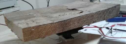 I did some
charging and then hooked up the 60 ohm load.
Voltage started dropping as usual. I put another spacer under the lid
so pressing down on it pushed the electrodes together, and pressed
down. Voltage came up substantially. So I added more weights. I think
it came up by over 100 mV. Then on top of this assemblage I leaned,
adding something like 50 pounds. It came up another 125 mV and was
dropping much more slowly. Practically a whole 1/4 of a volt more! (I
wondered how far I could go before powder oozed through the separator
grille and shorted the cell. Somehow it didn't happen.)
I did some
charging and then hooked up the 60 ohm load.
Voltage started dropping as usual. I put another spacer under the lid
so pressing down on it pushed the electrodes together, and pressed
down. Voltage came up substantially. So I added more weights. I think
it came up by over 100 mV. Then on top of this assemblage I leaned,
adding something like 50 pounds. It came up another 125 mV and was
dropping much more slowly. Practically a whole 1/4 of a volt more! (I
wondered how far I could go before powder oozed through the separator
grille and shorted the cell. Somehow it didn't happen.)
I ran another discharge test. The more weight I put on, up
to maybe 70 or 80 pounds, the higher the discharge voltage. The test
ran for 25 minutes, ending at 1.125 volts where it would have dropped
below .9 volts in half that time with no pressure. (I could have run it
much longer - an hour?) Then I hooked up the charge (2.2 volts) and
likewise found I could increase the charge current from 70mA to 90mA (a
~30% gain) by leaning on it.
On the morning of February 1st I tried another 60 ohm load
test, this time pressing heavily on the top the whole time. Results
were far better. In the previous tests, it was 1.112 volts after 5
minutes. In this one it never went below 1.3 .
There was the problem with all my plus electrodes, of any
chemistry, right in front of me. It was that the powders weren't being
held compacted. They absorbed water and expanded, losing conductivity.
I seem to keep learning this lesson over and over. What was needed was
either pressure in the cell holding it together (probably what makes
regular dry cells work) or else some construction of electrode that
would hold together by itself including when immersed in liquid (as
with lead-acid batteries). Chemically the electrodes were probably
fine. Mechanically they needed.... something. I'm sure still better -
much better - results than from just putting my weight on a mushy
electrode are possible.
That was what was appealing about the electrode shells
type of construction. Drying and very briefly torching them seemed to
help make them more internally solid too. In going over the old
newsletters it seemed I was getting better results in 2013-2014,
probably from that, so I'll try it again.
http://www.TurquoiseEnergy.com
Haida Gwaii, BC Canada