Turquoise Energy News #141
covering
February 2020 (Posted March 7th 2020)
Lawnhill BC Canada - by Craig Carmichael
www.TurquoiseEnergy.com
= www.ElectricCaik.com
= www.ElectricHubcap.com
Month
In
"Brief"
(Project Summaries etc.)
- Carrying Heat Uphill: A way to look at heat pumping - Open Loop
Air Heat Pumping Experiments - Another Higher COP Device -
Nickel-manganate/Zinc Battery
Developments - High Efficiency Titanium Dioxide Solar Cells and
"Pebble" Surface Cover Glass - NiMH D Cell Refill
In
Passing
(Miscellaneous topics, editorial comments & opinionated rants)
- Permian Period Amphibian Evolution (continued) -
Small Thots - ESD
- Detailed
Project Reports
-
Electric
Transport - Electric Hubcap Motor Systems (No Reports)
Other "Green"
Electric Equipment Projects
* End of the Solar Hot Water Tank (the mineral rich water stank) - Hot
Water Tank Protective Anodes
* Very High COP Open Loop Air Heat Pumping - With Water Cooler
Pump
- Means for Improvement? - New Heating Unit - Compressors Today Are Not
Made For Air Heat Pumping (& compressor design ideas) - Value of
the outdoor heat exchanger - Install & test of that - A Better Way
to join PVC Pipes to Copper Pipes (no pipe fittings) - The
Grand Potential - Additional Heat Pumping/Air Compressing Info Gleaned
From Web
Electricity Generation
* My Solar Power System: - Monthly
Solar Production log et cetera - Notes. - Analysis of a Whole
Year's Figures
Electricity Storage
* Turquoise Battery Project
(NiMnOx-Zn in Mixed Alkaline Salt electrolyte)
- Powder Electrodes Conductivity - Solid Porous Electrode
Briquettes; Plaster - Some theory/ideas - 50x50mm Electrode Compactor -
tests - Cylindrical Cells? - Okay, How About Flat With "Rebars"? -
Cupro-Nickel Current Collector
February is a short month,
but somehow this is anything but a short newsletter, and it has taken
me some time to complete it.
This month I continued
experimenting with the open loop air heat pumping (hoping to save
myself electricity and money and have a warmer kitchen as well as it
seeming to be an exciting and highly
valuable project anyway).
And I did some more work here and there on the new
chemie batteries. They're getting close! (...How many times have I
thought
that and had to stop and try a new tack?)
 Aside from that I did just a couple of little things
- some paint and plastic battery holders - for the ground effect
vehicle model. Its two powerful ducted fan motors need about 2750 grams
of lithium batteries to get full power, almost doubling the entire
weight of the model.
Aside from that I did just a couple of little things
- some paint and plastic battery holders - for the ground effect
vehicle model. Its two powerful ducted fan motors need about 2750 grams
of lithium batteries to get full power, almost doubling the entire
weight of the model.
There was no pipe into which two rows of the lithium cells
fit, or even one row fit nicely. I used pieces of the '1.25 inch
sprinkler system' PVC pipes, slit
them open and then shaped them by softening them in the oven.
And of course I did a little garden
raking/weeding/cultivating to prep the soil for spring. The 2019 crop
failures were staggering all over the world, shipping is way down, and
a few shortages have been reported in the USA with some large groceries
starting to limit the amounts of some items like flour, sugar and rice,
albeit to "5 bags" - more than most of us would buy anyway... so far.
"Ice Age Farmer" on youtube said hardly anyone he talked to was taking
the coronavirus threat seriously, so if just 3% of the population
trying to stock up was causing shortages, imagine what will be left
when everyone starts trying. So I want to grow more. At least I get
good potatoes and most of my fresh vegetables. Maybe it's time to build
that chicken enclosure?

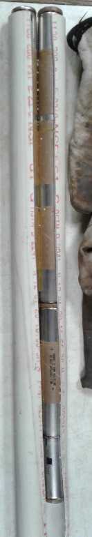
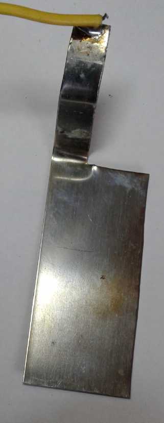
 The Fake and the Real
McCoy:
The Fake and the Real
McCoy:
The four prong implement on the right/top has been
my favorite gardening implement since I bought
it around 1980. I even put a new handle on it
when the old one rotted off. It's a rake, hoe and
cultivator, and one can pick up weeds with it,
shake off the dirt, and dump them in a bucket.
There's less bending
down, and when there is, it's a
loose weed, not a tug and break the root off.
The tines have never bent or broken. Maybe
a good tool to wield on a CNC gardening machine?
The imposter on the left/bottom is less useful, so
it just sits in the garage and its original handle
is still pristine.
Daylight started returning over the month and the solar
panels came at least somewhat back to life as the monthly tallies show.
But tops was under 6 KWH per day. March 6th and 7th made a dramatic
rise to
about 9 KWH - it was at last sunny (except for a couple of small - ugh
- snow flurries), and although it's still quite cold, the sun is
getting higher and the days are lengthening.
The end of February marks a year of logging solar PV
collection daily performance, and I made some notes on the annual
figures obtained. Overall the sun made 22% of my power, but it was 35%
in the seven best months. As expected the winter months were very low
collection, with high electricity use for heating. Even with the
woodstove doing most of it, 500 watts of heat in the trailer to keep it
from going mouldy added a big chunk to the total, as did bedroom heat
at night. And the electric car added some to the bill in all months.
Carrying Heat Uphill: A way to look at heat pumping?
Here's a visualization if we need to take some of the
seeming
magic out of the workings of a "conventional" refrigerant based heat
pump: There's a hill. It's not as high (as warm) as the occupants want
it. Instead of getting new dirt from elsewhere to make the hill taller,
they shovel dirt from the bottom of the hill and bring it to the top.
The work done by a heat pump may be seen as similar to the work being
done to bring the dirt up the hill. There's dirt (thermal energy)
everywhere, but
to make the top of the hill comfortably tall (warm), work must be done.
But it's less work and expense to "concentrate" existing, nearby dirt
into a hill than to get
all-new dirt delivered direct from the distant quarry (power company)
to make a hill.
Now, obviously the higher the ground is around the hill
(the less cold it is outside), the less work it is to bring up the
additional dirt, and higher COP ('coefficient of performance') is
obtained, and vise-versa: if the
hill towers above the frozen countryside, much more work has to be done
to carry it up and the equipment has more trouble doing it, too. The
work increases, but the COP gets lower.
The analogy is incomplete without noting that the sides of
the hill are continuously slumping off into the surroundings - the heat
gradually leaks out of the building, so more and more dirt has to be
brought up to keep the hill from shrinking until it's level with the
surroundings.
The analogy rather breaks down with the open loop air heat
pump. Here the compressor brings dirt from near the top of the hill and
piles it up a little taller in one spot. From there it spreads around
pretty much to where it came from. It doesn't take much work to do
that, so the COP is (in principle) very high.
But this misses the open loop and outdoor parts of the
system: the 'spent dirt' (room temperature compressed air) from the
radiator pipes exits to the outside, goes down the hill, but through
the outdoor heat exchanger. The exchanger is like a ski lift circuit.
As the dirt goes down, and ideally gets carried down into a valley
below the base of the hill (is refrigerated below outdoor temperature
as it is released and expands), its weight carries an equal weight of
fresh dirt up from the base of the hill virtually for free, passively,
effortlessly, regardless
of the height of the hill. So the compressor gets its fresh dirt from
the top of the ski lift instead of from the bottom of the hill and only
has to lift it a little higher.
A house still needs more heating as outdoor
temperature drops, but here the COP in principle remains the same -
potentially very high - or at least drops only a little.
Open Loop Air Heat Pumping Experiments
 First I tried out the small water cooler (fridge type)
compressor I got February 1st in the same piping setup as last month's
experiments. It seemed to work about as well as the lab
vacuum/compressor pump - not a real improvement. But a coefficient of
performance ("COP") of 4 or 5 is the maximum today's heap pumps can
manage, and that in weather well above freezing, where this was only a
little above 0°C. Obtaining roughly those levels of COP at that
outdoor temperature would seem to make the technology better even with
my jury-rigged experimental equipment. And I'm sure the potential is
there to do much
better yet.
First I tried out the small water cooler (fridge type)
compressor I got February 1st in the same piping setup as last month's
experiments. It seemed to work about as well as the lab
vacuum/compressor pump - not a real improvement. But a coefficient of
performance ("COP") of 4 or 5 is the maximum today's heap pumps can
manage, and that in weather well above freezing, where this was only a
little above 0°C. Obtaining roughly those levels of COP at that
outdoor temperature would seem to make the technology better even with
my jury-rigged experimental equipment. And I'm sure the potential is
there to do much
better yet.
 The next week
I got another refrigerator pump from the refuse
station, this time a bigger one from a large fridge. (I had to make a
larger box.)
The next week
I got another refrigerator pump from the refuse
station, this time a bigger one from a large fridge. (I had to make a
larger box.)
On the same trip, Mike gave me two four-foot long finned
copper
pipes. These would save me from having to make more copper finned pipes
before I could do more experiments.
The compressor blew lots more air than the previous one
and the power consumed went up with the output pressure, from 100 to
150 watts, instead of staying pretty much stationary. I had high hopes.
I had to make a bigger box for it, and I made a new radiator piping
loop across the dining area and out through a wall. Not wanting to make
a big hole in the wall, I dispensed with the outdoor heat exchanger.
I was disappointed that this one didn't seem to work any
better than the previous, if as well. It was drawing more power (120
watts instead of 75) and still only heating as well as the 420 watt
radiant heater - if that well. That suggested a COP of 3 to 4, tops.
It seemed that perhaps the outdoor heat exchanger was more
effective and more necessary than I had thought. I soon installed one
on the side of the house.
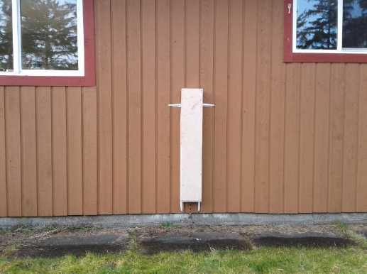
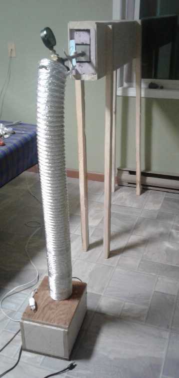
 Outdoor heat exchanger: Tall box on the outside
wall (same box), and duct and pipe
Outdoor heat exchanger: Tall box on the outside
wall (same box), and duct and pipe
through wall into house for incoming (warmed) and outgoing (still
compressed) air.
It seemed obvious that air compressors weren't being made
with heat pumping in mind. I thought about what an ideal air compressor
for heat pumping would be like.
Then I cut the first (water cooler) compressor apart with
an angle grinder and a hacksaw. It was immediately apparent that there
was a major bottleneck to the air flow, in the form of a 16 inch long
copper pipe of only 1/16" inside diameter. All my efforts to make the
airflow as free as possible once the air was out of the unit were
annulled by that.
I improved it by cutting off that pipe
and putting in a 1/8" one at the compressor body. That's 4 times the
cross section
-- and I only made that pipe 1/2 inch long before it "telescoped" out
into a
bigger one.
 Then I (finally) had a look at
the big new Makita air compressor. If it wasn't made for the job, at
least it seemed closer than anything else I had so far. It drew 550
watts with no air compression (drain valve open) which increased to
1100+ watts at 120 PSI. (Does that make it 50% efficient at compressing
air? Anyway it indicates at least 550 watts of energy (and probably
more) is going into actually pumping and compressing air, above and
beyond simply spinning the motor and oscillating the piston.) The
motor's fan also blew air under a shroud to cool the compressor, which
didn't get too hot while I had it running. If I made a large box and
put it inside, where a fan would blow its heat into the heating duct
(as with the fridge compressors), and attached the radiator pipe
directly to the bottom of the air tank, it should work better than any
other other unit I had.
Then I (finally) had a look at
the big new Makita air compressor. If it wasn't made for the job, at
least it seemed closer than anything else I had so far. It drew 550
watts with no air compression (drain valve open) which increased to
1100+ watts at 120 PSI. (Does that make it 50% efficient at compressing
air? Anyway it indicates at least 550 watts of energy (and probably
more) is going into actually pumping and compressing air, above and
beyond simply spinning the motor and oscillating the piston.) The
motor's fan also blew air under a shroud to cool the compressor, which
didn't get too hot while I had it running. If I made a large box and
put it inside, where a fan would blow its heat into the heating duct
(as with the fridge compressors), and attached the radiator pipe
directly to the bottom of the air tank, it should work better than any
other other unit I had.
But it had so much power
that it (surely) needed much more
radiator pipe, and surely I would have to install the outdoor heat
exchanger. And it needed a large new box with a fan on the side. I
wouldn't finish all that in February. So I tried
out my "improved" water cooler compressor first to see how it worked
and what lessons might be gained. It already had a box with a fan and
the fittings. All it needed was some pipe fittings and lots of PVC
("electrical") tape to close up the housing. It should last long enough
for an experiment of two. If eventually the oil leaked out and it
seized up... oh well. It was free.
I thought about the amount of power being used by these
various compressors. Ideally, if there was no radiator pipe or if the
end of the pipe was wide open, and no pressure would build up in the
system, the compressor is just blowing air like a fan. The duct fans
were drawing about 3-1/2 watts. Running with open ducts the compressors
started at 75 watts and went up from there to 750. (750 - one
horsepower - was for the
Michelin. The larger Makita was a little better at 550 W.)
This means that all the compressors are wasting huge
amounts of energy. Of course it takes some energy to turn a motor, and
to slide piston rings back and forth in a cylinder. But that should be
small, almost trivial compared to the energy needed to compress air,
where real work is being done.
One can literally feel the truth of this
when pumping up a bicycle tire with a hand pump. Disconnected or at no
pressure, the lightweight pump
handle, shaft and piston assembly plunges freely, almost effortlessly.
It may slide down the cylinder just from gravity. (Of course the more
pressure there is
in the tire, the harder it is to push the handle to the end of the
stroke to pump it up further because then it's doing actual work.) Why
do electrically powered compressors use so much power - or even any
significant amount of power - in free air?
One can see this is at least partly owing to internal
restrictions to the air flow: they are compressing air, but it is
decompressing before it even comes out of the compressor. Nowhere was
this more obvious than in the 1/16th inch, 16 inch long pipe in the
water cooler compressor. It was heavily compressing air in the cylinder
and making heat there regardless of whether the air outlet was wide
open or almost completely closed off. And thus the power consumed (75
W) didn't change much with external load, since most of the load was
internal. (After I put a larger pipe in, it used as
little as 55 watts pumping 20 PSI; 50 watts at 0 PSI.)
In a compressor designed for heat pumping, designed for
optimum efficiency, I would hope that the watts consumed would go up
with pressure by
a factor of 5 to 10 when pumping to it operating pressure. and also
that
much of the heat would go out in the air being pumped. The heat
starts in the compressed air. The "bicycle pump" air compressor with
effective (copper) radiator fins and a one-way valve would also be the
start of the radiator piping inside the opening of the duct, a
continuous solid copper finned pipe with no obstructions. (I am
presently thinking of how to make a "rotary" compressor using a screw
mechanism of some sort to move a rather large piston with a long stroke
in and out. That should have less vibration and noise than one with a
short crank arm flying
back and forth.)
In a test at the end of the month the outdoor heat
exchanger's performance was disappointing, raising the outdoor
temperature air barely half way to room temperature. It may need to be
made substantially longer to gain more heat exchange area between the
outgoing warm air and the incoming cold air. Or it needs to exchange
better over the same length. However, the performance was better than
without a heat exchanger. It really does seem to be a key component of
the system and I'm sure a better one will raise the COP. (I improved
it. It helped.)
On March 3rd I put together a configuration with the
larger fridge pump. The warm air came out the end of the heating duct 4
to 5 degrees higher than the room temperature instead of 2 to 3.
Drawing 115 watts it seemed to heat a little better than the 420 watts
radiant heater, suggesting a COP of at least 4. So the COP wasn't
higher but as the compressor was more powerful it was pumping more
watts of heat. But the temperatures at night weren't much above
freezing and it was quite inadequate for the amount of heat needed.
Time for the bigger compressor!
 As March started I had a pretty good setup with
the large fridge compressor in a box with a fan,
As March started I had a pretty good setup with
the large fridge compressor in a box with a fan,
finned pipes and a duct with air blowing through it, and the outdoor
heat exchanger, improved with
some thermal breaks in the copper pipes and some reductions to the
incoming air flow space.
(Here including a piece of foam partly blocking the inner opening in a
strong wind.)
When efforts are made to
create really high efficiency
equipment for air heat pumping, we will start to see the ultra-high
COPs dangling in front of us.
Another Higher COP Device
A reader sent me a link to another interesting device that
uses similar principles to get more energy performance out of heating
and cooling. This one is used to desalinate sea water. As well as
making drinking water at sea, this process will doubtless someday be
highly valuable for helping to turn deserts into fertile lands.
As best I understand the operation, the initial heat comes
from
the sun to vaporize sea water. But instead of simply letting the
evaporated water cool to re-condense, its heat in cooling and
condensing is used to heat more water up to near vaporization
temperature. Then (if I have this right), still pretty hot, it warms
the next 'batch' of water
part way. This is done, apparently in several steps, making it akin to
my outdoor heat exchanger using the heat of the outgoing air to warm
incoming air for the compressor. The water will be cool for drinking
sooner, too.
https://www.pv-magazine.com/2020/02/10/recycling-heat-for-a-385-efficient-solar-desalinator/
 February 10, 2020 Mark Hutchins
MIT scientists have developed a solar desalinator which transports heat
from the sun through a ten-stage process of evaporation and
condensation. The group estimates a $100 device employing their
innovation could provide the daily drinking water needs of a family.
Scientists at the Massachusetts Institute of Technology (MIT) have
developed a prototype solar-powered water desalinator which they say
achieved solar-to-vapor efficiency of 385% through a multi-stage
process where the heat released as water condensed was recycled,
flowing into the next layer to power the next stage of evaporation.
Rather than using photovoltaics to power electrically-driven
desalination - a method which has been used in large scale applications
already - MIT's process uses solar absorbers to gather heat from the
sun and evaporate the saltwater.
A prototype on an MIT rooftop delivered water which exceeded local
drinking water standards at a rate of 5.78 liters per hour, per square
meter of solar collecting area. The university said that was more than
double the previous record for water produced by passive solar
desalination. By optimizing and adding further stages to the
desalination process, the group estimates devices based on the concept
could reach efficiencies as high as 800% - meaning that eight times as
much energy as is initially collected from the sun would be available
for the conversion of water into vapor.
Nickel-manganate/Zinc Batteries
 An enthusiast
with casting equipment in Oregon is making
copper sheet electrodes with cast zinc on one face. This is likely
better than electroplating on the zinc. With the degrading zinc tabs
and
after the last very thin zinc sheet got holes in it, I think the copper
sheet is needed to make a solid, changeless base for the zinc which
oxidizes and reforms with discharging and charging.
An enthusiast
with casting equipment in Oregon is making
copper sheet electrodes with cast zinc on one face. This is likely
better than electroplating on the zinc. With the degrading zinc tabs
and
after the last very thin zinc sheet got holes in it, I think the copper
sheet is needed to make a solid, changeless base for the zinc which
oxidizes and reforms with discharging and charging.
He is sending me samples.
 I
also found
that in pH 13 electrolyte (even with salt in
it) cupro-nickel doesn't seem to degrade in the positive electrode, so
it can
be used instead of graphite for the current collector. That will be
better - yay! And monel or cupro-nickel powder can probably be used for
conductivity additive in the electrode. That too may be better than
graphite or 'acetylene black'
powder. Or better in conjunction with it.
I
also found
that in pH 13 electrolyte (even with salt in
it) cupro-nickel doesn't seem to degrade in the positive electrode, so
it can
be used instead of graphite for the current collector. That will be
better - yay! And monel or cupro-nickel powder can probably be used for
conductivity additive in the electrode. That too may be better than
graphite or 'acetylene black'
powder. Or better in conjunction with it.
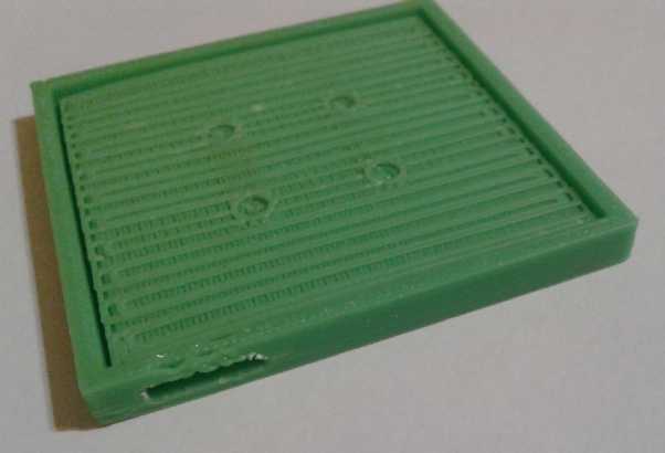 I designed a
50x50 mm flat cell case that would hold the
positive electrode compacted by having some glued support points in the
middle of a "porous" plastic separator as well as a glued-down outside
edge. (The nickel-manganate electrode is installed under the porous
grid with its tab sticking out the slot; the zinc electrode goes above
it. The sides will be a little taller, with an upper slot, an a cover
will be glued on top.)
I designed a
50x50 mm flat cell case that would hold the
positive electrode compacted by having some glued support points in the
middle of a "porous" plastic separator as well as a glued-down outside
edge. (The nickel-manganate electrode is installed under the porous
grid with its tab sticking out the slot; the zinc electrode goes above
it. The sides will be a little taller, with an upper slot, an a cover
will be glued on top.)
I still worried that a
thin
ABS grille is too flexible and will let the electrode swell and
lose contact with the current collector somewhat between the posts. But
on
line I found a new 3D printing filament: PVB. It sounds better -
stronger and stiffer than either ABS or PLA. (And unlike PVC, its
environmentally
benign.) Of course I ordered a roll to try it.
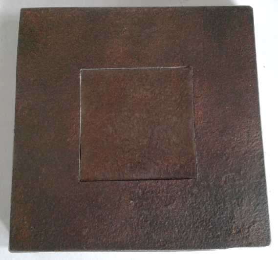 I
also made a very exact fit 50x50 mm electrode compactor
punch and die from 1/2 inch steel plate. After I put a base on it, it
should press good electrodes for my planned 50x50 and (eg) 100x100,
150x150 and 200x200
mm (by ~8 mm) flat cells.
I
also made a very exact fit 50x50 mm electrode compactor
punch and die from 1/2 inch steel plate. After I put a base on it, it
should press good electrodes for my planned 50x50 and (eg) 100x100,
150x150 and 200x200
mm (by ~8 mm) flat cells.
High Efficiency Titanium Dioxide Solar Cells and "Pebble" Surface
Cover Glass
[This probably belongs in some "detailed project report", but it's not
something I'm actively pursuing at this time.]
Longtime readers of this newsletter may recall that I did
some abortive experiments with dye sensitized titanium dioxide solar
cells a decade
ago. (eg, TE News #29) I was trying tartrazine (yellow food color) as a
dye. It has just the right light absorption spectrum. And I
developed a special glaze with a high refractive index (nanocrystalline
titanium dioxide borosilicate glaze). It could be ground up into a
"frit" (sandy grains) and melted into the front surface of solar panel
glass as little "pebbly" grains, tiny lenses that would aim angled
light more straight into the glass and hence increase the power gained
from light coming from steep angles and scattered sky light. I didn't
get that far.
Really
this was two separate solar cell projects both using titanium dioxide
and I
confused myself as to what I was doing and what my objectives were. At
the time I didn't even have any solar panels. If I had known where to
buy "raw" solar cells, I could have tried out the pebbly cover glass
idea separately with them, but at the time I didn't, and my TiO2 cells
weren't working. And it seemed more and more
like a lengthy diversion - wasn't I doing electric transport?
And as to titanium dioxide solar cells I thought, "So
what, even if they work?" I read about
the almost "problematic" tendency of titanium dioxide based solar cells
with liquid electrolyte
to leak. Could I solve that? And I had no shortage of other projects. I
threw up my hands for the time being, but I never got back to either
project.
Now some researchers have come out with "24% efficient"
titanium dioxide solar cells, a higher efficiency than today's
best silicon based cells and much higher than those being made at the
time I was experimenting. I hadn't realized the potential of TiO2 for
actually
being significantly better than silicon, or I might have continued.
Probably a non-liquid electrolyte that would work could be (or has
been) found, too.
First: Cover Glass (In)Efficiency:
In an article in PV Magazine, researchers studied the effects of
creating microfractures in glass to assess how they deteriorated panel
performance. It shows that the surface
of the glass is important.
https://www.pv-magazine.com/2020/02/17/assessing-the-impact-of-micro-cracks-in-solar-glass/
 By deliberately stressing
glass to simulate years of wear and weather exposure, and with all
other factors being the same:
By deliberately stressing
glass to simulate years of wear and weather exposure, and with all
other factors being the same:
"The Turkish team ascertained reduction in both exergy and energy
efficiencies were attributable to a large number of micro-cracks
and
deformations on the glass surfaces, which were responsible for
considerably affecting the absorbance, transmittance and reflectance
properties of the materials." [my italics]
Those little pits and cracks, causing reduced performance, appear to
affect performance pretty much
the opposite of what I hoped to achieve with the convex 'pebbly'
surface. Those little lenses would aim angled light more directly onto
the
active
collector surface, whereas pits would do the opposite and cracks would
also scatter the light.
Well, I still have the formula and method: TE News #29,
June 2010, "Glaze Mix 9". I also still have no shortage of other
projects. Solar panels are a big industry. It would be one more
exciting thing that could be developed
and commercialized if there were some more people in on the act.
Second: 24% Efficient Dye-Sensitized Titanium Dioxide Solar Cells
https://www.pv-magazine.com/2020/02/13/a-titanium-solar-cell-with-24-efficiency/
In 2010 silicon solar panels were maybe 12% efficient. Now
they have hit and passed 20% efficiency in the best new panels. But if
a solid electrolyte is or has been found, dye sensitized TiO2 panels
might still be
cheaper and easier to make and are said to be more environmentally
friendly.
With higher efficiency, fewer solar panels need to be
installed, reducing the materials and installation costs for putting in
solar energy. A typical house roof that might today be covered in about
as many panels as it can hold might be only 2/3 full instead, or if
filled would supply more energy.
The Australian research team which developed the device said the higher
efficiency was achieved through a nanowire design which eliminates the
interface
inside the titanium dioxide band.
['interface': usually a transparent, conductive tin-antimony oxide
"current collector" layer behind the glass - but in front of the TiO2.
In my trials I was having trouble getting a good layer.]
February 13, 2020 Emiliano Bellini
Titanium dioxide forms the basis of the cell, with efficiency lifted by
a nanowire structure.
 A delicious looking dish of titanium dioxide
nanopowder accompanies the article
A delicious looking dish of titanium dioxide
nanopowder accompanies the article
Scientists at Australia's Queensland University of
Technology have developed a quantum dot, titanium dioxide (TiO2) solar
cell they claim offers better efficiency more cheaply than traditional
crystalline silicon cells, as well as being more eco-friendly.
The researchers claim the cell boasts 24% efficiency, more than double
the 8-11% lab-level performance observed in standard TiO2 quantum dot
devices.
Some photons become trapped in the interface between nanocrystals in
typical TiO2 quantum dot cells but the Queensland team claim to have
removed the problematic interfaces.
"Our nanowire design eliminates the interface inside the
TiO2 band, as it's just a single layer of QD [quantum dot]
-coated TiO2," said research coordinator Ziqi Sun. "If we can remove
this disordered interface, we can
improve efficiency."
Commercial production
The nanowire crystal used for the cell was assembled in China with an
advanced transmission electron microscope.
The research group said their cell concept could be expanded to bring
the technology to production.
Most dye-sensitized - Grätzel - solar
cells are based on titanium dioxide thin film - a cheap
and harmless, water-insoluble inorganic material which is commercially
available and widely used in industrial applications.
Low efficiency has remained the chief obstacle preventing such
materials competing with crystalline silicon cells to date.
Titanium has also been used recently to raise the efficiency of
perovskite cells. Research projects of that nature have been carried
out by Japan's Kanazawa University and scientists from
Russia's National University of Science and Technology and
Rome's Tor Vergata University.
And maybe some solid electrolyte can be (or is being) employed to
eliminate the
leakage problem. There would be a pretty rapid switch to this type of
panel if it was available, cheaper, reliable and anything like 24%
efficient.
(What efficiency might I have achieved if I had kept working on it?
These people have a much better idea of what they're doing and some
fancy equipment. But I still suspect tartrazine would be the best dye.
Might it boost efficiency even farther?)
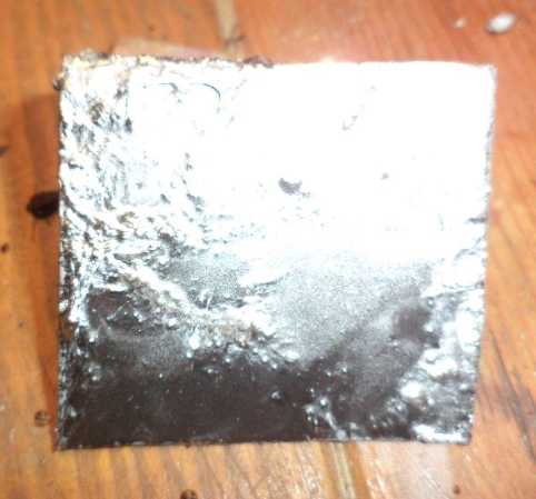
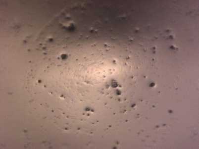
NiMH D Cell Refill
 Finally, here
is a picture of the long dead nickel-metal hydride battery I cut the
top button off of, drilled through a rubber seal beneath it, and
refilled with some distilled water (amount not measured). (as mentioned
at the end of January in the previous issue) It then took a charge -
but didn't seem to hold it overnight. Some cycling might or might not
help, but I didn't get around to doing anything more with it.
Finally, here
is a picture of the long dead nickel-metal hydride battery I cut the
top button off of, drilled through a rubber seal beneath it, and
refilled with some distilled water (amount not measured). (as mentioned
at the end of January in the previous issue) It then took a charge -
but didn't seem to hold it overnight. Some cycling might or might not
help, but I didn't get around to doing anything more with it.
NiMH cells are known to corrode if their voltage sits at
less than 1.0 volts. Since this one had sat for probably over two years
completely dead and discharged, one suspects that refilling cells that
aren't completely dead yet, but which have become reduced in capacity
owing to drying out inside, would probably work better - perhaps even
restore them completely.
In Passing
(Miscellaneous topics, editorial comments & opinionated rants)
Permian Period
Amphibian Evolution (continued)
* It seems the earliest fossil eggs that
have been found were from the Triassic period (and the earliest egg shells
are from the Jurassic - so Triassic eggs must have been leathery
covered?). This has puzzled paleontologists: "One of the fossil
record's most puzzling features is the absence of preserved eggs or
eggshell of the first third of the known 315 million year history of
amniote evolution."
This is in fact excellent further support
for
my theory that there were no
reptiles before the end of the Permian period. I believe that the
creatures on
land until the Permian extinction were actually (adult) amphibians (not
amniotes) or an intermediate stage, "pre-reptiles", which have long
been misidentified
from the meager fossil remains as reptiles (or even "mammal-like
reptiles", their anatomy being atypical for reptiles). The present view
that reptiles - advanced
land life - crawled out of the sea almost contemporaneously with
amphibians - fish that later breathe air in adulthood - in the mid
Carboniferous, long before there were seed bearing land plants to
support an advanced land ecosystem and even before all the carbon
dioxide
had
been eliminated from the atmosphere (and deposited as coal), on the
face of it actually
seems pretty far fetched. It probably didn't in earlier times before
the great anatomical differences between amphibians and reptiles were
well appreciated, and in that ignorance the error was originated. (See
TE News #100)
Small Thots
* I had my hair cut short, virtually shaved off, and I discovered
perhaps what it is that may be the advantage to that for keeping or
perhaps restoring thinning hair: when you rub your scalp, you're often
pushing
the short bristles into the follicles instead of merely pulling at
them. Furthermore, you're moving them around in different directions
than with your usual hair style.
Anyway that's what I've come up with for differences very
short hair makes.
And I don't know what if anything it has to do with the demodex
follicularum mites or any damage they may have caused to the scalp and
hair follicles. (It's hard writing a coherent piece on this when the
ideas or answers come in so much piecemeal, over months and indeed
years.)
* It seems Joe Biden is having a lot of trouble just making coherent
sentences these days. Senile dementia has well set in. In choosing this
near zombie, under criminal investigation in two countries, as the next
"Democratic"
party presidential candidate, the corrupt body politic is clearly
showing it wants only a figurehead in the highest office, someone who
will
obligingly rubber stamp whatever they've decided on out of public view.
They've had far too much trouble getting that out of the current
occupant, and they've had a lot of trouble getting some of the other
candidates with their own programs and ideas off the stage. (Not with
the reasonable, honest candidates with sound ideals and sane ideas.
Those are easily disposed of. Tulsi who? She got the mic? Well, just
cut to a political commentator while she's speaking.)
ESD
(Eccentric Silliness Department)
* When is Obsolete Obsolete? It's been 2000 years since people
were
using plumbium (lead) for water pipes. Why do we still call them
"plumbers"? Enough is enough already! Shouldn't they be called
"copperers"
or "pexers" or something?
* Stragedy: A dyslexic's cunning plan that ends up very badly.
* People in China are spraying disinfectant on bank notes, or boiling
them. As the Wuhan corona virus spreads, people all
over the world will soon be laundering money.
* "I must be an athlete... I have an athlete's build... athlete's
reflexes... athlete's foot."
* Lettuce not beet about the blueberry bush. If we really carrot to
help our fellow human beans, we would have mustard up the curry to
chervilly collard up the scallions in our legislatures and insist that
they turnip their efforts for those with who have been uprooted, those
sorrel cases
who have leeked through the cracks, to help them ketchup
with the rest of us. Then there can be peas for olive us. (Vegetable
stew for dinner?)
* Biologists know that nothing in life is unavoidable except death and
taxonomy.
* The Americans invaded Syria and Afghanistan and have long been
threatening Iran. I believe I have finally figured out what they're
really after: Pistachios! They are native to these countries, and
especially Iran. If they can dominate them like they do Latin America,
and turn them into "pistachio republics", then these delicious but
costly nuts can be much cheaper in the USA. No wonder they have wanted
Iran so
badly for so long!
"in depth reports" for
each project are below. I hope they may be useful to anyone who wants
to get into a similar project, to glean ideas for how something
might be done, as well as things that might have been tried, or just
thought
of and not tried... and even of how not to do something - why
it didn't
work or proved impractical. Sometimes they set out inventive thoughts
almost as they occur - and are the actual organization and elaboration
in writing of those thoughts. They are thus partly a diary and are not
extensively proof-read for literary perfection, consistency,
completeness and elimination of duplications before
publication. I hope they add to the body of wisdom for other
researchers and developers to help them find more productive paths and
avoid potential pitfalls and dead ends.
no reports
Other
"Green"
Electric
Equipment
Projects
End
of
Kitchen
Solar
Hot
Water
Tank?
(8th) With my mineral-rich well water, for whatever reason, once the
water had sat in the tank under the kitchen sink for a day or two, it
started to stink. A
sulfur smell permeated the air near the sink whenever hot water was
run. Or maybe it was straight hydrogen. I am puzzled as to why this hot
water tank would smell when the large tank has always been fine,
however long the water sits in it.
Other than that I had been very happy with the 15 liter,
36
volt water tank. I had hot water in the sink in 2 or 3 seconds, as hot
as I cared to set the thermostat to. But the stench was too much, and I
couldn't figure out why it was there or how to get rid of it. (Now I
think some mineral was causing the water to react with the tank metal,
to oxidize it
and bubble hydrogen. There was a lot of black sludge in the tank when I
removed and drained it. Or maybe it formed hydrogen sulfide. Apparently
it's a very common problem where there is mineral rich water.) I
just couldn't run a whole tankful of hot water every day to keep it
fresh. Even keeping the tank cold didn't entirely solve the problem,
tho it seemed to slow it down.
Finally I ordered a 3KW "on demand" water heater. This
huge draw just while the water is running - the total of all my solar
panels at noon on a sunny summer day - is the opposite of what one
needs with off-grid type solar power - something that can collect heat
gradually all day so it's there to be suddenly drained when you want
it. Well, I'm not off-grid as long as there's a grid.
Now I finally got
around to installing it. I picked 3 KW, the smallest power available,
because there was an electric
heater under the sink at the floor (which I had never used - I only
finally turned
it on to find out which circuit breaker it was on.) and I could (and
did)
take the 230 volt #14 AWG cable from that to use for the water heater
instead
of having to run new, heavier wire all the way from the breaker box.
I am not enamored with this unit. One must run the water
quite slowly to get it warm, it takes 20 or 30 seconds before hot water
is coming out, and I would never really call it "dishwashing hot"
except at the lowest dribble of flow rates.
Well, it did say it was for a "lavatory sink".
One major impediment was that the outlet to the hot water
faucet was at the bottom left facing down, and I had to put in a 16
inch long "U" of copper pipe with several odd fittings I had (a
frustrating piece of
plumbing) to aim it up and bring it close enough to reach the already
long (18"?) flex pipe to the faucet, which then had a further 18" spout
on it (a tall upside down "J" spout). What was especially galling was
that the hot water came out of the heating element at the top of
the unit, and there was a foot-long pipe inside bringing it down to the
fitting in the most inconvenient possible spot, the bottom left. Since
the hot water lever is usually the one on the left, in order for the
heater to be clear of the cold water pipes it will normally be mounted
on the wall under the left side of the sink. Thus the shortest run in
most situations is obviously from the top right, and just as obviously,
with the very limited flow and "on demand" heating, the run length is
very
important. I suppose they had leaks and electrical safety in mind, but
after installing and using it I can see that the setup is ridiculous.
They should have simply brought the output pipe outside the case to the
top right (even closer!) and had the join away from it.
It all made a total of almost 6 feet of piping between the
"on demand" heater right below the sink and the end of the spout. With
the tiny flow
available to get really hot water, it takes quite a while to actually
get hot water. If you run it faster, it never gets very warm. If I had
used some skinny tube instead of 1/2 inch pipe
it would have helped. But it would have been far better with the hot
water outlet at the top on the right to allow the shortest connection
to the faucet instead of forcing one to do a lot of extra work to
create a very long one. To get decently hot water, one only cracks the
tap open a little - and waits, and waits - and then if it isn't on
quite high enough, the unit doesn't
turn on and the water stays cold and all the waiting is in vain.
I'm tempted to disconnect everything, take it out,
disconnect the fitting, cut most of the pipe off, and try to bend it up
to join straight to the flex hose at the top. (I've been doing lots of
that sort of thing for the air heat pumping!) That would cut out about
2 feet of piping and so reduce the absurd wait for "on demand" warm or
hot water. In fact, then I could put in a shorter flex pipe, too, and
make it 2-1/2 feet less.
Six kilowatts would obviously not by any means be overkill
for an "on demand"
kitchen sink water heater - I would now judge it as minimal. I think a
shower or
bath would take more - 12 kilowatts?
But the water doesn't stink.
Hot Water Tank Protective Anodes
(10th) Now that I've gone to all that work - removed my under-sink tank
and installed the "on demand" hot water unit - I see on youtube that
there's something called a sacrificial anode in hot water tanks! A guy
showed four hot water tanks cut wide open with a zip disk/angle
grinder, and there they are: rods sticking down from the top.
Apparently they're magnesium or aluminum and by corroding first, they
protect the metal tank from rusting! How is it possible I have lived
this long, and even having replaced several water tanks, I've never
heard of them before? How is it possible people say a tank lasts 8
years (or whatever) and never mentioned that there's an anode inside
which eventually wears out and then stops protecting the tank? Or is
putting an anode in water tanks a "new" idea that I just never heard
about -- like newer than the 1980s when I was (too frequently)
replacing hot water tanks in my old house? I'm going to guess that
that's the case, since my last water heater lasted 19 years 11 months.
(I remember it because of something else at the time I replaced it,
December 1996. It sprung a leak in November 2016 before I moved and I
was cursing that it hadn't lasted just a few more months until it was
somebody else's problem! Probably it had needed a new anode and with
one could have lasted more decades yet! No doubt I should check my
present main water tank.)
I'm
going to guess that in my mineral rich water the anode wore out quickly
and that's when the water started to stink, because I don't remember it
smelling until it had been installed for a while. When I removed it I
unscrewed a nut attaching a bolt through the shell (whose purpose I had
wondered
about), and something fell down inside. No doubt it was the anode. In
this small tank it wasn't made to unscrew from the shell and pull out
the top. I would have to unscrew the heater element to access the
inside and really see what's up. Sometime I will get to that...
Simple
Air
Compression
Heat
Pumping
- or -
How to Heat a Building Almost for Free
I read on a "Q & A" discussion list ("Quora") that air
heat
pumping does work, but "at low efficiency" and needing to pump "quite a
high volume of air at high pressure". I understood it was lower
efficiency, but with potential Coefficients of Performance (COPs) being
so high in the open loop air system one should be able to tolerate
quite poor efficiency and still get excellent results.
And having now looked at and tried some compressors, I
think the low efficiency is in the way compressors are being made and
not
inherent in the whole process. Today's air compressors are simply not
designed for heat pumping and they care nothing about design as related
to
that purpose. Just thinking of the simplicity and efficiency of a hand
bicycle pump one can see that it's easily possible to do much better.
(3rd) With Water Cooler (Refrigerator Type) Pump
 The water cooler compressor blew up a balloon
very slowly
The water cooler compressor blew up a balloon
very slowly
I unsoldered the inner 'telescoping' narrow pipe from the
larger
output pipe on the 'new' refrigerator compressor to leave a maximum
size opening with least resistance to air flow. It was a hard go,
heating virtually to red hot - must have been silver solder. I tried to
do the same with the input pipe, but the whole thinner pipe softened
and fell off without melting the solder. I cut it off shorter. A last
bit of the intake's thinner pipe was then loose inside and came out.
I note that when I first plugged it in, it sprayed out
some oil. Later I turned it sideways and more oil started dripping out
the input pipe. So it still had some oil in it. (several fluid ounces
as it turned out.) I suppose it will need
occasional or even frequent lubrication now that the oil isn't sealed
inside with the refrigerant.
When covered and turned on it also pinned my 0-60 PSI air
pressure meter in about one second!
I
went to put it into the heat pump box box and found it
was 3/4" too tall. I had to rebuild the box. I filed a pipe with 1/8"
NPT threads on one end for a
friction fit over the compressor's output pipe. I threaded another
fitting I had, to screw onto it and bring it up to 3/8" NPT to fit
another adapter to the 1/2" copper water pipe size. (In 35 years I
think that's the first time I've ever used that threading tap! But
there it was in the set. The trick with NPT threads is that they're
tapered. One must taper the end of the pipe slightly with a file,
grinder or reamer before trying to thread it. Even lots of pro metal
workers don't know that and can't figure out why it won't thread. But
it's why pipe thread joints don't leak.)
 (4th) I bought
a 0-160 PSI air pressure meter. I worried about setting
a 4 foot long heavy finned pipe on top of the soft, scrawny copper
output pipe on the fridge compressor. It would just bend it and fall
over, and probably kink it. I thought the least I could do was put a
steady of some sort on the pipe. It would have been easy if the air
duct didn't have to fit over the pipe and also into the hole in the
box. I cut a chunk of aluminum and rigged something up. Afterward I
thought of a better arrangement. I'll probably want to make that later,
so there's no force at all pushing on the fridge compressor's little
output pipe.
(4th) I bought
a 0-160 PSI air pressure meter. I worried about setting
a 4 foot long heavy finned pipe on top of the soft, scrawny copper
output pipe on the fridge compressor. It would just bend it and fall
over, and probably kink it. I thought the least I could do was put a
steady of some sort on the pipe. It would have been easy if the air
duct didn't have to fit over the pipe and also into the hole in the
box. I cut a chunk of aluminum and rigged something up. Afterward I
thought of a better arrangement. I'll probably want to make that later,
so there's no force at all pushing on the fridge compressor's little
output pipe.
(5th) I
changed the outdoor heat exchanger from 2 legs to 4. (Then I
had to unscrew 2 to get the height just right for the other pipes.) I
put everything together and turned it on at 21:00 PM. Now it wouldn't
go above 30 PSI. Why did I buy a new air pressure meter again?
I closed the doors and turned off the LED garden lights (~200W). It
started off with the following conditions:
Outdoor air: 2.5° (°C), no wind.
Room air (at kitchen table) 17.6°
Cold air in at floor: 16.0°
Air pressure in pipes: 20 PSI
This time the compressor was so much quieter that the air
fan was most of the noise. It makes quite a whir, but with the lab air
pump I could hardy hear it, and not at all with the Michelin
compressor. A very slight waft of cool air could be felt coming in the
outdoor heat exchanger. Also unlike other tests, the compressor and its
output pipe seemed hardly warm. Then I put my hand near the pressure
meter and felt a leak at a soldered joint. I wrapped some electrical
tape around it. But the threaded joint next to it was also leaking. I
turned it off and 're-threaded' the pipe with some new teflon tape, and
while I was at it I put the old lower pressure meter back on. I turned
it back on. It seemed no matter how much tape I wound around the leak I
couldn't stop it. But it was now next to nothing.
Soon the warm air out was 19.3° (instead of
18.3°), almost 3 degrees warmer than the 16.5° air being drawn
in by the fan at floor level. That had to be doing some heating. Later
the temperatures were down a bit (disappointing but not surprising
given it was 2° outside.) Warm air 19.1, Floor air back down to
16.0, and the room air 17.1. I went in and did some dishes and they
came up marginally - about .2 degrees - a warm human, hot dish water
and vapor.
At 23:00 PM I finished and I turned off the pump and fan.
Within 15 minutes the temperature was down 1/2 a degree, and .7 or
.8° in half an hour. The heat pump had definitely been doing some
good pumping to keep it from dropping much for two hours. Then I went
to run the 425W electric heater for 1/2 an hour, but the temperature
rose .4° in a very few minutes - in fact, when I turned the heater
on and looked again it was already up by .1°. Perhaps I had left
the livingroom door open for a few minutes? Or maybe it was because the
fridge had come on? Then after I left the room the loose "tip over"
switch decided to cut the heater off and the temperature dropped. I
decided to ignore that test entirely and run it another 1/2 hour. The
thermometer read 16.9° the whole time until just before 00:30 it
went up to 17.0. At that time I turned it off and turned the heat pump
back on.
I put my hand on the tape and managed to squeeze off the
leak. It didn't seem like much, but the air pressure rose from 35 PSI
to 46. That was surely a substantial loss, having that air
decompressing into the room instead of outside. It was too late at
night to stop and fix it. Manñana! The temperature dropped a bit
over 40 minutes by 01:10 AM, but not as much as with no heat. or with
just 75 watts of it.
(6th) In the morning I returned to the charge. I re-soldered the pipe
fitting and put it together again. An hour later, thinking I still
heard hissing air, I found another leak, inside the box. It was hard to
get into and I had only tightened it by hand. (There was oil from
inside the compressor all over the fitting.) I took the wall with the
fan off the box and got two wrenches in and tightened it up. The
compressor motor outer case was just a little warm. It seemed the heat
transfer
was very good, especially compared to the previous compressors. I was
now running it at about 45 PSI. It seemed to be getting the room slowly
warmer. Then I realized a window was open 1-1/2 inches for fresh air
and I closed it.
It was quite something, because nothing much seemed to be
happening. What heat? There was noise, and a fan was blowing cold air
out the end of a dryer hose duct. How could that heat a room? Yet that
air was a couple of degrees warmer than the air coming in at floor
level and just a bit warmer than the temperature of the room, and would
continue to be a bit warmer than the room regardless of room
temperature. A low temperature rise is just what is wanted for high
heating COP. I went away for an hour and the room temperature had risen
by about 1/4 of a degree. That would make it about the equal of the 425
watt radiant heater... except that the outdoor temperature had risen to
5.5° and the LED lights (200w) were on. (Too many variables!) At
13:45 I turned the unit off, but at 14:00 (for once) the sun came out,
heating the room through the patio doors and making further comparisons
of temperature changes useless.
Here are some typical readings, obtained in the evening
after running the unit for a couple of hours:
Outdoor air: +2° (dropped from +5° earlier)
Room air: 17.3° (at table height - livingroom door was open
allowing woodstove heated air in, so this temperature is meaningful
only in comparison with the two below.)
Cold air into duct: 16.1° (room air at floor level)
Warm air out of duct: 19.1° (so the air was being raised by
3.0°, to 1.8° above room temperature, as it blew through the
box and duct past the compressor and stegosaur pipe. With a faster fan
it would have been even less rise - but at least as much heat.)
Top of Pipes°: not measured in this instance. (It seemed to be
typically only 1/4 of a degree above the warm air temperature, so it
would seem the "stegosaur" radiator pipe (now with about 30 inches of
fins) was quite effective, and or that the pipe wasn't being warmed
very fast by the mere 75 watt compressor.
Compressor Body°: Not measured, but felt like 35+°. (Here is
where there may be some important losses and COP drop.)
Pressure in pipes: 44 PSI
Pump power: 72 watts (Varied from ~78W cold to ~72W once well warmed)
Duct Fan power: 3.2 watts
Means for Improvement?
This time I didn't see (feel) any major "hot spots" on the
compressor where the pumped heat is being wasted. But it was definitely
warm, and there may still be one or more bottlenecks inside the outer
body of the compressor. The real compressor flops around inside when
you tip it, "clunk clunk", so it's obviously just a
refrigerant-leak-proof outer shell that's seen. (It probably cuts down
the noise quite a lot.) Does it restrict air flow? I suspect something
in there is reducing efficiency. (It sure was!) If I get up the nerve,
I may cut open
the compressor body and see what further gain might be had by using
just the actual bare bones compressor from inside the housing. Actually
I think I'll get another one to do that to.
Also I'm not sure how effective my outdoor heat exchanger
is. With the small compressor there's almost no air to be felt coming
in through it, and what it does need may be coming in through other
leaks in the room. One of the doors, a sliding door to a very cool room
with lots of free air flow, has big gaps under it and on the side. It
could draw air through that perhaps more easily than through the heat
exchanger. If this is in fact the case, an effective COP rise - and
some air definitely coming in through the exchanger - might be observed
in a tighter space.
I've heard it said that plain air heat pumping is less
efficient than with refrigerant. No doubt that's why everyone has gone
with refrigerant until now. But reducing the pumping 'lift' required
from 20 or 30 or 40° (depending on weather) to 10° and maybe
even well under that (independent of weather), makes allowances for
even very low efficiency of equipment and technique to nevertheless
attain high real COPs.
If the 75 watt air compressor only does about as well as
the 425 watt electric heater, that indicates an effective COP of about
5.5. Or it may be a bit less. Even if COP 20 or 10 can't really be
attained in practice, at least not without a specially made air pumping
unit, 5 or higher (no matter how cold it is outside) is still better
than anything else out there. I can replace the 250/500 watts radiant
heater in the travel trailer with the 75 watt heat pump - 1.8 KWH per
day to keep it from getting cold and mouldy* instead of 6 or 12 (and I
won't care about the noise). But I'm sure that if I can't improve them
myself at home, once this goes commercial great efforts will be made to
attain those juicy potential COPs.
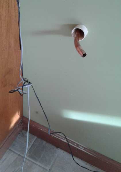
 At one point I thought to check the temperature of the
decompressing air at the nozzle outside. It was 4.0°, while the
outdoor temperature was 2.2°. The fact that it was about the
outdoor temperature instead of below indicates the outdoor heat
exchanger wasn't doing well. I'm pretty sure the compressor had an
easier time drawing in air from elsewhere, as one couldn't feel much
air movement coming in from the exchanger. However, 4° is way
colder than the radiator pipes it was coming from. The unit was
definitely compressing and heating the indoor air, and decompressing
and discharging it outside much cooler.
At one point I thought to check the temperature of the
decompressing air at the nozzle outside. It was 4.0°, while the
outdoor temperature was 2.2°. The fact that it was about the
outdoor temperature instead of below indicates the outdoor heat
exchanger wasn't doing well. I'm pretty sure the compressor had an
easier time drawing in air from elsewhere, as one couldn't feel much
air movement coming in from the exchanger. However, 4° is way
colder than the radiator pipes it was coming from. The unit was
definitely compressing and heating the indoor air, and decompressing
and discharging it outside much cooler.
That the leaks in the house were drawing in a bit of cold
air only added a bit to the heating load. They didn't negate the
overall heat pumping effect. (hmm, a couple of windows at the far end
of the house were cracked open for fresh air.)
*On the 5th someone living 'off grid'
told me a horror story of how his
unheated travel trailer quickly got damp and went mouldy inside, and
became unlivable and useless.
New & Improved Compressor
(8th) I went
back to the refuse transfer station and got another fridge
compressor. This one was from a large fridge instead of an office water
cooler.
(9th) It seemed to put out far more air. It was around 100
watts running open, but if one covered the air outlet, it quickly ran
up to 150 watts and even 185, and plenty of air really wanted out! My
immediate impression was that it was far superior to the other one.
Twice the power and more, and seemingly at least 10 times as much air.
And it even was quieter! The power of the other one stayed pretty much
constant at 75 watts regardless, while this one changed markedly if it
had to compress the air more, indicating that its power was being much
more fully harnessed to the work, not just into turning itself.
This one was taller yet than the first and second ones and
bigger around, so I would have to rebuild the box yet again with more
changes. I decided to leave the present box and make a new one. Making
and assembling 6 plywood sides into a box took the afternoon.
I went to dinner at Mike & Heather's on board their
boat. Mike was replacing the heating system on a neighboring boat and
gave me two four foot radiator pipes of 3/4" copper with aluminum fins
from the old system being discarded. What a great score! That would
save me from having to make a bunch more stegosaur radiator pipes
before trying out the new compressor - I was sure it would need more
radiators than the old one.
A parameter I thought of later was that the pipes might be more
effective per foot if there were heat exchange fins inside the
pipe so the compressed air would yield its heat more readily to the
copper pipe. How much improvement that would make I have little idea,
but it sounds hard to do. Perhaps here is a place for aluminum: short
lengths of 'fin assembly' can be inserted and pushed into the pipe with
a plunger of some sort until it's as full as desired. OTOH might it be
noisy with compressed air running by little pieces inside? It seems to
have enough hiss going around a sharp corner that I ended up making the
corners rounded.
New Heating Unit
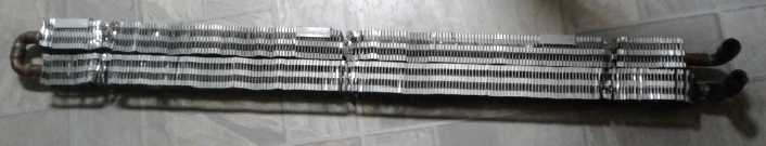
12 foot finned radiator pipe
 (16th) With
these new components I got a couple more pipe fittings and
another piece of dryer duct and started putting together a new unit.
Since the 9th I had unsoldered the two new finned pipes and reassembled
them in line so I could get the dryer duct over them. And I put in a
pipe union and added the stegosaur. I had enough confidence to drill an
11/16 inch hole through the house wall so the compressed air radiator
pipe would end outside.
(16th) With
these new components I got a couple more pipe fittings and
another piece of dryer duct and started putting together a new unit.
Since the 9th I had unsoldered the two new finned pipes and reassembled
them in line so I could get the dryer duct over them. And I put in a
pipe union and added the stegosaur. I had enough confidence to drill an
11/16 inch hole through the house wall so the compressed air radiator
pipe would end outside.
It seemed to me at the time that the outdoor heat
exchanger didn't really
do a lot, and I didn't bother with it for this build. The compressor
just didn't draw that much air, and it seemed to get it from other gaps
anyway - windows cracked open or whatever.
 Now I fitted out the
plywood box and mounted the
compressor and another fan in it. After I mounted the fan it occurred
to me to wonder whether it should blow air from the compressor end, or
from the far end and then through the compressor. If it blew from the
compressor end the unheated air would hit the compressor and the
warmest part of the radiator. But then it still had to blow it out the
far end. That meant that warmed air would hit the coolest end of the
radiator pipe, and it might not cool it any further.
Now I fitted out the
plywood box and mounted the
compressor and another fan in it. After I mounted the fan it occurred
to me to wonder whether it should blow air from the compressor end, or
from the far end and then through the compressor. If it blew from the
compressor end the unheated air would hit the compressor and the
warmest part of the radiator. But then it still had to blow it out the
far end. That meant that warmed air would hit the coolest end of the
radiator pipe, and it might not cool it any further.
If on the other hand the air blew the other way, the
coldest air would hit the coolest end of the pipes, and the pipe would
be coolest when it when outdoors and hit the end. The somewhat warmed
air would flow past the warmest end of the pipes and the compressor.
And the warmer air would come out at floor level where the fan was
blowing it out.
I decided the second way was better. That seemed
convenient, because I had accidentally mounted the fan on the wrong
face of the plywood - on the outside. Now I wouldn't have to turn it
around. (I may put it inside it later.)
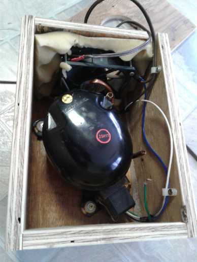
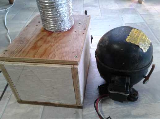
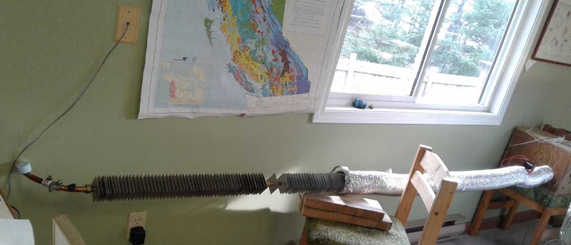
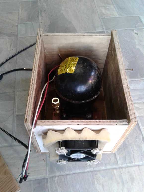
 The larger fridge compressor in its
box and all connected, fan pulling out
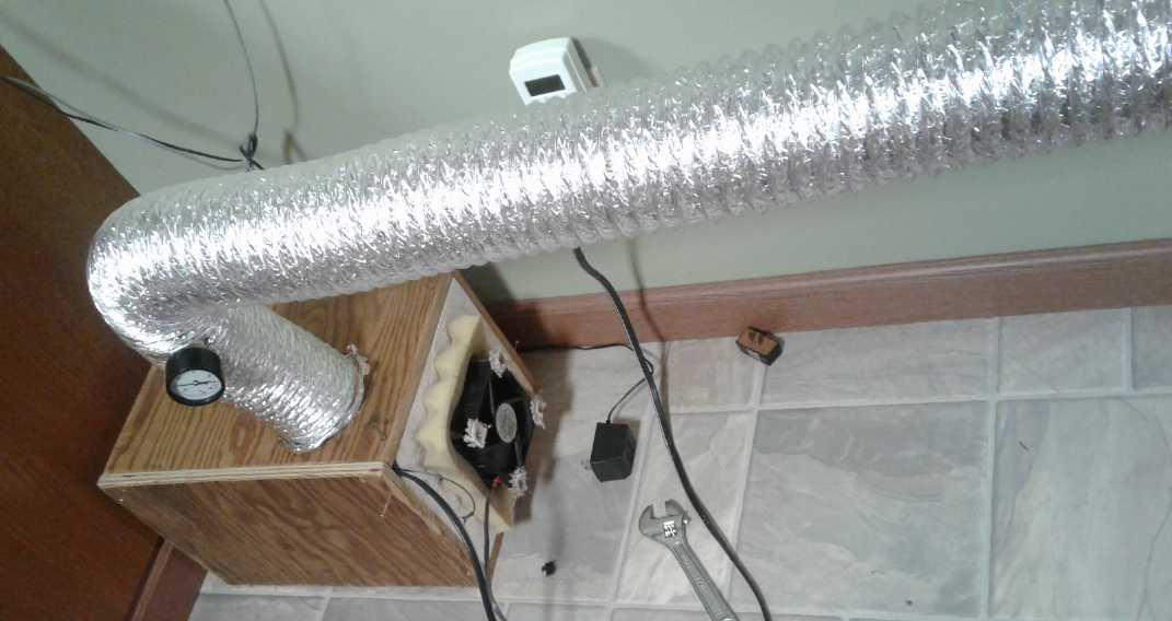
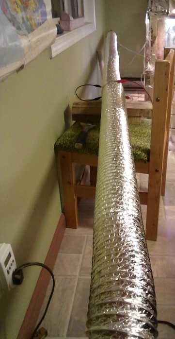 (17th, 18th) I got
everything together and fired it up. It didn't seem
to perform very well. The warm air out wasn't even as warm as the
smaller compressor. I thought that since warm air rises it might
circulate more slowly because of being pulled down instead of pushed
up. Later I remembered that the uninsulated aluminized duct was now 15
feet long instead of 5, and that warmth would be radiating from it all
the way along. So the air at the end should be cooler.
(17th, 18th) I got
everything together and fired it up. It didn't seem
to perform very well. The warm air out wasn't even as warm as the
smaller compressor. I thought that since warm air rises it might
circulate more slowly because of being pulled down instead of pushed
up. Later I remembered that the uninsulated aluminized duct was now 15
feet long instead of 5, and that warmth would be radiating from it all
the way along. So the air at the end should be cooler.
Still, it didn't seem to be warming the room very much.
Again it seemed less effective than the 420 watt electric heater. Why?
(19th) I turned the fan around. Then I turned up the air pressure from
60 to 80. (actually from 63 to 77, by closing the faucet on the outside
end the the pipe a bit more. It's hard to set exactly.) One or both of
these measures seemed to help. Temperature readings including room
temperature slowly started rising.
There was a join between the two sections of dryer duct,
and I had closed it with alligator clips. I could remove one and put
the temperature sensor in there. It was at least a degree warmer than
at the warm air outlet, proving that a lot of the heat radiated out
before it reached the far end.
I ran the unit for about 6 hours. Initially it warmed the
room a little, but it failed to get it above about 16.5 degrees at any
time. This was however the warmest part of the house as I had tried to
do something with the woodstove and then it smoked horribly. (I had to
wait for it to pretty much go out so I could take the stovepipe off.)
After that I ran the 420
watt radiant heater for a couple
of hours. Once again it seemed to do about the same as the heatpump or
maybe a little better. The good part was that the heatpump was 120
watts where the radiant heater was 420, suggesting a COP of at least 3
to 1. This at least seems to indicate that
open loop air heat pumping works and is worth pursuing - it can save
energy and money over simple electric radiators, and the performance is
on a par with refrigerant based heat pumps but it's simple to install
and cheaper.
Along the way I noted that fridge compressors seem to burp
oil out the compressed air outlet. I thought it would drain back inside
since the outlet air pipe goes up, but even when it's turned off, the
oil just sits and builds up in the pipe. It burbles more and more the
longer it has run. One might drain it, but of course the compressor
eventually needs the oil.
So apparently, to accommodate in an open air system this
type of compressor, which is made to run continuously and last a long
time but in a closed loop of refrigerant, it needs a very tiny
connecting pipe to bleed the oil back into the air inlet and hence back
into the pump. Ug! That should pretty much solve the problem, at the
cost of wasting a bit of the compressed air. I hope.
But it would be nice to know where the bottleneck(s) is
and be able to do something about it. It is said that air heat pumping
is less efficient than using refrigerant. But why is that?
Then, if piston compressors in general are inefficient
perhaps something else could pump air? Where is the inefficiency in a
piston and cylinder? The piston rings against the cylinder walls must
surely be a significant source of friction. What about some sort of
bellows type of device instead? The walls of the bellows themselves
move, so nothing is sliding against anything else. Or what about the
"balloon" type of power "cylinder" found in some Stirling engines --
might that have lower losses than piston and cylinder? (The internet is
out again. Otherwise I would be looking this up and seeing for myself.)
In the other end, how can the transfer of the heat to the
room air be optimized? Obviously the bigger the radiators and the
harder the fan or fans blow on them, the better the heat exchange from
the radiator pipe to the duct air.
What about the transfer of heat from the compressed air to
the radiator pipes?
Compressors Today Are Not Made For Air Heat Pumping
The Ideal Case
(24th) I thought about the amount of power being used by these
various compressors. Ideally, if there was no radiator pipe or if the
end of the pipe was side open, and no pressure would build up in the
system, the compressor is just blowing air like a fan. The duct fans
were drawing about 3-1/2 watts. Running with open ducts the compressors
started at 75 watts and went up from there to 750. (750 was for the
Michelin - the larger Makita was better at 550 W.)
What is wrong with this picture? It means that all the
compressors are wasting huge amounts of energy. Of course it takes some
energy to turn a motor, and to slide piston rings back and forth in a
cylinder. But that should be small, almost trivial compared to the
energy needed to compress air, where real work is being done. One can
literally feel this when pumping up a bicycle tire with a hand pump.
Disconnected, the pump handle plunges freely, almost effortlessly. If
it's upright, it may descend by itself. The more pressure there is in
the tire being inflated, the harder it is to push the handle to the end
of the stroke to pump it up further. Why don't motorized compressors
use so little power in free air?
One can see this is at least partly (if not mainly) owing
to internal restrictions to the air flow: they are compressing air, but
it is decompressing before it even comes out of the compressor. Nowhere
is this more obvious than in the 1/16th inch, 16 inch long pipe in the
water cooler compressor. It was heavily compressing air in the cylinder
and making heat there regardless of whether the air outlet was wide
open or almost completely closed off - because it was almost completely
closed off anyway. And thus the power consumed (75 W) didn't change
much with external load, since most of the load was internal. When I
changed that to a larger pipe, it dropped as low as 55 watts pumping 20
PSI.
In a compressor designed for heat pumping, designed for
optimum efficiency, I would hope that the watts consumed would go up by
a factor of 5 to 10 when pumping no pressure compared to (say) pushing
against 90 PSI. or maybe even 30 PSI -- all depending on the sizes and
proportions --. and
that much of the heat would go out with the air being pumped, into the
radiator pipes. The heat starts in the compressed air. (That's the
whole idea!) The "bicycle pump" air compressor with effective (copper)
radiator fins and a one-way valve straight into the
radiator piping inside the opening of the duct would form a continuous
solid
copper finned pipe with no constrictions.
Then we might start seeing really high efficiency
equipment, leading to the ultra-high COPs dangling in front of us
waiting to be plucked.
And... (Hmm... This section seems repetitious...)
If
the compressor itself can be kept cool it's a big help. The Michelin
compressor ran very hot and virtually didn't work - most of the heat
never made it out of the compressor to the radiator pipes. The
compressor walls are the first and warmest part of the radiator system.
It would be best to have the heating duct fan blowing directly on the
compressor, which should be made as a very good heatsink with fins.
Instead, the Michelin compressor was inside its own housing with its
air
going to an internal tank through a small rubber(?) hose - not even
metal. It was all
outside the heat radiator system. How could it possibly not get hot?
And refrigerator compressors are enclosed inside a steel case. How can
the heat possibly be extracted so the compressor itself doesn't get
warm? It's in the low "lift" that the high COP is gained, and if the
compressor itself runs 30 degrees warmer than the surroundings,
regardless of all other temperatures, is that not a 30 degree lift from
ambient air? Yes, there is probably the prime cause of the poor
efficiency. (At least my fridge compressors were small and enclosed
inside the radiator air duct circuit, with cold air blowing on the
outside. Probably that's why they worked even as well as they did.)
I visualize now a long stroke compressor ("small
bicycle pump") with copper heatsink fins along its length, astride the
entrance to (or exit from) the the radiator warm air duct, and
connected by solid copper to the first of the radiator pipes. The
compressor must run as cool as possible, transferring its heat to the
warm air duct and to the pipes. (We don't care too much about the motor
running the compressor, but the compressor itself.) Obviously nobody
now making air compressors is very concerned about that - they only
care that it not get too hot to operate. Maybe
the cylinder of the compressor/pump could even be a short section of
copper pipe, with the "stegosaur" type copper radiator fins along its
length (at least toward the end where the air is compressed into), and
a one-way flap at the end? Maybe it should be something harder -
cupro-nickel or monel? - or copper with a nickel plating on the inside
- but something that would conduct heat well and that one could still
solder copper fins onto.
Rotary Screw Compressor
(25th) Here is a new thought: It seems air compressors need to have a
powerful motor to push the piston in against higher air pressures. A
more powerful motor has more losses than a smaller one. How can some
leverage be gained so that a smaller motor can push in a big piston
with a long stroke that gives quiet operation, against heavy air
pressure? There are obviously many ways, but this might be found most
practical: screw it in. I can think of more than one way to do that.
Three that might be valuable are:
1) Piston is attached to the end of a threaded rod. The motor turns the
rod, which screws in and out via a nut at the base end of the cylinder.
The piston may have a small bearing so it doesn't turn with the screw,
but it has to move in and out with the rod.
2) There is no piston. The threaded rod that screws in is almost as big
as the cylinder along its whole length, and it itself displaces the air
in the cylinder as it screws in.
Obviously for these the shaft/rod has to move in
and out with the piston. That will make it tricky to connect to the
motor.
3) The cylinder and piston are both threaded. Think of a big set screw
turning inside of a long coupling nut. The motor turns a thinner hex
shaft
which turns the 'set screw' piston. In this case the threads are the
"piston rings". The hexagonal hole in the 'set screw' goes right
through it so a long hex shaft can attach to the motor to spin the
screw
without having to go in and out with the screw.
4) The piston is a hexagonal 'nut' running up and down a matching
hexagonal cylinder. (Any matching shapes except round should work.) The
center of the nut is driven by a threaded rod to the motor. Again the
advantage is that the threaded rod is simply attached to the motor
- it doesn't have to move in and out. A disadvantage is in trying to
find any matching shapes for piston and cylinder other than round.
There's the concept. I'm not ready to consider the smaller
details yet - the relative value of the types above and different kinds
of threads and
pitches, or various seals and bearings, to have it all run at optimum
efficiency with minimized friction.
In all cases some sort of optical interrupter going up and
down the
shaft with the piston but outside the cylinder (or something) can tell
the motor when
to stop and reverse. A microcontroller controlling the motor can make
the transitions soft and smooth for (hopefully) very quiet operation.
If whatever it is is oil lubricated (as I assume for
longevity),
pointing the cylinder upward with the compression at the top end should
result in the least oil going through the cylinder into the compressed
air end even if the piston/cylinder gaps leak - hopefully virtually
none as the compressing air pushes it back down through the same cracks
it came through. (Some kids in the younger grades in school always said
I was a screw-up. Apparently there's value in screwing up!)
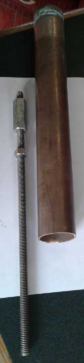 (29th) I was
concerned about the amount of friction this sort of system
might have, especially one with large threads. I got out a stainless
steel 3/8 inch nut and bolt, and they seemed to turn quite freely
against each other, even with axial pressure between them and no
lubrication. Even a long zinc plated coupling nut turned pretty freely.
The chief concern for friction then was the piston rings against the
cylinder walls. (Again I rather like the bicycle pump. Instead of
piston rings, sealing material - leather? - was attached to the face of
the piston, set up to expand and seal as the piston is pushed in, and
then pull away from the cylinder wall as it goes back. Thus it also
acts as the air intake mechanism. Perhaps I'll try something like that.)
(29th) I was
concerned about the amount of friction this sort of system
might have, especially one with large threads. I got out a stainless
steel 3/8 inch nut and bolt, and they seemed to turn quite freely
against each other, even with axial pressure between them and no
lubrication. Even a long zinc plated coupling nut turned pretty freely.
The chief concern for friction then was the piston rings against the
cylinder walls. (Again I rather like the bicycle pump. Instead of
piston rings, sealing material - leather? - was attached to the face of
the piston, set up to expand and seal as the piston is pushed in, and
then pull away from the cylinder wall as it goes back. Thus it also
acts as the air intake mechanism. Perhaps I'll try something like that.)
It looked like the chief reason to pick a diameter, at
least up to about 1/2", was how many turns per inch one wanted. That
sets the speed the piston moves in and out with "n" motor RPM and hence
the amount of air pumped. A higher RPM motor would use a smaller
threaded shaft. Without picking a motor yet, I thought a 3/8" threaded
rod and coupling nut (or a piece of a coupling nut) looked about right.
Low friction; too thick to flex when pushing against pressure.
The seal, whatever it was, could be on the front face with a washer
backing it, going out almost to the cylinder walls, and a rod or two
could be silver soldered to the back to stick out the motor end. These
would slide through something to prevent the nut from turning with the
rod (without needing an un-round cylinder and piston shape), and
provide a means for an optical interrupter to "see" when the piston
reached the end of the cylinder.
I also found in my stash some cupro-nickel (monel?) pipes, 1
inch and 1.5 inch. They both looked very smooth inside to use as
cylinders. (I would not, I expect, be using the full lengths of these.
Then again, why not? Fewer back and forth transitions is less stress,
less noise.)
With the whole mechanism being on-axis, the side-to-side
vibration of the crank rod would be eliminated. However, that would be
replaced by the continually reversing radial force. Would it be
quieter? I hope so! If it was controlled by a computer the transitions
could be made pretty smooth.
Well! I had certainly hoped not to get into this air heat
pumping idea so far as to be thinking about air compressor design! But
it seems key to "ultra-high" COPs. Am I
actually going to build one? Am I not spread thin enough already?
Another one to put in abeyance, I think, and just see what can be eked
out of existing compressors.
Fridge Compressor Disassembly
(21st) But first I wanted to take a apart a fridge compressor - the
first one, that didn't pump air very fast. I sawed the thick metal
shell apart by the seam with an angle grinder and zip disk, plus a
hacksaw.
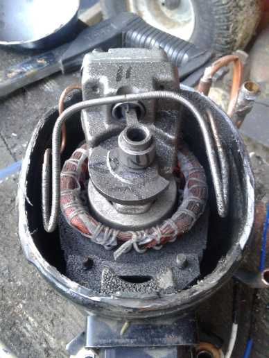 It
was
quickly
apparent
where
the
air bottleneck was: The
output from the compressor went through an extra long, itty bitty
copper tube/pipe to the far side, where it came through to the larger
pipe seen on the outside. All my efforts to get free air flow outside
were wasted with this severe restriction on the inside before it got
there. (In the fridge, the long tube would serve to isolate the
vibration of the compressor from the outside shell - which is itself on
rubber feet. Noisy as refrigerators are, the makers obviously go to a
lot of trouble to make them as quiet as possible. And with the long
length also the copper of the tube itself would be little stressed by
the compressor vibrations.)
It
was
quickly
apparent
where
the
air bottleneck was: The
output from the compressor went through an extra long, itty bitty
copper tube/pipe to the far side, where it came through to the larger
pipe seen on the outside. All my efforts to get free air flow outside
were wasted with this severe restriction on the inside before it got
there. (In the fridge, the long tube would serve to isolate the
vibration of the compressor from the outside shell - which is itself on
rubber feet. Noisy as refrigerators are, the makers obviously go to a
lot of trouble to make them as quiet as possible. And with the long
length also the copper of the tube itself would be little stressed by
the compressor vibrations.)
Obviously the amount of heat pumped is determined
by volume of air moving times the pressure of that air over outside air
pressure. Obviously this pump couldn't push much volume through that
tiny pipe without losing a lot of pressure, so the pressure had to be
high with low air flow volume. That probably reduced the efficiency of
the compressor and made it run warmer or hotter.
High COP is dependent on a low temperature lift. Aside
from that was there also a heat bottleneck from the compressor
to the
outside air?
First, the compressor cylinder appeared to be made of cast
steel instead of copper. Steel is doubtless good for durability, but
it's not a good heat conductor. And cast metal is full of tiny voids
(created as the molten metal cools and solidifies) - little heat
insulators. Thus the inside of the cylinder would surely run much
warmer than the outside (making a higher temperature lift), so even
putting heatsink fins on the outside of the compressor wouldn't really
solve the problem. I could see using a thin steel (or cupro-nickel?)
sleeve inside a copper tube (or even just some nickel plating on the
inside?), with heatsink fins on the outside.)
Then there was the fact that the whole compressor was
inside the outer heavy steel casing. No doubt the oil was slushing
around, hitting the outside of the compressor and transferring its heat
to the outer casing, but how effectively? I would have a hard time
judging that, but it's probably a significant resistance to heat
transfer.
Then once the warmed oil sloshed against the outer casing,
how effectively would it be dissipated to the outside air? My fan blew
air around it the whole compressor, but there were no heat dissipation
fins, and once again the case was steel rather than a good heat
dissipator like copper.
So it would seem there is actually a series of poor heat
transfer steps, all together constituting a considerable or perhaps
even severe bottleneck. This plus the restricted air flow may be
sufficient in themselves to explain COPs of 3-5 instead of 10-15.
They say air heat pumping is less efficient than with
refrigerant. Maybe it's because no one has tried to make an air
compressor to be efficient for air heat pumping?
and Reassembly
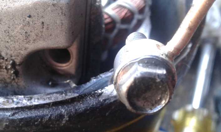 It seemed to me that the worst feature was that 1/16 inch
inner diameter tube, about 16 inches long, that the compressed air had
to somehow make its way through before it got to a reasonable size pipe
to flow in.
It seemed to me that the worst feature was that 1/16 inch
inner diameter tube, about 16 inches long, that the compressed air had
to somehow make its way through before it got to a reasonable size pipe
to flow in.
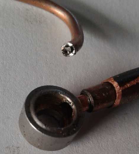 But I couldn't see any way to attach a bigger pipe except
to drill out the tiny hole on the side of the "washer" fitting larger,
and it could only be a bit larger because then the hole would hit the
end of the fitting. I got it up to 1/8" and found a tiny bit of pipe to
fit into it. It was just 1/4" long and the inside diameter was just
3/32". Still, that was 9/4 of the cross section and 1/64th as long. I
found another pipe to 'telescope' that out to a somewhat larger size in
which to bring the air out of the case.
But I couldn't see any way to attach a bigger pipe except
to drill out the tiny hole on the side of the "washer" fitting larger,
and it could only be a bit larger because then the hole would hit the
end of the fitting. I got it up to 1/8" and found a tiny bit of pipe to
fit into it. It was just 1/4" long and the inside diameter was just
3/32". Still, that was 9/4 of the cross section and 1/64th as long. I
found another pipe to 'telescope' that out to a somewhat larger size in
which to bring the air out of the case.
Now it was coming out of the case direct with the inner
compressor's vibration transferring to the radiator pipes. I hoped it
wouldn't be too noisy. But with the refrigerator compressors so far,
the air fan had been the bulk of the noise. Perhaps I could put a
resistor in the fan power supply - or just run it off 24 volts instead
of 36? - so it would run slower? But the first test would be with the
fan the same to help show the improvement, if any, in the compressor's
performance.
But having done this much, I was nervous about trying to
put the compressor back together without leaks. If it leaked it could
only be run for short tests and a demos. Then the larger fridge
compressor wouldn't start and I decided to try this one again after all.
Later I removed even the bit of smallest pipe and expanded
the hole to take what is the middle pipe in the photo. It worked much
better, delivering more air and was down as low as 55 watts pumping 20
PSI instead of over 70 pumping nothing.
But, the case seal being breached, even wrapped with PVC
tape I was leery of leaving it running unattended in case it should run
out of oil, and being such low wattage (65 W at 40 PSI) it would only
make 260 to 325 watts of heat at COP 4 or 5. And it was much noisier
with the inner compressor linked
through the case straight to the radiator pipes.
Makita Compressor
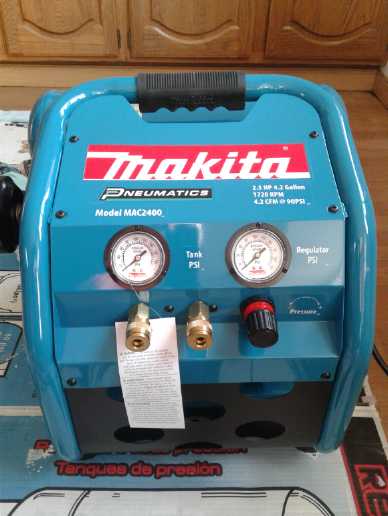 (22nd) Odd as
it may seem, I hadn't even opened the box of the big
Makita compressor that I had ordered and received almost a month ago. I
had wanted to try the refrigerator compressors as being smaller scale
experiments and tolerably quiet. I figured the Makita would want about
25 feet of
radiator pipe. That was going to take some making. But with the gift of
the aluminum finned pipes, I now had at least had 11 or 12 feet.
(22nd) Odd as
it may seem, I hadn't even opened the box of the big
Makita compressor that I had ordered and received almost a month ago. I
had wanted to try the refrigerator compressors as being smaller scale
experiments and tolerably quiet. I figured the Makita would want about
25 feet of
radiator pipe. That was going to take some making. But with the gift of
the aluminum finned pipes, I now had at least had 11 or 12 feet.
And I had been learning. The compressor has to go
inside the ductwork in a box so that its heat, and the motor's heat,
all contribute to the radiator air's heat.
I was
pleasantly surprised to see that the
cylinder with
some heatsink fins fed a fat 3/8" copper pipe that had aluminum fins on
it, and fed into the tank in a 16 inch length. Here was a setup that
would let lots
of air pass through freely! The motor of course had a fan, and the
whole had a plastic shroud so that that fan blew cool air over the
whole works.
Furthermore the compressor was oil filled. It was made to
run continuously, not just occasionally. And there was an air filter,
with an inlet fitting. That meant the air could be connected to the
incoming air side of the outdoor heat exchanger. Then the air both to
and from the compressor would connect outside the house, and would be
separate from the radiator fan air.
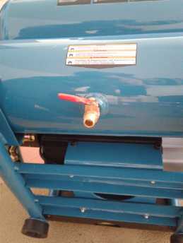 The compressor
and the air pipe to the tank run pretty
warm, not to say hot, even with the drain valve open (ie, no pressure
in the tank). Or perhaps because it was open? With the the valve open,
the unit drew about 550 watts. Once it was closed (after its 20 minute
break-in period), that went up to over 1100 watts with the pressure
nearing 130 PSI. To me that would seem to indicate 550 "wasted" watts
(probably somewhat less, since it was nevertheless moving air) and 550+
of watts actually compressing air... over 50% efficiency. (That beat
the large fridge pump: 100 W with the air output open and around 150 W
max when compressing heavily -- 33% efficiency.)
The compressor
and the air pipe to the tank run pretty
warm, not to say hot, even with the drain valve open (ie, no pressure
in the tank). Or perhaps because it was open? With the the valve open,
the unit drew about 550 watts. Once it was closed (after its 20 minute
break-in period), that went up to over 1100 watts with the pressure
nearing 130 PSI. To me that would seem to indicate 550 "wasted" watts
(probably somewhat less, since it was nevertheless moving air) and 550+
of watts actually compressing air... over 50% efficiency. (That beat
the large fridge pump: 100 W with the air output open and around 150 W
max when compressing heavily -- 33% efficiency.)
I decided I had been beating about the bush and that I
should set it up. With just 12 feet of radiator pipe it would run
warmer than it should, but with say 700 watts even a COP of 4 would be
equivalent to 2800 watts of baseboard heaters.
Now... yet another, and much larger, box to hold the
compressor. I went into town to buy some plywood, and I also borrowed
the rest of the radiator pipes that Mike had obtained. That make about
21 feet of radiator pipe. For the time being, that would save me from
having to make a jig and produce more 'stegosaur' copper finned
radiator pipes before I can try things out decently.
With this compressor moving a much higher volume of air, I
decided that the outdoor heat exchanger had to be done. All this was
adding up to a bigger job than just swapping compressors. Then I opted
to learn more first by experimenting more with the fridge compressors
and less radiator pipe.
Outdoor Heat Exchanger Install
Without an outdoor heat exchanger both fridge compressors,
even after improving the smaller one, performed poorly compared to the
first tests with one. I started to think the outdoor heat exchanger is
a much more important component than I had realized, not to say a vital
one. After all, it does the "heavy lifting" of bringing outdoor air up
toward room temperature as it enters the house. Otherwise the
compressor draws in cold air through window gaps and cracks.
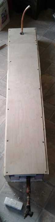 (27th) For the
outdoor heat exchanger I swapped my older pipe with the
homemade aluminum fins for one of the commercially made ones with far
more but a little smaller fins. It seemed to be about the right length
for my insulated box "duct", and its smaller fins would let air go by
more easily. To mount it against a house wall, I capped off the top
end, and soldered in a pipe with a gentle 90° bend (two 45°
elbows) and then a reducer from its 3/4" pipe to 1/2", to go through
the rear face and the house wall. Inside the house another gentle bend
(bent soft copper pipe) turned it parallel to and close to the wall to
attach the radiator piping and dryer air ducts.
(27th) For the
outdoor heat exchanger I swapped my older pipe with the
homemade aluminum fins for one of the commercially made ones with far
more but a little smaller fins. It seemed to be about the right length
for my insulated box "duct", and its smaller fins would let air go by
more easily. To mount it against a house wall, I capped off the top
end, and soldered in a pipe with a gentle 90° bend (two 45°
elbows) and then a reducer from its 3/4" pipe to 1/2", to go through
the rear face and the house wall. Inside the house another gentle bend
(bent soft copper pipe) turned it parallel to and close to the wall to
attach the radiator piping and dryer air ducts.
Owing to
having to make a hole in the wall of the house, I
wanted this to be "the" real install, not just a jury rigged test
setup. At first I thought to make a square hole in the house wall,
about 3x3 inches, the same as the duct. Then I realized that as there
would be no fins on the pipe going through the wall, it could be much
smaller. In fact, it didn't need to be a whole lot bigger than the 1/2
inch pipe of compressed air going out. So I drilled a circular hole
with a hole saw and put a piece of the PVC 1-1/4 inch (actually about
1.5" I.D.) "irrigation
system" pipe in it as a duct through the wall. With a similar hole in
the exchanger inner face, the PVC pipe brought the air directly from
the exchanger box to the inside of the house.
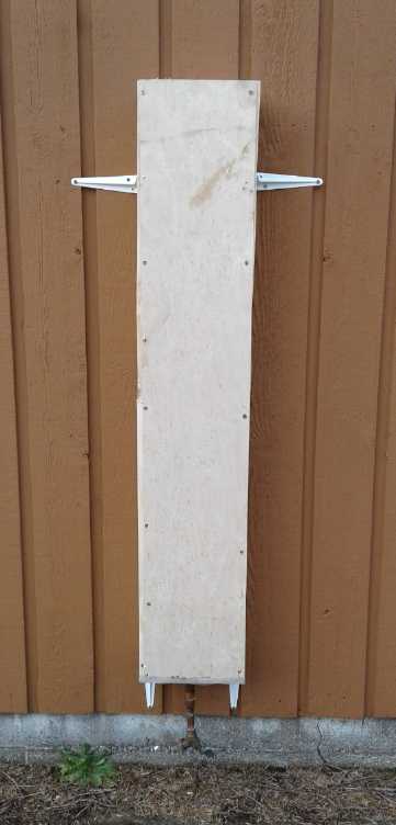 I pointed the
whole exchanger vertically down the wall,
with that hole and pipe into the house at the top end, and used four
"shelf brackets" to mount it against the wall. (Weatherproofing later,
but I did staple a window screen over the bottom to keep flies and bugs
out.) Warm air rises, so the warming air should naturally circulate
better as it goes up the duct, passing by the pipe fins and picking up
the heat from the outgoing compressed air, and then into the house
through the PVC pipe.
I pointed the
whole exchanger vertically down the wall,
with that hole and pipe into the house at the top end, and used four
"shelf brackets" to mount it against the wall. (Weatherproofing later,
but I did staple a window screen over the bottom to keep flies and bugs
out.) Warm air rises, so the warming air should naturally circulate
better as it goes up the duct, passing by the pipe fins and picking up
the heat from the outgoing compressed air, and then into the house
through the PVC pipe.
Before putting on the screen I stuck in a couple of pieces
of foam insulation at the bottom to narrow the outer air passage to
reduce wind blowing unwanted air in. I could still feel a draft coming
through the plastic pipe.
The compressed air pipe ends at a restriction valve far
enough below the bottom of the box that the cold outgoing air shouldn't
be drawn back in. (And a piece of garden hose can be attached to end it
even farther away if desired.) The vertical orientation opening at the
bottom will expel any water in the outdoor exchanger part of the piping.
On the inside, the PVC pipe could just end at by the wall
as at present, or more piping and a hose could route the incoming
warmed air straight to the compressor. I rather like the idea of
bringing fresh but not cold air into the room - without opening a
window. The compressor *should* still draw it through the exchanger. If
the air is routed straight to the compressor then just exactly what the
compressor needs is warmed and enters, and then it exits as compressed
air through the pipes, then is discharged/decompressed outside at
perhaps below outside temperature.
If the outdoor exchanger's intake is connected directly to
the compressor, its location is almost immaterial. But if it is to draw
(warmed) fresh air through the house on its way to the compressor, it
or its location could probably be improved. With it being on the middle
of a wall, if the wind puts it on the lee (low pressure) side, the
house would tend to draw more air through cracks on the windward side
and less through the exchanger. And of course when it's on the windward
(high pressure) side, instead it excess air would blow into it, to go
out the now leeward cracks. (At least its opening points down, not
straight into the wind.) Having the entrance to the exchanger away from
the house wall in a neutral wind pressure position might be optimum. Or
at a corner of the house might be better than the middle of a wall.
Well, wind always makes a house harder to heat. The tighter it is, the
less air the wind will push in and out.
This mounting should suffice. At least, having mounted it
I don't plan to change it. If it seems worth it, a possible improvement
besides moving the whole exchanger might be to have a duct it draws air
from, placed out in a more wind
pressure neutral location.
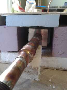 (March 4th) On
measuring temperatures in tests, I found other more important factors
than placement.
(March 4th) On
measuring temperatures in tests, I found other more important factors
than placement.
I had already reduced the large air gaps around the fins
(per image) by inserting some thin slices of styrene foam, because too
much air was coming in without being much warmed. (And maybe doing a
little more yet might further improve it!)
Next, the pipes themselves were transmitting coldness from
the outdoors and from colder sections below directly through the copper
to warmer areas. The pipe just indoors from the exchanger hole was way
below room temperature. The 9 inches or so of pipe sticking out below
the unit to expel the compressed air, transmitted the outdoor
temperature into the exchanger. The piping in the exchanger needed as
many thermal breaks as practical to isolate the differing temperatures
from each other. I unsoldered and put in three joins of PVC pipe to
make gaps in the copper: bottom, halfway, and just inside the house.
Even then, the incoming air was only being raised a little
over half way from outside to room temperature - maybe 60%. With all
due respect for the law of diminishing returns since the incoming air
will never quite get up to the temperature of the outgoing, I hope to
do better than that. It's probably a notable factor in the low COPs.
How much would more heat breaks help? Or perhaps the thing to do is to
double the length of the exchanger to 8 feet?
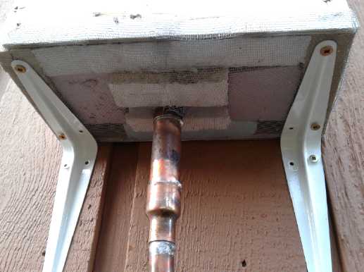 A couple of pieces of foam to reduce the
outdoor opening,
A couple of pieces of foam to reduce the
outdoor opening,
and a screen to keep bugs out. (I could just see a bumblebee
hive or thousands of hibernating flies taking up residence.)
Outdoor heat exchanger "in context" on the wall.
(If I have to make it longer, it'll have to be oriented diagonally.)
Thermal Breaks & A Better Way to join PVC Pipes to Copper Pipes
(no pipe fittings)
Perhaps of interest, I made the thermal break PVC pipe
pieces soft and
flexible like rubber hose by putting them in the kitchen oven at
250°F. That lets them fit over the copper pipes or soldered copper
pipe fittings. Then they harden again as they cool. (Wear gloves!)
They're soft for just enough seconds to put them on both pipes. Any
delay and they have to go back in the oven. Then I put pipe clamps
around them over each copper pipe. One I had to take off with vise
grips and then put it back on, and then it leaked. I could hear the air
hissing out. I took a hot air gun to it and managed to get the clamp to
seal. (The joins held 120 PSI.)
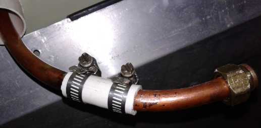 Inner thermal break.
Pipe on left going into heat exchanger is definitely colder.
(Aluminum sheet was to protect wall unsoldering the copper join.)
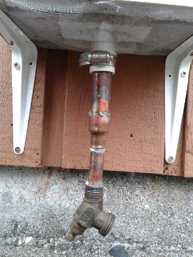 Outer thermal break at bottom of outdoor heat
exchanger box.
Outer thermal break at bottom of outdoor heat
exchanger box.
This one went over a 3/4 inch pipe and a slightly larger 3/4 inch pipe
fitting -
the advantage of soft and flexible!
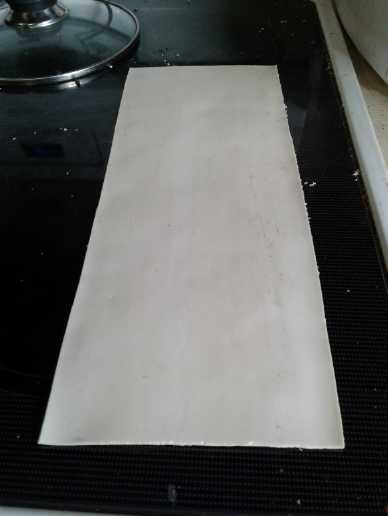 While I was at it, I had slit this larger PVC
pipe, and I softened it in the oven and turned it into a flat PVC
sheet.
(~5 x 12 inches)
While I was at it, I had slit this larger PVC
pipe, and I softened it in the oven and turned it into a flat PVC
sheet.
(~5 x 12 inches)
Tests
 I took a fair lot of readings in doing all
these tests
I took a fair lot of readings in doing all
these tests
(28th) I hooked up some radiator pipe and the "improved" water cooler
compressor. I had a hard time with leaks. The little compressor's
connections weren't very robust to start with, and now as modified they
were pretty fragile and came apart a couple of times. Each time I had
to untape the cut-open housing, fix it, and and tape it all up again so
the oil wouldn't spew out.
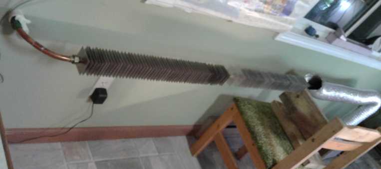
I was rather disappointed in the outdoor heat exchanger.
The compressed air pipe going out was only 13° where it entered the
exchanger (the room was 17°, so the incoming air was cooling the
pipe!), and what felt like a cold draft was blowing through it from
outdoors at 8°. Outside it was 5°. 13-5=8; 3/8=37.5% of the
lift available from the pipe. It was working and doing a fair job of
cooling the radiator pipe, even to a foot or so into the room, but it
wasn't warming up the incoming air anything like as much as I wanted -
only 37% of the way to the pipe temperature, and also the pipe was
being cooled by 4°. 17-5=12; 3/12=25% of the desired lift. That's
nowhere near the "law of diminishing returns" where more length of
exchanger would be helpful. Still, the principle is there. Even 3
degrees passive 'lift' is that much less 'lift' needed from the
compressor.
But it has to work better to get really high COPs. My
thoughts are that the smaller fins on its pipe leave too much gap
around the outsides and the outdoor air flows through too freely and
perhaps with poor heat exchange. Perhaps I'll try putting the other
pipe with the larger fins back in. Other than that, I'm now thinking
that routing the exchanged air into a hose that goes straight to the
compressor intake would slow the incoming air down and let it heat up
more on the way in, while also not letting any extra cool to cold air
into the room. Less air will get warmer if the exchanger isn't large
enough to warm a greater volume at a fairly high indoor-outdoor
temperature differential. Otherwise, an 8 foot exchanger length would
have much more warming capacity than 4... and of course 12 feet more
than 8, et cetera. -- provided of course that there's enough heat in
the outgoing air pipe, and of course until the incoming air is near
room temperature and won't pick up more heat no matter how much longer
it is.
With the room typically at 17.3 degrees, the fan took in
floor level air at 16.6 to 17.0 degrees and the warm air came out the
duct (which only had the one 'stegosaur' finned pipe) at 18.5 to 18.8
degrees. So the heat pump was heating air by almost 2° and that air
was being blown straight into the room. Another 4 feet of my aluminum
finned radiator pipe in open air (no duct) doubtless contributed a bit
more. (Of course the compressor itself, hidden inside its steel shell,
was running much warmer than any temperature to be felt outside, in
spite of the expanded outlet air pipe.)
The cord for the fan, which was more than long enough,
started mostly in the livingroom, and it seemed to slip farther and
farther through the tight fitting livingroom door every time in and
out. I didn't try very hard to push it back, and finally in the kitchen
area it was taut at ankle height and I tripped on it, which shifted the
box and made a pressure leak. I couldn't seem to close the leak while
it was running. Pressure went from 45 PSI to 35, and then I turned the
air pressure down to 30 at the outside valve so it would be letting out
more air there than at the leak. But it got worse and I turned it off
when it was down to 20. Thus ended the tests for February.
But until near the end of the test the room temperature
had been staying a pretty constant temperature despite only ~65 watts
of power and 5 degrees outdoors. Then I turned it off and turned on the
420 watt radiant heater. This seemed to keep the room at a similar
temperature, maybe a little better. Not bad to do similar with 65
watts! If it was even 325 watt equivalent, that's a COP of 5. Present
day heat pumps don't get that at 5° outdoor temperature.
The noise would be unbearable for regular use. With the
compressor's long, thin internal pipe removed and the output connected
straight to the radiator piping, everything vibrated. The larger fridge
compressor is fairly quiet and I won't modify it. For manufacturing,
something like my rotary screw compressor idea might be a lot quieter.
And a large diameter fan for the air is also quieter. Or
maybe a "squirrel cage" fan like in typical house furnaces?
I'm getting rather tired of soldering copper pipes and
fittings. (29th) Instead of changing the pipe in the outdoor exchanger
again, I have the idea to add more foam insulation on the inside to
narrow the duct. March 1st: did it.
Then I realized that the copper pipe, as well as
delivering the air to and from the fins for heat exchange, is
conducting cold from outside along its length to inside. Otherwise,
there was no reason the pipe should be colder than room temperature
inside the house near but not at the exchanger. I think I should break
it into three pieces with rubber pressure hose beatween them as thermal
breaks:
* the outside end below the exchanger where the compressed air is
discharged.
* lower and upper lengths inside the body of the exchanger.
* another thermal break where the pipe enters the house.
I can change the one long length of finned pipe inside the exchanger
for two short ones. Rats, more soldering to do!
---
I decided the next try would be with the larger fridge
compressor. If one could only get around 5 to 1 COP with an existing
compressor and my apparently inadequate outdoor heat exchanger, I
should use one that drew more than 65 watts to get some useful heat
from it. It would draw about double that, making 500 to 650 watts
instead of 260 to 325, which ought to heat up the kitchen area nicely
except on the coldest (or windiest) days.
Compressors make water in the pipes from air humidity. I
had noticed
"burbling" sounds the time I had used it previously, and when I plugged
it in (after having to fiddle with the connections to get it to start -
ug!) it spewed out a couple of tablespoons of
orange colored water. So I decided to elevate the box and have the pipe
come out horizontally instead of going upward. If the pipe started at
the highest point and all sloped down, all liquid should travel along
it and come out at the outdoor spigot.
The large fridge pump setup. Right to left:
*The box with the fridge pump and fan.
* 'Stegosaur' copper finned pipe in flexible dryer duct. (with air
pressure meter)
* Some aluminum finned radiator pipe mostly not in duct.
* Out through wall into outdoor heat exchanger. (2/3 plugged with foam
owing to high wind blowing in way too much air)
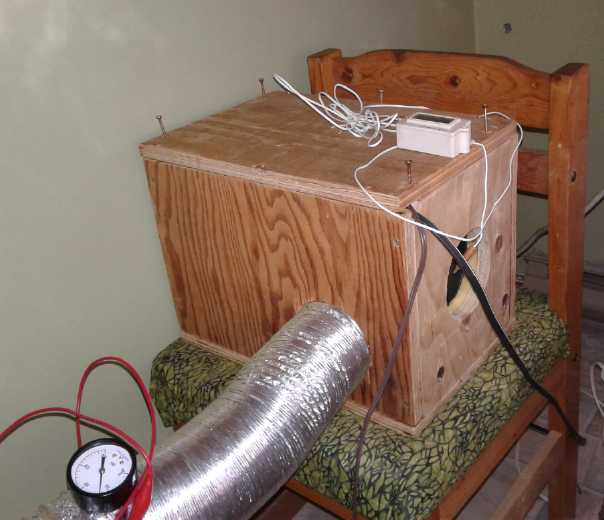 The compressor & fan in the box end.
To intrude slightly into
March, on March 3rd I put
together this configuration with the larger fridge pump. The warm air
was coming out 4.5 to 5.5 degrees higher than the room temperature
instead of 2+ to 3+.
The room temperature (once again) didn't rise with the
door to the livingroom (and the woodstove heat) and all other doors and
windows to the kitchen area closed, and in fact it sank very gradually.
Was it performing no better? Then I noticed frost and discovered it was
-1°C outside. The thermometer that read '+5' had been dropped and
was reading wrong. So actually it was doing pretty well.
(I have been struggling all along with a digital
thermometer that reads to .1°C but can take upward of 5 minutes to
get to and stabilize at a substantially different temperature. I
ordered 3 more digital thermometers on line in late January from
China... will they arrive?)
I adjusted the air pressure up and down, which changed the
warm air temperature slightly and the compressor watts considerably. I
got the highest temperatures with around 60 PSI. As the watts changed
substantially with pressure, it looks like lower pressure is
higher efficiency, but up to 60 or 70 PSI, higher pressure makes
slightly higher radiator temperatures.
I started leaving this running to help warm the kitchen
area. But only when I wasn't there - the fan was too noisy for when I
was.
(Next job: cut down fan speed. After that: put in the powerful Makita
compressor with all the radiator piping I can get or make. It's noisy,
but should heat up the place so fast it can be turned off much of the
time.)
The Grand Potential
Assuming high COPs can be attained, what might open loop
air heat pumping
replace? Here is a picture of the house circuit breaker panel.
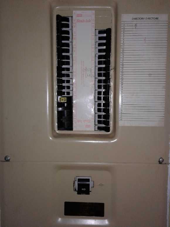
There are 11 double (230 volt) breakers:
* Workshop Sub Panel (The well water pump is the only major and
frequent load)
* Clothes Dryer
* Hot Water Tank
* Kitchen Stove
* SEVEN double breakers - over half - are for electric
baseboard
heaters, in a perhaps typical electric baseboard house:
- one - dual 30 amps (~5400 W)
- two - dual 20 amps (2 * ~3600 W
- four - dual 15 amps (4 * ~2700 W)
Without bothering to check out the rating of each heater,
at 75% of breaker capacity that's 85 amps, 230 volts or about 23,000
watts of electric baseboard heaters. Now just imagine instead a heat
pump with a COP of 15. That would need about 1500 watts of electricity
-
one single 15 amp circuit breaker -
to do the full capacity of all those 23,000 watts of baseboard heaters.
And it would have to be awfully cold to cause it to run full time or
most of the time. So it could heat the house for anywhere from zero to
say 80 $/month, depending on weather. If all those breakers were
removed the breaker panel would be just over 1/2 full and it is
apparent that the 200 amp panel has become "overkill".
That kind of performance could for the first time keep me
from lighting the woodstove most of the time in cold weather, keeping
it mainly as a
backup for power failures. Might it even be practical to heat a
greenhouse modestly warm, and light it with LED lights, for extended
season or even
year-round gardening?
And of course homes all across the north the world over
could benefit the same way in heating season. In some ways, this seems
almost as good as harnessing free energy. Winter loads on northern
power
grids will be dramatically reduced when this catches on.
Another configuration would do cooling
this way as well, again with an outdoor heat exchanger doing most of
the
'lifting' ('dropping?'). It's not needed in the very moderate coastal
climate here, but would surely be just as valuable a product for warmer
zones.
Additional Heat Pumping/Air Compressing Info Gleaned From Web
Here are some general heat pump stats for closed loop refrigerant based
heat pumps, in a New Zealand report:
Energy efficiency of [Refrigerant
Based] heat pumps for space heating
(Source: http://www.level.org.nz/energy/space-heating/heat-pumps/ )
As heat pumps only move heat and do not actually generate it, they have
a very high ratio of heat output to energy input. This heating energy
efficiency is expressed as a coefficient of performance (COP), while
cooling energy efficiency is expressed as an energy efficiency ratio
(EER).
Typical domestic heat pumps have a COP of 2-4.5, which means the heat
pump produces about 2-4.5 times as much heat as the electricity it uses
(under optimum conditions). Some heat pumps have COP's as high as 5.7.
The efficiency of an air-to-air [via
refrigerant loop] heat pump
decreases as the temperature difference between source and supply
increases - as outside temperatures drop, the heat pump's energy
efficiency [actually, its COP]
reduces.
Heat pumps are currently the only form of heating, aside from solar,
where the COP is (usually) greater than 1, which makes them the most
efficient [they mean "effective" or
"economical"]
form of purchased space heating commonly available. [Solar heating COP can be greater than 1?
How? Am I a nit-picker?]
The cooling energy efficiency ratio (EER) is typically about 2.5-4.0,
which means the heat pump produces about 2.5-4 times as much cooling
power as the electricity it uses. Some heat pumps have EER's as high as
5.8.
Yep! There are the low COPs
that drop
with outdoor temperature, pumping the least heat when it's coldest and
most needed. ...with the advantage in warmer climates that they can
cool as well as heat. But they continue:
"In a BRANZ study of 160 households with
heat pumps, more people said their energy costs had increased since
acquiring a heat pump than those who said their energy costs had
fallen. Only 15% described running costs as excellent. Occupants keep
their homes warmer than previously."
(23rd) Then, here is a link to an
article
about recovering and using waste heat from air compressors. They don't
expect to get as much heat out as the electricity put in. They consider
high temperature waste heat to be a free asset for heating instead of a
liability and make no
mention of COP anywhere. It would seem their
thoughts, like those of everyone I've been able to find so far, are far
from considering the potential of air compressors as heat pumps.
https://www.airbestpractices.com/technology/air-compressors/heat-recovery-and-compressed-air-systems
"Compressors are better at producing heat than compressed
air" says Tom Taranto of Data Power Services.
And here is a more in depth look at heating and cooling by
compressing a gas (air) than I have given or even thought of. But
after all, real gasses aren't "ideal" gasses:
https://youtu.be/EEUtRiuWK2o
Luckily this more involved bit of theory and math doesn't
change
the air heat
pump idea. It was never dependent on a specific volume of gas
reaching a specific pressure or temperature for a specific compression.
Rather I
realized the heat - however much from however much pumping - will be
carried off into the cylinder walls and into the compressed air flow
into the radiator pipes. And I also assumed the actual pumping
efficiency would be under 50% because everybody said so - but assuming
at least 25% could be attained.
I note (again?) that on a 'quora' web discussion page
someone said heat pumping with air takes a pretty high volume of air at
a high pressure. But just how much volume at exactly what pressure
works best for any given real compressor and set of radiator pipes is
probably easier to determine by doing it and trying out different
pressures than by academic formulae when complex parameters are not all
known (there are a lot of variables), and where gross mistakes might go
undetected for too long into a design.
My
Solar
Power
System
Month of February Log of Solar
Power Generated [and grid power consumed]
(All
times are in PST: clock 48 minutes ahead of sun, not PDT which is an
hour and 48 minutes ahead. DC power output readings - mostly the
kitchen hot
water heater for some months, then just lights - are reset to zero
daily (for just lights, occasionally), while the others are
cumulative.)
Solar: House+DC, Trailer => total KWH [grid power meter
reading(s)@time] Sky conditions
January 31th 03.76, - , 937.32 => 0.17 [85Km,charging;
71512@17:00]
dull. dreary. dim. rain. 3°.
February 1th 04.02,-, 937.33=>0.27 [55Km,charging; 71555@17:00]
Mostly dull, snow 0°. Collectors covered with snow except the two
on the lawn, which are set at a steep angle.
2th 05.06, - , 937.55 => 1.26 [71590@16:30] Sunny. 10 panels
still covered in snow. 1 was clear by late afternoon.
3th 05.39, - , 937.78 => 0.56 [71620@17:00] overcast & rain,
3°. Solar panels were clear of snow (viewed at end of day).
4th 05.74, - , 938.00 => 0.57 [71653@17:30;75Km,CarChj.] same as 3rd.
5th 07.28, - , 938.98 => 2.52 [71689@17:30] a bit of sun in the
morning, then cloudy.
6th 09.67, - , 940.16 => 3.57 [71715@17:00] Sun for the afternoon!
5°. Wow!
7th 10.91, - , 941.00 => 2.08 [85Km,charging; 71760@19:00] mostly
cloudy. 3°
8th (2.6*), - , 942.48 =>4.08 [55Km,chj; 71797@20:30] Mix of sun and
clouds *Estimate: Power bump in eve lost reading.
9th 01.27, - , 943.15 => 1.94 [50Km,chj; 71830(est)] mostly cloudy.
8°! (forgot to read - all are estimates from AM-10th.)
10th 2.56, - , 943.85 => 1.99 [71854@18:00] mostly cloudy.
11th 5.30, - , 945.48 => 4.37 [60Km,charging; 71885@18:30] I thought
it was light clouds. Did the sun come out?
12th 6.16, - , 945.98 => 1.36 [71914@17:30] Uggy. Wind & rain in
eve.
13th 8.45, - , 947.69 => 4.00 [90Km,chj; 71951@18:00] Some sun, some
clouds, some drizzle, some jet trails.
14th 9.63, - , 948.39 => 1.88 [85Km,chj; 71994@17:30] Clear almost
all night, then cloudy all day.
15th 12.23,-, 950.35 => 4.56 [60Km,chj; 72035(est)] Some sun.
5°. Sleet in evening.
16th 14.57,-, 951.91 => 3.80 [72064@18:30] Some sun. 2°.
17th 16.64,-, 953.31 => 3.48 [55Km,chj; 72104@19:30] Much more cloud
than sun.
18th 19.46,-, 955.58 => 5.09 [72125@18:00] More sun than cloud? Cold
wind, frost AM, 3°.
19th 20.52,-, 956.14 => 1.82 [55Km,chj; 72163@18:00] overcast until
sunset. 4°.
20th 22.35,-, 957.21 => 2.90 [72195@17:00] pretty much overcast -
lighter spots. 6°.
21th 25.17,-, 958.73 => 4.34 [85Km,chj; 72228@18:00] Light overcast,
hazy sun later PM.
22th 27.64,-, 960.50 => 4.24 [55Km Chj; 72264@19:00] Frost AM. More
light overcast.
23th 30.69,-, 962.14 => 4.69 [72289@18:00] Some sunshine! Frost AM.
Hit about 5°.
24th 32.15,-, 962.97 => 2.30 [72325@18:00] Frost. Rain. Clouds. Wind.
25th 34.75,-, 964.53 => 4.16 [72350@18:00] Frost. Clouds. Rain. Sun
later PM.
26th (3.33*),-,966.53 =>5.33 [72369@18:00; 55Km car charging]
Clouds. Rain. Bit of Sun. *est - Power failed for an hour ~16:30, lost
reading. 13°.
27th 03.11,-, 968.71 => 5.29 [72406@23:00] Rain. Sun. Rain. Sun.
Rain & sun. 10°. Frost & stars after dark.
28th 06.34,-, 970.82 => 5.34 [85Km,charging; 72437@18:00] A fair bit
of sun but some clouds.
29th 09.00,-, 972.49 => 4.33 [55Km,chj; 72475@19:00] At one point,
the sun came out.
March
1st 10.36, 973.25 => 2.12 [40Km,charging; 72500@19:00] Heavy
overcast, rain: dull.
2nd 14.06, 975.32 => 5.77 [72528@18:30] Mostly SUNNY!
3rd - Power failure and huge windstorm brewing. I decided to
unplug the grid tie inverters and leave them off for now. I don't want
them damaged by power bumps. I turned them on mid-late PM on the 5th. I
also put a "watch" battery in the house power logger so it wouldn't
lose
readings in power failures (which did again start at 0). Probably about
1 KWH attributed to the 6th was actually collected on the 5th. Still,
the increase from 5.xx to 8.xx KWH is considerable.
6th 05.88, 979.21 => 9.77 KHW [35Km,Chj; 72665@18:30] Sunny (with
snow
flurries). (Includes ~3/4 KWH from 5th PM.)
7th 11.13, 983.09 => 9.13 [55Km,chj; 72695@18:30] Sunny.
Daily-
KWH- # of Days (February)
Made
0.xx - 3 (near start of month)
1.xx - 6
2.xx - 4
3.xx - 3
4.xx - 9
5.xx - 4 (more 4.x and 5.x as month went on.)
6.xx -
7.xx -
8.xx -
9.xx -
10.xx-
11.xx-
12.xx-
13.xx-
14.xx-
15.xx-
16.xx-
Monthly Tallies: Solar Generated KWH [Power used from grid KWH]
March 1-31: 116.19 + ------ + 105.93 = 222.12 KWH - solar [786 KWH -
used from
grid]
April - 1-30: 136.87 + ------ + 121.97 = 258.84 KWH [608 KWH]
May - 1-31: 156.23 + ------ + 147.47 = 303.70 KWH [543 KWH] (11th
solar panel connected on lawn on 26th)
June - 1-30: 146.63 + 15.65 + 115.26 = 277.54 KWH [374 KWH] (36V, 250W
Hot Water Heater installed on 7th)
July - 1-31: 134.06 + 19.06 + 120.86 = 273.98 KWH [342 KWH]
August 1-31:127.47 + 11.44+91.82+(8/10)*96.29 = 307.76 KWH [334 KWH]
(12th panel connected on lawn Aug. 1)
Sept.- 1-30: 110.72 + 15.30 + 84.91 = 210.93 KWH [408 KWH]
(solar includes 2/10 of 96.29)
Oct. - 1-31: 55.67 + 13.03 + 51.82 = 120.52 KWH, solar
[635 KWH - from grid]
Nov. - 1-30: 36.51 + 6.31 + 26.29 = 69.11
KWH, solar [653 KWH - from grid]
Dec. - 1-23: 18.98 + .84* + 11.70 =
31.52
KWH, solar + wind [711 KWH + 414 (while away) = 1125 from grid]
Jan. - 6-31: 17.52 + ------* + 10.61 = 28.13 KWH,
solar+
wind [1111 KWH from grid]
Feb. - 1-29: 56.83 + ------* + 35.17 = 92.00KWH,
solar + wind [963 KWH from grid]
* Solar hot water tank removed because the mineral-rich water stank.
(Why doesn't it stink in the main house tank?) Now the solar DC system
is only running a couple of lights - not worth reporting. So there's
just the 2 grid tie systems, house and "roof over travel trailer".
Analysis of a Whole Year's Figures
12
month total March 1 2019 to February 29th 2020: 2196.15 KWH made;
[7927 KWH
consumed
from grid]
In the usage figures it must be considered that I have an
electric car, which is always charged at home. Owing to my country
location I drive around 900 Km a month even tho I only drive every
second day or so, getting around 7 Km/KWH (10%(?) less in winter
weather). Assuming 85% charging efficiency, that's 151 KWH/month as a
rough estimate. (For comparison, the 500 watt heater in the trailer to
keep it from going mouldy uses 360 KWH/month! And it doesn't keep the
trailer warm enough to live in.)
The wind power generated and used was too little to bother
about. If I get a grid tie inverter for the windplant, or if I once
again make more use of the battery system, it will contribute some
small increase to the totals, but while we occasionally get very strong
winds here, there are way more calm days than windy ones, and winds
providing over 100 watts from this windplant are even more rare.
Apparently all the renewable energy made over the year was only 22% of
my total electricity usage. Well, I knew there wouldn't be much solar
energy in the winter around here with the short, cloudy days and the
sun just 15° above the horizon at noon - which is of course just
when a lot of extra juice is used for heating, even with the woodstove
supplying the bulk of the needs. (That may change! Open loop air heat
pumping dangles the promise of very cheap electric heat.) Using the
above estimates 1812 KWH were for the car. One might say the solar
electricity if nothing else at least paid for all my energy costs for
driving it, with 400 KWH to spare.
Most of the solar energy was harvested in the 7 best
months from March to September 2019: 1854.87 KWH. In that same period
3395 KWH was used from the grid so the ratio was 35% solar to 65% grid
power. The car would have been around 1057 KWH of that, so home use
would have been 2338 KWH, of which 800 came from solar.
It might almost be said that in the worst four months put
together (November, December, January, February), less electricity was
made than in any one of those seven best months (220.76 KWH).
So if I was serious about, on average, supplying all my
needs with solar, I would need about 55 solar panels. That many would
make up in summer for the deficit in winter. (Effective heat pumping
would reduce that. Arguably it could save 25% of the total power
consumed, which would bring it down to 41 solar panels.)
Things Noted - February
* As February went on, the days
lengthened, there was (a bit) more sun and it was higher in the sky,
and solar output increased substantially, from "very little" to around
5 KWH/day - which is still only about 1/3 as much as on sunny days in
the summer.
* The total for the year from March 2019 to February 2020 shows that
with just 10 to 12 panels, the solar output was only
22% of the energy used - not insignificant, but
not a major replacement, especially in the about five months with the
least
sunlight.
* There was only one sunny and nice day in January, and one in February
until the 23rd. Even well into March it forze every night, and there
was snow. Egads! (No wonder I haven't been milling the last of my
log into lumber!)
* The windplant spun for some hours on several days, but I didn't make
any use of it except to run a little heater in the garage - just to
keep it from revving up too high. The heat could be felt by the heater,
but was trivial for actual heating - tens of watts. (Now if that could
be multiplied by COP of 10!...)
Electricity Storage (Batteries)
Turquoise
Battery
Project:
Long
lasting, low cost, high energy batteries
Dip-Plated Zinc Electrodes
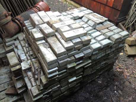 An impressive stack of zinc ingots cast
from discarded boat/ship protective anodes
A reader in Oregon, Peter Carlich, who has been collecting
zinc said he wanted to make batteries. He offered to cast zinc
electrodes. I said it just needed thin zinc with lots of surface area
per volume, which didn't lend itself to casting. I said I was going to
try electroplating thin copper sheets with zinc. He then offered to dip
plate copper sheets in melted zinc. That sounded promising and I said
"Sure!" He has proceeded with that and is sending me some samples in
the mail. He also took some pictures.
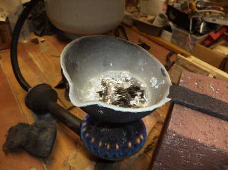 Zinc melting setup.
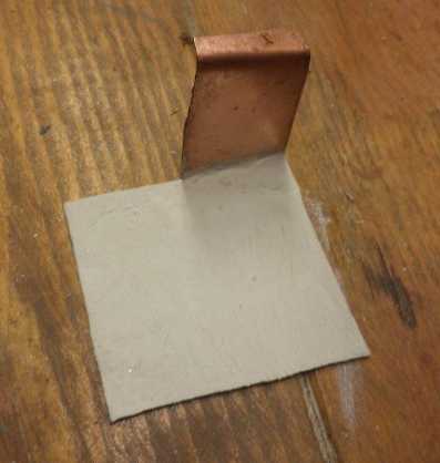
The backs of the sheets were protected from
plating with a clay mixture,
and the fronts were covered with flux so the zinc would adhere well.
Zinc plated copper sheet.
Powder Electrodes Conductivity
(3rd) I took the nickel manganate mix from the previous electrode,
dried it, and torched it. I compacted it to 5 tons and replaced the
other electrode with it. I still didn't get good conductivity from it.
Well, it was just graphite powder for conductivity.
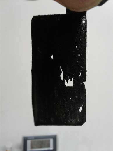 In reassembly I noted that the zinc sheet now had some
holes in it. Perhaps it was just too thin a piece, or perhaps in
pressing so
much of my weight on it I had squeezed out some of the gel and left it
vulnerable.
In reassembly I noted that the zinc sheet now had some
holes in it. Perhaps it was just too thin a piece, or perhaps in
pressing so
much of my weight on it I had squeezed out some of the gel and left it
vulnerable.
(4th) I then took the one with the
graphite felt (which was still in
three main pieces rather than crumbled into little bits), dried it and
torched it. I decided to use a new sheet of zinc for the other side -
and simply a sheet, no processing. I wouldn't worry about cycle life,
amp-hours capacity and dendrites for the moment.
Solid Porous Electrode Briquettes - Plaster
(8th) I had been racking my brain trying to figure out what I might add
to an electrode to keep it from swelling when liquid was added to the
assembled battery. On this morning suddenly the words "Plaster of
Paris" entered my head. I thought, maybe that's what the electrode
needs. It sets solid when it dries, but it's still porous.
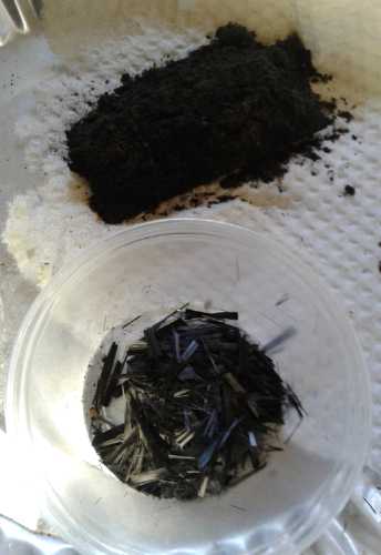 I
had also decided to try mixing some short strands of
carbon/graphite fiber into an electrode. I took my bag with just a few
loose scraps and cut all the fibers into lengths of 1/4 to 1/2 inch or
so. They didn't need to be very long to touch each other and to touch
the current collector to make random connections all through a 3mm
thick electrode. It took a few minutes, and it all added up to a
whopping .35 grams. I added that to the powder from the previous
electrode that had had only graphite powder conductivity additive. The
total was 6.05 grams.
I
had also decided to try mixing some short strands of
carbon/graphite fiber into an electrode. I took my bag with just a few
loose scraps and cut all the fibers into lengths of 1/4 to 1/2 inch or
so. They didn't need to be very long to touch each other and to touch
the current collector to make random connections all through a 3mm
thick electrode. It took a few minutes, and it all added up to a
whopping .35 grams. I added that to the powder from the previous
electrode that had had only graphite powder conductivity additive. The
total was 6.05 grams.
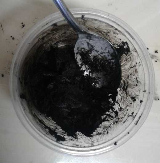 To this I
added 1.95 grams of powder from a bag labeled "casting
plaster", total 8.0 grams. (This I had purchased some years back with a
like quantity of high temperature silica powder potentially for
aluminum casting.) Then a couple of drops of the sulfonates-rich
dishsoap and a little water.
To this I
added 1.95 grams of powder from a bag labeled "casting
plaster", total 8.0 grams. (This I had purchased some years back with a
like quantity of high temperature silica powder potentially for
aluminum casting.) Then a couple of drops of the sulfonates-rich
dishsoap and a little water.
This mixed into a nice
paste, which I put
in the compactor. It seemed too wet. From experience I thought it would
ooze out through every tiny crack if I put it in the hydraulic press,
but I did anyway since that might mix things even better, at the micro
level, and then I would redo it. Instead only a little liquid oozed
out. The
powders stayed and made a ~2mm thick electrode.
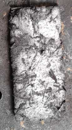 Then I set it
by the fan from the woodstove to
dry and set
the plaster. Four hours later it had developed a mottled appearance
with white areas - perhaps "not so well mixed in" plaster patches?
Then I set it
by the fan from the woodstove to
dry and set
the plaster. Four hours later it had developed a mottled appearance
with white areas - perhaps "not so well mixed in" plaster patches?
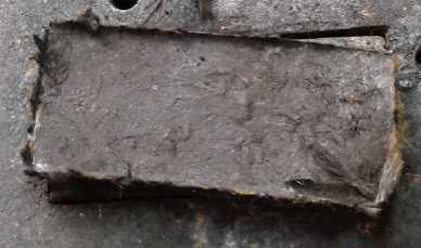 I
pulled it out of the die. I turned it over and found out why it hadn't
oozed out: the graphite fibers had oozed down and filled the gaps.
That I turned it over without it crumbling or breaking was in itself a
good sign. The bottom face was uniformly dark.
I
pulled it out of the die. I turned it over and found out why it hadn't
oozed out: the graphite fibers had oozed down and filled the gaps.
That I turned it over without it crumbling or breaking was in itself a
good sign. The bottom face was uniformly dark.
(9th) The dried electrode measured in the hundreds of ohms range with
the meter leeds across any two points on the surface on either side,
although it was quite variable across different points. This was
encouraging since they are often far higher once the electrode is dry.
(When it's wet, one is measuring ionic conduction in the water, not the
electron conduction in the substance. This always measures as a low,
but in an electrode meaningless, resistance.) I measured a piece of dry
Ni(OH)2 electrode (doubtless well discharged) from a commercial NiMH
"D" cell. It was upper tens to lower hundreds of thousands of ohms - a
couple of hundred times less conductive. All that graphite plus the
graphite fiber strands certainly must have worked, and the plaster
didn't seem to have hurt it. And nickel manganates has higher
conductivity than nickel [oxy]hydroxide to start with. The potential is
there for very high currents.
And in these manipulations it still hadn't crumbled or
cracked. Yay! The chief question now was: would it swell and lose
conductivity when wetted in the cell, or hold its form? On finding out
that plaster could take 72 hours to completely set, I decided I'd
better leave it for another day or two before trying.
Some theory/ideas
What was "Plaster of Paris", anyway? I was only sure it
must contain calcium. It turned out to be calcium sulfate hydrated with
just one H2O molecule per two CaSO4's. When wetted, it "sets" by
turning into the dihydrate form, CaSO4 . 2 H2O, which is solid. -
also known as gypsum or plaster. It takes some hours to set, and
apparently "up to 72 hours" to be completely set.
(This form of calcium is as opposed to calcium
oxide/CaO/lime/quicklime. When wetted this turns into Ca(OH)2/slaked
lime/calcium hydroxide, which in the open sets to limestone/calcium
carbonate/CaCO3 by reacting (if wet) to CO2 in the air. It
is the base active material for cement, mortar and concrete. One
reverses the reaction and turns CaCO3 back into CaO + CO2 by heating it
to 800°C - which I have done in the mini kiln to make CaO.)
It seems likely or at least possible that the layer of CaO
I've been putting in my positive electrodes could react with the
organic sulfates in the dishsoap to form gypsum and organic oxides.
(Eg, Ca(OH)2 + ? H2O + sodium lauryl sulfate => CaSO4 . 2 H2O +
sodium lauryl oxide.) But I don't see how that would disperse to
solidify the electrode. Maybe I'll try mixing a bit of CaO (lime
powder) into the electrode next time instead of quite a lot of CaSO4 .
1/2 H2O (plaster powder). Or maybe some of each. Well, let's see what
happens with this one first!
Of course the above substances are all electrical
insulators AFAIK. But they are porous and should allow ions from the
electrolyte to pass. At the ultimate, one might encase the compacted
electrode and current collector in a "box" of cement or plaster all
around the outside. Theoretically that should keep the electrode from
swelling, yet allow electrolyte through.
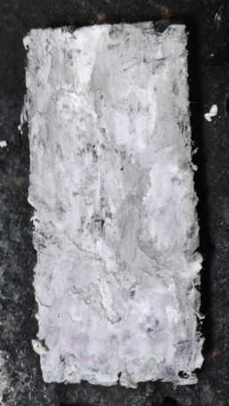 (10th) I
wonder how a layer of cement or gypsum would perform as a
separator between electrodes? In fact, I think that would be a good way
to do it. Paint the layer of CaO / Ca(OH)2 onto the face of the
electrode. Then instead of putting the cell together immediately, leave
it a couple of days to set, to react with the CO2 in the air. Maybe a
couple of coats. Then there's a thin, insulating and insoluble but
porous surface layer of calcium carbonate/CaCO3/limestone - on the
electrode. That should completely replace the need for a
separator sheet or grille. The jell layer on on the zinc would also
help insulated the common surface. And the limestone would be quite a
thin layer compared to a grille, making for fast response to sudden
current draws.
(10th) I
wonder how a layer of cement or gypsum would perform as a
separator between electrodes? In fact, I think that would be a good way
to do it. Paint the layer of CaO / Ca(OH)2 onto the face of the
electrode. Then instead of putting the cell together immediately, leave
it a couple of days to set, to react with the CO2 in the air. Maybe a
couple of coats. Then there's a thin, insulating and insoluble but
porous surface layer of calcium carbonate/CaCO3/limestone - on the
electrode. That should completely replace the need for a
separator sheet or grille. The jell layer on on the zinc would also
help insulated the common surface. And the limestone would be quite a
thin layer compared to a grille, making for fast response to sudden
current draws.
And maybe a bit of limestone mixed in would be better than
plaster for holding the electrode together, too? Limestone has the
appeal of being completely insoluble in water, whereas plaster is
slightly soluble and might gradually migrate.
A small aggravation is these things taking days to set. I
tried to put on a second coat 3 or 4 hours later, but it just lifted
and mixed with the first one. Well.... on to something else then!
50x50mm Electrode Compactor
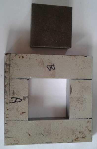 The high conductivity measurements seemed to portend near
readiness to make production size cells, something a little bigger and
heftier than the test cells. I rather liked the 100x100mm size idea.
(4"x4" - hopefully good for a few amps.) But that would need a lot of
pressure to compact, and even a 1/2 inch steel compactor might flex a
bit if not bend. I thought that instead one could make 50x50mm
electrode bricks and just put 4 of them together in a square on one
current collector to make 100x100. I could also do 50x50mm and 50x100mm
test or small size cells and (eg) 150x150mm (6"x6") or even larger
large
ones (up to what the 3D printer could do - 150 or maybe just barely
200x200 mm).
The high conductivity measurements seemed to portend near
readiness to make production size cells, something a little bigger and
heftier than the test cells. I rather liked the 100x100mm size idea.
(4"x4" - hopefully good for a few amps.) But that would need a lot of
pressure to compact, and even a 1/2 inch steel compactor might flex a
bit if not bend. I thought that instead one could make 50x50mm
electrode bricks and just put 4 of them together in a square on one
current collector to make 100x100. I could also do 50x50mm and 50x100mm
test or small size cells and (eg) 150x150mm (6"x6") or even larger
large
ones (up to what the 3D printer could do - 150 or maybe just barely
200x200 mm).
Thus the idea to make a 50x50mm compactor punch and die. I
had a big piece of 1/2" thick stainless steel. Someone happened to be
discarding it at the refuse trasfer station just when I was there
looking for something else. Yay! (And just after I had bought a piece
of ordinary 1/2" steel! Stainless will be better.)
There was lots of the stainless to make as many compactors
as I wanted. It occurred to me that one could stack four compactors in
the press and compact them all at once. They would all need the same
pressure - just 1/4 of what a single 100x100 compactor would need.
Another idea to save for later. One would be enough work to make.
I had thrown the "stainless steel" plate on the grass
outside the storage room months back. When I picked it up... the bottom
was rusty! But it was still shiny on top. What was it really? Two
layers? I decided to use the other steel after all. I spent some hours
cutting out the pieces for the die and the punch. I would file and
grind them to exact dimensions another time.
(22nd) That
time came over several rather grueling sessions of filing
and grinding,
several hours in total. On this day I had the die to the right size. I
think.
(25th) I finished it this day. I took considerable pains to get it
perfect. I must have done well because on the last edge filing, the
punch that didn't quite fit in
any direction, suddenly fit through,
equally in all four directions.
Tests
(11th) The new graphite foil tab had cracked and folded the same as the
previous one and became virtually disconnected. Obviously I needed a
new cell with a layout that would work. However, I stuck in another
piece of graphite foil, and while the connection to the electrode was
never satisfactory or consistent, it was there. (Wiggling it around or
otherwise adjusting always made the voltage under load go up or down.)
* Short circuit current was just .25 amps, but there was almost no fade
after 10 seconds.
I did a load test with 60 ohms, and without much charging beforehand.
It started out over 1.4 volts, but in under 10 minutes fell below 1.3
volts.
* The voltage stayed over 1.2 volts for almost an hour. That was a big
improvement over previous electrodes.
* I kept trying to get better connections, which made at least tens of
millivolts difference (up or down), including opening the cell a couple
of times. In doing this I noted that the electrode brick seemed to have
not swelled, and it hadn't broken. It remained a one-piece brick, which
could be shoved around. Yay! (I'm not sure why it was smaller than the
space, that it had room to move!)
* I took out the separator grille and tried just the two electrodes
together with the calcium oxide/carbonate layer for separation. It
didn't work. If it wasn't a short circuit, there was at least some
significant conduction between them.
* I replaced the separator grille with a piece of parchment paper. The
voltage went up by about 25mV. (We'll keep the parchment paper, then?)
* The conductivity still wasn't very good. A pound or
two of weight on top helped considerably. (No doubt it would with a
gold plated current collector, too.) OTOH gold plated copper proved
less than reliable in its first test. I clamped another stiffer
alligator clip over the one on the graphite and got a few more
millivolts.
* After an hour and a half (~60 mA-H), it hit 1.0 volts, and it didn't
go much longer. I could visibly watch the drop accelerate. It plunged
from .95 to under .90 volts in seconds - just like a real battery that
was right out of juice.
Voltage recovered in 15 minutes to 1.271. Then I put it on
charge (@ 1.943 V). This time the voltage didn't jump up to near a full
charge voltage, only to 1.6 volts. It started charging at 100mA and
gradually over minutes the voltage rose and the current dropped. In 5
minutes it hit 1.750 volts and was still drawing 65mA. This certainly
seemed like a huge improvement over any previous. It was taking a
charge the way an electrode - and a cell - should.
After 15 minutes I realized that I had the current meter
on 0-200 mA, and that that meter range itself imposed a consderable
resistance in the circuit. I moved it to the 0-10 A range, and I tried
briefly shorting the cell. Short circuit current went up to half an
amp, albeit with considerable fade over 10 seconds. Then voltage and
charging current went up and charging was going much faster, initially
back up to 80mA. (or should I say, on this scale, .08 amps?) The cell
hit 1.9 volts (@ .03 amps) in 11 more minutes.
(12th) After charging some again the next morning (I left it off for
the night), the voltage quickly dropped into the 1.7 volt range. Anyway
I ran a load test. It wasn't as good, running not much more than an
hour.
Then I charged it again. This time the charge voltage was
up to 1.93 and off charge it stayed over 1.8 volts for a bit. But short
circuit current was down under 1/2 an amp, so I wasn't optimistic. But
I ran another 60 ohm load test, and this time the voltages stayed
higher longer and it lasted exactly 2.5 hours before dropping below 1.0
volts - almost 50 mA-Hours. Now that's at least starting to sound
promising!
Would it get better yet, or was that it? Or would it start dropping? At
least it hadn't started dropping like MnO2 did by the third test.
A six minute test then stayed above 1.5 volts but I shut
it off. Then 1.5+ volts for 8 minutes and over 1.4 for 45 minutes. It
ran for an hour late that evening with the highest discharge voltages
yet. It looked like it would go at least 3 hours, and maybe longer.
(That would have made it a very late night.) So apparently it
improves with cycling - as I see it, turning the Ni(OH)2 and KMnO4 into
nickel manganates (NiMn2Ox, Ni2MnOx) - and probably some extra KOH and
O2 gas. Whatever is actually happening the chemistry, and the plaster
and cement making it a good brick, now look clearly like winners.
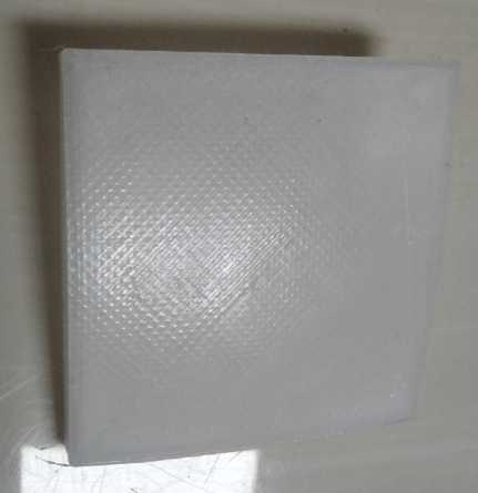 I
also 3D printed a 50x50mm case in nylon. I filled it
with water to check for leaks. Later there was a puddle under it. But
had I filled it too full, and the water crept over and went out a screw
press? I wiped off under it and filled it again, not quite so full.
I
also 3D printed a 50x50mm case in nylon. I filled it
with water to check for leaks. Later there was a puddle under it. But
had I filled it too full, and the water crept over and went out a screw
press? I wiped off under it and filled it again, not quite so full.
(13th) The nylon case had swelled up with the moisture and the flat
bottom was now dish
shaped. So much for nylon for cases! And PLA had disintegrated in an
alkaline environment. That took me back to ABS and needing a 'heated
oven' (or a noisy heat gun blowing at the work) for the lengthy
printing times - which are only longer with the Cura slicer than with
the old Skeinforge.
I also did another 60 ohm
load test. I had taken it off
charge some hours previously, and while I "topped it up" for 15
minutes, It looked like it was only going to be a mid-range for
performance, losing voltage more quickly than the last two great tests.
But I ran it down to 1.0 volts, and along the way the voltage drop
slowed to a crawl - about one millivolt drop per minute, then even less
- taking 3 hours and 33 minutes to drop under 1.000 volts, having
delivered around 63m mA/hours of current.
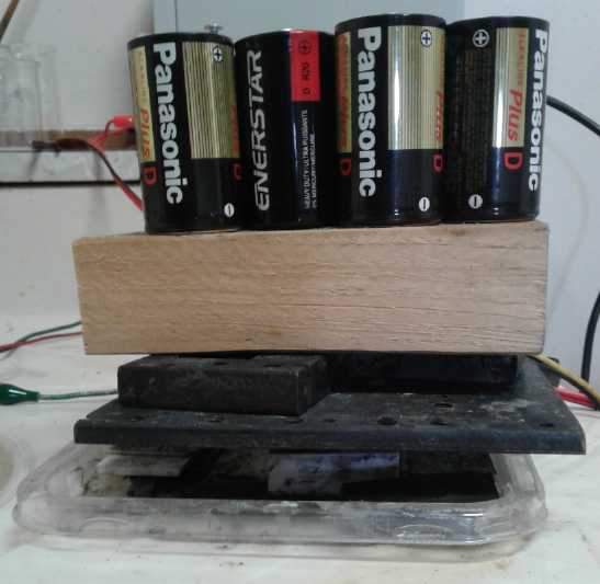 At 1.051v I
put a couple of pounds of weight on top of the
cell, and the voltage rose to 1.073. (It obviously gave some more time
because of that.) Once again, the better the internal connections, the
higher the voltages under load, and I'm sure the more milliamp-hours
that will be supplied. I don't think I've done enough yet, even with
the plaster and cement, to make them stay properly conductive. Perhaps
very solid bottoms and tops of the cell cases, glued together under
some pressure, would be better. After all, that's why so many batteries
come as cylinders that can keep it all tightly compacted. Perhaps
that's what it needs. In fact, one suspects what drove manufacturers to
cylindrical cells in the first place.
At 1.051v I
put a couple of pounds of weight on top of the
cell, and the voltage rose to 1.073. (It obviously gave some more time
because of that.) Once again, the better the internal connections, the
higher the voltages under load, and I'm sure the more milliamp-hours
that will be supplied. I don't think I've done enough yet, even with
the plaster and cement, to make them stay properly conductive. Perhaps
very solid bottoms and tops of the cell cases, glued together under
some pressure, would be better. After all, that's why so many batteries
come as cylinders that can keep it all tightly compacted. Perhaps
that's what it needs. In fact, one suspects what drove manufacturers to
cylindrical cells in the first place.
(14th) Cylindrical Cells?
Making flat electrodes and cells seems so nice and
logical, and so
simple - until confronted with the fact that they definitely seem to
work best if well pressed together. In particular, the positrode brick
needs to be well pressed against its current collector. The best thing
to hold pressure is a sphere. That's impractical. Next best is a
cylinder. But how would I make cylindrical cells
utilizing my techniques?
1. Simplicity would suggest doing it way of typical standard cylinder
cells: a layer of zinc plated sheet electrode around the
outside, a single separator sheet, and a fat nickel manganate plug with
a carbon rod in the middle. Some single-piece metal can would have to
be found. It shouldn't be hard to paint it on the inside with the
osmium dope layer - just pour some in, swish it around, and pour it
back. Then put in a round piece of cardboard to cover the bottom. The
electroplating would be similar: fill the cell to the desired level
with the plating solution, put a zinc anode in the center, and plate
for a desired number of amp-hours. For the agar jell, again fill up the
cell, but heat it so the jell doesn't set until after it's been poured
back out, to get a fairly thin coating. Next roll up and insert the
separator sheet.
There would have to be some jig to insert a compacted
cylinder of NiMnOx mix. Perhaps a thin walled plunger with a piston of
some sort to compact it and then press it out. (It seems Sanyo did it
as three short cylinders, even in an 'AA' cell.)
But this construction doesn't make for a very high current
cell.
2. The best cylindrical battery would probably be made with
rolled-up
electrodes like Ni-MH and Ni-Cd cells. This makes for far more
interface area between electrodes. The electrodes in the Ni-MH 'D'
cells were about 50mm x 500mm, for a total of 250 square centimeters of
surface. And both surfaces of the interior layers are in contact with
each other, adding a lot more and making it perhaps 425 sq.cm. That's
where they get the "50 amps" momentary current capacity, where the
Mn-Zn alkaline cells 'only' put out about 10 amps shorted. Both figures
probably represent 100-200 mA/sq.cm. of interface surface. (Mn-Zn in
salt only gives around 5 amps in spite of the whole circumference of
the cell inside the zinc being the interface area - 80 mA/sq.cm.)
It would be no problem rolling up a thin sheet of zinc
plate. For the plus side, perhaps I should be thinking of
compactors that make semi-circular sheets, in diameters - or even
spirals - that approximate the shape they will be? Then they can be
pieced together in assembly, and the whole stuffed into a cell case?
Of course, there needs to be electrode on both sides of a
piece of flexible graphite gasket, or of gold plated metal foil, or
else the strands of carbon fiber must to trusted to bring the current
to the top edge where the graphite sheet or gold plated metal will
connect and connect to the top button. Of course, gold plate would make
for fabulous current current capacity.
The thing that I keep thinking is that it all has to be
done so gently. The jell and zinc plating must not be scratched. The
separator sheet can't be breached or torn even a little bit, anywhere.
I almost
feel it's beyond my capacity. I can hardly imagine making and setting
up the specialized equipment that would be required to do it reliably.
Could I get them done by some battery company that already makes them
like that? They would need some additional processes too, so it would
be a very substantial investment on their part, too.
Okay, How About Flat With "Rebars"?
So... the problem with flat is that the top and bottom
will bulge and the electrodes, especially the plus internally and to
its current collector, lose connectivity even if they don't swell. How
can the top and bottom be kept from bulging? One way of course is to
make them very strong. But that would make the whole cell fat and
heavy. Another way is to have connections, "posts" connecting the top
to the bottom at many points along the interior.
This is sort of what "pocket electrodes" did in old
flooded alkaline cells. There was a big plate, but it was divided into
narrow sections with walls where the two faces were connected together,
so the
plate was effectively a rather narrow set of tubes that each couldn't
bulge
much, keeping the mix pressed together and against the perforated metal
pocket which was also the current collector.
I was trying this some years back but with ABS plastic
pockets instead of metal. Hmm... maybe that wasn't such a bad idea. The
zinc plated foil electrode doesn't need to be pressed - just the powder
mix one. The problems at the time were (a) chemistry problems and (b) I
couldn't 3D print "porous" plastic faces, that is, with zillions of
tiny holes. Those problems are solved now. If I make a single porous
plastic electrode shell with lots of 3D printed pins going through it
between faces, it can be single or double sided to interface with one
zinc 'trode or two - one on each face for a "double" cell that isn't
much thicker.
Rather than "walls" separating narrow pockets, I would do
the posts, which would glue the faces together at many and various mid
points. Then instead of a narrow current collector in each pocket (all
needing to be connected together) there's just one big one, with a hole
punched in it at the position of each post. And likewise for each 50x50
mm (or whatever) electrode piece. If there was a post every centimeter
in both directions, the 50x50 would have 16 posts and of course the
outside walls. Every square centimeter of both faces would be supported
at all four corners. When I went to make it, that seemed like a lot of
posts and I only put in four, 16.7mm between posts and posts-to-edges.
And the cell construction could be pretty simple: just
straight side walls, no special strength needed for the top and bottom.
Drop in the bottom zinc 'trode (if double cell), then the porous
plastic shell (single or double faced),
the the top zinc 'trode. The shell is the electrode separator.
(18th) Looking at the electrode shell I had made, I got the idea
that if I
extended the back plate out, it could have the exterior cell walls and
be the bottom end of the battery. The porous piece would then fit
inside it and glue against the bottom end of the battery. I designed
and printed this. It wasn't quite right, and the printer didn't bother
to print my tiny support pieces and so messed up the area above the
electrode slot (printing over air). I adjusted the dimensions and the
supports changed the support for the graphite "+" tab in OpenSCad for
next
time.
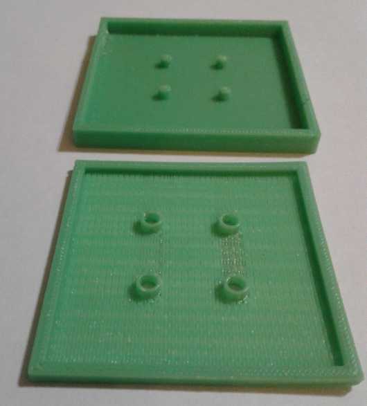 The "new ideas" flat cell, bottom and inner
porous 'shelf'.
The "new ideas" flat cell, bottom and inner
porous 'shelf'.
* The "+" current collector (with punched holes) would be placed
in the bottom with a connection tab sticking out one corner.
* The "+" electrode would be fitted into the 'dish' in the porous
inner piece, then the inner piece would be pressed into the cell,
with the electrode against its current collector.
* Then the plastic pieces would be glued together, (including the
inner posts) with a press pressing them together.
Once the "+" electrode is done and the pieces
are glued together,
the zinc "-" electrode would be placed on top of the porous divider.
Then a cover (3D printed or a simple sheet) would be glued on top.
(Hmm... a filler hole... in the cover?)
Another thing that occurred to me was the ABS isn't the
world's stiffest plastic. The thin porous face was definitely going to
bulge between the supports. PLA and nylon didn't work, but perhaps
something else might... What
other printer filaments were there?
(25th) Internet service having returned, I finally checked out
filaments. There was a new(?) one called "PVB" - polyvinyl butyral.
Unlike "PVC" it only had
carbon, hydrogen and oxygen so it should be environmentally benign to
burn for disposal, and it was said to be stronger, more rigid, tougher
(break resistant) and more heat resistant than PLA - which is itself
stiffer than ABS. And it looked from the printing parameters, similar
to PLA,
that it might not need an oven enclosure or a heat gun aimed on it
during 3D printing. (It's the plastic with which car windshields are
laminated for safety, and apparently it sticks to glass - presumably if
it's put on hot. The Wikipedia article said it had few other uses owing
to processing difficulties and didn't mention it comes as 3D printer
filament. So I added that in.)
I ordered a roll. It definitely costs more - around 5 to 7
times the price of PLA. I trust that still won't be a big part of the
overall cost of the battery. Will I have to put something on the
printer's glass bed to keep the object from sticking to it even after
it cools? Also, nothing says it's resistant to an alkaline environment,
so I'm taking a gamble on that. (I was surprised to find that PLA
disintegrates in the battery.)
(26th) I found a write-up on PVB by a company making the filament. They
seem to think PVB brings 3D printing to "a new level". It seems very
promising. Someone at one manufacturer says "PVB really is a dream 3D
printing material ..."
Here is a Write-up on PVB (long, wordy excerpt chopped mercilessly to
essentials):
https://www.mowital.com/business/news/news-einzelansicht/news/pvb-materials-are-taking-3d-printing-to-the-next-level-of-evolution/
"PVB printing filaments ... considerably
improve processes and quality in 3D printing ... compared to PLA and
ABS filaments ... while simultaneously preserving the environment."
Cupro-nickel Current Collector?
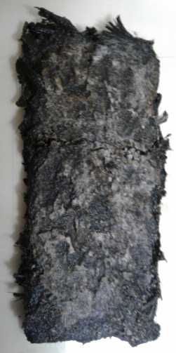 (20th) When I
was using just KCl salt for electrolyte, both copper and
nickel oxidized. It seemed I couldn't use any metal as a current
collector. In using weak KOH alkali, making it about pH 13, I noted
that cupro-nickel seemed to work and not noticeably degrade. Now I was
using a mix of KCl and KOH, but it was still about pH 13. How would
cupro-nickel fare in that electrolyte? Had I not tried that? Probably
not. It would be easy to try out in the present test cell (which I had
just abandoned because the graphite current collectors kept breaking
with the sharp bend - but had not yet thrown out), so I cut a piece to
size and put it in.
(20th) When I
was using just KCl salt for electrolyte, both copper and
nickel oxidized. It seemed I couldn't use any metal as a current
collector. In using weak KOH alkali, making it about pH 13, I noted
that cupro-nickel seemed to work and not noticeably degrade. Now I was
using a mix of KCl and KOH, but it was still about pH 13. How would
cupro-nickel fare in that electrolyte? Had I not tried that? Probably
not. It would be easy to try out in the present test cell (which I had
just abandoned because the graphite current collectors kept breaking
with the sharp bend - but had not yet thrown out), so I cut a piece to
size and put it in.
I noted that the nickel-manganates 'brick' with
plaster in it was still in one piece, even if looking rather fuzzy
around the edges. It didn't have that tendency of all the previous ones
to break into bits.
I had hoped (and rather expected) that currents would go
up with a metal electron collector, but they seemed about the same as
with the graphite.
After a few hours charging I ran a short load test, just
20 minutes. It wasn't dissimilar to previous ones with a graphite
collector. Again checking the pressure, I had a fair bit of weight
sitting on the cell, but once every minute I leaned on it. With the
extra pressure the load voltage would go up, 70, 50 ,40 millivolts. And
drop down again when I ceased. Likewise, in later short circuit tests,
without leaning on it it might yield 370 mA dropping off to 260 over 10
seconds. If I pressed my weight on it, it would hit 500 mA and only
drop to 470. Obviously the pressure, probably mainly of the brick
being pressed against its current collector, was a key factor in a
successful cell. It becomes apparent why battery makers cram every bit
of active material that can be fitted in into round cans that can take
a lot of pressure and strongly press everything together.
Cupro-nickel current collector after
several
days
of
use:
still
shiny!
I
ran and cycled the cell for a few days. Performance
seemed to be dropping. Was it the CuNi corroding? There were other
possibilities.
How was the zinc? It looked okay. But the little cover was off and the
cell was drying out. Then in the test leads, an alligator clip fell
off, and another seemed to have a bad connection. So I didn't finish
disassembling the cell to look at the cupro-nickel sheet at the bottom
that time, but
performance was still down and I did later. It looked perfectly clean
and metallic, unchanged except for a slightly more coppery color in one
area, but not as much as the one in simple pH 13 alkali. And it had run
many cycles. It worked!
That also says that the monel (or other cupro-nickel)
powder should work as a conductivity additive after all. Might it be
better than
graphite/carbon black powder? That'll be something to try out. And
maybe not so much plaster?
Another thing to try out is gold plating on the
cupro-nickel sheet. This would be only to improve surface conductivity
(and hence hopefully current capacity), the gold could be very
thin, and it wouldn't matter if the coverage had some gaps. In fact it
should be
easy to try that out in the present test cell.
http://www.TurquoiseEnergy.com
Haida Gwaii, BC Canada