Turquoise Energy News #144
covering March
2020 (Posted June 4th 2020 AD / 25 AI - After Internet)
Lawnhill BC Canada - by Craig Carmichael
www.TurquoiseEnergy.com
= www.ElectricCaik.com
= www.ElectricHubcap.com
Month
In
"Brief"
(Project Summaries etc.)
- Attributions - Bugs and More Gardening - Miles Mini Cargo Truck
- OLAHP: Open Loop Air Heat Pumping
In
Passing
(Miscellaneous topics, editorial comments & opinionated rants)
- Dimetrodon & Edaphosarus Finally Explained: Aquatic swimmers! -
Gardening and Chickens - Seaweed Shredder? - Small Thots - ESD
- Detailed
Project Reports
-
Electric
Transport - Electric Hubcap Motor Systems
* Miles Truck: 5:1 Planetary Gear replaces 40 pound transmission, much
improves performance
Other "Green"
Electric Equipment Projects
* Very High COP Open Loop Air Heat Pumping
Electricity Generation
* My Solar Power System: -
Monthly
Solar Production log et cetera - Notes.
Electricity Storage
* Turquoise Battery Project
(NiMnOx-Zn in Mixed Alkali-Salt electrolyte) - No
Report
* Miles mini cargo truck battery restoration
* Set of 144 Lithium Cylinder Cells (recovery of some cells)
I note that May 1st to 8th marked the 3rd anniversary of
my leaving my deteriorating 1879 coach house in Victoria after 40 years
and moving into my lovely new 1988 house on Haida Gwaii.
Attributions?
When people send me interesting material (generally by
e-mail) that I use or write about, I always wonder whether I should put
their name in the newsletter. I don't mean to slight valuable
contributions and not give credit where it's due. On the other hand,
perhaps some people might not want their names published in what some
might consider to be an unorthodox or unprofessional series of
newsletters. I think (after all these years) I will make it my policy
that if I haven't asked
and no preference has been stated, I will reference first names only.
Bugs and More Gardening
 Just a couple
of days into
May the first wave hatched: Blackflies. Midges. Mosquitos. Mostly
blackflies at first. Why was it I wanted warmer weather to work outside
in,
again? They and soon the "no-see-ums" continued to be a big nuisance
for the rest of the month whenever I tried to work outside. But I got
my new garden plot prepared, fenced and planted.
Just a couple
of days into
May the first wave hatched: Blackflies. Midges. Mosquitos. Mostly
blackflies at first. Why was it I wanted warmer weather to work outside
in,
again? They and soon the "no-see-ums" continued to be a big nuisance
for the rest of the month whenever I tried to work outside. But I got
my new garden plot prepared, fenced and planted.
 I didn't spend
this whole month on gardening but I pretty
much finished planting everything, and I did (more or less) finish the
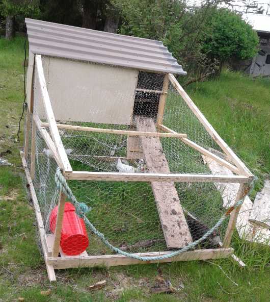
chicken sled and moved the little chicks into it. It would appear I
have two roosters and three hens. (Which rooster do I want to keep, the
white leghorn or the brown one?) After a couple of weeks they were out
foraging on the lawn and I move the sled frequently to fresh ground.
(More in In Passing)
I didn't spend
this whole month on gardening but I pretty
much finished planting everything, and I did (more or less) finish the
chicken sled and moved the little chicks into it. It would appear I
have two roosters and three hens. (Which rooster do I want to keep, the
white leghorn or the brown one?) After a couple of weeks they were out
foraging on the lawn and I move the sled frequently to fresh ground.
(More in In Passing)
Miles Mini Cargo Truck
 I spent quite
a lot of time on my electric "mini cube van"
truck. In fact, much more than I had expected. It became the month's
project, always looking almost done.
I spent quite
a lot of time on my electric "mini cube van"
truck. In fact, much more than I had expected. It became the month's
project, always looking almost done.
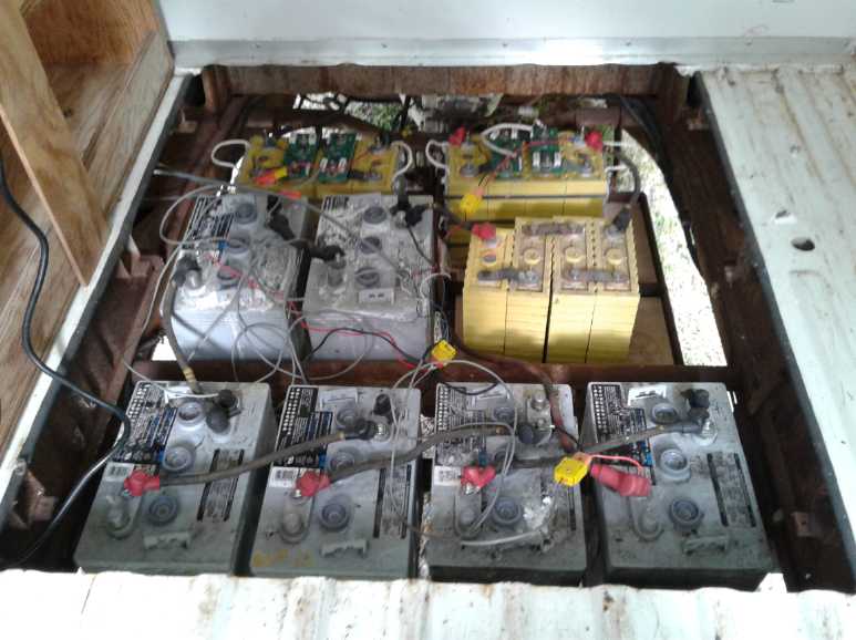
I did my best to restore the batteries, boiled completely
dry by
the truck's insane "Delta-Q" charger running at full blast for two
weeks last winter, which I had plugged in just to top them up and then
forgotten about.
Over a couple of weeks I managed to get 6 of the 12 - 180
amp-hour "golf cart" batteries going again. The other 6 still had at
least one dead cell.
I took my spare 100 amp-hour lithium battery and
two more out of the Sprint to replace them. (The Sprint is now down to
200 amp-hours, 36 volts instead of 300 amp-hours. Those should still
supply sufficient current to run it, so it's not too significant until
I have it driving nicely on the highway and want to go places. Since it
seems that may still be a while, who knows what will develop
battery-wise in the
meantime. Maybe I'll be making the NiMnO-Zn cells by then?) On the
bright side each pair of golf cart batteries weighed about 145 pounds,
and the lithium ones were 30 pounds. So the 3 pairs removed dropped the
weight of the truck by 345 pounds. It would be down 690 pounds if I
replaced
them all - not insignificant!
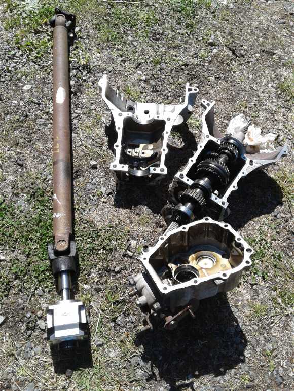
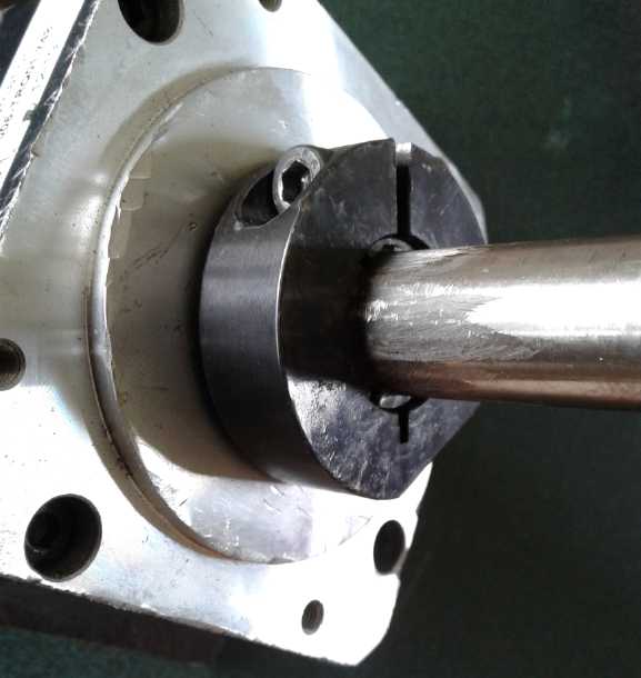
Planetary Gearbox & the
driveshaft, and the old transmission in 3 pieces.
 After I had it
running again, I decided to replace the
transmission with the little 5 to 1 planetary gearbox I bought for it
last winter. Surely that would only take a few days? I got the ~42
pound transmission out and and discovered that contrary to my
expectations of it being 6 to 1 speed reduction or higher, it was just
under 2 to 1. (There had been no simple way to determine it when it was
installed.) With the rear differential also providing 2.16 to 1
reduction, the total was only about 4.3 to 1.
After I had it
running again, I decided to replace the
transmission with the little 5 to 1 planetary gearbox I bought for it
last winter. Surely that would only take a few days? I got the ~42
pound transmission out and and discovered that contrary to my
expectations of it being 6 to 1 speed reduction or higher, it was just
under 2 to 1. (There had been no simple way to determine it when it was
installed.) With the rear differential also providing 2.16 to 1
reduction, the total was only about 4.3 to 1.
Now it made sense that
the poor truck didn't have much hill climbing ability. Essentially, it
was geared for running at highway speeds, but was limited by the motor
controller programming to 40 KmPH, so the motor was loafing along and
its available power was little utilized. The planetary gear would have
the motor running 2-1/2 times faster. If I had known, I might have
picked 4 or 3.5 to 1, so it could go faster on the highway without
over-revving the motor than at 5 to 1. It still would have had more
pick-up and hill climbing ability at low speeds than it had before. Now
it was really more optimized for lower speed city driving - and for
carrying cargo. I could also be confident of it climbing even the
steepest hills.
Most of it went well, but there was no such thing as the
right shafts to match everything. I managed to grind down the gearbox's
square key so it fit into the
drive shaft. The shaft from the motor to the gearbox was another story.
I thought I could pound a 3/4 inch threaded rod into the splined motor
tenon and the splines would "notch" the threads so it wouldn't slip.
That seemed to work, but the other end was just slightly small for the
compression fitting on the gearbox and seemingly regardless of anything
including sheet metal sleeves I couldn't get it tight. It always
slipped.
My neighbor Ron gave me a 19mm shaft from some washing
machine. That was the exact right diameter for the compression fitting
on the
gear. I roughed up its slick polished surface at that end to make sure
it wouldn't slip. But it had a spline on the other end that was just a
bit too small for the motor. I worked in a sheet metal sleeve. It
wasn't easy assembling. That lasted 300 yards, then it started
slipping. The splines had simply munched up the sleeve. I pounded in a
thin nail and managed to drive it back into
the garage and up onto the ramps, clunking all the way. I finally
thought that what it needed was two pairs of set screws through the
motor tenon and set against the shaft, two in line and two more 90°
off. I've seen that sort of arrangement to hold shafts in place before,
and the splines would prevent any possible slippage that a smooth shaft
might have. (I just hope that the front end of the shaft being a
millimeter off center doesn't make vibration. That shaft turns 10.8
times as fast as the wheels.)
That last job should have put a quick end to what had
become an annoyingly long saga, but I couldn't do it. After working
eight days under the truck, lifting the heavy assembly in and out in an
awkward position, time after time, I had done something to my shoulder.
It was in agony and I had to stop for some days.
I noticed that (when it wasn't slipping) the truck was
much more responsive. It had no problem going over tree roots in the
driveway, and the front wheels easily climbed up the ramps, where
before it sometimes needed a bit of a run at it.
When I let off the pedal, with the 2.5 times lower gearing
it was like slamming the brakes on, which force was transferred through
the shafts from the motor to the wheels like an "instant stop" power
tool. That showed up the weaknesses and loosened set screws.
The month ended with the truck still not behaving itself
and me sorry I had started this "a few days" project and finally
finding that
the left rear wheel's brake was leaking too badly to want to drive the
truck on the road anyway. Yet another job to do!
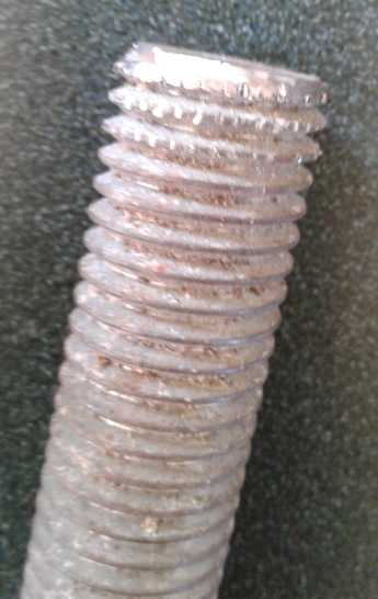
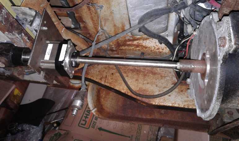 The offending shaft from the motor to the
planetary gearbox.
The offending shaft from the motor to the
planetary gearbox.
(All the space between motor and driveshaft (far left) was formerly
occupied by the inappropriately geared, heavy, fixed reduction
transmission.)
"OLAHP": Open Loop Air Heat Pumping
With the hurt shoulder I went back to studying this
subject. I learned some more and got a better feel for proportions and
what was happening in the processes of compressing, cooling and
decompressing air. In particular, if one pushes twice as much air into
a space, the pressure and the temperature both double, giving
it four times as much energy. This seems obvious once you realize it.
So the amount of air needed to double the energy is thus square root of
2, or 1.414 times as much air.
The book was about air engines, and it pointed out that as
the air cooled it lost the heat energy and pressure, so that by the
time the engine used it, it only had .707 (1 ÷ root 2) of the
energy spent in compressing it. 29.3% was thus wasted. Of course, since
it's the heat we want, we get the 29.3% and if the compressed air is
simply vented after radiating its heat away, much of the other 70.7% is
wasted. (Not quite all since the outdoor heat exchanger cools it below
its starting temperature.) Hence the low COPs obtained with regular air
compressors. Logically using the cooled but still compressed air to
help drive the compression should then roughly triple the COP over
simply venting the compressed air.
I had come up with some designs for double ended cylinders
with a piston in the middle for compressing and decompressing air, but
thinking of how little friction there is between UHMW-polyethylene and
polished aluminum I started thinking those specific materials could
make for a much simpler and easier to build ROVAC type rotary
compressor-decompressor than the original 1970s model. In principle it
was certainly an elegant concept. Now instead of complex guides and a
steel belt to move the vanes in and out, the unit could simply be spun
at an RPM sufficient to have them slide out by centrifugal force, but
not spinning so fast as to create excess drag against the elliptical
outer rim. It would also probably be reasonably quiet - quieter than a
piston type.
There is a further advantage: As already cold air is
decompressed, moisture in it can freeze out. If the exhaust port of a
slick UHMW housing faces down, the ice crystals or frost will probably
just fall out. It could potentially be arranged that they simply fall
on the ground underneath the unit if it is situated outside. (Any ice
crystals adhering to the aluminum vanes would melt again in the
compression cycle - or simply not freeze.)
Another potential improvement would be to make the inside
of the rim an ovoid (egg) shape rather than a simple ellipse. This
could be beneficial because the cooler decompressing air will have
slightly less volume than that being compressed, also because seemingly
inevitable leakages around the vanes will slightly reduce the
compression and waste a bit of expanding air.
Still another thought was that the original's 10 vanes
were surely overkill. It seemed to work in quarter rotations, so why
not 4 vanes? That would be another substantial simplification in
construction.
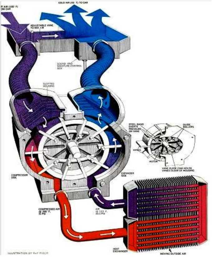
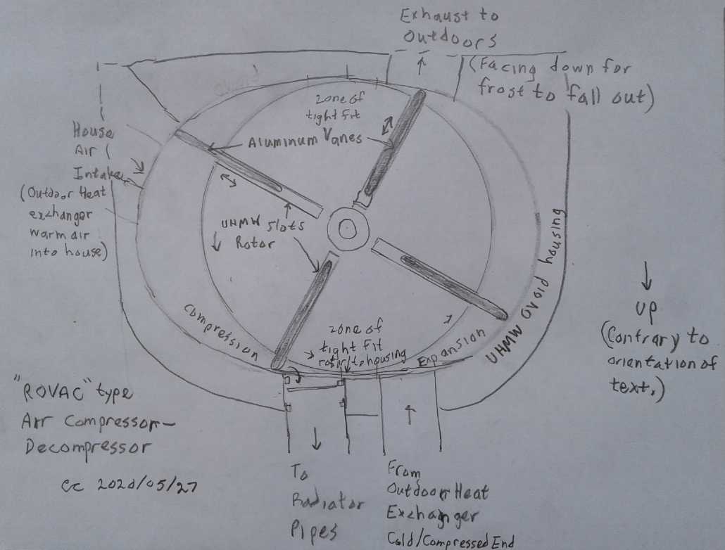 My "modern materials" version of a ROVAC air
compressor-decompressor for OLAHP
My "modern materials" version of a ROVAC air
compressor-decompressor for OLAHP
As I didn't find any "ROVAC" type compressors available
(notwithstanding a recent or current research project in India), this
would surely be the better component to develop for "OLAHP" rather than
a piston type.
I could say "When could I possibly find the time to do
this?" as with so many other potential projects, but given the impact
it could have on heating my own house next winter, I just might make
the time for it. To an extent it could be in place of making time to
cut and stack firewood.
Things are looking pretty good going forward here. I think
I'm about as well set up as I can be to weather the economic storm
that's brewing and still pursue the green energy and electric transport
work. Hopefully in June I can get back to the battery development. Then
I really should complete the model ground effect vehicle -
notwithstanding that nobody seems to be going anywhere lately anyway.
(I'm actually thinking about how to put together a full size one later
- extruded styrene foam sheets with polypropylene-epoxy skin
construction - but first, flying the model may point the way to
improvements.)
In Passing
(Miscellaneous topics, editorial comments & opinionated rants)
Dimetrodon &
Edaphosarus Finally Explained: Aquatic swimmers!
Someone commenting on a youtube video (whose name and what
video I can't remember), and noting that Spinosaurus was
evidently aquatic, may have been the first to come up with the "fish
fin" idea, in 2019 or early 2020. It made sense to me, and it fit in
with the similar "sails" of also known-to-be-aquatic Dimetrodon and
Edaphosaurus.
Now, still more new fossils of this aquatic dinosaur with
a "sail" on its
back were recovered this year from the Sahara
desert, which was long ago (and many multiple times) a swampy wetland
full of lakes and rivers. Long bones protruding upward from
the tail vertebrae revealed it had a long, tall, slender tail that was
obviously made for propulsion underwater. (BTW apparently it was indeed
a theropod dinosaur, having hollow theropod bones as well as three
toed
feet. Evidently it doesn't need to walk up on its rear legs like the
others to qualify.)

It would seem it freely went swimming underwater to catch
fish. The "sail" then is of the nature of a "dorsal fin"
such as Ichthyosaurs had, and of course as most fish have always had,
for stability underwater. But
it obviously still walked around on land too to lay eggs, and able to
travel between bodies of water. An Icthyosaur-like
"fish-fin" tail would have hampered walking.
Tadpoles and salamanders have similar tail shapes, albeit
they are so much smaller they probably don't need "fin" bones in the
tail.
This gives us the obvious explanation for the
similarly configured Permian creatures such as Dimetrodon and
Edaphosaurus.
I am still sure they were amphibians and that reptiles had not yet
evolved in the Permian period. (There are no hard-shelled egg shells
from before about the mid Triassic.) However, my idea that the sails
were to provide
extra skin surface to assist primitive amphibian buccal respiration was
wrong or at least secondary.
An examination of a few pictures of Edaphosaurus fossils
clearly shows that somewhat like Spinosaurus they had taller,
thinner swimming tails. Thus again the "sail" is akin to a "dorsal fin"
to provide stability and agility underwater. That they were fins for
swimming explains the similar form in both amphibians and repiles.
In the fossils I looked at of Dimetrodon, the thin tails
didn't seem so tall as those of Edaphosaurus, but a more vertical
form was still still evident.
It is possible that taller tail
bones simply haven't been found because of the generally poor quality
of fossils - mostly just fragments of skeletons and bones - from so
long ago. It
was long believed their tails were very short, until some better
preserved ones were unearthed. As recently as 2019 the idea the much
later (prehistoricly speaking) Spinosaurus had a tall, thin "swimming"
tail wasn't even imagined. Many scientists had concluded it couldn't be
a good swimmer.
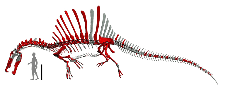 Spinosaurus skeletal reconstruction from
shortly before the "fin" tail bones finding.
Spinosaurus skeletal reconstruction from
shortly before the "fin" tail bones finding.
The red bones are actual findings. The gray parts are anatomical
guesses.
 This year's reconstruction shows the long, tall
finned tail.
This year's reconstruction shows the long, tall
finned tail.
(Hmm, not at a very good angle!
BTW there are still plenty of missing bones - no complete skeleton.)
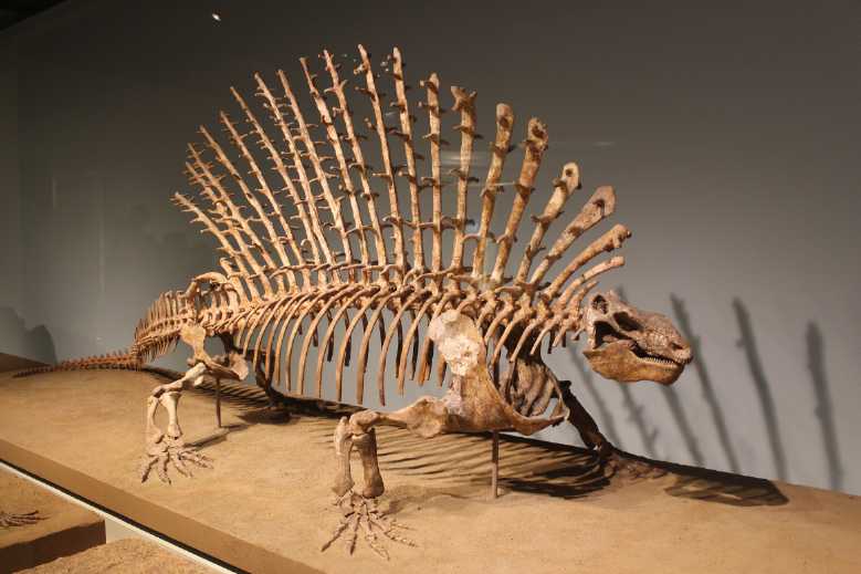
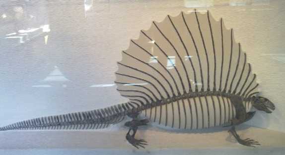 The tall, thin swimming tail of the Edaphosaur
is evident in these skeletal reconstructions.
The tall, thin swimming tail of the Edaphosaur
is evident in these skeletal reconstructions.
The bone protrusions in the "dorsal fin" (upper image) probably
attached muscles related to swimming.
The vertical forms of the tails evident in the skeletons
doesn't carry
over into most artists' renderings of these creatures, in which they
are
usually depicted on dry, open ground, and with a round tail - yet with
the bone
microanatomy saying "aquatic". It shows
how much the artists' renderings depend on
their perceptions of what the animal was, at times even to
ignoring features of the actual skeletons upon which these assumptions
are based.
 This very early drawing of a Dimetrodon shows a
'swimming', rather alligator-
This very early drawing of a Dimetrodon shows a
'swimming', rather alligator-
like tail form (and webbed feet) much better than more recent ones.
But the belief that it was a land dwelling reptile rather than a large
salamander (based on expectation rather
than evidence) shows through clearly in the "scaly" instead of smooth,
moist
skin texture and especially in the
"skeletal" sail, which actually must have been fleshed out to be
smooth and streamlined in the water.
We may part with thoughts that perhaps Dimetrodon tail fin bones simply
haven't been discovered yet, or the creature being smaller than
gigantic Spinosaurus, perhaps they were made up of cartilage that
didn't fossilize, and also the possibility that Dimetrodon also kicked
its webbed back feet like a frog to help propel it through the water.
It must be remembered that in those distant times, seed
plants had
not yet developed and there would have been little food to base an
advanced dry land ecosystem on. Dry land creatures were initially
limited to
arthropods - scorpions, insects, millipedes and so on - some of which
grew to enormous sizes. The larger ones would die out as seed plants
developed and more advanced animals colonized dry land.
I think that seeing such "giant salamander" creatures in
the flesh, swimming through the warm pools and swamps of that time and
crawling out onto the land, would have been an astonishing sight.
Gardening & Chickens
I soon noted that the wheat, Kamut and Red Fife, had
sprung up. I have high hopes for the Kamut. The kernels are much larger
than the other types so it will be easier to process with a blender,
hair dryer and coffee grinder if I grow enough of
it to actually use, and it is said to have a "corn-like" flavour. (Red
fife: "nutty" flavour.) I didn't like the "Alaska Spelt" because the
seeds came with the husks
still on and they seemed very difficult to peel off. That's probably
okay if you have automated equipment. And I got a fence around the new
plot. Some
deer was already trampling through it repeatedly. Soon enough it would
be eating
things.
Someone was criticizing my gardening methods. I'm doing
what seems to work around here. I decided "no dig" was great for
established beds, but I found last year that if I didn't get the mass
of roots out of the new bed the weeds would completely take it over
again during the winter. And even if I had scratched out the
muskeg-like upper mass without digging out the fern roots a few inches
down, it would have soon overgrown with ferns. Grass mulch is great
except I found it attracts or hides slugs, which keep eating all my
seedlings before they get a chance to grow much. It's disheartening to
see a promising young plant growing well one day is missing its leaves
or is lying loose on the ground separated from its roots the next day.
(And (gasp!) mice ate my 45 $ worth of slug bait!) Most of the
gardening ideas were probably good depending on climate and conditions.
I liked grass mulch in Victoria.

 I am thrilled with this new long-thin-blade
shovel!
I am thrilled with this new long-thin-blade
shovel!
One can dug a deep post hole or a trench removing far less dirt than
with a typical wider shovel.
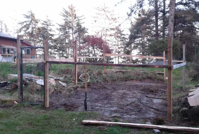
Seven posts and six long boards to help keep them upright
(The cross bracing boards idea came from a youtube gardening video)
I wrapped about 90 feet of a 100 foot roll of 5
foot tall fence wire around it all.
That should keep out our small island deer. (3 staples so far. Must add
a few more!
I got the metal gate from the dump station a year ago. Finally I've
used
it.)
 The corn I
grew in cloudy, cool 2019 was a wipeout. The tallest
stalks only grew tassels to barely chest high without a ripe, edible
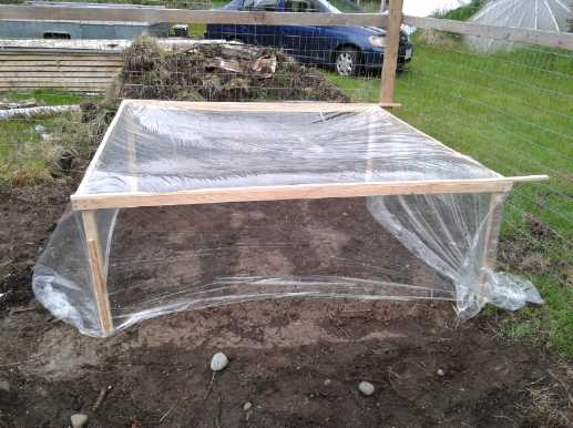
kernel anywhere by fall. This year I've tried putting plastic over them
to help them start out in early spring, and planted them against the
south wall of the house.
The corn I
grew in cloudy, cool 2019 was a wipeout. The tallest
stalks only grew tassels to barely chest high without a ripe, edible
kernel anywhere by fall. This year I've tried putting plastic over them
to help them start out in early spring, and planted them against the
south wall of the house.
In a store looking for other seeds I saw packages of corn
seeds: "Peaches and Cream Early". It sort of registered, but it wasn't
until later that I thought "Wait a minute! The growing season is too
cool and too short, and I'm
growing regular season corn? There being nothing called "Cool Season
Corn", why on earth should I be trying anything but "Early"? By the
time I went back to that store again it was early May, and the corn
moved out of seedling pots into the ground was 6 inches high. They
still had some of the seeds and I decided to start a flat of the
"Early",
indoors, anyway. Boom! They germinated in a couple of days. Maybe by
the time to put them out I would have made a
decent plastic frame that the wind didn't blow away?
I put them down in the new
plot. The frame I made was good, but the packaged sheet of plastic I
found was so thin it was soon badly ripped up. How long had this
useless package of plastic been sitting around this house? No web site.
No bar
code. Price printed on the package in felt pen... followed by a
"¢" sign! The price gave an idea
of how long it must have been sitting around (and how much everything
has gone up):
 The thin plastic "protecting" the corn has
shredded badly.
The thin plastic "protecting" the corn has
shredded badly.
Yes, this was once a typical price for a small item. Early 1970s?
(The "$" sign traditionally goes on the left instead of the
right because "¢" was the more common unit. $0 49¢)
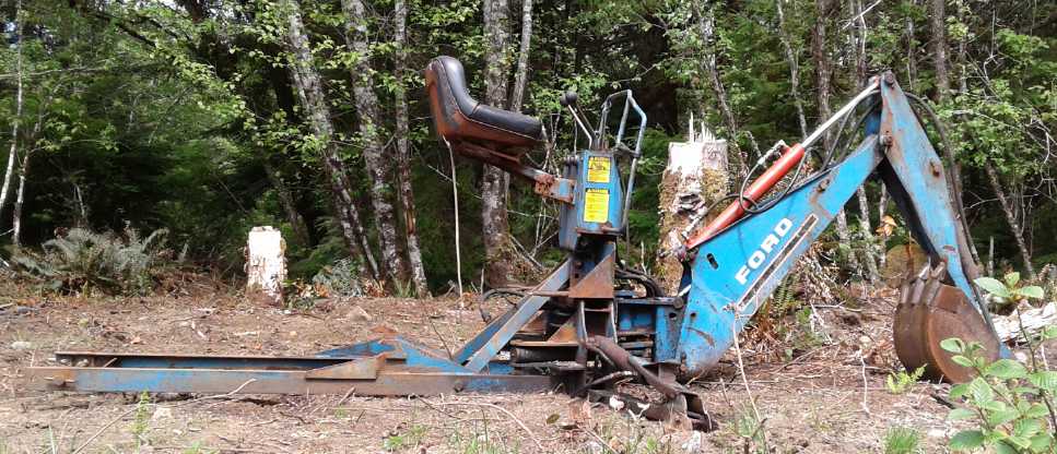 Last month I wrote of my neighbor having
a small
Last month I wrote of my neighbor having
a small
backhoe attachment for his tractor. Remarkable!
I didn't get a picture of him using it in April, but I
saw it sitting at his place in May and took this one.
 Penthouse Suite in the chicken sled. (Nesting
box is off to the left at close end.)
Penthouse Suite in the chicken sled. (Nesting
box is off to the left at close end.)
It's not very big. I planned to just have 2 or 3 hens, but having to
buy "unsexed"
chicks you want to get enough to be pretty sure you do get those hens.
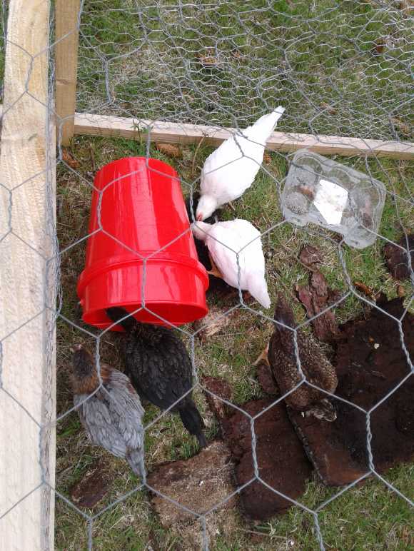
Five 7 week old chicks
The whole chicken sled at the end of the month.
I move it frequently. The chickens scratch around
for bugs and weeds, and the chicken feed
consumption seems to have
dropped.
(It's pretty light but I think wheels would be an asset.)
Seaweed Shredder?
Being in an opportune location for it, I had been getting
seaweed from the beach in buckets as garden fertilizer - eel grass,
kelp, some sort of polyps and so on - whatever was there, mostly in the
spring before planting. I mostly took
dried out material lying along some high tide line. I figured it had
mostly the same minerals as the freshly washed in stuff but it was all
shrunk down - both more concentrated and lighter to carry. However, wet
or dry it's like a mass of strings. You can bury it with a shovel, but
then when you rake the ground it catches and you pull big wads of it up
again. So much of it is always on sitting top instead of mixed into the
soil, and being up there it doesn't rot and blend in its nutrients. The
handheld rototiller somewhat chops it up, but it winds around the tines
and clogs it up.
I figured what was needed was some sort of
giant "Vegomatic", maybe 18 inches square, with criss-cross blades and
a plunger, to cut it all into little squares. Probably with long
handles
for leverage to push the stuff through. (Either that or make it to be
hammered down with a maul.) Heavy steel blades.
A doubtless more practical (easier to make) version could
have blades just going one direction. After pushing a clump through,
turn it sideways and do it again to get squares.
Later, on trying to slice through a mat of it with a
sharp, flat end shovel, it was almost impossible - too tough - and so I
don't think the "vegomatic" approach would work well. unless it was very
heavily built.
Perhaps a better thought would be to make the plastic
shredder for
recycling plastic instead. That could equally shred seaweed, and it
would be much finer! It could perhaps even be a "money maker" for
someone who wanted to sell shredded seaweed for organic gardeners. (And
it'd shred plastic as well for remanufacturing! Ooh, aah!)
Oh wait... the seaweed usually has wood bits, sand and
sometimes small rocks in it. That might be a fast way to wear out
plastic shredder blades.
Back to square one!
Small
Thots
* According to "Epic Economist" channel on Youtube, UN world food
program executive director David Beasley has warned that we are facing
the "worst humanitarian crisis since world war two." He says that we
could soon see 300,000 people starve to death every day over a three
month period. This estimate didn't even include any extra owing to
economic
problems caused by the CV19 pandemic. Unfortunately it wasn't clear
whether this was in India, Africa or both, but I've seen ads pleading
for people to send money for food to India.
In the USA, people are lining up for hours - in nice cars
- at food banks. Those arriving too late get nothing. It would seem
shortages, and poverty, are spreading. Perhaps some of those people
would have sold their cars to have grocery money, but the bottom has
dropped out of the used car market.
* In the 1930s Hitler's SA, SS and gestapo murdered and tortured many
people.
One could not turn to authority for justice when the police were the
criminals with sanction from the highest levels. Stalin's Russia was
probably worse. In the 1970s Pinochet overthrew Chile's president and
suspended human rights, and his thugs burned books and
"disappeared" 30,000 people - those in power feared anyone who dared
speak up or who entertained thoughts for improving society. The active
and idealistic young were special targets.
Now in the USA a policeman stuck his knee into an unarmed
man's neck on the ground, suffocating him. Three other police stood by.
Bystanders were
not permitted to give aid. He died. Apparently he had passed a
counterfeit 20 $ bill. There is a lot of counterfeit money in the USA,
so without knowing more of the story, one can't be at all sure he did
it knowingly.
(Interestingly, according to a nightclub owner, both the
victim and the killer had previously worked security at his
establishment, but probably(?) hadn't known each other.)
In any of the above mentioned
states and times, and in many previous complaints about this same
police officer's violence, it would have simply been presumed (by the
authorities) that the officer must have been doing the right thing, and
there would have been no action or investigation. The difference?
This one was caught on video and made it onto the internet. It seemed
clear that the officer and his companions had used entirely
unwarranted force with no compassion or mercy and with utter distain
for human life.
The outrage led to protests and violent uprisings in various cities
across
the nation. Could a brutal dictatorship where such things were routine
establish itself in North America or Europe in this day and age? I
wouldn't say no, but I hope it
would be substantially harder. Even Hermann Goering was taken aback at
the Nuremberg trials when films were shown of concentration camps and
the
suffering caused by the anti-Jewish program he had played such a
leading part in.
* Someone once said something to the effect that riots are
the voice of those who have no voice. The gross inequalities in western
societies are coming home to roost. Someone else has said that rule of
law has been gone for years in "upper" circles. It started with the
"sub prime mortgages" (whose crazy idea?!?) which ended in the 2008
debacle where banks essentially stole something like 1/3 of America's
wealth and real estate from people everywhere. Rule of law didn't
apply to them. No one went to jail or even lost their job, and the
government didn't
make the banks give back or give up all that ill-gotten real estate.
(for which the banks were double paid: they got the mortgage insurance
money plus the houses, with all that had already been paid off the
mortgages.) They simply kept it off the market, often vacant, to
prevent property
prices from dropping back to a natural level. With the above spark now
lawlessness is descending from the rich and powerful to
levels of the general poverty stricken public owing to the pent-up
anger of so many who have lost everything with so little hope of ever
getting anything back.
* Some economist on Youtube in a video titled The Government is
Broke said that the USA owes 20,000,000,000,000 (trillion) dollars.
Then he said that if you went into every country, and into every store
in each country, in all of Europe, and bought everything off every
shelf, you'd have spent about
that amount. Then he said that with all the government's unfunded
obligations (pensions, food stamps, and so on), the actual debt is
around 140 trillion. (And I've heard others give figures in the same
ballpark.) Tax revenues are grossly inadequate. There is no
way to pay it except to inflate the money supply, stealing the value of
everyone's savings. (And in my opinion and that of many others, and
with all the currencies linked together, at this point that's going to
end rather soon in hyperinflation - the devaluation of all fiat
currency
to zero.)
ESD
(Eccentric Silliness Department)
* Hitler's favorite alligator has died in a Moscow zoo, age 84.
* My "pullet surprise" chicks seem to be two roosters and three hens.
Pessimists' Club
* Every silver lining conceals a dark cloud.
* Murphy was an optimist thinking one might get as far as a
demonstration before something went wrong.
* Philosophers may debate whether the glass is "half empty" or "half
full", but whatever it is it's probably stale by now if not utterly
rancid.
* If alcohol, tobacco, cocaine and marijuana are such bad drugs, why do
people
lose so much more sleep over coffee?
* Pronunciation debate settled: With the ambiguity of English spellings
people have long been confused whether the "Celtic" people were
actually called "Kelts" or Selts". The "C" is actually pronounced the
same as in "cycle" or "concert".
* The ones from Wales were probably Welts.
* Pooey, the right front door on my Toyota Echo won't unlock or open!
(Jiggling the lock lever while repeatedly pulling the inside door
handle has quit working.)
SIDE DOORS - DISASSEMBLY AND REPAIR INSTRUCTIONS
1. Unlock door and open it wide.
2. Undo screws from.....
"in depth reports" for
each project are below. I hope they may be useful to anyone who wants
to get into a similar project, to glean ideas for how something
might be done, as well as things that might have been tried, or just
thought
of and not tried... and even of how not to do something - why
it didn't
work or proved impractical. Sometimes they set out inventive thoughts
almost as they occur - and are the actual organization and elaboration
in writing of those thoughts. They are thus partly a diary and are not
extensively proof-read for literary perfection, consistency,
completeness and elimination of duplications before
publication. I hope they add to the body of wisdom for other
researchers and developers to help them find more productive paths and
avoid potential pitfalls and dead ends.
Electric
Transport
Miles Electric Truck: New Planetary Gearbox
(I got the batteries working or replaced in the first part of the
month. (See under Electricity Storage) Then I decided I might
as well put in the planetary gear I bought to replace the transmission.
A short, simple project... Ha Ha!)
What am I doing with this little electric cargo truck,
anyway? I haven't had a real use for it so far. The paint is crappy so
it's rusting unless it's taking up a garage, and it's not worth
insuring it at this time.
I just have this
feeling that it'll be much wanted during some of the coming hard times.
Haida Gwaii is at the end of a long, tenuous supply chain.
Infrastructure here was late developing - someone said the paved
highway was only
finished in (?)1979. If gasoline becomes scarce for a while, a few
electric vehicles and bicycles may be the main things running.
But the Nissan Leaf requires so much power to charge that
it may be a problem: no petroleum, no mains power. It's not a question
of charging slower. Its lowest charger wants 1500 watts from a 120 VAC
plugin, and if it can't get it, the charger just chokes and it can't be
charged at all. With over 300 volts potential, and even then a computer
that probably won't recognize if it's been charged by some outside
means, it's not something I care to try and "hack". Realisticly 1500
watts is about eight or nine 305 watt solar
panels in the sun at good angles on a sunny day, all connected in
parallel to feed
(eg) my 2500 watt, 36 VDC to 120 VAC inverter - and perhaps taking days
to charge the car depending on its state, the sun and the time of year.
(November, December and January could well be entirely problematic.)
The truck, especially with three solar panels on the roof,
will charge however fast or slow the sun lets it. I'm pretty sure it
will use less power than the Leaf with the new gearbox (and lighter
batteries). Travel speed being below regular highway speed will improve
economy and (presumably) it won't matter much as long as it can deliver
cargo.
A big discovery from doing the project is that contrary to
my expectations of it having a very large gear reduction, the original
transmission was only 2 to 1. With the differential's reduction that
made only ~4.2 to 1. That explains why the truck seemed to have not a
lot of torque. Its hill climbing ability was poor. Even at 50 KmPH it
would be running the motor at just 2100 RPM - less than half its rated
continuous speed. So it was really geared for highway speeds, but was
limited by
the motor controller programming to 40 KmPH. (If I had realized that, I
might have chosen a 4 to 1 or 3.5 to 1 planetary gear to allow
higher speeds yet still improve torque.)
So dumping that low ratio transmission and changing to the
5 to 1 planetary gearbox (10.8 to 1 total reduction) has an unexpected
effect of greatly improving the performance at the lower speeds for
which the truck was intended and for carrying heavy cargo.
People have asked me if that little 7-1/2 pound planetary
gearbox is big enough. It's sure small and light compared to the
original 42 pound transmission. I reply that the torque and RPM specs
looked good enough. About 200 foot-pounds (admittedly minimal) and 8000
RPM. It won't ever be going half that RPM (and I suspect that will
increase the allowable torque somewhat). A mechanic said planetary
gears are
enormously strong. But in truth I do wonder myself if maybe I shouldn't
have gone up a size.
(14th) Having got the truck running again by battery renewal and by
replacing half of them after the Truck's "Delta-Q" charger boiled them
dry last winter - charging them at its maximum power for around 2
weeks, somehow
in preference to any other building project, I decided to go for
putting in the small planetary gearbox I had bought last December to
replace the doubtless "typical" lossy transmission in the truck. (with
only one gear ratio installed anyway.)
It should be simple, right? Just a little project, a few
days? I drove it back into the garage and the front wheels onto ramps,
which gave me enough room to work under it.
I spent 3 hours getting the ~42 pound transmission out. So
far so good. Then I thought I would probably want the splined front
shaft that fit into the motor shaft's splined tenon, so I spent a
couple more taking it apart and extracting the shaft. But the way it
was made it seemed
problematic to attach anything to the other end.
I recall when I was driving the truck around Victoria,
getting it up to 50 KmPH, it sounded like it was screaming away, and I
assumed the motor had a very high reduction ratio through the
transmission and was headed toward its 10,000 RPM 'intermittent' rated
top speed. (It only went that fast once or twice near the beginning,
when the sensor was malfunctioning - it wouldn't go much above 40 once
it was working right.)
But when I got the transmission off the truck, opened it
and checked, I discovered that the reduction ratio in the transmission
was in fact only ~1.95 to 1!
Last October/November I had figured out that the reduction
ratio of the rear axle differential was 2.16 to 1. That meant the
overall reduction from motor to wheels was just 4.21 to 1! The howling
noise must have been from the transmission gears then, since the Curtis
AC34 motor would only have been going ~2100 RPM at 50 KmPH -- less than
half its 5000 RPM continuous rated speed.
So those who made the truck had really done it "out of
whack". It had poor torque because of the low ratio, and yet it was
artificially limited to 40 KmPH so it couldn't go high speeds. It
wasn't making good use of the motor's power capacity by loafing it
along. I had assumed 5 to 1 would be lowering the reduction ratio, but
it was in fact multiplying it by 2.5! Still, with the new ratio of 10.8
to 1 the motor will stay under 5000 RPM until almost 50 KmPH, and I
expect it will really handle to 60 KmPH (~6480 RPM), if not 70 KmPH,
fine.
The truck should perform much better. Greater torque will
be wanted if it's carrying a heavy cargo. And there's a hill in Queen
Charlotte I doubt it would have gone up even empty. I wasn't confident
of getting back up my driveway, either, especially if the batteries
were low after a trip. With the greater reduction it should have no
problems.
I'm glad I have the Curtis motor controller programmer and
should be able to change the parameters to match what I'm doing.
So... I had the transmission out. The jobs to complete the
project are:
1. Match the planetary gear output shaft to the drive shaft. They fit
so closely that I think it will be a matter of 'cludjing' it by
grinding/filing the square key on the gear so it fits tightly into the
splines in the driveshaft and won't slip. (Without the grinding the
shaft with the key won't quite go in.) This should be pretty easy.
2. Mount the planetary gear in position for those shafts to match up
and connect. This will be harder.
3. Make a very straight shaft that fits the motor on one end and the
planetary gear input on the other, of the length to connect them. This
will be tricky.
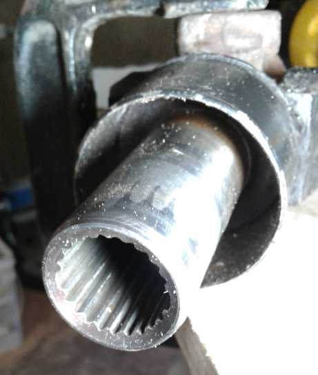
Driveshaft with "missing"
splines - a place to put in a shaft key
 (15th) I started in on the
first job and decided it was just a bit too
loose and needed a thin sleeve. I cut a thin piece of nickel-brass, but
it was too thick. I hammered it thinner, annealed it with a torch and
did it again. This time it almost went. Now I hammered them together,
wincing somewhat at the stress I must be putting on the bearings.
(15th) I started in on the
first job and decided it was just a bit too
loose and needed a thin sleeve. I cut a thin piece of nickel-brass, but
it was too thick. I hammered it thinner, annealed it with a torch and
did it again. This time it almost went. Now I hammered them together,
wincing somewhat at the stress I must be putting on the bearings.
The driveshaft and planetary gearbox,
and the original transmission in pieces.
I found a piece of 3/16" steel to use for a mounting plate
and cut it to size using up a zip disk on the angle grinder. Now it
needed bolt and mounting holes cut out for the planetary gearbox, and
bolt holes to attach it to the frame of the truck. (The truck had a
couple of existing mounting holes with welded on nuts.) And the hard
part would be bending this plate steel piece 90° into an "L" across
a 7 inch width. The transmission had a rubber mounting attached to that
to lessen vibration and noise. Did I need that? I decided not to bother
and see how it was.
There was an 80mm mounting ring on the gear. The hole
should fit around that. But there was a catch: with the gear and the
driveshaft together, an 80mm hole wouldn't fit over the far end
assembly of the driveshaft to slide down to the gear end. I put a fat
slot through the plate for the thin part of the shaft to pass through
to the 80mm circle.
(16th) The shaft from the motor to the gear turns 10.8 times faster
than the wheels, with 1/10.8 times as much torque. 250 foot-pounds at
the wheels would be just 23 on the motor shaft. My original thought had
been to use a piece of 7/8" 4140 HTSR steel machine shaft. But it had
to fit at both ends. A 3/4" bolt seemed to almost jam into the splined
motor tenon. That gave me the idea that if I had 3/4" threaded rod,
which was softer than
the bolt, I could pound it in and it probably wouldn't slip. That was
also the right size for the input tenon on the gearbox. I didn't have
any 3/4" rod and the hardware store was still closed, but that was what
it needed.
I also dropped by the refuse transfer station. There were
a couple of adjustable brackets. I didn't need a bracket, but I did
want one of the pieces of 2" x 3" angle iron they contained. I
could attach it to the truck, then my steel plate to that, and not have
to bend the steel plate. That would simplify things.
(17th) Cutting the welded parts off the angle iron piece used up a
couple of zip disks. With a couple of bolt holes it seemed to fit well
on the truck.
Then I went to my neighbor's and bummed a piece of 3/4"
threaded rod off him. He had one, in the last space of what he said was
the very last place we could look. Then I spent an hour there showing
him how to use a machine lathe to resurface his trailer brake drums.
(Someone had given a great machine lathe to him in exchange for work,
but he had never used one.) I was pleased to be able to pay him back in
this way for preparing up my garden plot and for the piece of rod.
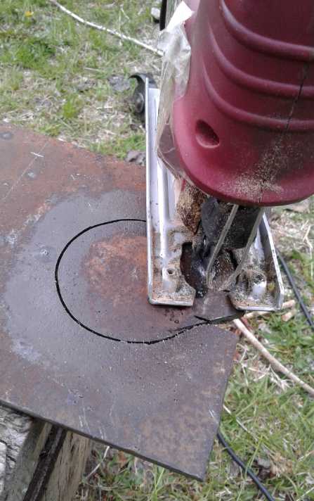 Cutting the
80mm circle from the plate steel with a jigsaw was
(as expected) tedious and time consuming. I had carefully laid out the
holes for the four bolts through the gear face, but the oil from the
cutting wiped the markings off. I put the gear in the hole and used a
pencil through the actual holes to mark for the bolts. They were all
substantially off even when I drilled a size larger, and I had to file
them all to ovals in one direction or another to get the bolts through.
Cutting the
80mm circle from the plate steel with a jigsaw was
(as expected) tedious and time consuming. I had carefully laid out the
holes for the four bolts through the gear face, but the oil from the
cutting wiped the markings off. I put the gear in the hole and used a
pencil through the actual holes to mark for the bolts. They were all
substantially off even when I drilled a size larger, and I had to file
them all to ovals in one direction or another to get the bolts through.
(18th) I noticed
that on the driveshaft's tenon a couple of the splines were omitted,
making notable slots. I trimmed down the key for the gear shaft until
it fit into one of these. Then I pounded it back together again. I
don't think that can slip. Then, needing a smaller plate (owing to
finding the angle iron piece), I cut it smaller. (Yet another zip disk!)
 I
cut the threaded rod to length. Then I pounded it into
the tenon on the motor shaft. As I had hoped, the splines in the tenon
cut little notches into the threads in the threaded rod to hold it from
slipping.
I
cut the threaded rod to length. Then I pounded it into
the tenon on the motor shaft. As I had hoped, the splines in the tenon
cut little notches into the threads in the threaded rod to hold it from
slipping.
After a few other nuisances
and readjustments, I put
everything together under the truck. The other end of the threaded rod
at the gearbox, from which I had expected no trouble, just slipped. It
was a "taper lock" type compression fitting with no solid splines or
keyslot. I tightened the screw more and more, finally hammering on the
Allen key to tighten it more, but it didn't fix it. The key was
starting to strip and the socket bolt in the gear might be no better.
(The truck did now actually move, but it was still slipping. I probably
could have driven it off the ramps, but that would only mean I'd have
to work under it right at ground level.) I guess the threaded rod was
just a bit too small diameter and would need a sleeve. Let's see:
socket, 19mm. shaft, 3/4" or 18.35mm. But probably even smaller being
threaded. Ug!
So the truck didn't run on the 18th. It also needed some
rubber vibration stoppers on the bolts holding the gearbox plate and
angle bracket to the truck, but I'd have been happy to drive it around
the driveway once even with the plate rattling.
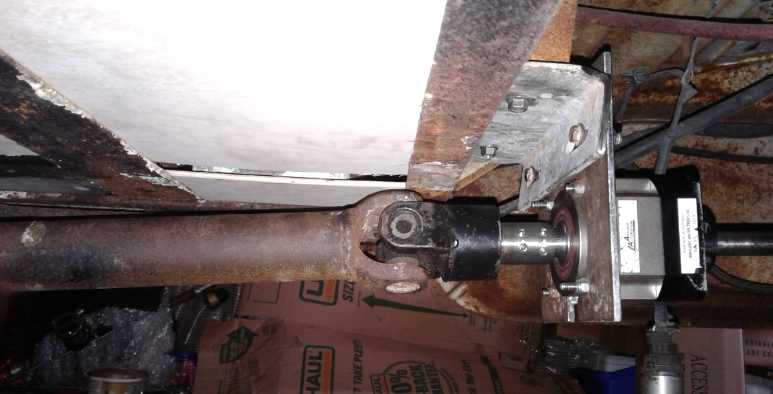 Planetary gear mounted with plate and
angle iron
Planetary gear mounted with plate and
angle iron
(shafts are as later configured - still later thick rubber
washers were
added to the mounting bolts for cushioning)
(19th) I disconnected the (3/4" threaded) motor shaft from the
planetary gearbox. I made a sleeve but couldn't get it in. I pounded it
thinner and still couldn't. Then I took a file to the threads and filed
them down a bit. Then I managed to get it started, and I used a hammer
on the other side of the gearbox to work the shaft in to its proper
depth. Then I tightened up the locking screw and clamp. I got in the
truck. It still just slipped. I put visegrips on the allen key and
really torqued it in. (It's only a poor little ~m5 socket bolt!) This
time it seemed to hold. I backed the truck off the ramps and out the
garage door, but as soon as it hit a bump it started slipping again,
and wouldn't move. I crawled under and torqued it down until the allen
key stripped. It still slipped. This gearbox is supposed to be rated
for that sort of torque - it wasn't even that much. If it's that hard
to get the grip with a compression fitting, why would it not have a key
or splines? Now what? I pushed the truck back into the garage and
closed the door.
After a bit I thought that maybe it could get a better
grip if the clamp wasn't fully closed up to the gearbox. I pried the
clamp away. Now I could turn the motor & shaft by hand - it slipped
freely. Then I realized what was happening: the clamp was tightening up
fully until its slot was closed. Then of course it could tighten no
more, no matter how hard I turned the screw. In spite of my sleeve, the
shaft was still a little too small.
By this time, after days of crawling under the truck, I
was feeling somewhat crippled. My left shoulder and upper arm ached and
burst into pain if I moved it the wrong way.
(20th) I tried inserting thin steel shims, but the results didn't
inspire confidence. And after backing the truck out of the garage, I
stepped on the electron pedal a bit harder and it started slipping and
spinning again. I pushed it back into the garage. In fact, once again
it was so loose I could turn it and slip it by hand.
My Neighbor Ron
had a washing machine shaft whose end he said looked similar to the
original splined shaft. On close inspection, verified by a micrometer,
it wasn't quite the same. However the smooth end was 19mm - the exact
proper size for the compression-fit gearbox end. Now during disassembly
the pounded-on driveshaft slipped off of the gearbox shaft just by
gravity!
I came up with a new plan. I could cut the original
splined shaft off and machine it so there was a short 19mm shaft end
and fit the splines into the motor splines, and use a piece of the
smooth 19mm shaft at the gearbox end. (I would rough up the surface to
help ensure it didn't slip.) Connecting those I would need a piece of
steel pipe machined to 19mm I.D. at the ends. This could have a couple
of pins or bolts with nuts, right through the pipe and shaft at both
ends to ensure they couldn't slip. It would be a three piece shaft.
Since it seemed I couldn't stop the threaded 'ready rod' from slipping
at the gearbox,
this sounded like a more workable plan, and I would feel more confident
having the original splined shaft end in the motor.
Hmm... Maybe instead of a pipe I should buy a 3/4" keyed
shaft coupler. (If I need to I can bore that out to 19mm on the lathe.)
(How *do* they cut those inside keyslots, anyway? ...And inside
splines?)
 (21th) I got the threaded
rod out of the motor shaft by screwing a nut
all the way on until it was turning against the motor shaft socket. I
tried the splined shaft, even knowing it wasn't the right spline. It
seemed to fit solidly enough anyway... just trying to turn it by hand.
I cut
the shaft to length.
(21th) I got the threaded
rod out of the motor shaft by screwing a nut
all the way on until it was turning against the motor shaft socket. I
tried the splined shaft, even knowing it wasn't the right spline. It
seemed to fit solidly enough anyway... just trying to turn it by hand.
I cut
the shaft to length.
After I roughed the polished shaft up to help keep
the gearbox end from slipping, I had to pound the 19mm shaft into the
19mm opening intended for that size. I did up the clamp bolt quite
tight, but without hammering on the allen key. Hopefully that
wouldn't slip! Eventually I got the whole thing together and tried it.
The splined shaft in the motor tenon just spun freely. So much for my
"by hand" assessment and wishful thinking that it wouldn't. I could
either try with a sleeve or go for the two-coupled-shafts idea. The
sleeve was of course the easier and worth a try. But I was really
getting tired of this whole exercise in frustration. If I
could just go into some store and buy a shaft coupler I'd probably have
gone for that. But I didn't want to order one and then wait for it to
come.
And I didn't want to spend time turning shafts and milling keyslots.
(But it turned out that might have been faster!)
This project was supposed to be done days ago! It was
getting frustrating. At 10 PM I cut and curled up a sleeve piece and by
11 I had managed to get it in place. It formed to the shape of the
splines and it worked. I drove the truck a foot forward and back in the
garage, and I pressed a little extra on the pedal and it didn't slip.
But to what press on the pedal, and for how long? I didn't really trust
it farther than I could throw it.
(22nd) I drove around the driveway in the morning. The truck was very
responsive to the pedal, and I didn't have to push it half so far to
get acceleration from a stop. It easily climbed over a tree root on a
rise that had stopped it when I was testing the batteries (albeit with
poor battery power). It was definitely an improvement. So I decided to
drive across the acreage and back. I got around back and there was an
obstacle. I took my foot off the pedal and the sudden very heavy
braking torque
(multiplied by 2.5 times!) must have bent or squished the sleeve. Once
again it just spun. (Great!
Now it was blocking the drive at the narrowest point.)
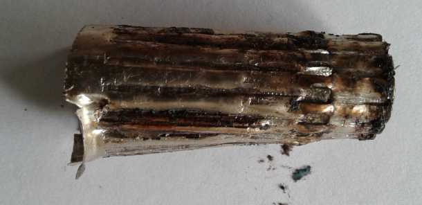 The lacerated sleeve let the shaft & socket
just slip.
The lacerated sleeve let the shaft & socket
just slip.
(Somehow not obvious: many of those indents have or are actual air
gaps.)
I decided to try
driving some bit of metal into the join to see if I could get it to
move again. I found a nail. It wouldn't pound in very far and only got
me 40 feet before it fell out. I found & pounded in a couple of
smaller ones, and managed to drive it back into the garage - and even
back up onto the ramps - clunking all the way. (But with the new 5 to 1
planetary gear it went easily up onto the ramps, whereas before it was
dicey whether it had the 'oompf' to go up them without taking a run at
it.)
Another idea had occurred to me in this: sometimes shaft
sockets have setscrews put in at right angles to grip the shaft inside.
The tenon seemed plenty thick to hold set screws. I could put in four,
two in line and two more at 90° to that. Since the shaft inside was
splined (and the contact points could be ground down a bit),
the setscrews wouldn't just slip around the shaft. This of course meant
taking it apart again. And then getting underneath to drill and tap the
holes. I was really getting sick of this project. At least the
compression joint, and the driveshaft, didn't seem to be
slipping or clunking.
(24th) I not only had other things I had to do, but my arm hurt too
much to consider crawling under the truck again for a few days. All -
presumably - within an ace of having it running well. Now 10 days of a
project I had hoped might take 3 or 4.
I spent two nights in agony with no sleeping position
where my upper arm wasn't in pain. I reached over with my other arm and
started feeling out the sore spots around the back of the "ball and
socket" shoulder joint. Finding sore spots and pressing on them a bit,
moving the finger around a little, seems to do wonders for many soft
tissue injuries. The next three nights got better.
(27th) I unthinkingly lifted the heavy end of the chicken sled and my
arm exploded into pain again. It didn't seem to last, but I thought I
might not be ready yet to resume. The day was fine. That evening I
drilled just one of the holes, but that night I woke up with my arm in
considerable pain again. Was it the day's stresses, or did I just twist
the wrong way sleeping? Yikes! (I thought this was about a truck
project?)
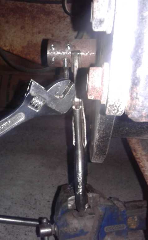 (28th) I
decided I just had to finish this up. Over the course of the
day I drilled and tapped the four holes and put in set screws. (I hung
a visegrips and on that an actual vise, to keep the shaft from spinning
while I worked. I had to turn the tap with a crescent wrench because
the motor body was in the way for the regular 2-ended tapping handle.)
One at a
time and I gave myself lots of rests, but my shoulder was aching again
before I was finished. I put two set screws in each position to hold
the shaft along the length of the coupling. As the shaft was splined
and it couldn't slip if the set screws simply pressed a couple of
splines between three other splines (although mismatched) on the other
side, I decided to put the set screws 30° apart instead of 90°.
That way when there was pressure on them it would be more on both sets
instead of each set alternately.
(28th) I
decided I just had to finish this up. Over the course of the
day I drilled and tapped the four holes and put in set screws. (I hung
a visegrips and on that an actual vise, to keep the shaft from spinning
while I worked. I had to turn the tap with a crescent wrench because
the motor body was in the way for the regular 2-ended tapping handle.)
One at a
time and I gave myself lots of rests, but my shoulder was aching again
before I was finished. I put two set screws in each position to hold
the shaft along the length of the coupling. As the shaft was splined
and it couldn't slip if the set screws simply pressed a couple of
splines between three other splines (although mismatched) on the other
side, I decided to put the set screws 30° apart instead of 90°.
That way when there was pressure on them it would be more on both sets
instead of each set alternately.
Front shaft from motor to planetary gearbox
(29th) I pulled off the drive shaft and put four set screws in it, too.
That gave me much more confidence than the sheet metal sleeve,
especially seeing one had already failed. I put it all together and,
after tightening the set screws on the motor a couple of times (splines
finding the grooves, I assume), it worked and I drove it around the
driveway a bit.
But there was a lot of vibration. I attribute that mainly
to the motor-gearbox shaft being just 1mm(?) off-center at the motor
end, since it
seemed too rapid to be the drive shaft. That would wobble the gearbox
and motor slightly. I was rather surprised it was so noticeable as to
be serious. I also had everything bolted solidly together. I conceive
that putting some rubber bumpers in the mountings (as the original
transmission had) would decouple those vibrations from the body of the
truck. Hopefully that would make it acceptable. I might also try a
sleeve plus the setscrews, to put the shaft more centered. But my
experience with sleeves in this project has also been poor.
(30th) I got a chunk of high pressure line - thick rubber tube with a
3/8" hole - and cut some short chunks for cushioned spacers. I got some
longer bolts and put them in with a spacer on each side of the angle
plate. When I started the truck, the brake pedal went to the floor. The
left rear brake was leaking so badly that the reservoir, which had been
full when I started the project, was empty. I refilled it. (I know it
was the left rear because there was brake fluid all over the garage
floor there. The vibration seemed a little better, but after a couple
of trips around the driveway somehow the set screws seemed to have come
loose and the shaft started slipping again at the motor. It was just
outside the garage door. I closed it and left it. I am officially
discouraged with this project.
(31st) I pushed the truck back into the garage. I shall have to return
to the charge sometime later.
(June 2nd/3rd) I tightened the setscrews and drove a small distance,
just out of the garage and back in. It seemed fine going that far, but
I left the key turned on, and the brake leak aided by the vacuum assist
pump left brake fluid all around the wheel and the master cylinder
empty again. (Yuk!)
Well, not an Earth-shaking project, but nonetheless
illuminating. The infinitely variable torque converter (100% efficient
at higher speeds) would of course be more interesting, but I wasn't
about to try it on the truck. And perhaps I've learned a little toward
making that a better unit. (At least I can see that any "off center" or
"off balance" is a problem big enough to merit scrutiny and not brush
it off during construction.)
It's too bad I don't have some "before" measurements both
of torque or hill climbing ability and of range. Those might have
revealed how the performance has improved, and whether and how much the
driving range has improved. But even if I had chosen target hills for
later comparison, they would have been in Victoria, and even if I had
done any driving range tests with which I might now compare
transmission efficiency, they would be changed with some new batteries
and 345
pounds of battery weight removed.
Other
"Green" Electric Equipment Projects
Simple
Air
Compression
Heat Pumping
- or -
How to Heat a Building Almost for Free
Further Reading
I continued my readings of the PDF books sent me by Bruce and Marc.
The units in Bruce's old book were in BTUs, degrees
Farenheit,
feet and pounds instead
of metric units. That kept reminding me of the
original "Murphy's Law" pages in about 1971 which read (roughly):
"Formulae will always be given in the most obscure, least practical
units. For example, a velocity might be given as 'Furlongs per
Fortnight'."
On reading a bit more theory I did gain a bit further
understanding and feel for air compression and heating. It also
occurred
to me that there isn't anything that's a constant in the process: as
the air goes
through the system the pressure, temperature, volume, density and
quantity of air are
all changing at the same time. The "textbook" formulas I'd
first been reading implicitly assumed temperature was
held constant by compressing so slowly that the heat all dissipated --
so I was looking for what happened to the temperature and they were
claiming implicitly by omission "no change"! No wonder it all seemed
impossible! This book made a lot of how these incomplete
'textbook' formulae explains why 'modern engineers don't understand
pneumatics' and think compressing air is "inefficient".
Also, because of cooling the air in the outdoor heat
exchanger on the way out, and the additional cooling created by its
own final decompression, the outgoing air was likely to to have a bit
less
energy yet for compressing the next batch of incoming air, and it was
likely to have 'freeze-up' problems with water.
It turned out the compressed air locomotives effectively
used something akin to an "outdoor heat exchanger". In
their case, when
the air was decompressed though the cylinder, it also cooled, and so it
was being expelled at ambient pressure and colder than the outdoor air.
Instead of simply venting it outside, this cold air was expelled into
another
tank, and outdoor air going through heat exchange
pipes inside that tank was used
to warm it up again. As it warmed it its pressure rose, so it became
compressed again, and the locomotives had a second cylinder and piston
that used this secondarily compressed air, which also helped drive it.
That was how
they got 30% more "bang for the buck" out of the air than (eg, per the
claims) Tata
motors compressed air minivans in India. (OTOH in India the occupants
appreciate the 'free' air conditioning this cooled air provides, and
I'm not sure it doesn't in fact use some of these tricks itself.) Then
3-stage locomotives were made in Britain that got about 55% more than
single stage.
All these locomotives were used mostly in mining - I
assume
because they vented no noxious fumes into confined underground spaces.
They would have been replaced with electric units. Not to mention
that noxious exhaust is of little immediate concern in open pit
mining, so
fossil fuel machines have been used there.
Then the reading got down to "Maxwell's Demon". This was
that if there was some little imp (or nanomachinery, or ???) that could
open a door to let individual molecules of air through, it could
selectively let the fastest moving ones pass from left to right and
build up temperature or pressure
"for free" in the right hand compartment.
Then they went on to jets, pulsejets and sound waves to
accomplish this amazing feat with pressure resonances. It sounded too
much like "perpetual motion" to me. Being quite
dubious that such a phenomenon could be made to actually work by
material human
means without consuming more energy than it made, I decided to leave
that for others. (And that meant I didn't
have to read the last 2/3 of the book! Maybe I'm just lazy?) If someone
can get it to work, or has done so, more power to them!
I went on to other documents sent by Marc and by Bruce. In
one there was an article written by one Nicola Tesla in 1900 and
published in a magazine, where he was trying to get energy out of
ambient energies in the environment. One hears various rumors of
various things he had been trying to do, but cutting through to the
reality shows he didn't always have some vision beyond the rest of us.
He wasn't the first or the last inventor to look for a
"perpetual motion" machine, and the more complicated an convoluted
something gets, the more promising it sounds and the harder it is to
see that it won't work. And then there's the plain impractical: Yes, a
thermocouple with its ends at different temperatures will produce
power, but things in the same vicinity tend to be at similar
temperatures and his ideas for miles long thermocouples weren't going
to do much for solving energy needs. Even my woodstove TEG tests showed
only a few watts of electricity, from a hot woodstove. (Doubtless they
could be markedly improved. So what - a few tens of watts?)
He had at this point already contributed the AC motor and
generator systems that gave us the power grids everywhere. Around this
time he also came up with the ingenious bladeless "Tesla Turbine". The
future
still held his radio work which was successfully utilized by Marconi to
send the first radio signal across the Atlantic (and then the first
vital use: the sending of distress signals from the sinking Titanic in
1912). And then there's his atmospheric electricity work and the rumors
of his pulling high power out of thin air by electromagnetic means. At
least for this latter we now know there is actually a High Energy (HE
ray) radiation band 10 octaves above gamma rays as a plausible source
for the energy. Did he really tap it to light a bank of light bulbs as
rumor has it, or was T H Moray the first to do so 2 or 3 decades later?
I ran across more mentions of the ROVAC system. It keeps getting
referenced as a theoretical type of air conditioning without it seeming
to have actually been constructed except as a prototype decades ago.
One article said it "needed more research". The author
wanted to be able to ascertain characteristics of operation under
various conditions. I think it needs development before such research
can be undertaken. It's already great in principle. One can't start
measuring real world parameters too far without actually having a
working unit.
Another said it was great in principle but it needed
materials that could work without lubrication. We now have those
materials. Polished aluminum and UHMW can rub against each other with
virtually no friction, without lubrication.
I had started to come up with a double ended piston based
compressor-decompressor, but the more I looked the better the ROVAC one
looked, imagining said materials could make for a simple design and
construction of the vanes and the sealing between the vanes, the rotor
and the outer housing.
ROVAC Rotary Compressor?
(25th) I was again looking into how to make a good
compressor-decompressor for heat pumping, and came up with some fair
ideas. But I kept thinking of the ROVAC.
 The idea was abandoned technology from the 1970s, but the date in
Bruce's PDF article was 2016-2017. Evidently a new ROVAC was an R &
D project being done in India, where vehicle air conditioning is vital
more than a luxury. There were names and places given, and it
occurred to me that I might actually find that they were available. It
might be worth a considerable price if I found such a thing could
simply be purchased. And if it was now available, it would probably be
better than anything an amateur could design and make. And it might
well make the Open Loop Air Heat Pumping (OLAHP?) project into a
working house heating system before next winter.
The idea was abandoned technology from the 1970s, but the date in
Bruce's PDF article was 2016-2017. Evidently a new ROVAC was an R &
D project being done in India, where vehicle air conditioning is vital
more than a luxury. There were names and places given, and it
occurred to me that I might actually find that they were available. It
might be worth a considerable price if I found such a thing could
simply be purchased. And if it was now available, it would probably be
better than anything an amateur could design and make. And it might
well make the Open Loop Air Heat Pumping (OLAHP?) project into a
working house heating system before next winter.
On line I found mentions of the ROVAC as a theoretical
possibility from the 1980s and 1990s saying in effect that it deserved
and needed "more research" with newer materials. I emailed the lead
author of the Indian paper to see what the status might be. But there
had been no new drawings in that, just the 1970s one, and even as I
wrote I started feeling that probably nothing had come of it. I got no
reply.
Assuming the ROVAC
compressor isn't available - is still in development or hasn't/didn't
become commercial - is there a way to make something similar but
mechanically simpler than the 1970s build?
TITLE Dr. Edwards' air conditioner: ROVAC update
AUTHOR(S) Lindsley, E. F.
PUB. DATE September 1983
SOURCE Popular Science;Sep83, Vol. 223 Issue 3, p64
SOURCE TYPE Periodical
DOC. TYPE Article
ABSTRACT
The article provides information on the revamped Rotary-Vane Air Cycle
(ROVAC) invention of Thomas Edwards in Florida. It states that Edward's
rotary-vane compressor produces more than 15 Btu of cooling per watt
with few working parts and little mechanical friction. However, the
requirement for larger air compressors and the unavailability of
materials that can work without lubrication had hindered its
manufacturing and marketing processes.
My Take on this tidbit:
* 15 BTUs/hour = 4.4 watts. 4.4 W / 1 W = COP 4.4. Temperature details
of where this figure applies aren't given, but given any sort of
typical conditions, that sort of cooling
power per watt input is surely an excellent figure. Employing an
outdoor heat exchanger for doing house heating, it is bound to be
considerably higher.
* I am surprised and impressed that it claims the ROVAC
compressor-decompressor was considered "low friction". I was expecting
serious friction losses. (Then again, would the friction be worse than
piston rings rubbing on a cylinder?)
* So, what materials can work without lubrication? Plastics. More
especially, UHMW interfacing with polished aluminum. UHMW is as
slippery as teflon, and aluminum carries away any bit of heat generated
by plastic and metal sliding across each other. We could have polished
aluminum
fins and a UHMW cylinder and rotor, or vise versa. (In the 1970s we
were still using paper grocery bags and plywood-veneer stereo cabinets.
Whether UHMW existed then or not, plastics were less familiar and
common.)
It seemed to me that if one
used flat pieces of slippery UHMW-polyethylene for the vanes, one could
pick an RPM at which they would slide out of their slots by centrifugal
force until they were "solidly" set against the inside of the outer rim
of the elliptical housing to prevent air escape, but without too much
pressure causing excessive friction. The vanes would also have to fit
pretty snugly against the sides, also without much friction. It would
be required that that the rim, and the sides, be accurately machined
and highly polished aluminum to have the vanes go by with minimum
friction and also low compressed air leakage.
I also conceive that rather than having high pressure with
a lower flow rate, because of what would seem to be intrinsically leaky
vane seals it would probably work better at a relatively low pressure,
perhaps under 20 PSI, which would be compensated for by a high flow
rate through the pipes. The lower the pressure, the less seal leakage
will affect the result.
Then I thought that one might reverse the materials and
have aluminum fins with a UHMW rotor and housing. It would be easier to
machine the plastic into complex shapes than the aluminum. And it would
be lighter, corrosion proof and probably quieter.
And while in the drawing the original ROVAC looked rather
bulky, why did it need to be large? The cylinder and piston even in my
powerful Makita compressor wasn't so large, and the refrigerator
ones were puny. I started thinking in terms of a housing perhaps of 2
or 3 inch thick UHMW - maybe even 1 inch? - with a rotor maybe 4 inches
in diameter. With 1"
thickness of plastic on all sides for stiffness (is that overkill?),
that might make the outside size 4 or 5" thick by 6" tall by 7-8" wide.
And surely one could reduce the number of vanes... four should still
provide full functionality. Now it didn't seem so gargantuan of a
project.
It's still a lot of tricky shapes and very close
tolerances (not my strong point!) to construct. Getting the CNC router
working (at long last) should probably be a first step.
Of course the critical size and shape of the inner face of
an ellipse can't be turned on a lathe. But the plastic parts could be
CNC machined, and exactly sizing and polishing the flat vanes should be
simple enough.
Then it occurred to me that perhaps the drum and sides
didn't have to be elliptical: they could be round but with the bearings
mounted off center so that the rotor, also circular, is a little toward
one face. Circular things are much more easily made on a lathe, so here
might be another key to simplifying the design. Plus, with the
compression
and decompression acting over larger arcs, it might not need as many
vanes. The one flaw was that the cooled, decompressed air wasn't very
well expelled before the rotor goes around again. It would to a large
extent be recompressing cold air. I reluctantly shelved the two circles
idea.
Then I started to think instead of an ovoid (bird's egg)
shape. That was like the original ellipse, but it with a bit more air
volume on the compression side than on the decompression, to account
for the cooler decompressing air being denser.
My conception for a simplified ROVAC type air
compressor-decompressor
(28th) I wasn't quite sure where to put
the compression air intake.
Then it occurred to me that it should end, close off, just where the
vanes have enclosed the maximum volume of air. That would be when they
are at 45° angles, where two vanes are before and after
the largest bulge of the ovoid. (More toward the top of the diagram
than shown; nearer the air exhaust.) The vane behind along with the
close
fit of the rotor to the housing at the narrowest point, will sweep all
the enclosed air out into the compressed air pipe.
Likewise, the exhaust air port opening should be placed to
begin to open as the decompressing air side approaches its maximum
volume, ie, where the vanes are at 45°. (That one is shown about
right.)
(June 4th) A late thought is that the vanes might be made of multiple
pieces such that the sides would be springy to close up gaps at the
sides, much as piston rings expand to seal around the piston. And the
"zones of tight fit, rotor to housing", might have a similar sort of
spring piece in the housing. Those details could alleviate the most
extreme need for precision tolerances, and at the same time do a better
job of sealing air leaks. (I don't have those parts well visualized
yet.)
A few notes on Open Loop Air Heat Pumping (OLAHP):
I wrote this along with a lot more about a piston type
compressor-decompressor before I decided to switch to the "ROVAC" type
design. Most of it I've erased. I'll leave this. But I don't think
there's anything here I haven't already said in previous recent issues.
("House" means any enclosed air space to be heated)
* With sufficient radiator pipes in a duct blowing room air past the
fins, the radiator temperature need only be a few degrees warmer than
the room in order to heat it. If it is compressed for example to just 3
degrees warmer, the maximum theoretical coefficient of performance
(COP) for a 3 degree rise in a 23°C space is about 100 (~299°K
/ 3° C or K). That would mean an open loop air heat pump using only
100 watts of electricity could pump 10,000 watts of heat into the
house. This maximum theoretical potential could hardly be attained, but
it is a figure to gauge performance against.
* At the end of the indoor radiator pipes the compressed air is reduced
ideally to house temperature. It is still compressed to the full system
pressure.
* The outdoor heat exchanger is a key part of obtaining ultra-high
COPs. Compressed air, having yielded its heat to the house, enters the
exchanger. It flows through (another) finned pipe along the length of
the exchanger, still compressed. Outside of the finned pipe is an
unpressurized duct, insulated on the outside. The compressor draws its
new air air directly or indirectly from the outdoors through this duct.
Thus we have pressurized air going out through the pipe und
unpressurized air coming in through the surrounding duct from the
outdoor end. The outdoor air is warmed as it passes along the finned
pipe, while the air in the pipe is cooled.
Ideally, the fresh air enters the house - and the air
compressor - at room temperature, while the outside end of the air in
the pipe is reduced to outside temperature, without any expenditure of
energy. Thus only a low temperature rise is needed to raise the intake
air to radiator temperature to heat the house. In principle this is
independent of outdoor temperature. In practice there is a law of
diminishing returns as these ideal temperatures are approached, and the
difference will increase somewhat as outdoor temperature drops.
* It appears the outdoor heat exchanger would be more easily placed
indoors. Then the only holes through the house wall would be one for
the outdoor air intake surrounding the pipes, and one for the final
outlet pipe. The exchanger might even be integrated into the heat pump
unit's housing.
Alternatively, the entire heating unit might be insulated
and placed outdoors, with two larger holes through the wall: for
radiator heated air into the house and returning room air to be heated.
My
Solar
Power
System
New Equipment
I was going to order another plug-in grid tie inverter and
add a couple more solar panels to the system. (It's not only cheaper
but just way more convenient than the ones you have to hard-wire into
an
electrical panel.) But I saw, and on a whim, decided to order a 5 KVA
pure sine wave inverter / 48 volt PWM (lead-acid) battery charger /
utility tie, for about 600 $C.
This programmable unit will power your devices from solar,
the utility grid, or batteries as available, and recharge
the batteries from solar or utility grid. A stand alone generator can
stand in for the "utility grid" if required. The one thing it isn't
however is a grid
tie inverter: it won't send power to the utility grid from the solar
panels or batteries. Unfortunately I didn't see a 36 volt model.
It came and was bigger, heavier and more industrial
looking than I expected. I'm sure It'll be very useful for something.
Month of May Log of Solar
Power Generated [and grid power consumed]
(All
times are in PST: clock 48 minutes ahead of sun, not PDT which is an
hour and 48 minutes ahead. DC power output readings - mostly the
kitchen hot
water heater for some months, then just lights - are reset to zero
daily (for just lights, occasionally), while the others are
cumulative.)
Solar: House+DC, Trailer => total KWH [grid power meter
reading(s)@time] Sky conditions
April
30th 262.35, 1174.66 => 11.14 [74218@20:30] Mixed sun & clouds
May
1st 266.67, 1177.70 => 7.36 [55Km,Chj; 74252@19:30]
Mixed clouds, rain and clouds.
2nd 270.99, 1180.69 => 7.31 [74285@20:00] Cloudy
AM, sunny later PM.
3rd 276.57, 1184.77 => 9.66 [74318@21:00] Clouds, sun,
rain, clouds, sun, moon.
4th 279.92, 1187.06 => 5.64 [74358@~20:30]
5th 285.44, 1191.03 => 9.49 [55Km,chj;
74399@20:00] Musta been sunnier than yesterday.
6th 291.10, 1195.23 => 9.86 [74427@19:30]
7th 299.30, 1201.27 => 14.24 [74449@20:00] Mostly sunny for
once.
8th 306.92, 1206.64 => 12.99 [55Km,Chj; 74484@21:00] Dim sun.
9th 314.46, 1212.12 => 13.02 [74501@21:00] light overcast AM,
sunny PM.
10th 322.92, 1218.35 => 14.69 [74511@21:00] Sunny, some spreading
jet trails.
11th 332.08, 1225.04 => 15.85 [40 Km,Chj@1500W; 74528@20:00] Sunny.
Very thin spreading jet trails. (Must be really dry up there!)
12th 338.06, 1229.37 => 10.31 [65Km,chj; 74549@21:30] Sun and then
fog.
13th 343.04, 1232.90 => 8.51 [74567@19:30] Light
overcast.
14th 351.40, 1238.98 => 14.44 [74584@20:30] Overcast earlier AM,
then sunny.
15th 357.77, 1243.79 => 11.14 [74601@20:30] Some sunny periods.
16th 360.43, 1245.64 => 4.51 [Drv.55Km,chj; 74628@20:00]
Overcast, sprinkles.
17th 368.77, 1251.44 => 14.14 [74645@20:00] Mostly sunny. Some
clouds, spreading jet trails.
18th 377.76, 1258.48 => 16.03 [74662@20:30] Sunny pretty much all
day. (for once!)
19th 381.70, 1261.21 => 6.69 [74683@20:30] Overcast
20th 386.94, 1264.79 => 8.82 [74701@20:30] Overcast
21st 391.73, 1268.28 => 8.28 [74720@19:30] Mostly
overcast
22th 400.85, 1275.09 => 15.93 [75Km,chj; 74747@20:30] mostly sunny.
23rd 402.95, 1276.61 => 3.62 [55Km,chj; 74771@20:00] not
the least bit sunny.
24th 406.36, 1278.95 => 5.75 [74783@20:00] Still not
sunny.
25th 410.92, 1282.14 => 7.75 [74807@21:00] Sunny at
first light, cloudy all day, sunny before dark.
26th 416.75, 1286.14 => 9.83 [90Km,chj; 74826@20:30] Sunny
sometimes. Rain.
27th 420.93, 1289.03 => 7.07 [55Km,chj; 74853@20:00] Not
sunny. Cold as usual.
28th not recorded - call it 15 + 8.19 = 23.19 [not recorded] Largely
sunny.
29th 434.41, 1298.74 => 23.19 (TWO days) [85Km,Chj; 74903@20:30]
Largely not sunny.
30th 438.79, 1301.84 => 7.48 [55Km,chj; 74927@21:00]
Mostly more clouds.
31st 444.32, 1305.87 => 9.56 [74941@21:30] Scattered
sunshine between clouds.
June
1st 447.82, 1308.34 => 5.97 [55Km,chj;
74967@20:00]
Clouds, rain, cold. Ran woodstove. Great start to June!
2nd Where did this day go?
3rd 458.54, 1317.13 => 19.51 (TWO days) [55Km,chj;
74998@21:00]
4th
Daily KWH from solar panels. (Compare May 2020 with April
2020 & with May 2019.)
KWH
(Each Day)
|
May 2020 (11 panels)
|
April 2020 (11 panels)
|
May 2019 (10 Panels)
|
0.xx
|
-
|
-
|
-
|
1.xx
|
-
|
-
|
-
|
2.xx
|
|
-
|
-
|
3.xx
|
1
|
-
|
1
|
4.xx
|
1
|
3
|
3
|
5.xx
|
2
|
3 |
4
|
6.xx
|
1
|
5
|
3
|
7.xx
|
5
|
1
|
1
|
8.xx
|
4
|
4
|
4
|
9.xx
|
5
|
1
|
1
|
10.xx
|
1
|
3
|
1
|
11.xx
|
1
|
3
|
2
|
12.xx
|
1
|
3
|
1
|
13.xx
|
1
|
4
|
2
|
14.xx
|
4
|
-
|
2
|
15.xx
|
3
|
-
|
3
|
16.xx
|
1
|
-
|
3
|
Total KWH
|
313.18
|
271.21
|
303.70
|
Monthly Tallies: Solar Generated KWH [Power used from grid KWH]
2019
March 1-31: 116.19 + ------ + 105.93 = 222.12 KWH - solar [786 KWH -
used from
grid]
April - 1-30: 136.87 + ------ + 121.97 = 258.84 KWH [608 KWH]
May - 1-31: 156.23 + ------ + 147.47 = 303.70 KWH [543 KWH] (11th
solar panel connected on lawn on 26th)
June - 1-30: 146.63 + 15.65 + 115.26 = 277.54 KWH [374 KWH] (36V, 250W
Hot Water Heater installed on 7th)
July - 1-31: 134.06 + 19.06 + 120.86 = 273.98 KWH [342 KWH]
August 1-31:127.47 + 11.44+91.82+(8/10)*96.29 = 307.76 KWH [334 KWH]
(12th panel connected on lawn Aug. 1)
Sept.- 1-30: 110.72 + 15.30 + 84.91 = 210.93 KWH [408 KWH]
(solar includes 2/10 of 96.29)
Oct. - 1-31: 55.67 + 13.03 + 51.82 = 120.52 KWH, solar
[635 KWH - from grid]
Nov. - 1-30: 36.51 + 6.31 + 26.29 = 69.11
KWH, solar [653 KWH - from grid]
Dec. - 1-23: 18.98 + .84* + 11.70 =
31.52
KWH, solar + wind [711 KWH + 414 (while away) = 1125 from grid]
2020
Jan. - 6-31: 17.52 + ------* + 10.61 = 28.13 KWH,
solar+
wind [1111 KWH from grid]
Feb. - 1-29: 56.83 + ------* + 35.17 = 92.00 KWH,
solar + wind [963 KWH from grid]
One year of solar!
March - 1-31: 111.31 + ----* + 87.05 = 198.37 KWH solar total
[934 KWH from grid]
April - 1-30: 156.09, + ---- + 115.12 = 271.21 [784 KWH
from grid]
* Now the solar DC system
is only running a couple of lights - not worth reporting. So there's
just the 2 grid tie systems: house and "roof over travel trailer".
Things Noted - May 2020
* On the 10th the weather (Yay, at last!) got warm. I was able to turn
off the heater in travel trailer and the incubator light for the chicks
(during the day), and power consumed dropped very substantially. More
was generated than used.
* On the 11th, for the first time this year, after driving 40 Km I
plugged the car into a 1500 watt outlet, allowing the ~1850 watts of
solar power going into the mains to charge the car. It was also the
first day the solar power generated was over 15 KW. (A little more was
used than generated owing to a car trip and laundry.)
* As the month went on I had to check later and later, or there was
still power being generated. By the end of the month 9PM PDT - 8 PM PST
was virtually too early - the sun wasn't down yet. Darkness falls by
what is laughably called 11:00 PM.
Electricity
Storage
(Batteries)
Turquoise
Battery
Project:
Long
lasting,
low
cost,
high
energy
batteries
Wow... With everything ready to make what should be the
best cell so far... again... Sorry, no report!
Miles
Mini
Cargo
Truck
"Golf
Cart"
Battery
Revival
On the 8th I discovered
that a mouse had shredded the roll of paper towels in the cab - Ug! (I
discovered it was living off the potatos stored in the cool garage, and
some garden seeds not in plastic totes.) I hadn't thought they could
get into that garage, much less into the truck!
At least one battery seemed to have dropped in voltage
instead of increasing. I wondered if the chargers might be starting to
boil them dry again without being able to get their voltage up. Only 2
of the 6 pairs were over 13 volts. So I turned everything off. The
truck seemed to have barely enough "oomf" now to back up up the grade
out of the garage. Once I had it out in the sunlight where it should be
pleasant to work on it... blackflies started gathering. So I drove it
back in and closed the door.
 I
decided to put the multiple battery monitor I had made
for the Mazda RX7-EV in so I could see how individual pairs of
batteries were faring. It had 3 click-lock CAT plugs in a sort of totem
pole arrangement so that a socket only needed to be on every second
battery, since the "plus" of one is the "minus" of the next. That did 5
of 6, and there were two of the self powered LED voltmeters with
separate wires and plugs. I put these sockets on the battery terminals.
I matched them one at a time to find the right ones for the 'totem
pole', then plugged them all in.
I
decided to put the multiple battery monitor I had made
for the Mazda RX7-EV in so I could see how individual pairs of
batteries were faring. It had 3 click-lock CAT plugs in a sort of totem
pole arrangement so that a socket only needed to be on every second
battery, since the "plus" of one is the "minus" of the next. That did 5
of 6, and there were two of the self powered LED voltmeters with
separate wires and plugs. I put these sockets on the battery terminals.
I matched them one at a time to find the right ones for the 'totem
pole', then plugged them all in.
Perhaps amazingly after the unit had been dragged from
Victoria with little thought of using it again and tossed here and
there around the shop, it still worked and no wires or plugs had fallen
off. However, the numbers it showed didn't say much for the four-week
attempt to restore the batteries. Only two of six looked very
promising. Small wonder the truck was so lethargic! I would take the
caps off and check the levels, then try again.
An annoyance was that to mount the unit on the dash would
have meant extending all the wires. So I left it on the floor
behind/beside the seat. I lament doing such a thing: A chief
contributor to my big car accident in 1993 was looking away from the
road too long trying to adjust an intermittent windshield wiper control
that didn't work well, that had been mounted way too low on the dash -
almost under it. (Well, anyway, somehow I'm still here. Yay seat
belts!) Basically
it'll be dangerous to look away from the road at the battery monitor
while driving.
Another problem with the unit is that it continually draws
current. It's not a lot, but one wouldn't want to leave the vehicle
without recharging it for weeks or months - life is busy and it creates
an extra concern. To turn it on and off would require a six pole
switch. (or three 2-pole switches could turn them on and off two at a
time. And if one was bothering to do that, one could run the extra
wires to put it up on the dash.)
Anyway, now I could see at a glance what was going on,
instead of crawling over the batteries with a voltmeter, which meant I
would look far more often. I have always both marveled and cursed that
no battery charger I've ever had, or seen available to buy, has had a
voltmeter in it. And it seems absurd that they don't. There's really no
way to tell how charged a battery is - any type of battery - without
knowing its voltage. Would it really be so much to ask that there be
chargers that would show it? I'd certainly pay the extra to not be
charging blind!
I looked at the batteries
that were lowest, at least two
of which had dropped in voltage instead of continuing to climb, and
found that many of the cells had boiled dry again. I refilled them all
- another 8 liters of distilled water on top of the first 9. But I
filled them fuller this time since they were using it up. I also
decided to dump some sodium sulfate into every cell for good luck.
Being "golf cart" batteries they probably already had some, but
hopefully it would help them to recover better. As they were large I
put 30 cc into each cell. But I used the fluffy sodium sulfate I made
some years back from sulfuric (battery) acid and sodium hydroxide, so
it was probably somewhat hydrated and less concentrated than anhydrous.
(PS: Making it is a violent reaction. If you try it, add very slowly
and definitely protect your eyes.) If I could get 10 of the 12 180
amp-hour golf cart batteries going again, I had a spare 12 volt, 100
amp-hour lithium to replace two with. And maybe I could manage another
one from miscellaneous smaller cells. If there were any more that
wouldn't recover beyond that, I would have to start stealing 100 A-H
lithium batteries from the Chevy Sprint, which were also the battery
backup for the house in the event of a long power failure (the Sprint
being also 36 volts and parked right next to the solar power hookup).
On the 11th I tried driving the truck. It moved very
lethargically, and again hardly at all up slope. One pair of batteries
went so
low in voltage (< 3v) that the voltmeter blanked out. It might have
been driven into reverse charge. Two pairs stayed up near 12 volts, and
three pairs were 10, 8, 6 volts as current was drawn. I think more
running will help them, but that low one seemed pretty hopeless. (Are
they both bad, or just one of them? Or can they really both be restored
with sufficient perseverance?)
That evening I took out the low pair of golf cart
batteries, cut a piece of plywood for underneath, and put the lithium
battery in. The 100 AH lithium is probably the rough equivalent of the
180 AH golf carts - except 115 pounds lighter. The truck now did what I
wanted going around the driveway for a bit, although the power was
obviously still way down, and I could watch the battery voltages
rapidly drop. There were 2 nominally 'good' pairs of golf carts and 3
dubious, and one good lithium. At "10 PM" it was starting to get dark.
I shut it off for the night rather than let the cells continue to boil
away, and found that a third battery had come up to 14 volts. If it
didn't drop way down under load, that meant 4 good and just 2 dubious.
(12th) But it did drop fast under load. I alternately charged a while
and drove the truck around the loop. It gradually got a little
stronger, but not with any sort of "breakthrough" in performance.
On the 13th just 6 of the 12 individual golf cart
batteries had come up over 6 volts and were staying up. Four were 4+,
and there was a 2+ and a 0 V. With a rope lifted out the rest of the 73
pound nonperformers. I made the good ones into three pairs. I pulled
two 100 AH, 12 V lithium batteries out of the Sprint. I put the
lithiums in as 0 to 36 volts and the lead ones in the 36 to72 volts
positions.
Half 180 amp-hour golf cart, half 100 amp-hour
lithium.
(For the moment I'm using a separate charger on each 12 volt section.)
 One silver
lining is that the truck is about 340 pounds
lighter. (It would shed another 340 if I changed the rest to 100 AH
lithium.) A second one is that I found out I can access the back of the
transmission from above, which is likely to help when I go to replace
it with the small, lightweight planetary gearbox. I put lithiums there
so they'll be easy to remove to get at it.
One silver
lining is that the truck is about 340 pounds
lighter. (It would shed another 340 if I changed the rest to 100 AH
lithium.) A second one is that I found out I can access the back of the
transmission from above, which is likely to help when I go to replace
it with the small, lightweight planetary gearbox. I put lithiums there
so they'll be easy to remove to get at it.
I may have given up on some of the lead batteries too
soon. After all it was slowly improving, and more of the cells might
well have come back to life. But the good cells were being heavily
overcharged as the chargers tried to get the voltages to come up. ("2
or 10 amps" the switch said. But if there were cells not working, the
"2 amps" range was pushing through 8, 10, 12 amps anyway.) Was I
wrecking the good ones trying to get the bad ones to work? There is the
problem with having several cells all in one case. Only 9 or 10 cells
were bad - 1/4 of the total 36 cells - but there were only six wholly
good batteries. Giving up now, I had to discard half of them, complete
with their good
cells. Of course 12 volt batteries would be worse than 6 volt. I might
have had to discard them all.
I may continue to try to resurrect the removed ones. But
finally with all good batteries I drove the truck across the acreage
and beck. I put pulse chargers on the Pb's to (presumably) continue
their rejuvenation, and suitable regular slow chargers on the lithiums.
I hope never to use the truck's own "Delta-Q" charger again - and not
with the lithiums in there. The three solar panels on the roof sounds
like about the best thing to do. In the meantime I charged the six 12
volt sections making the truck's 72 volts overnight, with the three
small pulse chargers on the lead ones, two Canadian Tire chargers that
did lithiums, and one 2 amp, 13.8 volt charger that was originally in
the RX7-EV.
The next morning I drove it to the far end of the acreage
and back. All the lithiums and two pairs of the golf cart batteries
seemed good, but one pair started losing voltage pretty fast and went
as low as 6 volts going uphill on the way back. That was disappointing.
Continued running might bring it up. If not... I can swipe one more
battery from the Sprint before there aren't enough to run it well.
And I almost ran into a fence post looking down even
briefly at
the meters to see how the batteries were doing. Maybe I'd better put in
those three switches so they can be turned off, and at the same time
extend the wires and mount the meter set well up on the dash, after all.
Having got the truck going again, and finding I could get
at the back of the transmission from above, it seemed like a good time
to carry on and replace the bulky, heavy and doubtless not very
efficient transmission with the planetary gearbox.
---
On the potentially bright side my friend Tom Sawyer said
he was replacing the old 24 KWH battery pack in his Nissan Leaf with a
32 KWH one, and he said he'd send me the old one. If he actually
manages to get a new pack and get it installed in the car, the old one
should have some good lithium batteries in it. (Let's see... if one
replaced 875 pounds of golf cart batteries (180 amp-hours) with 360
pounds of lithium batteries (200 amp-hours), the truck would be over
500 pounds lighter and would have probably almost double the range -
surely to town and back. And doubtless more power owing to lower
voltage drop under load. Then there's the 915 rated watts of solar
panels to go on the roof. And the planetary gearbox to replace the
kludgy transmission, shedding more weight and improving efficiency,
combined with reprogramming the motor controller to give it 60 KmPH
speed instead of 40.)
(27th) At the dumping station were four small (13 AH, 12 V) sealed
lead-acid batteries, along with some others. I was told these had never
even been used. While having no use for them, I just couldn't leave
them there to be scrapped. Oof, heavy! I'll give them to the next
person wanting a small solar panel system.
(June 3rd) I got four newer golf cart batteries from Mike. The ones in
the truck said 180 amp-hours. These said 232 amp-hours and yet they
were each almost 10 pounds lighter. I wonder what that might mean?
I might replace one of the lithiums so that 24 volt
charging with three solar panels can be set up
Lead(PWM-24v):Lead(PWM-24v):Lithium(MPPT-24v). And if the one set of
leads continues weak, I can replace it, too.
In the meantime, all this focus on use of existing
batteries isn't helping to get the bugs worked out of my new chemistry
ones and get them ready to produce. I feel remiss at not getting
anything done on these.
Set of 144 Lithium Cylinder Cells
 Around 4 years ago
Tom had gone from Victoria to the mainland and picked up a damaged
lithium
battery composed of a lot of bare metal, unlabeled, ~3.7 volt
cylindrical cells about the diameter of a "C" cell and 1.5 times
longer. It was configured as six layers of 24 cells each. Each layer
was pairs of two cells in series (7.4 volts) by 12 pairs wide for 12
times the amp-hours and 12 times the current capacity. There was a lot
of braided wire, cardboard tubes, glue and heatshrink holding it all
together with no solder or welding. The six layers were in series and
would have made it around 45 volts.
Around 4 years ago
Tom had gone from Victoria to the mainland and picked up a damaged
lithium
battery composed of a lot of bare metal, unlabeled, ~3.7 volt
cylindrical cells about the diameter of a "C" cell and 1.5 times
longer. It was configured as six layers of 24 cells each. Each layer
was pairs of two cells in series (7.4 volts) by 12 pairs wide for 12
times the amp-hours and 12 times the current capacity. There was a lot
of braided wire, cardboard tubes, glue and heatshrink holding it all
together with no solder or welding. The six layers were in series and
would have made it around 45 volts.
The pack didn't work. Apparently it had been short
circuited and some of the internal fuses had blown in some of the cells
to prevent a potential fire or explosion. What I had found when Tom
brought it to me was that two of the six layers were fine and the cells
were charged. The other four layers read 0 volts. So
that was 48 good, charged cells and 96 that weren't.
Now I had taken apart one of the good layers to use to
power the ground effect craft model. I was originally only intending to
use some of them. Finally I realized that each of the powerful ducted
fan
motors was going to need two rows of 6 cells to get anywhere close to
full power. That meant I unexpectedly needed all 24 cells. But I hadn't
been careful and could only find 23 of them in a search.
I could disassemble the second good layer to get
one more cell, but I had thought that I might use it for something
as-is in combo with some other lithium cells. Some time back I had
already taken apart the four bad ones. They were thrown into a bag. But
none of those cells had shown charge. I found a few that read some
small voltage instead of 'zero' and decided to try charging one. It
seemed a bit of a forlorn prospect. They had sat for probably 5 or more
years discharged. Usually cells corrode if they sit discharged. On
trying a couple, they seemed to hold a charge and easily put out 4
amps, but they continued to draw charging current, and lost the charge
overnight. In other words, they seemed to work but to leak. That was
still better than not working.
I went through them and found exactly 24 that were simply
"open circuit" and would do nothing. Those would be ones whose internal
fuses had blown. It made sense that they must be in multiples of 12,
since there were 12s in parallel throughout. (It also made sense that
with four blown layers and two good ones, there should be 12 * 4 = 48
fuse-blown cells. Why there were four blown layers and two good layers
of 24
cells, I have no idea.)
There were 46 that drew current and presumably would
charge. (Once again, I hadn't been very careful about the whole thing.)
Counting the 46 as 48, plus the 24 open circuited, would make 72.
That left one layer of 24 (and the 3 "missing" cells)
unaccounted for. There were several possibilities, but in the analysis
only one really added up: I must have tested the cells from two layers
on some previous occasion and thrown out 24 open circuited ones. It
seems quite likely (and if memory serves) that half the cells had blown
their fuses in each of the four bad layers. (And maybe I read or
misread "open circuit" on two other cells and discarded them?) That
would leave 48 (46), which is the actual number of 0 volt,
not-open-circuit cells I have. Thus, this is probably what I did. So
from the whole pack, only 3 potentially good cells are missing.
After drawing 4 amps from a couple of cells, their 'final'
charging current dropped by 10 mA to 60 and they seemed to hold their
charge longer. Did they all just need to be exercised to bring them
fully back to life? 46 cells, charging one at a time with a lab power
supply instead of the 'proper' charger? That was going to be tedious -
especially if they kept losing their charge!
(15th) After leaving one on charge for days, the current dropped
considerably, down as low as 5 mA. It seemed that the longer the cells
were left on charge, the less leaky they became. Perhaps they can all
be perfectly good again? Not knowing what they're capable of, I was
charging them at 4 volts. The good ones (that have been "off charge"
for ages) still say ~3.8 volts. I suppose they could take a higher
charge voltage, and that would work faster - and might make the leaks
go away entirely? I just don't know much of anything about them. Too
bad they have no numbers or identifying marks on them. Anyway I can use
the 48 (47) known good ones, and it would seem I can probably resurrect
the 48 (46) others eventually. That's a lot of useful and potentially
useful little cells that probably hold maybe 8-12 watt-hours each.
(16th) I measured a few of the cells from the good layer that I had
disassembled for the ground effect craft. They were all 3.82 to
3.84 volts except one that was down to 3.3 or so. So even those weren't
uniformly perfect, and they probably only dropped in voltage if they
were almost completely discharged. Apparently they were in need of a
charge.
(28th) Three or four cells seemed successful. However as I continued to
try more, I found that some wouldn't come up to voltage with 200mA of
charge current. Some would start rising and then the voltage would
actually drop after some hours. They would get warm. One went up to the
4.1 volt charge voltage but the current stayed at ~50mA for a day and
more. When taken off, it started losing voltage within hours. Some
seemed to leak just a bit and their voltage dropped within days.
But a few stayed up at 3.9+ volts for a week or two, with
no sign they wouldn't continue holding their charge. I guess the
take-away is that even if only a few work well, I have lots for the
ground effect craft and perhaps some other small project where they
might be useful - and one 7.6 volt pack of 24 still assembled.
By early June it was evident that while there were a few
good ones, the bulk of them didn't work very well. Oh well.
http://www.TurquoiseEnergy.com
Haida Gwaii, BC Canada