Turquoise Energy News #147
covering
August
2020 (Posted September 21st 2020 AD / 25 AI - After Internet)
Lawnhill BC Canada - by Craig Carmichael
www.TurquoiseEnergy.com
= www.ElectricCaik.com
= www.ElectricHubcap.com
Month
In
"Brief"
(Project Summaries etc.)
- CAT, HAT and "T-Plug" Connectors - Low Voltage Shocks?!? -
Winston/Thundersky Batteries: Tight strapping and Failures? - The New
Lithium-Ion 3.7V Batteries - Culvert Hydro? - A 12V LED Light
In
Passing
(Miscellaneous topics, editorial comments & opinionated rants)
- Cure for COVID19 (Why does nobody seem to care?) - Telling
Fake News from Real News -
Gardening and Chickens - Small Thots - ESD
- Detailed
Project Reports
-
Electric
Transport - Electric Hubcap Motor Systems
* Miles Mini Cargo Truck - Shaft works but vibrates
* Ground Effect Vehicle - working on the model: Sigh, battery &
Control issues!
Other "Green"
Electric Equipment Projects
* "T-Plug-12V" Connector System Replaces "CAT-12V" System
Electricity Generation
* My Solar Power System: -
Monthly
Solar Production log et cetera - Notes.
Electricity Storage
* Turquoise Battery Project
(NiMnOx-Zn in Mixed Alkali-Salt electrolyte) - No
Report
Here again is a "filler
inner" issue without a lot happening in the way of sustainable
electrical projects. For now, there just seems to be too much else that
needs doing. Of course winter will make it hard to do things outdoors.
And I look forward to quieter times for myself, but they may be a year
or two off.
I got half a wall for my
outbuilding done except for throwing up some of the plywood, which is a
pretty small part of it. (We won't mention the door and window, much
less insulation, wiring and gyproc.) I figure I've done about 3/7ths of
the way around
now. The concrete footing is done for the next section. This is this
month's biggest excuse for not getting a lot of renewable energy
projects going.
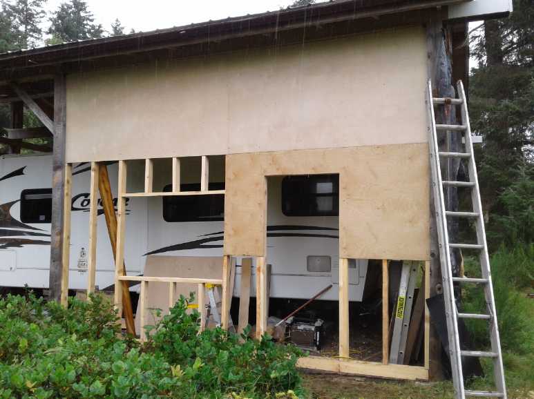 East half of the South wall of
the outbuilding
as of Sept. 1.
(Somebody noted "No cripples around the window?" But it's
post and beam, so even the outside walls aren't bearing walls.)
The 'model airplane' batteries for the model ground effect
vehicle arrived on the 4th. On the 11th I belatedly ordered "6S balance
chargers" for them. (Why have I been farting around with separate
chargers? Oh well. Why am I farting around with lithiums instead of
getting my own nickel-manganate-zinc cells going?)
CAT, HAT and "T-Plug" Connectors
In doing that I ran across something called "T-Plugs", or
"Deans Connectors". The batteries had a "T-Socket" as the main load
connector for however many zillion
amps to the propeller motor. They looked very similar to my own "HAT
36V"
connectors. In fact, a HAT plug actually fit into the T-socket on the
battery and the lamp worked.
It occurred to me that these ready-made, "dime-a-dozen"
connectors would be perfect for 'off-grid' wiring. I trust that they
would be fine for 15 or 20 amp circuits, 40 and even 60 amps being
mentioned for model aircraft use. Since 12 volts is by far the most
common, I decided to drop CAT 12V connectors in favor of them. Then I
would modify HAT 36V connectors so they wouldn't fit. But I might use
the T-plug pins in the new 36V design and just change the spacing by a
couple of millimeters.
It seems to me that it's a big advantage from a market
acceptance point of view to use existing suitable connectors, even if
they've only been used for model aircraft in the past. And while in
that application any voltages may be connected, their use in 12 volt
off grid wiring would soon so eclipse model use that they would come to
be viewed as "for 12 volts" connectors, and replace those silly
"cigarette lighter" connectors.
It's also a big advantage, at least for starting up
production, not to have to make the connection
blades. I will probably make nylon shells for safety anyway, as the
usual ones
they come with are cheap low temperature plastic. (Or perhaps I can
find some
better quality ones?) The blades push out of their shells easily enough
from the back.
Very few HAT plugs, sockets and wall
receptacles have ever been made. All that will be lost by modifying
them to not fit with T-plugs is a little design time.
So I ordered 50 pairs of the basic T-Plugs and
T-Sockets on the 11th, the same day I found them, and a few plugs with
wire-enclosing shells for appliance cords and extension cords.
Additional
"T-Plug-12V" components to be created:
* wall receptacle plates for fixed wiring (to hold, eg, duplex,
triplex (DONE!), fourplex T-Sockets)
* Plug shells that enclose the wires, for appliance cords
* "cigarette lighter" adapters with a T-Plug socket
* wire crimp-on and or screw-on T-plugs and T-sockets (consumer
alternatives to
soldering)
* outer shells incorporating strain reliefs for the wires for appliance
and extension cords
* click-lock outer shells for automotive and marine use.
If I get these done then it'll all be ready for general consumption. If
I can market them could they bring in actual revenue?
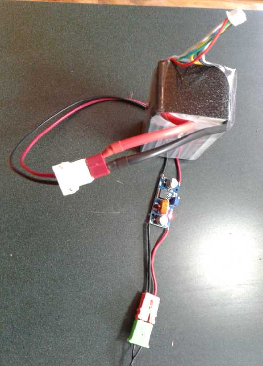 My white HAT plug plugged into
the battery's
red
T-Socket, powering the DC to DC buck
converter, which powered my 12 volt LED table lamp, which lit
the scene for the picture
The order arrived on the 31st and that very evening I
modified the triplex wall receptacle plates to take T-Plug sockets. I
got it very close and after tweaking, a second version was a great
working model. The sockets friction-fit tightly in their housings and
the plugs plugged in perfectly. I wired it up, and printed a couple
more of them without further modification.
[Sept. 3rd] It occurred to me that for 36 volt connectors all I needed
to do was change (widen) the pin spacing a couple of millimeters to
render them incompatible with the 12 volt type, and use the same plug
and socket pins. With this simplification I wouldn't have to design a
new spec, and variety of inventory would be reduced. Designing
receptacle plates and other surrounding paraphernalia would also be
quite simple changes to the 12 volt versions.
(T-Plugs are Covered in more detail under Other "Green" Electric
Equipment Projects.)
Low Voltage Shocks!?!
I've written that people don't usually get shocks (still
less, electrocutions) from under around 40 volts. It doesn't break down
skin resistance. In disconnecting some batteries in the Sprint car, I
got a mild shock from 24 volts. Then from 18 volts.
What had happened?
Both shocks were at the same place on the same thumb. I had been
working on the lathe and had had a tiny metal sliver there. I
had thought I had pulled it out with cuticle cutters (my favorite
sliver removing tool). It no longer hurt. But apparently I had merely
cut it off at the skin line, and it conducted electricity through my
skin resistance.
Winston/Thundersky Batteries: Tight strapping and Failures?
Quite a while back, I wrote that someone had given me a
couple of Winston/Thundersky 100 amp-hour lithium-iron-phosphate
batteries that
refused to charge above about 3.29 volts. Usually when charged the
voltage will rise to whatever is supplied (max 4.2 volts). These just
kept drawing current, without the voltage rising further. I found more
and more that did it after I had taken the same type of batteries out
of the
Suzuki Swift EV.
I wrote of getting some new 120 amp-hour 3.7 volt lithium
cells this month. The problem for selling them as solar components was
that the most common voltage is 12 volts, and they aren't close enough:
three makes 11.1 volts (various 12 volt equipment items will balk at
that), and four makes 14.8 volts. If those are being charged the
voltage would be even higher and would risk "frying" 12 volt
appliances. So I decided to use the new cells in 36 volt configurations
(3.7*10=37V - pretty close) and I could sell the used 3.2V
(3.2*4=12.8V) batteries instead.
And as it happened, in August someone wanted a 12 volt
solar panel system. I pulled another battery out of the Sprint. But it
wasn't well balanced, with two of the four cells refusing to rise above
3.29 volts. I checked the car and found a well balanced one. It was one
I had taken the aluminum end plates and stainless steel strapping off
of to change the layout (to reverse "+" and "-").
I went to put the end plates and straps back on. They were
too tight and wouldn't go on. I brushed them off to make sure there was
nothing holding the cells apart a little. I thought "This should have
been a 5 minute job. Aren't these the same cells the strapping came off
of?"
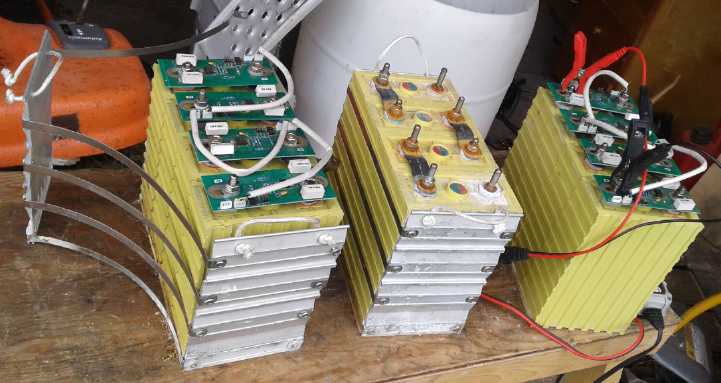 Then I had another thought.
Originally the straps had fit.
Now they were too tight. The straps couldn't have changed, so it must
be that the battery cells had swelled just a little. Furthermore... none
of
the
cells
that
weren't
bound
tightly with straps had the problem.
And
a battery I'd been given that wouldn't rise above 3.29 originally
had worked fine when I tested it about a year later. It seemed the
cells were having trouble when they were jammed in and couldn't
swell up, just a very little bit. If they had just a bit of room,
they
didn't have a problem. And one I'd been given had even seemed to "fix
itself"
after being left loose for a while.
The seemingly growing
number of cells in the Sprint (some
of them now in the Miles truck) that had been misbehaving were making
me
uneasy. I took all the strapping off all of them. It was less
convenient for carrying them, but it maybe they would stop "going
rogue", and perhaps some more might even "get better" again.
The 60 amp-hour batteries had similar straps on them. On
one set one of the extruded aluminum end plates was actually bulged
out, bent, indicating considerable pressure on the cells to expand.
When I undid the screws, the strapping sprang off. (There were a couple
too few good ones of these to use them for 36 volts or I would have
been employing them. Unless I use them for 12 or 24 volts for
something, they don't seem to have much purpose.)
The New Lithium-Ion 3.7V Batteries
These needed just 10 cells for 120 amp-hours, 36 volts
(actually 37V). Ten of them in a cardboard box weighed just 44 pounds.
Thirty of them would provide the Sprint car (should I ever get it going
- anyway it's my house/solar battery backup power) with 360 amps-hours
at 37 volts: 13,320 watt-hours for just 150 pounds weight.
With the old ones it was 36 cells giving ~38 volts and 300
amp-hours: 11,400 watt-hours for 270 pounds weight.
To get 12 volts for the car lights and all, instead of
another battery I would simply use a DC to DC down converter. That will
also provide an even drain on the whole 36 volts, instead of the
previous setup which ran the lights off the lowest 12 volts of the 36.
Culvert Hydro?
I'll preface this theoretical topic by saying that the
only way I
would undertake such a project would be (a) if the regular power was
down with no reasonable prospect of it coming back on line any time
soon, (b) with permission (or in the absence of anyone to say "no"),
and
(c) if the local neighborhood was solidly behind it to the point that
they would volunteer to do most of the work. I would supply the overall
plan, the improved Piggott alternator and probably a few mechanical
parts.
These conditions might be met if things were bad enough
for long enough. Here the power would likely go off, or be off for
extended intermittent periods, if supplies of diesel fuel were cut off.
(The small hydro plant can only run when sufficient rains have kept the
lake full, and now it may not be enough to supply everywhere at once
anyway.) As times are getting rather chaotic for the coming decades,
such contingencies may be thought of. But then again they may never
occur.
I went for a walk, and I decided to look at Lawn Creek,
thinking, what sort of hydro project might work on it? There were many
drops of a few inches, maybe even a foot. But not close together and no
real waterfall. Those might be amenable to some sort of undershot wheel
with
its own "scoop" base to direct the flow across the blades. But to get
very much, one would either need a dam or else a very long pipe to
bring water from higher up to a lower place.
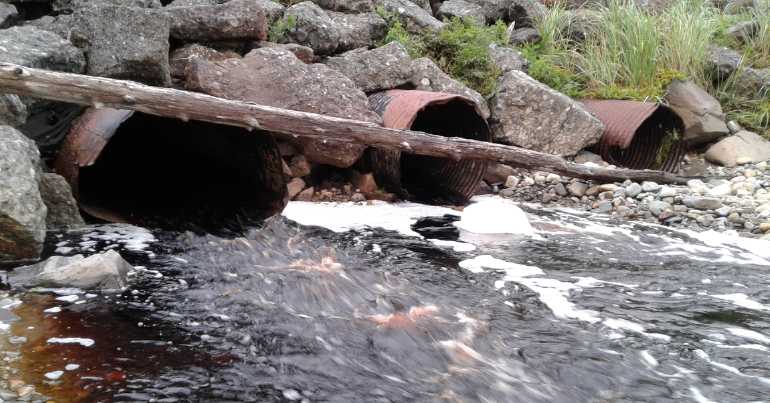
Then I thought of the culvert where the creek went under
the highway. It was three 6-foot diameter metal culvert pipes. Most of
the time the water just ran along the bottom of two of them and didn't
reach the third one, a foot or so higher up. In heavy and constant
winter rain storms, it probably filled the two lower pipes and came
part way
up the third.

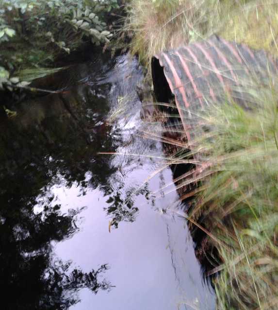 If one blocked the entries to the pipes, the water would
rise up and flood a very small area. So the highway would be an instant
dam. One might block, say, the
bottom 5/8 of the lowest pipe, 1/2 the next one and 1/4 of the third,
perhaps with plywood.
Then the water would build up to the 1/2 closed and 1/4 closed pipe and
start spilling over into those culverts, but not quite to the top of
the 5/8 blocked. That one would have a nozzle spraying on a pelton
wheel just inside. The shaft would come out and up so that the
(improved Piggott) alternator was above the culvert pipe. It would be
attached to the wooden cover, as would the bearing for the pelton
wheel. I think that would give sufficient power for LED lights and
fridges in a few nearby houses. It would be consistent power as any
excess
water would just spill over the other gates. (The other two, at least,
would probably have to be removable for heavy rains to prevent flooding
the highway.)
Since the highway runs up and down the coast there would
be a number of culverts that might be suitable for this simple sort of
"neighborhood micro hydro" system.
I speculate that 208/240 volts AC would be the desired
output - assuming one can derive 120 from it. (Else 120/139. It's a 3
phase alternator, so those are the choices.) Running lower voltages
along roads even to nearby houses
would entail heavy losses. Pelton wheel diameter (and hence speed) and
the number of winds of wire in
the stator windings would determine the voltage and frequency.
A later thought was that a box with the pelton wheel
should be on the outside of the plywood covering the culvert pipe (but
with an open side spilling out to the inside), with
the generator shaft going straight up to the generator box above.
Nothing would be inside the culvert pipe. That should simplify
everything.
In Passing
(Miscellaneous topics, editorial comments & opinionated rants)
Cure
for & Prevention of COVID19
With all the hype, societal
distress and economic disruption over COVID19, which is for sure an
insidious and dangerous disease, it is quite a surprise that finding an
effective treatment and preventative for it in the spring wasn't all
over the news in
May or June, or at least by July.
It is perhaps a sign of how dysfunctional western society has become
that while the lab tests were done in Australia in March, and patients
were treated in a hospital in Florida in April, it is being adopted in
places like Peru, Bangladesh,
Dominican Republic and Brazil rather than in Canada, USA, EU and
Australia. Instead we're still enduring dictatorial lockdowns,
isolations, "social
distancing", face masks, hand sanitizers whenever we go into public
places, and immense overall economic turmoil - all apparently
needlessly.
"Big Pharma" wants to develop a costly new vaccine (a
company trying has already said they would charge a fortune for it).
Simple pills of an existing, low cost and well known medication with
few side effects simply aren't what anybody expected - or 'big pharma'
wanted to see.
Nevertheless
that's just what has been found. It's had no publicity in the
corrupt "mainstream" media while people everywhere continue to suffer
and a few die of the virus - now, it would seem, needlessly. (But
perhaps doctors are using it quietly - a recent chart shows the number
of deaths from CV19 dropping off dramatically.)
The medication is called Ivermectin (AKA "Stromectol"). It
is almost 40 years old. It was developed to cure people of parasites
such as nematodes and worms. It was also known to be effective against
certain viruses. It was a surprise that it
seems
remarkably effective against the COVID19 virus. Improvement
even in very ill patients is evident within 48 hours, and they test
negative for the virus within 10 days. It's not perfect, but it can be
used at any stage of the disease, from prevention to even to severe and
critical - where it cuts mortality roughly in half.
!!! [Inserted at time of posting] Warning: Doctor
Mobeen Syed (DrBeen.com - youtube video titled "Ivermectin Remdesivir
Leronlimab") warns that ivermectin should not be used by pregnant or
lactating women (it crosses the placenta and might cause brain damage
to the fetus or baby), nor by meningitis patients or anyone else whose
blood/brain barrier is compromised.
Orthodox medical journals are viewing it cautiously or
skeptically to say the least. Doctors treating patients, however, are
enthusiastic. It has been spread among doctors' social media groups,
and there are a number of interviews with doctors at the forefront of
it on youtube. (This shows the value of social media, morally polluted
as it may be on certain topics. How else would the knowledge have
spread
"virally" between doctors?)
The first and at the time unknowing or "accidental" use
seems to have been in a Toronto nursing home where there was an
outbreak of scabies in February (2020). Owing to that, the residents
were all given Ivermectin.
In the next couple of months CV19 was killing the elderly
in nursing homes in droves. Not at this one! Many staff came down with
it, but very few residents. This was a great effective blind study.
https://www.youtube.com/watch?v=8XCYzpHBEkI
Then in March was the lab study in Australia.
Perhaps the first doctor to knowingly try it on a patient
was Dr. Rajter in
Broward county, Florida. He had just read of the Australian test tube
study a couple of days previously. He had to phone the son of a patient
who was getting worse and seemed likely to die. The man asked, wasn't
there anything that could be done for his mother? Finally the doctor
hesitantly mentioned the study, but said he
didn't know the dose used or how much was safe for humans. The son
asked how
much was used for the treatment of parasites, and the doctor told him.
Why not try that amount, known to be safe, then, asked the son? The
doctor and the patient agreed, it was done and she recovered. Some of
the doctors in the four hospitals of Broward county went on to treat
other serious cases with ivermectin, cutting the mortality roughly in
half in several hundred patients. Especially at first, Dr. Rajter could
hardly publish the findings as a "study",
but he posted to a doctors' social media group, and soon ivermectin was
being used in many countries.
https://www.youtube.com/watch?v=nzqnAIfEbv4&t=618s
The presenter of the video notes that in spite of the
"carefully controlled off-label observational study" which was approved
by Broward County, a major US county health board, no medical peer
review journal seems willing to publish it. The mainstream media, for
all its hype about CV19, seems equally uninterested in hearing of what
appears to be a cure.
Dr. Pete Ellis, "at the epicenter" of the infections in
Brazil, has been treating patients with ivermectin with great results
and also taking it himself as a preventative. Here is his excellent
video, in which there is much information including suggested dosages:
https://www.youtube.com/watch?v=9gApbQlSIAA
(Dr. Ellis is 78? years old and was in intimate contact with people who
were catching or who had the virus including family members - a prime
candidate for catching it
and dying from it. If I was an elderly doctor treating CV19 patients I
would surely take it, too!)
Here' an Ivermectin Study that claims 100% success curing
CV19 in 6 days. Other clinical trials in other countries, shortened
CV19 from 20 to 10 days.
https://www.youtube.com/watch?v=VfTvViI8IKI
Of course I am not a medical professional. I am just
reporting something I've found that seems very interesting and
relevant. I'm sure results of any treatment will vary with every case.
Some people test positive for the virus without having any symptoms.
Only a few percent of cases (4%?) result in death.
And there may be something more effective, too.
Remdesivir, touted by many professionals, also seems to help
significantly shorten the disease's stay. Is it better?
Lest we rejoice too much over cures for CoViD-19, it seems
a new (or not new?)
virus initially spread by ticks has been claiming victims in China.
(Only a few so far.)
https://www.youtube.com/watch?v=llpv1BNhoGg
A school bus driver here said he thought Haida Gwaii had
already had CoVid-19, because in February a lot of people were quite
ill. That was of course just before it was hitting the news.
That reminded me... I flew to Comox BC to see my own
mother for Christmas 2019. CoViD-19 was not yet known. In a 6 hour
stopover at YVR on the way there, I seem to have caught something that
made me quite ill for a few days after New Years day. (Looking back, I
described it as "a nasty chest cold" in TE News #140, for which I had
put steam on in my bedroom.) And my 94 year old mother caught it in
early January, probably from me. (She was needlessly sent to hospital
by ambulance by a concerned friend in her building. She said she would
have gladly gone to hospital the day before, but had been feeling a
little better by that day and after seeing a doctor, went home (by taxi
I presume).)
Perhaps what we had was CoViD, and perhaps more people on
this island caught it in January and February from me and other
Christmas travelers? Then with our low population density here and and
the later containment measures, by the time there were tests for it, it
had disappeared.
That is of course idle speculation. As far as I know, no
one died from whatever it was. And the later 26 cases stemming from a
Haida man who went to the USA by car to pick up his daughter, and then
they both went to a funeral immediately on return, didn't spread any
further and it died out - perhaps again.
Wall
Building
Here are some pictures
showing the progress on making the wall.
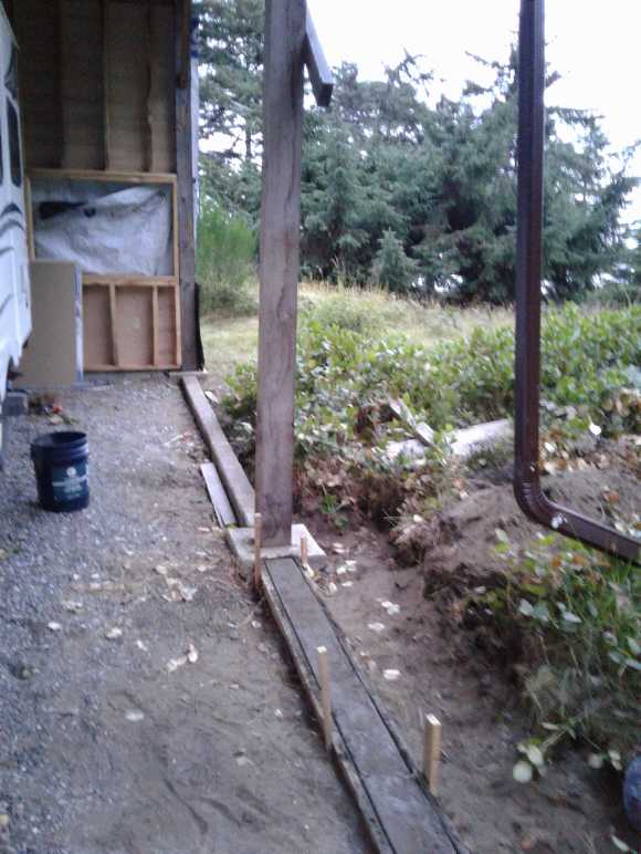 Thin concrete footing walls. The
posts
(on concrete footing blocks) and beams
support the roof, so no wall is a bearing wall. So the main objective is that the
wood of the
walls not be in contact with the ground. (With the rising ground,
I'm
going to have to
dig some more dirt away from near the walls.)
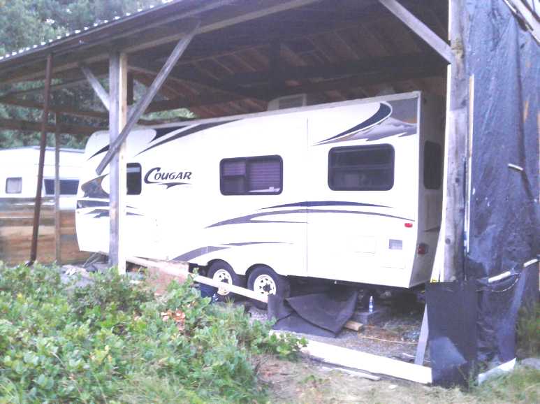 2x4 frame around the outside.
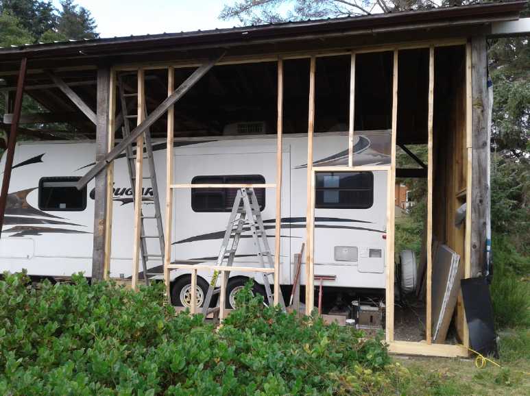 Wall Partly framed with 2x4s.
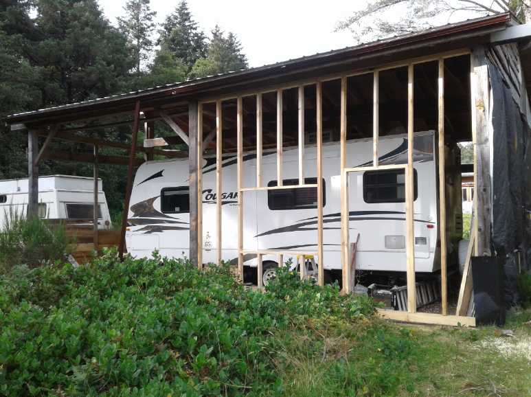 Framing Done. The window frame is
a bit
unorthodox.
It must be remembered that with the post and
beam construction, no walls are bearing walls.
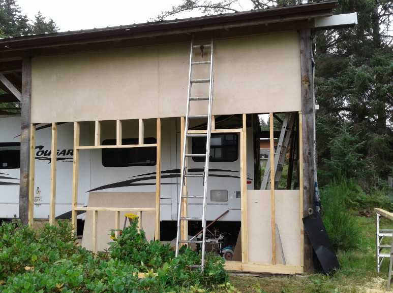 First two sheets of plywood.
 With 15-1/2 feet of length, the
only place to
put the plywood joins is
"all at the same stud". (Except at the bottom row.)
(Drizzle wetted the sheet as I cut it, temporarily changing the color.)
Telling
Fake
News
from
Real
News?
I think I've found a good
indicator of
"fake" versus "real" news on Youtube. When the comments are turned off
by the video producer, it's a good indication that the video is pushing
a narrative -- or at least that they don't want other views or opinions
on the
subject to be aired under their video.
I found a CBC video, The controversial push to
fast-track a COVID-19
vaccine. I thought I would look at it, mostly to see what people
were saying underneath. And if no one (or the video itself) had
mentioned ivermectin (AKA "Stromectal") -- the low
cost, "at hand", apparently safe and effective, oral treatment (and
even preventative) that is getting no publicity while "they" have
everyone vainly hoping for an injectable vaccine, I was going to do so
myself.
And I might find other unsuspected, enlightening facts or ideas
that people had posted.
The comments were turned off. I was disgusted and didn't
watch very
much of it. As far as I did watch there was some hype for vaccines in
general (yes, yes, there's no question but that smallpox vaccine
virtually eliminated that horrendous disease), and no indication they
would mention
any possibility for treatment but the "holy grail" CV19 vaccine (which
may still be many years away) -- a
very narrow focus and perspective, certainly not the "big picture".
What are you scared of, CBC? Truth? (Note: Not all CBC
videos have the comments turned off.)
Gardening &
Chickens
In all the following gardening writeup, it must be
remembered that summer
2020, and especially August, had very little sun. Where the solar
panels had made 307 KWH in 2019 - which itself wasn't a very nice
summer - they only made 205 KWH in August this year. Perhaps it's
surprising there was much of anything besides potatoes.
Wheat Growing Experiment
This spring I ordered small packets of 5 different
varieties of wheat, "ancient grains?" from Saltspring Seeds. I wanted
to try wheat growing
in general, and I wanted to see what grew well on these islands. On the
14th I plucked a few heads. It had been raining for a couple of days
and was pretty cool, not to say cold for "summer".
 First thing of
note from the main garden was that much of
the Red Fife had fallen over in the rain. Much of the Kamut was
bent over randomly, but not fallen.
The second thing was that
the wheat in the garden by the
south side of the house, in spite of having a head start by virtue of
being planted indoors in flats earlier in the spring and then
transplanted, didn't fare as well as that simply planted outdoors in
the open field a
little later. That side garden just didn't get as much sun, and most of
the wheat there was drooping over by the 14th. (The more so as some
Elderberry bushes grew up rapidly over the summer next to the wheat and
cast a lot of shade. They were cut back on the 11th FWIW.) So we'll
make allowances for the smaller side-garden heads. Since I grew Kamut
in both locations, it makes for some comparison.
The Alaska Spelt grew the tallest of the ones in the
side-garden, and seemed to stand up best to the rain, but it seemed to
have the smallest kernels and obviously it was difficult to get them
out of their chaff - the seeds right from Saltspring Seeds were still
in the chaff, whereas all the other varieties were just bare kernels. I
won't plant them again just because they are harder to process. Emmer
is apparently similar.
The Emmer grew next best to the Spelt (and was next to
it), and was riper than any others in mid August, with the sheaves
starting to turn brown. For that reason it might be worth further
trials, especially if the others aren't ready by, say, mid September.
The Kamut next to the Emmer didn't grow as well as that in
the open field. It still did not bad and still had the biggest kernels.
The Brazilian Lavras didn't grow very well, but it was the
most shaded by the Elderberry bushes, so it might not have had a very
fair trial. Still the fairly similar Emmer had bigger and more golden
heads, so I think I'd go with the Emmer over the Lavras. But I don't
expect I'd grow either again.
The Red Fife from the main field had formed good heads
with good green kernels inside, but it had fallen over. We get a lot of
rain and cool cloudy days here, and it didn't fare as well as the Kamut.
I'll drop the Spelt and Emmer. I might
give Red Fife another chance, and perhaps a small patch of Brazilian
Lavras, which didn't get much of a chance in the shade of the
Elderberries. But the Kamut was looking like much the best
choice.
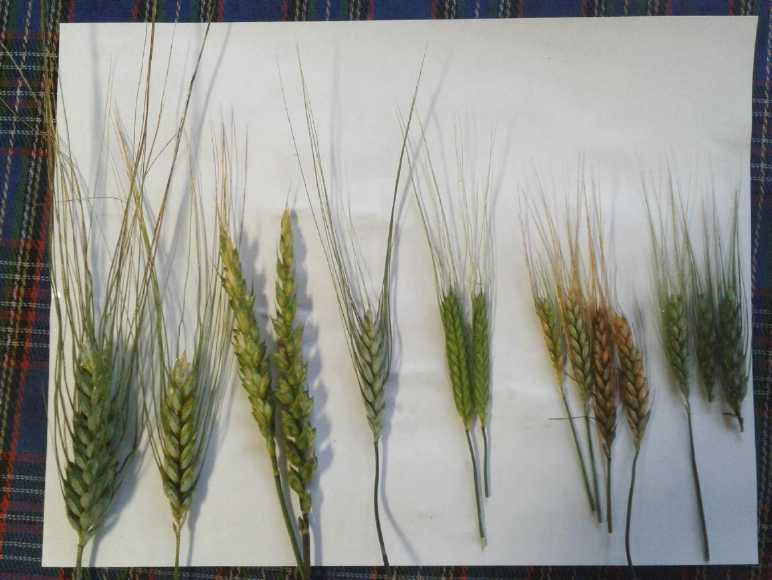 From left to
right:
* Kamut (Chorazin) and Red
Fife (from the larger sunny garden, planted
direct later)
* Kamut, Alaska Spelt, Emmer,
and Brazilian Lavras (planted in flats
early and transplanted to the side garden)
But the heads of wheat weren't at all mature yet. The
husks had developed, but the kernels inside were still tiny and
unformed.
(24th) I checked on the wheat again this day. Some of the kernels were
much better formed but were still soft and green. One could at this
point open individual kernels and eat them like green peas, but it
wouldn't be worth the effort. The most developed ones were again the
Red Fife and the earliest planted Kamut in the big garden.
The Emmer, for all the early golden color, was
disappointing as was the Brazillian Lavras. The Alaska Spelt were still
pretty small - and why bother with it when they seem so hard to
de-husk? Admittedly these three varieties weren't grown in the best
conditions, but they still didn't match the Kamut in the same patch,
planted about the same time.
On September 3rd I checked the earliest planted Kamut and
Red Fife in the field again. The kernels were probably about full size
now, but still green and "chewy" soft.
The outstanding performer seemed to be the
Kamut in the open field. Most of it was still upright. The kernels were
developing well in spite of the cool, cloudy, wet weather. Remote Haida
Gwaii will never be a breadbasket of wheat, but if growing an acre or
two here and there of wheat for local consumption should seem like a
good
idea, Kamut would seem to be the choice. Red Fife comes in second. It
too had decent size kernels ripening, and had bent up again after
pretty much falling over in heavy rain.
Peas
 Peas are one of my favorite garden vegetables. Of three times and
places I planted peas this year, the largest one did great!
Home grown
peas are delicious -- much better than frozen store-bought peas. The
store-bought ones are blanched in case anything has started growing on
them. I shell peas and immediately freeze them - I figure they're fine
that way and taste much better, retaining more nutritional value, and I
have never got sick from them yet (AFAIK).
With the new larger garden space, this year I planted a 4
meter row of "tall telephone pole" peas. (with a narrow gap for a path
through the middle.) It produced well even through cool, cloudy August.
On the 25th after leaving them perhaps a week, I picked, shelled and
added another 300 grams to the freezer bag, for a total of 900 grams of
frozen peas. It all took maybe half an hour. I had used a few and there
were still plenty left, so it must have yielded over a kilogram.

 By the end of
the month I had harvested a Kg of
peas and
put them in the freezer, not counting what I had eaten plus some to
plant next year. And there were still some more ripening on the plants.
I picked some of that on September 3rd, putting another 95g of what
I'll call "late season peas" (less tender and sweet) in the freezer and
drying almost as many for next year's seed.
Inevitably one misses some until the plants have died and
dried up, but that's good as the old dry peas become more next year's
seeds.
(If there are more than needed, one can store them dried anyway, and
use them in soups. With solar panels et al, I'm counting on being able
to keep
the freezer going regardless of anything.)
Other Vegetables
I grew quinoa again, but it didn't seem to do very well.
Something was eating holes all through the leaves. Three red colored
plants started to flower early and then died. The tops were eaten off.
A deer had got in and I attributed it to that. But in late August
flower
tops on the other plants started to turn red, and then they too were
being eaten off.
I'd seen a couple of birds fly up from the garden when I
came out, little brown wrens or something, but they were down on the
ground, not up at the flowering
tips. Then I figured it out: they pecked off large chunks of the tops,
which fell to the ground. Then they spent most of their time on the
ground eating them down there. At least, that's my surmise.
 Swiss Chard and Zucchini -
planted to replace
young quinoa that the slugs ate.
Behind them, a whole bare patch where carrots were replanted at least
twice
but eventually grew only a single good carrot. Why did they not come up?
Why did they all gradually disappear when they did come up, instead of
growing?

Garden by the south wall of the house, with the corn that was under
cover during
the spring and actually had edible (but not large) cobs, and some bushy
quinoa behind
it before the birds (? - or mice) got to it.
 First two cobs. Many were a
little better, but
none were full.
 Birds (at least I think it was
birds)
decapitated the quinoa and
left it in ruins as the flowers started to turn red.
Very disappointing! (This was September 1st. It got worse until whole
plants
were dying or dead. No crop - including from those in the greenhouse.)
 Soon after, they got this one,
too.
 Onions by house were okay, not
spectacular but
as well as I've ever done with onions.
Garlic from same place seemed good, if a bit small. More peas and some
wheat.
The corn I planted indoors and then put under plastic by
the house grew and matured. When I picked the cobs they were
disappointing. One cob had just 20 kernels on it. A couple of others
were about half full. This indicates poor pollination, notwithstanding
that I had taken some tassels and shaken them onto the silks. A bigger
patch would obviously be much better if it can be protected from the
weather until it's growing tall. Nevertheless, it's the first edible
corn I've grown up here and it tasted great!
The cover plastic over the other corn out in the new
garden had ripped early and in several places, and I didn't get around
to replacing it until late. It never matured, having cobs just starting
at the end
of August.
The Chickens
 The chickens on August first (and
some
freeloading deer).
The only trouble was... four out of five were roosters.
I had already culled one rooster, still at least two more had to go.
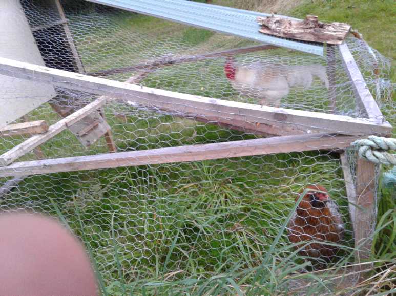 The survivors. (The hen started
laying small
greenish eggs in mid September.)
I did the 'lesser' white one early in the month. On the 16th my friend
Perry killed the boisterous (not to say cocky) big
black rooster for me. (It's not my favorite sport.) I had meant to take
a picture of the three, but
when I thought of it it was too dark, and I didn't think of it again
until he was gone. With the lesser white one having been consumed early
in the month, it's down from 4 roosters to one off-white leghorn, and
the hen with the fluffy cheek feathers.
The chicken feed consumption has dropped dramatically. I'm
not sure they get a whole lot from foraging at wherever I move the
chickenmobile to, but ferns, garden weeds and trimmings, and food
scraps, stretch out the supply. (If chickens liked slugs, it would be
great! But to eradicate slugs one evidently needs ducks, who think
they're a delicacy. Evidently they are not only gross but poisonous to
humans.)
The 3 roasters tasted great, but I'd rather have had at
least two hens. Egg supply was what the project was about! And my
timing was poor: they're 4 months old now, another month or two until
she starts laying, and the days are quickly getting shorter. Chickens
lay by the light - when the days are long. Better to have got chicks in
the fall to start laying in the spring. Or maybe I should put an LED
light in the coop on a timer. Any light works.
Small
Thots
* Some have been calling birds "avian
dinosaurs". Obviously they evolved from dinosaurs, but that would seem
to be stretching the point considerably. So did placental mammals. Does
that make mammals "non avian
dinosaurs"? (Bats excepted of course.) Kangaroos even look like
dinosaurs. Then, reptiles evolved from
amphibians. Does that make dinosaurs "non avian frogs"? And are frogs
"extra-aqueous fish"? Does that make birds "avian fish"?
 * Here is a
graph projecting future populations. These are mostly going the right
direction, but it's too little, too late to prevent upcoming
catastrophes.
I have the impression our food supply chain is thinning
out and will soon be largely empty, inaugurating a great population
reduction by hunger and poor nutrition. On top of economic and
financial disintegration, the flooding in China this year has been just
as staggering as that of the heartland of the USA last year. Now we
have locusts decimating various regions, droughts, winds, hail, cold,
CoViD-19 shutdowns... and fires ravaging the western USA, especially
California where so much of our food is grown.
Still, it's a good sign that population growth is slowing
so much before people are hurting. When things settle down, and birth
control products are available everywhere, it looks like the world
should have little trouble keeping a stable population at a size where
in future generations everyone can have a prosperous and fulfilling
life and grow into their full potential. (under 3 billion, perhaps?) No
more marginalized, homeless and economic refugees searching for
anywhere they can settle and make ends meet, contrasting with the
outrageous wealth of a few, and everyone in fear of and in competition
with everyone else for what limited resources there are.
ESD
(Eccentric Silliness Department)
* Quiz: Do dinosaurs have gizzards? (Rest assured there are no answers
known to be entirely wrong. Except maybe "(e)".)
a) Probably
b) Unlikely
c) Maybe some did
d) Who cares, dinosaurs are extinct
e) None of the above
* I think Brazil is the only country named after a nut. Except for
countries named after certain people...
Chemical Elements Spotlight
Sb: Antipathy is next to Te and also to Sn, sandwiched between As and
Bi
in column 15 of the periodic table (N, P, As, Sb, Bi). It doesn't like
any of them.
P: Prosperous is near the top of the same column. There's plenty of it.
Te: Delirium is the last element found sleeping in column 16: O, S, Se,
Te, Po. (Po never sleeps, being highly radioactive and also a river in
northern Italy. O2 is always active, too.)
"in depth reports" for
each project are below. I hope they may be useful to anyone who wants
to get into a similar project, to glean ideas for how something
might be done, as well as things that might have been tried, or just
thought
of and not tried... and even of how not to do something - why
it didn't
work or proved impractical. Sometimes they set out inventive thoughts
almost as they occur - and are the actual organization and elaboration
in writing of those thoughts. They are thus partly a diary and are not
extensively proof-read for literary perfection, consistency,
completeness and elimination of duplications before
publication. I hope they add to the body of wisdom for other
researchers and developers to help them find more productive paths and
avoid potential pitfalls and dead ends.
Electric
Transport
Miles Electric Truck: New Planetary Gearbox
Around the 20th to 23rd, I put the planetary gear end of the shaft in
my lathe. It wobbled as it turned. How on Earth was I going to make a
"steady" for it? I idly tried to mill a little... and it centered
itself! What happened was that the one inch shaft pressed itself into
the one inch hole in the 3-jaw chuck, and that centered it perfectly. I
still had a hard time. It was very hard metal, and I actually spent
several hours of trying to sharpen lathe tools/bits and cutting the
25mm down to 19.0mm. (For some reason the last millimeter seemed easier
than all the rest.) I had to take the chuck off the lathe and hammer
the shaft out of it.
I then pressed it into the other end of the shaft coupler
with about 4 tons of force. I don't think this shaft will come apart
without a lot of persuasion. Next, to put it into the truck, which
wasn't up on ramps and couldn't be driven onto them until the shaft was
in!
 Two shafts pressed into shaft
coupler to get
the two proper ends for
splined motor socket and 19mm compression socket on planetary gear.
[28th] I finally went under the truck and dismounted the old shaft. I
took the planetary gear with the rear drive shaft right off the truck,
as there was no easier way to fit the assembly together. The planetary
gear end of the new shaft was just marginally too big to fit into the
socket. I tried to pound that end of the shaft out of the shaft coupler
with a big vise and a hammer. It wouldn't budge. Then I tried putting
it in the lathe, gripped from the very end of the join and with the
motor end in the drill chuck at the other end of the lathe to hold it
steady. Contrary to my expectations, the shaft wasn't straight.
Nevertheless I took a file and started filing it down until it was all
under 19mm diameter. I hope the wobble wouldn't be noticable on the
truck.
It still wouldn't go in, so I just filed it down a bit
more until it did, and worked it in. Then I pushed the front into the
motor and put it all back together.
One of the lithium batteries had a cell that was dying
before all the rest, and I took it out. I sold the best 8 cells for
Steve's solar project, making two 100 amp-hour, 12 volt batteries.
There seemed to be a lot of misbehaving cells left over (see under Electricity
Storage). I would have to pick 4 cells to put back into the truck
before I could drive it.
Other bad news was that Randy of Canadian Electric
Vehicles (retired) said he had never run across a Curtis motor
controller that wouldn't 'talk' properly to the programmer. He did
suggest I contact "HPEV", who he thought had done the components for
the Miles EVs.
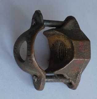 [29th] I put
in another lithium battery (misbehaving or not), and then
ran the truck around the driveway. Contrary to my hopes, the vibration
from the unbalanced shaft was pronounced with even a little speed. I
put the truck away, exasperated with the whole thing. Why had
I started this? Then I thought, with unbalanced tires they add
counterweights until they are balanced. Why couldn't I do that with the
shaft? And I had found a strange clamp that went on a pipe, and had
thrown it in a box just days before. It might be just right, or at
least it was the right idea. I dug it out again.
But that might not be a
satisfactory fix. The planetary
gear, if not the motor, would wobble back and forth a bit and might
still make for a lot of vibration. It occurred to me
that even tho I hadn't been able to budge the shaft from the coupler
with hammer and vise, if I stuck it in the hydraulic press sideways and
pressed down on the shaft coupler with the two ends supported, it would
doubtless "bend". That is, one shaft would pull loose a bit on one side
to straighten it. And I could test the straightness the same way,
putting
it in the lathe with both ends supported, and turning it to see any
wobble. (Repeat until it seemed good.)
Ground
Effect
Vehicle
(1/4
scale
model)
(11th) On discovering the main output wires of the batteries went to
"T-Plug" sockets, and that those would make a very good replacement for
my own HAT (or CAT) plugs and sockets, I ordered a bunch of those. Now
I have the excuse that I'm waiting for the plugs to arrive before
continuing on the model. (The real excuse is as usual, I'm too busy. I
even bought 2 cords of firewood for this winter because I simply
haven't got around to cutting any myself all summer.)
I'm also suspecting that it may need a tail rudder. When
the fans were to be on the outside of the hulls, they would have a lot
of turning force. Now that they are inside on the canard, that force
will be considerably less. Even with one off and the other on high the
turning radius may be very wide. OTOH the 'shark fin' pivot point being
well forward may make for sharper turns with less leverage than might
be expected. I guess I'll find out when I fly it.
One thing I think I might do immediately is make an
electronic circuit to (a) reverse the 'backward' throttle controls so
they shut off if the radio control signal is lost instead of turning on
full, and (b) so that pushing forward on the stick increases the
throttle and moving it side to side turns one engine up and the other
down for turns.
(Let's see... a 5 volt rail-to-rail dual OP-AMP... How
about a CA3260? - the same one I used in my last OP-AMP circuit design
in [egads!] 1986?)
Defining just what was wanted was a bit of a trick. With
two independent throttle sticks (as I intend on any full size craft,
including pulling back past 'zero' for reverse thrust for maneuvering
when docking) it would have been easy. Having just one stick that moved
four directions (and no reverse in the "ESC" motor controllers) was
different, and all radio controls for model aircraft seemed to be
configured the same.
1. Moving the stick from bottom to top (centered left to right)
obviously should take both
motors from fully OFF to full power.
2. Moving it left to right at the bottom should do nothing - both
motors should stay off.
3. Moving it left to right while at the top should decrease the power
of the one in the
direction of the stick motion. But by how much? Should it
turn it right OFF at the ends
of motion (cutting the total thrust in half), or
only partly?
4. What should it do in the middle of top to bottom, when moved left or
right? Still
decrease the one for sure - perhaps to OFF at the
extremities. But what should the
other one do? Should it increase (keeping the total
thrust even), or just stay the same?
The practical circuit is probably going to define some of
that. The motors can't go beyond full throttle no matter what the
control tries to do. So probably the thing to do is define what happens
going left to right in the mid throttle range. Surely it's best if the
overall thrust remains the same regardless of left-right position, so
the thrust of one motor should rise as the other goes down.
So I guess the thing is to define what voltages are
optimally wanted to the motor controls for the two motors at what stick
positions.
|
LEFT
|
MID
LEFT
|
CENTER
|
MID
RIGHT
|
RIGHT
|
TOP
|
5 - 0
|
2.5 - 0
|
0 - 0
|
0 - 2.5
|
0 - 5
|
MIDDLE
|
5 - 0
|
3.75-1.25
|
2.5 - 2.5
|
1.25-3.75
|
0 - 5
|
BOTTOM
|
5 - 5
|
5 - 5
|
5 - 5
|
5 - 5
|
5 - 5
|
So... Left motor off (off=5V) at the bottom OR stick is all the way to
the left; Right motor off at the bottom OR stick to the right.
And... if above OFF, the thrust inreases one way (left or right) and
decreases the other, hopefully to attain the MIDDLE row figures, and
also the BOTTOM row OFF condition must be met for both motors. What
happens at the TOP row in order to attain everything else is in the lap
of the gods.
So the function needed is a sort of multiply, vertical * opposite
horizontal, and then invert so off is 5V and full is 0V.
I wonder if perhaps the whole thing might be easier to do with a
microcontroller? (They most always have analog inputs... do mine have
analog outputs?)
How is it that ALL the 'green energy' and electric
transport projects seem to have got to be "on hold"?
Other
"Green" Electric Equipment Projects
New
System:
"T-Plug"
12VDC
--> Now Replacing CAT 12VDC <--
CAT, HAT and "T-Plug" Connectors
The 'model airplane' batteries for the model ground effect
vehicle arrived on the 4th. Being still busy, I set them aside. I
should have ordered "6S balance chargers" for them.
On the 11th I started looking into that on AliExpress, and
ran across something called "T-Plugs", also called "Deans
Connectors". (Apparently "Deans" was the first person or company to
make them,
although there are now other knock-offs.) The "T-Socket" was what was
on
the batteries as the main load connector for however many zillion
amps to the propeller motor. The connections all seem to be gold
plated. One place said they were rated for 40 amps. That seems pretty
optimistic. (Maybe I should double up the connectors?) I trust that
means they would be fine for 15 or 20 amp circuits. The wires from
these batteries were #10 AWG, which in house wiring is only rated for
something like 30 amps. But then they're only 5 inches long.
One minor oddity is that the 'springy' bit that presses
the blade into good contact with the socket is on the plug blade
instead of inside the socket. But that is perhaps an advantage. One is
needed somewhere. It means that the plug on the appliance cord is the
component to wear out and fit loosely instead of the socket in the
wall. And being exposed on the plug blades, one might perhaps pry them
out a bit to restore good connections.
Another oddity is that they are not quite
symmetrical, because the in-line negative metal is on one side in the
plug and on the other in the socket. Instead the contact plane
(the
socket having its contact blade only on one side of the plug blade
instead
of both sides) is centered.
There were also "XT30", "XT60" and "XT90" plugs for model
aircraft, with round pins. An exact matching unsymmetric shape of the
shell on both plug and socket is required to ensure correct polarity. I
decided that while I might make use of these as specialty connectors,
neither round pins nor the exact shell necessity fit my philosophy of
connectors for general RV/Marine/Off Grid house wiring purposes.
 The T-Plugs were another matter. The top of the "T" cross
was, like on my connectors, the positive terminal, and the in line one
the negative. Noticing the similarity in form and size, I got out one
of my 36 volt "HAT" connector plugs and tried it. The sizes were so
close that it plugged in, and the lamp worked! That made for several
choices:
1. Ignore T-Plugs and continue working on the CAT and HAT plug and
receptacle systems.
2. Adopt T-Plugs in place of HAT for 36 volt systems.
3. Adopt T-Plugs in place of CAT for 12 volt systems - and re-design
HAT so it won't mate with T-Plugs.
Of course, each idea has its pros and cons.
Simply ignoring the T-Plugs would ignore the fact that HAT
and T-Plug sockets and receptacles will plug into each other anyway.
(or at least, one HAT plug fit into a T-Plug socket.) And a system has
yet to be made to produce CAT and HAT plugs in quantity, and then they
each still need to be marketed and the market has to adopt them.
Using T-Plugs as 12V or 36V specific connectors would ignore the
fact that they are already in use for multiple different voltages, so
no absolute set standard is possible - there is no "spec" that says
"this connector is only to be used for 12 [or else 36] volt systems".
However, it seems that they are only, or mainly, used for
electric radio controlled model types of equipment. That's pretty
specialized. It seems unlikely that if they came into general use for a
specific voltage, that there would be very many mistakes plugging the
wrong things together.
If they came to be used as the standard for a
specific voltage of off-grid power, that would probably eclipse its
present specialty uses, which would come to be seen as "unorthodox".
(or eventually perhaps even "improper".)
For course 2, very few HAT plugs, sockets and wall
receptacles have ever been made. I've never uploaded the 3D printer
designs to Thingiverse.com . All that is needed is a couple of very
minor size adjustments to HAT to make it virtually the same as T-Plug.
Switching it would be almost trivial.
OTOH, for course 3, 12 volt systems are incomparably the
most common today, and cheap T-Plugs with solder lugs seem to be widely
available from more than one source already. I quickly decided this was
the practical choice.
Since there has been no HAT equipment sold yet (and an
insignificant amount of CAT), if T-Plugs are to replace CAT for 12
volts, the HAT 36 volt type can be changed with virtually no loss
except a little design time to make it so it won't fit with T-Plugs and
making a few new prototypes. That design time will be more than
compensated for by using the ready-made T-Plugs for 12 volts instead of
making and wiring CAT connectors.
I ordered over fifty each of the basic T-Plugs and
T-Sockets on the 11th, the same day I found them, and some with
enclosed shells for appliance cords and extension cords. Additional
"T-Plug-12V" components should be created:
* wall receptacle plates for fixed wiring (to hold, eg, duplex,
triplex, fourplex T-Sockets)
* "cigarette lighter" adapters with a T-Plug socket
* wire crimp-on and or screw-on T-plugs and T-sockets (alternatives to
soldering)
* other alternative shells incorporating strain reliefs for the wires.
* click-lock outer shells(?)
Then it'll all be ready for general consumption. Here are approximate
dimensions for T-Plugs (as measured from the sockets on the batteries):
Blade Spacing ('+' contact plane to middle of negative pins):
6.7 mm
Blade Size (Plugs):
T: ~1.1 mm
W: ~4.0 mm
L: 8 mm
(Sockets):
T: ~1.1 mm
W ~5.0 mm
L: 8 mm
Outside of [Solder Tabs] Shell:
13.6 mm x 7.8 mm ('+' side), 6.4 mm ('-' side); each 6.8 mm + 6.8
mm = 13.6 mm)
Since the contact/interface area is flat, shells can be
made as appropriate for larger wire connection areas (crimp, screw,
enclosed) and may be wall plates or any other flat surface shape. I
hope it isn't a dangerous assumption that the plastic used for the
shells is higher temperature resistant for electrical/fire safety. The
currents in model aircraft can be very high, and even in a model
airplane one doesn't want the plug to melt and short the wires, which
could certainly cause a fire.
For making further 3D printed surrounds around those
shells, I would then assume it should be safe to use ordinary PLA,
which prints easily and is sufficiently stiff and strong.
It's always amazing to find that something you've been
working on for years already exists in some obscure, unrelated corner,
and you
never suspected.
At first I thought I'd jump right in and redesign the HAT
36 volt plugs and sockets to make them incompatible with
the T-plug 12 volt ones. Then I decided I'd wait until my order arrived
to see what design wisdom might be gleaned from those first. I have the
T-Sockets on the batteries, but not the plugs with the interesting
looking blades.
Notwithstanding that I heard "60 amps" go by in a couple
of youtube videos, it would seem the cheap plastic melts easily so care
must be taken when soldering. There didn't seem to be any with higher
quality shells being produced, which seemed a bit of a surprise and
disappointment for something so generic and simple to produce. But
then, they're only being used for model aircraft at this point... and
apparently are being phased out even for that - partly because of the
cheap easy-melt shells! I wonder if I might have to 3D print higher
temperature nylon shells after all? If the pins can be slipped out of
the cheap shells and inserted into better ones, that wouldn't be so
bad, I suppose. But the wires are just soldered onto the flat of the
blades, which stick out the back. No holes for better stability. No
crimp-on or screw terminal types.
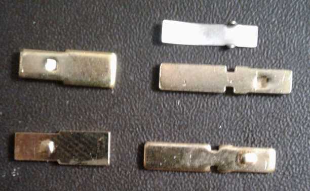 I pushed the gold plated pins out
of a socket
(left) and
a plug (right) with small pliers. (I lost one spring piece.)
(If I was designing them, for off-grid wiring use,
the pins' interconnection length would be longer -
about 10mm instead of 8 - so the plugs wouldn't
pull out so readily if the cord is tugged. But I
think here I'll just work with what's available.)
T-Plug Triplex Wall Receptacle
(31st) The sets of 50 T-Plugs
and 50 T-Sockets arrived. They seemed to mate nicely and securely.
While the model airplane people seemed to think they were good for 40
or 60 amps, I decided a good rating for household use would be about 20
amps. (20 amps times 12 volts is only 240 watts. Oh well. It should
work great for small appliances such as LED lighting and charging small
device batteries.)
It's unfortunate that they didn't use a high temperature
plastic for fire safety - then they would be perfect. I decided to
ignore that for prototyping. I might have to push the pins out of the
shells and insert them into nylon ones. (They proved to slide out of
the shells pretty easily when pushed from the [clean, unsoldered]
solder end. They should insert as easily into nylon shells. Shoulders
on the pins prevent them from inserting too far in.) And anyway there
should be other wiring types besides solder-on: crimp-on and screw-on,
which will need their own pin stamps and shells. (Those will be made
10mm, even if the existing plug blades only insert to 8mm.)
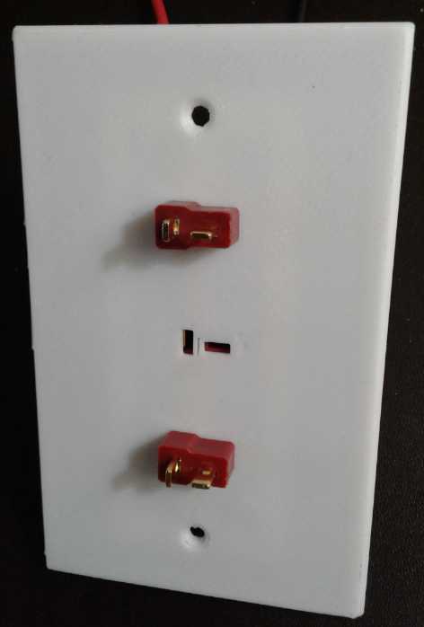 T-Socket Triplex Wall Receptacle
Plate
with a couple of loose T-Plugs plugged in.
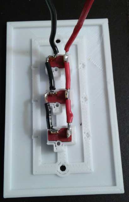 In
the
late
evening
I opened my "3D printed wall
receptacle plate" file and modified it in OpenSCAD so the T-Sockets
would slide in,
and a simple screw with a washer could hold them in place.
Then I sliced it with Skeinforge (fastest to print) and
printed it in PLA. I seemed to have got it pretty good on the first
try. The spaces to insert the socket shells were so close as to be a
great friction fit on all four sides. I didn't bother with the screws.
The blade holes were slightly off
relative to that and their positions had to be adjusted.
Skeinforge had as usual made my thin and critical supports
hollow, deciding everywhere that there wasn't quite enough
width to print a line through the middles - which would have made them
good and strong. The worst was a gap all the way around the hold-down
screws, which also seemed to make the holes larger so the screws fit
loosely. (The user pushes the plug in while the screw keeps the socket
from popping backward out of its slot in the plate, so [except that
they fit so tightly] strength is
needed.)
Having thus disposed of "wall receptacle plates" on the
first evening, the next item will be [was] nylon shells that enclose
the
wires for appliance cord plugs. With that plus higher temperature nylon
shells for the sockets as well, I should think they'll be about ready
for the off-grid market.
[Sept. 4th] I designed and printed
shells for the sockets. I made
prototypes from PLA, but the end products are to be made from higher
temperature nylon for fire safety. Having carefully measured
everything, and having used "Cura" slicer for highest accuracy, when
printed the pins wouldn't fit in. I had to do another one adding .2 to
.5 mm to each inner dimension, and they were still too tight.
In lieu of a real supply, the pins are obtained from the
original shells, which are discarded. The nylon sockets can be inserted
into the PLA wall receptacle plates. Thankfully the whole plate
shouldn't need to be high temperature, just the individual socket
inserts. I found that trying to make wall plates out of nylon was a
wasted exercise: they come loose from the bed during printing, and
anyway are flexible to the point of being floppy. PLA is at least
pretty stiff, and prints well. [In mid September I finally found T-Plug
connectors that claimed to be made with nylon, and ordered some.]
The plugs should be okay with their existing plastic,
because however hot things get, the plug pins are held in place in the
socket until they are unplugged. After the plug is pulled, the
appliance is, well, unplugged. So the thing needed for them is an outer
shell to enclose the ends of the wires.
My
Solar
Power
System
Month of August Log of Solar
Power Generated [and grid power consumed]
(All
times are in PST: clock 48 minutes ahead of sun, not PDT which is an
hour and 48 minutes ahead. DC power output readings - mostly the
kitchen hot
water heater for some months, then just lights - are reset to zero
daily (for just lights, occasionally), while the others are
cumulative.)
Solar: House, Trailer => total KWH [grid power meter
reading(s)@time] Sky conditions
Km = electric car drove distance, then car was charged.
July
31st 798.46, 115.35 => 12.64 [75736@20:00] Sunny with cloudy periods.
August
01st 801.67, 117.33 => 5.19 [oops, left water on (well
pump) for hours; 75748@21:00] Clouds, rain and wind. Welcome to Autumn!
The wind was so steady that the windplant had made about 400 watt-hours
over a 19 hour period when I looked. (I didn't add this to the solar
total.)
02nd 807.42, 120.57 => 8.99 [75759@22:00] A little brighter
but still mostly cloudy. (But any rain has been light - Jungle Creek
has stopped flowing above ground on the beach.)
03rd 814.57, 124.59 => 11.17 [75767@25:00(1 AM)] Mainly cloudy AM,
mainly sunny PM.
04th 817.09, 126.17 => 4.10 [55Km; 75782@22:00] Clouds
& rain.
05th 821.77, 128.82 => 7.33 [55Km; 75797@22:00] Clouds
and no rain.
06th 827.12, 131.85 => 8.38 [75806@24:00] Mostly
cloudy, a bit of rain.
07th (est) => 7.0 -- Cloudy.
08th (est) => 7.5 -- Didn't hit "save" (since 6th) and there was a 1
hour power failure on the 9th. Mostly cloudy.
09th 842.30, 140.75 => 9.58 (est)(=24.08 for all 3
days) [65Km+55Km; 75836@21:00] Mixed sun and clouds.
10th 846.17, 142.92 => 6.04 [75846@21:00] Cloudy. Again.
11th 851.43, 145.87 => 8.21 [25Km; 75857] A few sunny
breaks.
12th 855.56, 148.19 => 6.45 [75862@21:00] Clouds.
13th 858.01, 149.63 => 3.89 [100Km; 75889@21:30] Clouds
& some rain. (Farthest I've driven without recharging. I was taking
it very easy on the highway both trips 55Km+45Km - forgot to plug in
car after trip on 12th.)
14th 860.71, 151.23 => 4.30 [75896@20:30] Mor uv thu
same.
15th 863.00, 152.61 => 3.67 [55Km; 75918@21:00] Rain
rain.
16th 868.64, 154.35 => 8.38 [75927@21:00] Thinner clouds.
17th 872.48, 156.54 => 6.03 [75933@20:00] Surprise
weather: Clouds!
18th 876.62, 158.94 => 6.54 [55Km; 75950@20:00] Mostly
rain.
19th 877.74, 159.56 => 1.74 [75966@20:30] Dark, windy
and rainy.
20th 883.04, 162.52 => 8.26 [75973@20:30] An actual bit
of sun now and then!
21st 889.59, 166.36 => 10.39 [55Km; 75993@20:30] Wow, sun in the
afternoon!
22d 893.59, 168.62 => 6.36 [76000@21:00] Cloudy,
again?!?
23rd 896.72, 170.40 => 4.91 [76009@19:00] Light Clouds, then
Deluges!
24th 900.49, 172.59 => 5.96 [76018@20:30] Cloudy again.
Wither summer? Feels like fall.
25th 902.93, 173.94 => 3.79 [76027@22:30; 55Km]
Clouds, Rain. Sigh. (Car charger "fault", charged next day)
26th 908.75, 177.46 => 9.34 [76042@20:30] mixed sun and
clouds.
27th 910.82, 178.58 => 3.19 [55Km; 76064@21:30] Clouds
and rain... again! (I've started turning on bedroom baseboard heater at
night.)
28th 915.02, 181.04 => 6.66 [85Km; 76092@20:00] Some sunny
breaks in AM, then... clouds and rain.
29th 920.27, 184.18 => 9.39 [76103@20:30] Some sun, some
clouds.
30th 924.37, 186.55 => 6.47 [76113@20:30] Cloudy and
damp, then some sun mid afternoon.
31st 928.45, 188.97 => 6.50 [76121@20:30; 55Km (plugged
in later) Mostly cloudy, a bit of sun.
September
01st 930.38, 190.07 => 3.03 [76141@24:30] Mor cloudz and rain.
02d 932.56, 191.29 => 3.40 [55Km; 76156@20:00] Yet
mor uv thu same.
03rd 937.41, 194.09 => 7.65 [76169@20:00; 35Km] Clouds but no
rain
04th 939.93, 195.45 => 3.88 [25Km; 76192@19:30] same
only darker.
05th 943.57, 197.53 => 5.72 [35+60+35 Km; 76220@20:00]
mor cloudz
Daily KWH from solar panels. (Compare August 2020 with July
2020 & with August 2019.)
KWH
(Each Day)
|
July 2020 (12 panels)
|
August 2020 (12 panels)
|
August 2019 (12 Panels)
|
0.xx
|
-
|
-
|
-
|
1.xx
|
-
|
1
|
1
|
2.xx
|
-
|
-
|
-
|
3.xx
|
1
|
4
|
1
|
4.xx
|
4
|
3
|
2
|
5.xx
|
4
|
2
|
1
|
6.xx
|
1
|
8
|
2
|
7.xx
|
3
|
3
|
3
|
8.xx
|
3
|
5
|
1
|
9.xx
|
1
|
3
|
1
|
10.xx
|
-
|
1
|
1
|
11.xx
|
2
|
1
|
1
|
12.xx
|
3
|
-
|
-
|
13.xx
|
3
|
-
|
2
|
14.xx
|
1
|
-
|
1
|
15.xx
|
4
|
-
|
5
|
16.xx
|
-
|
-
|
1
|
17.xx
|
-
|
|
|
18.xx
|
1 (ONE really sunny
day, a few pretty
sunny, in July!)
|
0 (ZERO really sunny
days in August!)
|
|
Total KWH
|
300.18
|
205.43
|
307.76
|
Monthly Tallies: Solar Generated KWH [Power used from grid KWH]
2019
March 1-31: 116.19 + ------ + 105.93 = 222.12 KWH - solar [786 KWH -
used from
grid]
April - 1-30: 136.87 + ------ + 121.97 = 258.84 KWH [608 KWH]
May - 1-31: 156.23 + ------ + 147.47 = 303.70 KWH [543 KWH] (11th
solar panel connected on lawn on 26th)
June - 1-30: 146.63 + 15.65 + 115.26 = 277.54 KWH [374 KWH] (36V, 250W
Hot Water Heater installed on 7th)
July - 1-31: 134.06 + 19.06 + 120.86 = 273.98 KWH [342 KWH]
August 1-31:127.47 + 11.44+91.82+(8/10)*96.29 = 307.76 KWH [334 KWH]
(12th panel connected on lawn Aug. 1)
Sept.- 1-30: 110.72 + 15.30 + 84.91 = 210.93 KWH [408 KWH]
(solar includes 2/10 of 96.29)
Oct. - 1-31: 55.67 + 13.03 + 51.82 = 120.52 KWH, solar
[635 KWH - from grid]
Nov. - 1-30: 36.51 + 6.31 + 26.29 = 69.11
KWH, solar [653 KWH - from grid]
Dec. - 1-23: 18.98 + .84* + 11.70 =
31.52
KWH, solar + wind [711 KWH + 414 (while away) = 1125 from grid]
2020
Jan. - 6-31: 17.52 + ------* + 10.61 = 28.13 KWH,
solar+
wind [1111 KWH from grid]
Feb. - 1-29: 56.83 + ------* + 35.17 = 92.00 KWH,
solar + wind [963 KWH from grid]
* Now the solar DC system is only running a couple of
lights - not worth reporting. So there's just the 2 grid tie systems:
house and "roof over travel trailer".
One year of solar!
March - 1-31: 111.31 + 87.05 = 198.37 KWH solar total
[934 KWH from grid]
April - 1-30: 156.09 + 115.12 = 271.21 [784 KWH
from grid]
May - 1-31: 181.97 + 131.21 = 313.18 KWH
Solar [723 KWH from grid]
June - 1-30: 164.04 + 119.81 = 283.82 KWH Solar [455 KWH
from grid]
July - 1-31: 190.13 + 110.05 = 300.18 KWH Solar [340
KWH from grid]
August- 1-31: 121.81 + 83.62 = 205.43 KWH Solar [385KWH
from Grid]
Things Noted - August 2020
* Even early in the month, the days were getting notably shorter. By
the 10th it was getting dark at 9:45 (PDT) instead of 10:45 near the
summer solstice; by the 31st it was 9:00 PM.
* There were a lot of clouds and a few sprinkles, but rarely enough
rain to obviate the need for garden watering. (Later in the month the
rains got heavier.)
* But as the month went on, the ground was staying moister - a prelude
to plants going mouldy in the garden and greenhouse in the fall.
* You call this summer? It seemed there was amazingly little insolation
- much the least of any
summer month yet recorded. I thought last summer wasn't very
nice, but this one takes the cake. Even long term Haida Gwaii
residents, and the natives, complained what a crappy summer it has
been. In contrast, August 2019 gave the most solar power of any month
yet recorded. There were eleven days of 10 to 17 KWH - but just two,
with none hitting 12KWH, this August. (OTOH we had no weather
"cataclysms" here, for which we may be
grateful. Maybe next summer will be beautiful like 2018.)
* Usually the windplant does nothing except to go wild in an occasional
storm. In August it had several days when it put out 20-50 watts steady
for as long as 24 hours.
Electricity
Storage
(Batteries)
Turquoise
Battery
Project:
Long
lasting,
low
cost,
high
energy
batteries
Wow... With everything ready to make what should be the
best cell so far... yet again... Sorry, no report!
http://www.TurquoiseEnergy.com
Haida Gwaii, BC Canada


 Then I had another thought.
Originally the straps had fit.
Now they were too tight. The straps couldn't have changed, so it must
be that the battery cells had swelled just a little. Furthermore... none
of
the
cells
that
weren't
bound
tightly with straps had the problem.
And
a battery I'd been given that wouldn't rise above 3.29 originally
had worked fine when I tested it about a year later. It seemed the
cells were having trouble when they were jammed in and couldn't
swell up, just a very little bit. If they had just a bit of room,
they
didn't have a problem. And one I'd been given had even seemed to "fix
itself"
after being left loose for a while.

 If one blocked the entries to the pipes, the water would
rise up and flood a very small area. So the highway would be an instant
dam. One might block, say, the
bottom 5/8 of the lowest pipe, 1/2 the next one and 1/4 of the third,
perhaps with plywood.
Then the water would build up to the 1/2 closed and 1/4 closed pipe and
start spilling over into those culverts, but not quite to the top of
the 5/8 blocked. That one would have a nozzle spraying on a pelton
wheel just inside. The shaft would come out and up so that the
(improved Piggott) alternator was above the culvert pipe. It would be
attached to the wooden cover, as would the bearing for the pelton
wheel. I think that would give sufficient power for LED lights and
fridges in a few nearby houses. It would be consistent power as any
excess
water would just spill over the other gates. (The other two, at least,
would probably have to be removable for heavy rains to prevent flooding
the highway.)


 First thing of
note from the main garden was that much of
the Red Fife had fallen over in the rain. Much of the Kamut was
bent over randomly, but not fallen.
 Peas are one of my favorite garden vegetables. Of three times and
places I planted peas this year, the largest one did great!
 By the end of
the month I had harvested a Kg of
peas and
put them in the freezer, not counting what I had eaten plus some to
plant next year. And there were still some more ripening on the plants.
I picked some of that on September 3rd, putting another 95g of what
I'll call "late season peas" (less tender and sweet) in the freezer and
drying almost as many for next year's seed.


 * Here is a
graph projecting future populations. These are mostly going the right
direction, but it's too little, too late to prevent upcoming
catastrophes.
 [29th] I put
in another lithium battery (misbehaving or not), and then
ran the truck around the driveway. Contrary to my hopes, the vibration
from the unbalanced shaft was pronounced with even a little speed. I
put the truck away, exasperated with the whole thing. Why had
I started this? Then I thought, with unbalanced tires they add
counterweights until they are balanced. Why couldn't I do that with the
shaft? And I had found a strange clamp that went on a pipe, and had
thrown it in a box just days before. It might be just right, or at
least it was the right idea. I dug it out again.
 The T-Plugs were another matter. The top of the "T" cross
was, like on my connectors, the positive terminal, and the in line one
the negative. Noticing the similarity in form and size, I got out one
of my 36 volt "HAT" connector plugs and tried it. The sizes were so
close that it plugged in, and the lamp worked! That made for several
choices:

 In
the
late
evening
I opened my "3D printed wall
receptacle plate" file and modified it in OpenSCAD so the T-Sockets
would slide in,
and a simple screw with a washer could hold them in place.