Turquoise Energy News #154
covering March
2021 (Posted April 2nd 2021)
Lawnhill BC Canada - by Craig Carmichael
www.TurquoiseEnergy.com
= www.ElectricCaik.com
= www.ElectricHubcap.com
Month
In
"Brief"
(Project Summaries etc.)
- Snow - Handheld Bandsaw Mill: Kits? - A New Chevy Sprint EV
Plan - Miles EV Mini Cargo Truck - New Chemie Batteries - Plastic
Recycling - Beehive - Ground Effect Vehicle (R/C model) - More Stuff
In
Passing
(Miscellaneous topics, editorial comments & opinionated rants)
- The Way Forward? Part 2 - Silverware Drainer Mark II - Small
Thots (CoViD) - ESD
- Detailed
Project Reports
-
Electric
Transport - Electric Hubcap Motor Systems
* A New Chevy Sprint EV Plan
* Miles electric cargo truck delayed project - Balancing of new shaft
from motor to planetary gearbox - The Other Things
* EV Efficiency: Better Tires -- Lower Rolling Resistance increases EV
range
* Lawn Tractor Starter Motor Repair
Other "Green"
Electric Equipment Projects
* Handheld Bandmill To Double As Bench-Mounted Shop Bandsaw? -
Commercialization: Kit?
Electricity Generation
* My Solar Power System: -
Monthly
Solar Production log et cetera
Electricity Storage
* Turquoise Battery Project
(NiMnOx-Zn in Mixed Alkali-Salt electrolyte)
- Making New Cylindrical Cell - Trying to plate Zinc - Drawing
copper cans?
It Snew

One expects by mid March that spring is arriving. On the
11th I was thinking about planting seedlings and putting them out in my
window greenhouse. I went for a walk in the rain in the late afternoon.
As I walked it sort of turned to sleet or snow. By evening it was a
blizzard,
and the next day the heavy wet snow broke a 16 foot 2"x3" fence board
and the net over the new "portable" chicken yard collapsed
- in spite of my having gone out and beaten the snow off the net with a
stick a few hours earlier. (The heavy snow fell through the net when
disturbed.) The snow got to maybe a foot deep on the ground. It started
melting, but it froze
each night and kept snowing until the 14th. Snow covered the ground
until the 15th. On the 15th it went up to 4° and really started
melting, and there was bare ground in patches on the 16th. At first it
covered all the solar panels and there were a couple more "zero
kilowatt hours" daily power made. Then it melted off some and I dumped
the snow off a couple of the panels on the lawn, but they weren't all
clear again until the 16th, and there were still patches of snow on the
ground until the 18th.
While there were many things that needed doing around the
ranch, perhaps it was the bad weather that got me working on some green
energy projects again. I didn't get any seedlings planted.
Handheld Bandsaw Mill - Kits?
I had shown my bandmill to Wayne a couple of years ago,
and I had talked with him again recently. Now he contacted me and said
he thought I really had something. He just wanted to help, and said the
design should go somewhere and not be lost through neglect. He
suggested that I should sell plans or kits, and also that it would be
great if it could be
turned on end and used as a shop type bandsaw. Selling plans sounded
like a way to waste peoples' time and energy - there were various
little special parts that had to be ordered from various sources...
just to make one saw?
Selling kits sounded good to me. I thought of the lawn
tractor electric conversion kit I had bought. There were all kinds of
little parts in it that the guy selling the kits had obtained in some
quantity that I'm glad not to be hunting for to get one of each. (I'd
probably still be hunting. But yes, it's still sitting in my storage
waiting for me to have time.)
The idea of using it on end as a shop bandsaw sounded
ludicrous to me. It certainly wasn't made for that, and shop bandsaws
are widely available!
I met with him and he made the point that not everyone has
shop space to dedicate to a bandsaw and the working space it needs
around
it. A bandsaw that could attach to a workbench and then be put away
when it wasn't in use would be just the thing for a lot of people.
Plus, someone who used it rarely could just attach their skillsaw when
needed and not even buy a motor for it. (And a whole low cost skillsaw
is cheaper than most any motor by itself anyway!) Hmm... maybe
something could be made that would clamp the saw to a workbench
and it could be used in a safe manner that way. That would almost make
it a mass-market sort of shop tool. (Eliminating my own shop bandsaw
would free up considerable shop space!) And it could still mill a nice
hardwood tree cut down at somebody's house into lumber in situ, instead
of
the owner having to cut it into firewood.
Wayne also had some good contacts: a company that made
some potentially useful special parts, and one already making various
specialty tools that he thought was honorable and that might like to
manufacture the kits. That actually sounded promising. Perhaps this
should be where my commercialization of products should start? If it's
to start anywhere, a project with a finished prototype that has been
proven to work
really well (it has cut a lot of lumber!) should really be ideal. And
Wayne seems to know how to deal with the specialty tool company for
presenting a new product to them - the agreements to be signed first et
al.
I started by taking video footage of taking apart the saw,
to make a video of it as I had said I would do a couple of years ago.
(I was leery of taking it apart, but I haven't cut anything since I
finished milling the last couple of cants early last summer. And it's
not like I couldn't put it together again in a couple of hours if I
needed it... as long as I'm careful to keep all the parts together.
There's nothing like parts that belong together getting separated. I
met someone who had a whole collection of "tupperware" and not one lid
matched one container! Same with an espresso maker, peanut butter maker
and blender... just the bottoms. And then there's... well, I digress.)
Then I made some wooden "mock-ups" of steel parts that
would be CNC cut then welded together, to get them all fitting together
and then to take measurements of them. But I'll have to make actual
parts and try it out.
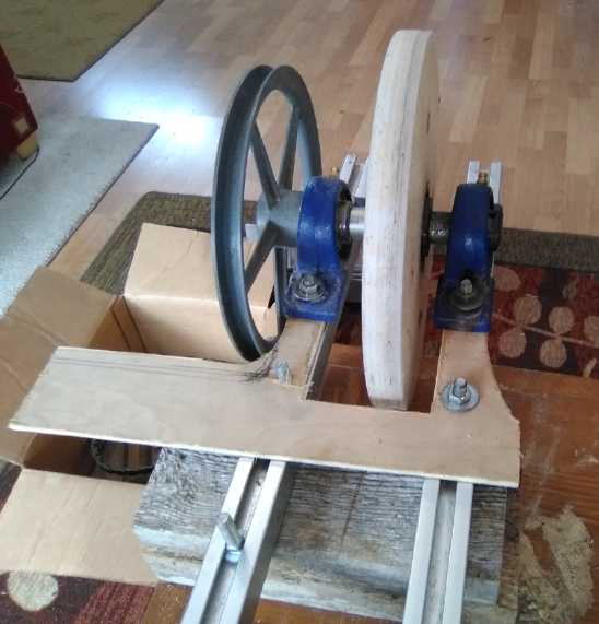 Wooden mock-up of drive side
plate.
Wooden mock-up of drive side
plate.
(Now, how to weld posts onto wood?)
A New Chevy Sprint EV Plan
The original differential from the Sprint's transmission,
installed either in the original transmission or in the experimental
steel box I made, took up the space for the "novel" transmission things
I
wanted to add. It did provide a handy 3.8 to 1 gear reduction. On the
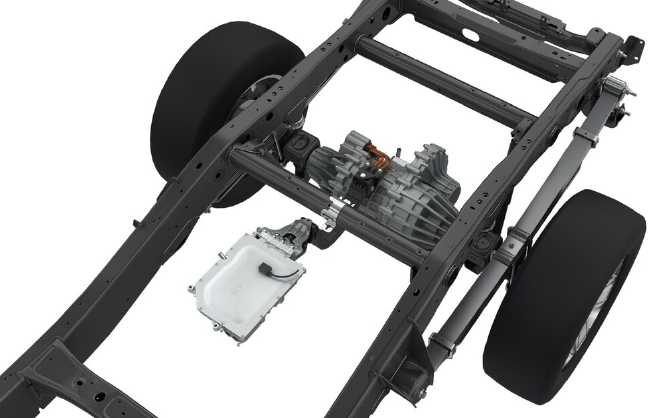
16th I got a group email about a new rear axle with an electric motor
made for pickup trucks.
It was academicly interesting in itself, but somehow it
crystallized some recent thoughts about connecting two motors via
planetary gears straight to the CV shafts of a front wheel drive
vehicle (not exactly a new idea of course)... or... perhaps... to do
just
one motor
to one front wheel in the Sprint.
Where the forklift motor had run the car adequately
with the gears in the original automatic transmission set up fixed at 9
to 1, I now picked 5 to 1 -- and hoped that with the rated 96+%
efficiency it would still climb up my steep
driveway. With the 2000-2500(?) RPM forklift motor, that would get the
car
up to 40-50 KmPH instead of 25. (A 5000 RPM motor would make that more
like 100 KmPH.)
I found a suitable looking planetary gear on
AliExpress.com and it was hardly 30% of the price of the one I got from
Anaheim Automation a year or more ago, even counting the costly
shipping. The working torque spec was slightly higher (210 Nm versus
155) but maximum rated torque was lower (315 Nm versus 465). Well, it's
a light car and a small motor! If 5 to 1 proves to be too low a
reduction, I can buy a
higher ratio one the same shape and size and still be ahead in cost.
(And I have another potential use
for the 5 to 1.)
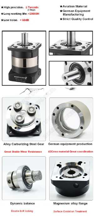 The Gear.
 Procedure:
1. Connect Planetary gear to motor to make a single assembly.
2. Remove one CV drive shaft.
3. Mount motor & gear assembly under hood here somewhere.
4. Connect gear output to remaining CV shaft.
5. Reassemble/rewire everything with the lithium iron phosphate
batteries
- or two stacks of the new lithium ion ones.
Of course this would just basicly get the car rolling.
Eventually I could add the 100% efficient variable torque converter and
then presumably further reduce the planetary final reduction ratio to
allow
higher driving speeds without the motor revving higher. (But at higher
speeds, the forklift motor will probably power the car better
downhill than uphill.)
And - even more "someday" - when I get the CNC router
software going to make molds for the polypropylene-epoxy body parts -
replace the forklift motor with a unipolar Electric
Hubcap type BLDC 'pancake' motor.
Unless I use a more powerful motor than I'm planning on
for now, it certainly won't be a "muscle car". But if one drive didn't
take up too much room, I could add the same thing on the other wheel
and get good power and performance. (At some point there'd be the
possibility of selling kits?)
I decided to wait until I got the gearbox and see how
things
fit together before deciding just how I would install it.
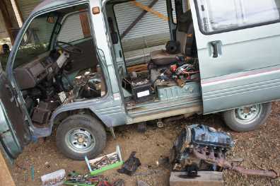
Miles Mini Cargo Truck
The more I thought of the Sprint car, the more it seemed
silly that I hadn't finished with the truck when there were just a few
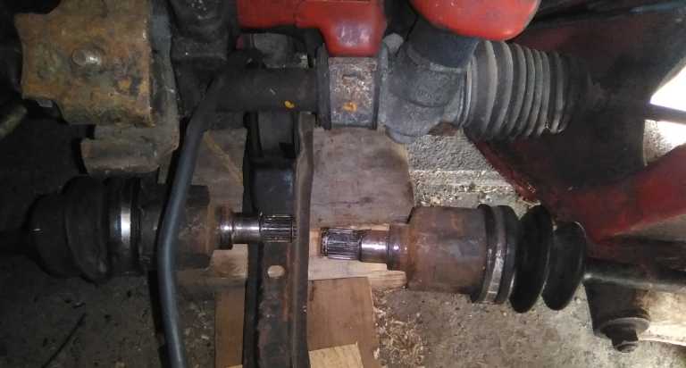
little jobs to do on it. So I finally crawled underneath, removed the
shaft, and supporting both ends on the lathe, got the coupler centered
for balance. Then I took it to Steve to have
it tack welded as he said, "in three places on each side of the
coupler", so nothing could slip or shift during operation. I could
weld it myself, but I'm not a good welder. The vibration from having it
off balance shows that it's a critical piece and
I'd rather have a pro do it than mess it up. I want the truck to run
well and smoothly! I got it back welded at the end of the month.

(After putting that back in there are a few more jobs
before it'll be
working well. => Detailed Report)
Plastic Recycling
I saw a video from people who had developed some giant,
hollow "Lego" type recycled plastic blocks for making walls. It
mentioned "PreciousPlastic.com", and
for some reason I went there. This time I found a link to
"Bazar.PreciousPlastic.com", which had somehow escaped my notice on
every previous visit. (Maybe it's new?) I had been looking before for
the cut metal parts for
plastic recycling machines and found nothing, but finally here was more
than I
had hoped for: people independently making and selling plastic
recycling and
processing parts, kits and machines all over Europe and the world - an
"e-Bay" of plastic recycling equipment.
The prices for some of these 'kits of the essential parts'
looked quite affordable, although obviously the shipping would be
costly. Here (as I also anticipate with my handheld bandsaw mill
kits), deciding to undertake the project is a lot easier with a good
starting point: a kit with the essential and custom components, even if
they aren't complete with all parts.
I decided to order the basic
plastic shredder box kit (assembled), full of rotating and stationary
chopping blades, from a maker in Czech republic. (225 Euros plus 125
for shipping) A table,
hopper, motor and reducing
gear have to be found separately, but the box is the key part.
 The plastic shredder box, with
stainless
steel blades. The shredded
The plastic shredder box, with
stainless
steel blades. The shredded
plastic bits come out the bottom and pass through a sieve.
Pieces too large for the sieve holes (various sieve sizes available)
get churned up and shredded some more. The sized "crumbs"
fall into (any) container placed under the table.
Then at about the end of the month I started looking at a
kit from India that was the essentials of a plastic extruder. (300
Euros - Good price: anything else was just loose parts or much more
expensive.) On the output of the PreciousPlastic extruder is a standard
pipe thread fitting. Therefore, when one designs any mold, simply make
it with the matching threaded pipe fitting or thread for the plastic to
flow in through. Screw it onto the extruder (or injector) to connect
them.
An injector is similar to an extruder, but it has a handle
like a water pump that is manually operated. A batch of shredded
plastic is put in and heated, then the liquified plastic is pressed out
rapidly into a mold by pressing the big "water pump" handle. The volume
of the mold can't be more than what the injector holds.
The extruder keeps on heating and pressing plastic out
with a screw mechanism, and it has a hopper that may be continually fed
more shredded plastic for a continuous process or to fill a large mold.
Some make "lumber" or rods using long pipes for molds. I'd
more especially like to extrude transparent greenhouse panels from
clear food containers, maybe 2 feet wide, perhaps corrugated, and
extrude them to arbitrary lengths, eg 8, 10, 12 or 15 feet long. or
longer! (a 30 inch wide by 10 foot long "Suntuff" greenhouse panel is
over 50$ in
the stores around here, while zillions of transparent plastic food
containers are used once and discarded.)
By the end of the month I was starting to think of the
fact that extruders and injectors need heaters to melt the plastic and
temperature controllers to (what else?) control the temperature of the
heaters. On AliExpress the heaters, which wrap around the injector or
extruder pipe, are called "ring heaters". They specifically mention
plastic injection in their descriptions. "Oven thermostats" would seem
to be the right temperature controllers. I ordered a very few of each.
The other general purpose machine one might want and can
buy would be a plate or sheet press, and I think that would be heavy to
ship and easy enough to make. For small sizes the plate/sheet mold
could be heated in the kitchen oven, then taken out (quickly!) to the
hydraulic press in the shop. Come to think of it, the book press might
be adequate and could be placed on the kitchen counter. I could use
UHMW-PE or HDPE to make molds for making Electric Hubcap type motors. I
could make a couple 500 * 500 * 100 mm, with thick top covers, for the
big unipolar motor. Those would be some very pricey chunks from a
store. (And when you route out the mold cavities, you get back lots of
shredded plastic for the next piece!)
I also saw that molds for the "giant Lego" bricks in the
video were available on the bazar.
Finally I can see getting plastic recycling happening
without bothering with trying to get a financial subsidy. Not that I am
very excited about taking on yet another project, but I know others are
interested and having the equipment should make the difference. And
waste plastic is a HUGE problem! And after all, I still want those
transparent greenhouse panels!
The next question is who and how to involve people. (I do
have a few names.) Definitely some plastic contributors would be
required! (One could even pay some small amount per pound for clean,
sorted plastic scraps. That would give people an incentive to collect
it and do it right.)
 [April 2nd] Hold the
presses, here's a press! One wonders about online spying, but somehow
AliExpress sent me an e-mail with suggestions, the first one of which
was the screw and tube for an "oil press" ("400 grams of oil from 1 Kg
of peanuts"). The screw looked almost identical to those for plastic
extruders! With some examination, it looked like an oil press might
actually work as a ready-made plastic extruder just about as it was,
with a mod or two and nothing much else to buy!
[April 2nd] Hold the
presses, here's a press! One wonders about online spying, but somehow
AliExpress sent me an e-mail with suggestions, the first one of which
was the screw and tube for an "oil press" ("400 grams of oil from 1 Kg
of peanuts"). The screw looked almost identical to those for plastic
extruders! With some examination, it looked like an oil press might
actually work as a ready-made plastic extruder just about as it was,
with a mod or two and nothing much else to buy!
I found a machine that looked really appropriate. It was
over 600
watts and could be set at up to 250°C, with a longer screw and
boasting many features that seemed better than most of the other oil
press machines being advertised. It was the only 120 volt one that said
it would do coconut and hemp oil. If any "oil press" would extrude
plastic for me, this
would be it! And I don't see why it wouldn't. So there went another
371$C... but after all that was substantially less even than the
cheapest incomplete kit at bazar.preciousPlastic.com And free shipping!
Hopefully the only mod will be to put the pipe thread
screw on the "dry waste" (ie, the melted plastic) output. Even that may
simply be a screw-in piece. I expect no oil will come out.
New Chemie Batteries
 Being unable to get a decent coating of zinc on the inside
of a copper can, I finally curled up a couple of thin sheets of zinc
inside the other one and put a cell together. At one point it sat
holding 1.8 volts like it was supposed to, but it had various problems
including almost no current drive and dropping voltages. I ended up
taking it apart without having learned much.
Being unable to get a decent coating of zinc on the inside
of a copper can, I finally curled up a couple of thin sheets of zinc
inside the other one and put a cell together. At one point it sat
holding 1.8 volts like it was supposed to, but it had various problems
including almost no current drive and dropping voltages. I ended up
taking it apart without having learned much.
I'm guessing (a) there was some low resistance path
between the electrodes and or (b) that the agar gel wasn't admitting
electrolyte and hence the ionic connection between electrodes was
tenuous (after all, I'm hoping the agar will exclude zinc ions) and or
(c) that the zinc sheets didn't have good electrical contact to the
copper.
There's about 3 things to do different in the next try:
- double up the separator paper
- impregnate the agar with some KCl salt (...as well as the forgotten
zirconium silicate)
- get a proper layer of zinc on the inside surface of the copper can.
About the end of the month I got a suggestion from Jose to
make a
zinc electrode by electroplating zinc into a piece of graphite foam or
felt, which would be placed around the inside wall of the can, in
contact with the copper. The idea seems very promising. To do it I need
a bigger can - 1 inch pipe instead of 3/4 inch.
 I also made a
new center "+" electrode for the next cell. It took several tries, each
time adding more and more drops of liquid because it was too dry. I
really should measure the liquid as well as the solids!
I also made a
new center "+" electrode for the next cell. It took several tries, each
time adding more and more drops of liquid because it was too dry. I
really should measure the liquid as well as the solids!
(Note: I would like to find something like a big plastic
"straw" to put these electrodes inside to slide them easily into the
cell
along with the separator sheet. Then the "straw" would be pulled out.)
Bees!
I had been trying to get a hive of bees. (Do I really like
honey that much? But it was partly just to get some better pollinators
around here.) Al from Sandspit was buying more bees and had made the
connections to get them here from BC Bee (I think he's the only person
on Haida Gwaii who keeps them), and he added an extra package of them
for me to his order. From Australia, I believe. They arrived on the
25th and with his help and guidance we set the hive up on the lawn.
It's rather early for around here - there was a foot of snow two weeks
ago (and more in the forecast on the 26th!) and almost nothing was in
bloom except the almond tree in my greenhouse. I put in a feeder with
sugar water, and Al provided a pollen package supplement.
A package, this one a screened wooden box in a cardboard
box with perforations, typically has 3 pounds of bees - 3000 of them,
with a queen in a small container. Next day there were dead bees
everywhere around the hive. Hundreds. The sugar water was leaking out
of the upside down bottle feeder at the hive entrance. There wasn't a
lot of buzzing from inside. I hope I don't end up with nothing for all
the money I spent on this!
Of course setting up the beehive took the afternoon, and
then I started getting onto the many things that weren't energy
projects that I had been shoving aside. Gardening for example has a
schedule, and I hadn't even planted seedlings yet. Various taxes and
things needed attending.
Ground Effect Vehicle (R/C model)
I did however finally manage to get the model's radio
receiver
to microcontroller to motor controller wiring done. Next: programming
and debugging the microcontroller. The project creeps forward with the
snails and turtles
passing me by on both sides.
 Here is somebody's idea, apparently to generate electricity while
driving. It seems to be not very well understood that generators merely
convert mechanical energy to electrical energy. Whatever electricity is
being made comes from extra power delivered by the motor to turn the
wheels. (The alternator is probably spring mounted to maintain chain
tension.)
Here is somebody's idea, apparently to generate electricity while
driving. It seems to be not very well understood that generators merely
convert mechanical energy to electrical energy. Whatever electricity is
being made comes from extra power delivered by the motor to turn the
wheels. (The alternator is probably spring mounted to maintain chain
tension.)
It is however the very sort of configuration I might use
to
directly
drive a car wheel from a rear-mounted motor. And somehow from it, I got
the idea to put a rod or beam between that motor and the axle or
independent wheel mounting, to hold the motor at an exact distance from
the wheel to keep the chain linkage tight, yet without adding the motor
to the unsprung weight. (Another improvement, on a
project I haven't yet even come close to starting on!)
I looked at my Toyota Echo and can see an "L" shaped
support would
have to be welded preferably to the bottom plate of the rear coil
spring, to move with the wheel. Then there would have to be a hinge to
allow the wheel
suspension to go up and down without moving the motor up and down. It
might be tough to get the alignment just right as the car wasn't made
to
accommodate such a thing.
Alternatively there can be an "idler" sprocket to maintain
tension
on the top side of the chain with varying distance between motor and
wheel (like on the bottom side of a bicycle chain). But that would
probably make backing up tricky.
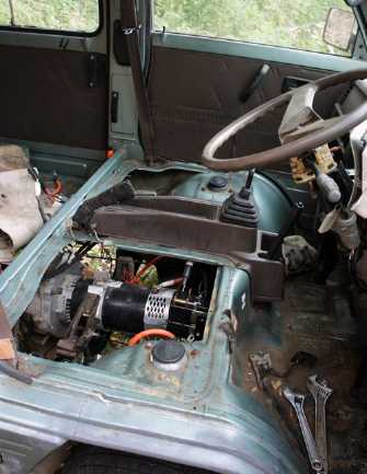 TE News reader Ron in Australia
is converting a
Suzuki van to electric. Should be nice!
TE News reader Ron in Australia
is converting a
Suzuki van to electric. Should be nice!
Amazing how tiny an electric motor can be compared to the petroleum
engine it's replacing.
(Hey, the steering wheel is on the wrong side! Oh ya... Australia.
It's south of the equator so they drive on the left. Ya, that must be
it!)
Joker April
first started with a thin layer of snow on the ground,
which was then washed away with a deluge of rain. After a cloudy spell
there was more snow with hail, which quickly melted. Then the sun came
out for a bit before it settled back into the usual clouds with drizzle.
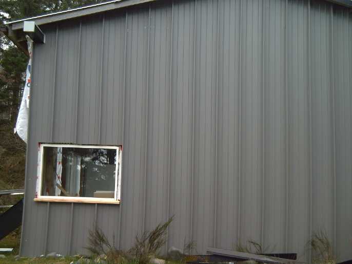
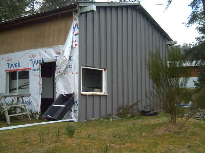
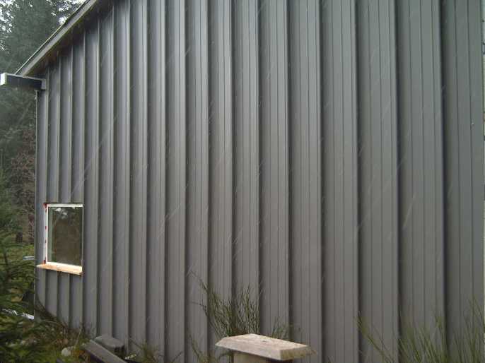
In the next day or two I finally finished the siding on
the East wall of the cottage. (A couple of people have asked for
pictures.) One down, three to go.
 Awk, hail! Then more snow! (April
7th!)
Awk, hail! Then more snow! (April
7th!)
In Passing
(Miscellaneous topics, editorial comments & opinionated rants)
The
Way
Forward?
-
Part 2 (Solutions)
"You never change things by fighting the existing
reality. To change something, build a new model that makes the existing
model obsolete."
- R. Buckminster Fuller
It is a sobering thought that every past civilization on
this planet has collapsed and there has been no continuity of laws and
government from one age to the next. Ancient Egypt, Greece, Rome, the
Incas, the Mongols and the Han dynasty have not simply evolved and
adapted over all these centuries: they each had a brief period in the
sun are all long gone. One might say that their technologies,
communication and knowledge bases were inadequate and incomplete
foundations on which to build permanent civilizations. Today these
factors have advanced tremendously and they are still rapidly improving.
Yet many negative things are happening today with many
diverging paths in sight for our societies. These are in many ways a
result of the incomplete "scaffolding" foundational models of running
societies that we have inherited from past generations. With our
rapidly expanding new technologies and exploding knowledge base, let us
set a new tone and focus on new models, and figure out which paths are
the best ones to take. In democracies we need evolution, not revolution
to move
forward. The citizens of a democratic nation already have the final
authority over the direction of governance when we are able to exercise
it wisely. So if we are having unwieldy problems that seem to have no
simple solutions, as Fuller put it we need to dream up new models for
how things could work better. If a model truly is
better, it can be adopted, at once or perhaps bit by bit or here and
there in local communities, and the present model
will be canceled or just gradually disappear.
It is easy and comfortable to want to keep things the way
they are and many of every generation have wished for that, but it has
never happened. While we may (or may not) maintain social stability as
things change, we are either growing and evolving or retrogressing,
and in many directions all at the same time. And who of the many
wishing for things to always
remain "the way they are", would ever want to go back to "the way
things are" that people wished would never change 50, 100 or 200 years
ago? Our scientific and technical progress over those time spans has
been immense. Overall we live much longer, more safely and more
comfortably.
But in many ways our societal and spiritual progress
hasn't matched that
of our science and technology, and in some ways we have regressed. Many
problems today are a
result of that large discrepancy. We see things we don't like
happening, often enabled by science and technology,
and feel like we have "enemies" who are doing them. Separating,
divisive thinking occurs because of our lack of societal progress, but
again there is no "them", just "us". Remember that today's enemy is
often
tomorrow's friend. (Think of all those veterans, both German and
allied, who fought each other violently in 1944, and for decades later
all got together in Normandy annually to remember the "D-Day" period
and hear it from another person's and the other side's perspective. And
the
European Union of course includes Germany. European nations and
countless persons have become friends. Someday you may respect and even
admire one who you once thought was your enemy, and all nations will
eventually be friends.)
New Model #1
As I said in Part 1 ("The Problem"), hand
in hand with our individual increasingly divisive thinking, our
institutions, having been unable to remain "the way they are" in the
face of
changing conditions, have also over the decades come to be more and
more separate and divided with
each working more and more for itself than seeing itself as a component
of an interwoven
fabric knitting society together. This seems to apply to institutions
of all types: economic, political, military, social, educational and
health.
A new, unifying model could be the reframing of all our
organizations, our institutions, to be value oriented rather than
objective oriented. In this they would explicitly hold the core human
values, the ones embodied in human DNA or epigenetics*, as their core
organizational
values and develop morality and ethics in actions that embody those
values, as a person would. It must be recognized that the ultimate
stakeholders in every organization are... EVERYBODY! All of society and
future generations. If they all work together for society and are
concerned equally
for each individual, fairness should start to prevail, society will
become
stable and everything will progress together.
Fairness for all involved more directly, fair value for
everyone's contributions, positions and legitimate stakes within the
organization must also be recognized. Without that, no one will be
truly
interested in running and maintaining the organization and it will
wither and be lost.
Here we have again the need to be fair to individuals in order to be
fair to society as a whole. This is a failure of what is often termed
socialism or communism: the good of the individual is forgotten; the
good of every individual is subservient to the good of the whole. But
the whole is entirely made up of individuals. The whole - the society,
nation or civilization - can't be maintained and improved without
respecting the rights and life, and fostering the growth of, each
individual that it is made up of.
Only when all organizations recognize that their primal
duty is to assist their entire society and the individuals in it to
survive and thrive with every other objective, however important,
challenging or relevant being secondary to that, will that society
become
cohesive, stable and eventually sustainable. That will take a whole new
mindset
from today's divisiveness, separation and intense competitiveness,
moving to inclusiveness and cooperation, and it
may take a couple of generations for such an "about face" to really
start being embedded into our epigenetics and start to "come naturally"
to most
everyone.
The changing conditions we are entering into will surely
tend to favor trending toward this new mindset.
New Model #2
Concerned and discerning citizens often see situations and
developments that need addressing and aren't being satisfactorily
addressed, but feel - and today mostly are -
powerless to do
anything about them. Thus we get ineffective letters to elected
representatives who usually pay them little mind among 100 other
things they have to do if they even get by the secretary, and
demonstrations and protests in the streets, which are usually
ineffective because the problem hasn't been framed in clear terms,
solutions haven't been thought out, and no one feels any responsibility
for, or perhaps any possibility of, finding solutions to vaguely
defined problems having conflicting interpretations by various people.
So the talent and creative thought of the citizenry is
going to waste and at the same time problems aren't being solved: those
elected operate in an information vacuum where they don't really know
the needs and wishes of the people, much less know the specifics in the
sort of detail that would point a clear direction to proceed. People
everywhere need to be able to have effective input to government. There
are people of intelligence all over who have given thought to various
topics that aren't "on the radar" of those elected, and to whom that
topic is an important concern. Today uncounted "lesser" issues have
been simply pushed aside and never dealt while the topics on the
present agenda of the politicians are pursued. Thus societal concerns
have gradually piled up over the decades, even a century and more,
without ever being looked at. Or having been looked at once,
legislation then [hopefully] appropriate has been "set in stone" and
"the rules" don't respond or correspond to changing conditions. The
whole of governance gradually has become largely "ossified" and unable
to adapt and evolve to meet changing conditions and needs.
Here is where what we might perhaps call the "Ad Hoc
Social Issue Design
Team" can come into play. These are groups of perhaps 5 to 10 people
having members assigned specific functions that constitute it an
organized working team, working toward a specific goal of defining the
problem clearly and coming up with clear recommendations for action by
government. They are composed of concerned citizens focused on a single
topic who want to create a new model for it that will be seen as one
desirable to adopt, and so which is likely to be adopted in legislation.
Then, using the internet, multiple such groups will
communicate with each other to reach an overall consensus to submit.
This provides a path of feedback between elected government and the
more active, discerning, thoughtful part of the citizenry which is
desirous of and capable of finding or creating better models. Elected
representatives will still be responsible for final decisions, but the
wishes and the needs of people will be much better understood by those
in government -- will be clearly defined with clearly conceived ideas
for obtaining the most desirable outcomes before they are brought to
the attention of government.
Once the goals have been accomplished, teams may disband
or continue to meet to review the results obtained, for potential
refinement or modification.
A paper detailing the structure and operating procedures
for such teams has been written by Daniel Raphael, among his many
writings pertaining to the advancement of society toward "days of light
and life", the envisioned utopia that this planet will eventually
become. It can be found free on line at https://BigMacSpeaks.Life/list-documents-by-daniel-raphael/
-- "Paper - The Design Team Process".
It is easy to be pessimistic and say "That's all well and
good in theory, but these things will never be adopted in real life."
However, things are changing rapidly and we are facing a crescendo
of increasingly difficult problems that will not be solved while
decisions affecting the many are made in a vacuum of information and
understanding by the few. The hard times we are entering will
probably be a grand
opportunity for people everywhere to re-examine what they are doing and
why, and
where the directions we have been going are taking us. "Us"
and "them" didn't work. It's all just "us", and trying to blame all the
problems on a
"them" hasn't worked. And then the recognition that we truly need to
create and adopt new models will start.
Our general societal outlook as individuals will also need
considerable change in order to make such new models entirely
effective. In fact, as I begin to discern all sides of separating,
divisive and
negative thoughts around me, I also start to recognize them in myself.
As Jesus said (something to the effect of): If you want to get the
sliver out of your neighbor's eye, first get the branch out of you own
eye so that you may see more clearly how to help.
* I don't like to beat on these "core values of being
human" again and again, but they are a key to building sustainable
societies, and a prerequisite to understanding the articles in which
they
appear. For this reason and also for ready reference, I'll list them as
a footnote whenever I've referred to them explicitly.
- Life
- Equality (equal consideration for each individual including oneself)
- Quality of Life
- Growth (living is growing!)
- Empathy
- Compassion
- Love (in general terms, for existence and for all humanity)
One expects that people all over the world in every
culture and society will agree on the primal value of Life and the next
three, the "primary values", and will surely recognize that those
things won't be attained and sustained over time without the last
three, the "secondary values". One also sees that other English words
or terms might be substituted for the ones employed, especially for the
last three. Words like "fairness", "understanding" and "respect" might
fit well. The seven terms chosen were felt generally to best convey the
intended concepts.
(There is a web site: 7CoreValues.org)
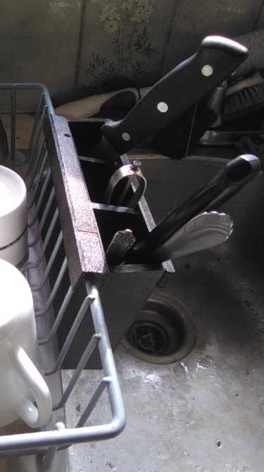
Silverware
Drainer
Mark
II
Only long time readers (and
probably few of them!) will remember I got fed up with any silverware
drainer one could buy for a dishrack and made my own out of ABS plastic
(TE News #43). That got lost when I moved, and finally, when pulling a
fork from the wire one I got with a another dishrack a couple of years
ago it caught and pulled off the whole drainer and dumped all the
silverware in the sink, again, and I finally hit my limit. I stopped
washing
the dishes and went out to the shop and made a new one. This one is 5
inches deep instead of 4-1/2, and is wider. In fact it is 3 separate
compartments instead of 2. The bottom is solid but there are drain
holes in every corner and along the edges. (A screen bottom might be
better? - provided it wouldn't wear out or grab hold of the
silverware.) The depth doesn't bury teaspoons but holds even long
knives well - things aren't always trying to tumble out of it.
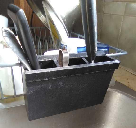
Silverware
Drainer - Three
Views
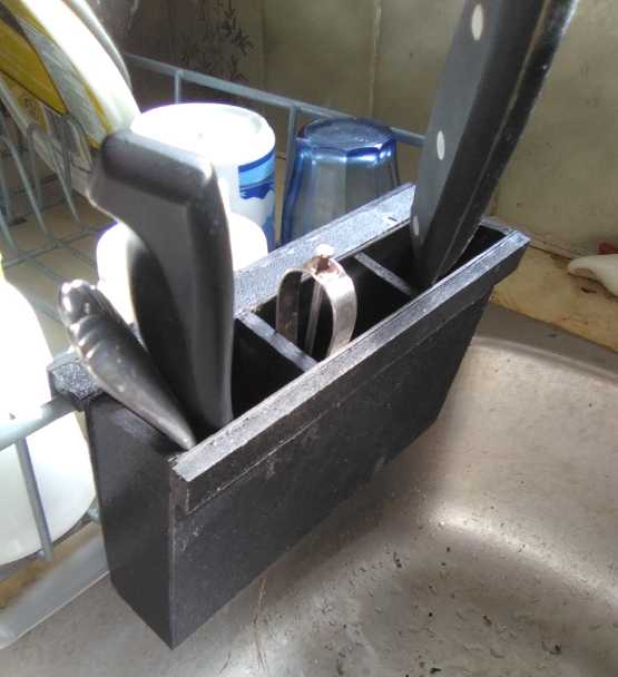
After I had finished it and put it on, I thought of two
potential further improvements. The first was that the compartments
could have different depths. Teaspoons and other other short items
could go into a shallow compartment, and longer ones into the deeper
one(s). And the deep one could be wider for spatulas and the like.
Well, that may be making too much of it. This one will already hold
many more items of various lengths than any of the crappy ones supplied
with
dishracks.
The other was that, well, why is the lip that hooks onto
the dishrack so short? It could just as easily be half an inch or even
an inch long to prevent accidentally knocking it off the dishrack.
Small
Thots
* How did temporary lockdowns "to slow
the spread" of CoViD-19 in order that hospital emergency rooms wouldn't
be
swamped turn into long term lockdowns and business closures "to
eradicate the disease" - surely an unrealistic goal?
* This video is critical of lockdowns, as is the World Health
Organization (WHO):
https://www.youtube.com/watch?v=80Vz7tZLuBI
* Also, the US National Institute for Health (NIH) came up with the
statistic that masks have helped
slow the spread of CoViD by just 1.4%. That's not zero, but it seems
pretty negligible for all the trouble and various negative side effects.
* In Peru when Ivermectin was approved for use against Covid-19 in May
2020, the "excess death rate" dropped 14-fold. A new government there
has restricted availability and the rate has climbed back up.
* Now in Europe, Slovakia and Macedonia have authorized Ivermectin for
"over the counter" sales, and now Bulgaria is even making it
free. It seems it has been flying off the drug store shelves. Was this
not the sensible thing to have done everywhere?
* The findings of a recent widely reported Cali Columbia clinical study
seemingly critical of Ivermectin seem dubious because some
members of the "control group" supposedly given a placebo were
said to have
exhibited symptoms of high-dosage Ivermectin side effects. OTOH in the
whole study only one Covid patient out of the 400 died - Thumbs up for
that!
* One doctor says Americans are getting "herd immunity" to covid,
making it harder for it to spread. We may hope it's true.
* In Venezuela you too could be a millionaire!
(Mil = thousand; Millón = million)

...Now if only that would
buy you the sort of things you usually associate with such figures!
ESD
(Eccentric Silliness Department)
* Water has been discovered in the ground on Earth's moon. Is that part
now called
"the dank side of the moon"?
* Some blocked sewage canal recently was said to be costing 400 million
dollars per hour. Luckily the blockage floated off and all the sh*t is
flowing again. (Expect price surges and toilet paper shortages again. WE
have to pay for those losses.)
* "Gold has become the poor man's bitcoin." - Max Keiser
* Dave gave Joan a gift that he thought would light up her face. But it
didn't. She was de-lighted.
* My ("Arakans"?) chickens lay eggs with green shells. I gave someone
some to sell at the farmers' market, but people aren't buying them.
They buy the eggs with brown or white - or even blue - shells.
Somehow I'm sure this must be Dr. Suess's fault.
* Do whooping cranes spread whooping cough?
"in depth reports" for
each project are below. I hope they may be useful to anyone who wants
to get into a similar project, to glean ideas for how something
might be done, as well as things that might have been tried, or just
thought
of and not tried... and even of how not to do something - why
it didn't
work or proved impractical. Sometimes they set out inventive thoughts
almost as they occur - and are the actual organization and elaboration
in writing of those thoughts. They are thus partly a diary and are not
extensively proof-read for literary perfection, consistency,
completeness and elimination of duplications before
publication. I hope they may add to the body of wisdom for other
researchers and developers to help them find more productive paths and
avoid potential pitfalls and dead ends.
A
New
Chevy
Sprint
EV
Plan
Really, using
the original differential from the Sprint's
transmission to connect a motor to the front wheels has hampered
everything I've wanted to do because the
transmission, or just the differential in the experimental steel box I
made,
takes up a lot of space, limiting what more that was "novel" could be
fit in. It did provide a handy 3.8 to 1 gear reduction.
On the 16th I got a group email about a new rear axle with
an electric
motor for pickup trucks, the "Magna e-Beam Axle" and somehow
that crystallized
some recent thoughts about connecting two motors via planetary gears
straight to the CV shafts of a front wheel drive vehicle (not exactly a
new idea)... or perhaps in my case to do just one motor to one front
wheel in
the Sprint. With no offset spur gears anywhere in the drive train and a
single concentric planetary reduction, efficiency should be very high.
Perhaps that in itself would allow a lesser speed reduction in the
gear? An adequate rated planetary gear could be pretty small and light
compared to any other sort of transmission.
This is probably way going out on a limb, but where the
forklift
motor had
run the car adequately with the gears in the original automatic
transmission fixed at 9 to 1, presuming the in-line planetary would be
very low friction I decided to try 5 to 1 - and hope it would still
climb up my steep driveway. With the 2000(?) RPM forklift motor that
would get it up to about 40 KmPH. (A 5000 RPM motor would make that
100.)
I found a suitable looking planetary gear on
AliExpress.com and it
was hardly 20% of the price of the one I got from Anaheim Automation a
year or more ago. Unfortunately the shipping was almost as much as
the gear. (Grr... why won't anybody just send a planetary gear by the
post office? So it's slow... who knows when I'll get around to doing
this anyway?) I
kept looking but even on AliExpress there were just 2 or 3 stores with
such special components to choose from and this one seemed like a good
one,
so finally I ordered it. Still around just 30% of what I paid from
California counting shipping. (No wonder everything comes from China
these days!)
Ratings on the gear FWIW:
Length 149.5mm
Rated Torque: 210 Nm (155 foot-pounds)
Maximum Torque: rated * 1.5 Nm (315 Nm; 232 foot-pounds) (Okay, that's
probably not a whole lot over "adequate". With two motors and two gears
however...)
Maximum Braking Torque: rated * 2.5 (525 Nm; 387 foot-pounds)
Efficiency: ≥ 96% (That's the kind of number I was looking for!)
Max input RPM: 6000 (would be around 120 KmPH or a bit less)
Continual input RPM: 3500 (Hmm, that's only around 70 KmPH or less)
Service life: 20,000 hours
Noise: 65 dB.
Of course this would just basicly get the car rolling.
Eventually I
could add the 100% efficient variable torque converter and then
presumably further reduce the planetary reduction ratio to allow higher
driving speeds without the motor revving higher.
And - even more "someday" - when I get the CNC router
software going
to make molds for the polypropylene-epoxy body parts - replace the
forklift motor with a 12 coil, 16 magnet unipolar Electric Hubcap type
BLDC 'pancake' motor. (Is it just pie in the sky that someday I'll have
time to do all the work involved in that? Except for wanting it to be
an "ourunner" motor to be safe at higher RPMs it's essentially a repeat
of
my Electric Hubcap motor work of 2008-2012 except that I'd be starting
with a very good idea of exactly what I was doing, which should cut off
maybe 5/6 of the development time and effort.)
Unless I use a more powerful motor than I'm planning on it
certainly
won't be a "muscle car". But if one drive didn't take up too much room,
I could add the same thing on the other wheel and get good power and
performance. (At some point there'd be the possibility of selling kits?)
[17th] I went out to the car to size things up. The splined shaft on
the forklift motor seemed to have an O.D. of about 22mm. Should I have
ordered the 22mm input socket version instead of the 24mm? Might have
been a mistake. But better too big a hole than even a bit too small.
Doubtless I can put in some sort of shim. (although that didn't seem to
work out very well in the truck!)
Then I took out the experimental transmission box with the
differential. Let's see, tho, the box might still
be a useful mounting platform... The left CV shaft ends up at the left
(ie port) side wall... and it's about the right width for the planetary
gear. So the planetary might replace the differential and the motor
could bolt to the left side wall, probably a modified left side wall.
Some other pieces presently attached to the box could be removed.
Hmm... a problem with that scenario is that the planetary gear has a
25mm shaft for an output, whereas a splined socket would be the thing
to attach to the CV shaft.
 Next I looked
in my storage for a cut Sprint CV
shaft I thought I had.
It's been an idea of mine that if one made a somewhat flexible mounting
for a motor and small planetary gear assembly, one might dispense with
the inner CV joint and just use the outer. The motor assembly would
pivot a little - and perhaps move in and out a bit - as the suspension
and steering changed the shaft angles. I found it. It looked just
right. The shaft was 23mm diameter and about 5 inches shorter than the
shortest complete CV shaft. It could be cut to any shorter desired
length. (Then the right wall of the box, if it was still to be used,
could perhaps be the plate between the motor and the planetary.)
Next I looked
in my storage for a cut Sprint CV
shaft I thought I had.
It's been an idea of mine that if one made a somewhat flexible mounting
for a motor and small planetary gear assembly, one might dispense with
the inner CV joint and just use the outer. The motor assembly would
pivot a little - and perhaps move in and out a bit - as the suspension
and steering changed the shaft angles. I found it. It looked just
right. The shaft was 23mm diameter and about 5 inches shorter than the
shortest complete CV shaft. It could be cut to any shorter desired
length. (Then the right wall of the box, if it was still to be used,
could perhaps be the plate between the motor and the planetary.)
Something that I'd miss
from the differential would be the speedometer gear. I'll have to come
up with another way to measure the speed. In looking up tire info I
found that the Sprint's are supposed to do 984.2 revolutions per mile.
That's the key: counting the revs to get the RPM to get the vehicle
speed.
- Okay, that's 611.55 rotations/Km.
- 611.55 / 60 minutes/hour = 10.19 RPM (at 1 Km/hour).
(Wow that's remarkably close to my 2008 ballpark estimate of 10 RPM per
KmPH (for the old Toyota Tercel with 13 inch rims) and have
been using ever since, also noting that the Sprint's 12 inch rim tires
weren't much smaller outside diameter than the Toyota's.)
Miles
electric
cargo
truck
delayed
project
While thinking of the
Sprint, I thought of how silly it was to start that when there were
just a few little jobs to do to get the Miles electric mini cargo truck
running. It's been winter, a few months and a few newsletter issues
since I just got tired of crawling under it and stopped working on it.
Balancing of new shaft from motor to planetary gearbox
[22nd] It seemed warmer than most of the winter. The sun was out! I put
some cardboard down on the cement floor and got under the truck on my
back. I removed the new shaft and tried balancing it on two "rails",
one at each end, finding which way up it rolled to, and then pressing
the other side a bit in the hydraulic press. That didn't seem to get it
perfectly balanced, so I tried another tack. I put it in the lathe,
with one end in the 3-jaw chuck and the other in the drill chuck at the
stationary end.
I've never had a dial gauge but recently ordered one. It
hasn't come, so I just set the tool very close to the shaft (beside
each end of the coupling) and put a piece of white paper under so I
could see the gap. Where it was widest I just tapped the other side
with a hammer. This seemed to work better than the rails and press, and
soon everything was pretty well aligned.
It wasn't perfect, tho. I put it back on the rails and it
turned until the side with the unused square key and setscrew holes was
at
the top. Really, just that bit of gap in the metal? I put a screw in
one of the set screw holes, and sure enough, it was almost balanced,
with a very slight preference for stopping about 1/4 turn from that. If
I
put screws in both holes, it would stop with them at the bottom. Being
that well balanced, I figure if there's still any vibration I can add a
screw to balance it, or just screwing on a hose clamp or two
around the coupler or shaft, rotated until the right position was
found, should get it spot on perfect. if necessary.
Steve had said I should put three tack welds on each end
of the shaft coupler when all was aligned so that nothing could move.
My welding skills being what they are, I took it to him to do them for
me. I would really like to get the truck running well this
time! He
said it was ready at the end of the month and I picked it up.
The Other Things
Then there's the handheld programmer. No one had heard
of the problem I'm having with it with the truck. Now I'm thinking
maybe the motor
controller "broadcasts" its ID blind on it data output, so the
programmer sees that it's connected to it, but there's some sort of
break in the data line from the programmer to the motor controller, so
the programmer can't send anything to it or ask it to give its status
information. That's the next item to check out.
Then I have to decide what batteries I'm going to use. For
now I'm only thinking of one set of 100 or 120 amp-hours batteries
taken from
those I already have, (lithium iron-phosphate or lithium ion... or half
of each) For 72 volts that's 7200 or 8640 watt-hours - about 1/4 of
what's in the Nissan Leaf. That should get it to town (not back), but
it won't be doing highway speeds anyway. The truck was more use in town
in Victoria, and
even there I didn't use it much.
Lastly is a charging system, which will vary depending on
which
batteries I choose. Three 24 volt sections will be problematic, so the
72
volts will be divided into two 36 volt sections, each charged
separately. I had been thinking I'd just put two solar panels on the
roof for
610 watts. A question was whether to just lay them flat, or be able to
tilt them toward the sun when parked.
But then I watched a video about a solar powered "Tour de France" in a
converted electric van towing a trailer full of solar panels. It
occurred to me that two more panels could fold down and latch against
the sides of the van without taking up extra space. These two panels
could be unfolded to optimum angles for charging when the truck was
parked.
(Vis: \__
\
)
The two on the roof could still charge while driving, but
would have to lie flat.
Charging from the grid will need a couple of ~40 volt
power
supplies.
EV
Efficiency:
Better
Tires...
Well
Inflated... Somewhat Worn
Lower Rolling Resistance Increases EV Range. or gas
mileage.
Of course steel wheels on
steel railway track have very low rolling resistance. On a level
surface railway cars once set moving will roll on and on. Vehicle tires
on road surfaces are pathetic by comparison. Where the rubber meets the
road must be one of the least efficient aspects of the drivetrain. So
we might suspect that different tires can have a great effect on
rolling resistance and energy consumption. And in fact, when radial ply
tires started replacing bias ply tires in the 1970s, an
approximate 10% improvement in fuel economy was observed.
Today's electric cars have meters that can give us a good
indication of how tires and road conditions affect energy consumption.
Last summer I started looking at the actual "percent charge remaining"
meter. I would typicly come home from town with 52 to 56 or even 58%
battery charge remaining. This winter it's been more like 46 to 50% -
and that's mostly driving at lower speeds trying to conserve. It seemed
to me I could feel that there was considerably more rolling friction in
cold weather, and this was reflected in the "charge remaining" figure.
It also seemed notably worse when the highway was the least bit damp,
which it is much of the time around here.
In addition to increasing the potential range, using lower
currents and less total energy while driving should maximize battery
life.
So I started thinking about getting some different tires.
It seemed like "a pig in a poke" since I hadn't heard of there being
rolling resistance specs on tires, and it would also be a hard thing to
compare between manufacturers. So I was inclined to just look for low
cost used tires, eg, "auto wrecker" type goods, and try them out to see
if
they were any better than those I had. Another reason for using used
tires is that they already have lower rolling resistance than new
tires. Evidently some loss of tread makes them a bit more pliable. or
something. (Some suggest that as the tires lose tread they get smaller,
so they have to make more turns to cover the same distance, tricking
the odometer into reading more distance than actually traveled and
hence indicating "better mileage". This is doubtless true but I don't
think it's a significant factor in most cases.)
I brought home a set from the refuse station that
looked pretty good, but while they were 16 inch rims, they were really
too big outside diameter and I didn't mount them. Later I took them
back.
Someone suggested I
start looking for tire specs on line. I wasn't finding much and someone
else
suggested I add "Nissan Leaf" into the search. This bore fruit: there
was a Nissan Leaf web page with a discussion
about that subject from 2019. To my amazement, there was a consensus on
one particular tire, the Bridgestone "Ecopia EP422 Plus". These, the
discussion seemed to affirm, were better than anything else, even
other reputedly low rolling resistance "LRR" tires from the most
reputed brands. A blend of special materials along with the tread
design was used to help achieve this. They are available in various
sizes. They are a road tire and said to be very good on wet pavement -
Yay! (I don't suppose they're very great in our very occasional snow.)
Armed with this information, it seemed much more
worthwhile to spend the money and I ordered some from Charlotte Island
Tire. They seemed to be taking a while and on the 23rd I thought I
would check on the status when I went into town and passed by. They had
just arrived
when I got there (In fact I had just seen the Tuesday ferry going by my
house
as it was leaving!) and they put them on within the hour.
Perhaps it was my imagination, but it seemed like there
was less rolling resistance even just driving back across town. After
another stop I drove home, and I was pretty sure they were better. The
"kilometers per kilowatt-hour" said "average 7.2" on the highway
instead of maybe around 6.5. And as I left town the batteries said
"73%",
which meant it usually would have been down to about 45% when I hit
home. Instead it read 51%. It was a bit soon to start estimating
percent improvement, but it was unquestionably better.
I drove into town again the next day - partly just to
check the energy use. Unfortunately it wasn't a very typical drive and
had some special variables. I went across town twice (an extra 5Km),
back to the garage at the far end and pumped the tires up from 36 PSI
(Nissan's spec) to 40 - a bit harder ride perhaps, but it decreases
rolling resistance. So it had more air in the tires after the half way
point. I got home with 52% charge remaining having gone 59.5 Km. The
average energy use said 7.5 Km/watt-hour. Again it seemed very good,
even like summer again, but hard to compare with other recent trips.
When I hit even a small downward grade on the highway I
noticed that the "kilometers per kilowatt-hour" bar on the display
would shoot up to the top, "pinned" at 10. I don't remember it
regularly "pinning" like that on the highway before. Maybe once in a
while.
Driving conditions vary. On the 26th I drove to Port
Clements and it didn't seem like a big improvement. And it was warmer
(9°!) and the road was dry so I was expecting better. But then, I
drove faster as I was a bit late, and I drove a few extra kilometers,
and still got home with a couple of percent extra. On the 27th I took a
more typical trip back into town. It was raining and 7°, but I got
home with 56% battery remaining instead of maybe 50% or less,
indicating an improvement probably around 10%.
To get "only" 10% improvement probably means the original
Ironman "Radial RB12" tires weren't as bad as I thought they were. But
the playing field probably wasn't quite level even yet. Worn tires are
supposed to be better than new ones, and it seems to me I had inflated
the old tires to 42-44 PSI, 44 being the maximum rating. I now inflated
the new ones all the way to 43 PSI.
In the next couple of trips, it did seem to do a bit
better. I drove to town (but only to the near end; -3Km) and still had
60% left. 58% was the previous record high, last summer. On the 31st in
rain and cold (5°) I went to town with a side trip up a gravel
road, and still returned with 56%. I'm pretty sure it would have been
well under 50% with the old tires, suggesting improvement of at least
15%. Warmer weather should bring further improvement, and my overall
sense is that the improvement is probably between 10 and 15% -- as I
had hoped.
In spite of knowing how much better steel railway wheels
are, I hadn't thought that there might be room for another 10, 15 or
even higher percentage in regular pneumatic tire efficiency over
"typical" radial ply tires. One wonders how much more might possibly be
gained - safely - and thinks how inefficient the older bias ply type
tires are.
There are novel tires I occasionally see in news articles
that don't have air in them, with various rubbery "wavy ribs" or
"hollow circles" that connect the outer tire surface to the hub. I
would be curious to know what sort of rolling resistance some of these
have, but I've never seen that any of them have made it to production
or had published any info about any aspect of their performance besides
"can't
go flat". (One would expect great handling on corners!)
Someone mentions that the thinner the tire, the lower the
rolling resistance, pointing at the ultimately thin tires of a 10-speed
bicycle. But the tire has to support whatever the vehicle's weight is,
including the sideways forces during sharp cornering. The 10-speed is
lightweight and leans into its turns. I'm no expert but surely the best
"LRR" would doubtless also be solid hard rubber (or blended material),
but thinner, solid tires would probably skid too easily on
pavement and they would surely give a rough ride. (and wear out
quickly?) A sponge rubber sort of interior would be softer but I
suppose it would probably have more rolling friction than pneumatic.
Hmm... What about a tire of thin, solid rubber on a thin
steel rim, with some sort of steel spring 'spokes' between that rim and
the center hub? Would that not ride smoothly and with very low
friction? And entirely "unsprung" weight - thin rubber and rim - could
be extremely low.
There just might be a big potential for improvement there, if it could
be made safe - to corner well and not skid too easily. Might that even
head toward the negligible friction of the railroad wheels?
I found a limitation to the Bridgestone Ecopia tires:
their smallest rim size is 15 inches. So much for putting them on the
Toyota Echo (14"), the Miles mini cargo truck (13"), or the Chevy
Sprint project car (12")! (In fact, I was concerned about finding tires
for the Sprint at all - and it looks like it may need them, with the
rubber on at least one rim splitting open. but there do seem to be some
on line - and they're cheap compared to larger tires! It would also
seem there are 13 inch tires with about the same outer rubber diameter.
That would of course require new rims - which hopefully would fit.
Maybe I shouldn't have discarded the 13" tires from the Suzuki Swift in
2017!...except they had an odd size bolt pattern anyway.)
Lawn Tractor Starter Motor Repair
Two magnets of four in my
lawn tractor's starter motor broke loose form the housing and then
(being hit by the rotor)
broke into pieces. I thought about the electric conversion kit I had
bought, and decided I just didn't have time. But it seemed a new
starter motor was 350$! It sat for months, and in spite of it being
winter there were a few times I could have used it. About the
start of March I tried epoxying the pieces of magnets back in. (Sorry,
I didn't think to take pictures.) I cut a few little wedges of wood to
hold the pieces in place since they all wanted to repel each other and
attract to the other nearby magnets. I didn't glue them all at once,
but only what I could manage at each go. I didn't glue in some small
fragments - too hard.
I put it together and something was hitting at one part of
the rotation. I filed down a bit of magnet or epoxy that I thought
might be protruding to no avail. I then looked at the rotor. One of the
laminates had been bent and was sticking up a bit. I straightened it
and filed it down a bit. Then everything turned freely. I re-installed
it on the lawn tractor and it worked fine, and has done a couple of
dozen starts now.
I was rather disgusted with the sloppy glue job on the
starter motor magnets: the curved magnets were somewhere around
1.5"x3"(?), but the little spot of epoxy holding one of them on was
hardly 1.5" square. No attempt was made to coat the whole back of each
magnet or even much of it. So the first one had broken off and the
forces had bent the stator lamination and dislodged the almost equally
weakly glued second magnet. (The glue didn't break - the rest of the
magnet broke off the small remnant glued spot on the sintered magnets.)
Hopefully no more will break loose, but my level of confidence isn't
high! I don't think my gluings will come loose unless the epoxy somehow
degrades.
I did this once before with an electric lawnmower motor.
First I just took out the pieces of broken magnet (one magnet of two)
and it seemed to run fine but at half power. Then I glued in most of
the many fragments
and it worked full power again. Then the other magnet broke off and I
had to do it all over again! Not so much later (just to add insult...)
someone gave me a perfect identical motor outer case with intact
magnets.
[29th] Sure enough, a third magnet has broken loose! My repaired ones
are fine. [31st] Epoxied and running again. That leaves just one magnet
yet to bust.
Ground
Effect
Craft
(RC
Model)
Why Reverse Throttle?
Someone suggested I phone the hobby shop where I bought
the radio control equipment. I explained about the reverse throttle and
how if I turned off "the remote" (as he called the handheld control
transmitter) with the model on, the stopped motor suddenly roared up to
full throttle. "Always turn the remote off last." he said.
But what if the model loses the signal? "You're more
likely to lose visual orientation first. The transmitters have quite a
long range."
It's nice to hear that the transmitters have a
considerable range, but it doesn't entirely assuage my concerns. The
same person that suggested I call them said his uncle had lost a big
"B-52"
model airplane that he lost control of over a lake. It went out of
range and just kept going. I am still left with my original question of
why radio controls would be made to have the aircraft go full throttle
if the signal is lost instead of having the motor stop. it just doesn't
make sense. A glide is good, but surely even a crash is better than
having your precious model carry on and on, perhaps never to be seen
again. Of course hopefully the ground effect craft will simply alight
on the
water (or flat land) and stop if the motors stop.
Wiring Done (about time!)
[29th] Well, I finally did the wiring, per the pencil diagram. It just
couldn't sit another month! Next: programming and debugging before
actually trying to run the model.
Other
"Green"
Electric
Equipment
Projects
Handheld Bandmill To
Double As Bench-Mounted Shop Bandsaw? - Commercialization?
[5th, 8th] Wayne, who I had shown
my bandsaw mill to a couple of years ago, had an idea that if it had an
attachment or a couple of pieces done differently, it could be clamped
to a workbench vertically and used as a regular shop bandsaw. This
struck me as a little silly at first since there are plenty of shop
bandsaws around. That wasn't what I had made it for!
But if one doesn't already have a bandsaw, a dual purpose
one that could easily be clamped to a workbench as a shop bandsaw as
well as be hendheld to mill an occasional log outside - and then be put
away on a shelf when not in use - might be just the thing for the more
casual, occasional user. Like me for example. Convenient as it is to
have it sitting there when I have some little job, certainly my own
shop bandsaw takes up a good chunk of floor space. And certainly I had
had the thought that the self-adjusting band guides might be a nice
improvement for shop bandsaws.
Wayne thought if it was all done nicely, sets of plans or
kits with the special parts pre-made, they should sell well. I had
thought about these ideas before but had eventually just let them fall
by the wayside. But he's probably right, and the "clamp-on shop
bandsaw" idea would much increase the potential market. He says he
knows a reliable company that he's dealt with before, that makes and
sells such all sorts of such 'specialty' equipment. They would probably
like it.
He also thought to never mind selling the skillsaw and the
readily available parts as pieces of the kit: just make the parts that
needed welding or CNC fabrication. I could see doing that, except I'm
pretty sure people wouldn't want to be sourcing little pieces -
bearings, shafts, special bushings and V-belt pulleys from here, there
and everywhere to put a kit together. Also some would be almost sure to
get ones that didn't quite fit together properly with the pre-made
parts: "brand A" fit fine when I checked it, but they found "brand B"
when they bought one, and something was a little different. So I think
the more of the essential parts that are included in the kit, the
smaller the potential for customer headaches. And while I would have no
objection to selling plans, that's also a good argument for selling a
kit - that few would actually get built from plans, but many from a kit
that mostly just needed assembly.
But the skillsaw itself is the heaviest and most costly
part of all. And one that most users would already have. Most any one
will fit on, and omitting it would substantially reduce the investment.
Depending on how much or how occasionally they used saws and the
bandsaw, some might just attach one they already had, and take it off
to use it as a circular saw again. If they found that tedious they
could buy a second one almost anywhere. I had first put my 13 amp Ryobi
skillsaw on the mill as a temporary power source to see how it worked,
but found it to be a very convenient and perhaps the best solution. To
my mild surprise it had sufficient power to mill lumber (not excess!) -
from just a regular 120 volt power plug! They have their own mounting
plate and trigger on-off switch, and the "cut depth" adjustment makes
it easy to put on the V-belt and adjust the tension.
(My other plan was to make and mount a 36 volt "Electric
Hubcap" motor that could be run off batteries in the bush. That would
of course be a lot more work and in the worst case so far I used 200 or
250 feet of extension cords to reach the alder log where I cut down the
tree, with good results.)
By the end of the month I started cooling on the idea of
using for a shop bandsaw. As a mill it's pretty safe, because to use it
the operator has to stand behind it and have one hand on the skillsaw
trigger and the other on the right side handle. (In spite of it being
most easily pushed along with the knees/legs.) The most dangerous
operation is positioning the saw, where one must be careful not to
press the trigger unintentionally.
As a shop saw, one would have to tape the skillsaw's
trigger switch "on" and attach another "on"/"off" switch in-line. What
happens when you go to use it as a mill again and the trigger is still
taped "on"? Also one is standing on the cutting side and feeding into
it. It would need a guard along the length of the blade to the top
wheel, and a guard on the V-belt and pulleys. (I know someone whose
fingers got pulled around a V-belt pulley, on an air compressor. Not
nice at all!) Clamping it to the side of a bench so the cutting height
is at table height would also be dubious. So it would probably have to
have a whole enclosure that also is a stand for the bottom end, and sit
on top of a table -- or better, a low bench.
OTOH, it's all possible. The question is whether
it's practical. And if the cut could be at benchtop height, it could be
an advantage that the wood would lay on the table once it was cut
instead of falling over a precipice. I have a whole table assembly I
made that I can mount behind my shop bandsaw for that purpose.
I decided to plan it as a mill, and then see what might be
simple to add to make it into a shop bandsaw.
I tell myself that the last thing I need is another
project. OTOH, if money is coming in from a working product, perhaps I
can enlist some outside help for some of the other projects? I think
I'll get on board with this idea.
Size
[14th] I thought about the size of the saw. Wayne thought bigger wheels
would be better - then one could use any old widely available
band/blade. 14 inch wheels are great for a stationary saw mounted
solidly on its own heavy table. But it's the 10 inch wheels that shrink
the whole size of the saw to "portable". I decided to keep that size. I
expect one could put on an "ordinary" band instead of a thin "meat
cutting" band just fine anyway, but I've never tried it. (Maybe I
should.)
I had used 36 inch alaska mill rails as the backbone. But
with 10 inch wheels and a 93 inch band, the wheels actually stuck out
the ends by about 2.5 inches on each end. I had never used the full
cutting width. I think the widest cut I ever made was about 13" at a
protrusion in the small alder log. IIRC I could theoretically have got
a 21 inch cut. But with thin bands and the small motors, is such a cut
width really practical anyway? In a commercial product keeping the
wheels within the 36" length would probably still allow about a 15 or
16 inch wide cut. I decided that would be enough. (Instead of a 93"
band, it would be 83". Or it could be a shorter one by sliding the
undriven wheel end inward. That makes it much more adjustable than a
regular bandsaw.)
Width
I decided the saw was wider than it needed to be front to
back and so to shorten the distance across the rails from 5-1/4" to
4-1/4". (I had about 1-1/2" of spacers on the main wheel shafts
anyway.) This would shorten in front of the band and leave the same
width behind it. The band guide wheels on the prototype wouldn't have
room, but they would be redone anyway and changing their mounting posts
could reduce the width they needed.
Then I thought about tracking. Wider means longer wheel
shafts. Too short would make them touchy to adjust. Better to keep the
5-1/4" width, which seemed to work out well when I was making the saw,
and not make an arbitrary change.
Drive Side Assembly
Next I considered the drive wheel, on the left. I had the
"pillow block" bearings for the shaft bolted to the rails. (There are
also "steady bearings", which are about the same except their bodies
are made of formed sheet steel instead of cast, and hence they're a
little smaller. The saw should be made able to accommodate either
type.) For a kit, I would rather bolt both front and rear bearing to a
single plate, and have the plate able to slide along the rails, moving
both bearings at once. This would be a "U" shape with the end on the
inside. (If the end was on the outside, it would be in the way of
changing the blade.) The legs would have to be about 9 inches long, and
the outer width 4-1/4".
I had also discovered that with a 1.5" plank as a guide
board the saw could only cut 1-7/8" deep. Changing the depth guide
mountings could easily add another inch+ to make it 3 inches. But as it
was I was using it all to cut (barely) 2 inch thick boards. Then, if
there was at least a 1" spacer between the bearings and the rail, still
more depth would be available.
That suggested making an inch thick plate. If it was steel
it would be too heavy. If it was aluminum I couldn't weld the guide
wheel post or other attachments to it. I decided on a 1/4 inch steel
plate. The post would be welded on with angle pieces to hold it rigid
and prevent the plate from bending. Spacer blocks could be added
between the plate and the bearings.
Then I figured that the middle arm of the "U" should be
extended front and back for welding two more arms onto. These would be
to hold the depth adjustment rails. Maybe an inch behind the saw for
the rear rail and 4 inches ahead for the front. The side stop could
cross and weld to all three arms (legs?) and add strength. And all this
should probably act somehow as the assembly for clamping the saw to a
workbench for shop use. The side stop might also become the "table" for
when tipped up on end for shop bandsaw use.
At this point it was getting complex enough that I figured
I should try to draw it, or even make one. Then I thought of doing a
wooden mock-up: easy to do and put together, easy to cut more pieces
for any that didn't fit right. CAD? Maybe after I had the mock-up! I
doubt if OpenSCAD will generate the right files, and I use the 2D CAD
program so rarely I don't even remember its name, and I'll have to
learn to use it all over again! (I'll have to look it up in some old TE
News. Maybe I put in the name and some tips for using it somewhere?
"LibreCAD"?) However, the CNC waterjet people will need the CAD ".DXF"
files in order to cut pieces for the kits. Even if I ever get the CNC
plasma cutter table going it'll need them.
Undriven (Right Side) Wheel Mounting
On the other side, the guide wheel assembly has to be
separate from the main wheel mounting. Otherwise the cut width
(distance between guide wheels) can't be adjusted except by getting
different length blades/bands. And the wheel mounting has to be movable
to slack it off for changing bands as well as for slightly (or even
very) different length bands.
In making the mockup of the drive wheel side, at first I
thought the one for the other wheel could be more or less a mirror
image of that. The left (driven) wheel assembly also holds the post for
the left band guide wheel and the posts for the front and rear guide
rails that set the depth of the cut. But if the right end posts for the
rails were similarly affixed to the right wheel assembly, the
left-right length between the two assemblies would make it impossible
to adjust the band length and tension without loosening the rails. So
the posts holding the right ends of the rails also have to be a
separate assembly from the right wheel assembly. Thus the right wheel
assembly only holds the wheel itself.
Most shop bandsaws have one screw to tension and
de-tension and another to adjust the alignment (or "tilt") of the
wheel. But they also have an open ended shaft. My shafts have a bearing
on each end. So it has been more convenient to have two adjustment
screws which do both jobs together. The prototype's arrangement has
been workable but tedious.
Now it occurs to me that, with the shaft and bearings not
being right at the end of the backbone rails, I could put a cube onto
each rail end, each with a screw having a knob for easy turning, that
would thread into the two ends of a "U" block that holds the bearings,
similar to the one on the drive end but without all the attachments.
Thus the blade would be slackened for replacement by turning both
knobs, then retightened with both and the tracking adjusted by varying
the tension between the two. That's probably about the most practical
solution for this saw layout. The wheel's "U" plate bolts would be held
"loose" on the backbone rails with two nuts tightened against each
other. Thus the plate would be prevented from moving up or down but
could move in and out, and could twist a little left or right to align
the tracking.
Right Side Cut Depth Rail Adjustment Posts
A single "I" mounting plate running across the two
backbone rails would hold the right end front and back posts, in line
with the left end posts on the left wheel assembly. At first I thought
they could be just long enough to reach the band and have a reinforcing
bar between them, somewhere near the ends but out of the way of the
cutting band. But a reinforcing bar anywhere inside the band would
prevent setting the cut to that depth.
That leads to the idea that they should instead stick out
past the band and a flat strength piece welded on the ends, but that
would prevent installation and removal of the band!
I guess they should be made sufficiently strong to each be
freestanding, welded only to the "I" plate.
On the 25th it occurred to me that if the adjustment rails
could slide left to right inside short square tubes, and the tubes were
clamped to the posts instead of the rails, that the posts could after
all be welded to the right main wheel assembly plate without causing
problems. That eliminates the "I" plate, which allows the right band
guide wheel mounting to get closer to the right wheel for widest cuts.
Right Side Band Guide Wheel Post
The right end guide wheel has to be able to move left and
right according to the width being cut. To simply have it 16-18 inches
from the left end guide wheel leaves much play for wavy cuts in cutting
(eg) 6 inch wide boards. Better to move the wheel so there's only (eg)
7 inches between them.
Thus suggests yet another "I" plate across the backbone
rails to hold this post. It would have to be inside from the depth post
"I" plate, further limiting the maximum cut width... unless the post
and guide wheel could be offset from the "I" plate and moved past the
glide rails "I" plate to get it next to the right end main wheel
without the plates crossing. Maybe a cross plate welded to the "I"
plate with just enough clearance over the other plate, and the post
welded ot that?
Motor Mounting and Top Cover
I have an extra objective for these covers beyond the
prototype: Minimize the number of screws that have to be removed to
change the blade/band. A stiff cover attached to the front rail could
mostly "float" at the back with a small gap between the rear rail and
the cover. Thus the blade could be removed through the gap. But I think
the section holding the skillsaw, and the piece holding the right hand
grip handle need at least one solid connection to the rear rail, one or
maybe two bolts each. That might make:
a) loosen the 2 screws to slacken off the band
b) Take out the screw(s) holding the back end of the motor mounting
c) Take out the screw(s) holding the grip handle on
d) Probably have to take out the 2 screws holding the guide wheels on
to get them to let go of the band.
That's 6, 7 or 8. If they all had knobs it should still be
pretty simple.
Mockery
I soon cut a
shape and size for the driven wheel's base
from 1/4" plywood. But I can see I'll have to make real parts and run
it before trying to make a kit of it.
Electricity
Generation
My Solar Power System
Month of March Log of Solar
Power Generated [and grid power consumed]
(All times are in PST: clock 48 minutes ahead of sun, not PDT which
is an hour and 48 minutes ahead. DC power output readings - mostly
the kitchen hot
water heater for some months, since its removal mostly just lights -
are reset to zero
daily (mostly for just lights, occasionally), while the others are
cumulative.) Note that the DC is actually power used since there's
nothing totaling up the amount incoming to the batteries, which is
(unless it's a lot and there's little sun) replaced the following day.
Solar: House, Trailer => total KWH [grid power meter
reading(s)@time] Sky conditions
Km = electric car drove distance, then car was charged.
February
28th 1234.55, 379.51 => 1.30 [82730@18:00] Clouds & drizzle
March
01st 1236.68, 380.98 => 3.60 [82757@17:30] Light overcast
02d 1239.45, 383.05 => 4.84 [82785@17:30] Variable light
overcast, rain.
03rd 1241.57, 384.41 => 3.48 [55Km; 82821@18:30] More overcast.
04th 1241.79, 384.58, .4 DC => 0.79 [82860@21:00] Gales and
rain. Mains power was off for a while. Used DC/battery power with
inverter to make a pot of coffee in coffeemaker.
05th 1244.42, 386.40 => 4.45 [90Km; 82897@19:00]
06th 1246.49, 387.69 => 3.36 [55Km; 82933@18:30] Rain, clouds.
07th 1249.04, 389.46 => 4.32 [82968@19:00] A bit of sun, but mostly
more rotten weather.
08th 1253.63, 392.14, .1 DC => 7.37 [not read] A nice, sunny day!
(Yay!)
09th 1257.95, 394.80 => 6.98 [65Km; 83029@19:00] Frosty AM, mix of
sun & clouds but pretty cold.
10th 1262.73, 397.90 => 7.88 [20Km; 83059@18:30] Sunny AM then
clouded over.
11th 1263.95, 398.63 => 1.95 [83087@18:00] Clouds & rain. Hit
7°. Snow late PM.
12th 1264.07, 398.65 => 0.14 [83120@19:30] Blizzard! Snow covered
the solar panels.
13th 1264.29, 399.15 => 0.71 [83152@18:00; 55Km] Snow still covered
house panels at end of day, but cottage panels were clear. In the
afternoon I dumped the snow off 2 of the panels on the lawn and
discovered they weren't producing anyway. There was a bad connection, a
green corroded pin at an MC4 combiner (presumably the "+" side). I
plugged it in and out a few times and put some vaseline in and around
the connection. (For how long has it been working poorly?)
14th 1266.70, 401.85 => 5.11 [83185@19:30] starry sky, frozen solid,
overcast, sunny, +2°, snow, overcast, sunny (some snow melt), hail,
sunny, scattered clouds, 0°. Some solar panels at house still
obscured with snow at end of day.
15th 1268.49, 403.49 => 3.43 [83210@20:00] Light overcast. hit
+5°. Still 2 panels snowed in.
16th 1271.06, 405.09 => 4.07 [50Km; 83248@19:00] Overcast. Solar
panels clear.
17th 1273.70, 406.95 => 4.50 [45Km; 83282@18:00] Overcast. +6°.
Most of the snow is gone.
18th 1274.83, 407.50, .1 DC => 1.78 [83314@20:00] Overcast. +7°.
19th 1278.43, 409.83 => 5.93 [85Km; 83347@19:30] Light overcast.
20th 1280.42, 411.09 => 3.25 [83382@18:30; 55Km] Light overcast,
later rain.
21st 1283.70, 413.19 => 5.38 [83424@21:30] More rain than sun.
22d 1288.22, 416.12, .1DC => 7.55 [83452@20:00] Sunny
afternoon.
23rd 1290.27, 417.40 => 3.33 [55Km; 83491@19:00] Rain.
24th 1293.75, 419.59, .1 DC => 5.77 [60Km; 83526@18:30]
25th 1297.93, 422.44 => 7.03 [83554@20:00] Some sun today - mostly
dull sun.
26th 1300.23, 423.84 => 3.70 [90Km; 83598@20:30] Clouds, again?!?
Forecast SNOW again?!?
27th 1302.83, 425.72, .5 DC (oops, lights left on) =>4.98 [55Km;
83637@20:00] Rain (no snow), light clouds, sun late PM. AWG!
Temperature dropped and Snow after dark!
28th 1306.94, 428.40 => 6.79 [45Km; 83667@18:30] Snow melted. Mostly
sunny PM. Still quite cold (4°?).
29th 1311.53, 431.67 => 7.86 [50Km; 83701@21:00] Warmer, fair bit of
sunshine.
30th 1314.09, 433.31 => 4.20 [83733@24:30] Cloudy AGAIN
31st 1316.28, 434.73 => 3.61 [55Km; 83769@19:30] Clouds and rain.
April
01st 1219.68, 437.19 => 5.86 [83792@19:30] Snow, downpour, clouds,
snow & hail, sunshine, clouds, drizzle, yetch!
02nd ?? Oops, what happened? (Estimate: 6.25 2nd, 8.35 3rd) [?] Cloudy.
03rd 1228.57, 442.90 =>14.60 [60Km; 83850@20:00] Some sun in AM,
later rain, hail, clouds.
04th 1232.53, 445.44 => 6.50 [83882@19:30] Alternating sun and
clouds.
05th 1236.16, 447.68 => 5.87 [83909@19:00] Clouds, bit of sun now
and then.
06th 1239.24, 449.62 => 5.02 [55Km; 83940@20:00] mostly overcast.
Daily KWH from solar panels. (Compare March 2021 with February
2021
& with March 2020.)
|
March 2021 (11 Panels)
|
February 2021 (11 panels)
|
March 2020 (12 Panels)
|
0.xx
|
3
|
2
|
-
|
1.xx
|
2
|
5
|
-
|
2.xx
|
-
|
8
|
2
|
3.xx
|
8
|
4
|
1
|
4.xx
|
7
|
4
|
4
|
5.xx
|
4
|
3
|
2
|
6.xx
|
2
|
1
|
4
|
7.xx
|
5
|
|
5
|
8.xx
|
|
|
1
|
9.xx
|
|
|
5
|
10.xx
|
|
|
3
|
11.xx
|
|
|
1
|
12.xx
|
|
|
|
13.xx
|
|
|
|
14.xx
|
|
|
|
15.xx
|
|
|
|
16.xx
|
|
|
|
17.xx
|
|
|
|
18.xx
|
|
|
|
Total KWH
|
139.15
|
80.40
|
198.37 |
Monthly Tallies: Solar Generated KWH [Power used from grid KWH]
2019
March 1-31: 116.19 + ------ + 105.93 = 222.12 KWH - solar [786 KWH
used from
grid]
April - 1-30: 136.87 + ------ + 121.97 = 258.84 KWH [608 KWH]
May - 1-31: 156.23 + ------ + 147.47 = 303.70 KWH [543 KWH] (11th
solar panel connected on lawn on 26th)
June - 1-30: 146.63 + 15.65 + 115.26 = 277.54 KWH [374 KWH] (36V, 250W
Hot Water Heater installed on 7th)
July - 1-31: 134.06 + 19.06 + 120.86 = 273.98 KWH [342 KWH]
August 1-31:127.47 + 11.44+91.82+(8/10)*96.29 = 307.76 KWH [334 KWH]
(12th panel connected on lawn Aug. 1)
Sept.- 1-30: 110.72 + 15.30 + 84.91 = 210.93 KWH [408 KWH]
(solar includes 2/10 of 96.29)
Oct. - 1-31: 55.67 + 13.03 + 51.82 = 120.52 KWH, solar
[635 KWH used from grid]
Nov. - 1-30: 36.51 + 6.31 + 26.29 = 69.11
KWH, solar [653 KWH used from grid]
Dec. - 1-23: 18.98 + .84* + 11.70 =
31.52
KWH, solar + wind [711 KWH + 414 (while away) = 1125 from grid]
2020
Jan. - 6-31: 17.52 + ------* + 10.61 = 28.13 KWH,
solar+
wind [1111 KWH from grid]
Feb. - 1-29: 56.83 + ------* + 35.17 = 92.00 KWH,
solar + wind [963 KWH from grid]
* The solar DC system was running the kitchen hot water
tank. Now it's only running a couple of
lights - not worth reporting. So there's just the 2 grid tie systems:
house and "roof over travel trailer".
One year of solar!
March - 1-31: 111.31 + 87.05 = 198.37 KWH solar total
[934 KWH from grid]
April - 1-30: 156.09 + 115.12 = 271.21 [784 KWH
from grid]
May - 1-31: 181.97 + 131.21 = 313.18 KWH
Solar [723 KWH from grid]
June - 1-30: 164.04 + 119.81 = 283.82 KWH Solar [455 KWH
from grid]
July - 1-31: 190.13 + 110.05 = 300.18 KWH Solar [340
KWH from grid]
August- 1-31: 121.81 + 83.62 = 205.43 KWH Solar [385KWH
from Grid]
Sept. - 1-30: 110.68 + 65.09 = 175.77 KWH Solar [564
KWH used from grid]
Oct. - 1-31: 67.28 + 42.55 = 109.83
KWH Solar [1360 KWH from grid -- Renters!]
Nov. - 1-30: 35.70 + 20.79 = 56.49
KWH of Solar [1301 KWH from grid]
Dec. - 1-31: 19.78 + 11.31 = 31.09
KWH Solar [1078 KWH used from grid]
2021
Jan. - 1-31: 25.47 + 18.58 = 44.05
KWH Solar [1185 KWH used from grid]
Feb. - 1-28: 47.18 + 33.22 = 80.40
KWH Solar [1121 KWH used from grid]
Two years of solar!
March - 1-31: 81.73 + 55.22 + 2.2 (DC) = 139.15 KWH Solar
[1039 KWH grid]
Things Noted - March 2021
* The days get longer and the sun higher rapidly in March. From the
9th or so the solar system finally started
making some energy - although still less than 15% of what I was
using (mostly for electric heat, plus the LED indoor garden).
* There wasn't one really bright, sunny whole day in the whole month.
* So perhaps it's no
surprise that in clouds, rain and even a blizzard this March, solar
collection has been down by 30% this month from March 2020. In fact
many months have been down. (2018, especially the summer, would have
had better figures if I had had the solar all hooked up then.) This
"Grand Solar Minimum" thing may get
to be a real drag if it's going to cause so much cloudiness for perhaps
a couple of decades.
* On the 13th the house solar said it was making 32 watts. All the
panels were covered in snow. I dumped the snow off one of the panels on
the lawn. No change! I discovered a pin connecting all three was all
corroded - again. When was the last time the three lawn panels (and the
grid tie inverter they were hooked to) had been contributing? (Hmm... I
saw 1200 watts recently when the sun was shining brightly near midday.
That meant it/they had to have been contributing at least about 450
watts on the 8th, 9th or 10th if not all three days.) OTOH poorer
collection from them might explain lower daily and monthly collection
totals from 2020.
* While 10 or 12 panels should be enough to keep essentials running in
the event of a lengthy power outage, and while I've been using a lot of
power for heat to make my bedroom comfortable and to keep the travel
trailer from going moldy, I should think 20 or 30 panels would be much
better for any really serious attempt to replace grid power usage with
solar even without electric heat. (Of course, if one had the open loop
air heat pumping with a COP of 10+, power for heating would be very
much minimalized.) At this high latitude (53-1/2°N) in west coast
clouds, in the depths of winter no reasonable number of panels is going
to provide much. Of course the lower the latitude the more even
collection will be over the year.
Electricity
Storage
(Batteries)
Turquoise Battery Project: Long lasting, low cost, high energy
batteries
Zinc Plating -- Or...
[12th] I didn't get good results trying to "galvanize" zinc - pour
melted zinc into the copper cell cans and get some to stick to the
inside walls. Regular electroplating just made lots of loose dendrites,
and I was dismayed how long it was taking to get any sort of layer of
zinc plated into a cell by brush plating. Peter thought that having
electroplated a little zinc onto the copper, maybe the galvanizing
would stick to the zinc already on the copper and work better. That
seemed to be worth a try.
Another thing I might try would be regular electroplating
and then brush plating on top of that. Maybe the thick, powdery layer
could be filled in and made more solid by the brush plating? More
likely the brush would knock off much of the powdery stuff and anyway
leave a coating with lots of holes. But that seemed easier than melting
zinc and I had more confidence of at least workable results, so I
started it up. 1.3V gave .40 amps - 2-1/2 hours per amp-hour of zinc
plating. That was fine since I didn't have to stand there brushing it.
But after 20 minutes I heard the cooling fan come on on
the power supply. 10 amps, almost 0 volts! The bottom of the zinc piece
had corroded away, allowing it to shift over and short to the can.
After a bit more plating and fussing, I thought, was I
just doing it all the hard way? Ideally one visualizes a copper can
with a nice layed of zinc coated onto it for a zinc electrode with an
impervious current collector. But why couldn't I just roll up some thin
zinc sheet and put it into the can? It would touch the copper here and
there all the way around and surely make contact. And in discharging
and charging the cell surely it would plate itself to the copper at
least here and there?
I cut a sheet of very thin pure zinc, two strips, rolled
them around a rod, put them around the dividing wall on the plastic
bottom piece, and stuck it into the second can. The two pieces weighed
6.95 grams: 5.7 amp-hours. (A NiMH "sub-C" cell is about 3 A-H, so that
should be enough.)
 Thin strips of zinc, the plastic
bottom, and
the copper can.
Thin strips of zinc, the plastic
bottom, and
the copper can.
(Can the can really look that ugly?!?)
 The zinc strips are held outside
the plastic
The zinc strips are held outside
the plastic
dividing wall on the bottom piece.
 Zinc strips in the can.
(I sanded off the can! The inside got sanding,
dremmel wire brush, hydrochloric acid, more
dremmel brush, scotchbrite... and it still didn't
look clean. Trust it's good enough.)
Assembly & Testing
 I
then wrapped the center "plus" nickel-manganates
electrode I compacted a couple of months ago in a layer of
parchment paper, and put it in. It seemed to fit. I pulled it out. I
heated up just a bit of agar in water, poured it in, and put the
electrode back in. I must have pushed it down too fast because some of
the agar solution spurted out. There seemed to be still enough, but
certainly no excess. (I had expected to cover over the top of the
electrode. There was none left for that. I used modeling clay.)
I
then wrapped the center "plus" nickel-manganates
electrode I compacted a couple of months ago in a layer of
parchment paper, and put it in. It seemed to fit. I pulled it out. I
heated up just a bit of agar in water, poured it in, and put the
electrode back in. I must have pushed it down too fast because some of
the agar solution spurted out. There seemed to be still enough, but
certainly no excess. (I had expected to cover over the top of the
electrode. There was none left for that. I used modeling clay.)
I mixed 100cc of water with 20g KOH and 20g KCl for
electrolyte. pH was 13 as expected. I added about 1.3cc to the cell. I
think that pretty much saturated it; maybe not quite Then I put the top
on.
Initially it read about 1.1 volts and would source about
.05 amps short circuited. (33mA with the meter on low range, which
seemed to have about 5 ohms internal resistance.) With a 100 ohm
resistor it read .007 amps at .8 volts. Pretty disappointing.
Since the zinc was in metallic form - fully charged - the
low open circuit voltage meant the plus side wasn't. Let's see... If I
charge charged zinc, it's likely to form zinc hydride. Ugh. Is there
any other option? Perhaps I should have tried charging the Ni?(MnO?)?
manganates electrode powders by chemical means before I made the
electrode?
Seeing no other reasonable choice I put it on charge, at
1.7 volts. It drew about 10mA. In a few minutes it was putting out 10mA
at a volt into the 100 ohms, or again almost 40mA (meter on low range)
(Much later I remembered I was supposed to put nano zirconium silicate
into the agar mix as a hydrogen overvoltage raising agent. Forgetting
comes of taking so long and working to seldom on a project!)
An hour of charging didn't
seem to raise the voltage or
make anything better. I came up with the theory that the agar was
holding back the electrolyte and not passing much current. I took the
eyedropper and put in maybe .4cc more electrolyte, but this time aimed
it around the zinc sheets at the edge instead of the porous center
electrode. The voltage, with no more charging, went from 1.2 to 1.8V.
Say, that's what it's supposed to be! It seemed too good to be true. I
had to check a couple of times to make sure the meter was actually
measuring the cell and not the power supply. But the power supply was
definitely disconnected.
I
had to raise the voltage to 1.95 to get it charging again, and then
only at a milliamp or two. The drive current also only went up a
little, to 1.2V/12mA@100 ohm load. Maybe .055A shorted. But then the
current rose a bit and if taken off charge the cell voltage started
dropping. Here I left it. The next day it was under a volt.
The possibilities would seem to be either it's some sort
of "short circuit", meaning a lower resistance path somewhere between
the electrodes, or a bad connection. The low current drive might
indicate the latter. Was the "loose" zinc really in good contact with
the outer copper wall? Or, is the agar not letting electrolyte
through? It went in damp, perhaps but no salt or hydroxide ions were
getting in? But
I don't remember this problem in the flat cells. Do I need to include
electrolyte when I mix agar? We do of course want the agar to stop zinc
ions.
About the only encouraging thing was reading 1.8 volts
open circuit from the cell at one point. That would seem to mean it should
work. If I can get everything right. What isn't right?
[14th] The cell was down to .5 volts. I took the top off. Sticking a
tiny screwdriver between the zinc and the copper can didn't seem to
help. Hmm, except sometimes. But it only went as high as .7 volts. (Why
were the edges of the zinc green? Isn't that the color of copper
compounds?) Adding water didn't help. I tugged at the center terminal.
It didn't budge. If I heated it until the agar liquified it should come
out easily. Right? I heated it up but when I tugged the strip pulled
out of the electrode. So much for that cell!
I scraped out the center electrode. I was minded to re-use
it, then I thought it would have a lot of agar mixed into it if I did,
which would reduce its conductivity. So I discarded it.
How hard can it be?
[15th] Others have made zinc electrodes with zinc powder and zinc oxide
powder. Of course the particles are pressed together with great force
to get them to conduct electrically. I wonder if there's some practical
way to press a layer of compacted particles onto the inside face of a
copper can? That might solve my problem with getting a zinc coating
applied to and conducting to the copper? Or what if I put some zinc
powder and some flux (borax) on the copper and torched it (or put it in
the kiln) until the particles started to fuse? Here we have a
disadvantage of the round cans as opposed to laying powder on a flat
copper sheet. Hmm... is there some paste flux I could use to stick the
particles to the copper until they've fused in? I recently found my old
tin-lead solder plumbing flux. Maybe I'll try torching zinc powder with
(a) borax, (b) tin-lead solder acid flux and (c) silver solder flux, on
a flat copper sheet first?
(BTW?: I think I got sold an old dried out jar of silver solder flux. I
suspect it was supposed to be a paste, not a solid lump that I have to
crumble bits off of. It would certainly be easier to use that way. Then
the torch blows the bits away. But it's the only jar of silver solder
flux I've ever had, so I don't really know how it's supposed
to be.)
[18th?] I tried fusing some zinc powder mixed with borax into the can
with a small propane torch. The biggest effect seemed to be to burn the
zinc to oxide. It was sort of stuck in there, but it was easy to scrape
out.
[21st] I thought I'd try a slightly different tack, just for a
prototype: Regular electroplating. Then when it shorts or is fairly
thick, pound down the porous zinc "sponge" until it's flat against the
copper. until it looks like enough fairly solid zinc plate. (Once
again, easier to do to a flat plate than inside a cylinder, but I
figured I could manage it somehow.)
Hmm, and maybe before I pound it I'll shake in some zinc
oxide so it's a mix of oxide ("discharged") and "charged" metallic
zinc. I started the plating at about 1/2 an amp (10:50 AM) and went off
to do other things.
I also made another positrode. It took several tries. In
these I flattened the bottom of the endcap with the grinder. It tended
to not stand straight in the hydraulic press, which I pressed to about
3/4 or 1 ton. After each of the first three tries it was dry and
crumbly and fell apart by itself. I kept adding more Sunlight dishsoap.
After the third one the particles seemed to hold together to give about
the consistency of a commercial regular dry cell, but it came out
broken in half.
 Powder with graphite and
potassium permanganate
is really messy stuff!
Powder with graphite and
potassium permanganate
is really messy stuff!
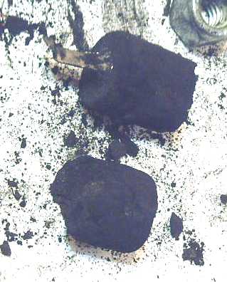 Third try: Getting better! But it
broke apart
where the folded current collector strip ended.
Third try: Getting better! But it
broke apart
where the folded current collector strip ended.
Resistances from any point to another on the broken end of this were
around 30 ohms.
The fourth or fifth try looked
usable. The
crumpled current collector is at the outside
at both ends, and a clump of material broke off at the top, exposing
the top fold.
(It looks like more might want to break off the side.)
For some reason resistances this time seemed to be in the hundreds of
ohms, but it varied a lot.
From some points to the current collector it measured only around 60-80
ohms.
But I didn't want to break it by pressing very hard with the meter
probes.
It weighed 12.2 grams after drying. (Current collector is about .8
grams of that.)
Jose's
nickel-iron
cell
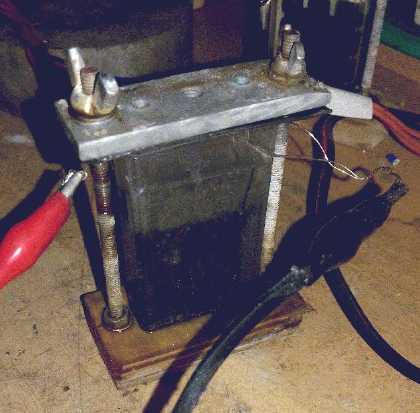 [30th] Jose sent me some info on the Ni-Fe
battery he had successfully made and his techniques. Now he was going
to try manganese zinc with zinc sulfate electrolyte.
[30th] Jose sent me some info on the Ni-Fe
battery he had successfully made and his techniques. Now he was going
to try manganese zinc with zinc sulfate electrolyte.
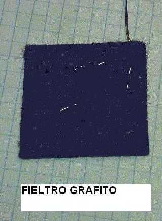 He had made
some nickel foam and graphite foam flat electrodes, and was planning
zinc in graphite foam. He threaded a nickel wire into the foam to get
good connection, and then, depending on what the active material was,
used sintering or electro deposition to impregnate it. He mentioned
zinc.
He had made
some nickel foam and graphite foam flat electrodes, and was planning
zinc in graphite foam. He threaded a nickel wire into the foam to get
good connection, and then, depending on what the active material was,
used sintering or electro deposition to impregnate it. He mentioned
zinc.
 That reminded me of my graphite
felt - very similar. What about wrapping a piece of that around the
inside of the can and electroplating it? The felt would be bound to
contact the can in spots, and once some zinc plated it the connection
should be secure. That might work better, maybe much better, than the
things I had tried so far. And the felt (or foam) has oodles of surface
area compared to flat copper. I ripped a piece into two halves but it
was still so thick it seemed I would need a bigger diameter of copper
pipe for the can - 1 inch instead of 3/4. Well, that's about "C" size,
which is what I was planning on making if I could draw out the cans I
wanted from a single piece of copper. (A smaller center electrode would
work instead, but then the proportions between the two electrodes would
surely be way off.)
That reminded me of my graphite
felt - very similar. What about wrapping a piece of that around the
inside of the can and electroplating it? The felt would be bound to
contact the can in spots, and once some zinc plated it the connection
should be secure. That might work better, maybe much better, than the
things I had tried so far. And the felt (or foam) has oodles of surface
area compared to flat copper. I ripped a piece into two halves but it
was still so thick it seemed I would need a bigger diameter of copper
pipe for the can - 1 inch instead of 3/4. Well, that's about "C" size,
which is what I was planning on making if I could draw out the cans I
wanted from a single piece of copper. (A smaller center electrode would
work instead, but then the proportions between the two electrodes would
surely be way off.)
Image: Cans. Sub-C with too much thickness of felt and one
close to "C" just made April 2nd. (Filled with water to test for leaks.)
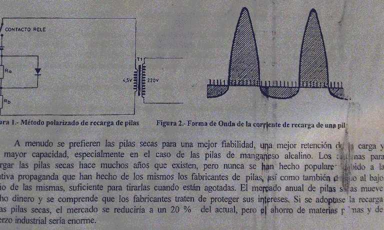 Another idea Jose sent in a picture was an odd form of "pulse charging"
to recharge alkaline manganese-zinc cells. Using a diode drop, the
charge current goes slightly negative for half the line frequency
cycle. Apparently they charge better and last more cycles. Perhaps it
helps reduce dendrite formation? (The edges of the picture were already
cut off. I did cut off the top half, which listed the problems of
nickel-cadmium cells and hence why recharging manganese-zinc cells
would be better if it can be made to work well.)
Another idea Jose sent in a picture was an odd form of "pulse charging"
to recharge alkaline manganese-zinc cells. Using a diode drop, the
charge current goes slightly negative for half the line frequency
cycle. Apparently they charge better and last more cycles. Perhaps it
helps reduce dendrite formation? (The edges of the picture were already
cut off. I did cut off the top half, which listed the problems of
nickel-cadmium cells and hence why recharging manganese-zinc cells
would be better if it can be made to work well.)
(It also says [not that I can read Spanish without looking
up half the words] at the bottom that if Mn-Zn cells were
rechargeable the market would drop to 20% of what it is. But it seems
to me that
if they were really long lasting, usage would surely shoot way up: They
would provide for economical solar, EV and even power grid energy
storage. It would surely absorb all the production capacity for some
years if not overwhelm it.)
Drawing Copper Cans?
I'm not 100% sure why I would want think about this
without
having succeeded with the silver soldered "sub-C" cells yet. But I have
this
vision of the perfect copper "C" cell can and it seems like a cool
project. If I'm having trouble with the zinc plating, at least it's
another direction where I can probably forge ahead solving problems
that are well known in ways that have been done by others before.
I kept looking at a 2013 video from "NYC-CNC" about
drawing cans [for bullet jackets] that somehow seemed better/easier
than others.
Drawing Copper / Making punches & dies - Video
https://www.youtube.com/watch?v=M10Z-1ZStdo
It showed the 2nd
and 3rd draws that made a shallow can into a tall thin one. The
"bushing" and "die" of both punch and die sets fit into the same
outer sleeve that holds them "perfectly" aligned. The "punch" fits
exactly into the hole going through the bushing, and the shallow cup
from the first stage fits into the widened bottom of the hole. After
putting it into the sleeve with the die beneath, pressing on the punch
pushes the workpiece into the die, straight and centered. It comes out
longer and with thinner walls. The third set is the same as the second
but makes it still longer and thinner, with still thinner walls.
A couple of the commenters underneath the video had good
ideas for
small improvements. One I thought might be good would be to make the
second punch end with a 45° (?or other angle? ?Also the first
punch?) taper such that its square bottom diameter was the same
diameter as the next punch's outer diameter, to help keep the next
punch centered. (Then again, would that punch itself work as well that
way? I don't see why not.)
I thought it might be most practical to do that in about a
"C" cell size. That size may not be very common any more, but it seemed
to me it would be about the easiest and most practical for me to do.
For the amount of work they're likely to be in prototyping or limited
production, "AAA" or "AA" would be frustratingly little cell for the
effort plus a very long "draw" that would probably need an annealing
step, while "D" would make for a very fat center electrode with lower
current capacity. (Ignoring the problems with making them including
drawing the can, a double length "C" cell should have about the same
storage capacity as a "D" cell and substantially higher current
capacity.)
I measured a "C" cell, a Ni-MH picked up
from a recycling bin. It
was 25mm OD and counting the button, 50mm long. Or if you prefer, 1" OD
x 2" long. (The actual body length was 47mm.)
Maybe I'll look up his earlier video about making the
first punch and die and try that first. If I can form the shallow cups
okay, I'll do the second set, and if that's still a success, the third
and last.
I remind myself that my cans will be a lot bigger than
his, and so they probably will be more exacting to do and obviously
will need my
heavy hydraulic press.
[10th] I guestimate that the initial size of copper disk to end up with
a C-cell size can would be around 48mm of . Rather than create a punch
to make them - especially as that might not be optimum - I'll cut the
initial disk out with tinsnips. That'll be one simplification to help
get things going.
I went to the refuse station to discard something and
hunted around the piles of metal. (What a blessing that the attendant
is for attempts to reuse discarded materials and items instead
of telling people to stay away, as if the trash was valuable instead
of people occasionally relieving the system of a few of the things it
has to deal with! "Just be careful - and don't sue us if you hurt
yourself!")
I found an outer sleeve piece, and a heavy "cylinder"
piece that almost fit right into it for one die. If I expand its inner
hole to about 1.3" and cut off a 1.25" bolt to the smooth shank, I
might have the makings of the first (or second?) punch and die. Maybe
I'll try a 1.125" bolt size first and see if the disk can be squeezed
through. One can always make the hole bigger, but not smaller. (The
hole is for a 1" threaded bolt. I can't use it for the final 25mm/1"
C-cell diameter unless a 1.0"(?) hole eliminates the threads and leaves
smooth sides.)
[11th] I spent much of the afternoon watching NYC-CNC videos about
making drawing dies. He had a 9 part series. It was a little before the
one above with the two punch and die sets that fit in the same outer
sleeve (all in 2013), but I got a few good tips and ideas. I also
thought of "weld-on hubs" usually used for chain sprocket hubs, which
might make nice ready made bushings. I had some, 7/8", 1.0" and 1.125",
and pieces of shafts from my motors in 7/8" and 1.0", with another I
could turn down to 1.125".
I started to think about the copper, too. The 3/4" copper
pipe measured about 1.1mm or .040" thick. I thought that was much
thicker than necessary. But how thick would be good? .020"? .015"? I
went out to the garage at 1 AM with a caliper and just felt the copper
sheets. .020" did seem like a good thickness. It had considerable
stiffness, although not utter rigidity. Or .025" would be okay too - a
little stiffer than .020". .010" seemed a rather flimsy and I didn't
run across any .015". I decided to try for .025" or .635mm.
NYC-CNC was using .030" stock. My piece was a lot bigger,
so even if I wanted the same wall thickness, I should start with
thicker copper. I found my thickest copper sheet metal. The caliper
said 1.7mm or .067". Just over double. If one assumed the base would be
the same thickness as the side walls, one should be able to calculate
the wall thickness that would result from a given size piece of copper
when transformed from a flat sheet/plate to a can 25mm diameter by 48mm
long.
If I cut a 50mm disk, π*25^2=1963.5 sq.mm. 1963.5 * 1.7mm
thick = 3338cmm (3.338cc / 3.338ccm).
Next, a 25mm OD * 48mm pipe circumference is 25*π * 48 = 3770 sq.mm
And the end disk 25^2*π/4 = 491 sq.mm
3770 + 491 = 4261 sq.mm
The volume of the copper will remain the same however it is deformed,
3338cmm. Spread over 4261, that would be:
3338/4261 = .78mm thickness (.031"). Apparently I should try a smaller
initial disk to start with.
A 48mm disk would be: 24^2*π * 1.7mm = 3076cmm.
3076/4261=.72mm thickness. That's about .028".
A 46mm disk would be: 23^2*π * 1.7mm = 2704cmm.
2825/4261=.663mm thickness. That's about .026". I think that should be
fine. A little extra sturdiness can't hurt.
A 44mm disk would be: 22^2*π * 1.7mm = 2704cmm.
2585/4261=.606mm thickness. That's about .024".
So the 3/4" plumbing pipe is .040" and I'm shooting for
.026"? Hmm, that's not a whole lot thinner. I was thinking the
pipe was
grossly thick compared to requirements, but it looks like it's
just a little overkill.
The 28 gram "sub-C" cell can would drop from ~28g to ~18. Am I wasting
my time? But the other difference is that the 3/4" pipe
(~7/8" on the outside) makes "sub-C" cell diameter, while swaging my
own I would make "C". Either of those seem like convenient sizes, where
"AA" might be frustratingly small for me to work with and not much cell
for all the efforts that go into one, and "D" would make for a very
thick center electrode (and I would have to find another pipe size to
compact that size.) But the volume of "C" would be 25^2*π/4 * 47 = 23cc
compared to
22^2*π * 42 = 16cc for "sub-C", almost 50% larger. (Reading specs some
"Sub-C"s say 3 amp-hours while "C" is 5.) That seems like a
good increase for what should be about the same amount of work. (And
using graphite felt to make a thick zinc electrode it would seem going
to "C" is necessary to fit everything nicely.)
http://www.TurquoiseEnergy.com
Haida Gwaii, BC Canada