Turquoise Energy News #157
covering June
2021 (Posted July 7th 2021)
Lawnhill BC Canada - by Craig Carmichael
www.TurquoiseEnergy.com
= www.ElectricCaik.com
= www.ElectricHubcap.com
Month
In
"Brief"
(Project Summaries etc.)
- Ultra Efficient Chevy Sprint Revival: Direct Drive to CV
Shaft With 96%
Efficient Reduction Gear - New Motor design - "Plug & Play?" DC
Power Components
In
Passing
(Miscellaneous topics, editorial comments & opinionated rants)
- Public Committees - Small
Thots - ESD
- Detailed
Project Reports
-
Electric
Transport - Electric Hubcap Motor Systems
* Making & Driving 96% Efficient Direct "Motor to Planetary
Reduction to CV Shaft Drive"
for
Chevy Sprint: - Coupling the components - Mounting them - Torque
improvement - Driving (on acreage only) - Conclusions
* Designing "car drive size", unipolar, outrunner, BLDC, "Electric
Hubcap" type motor
Other "Green"
& Electric Equipment Projects
* Off grid infrastructure: "Plug-and-Play Solar"
* Greenhouse, Gardening
* Innovative Beekeeping for the BC Coast
Electricity Generation
* My Solar Power System: - Daily/Monthly
Solar Production log et cetera - Monthly Summaries and
Estimates (27 months)
Electricity Storage
* Turquoise Battery Project
(NiMnOx-Zn in Mixed Alkali-Salt electrolyte) (No
Report)
This month I did a notable electric transport project:
an "ultra-efficient" fixed reduction electric car drive train (below
& in Electric Transport). Also surely worthy of note in In
Passing is the idea of volunteer "Public Committees" to advise
elected government on best directions for society in any and every
field, and in any and every issue that arises within that field. It's
an idea mentioned before, but I think put more understandably herein.
Last month with one thing and another I didn't finsh TE
News
#156 until the 9th.
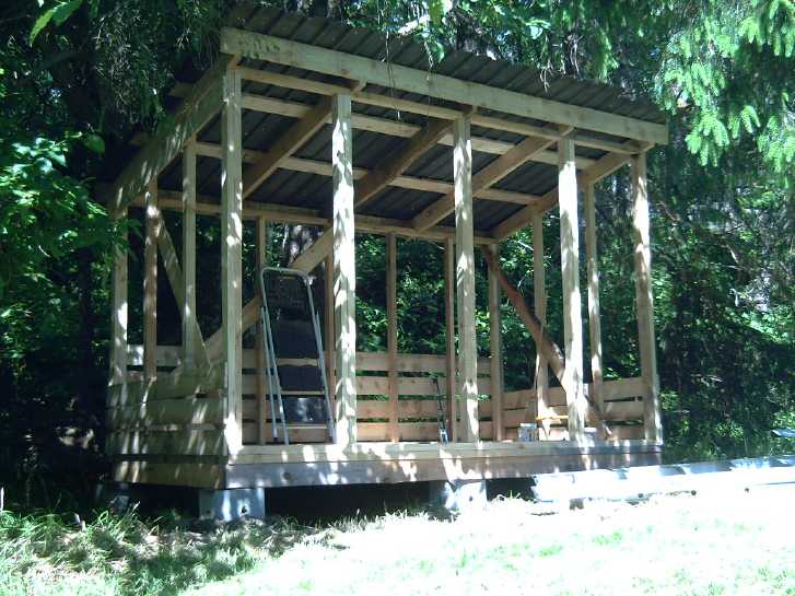
I hoped to do better this month by doing much
editing before the the next month started, but there were many
distractions and with firewood on order I really needed to make a
second firewood shed. With just one shed, even if it's big enough to
hold all the firewood you need, you inevitably end up stacking fresh,
green firewood in front of the remaining seasoned firewood. Even this
second one will be split into two smaller ones side by side to make it
easier to stack fresh wood in a vacant space. I had the floor done by
the 26th and started putting up the walls.
 I
finished my
"Bee Barn" on the night of the 8th and
set
it outside the next morning. (to get it out of the workshop!) I made
special frames edges into which one would slide the "nuc" frames with
the new bees, brood and honey into, making them into tall frames for
the tall space. The last feature was a little roof over the entrance so
the bees would stop getting wet in damp weather even before they
alighted instead of entering the hive.
(But still no bees! Looks like it'll be next year now. I put a plastic
"tarp" over it.)
I
finished my
"Bee Barn" on the night of the 8th and
set
it outside the next morning. (to get it out of the workshop!) I made
special frames edges into which one would slide the "nuc" frames with
the new bees, brood and honey into, making them into tall frames for
the tall space. The last feature was a little roof over the entrance so
the bees would stop getting wet in damp weather even before they
alighted instead of entering the hive.
(But still no bees! Looks like it'll be next year now. I put a plastic
"tarp" over it.)
After I made it, I mentioned it to Al, and he directed me
to a website called "ApiHex.ca" where they already make plastic well
insulated beehives. If I had known, I'd probably have bought one.
It had some great features, seemingly well thought out. The two things
it didn't have were that it took standard Langstroth frames rather than
"bee barn" tall ones, and it didn't have a roof over the entry. I could
no doubt have hacked it to meet my specifications more easily than
building from scratch if I had known about it, but what I've built is
just as good if not as "stylish". Bees won't care.
Chevy Sprint Revival: 96% Efficient
Direct Drive to a CV Shaft Via
Reduction Gear
With the schedule more or less cleared for a moment and
the Yun Duan 5:1
planetary gearset ordered through AliExpress.com having at last
arrived, I was eager to
start
on the Sprint and see what the performance would be like. Somehow it
didn't
matter that it wasn't a special sort of groundbreaking project or even
original, or that I had
many better, more urgent or more important things to do. Or that it was
really just an experimental demo of an ultra-efficient drivetrain and
wouldn't, even working well, replace the Nissan Leaf.
The 96+% efficient, 5 to 1 reduction planetary gearbox,
coupled directly to the car's right side CV drive shaft, are the only
components between the motor and the wheel - ie, there are almost no
losses. If a typical vehicle transmission is only 60-70% efficient as
I've always heard (with driving the differential gears to the wheels
presumably imposing a further penalty), this means perhaps a 50%
efficiency boost over a "typical" car conversion to EV, which almost
invariably seems to use the original transmission and differential.
Thus the motor can be 2/3 the size to provide the same performance, and
the batteries will take the car 50% farther.
 So at the expense of other things, I spent most of my
available time for two weeks on it, and then did a few "finishing
touches"
here and there over the next days. For once a project didn't stretch
out
interminably into the future. The motor controller was already in the
car, and all that was needed was to mount the motor and gearbox... and
put in some batteries, of which I didn't have quite enough for
everything any more.
So at the expense of other things, I spent most of my
available time for two weeks on it, and then did a few "finishing
touches"
here and there over the next days. For once a project didn't stretch
out
interminably into the future. The motor controller was already in the
car, and all that was needed was to mount the motor and gearbox... and
put in some batteries, of which I didn't have quite enough for
everything any more.
I had the drive assembly mounted in the car in
a week. I hooked up a battery to the motor and ran some quick tests. It
appeared to have more torque than in the previous incarnation with the
original transmission. This seemed remarkable as the reduction ratio
had gone from 8.9 to 1, down to 5 to 1. More torque in a "higher gear"
instead of less? But actual driving showed that the quick tests without
actual figures must have been deceptive. It was no doubt better than 5
to 1 with the old transmission (and with the differential) would have
been, but it wasn't "twice as good".
As a rough estimate, the
car with the drive system and
batteries under the hood probably weighs only about 1570 pounds plus
the driver. (Empty Car 1400 [est], Motor 51, Gearbox 15, Batteries
about 100 pounds, misc.) The motor
controller was still mounted on the center hump behind the firewall
between the driver and passenger. Everything else to do with the
compact drive fit under the hood, including two 36 volt stacks of
lithium-ion batteries providing 36V, 240AH or 8640WH. So the entire car
was free for its original uses. One could of course fill the spare tire
space and part of the cargo space with more batteries to give it very
substantial driving range.
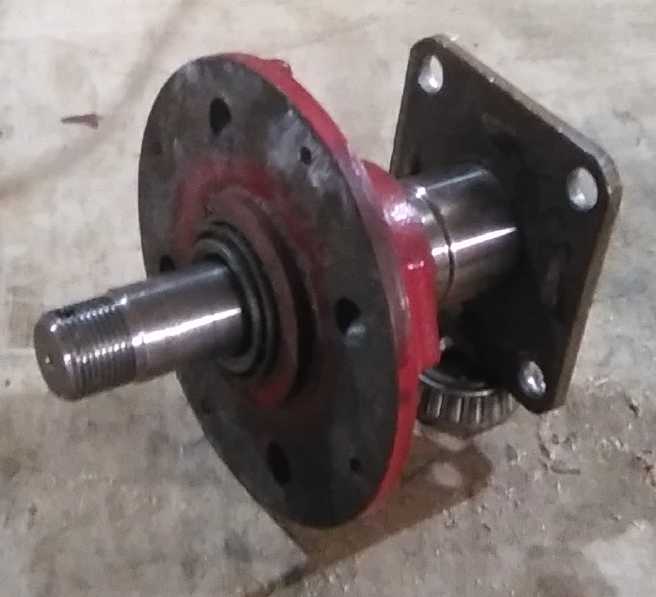
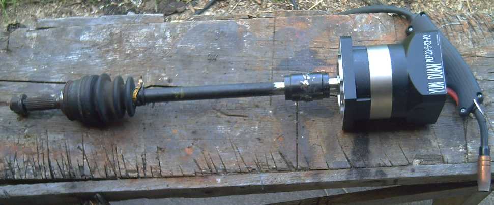
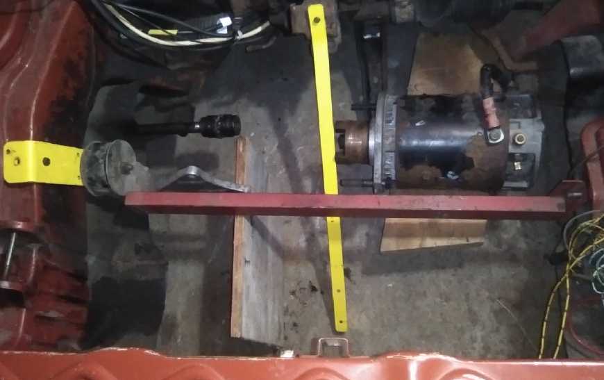
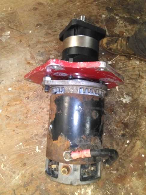
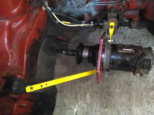
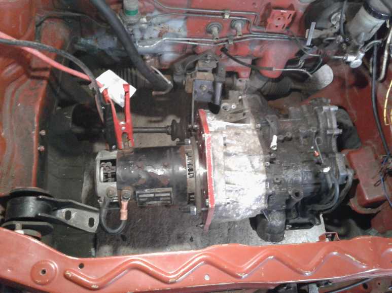
 Rear/Top: Forklift motor to 96%
efficient
planetary gear reducer to starboard side CV shaft.
Rear/Top: Forklift motor to 96%
efficient
planetary gear reducer to starboard side CV shaft.
Red rectangular steel tube running diagonally from below Motor to
Frame higher up
replaced previous "flimsy" yellow bar to hold drive assembly against
high torque loads.
(had to cut into 3/4" plywood battery shelf to fit it.)
There's also a 1/4" plywood front wall. Can't accidently short
batteries to wood, keeps out flying debris!
Ctr: 500 amp fuse in holder, mounted on top of a piece of 2"x6" to
raise it near to "+" at top of batteries
Right (port): 2 stack assemblies of 10 "LG" li-ion batteries, total 240
AH, 36 V
Left (stbd): Green 12 V, 40 AH li-FePO battery for car electrical,
stereo. (Car plugs in to battery!)
Yellow cord: Charging car from 36V DC solar system; panels on house
roof.
Illegible here, meters show voltages, current and total energy of
charging.
What was to be determined with this experimental project:
* With the high efficiency, would a mere 5 to 1 ratio gear be enough
speed
reduction to give the car sufficient torque for decent acceleration
from a stop and for climbing hills?
* How would driving a single wheel perform? Would it pull to one side?
Would it slip?
* How fast would the car go on level road? (This could be estimated in
advance from the difference in ratios from the 2018 trials with the
"cludged" original transmission: 8.9/5 * 25 KmPH = 44.5 KmPH. Since it
doesn't have a speedometer and hasn't been on the road so far, we'll
just estimate "45 KmPH".)
On the summer
solstice I drove the car across the acreage... and got it stuck there.
One of my motor supports was too flimsy and bent - almost folded -
under high torque. (Oops, no picture!) And the coupler to the CV shaft
started slipping. I fixed these problems that day and the
next. Luckily the weather was finally nice for a change.
 When I got to the base of the hill rising to the main
driveway I stopped. (mistake! Here I must note that the car still
doesn't
back up except by pushing it, or by rewiring the motor to change the
direction, and then again to go forward again.) The car didn't make it
up the hill. It was going very slowly when the
new supposedly 300 amp circuit breaker (more like 100!) blew 3/4 of the
way up. When I tried
to start on the hill, with the added weight (motor, batteries, driver)
nearly all
on the left and the lightweight car also leaning to the left on the
hill, the drive
wheel - the right front - slipped on the grass. I shoveled in a little
pea gravel,
When I got to the base of the hill rising to the main
driveway I stopped. (mistake! Here I must note that the car still
doesn't
back up except by pushing it, or by rewiring the motor to change the
direction, and then again to go forward again.) The car didn't make it
up the hill. It was going very slowly when the
new supposedly 300 amp circuit breaker (more like 100!) blew 3/4 of the
way up. When I tried
to start on the hill, with the added weight (motor, batteries, driver)
nearly all
on the left and the lightweight car also leaning to the left on the
hill, the drive
wheel - the right front - slipped on the grass. I shoveled in a little
pea gravel,
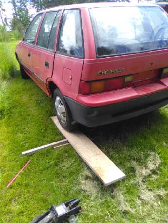 and finally put a ramp
under the left rear wheel so one wheel was going downhill. I thought
that would get it going, but I had to repeat it. It didn't get up any
speed
and it kept slipping whenever it reached the end of the pea gravel. And
finally there was a last little dip where the wheel would neither slip
nor rise out of. It was stalled. 5 to 1 just was close to but not
quite enough reduction to give satisfactory hill climbing torque with
this motor and controller.
and finally put a ramp
under the left rear wheel so one wheel was going downhill. I thought
that would get it going, but I had to repeat it. It didn't get up any
speed
and it kept slipping whenever it reached the end of the pea gravel. And
finally there was a last little dip where the wheel would neither slip
nor rise out of. It was stalled. 5 to 1 just was close to but not
quite enough reduction to give satisfactory hill climbing torque with
this motor and controller.
I drove it around on the more level driveway area, but it
still slipped pretty easily on the grass going uphill. Other than that
it seemed to
have enough pickup and drove quite nicely. It didn't pull to one side
when I "booted" it that I could notice. But then it wasn't a very
powerful "boot". I didn't take it out on the road because I doubt that
it
would make it back up my longer steep driveway into the yard at the end
of the trip. (Rats!)
I put the old 135 amp breaker back in and had no further
trippings. From then on I always took a run at the hill and always made
it up - by early July, numerous times including with loads of lumber.
Even with 96% drivetrain efficiency, one can only push a
motor so far. With this motor, 7 to 1 instead of 5 to 1 probably would
have
climbed hills from a stop fine even with 'potholes' - wheel slipping
aside. It would also limit the potential speed to 32KmPH instead of 45.
I didn't get to see how it would go on level pavement, but I think it
would have gone a long way per unit of energy consumed, even if not
very fast.
And I concluded (no surprise!) that a single
wheel drive really isn't for "off road"!
A motor with more torque
and a higher maximum RPM should
put the car on city streets. It would have to be 4500 RPM for 90 KmPH
on the highway.
My thought is that I should try and make the long planned
"Electric Hubcap unipolar outrunner" BLDC motor. It would probably meet
the torque requirements and have RPM at least for 60 KmPH (3000 RPM).
If I do of course it'll be ultra efficient throughout and use the least
electricity in any situation.
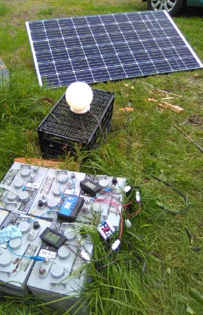
On the 23rd, I made up some plugs and cables, and connected every
second cell between the two parallel batteries for the balance
charging, and started charging the Sprint - which now had both of my
assembled 36 volt
lithium ion battery stacks in it - from the DC solar power system, for
which the equipment is already in the garage and the panels on the
house roof. Thus my recorded solar DC
power figures jumped up this month from almost 0, and the 13th solar
panel was being used a bit more than trivially. (If I could drive on
the
highway and really work the batteries it would be much higher!)
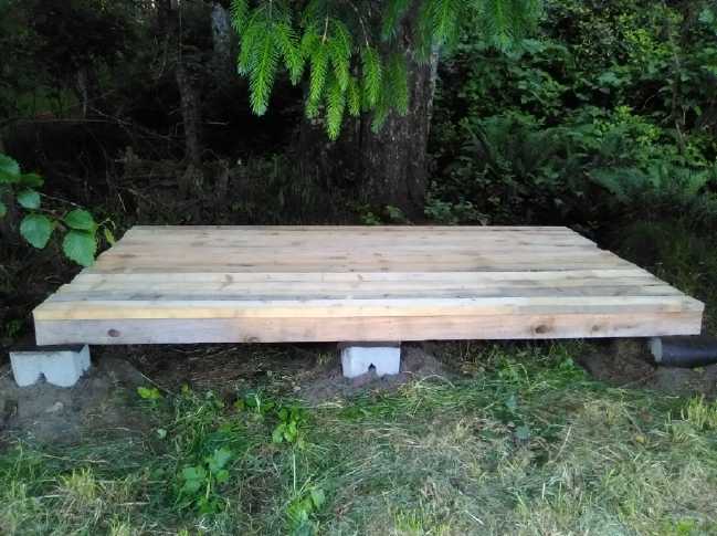
Firewood Shed July 5th. 100% my
own cut lumber.
Roof of scrap sheet metal with old screw holes caulked.
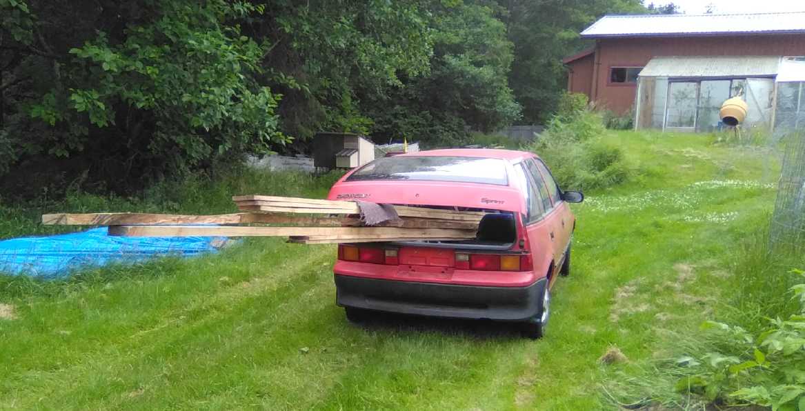
 By the 26th,
if I couldn't use it on the highway, I found
I could at least use it for hauling lumber from the piles where I had
stacked the wood I cut with the handheld bandsaw mill over the last 3
years, to the shop to it cut up for the new firewood shed. It actually
saved me considerable heavy hauling by hand.
By the 26th,
if I couldn't use it on the highway, I found
I could at least use it for hauling lumber from the piles where I had
stacked the wood I cut with the handheld bandsaw mill over the last 3
years, to the shop to it cut up for the new firewood shed. It actually
saved me considerable heavy hauling by hand.
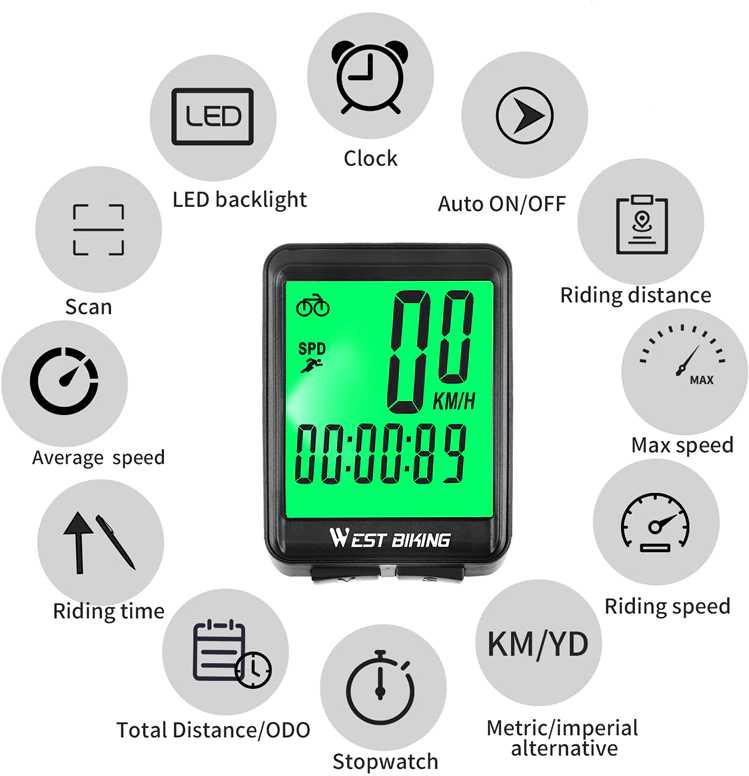 A problem with not using the original transmission was that there was
no way to hook up the speedometer/odometer. I ended up ordering a
bicycle speedometer, which comes with all the required parts. A magnet
"in the spokes" (or on the shaft) triggers a sensor that counts wheel
revs. The wheel diameter is a programmable numeric setting, which gives
it the flexibility to use with the car, presumably up to 99.9 KmPH.
A problem with not using the original transmission was that there was
no way to hook up the speedometer/odometer. I ended up ordering a
bicycle speedometer, which comes with all the required parts. A magnet
"in the spokes" (or on the shaft) triggers a sensor that counts wheel
revs. The wheel diameter is a programmable numeric setting, which gives
it the flexibility to use with the car, presumably up to 99.9 KmPH.
I may yet take the car out on the road for a few tests
once I can measure speed and distance. (Even if I have to tow it back
up to the top of my steep driveway on the return!)
Outrunner "Electric Hubcap" Motor
Layout?
 Thinking about making that new type of motor, I did a bit of figuring
and checking. It looked like a trailer stub axle and machined-down hub,
which I had made a couple of in my earliest motor experiments, could
make a great center for such a motor.
Thinking about making that new type of motor, I did a bit of figuring
and checking. It looked like a trailer stub axle and machined-down hub,
which I had made a couple of in my earliest motor experiments, could
make a great center for such a motor.
 And I spaced out some of my my "standard" independent-mount motor coils
with iron powder centers and ilmenite magnetic circuits around a 300mm
rotor and found that that seemed like just about the right diameter for
the outside of the stator.
And I spaced out some of my my "standard" independent-mount motor coils
with iron powder centers and ilmenite magnetic circuits around a 300mm
rotor and found that that seemed like just about the right diameter for
the outside of the stator.
Adding the "outrunner" rotor would make the outer diameter
just over 360mm. With the flux gap at about 156mm radius, and with 12
coils and 16 supermagnets (2"x1"x.5" or 2"x1"x.375"), the potential
torque for this layout of motor should be quite high - I expect
substantially higher than the forklift motor.
[a few more details in detailed report] Now, about when
I'll be able to get to it...?
"Plug & Play?" DC Power Components
 I
started making good use of my DC "T-Plug" plugs, sockets, and power
monitors to see if the remaining golf cart batteries from the truck
would come back to life. I connected a 305W solar panel through a power
monitor, a DC to DC converter, another power monitor and a PWM lead
acid battery solar charge controller to two (6V) batteries in series at
a time.
I
started making good use of my DC "T-Plug" plugs, sockets, and power
monitors to see if the remaining golf cart batteries from the truck
would come back to life. I connected a 305W solar panel through a power
monitor, a DC to DC converter, another power monitor and a PWM lead
acid battery solar charge controller to two (6V) batteries in series at
a time.
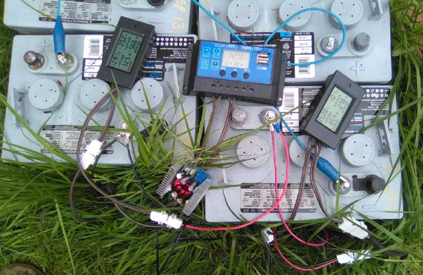 I could see
the solar voltage and current, the DC to DC converter output voltage
and current, and the battery voltage via the charge controller.
I could see
the solar voltage and current, the DC to DC converter output voltage
and current, and the battery voltage via the charge controller.
With this setup I determined that the idea of using the DC
to DC converter in the charging circuit to reduce the 30+ volts solar
panel to 17 volts instead of using a 17 volt one doesn't work properly.
As long as the panel could supply whatever current the DC
to DC converter was set to, everything was fine. One would see (eg)
36V, 1A on the high voltage side and after the converter to the
batteries, 13.3V, 2.5A.
But as soon as there wasn't enough light, the converter
would "short" the solar panel down to the low voltage level, and so the
current to the batteries would drop to (eg) the 1A figure.
Owing to this wasting of low sunlight, one would set the
converter's current limit to a lower current than could be supplied by
bright sunlight, wasting the highest energies as well.
Apparently the charge controller can't figure out that if
it backs off its demand a bit, it gets way more current. Presumably an
MPPT charge controller would do better... but if it's really an MPPT
controller, one can simply feed the higher voltage solar panel straight
to it. But the pulse charging from PWM controllers makes lead-acid
batteries last longer.
In
Passing
(Miscellaneous topics, editorial comments & opinionated rants)
Public
Committees
I had been seeing the works of Daniel Raphael on "Social
Sustainability Design Teams" and "Third Stage Democracy" and I was sure
he was onto something special, but I was also sure that the name he had
given the former didn't make
it an easy "sell". To me it conjured up virtually no picture
of what it was all about. I had been trying to come up with some
better name for quite a long time without thinking of anything
promising.
On the 12th I woke up in the morning with the term "Public
Committee" floating ever so faintly in my head. What was that? Random
words drifting through my mind? But when I brought this shadow
of an echo of a thought to consciousness, I immediately realized it was
the name I had been searching for, yet totally unlike anything I had
come up with. My thanks to my angels, the indwelling spark of the
Universal Father, the cosmic mind or whoever it
was!
The name "Public" implies of course that the public is
involved. Of, for and by "the people"! The name "Committee" immediately
gives a sense of what it is:
a small, perhaps temporary, internally organized group with a defined
hierarchy and positions, brought into existence to study or focus on a
specific issue or topic. Thus the intent is readily understood.
Every detail of the organization might be just as Raphael has defined
it, but a committee is exactly what it is. What do governments set up
to study an issue and make recommendations? What do they listen to (or
ignore)
besides the mega-corporations whining loudly in their ears? Committees!
A
public committee thus becomes a volunteer extension of the government.
"Off the cuff" hypothetical examples:
Public Committee on Dairy Product Production and Distribution
Public committee for New Parent Education
Public Committee Concerning Private Residential Property Rights
and Responsibilities
Public Committee on Bylaw Interpretation and Application
Public Committee on Provincial Electoral Procedures
Public committee on Public Educational Goals
and so on and so on and so on. Many of these would probably have a
place name
in front of them, so "Victoria Public Committee on Sewage Treatment and
Nutrient Recycling"
might determine better solutions for that particular city, which is
surrounded on three sides by sea.
I hope this shows with the variety of examples that all
sorts of
social and societal issues might be - and eventually will be - the
focus of attention with the intent of improving on present day
practices. Once the idea takes hold, it should spread exponentially.
The first ones that are formed will probably have the greatest impact
and stir the most excitement, but in the aggregate they will soon
(decades) utterly transform human civilization - doubtless for the
better in every area.
And many such local committees would
connect together on the internet to discuss issues to be presented to
larger governments than local. Again, as elected officials
who represent the public realize that submissions and reports from such
groups represent the
thinking and wishes of the more intelligent, more thoughtful segments
of society who are the most involved with the issue they are
presenting, they will realize it is their place to give them
legislative or other governance effect. Representative government will
therefore continue, but it will become much more representative of the
public will, and it will start to attract a different sort of people
and become more of a coordinative function.
Thus the combined talent and creative thought of all,
instead of that of just a few elected to positions of representation of
all, will go toward improving the human condition. This will create a
new age, a new chapter in the history of human evolution, the journey
toward Light and Life, toward Utopia, or whatever one terms it.
Note: Presently and for some time, the term "committee" has had
something of a "bad rap".
Something poorly thought out with dubiously useful or even conflicting
components is sometimes said to have been "designed by a committee" -
everything a compromise overall perhaps satisfying to no one.
(The very spelling of the word "committee", versus something like, say,
"commity" seems to have been formulated to be as awkward as possible.)
Most
committees visible to the public are put together for political
purposes and they may come to conclusions not always agreeable to the
public. More often, they seem to come to good conclusions, which are
then usually
ignored by the government in full session for political reasons.
However, any committee does put together several minds in
an organized manner to focus on something specific, and the coordinated
creative thoughts of multiple
people can multiply together rather than just add, especially if the
structure lends itself to it. Raphael seems to have put much thought
into the structure of the "Public Committee" idea that he calls the
"Social Sustainability Design Team". And a Public Committee is likely
to generate ideas and plans agreeable to the general public, on many
topics of interest to various groups, and in the long term best
interests of society. A "committee of public committees" communicating
over
the internet on a regional, national or global level, is likely to come
up with the best solutions presently thought of by anyone and
acceptable to many, in their area of study.
And when those solutions have had their day and are
becoming obsolete, whether 1, 10 or 100 years later, when they are no
longer enhancing the universal core values of being human, members of
the public will recognize the disharmony and
organize new committees to update solutions and keep them current.
Updating of obsolete solutions is a rare occurrence today, and no such
organized planning groups except as affiliated with special interest
groups, exist
today.
Gardening
Plantings
It being the end of spring and
finally some good weather toward the end of June, I filled in the
garden with what few seedlings I had started and
whatever else I could come up with. Somehow I have 5 potato patches. If
a crop that feeds many people is going to grow like weeds, why argue?
Wherever I threw sods of grass to get rid of them, I also threw in a
few potatoes. They outgrow everything else.
Free Wheat - Chicken Feed
Near where I have the chicken pen, I hadn't mowed the lawn
because it was panicing the chickens. The grass and ferns were tall and
lush. As I pulled some out to give the chickens some greens, I realized
some of it was wheat. It was already forming heads bigger than grass
seeds. Huh? Hmm... I was feeding the chickens sprouted wheat. They're
messy eaters. The chicken pen is semi-portable and I shift it over to
fresh lawn now and then, and to let the previous section recover. The
wheat was growing where it had been in the spring.
If the lawn was growing wheat instead of just grass, it
would be free chicken feed. Inspired, I took the chickens' next meal
(sprouted kamut) and sprinkled it around where the pen had more
recently been and the grass was still short, then watered it. July 5th
is a rather late start, but perhaps there'll be grain there come
autumn? (The next day, two chickens got out somewhere and were eating
it!)
Slugs & Sawdust
Having good fences to keep the deer out,
slugs are the number one concern. It's disheartening to have a row of
beans, chard, quinoa or something and come back and find a couple of
plants savaged, and a couple of days later a few more, until you
finally realize they're all gone.
 Zucchini transplanted into ground
and just
about to take
Zucchini transplanted into ground
and just
about to take
off, when its first real leaf was bit off at the stem by a slug.
By the time it recovered and started some new
leaves, others started later were much larger.

Someone said broken oyster shells would keep them out.
Then someone else said clam shells or egg shells were just as good. I
put some clam shells around some quinoa, but I suspected it was just a
rural myth. Or rather that one needed a wide layer of them. Gardeners I
asked about slug control kind of rolled their eyes. They had ideas and
things they did, but no magic bullet.
Then I came up with the idea of sprinkling sawdust around.
That seemed to work quite well in many places. (It's spruce sawdust,
since that's what I'm cutting. I don't know if the type is important.)
The weather being cold, windy and wet when I transplanted
them out, I also put up some boards as wind guards.
After the sawdust the slugs seemed to leave the quinoa
alone and it was growing well by July 4th (below).

 I did space
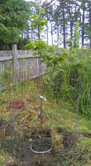
out on one fence... Since my apple trees bloomed at different times
there was no cross pollination and so no apples. So finally I bought a
third one. When I planted it, I did everything else "by the book". I
looked at it the next day and a deer had eaten all the foliage except
near the top. (I saw there was one still for sale outside the store,
and a deer had got at that one too.)
I did space
out on one fence... Since my apple trees bloomed at different times
there was no cross pollination and so no apples. So finally I bought a
third one. When I planted it, I did everything else "by the book". I
looked at it the next day and a deer had eaten all the foliage except
near the top. (I saw there was one still for sale outside the store,
and a deer had got at that one too.)
 The small corn plot in the
greenhouse seemed to
be growing nicely by July 4th.
The small corn plot in the
greenhouse seemed to
be growing nicely by July 4th.
(The broccoli (left) is growing heads - and shading other things out,
so I'm plucking
them out to make room. The chickens love the leaves from any cabbage
family plant.)
Small
Thots
* We Canadians pay high rates for our
telecomm services, and the government seems to abet overcharging and
makes regulations designed to stifle competition. Recently the Trudeau
government appointed "ex" executive Ian Scott from Telus, just one of
the telecomm companies with a corporate culture of greed,
misrepresentation and fraud, as the head of the Canadian Radio and
Television Commission (CRTC), the watchdog agency regulating such
industries. This, like the USA's "revolving door" of high personnel
between the federal government and the big banks, is a clear conflict
of interest, a betrayal of public trust by our government as they put
the wolf in charge of tending the sheep. No doubt the telecomm
companies have used some of their excessive profits - our money - to
induce the government to make this appointment.
To cement his reputation as inappropriately representing
the interests of the "big telecomm" rather than those of the public
entailed in his position, someone recently snapped a photo of him in a
bar having a private beer with Mirco Bibic, the CEO of Bell Telephones.
When this is how the public interest is "represented" in
the last decade or two and if it can't be corrected, the society we
have known is doomed.
* In Japan after about 1750(?) deforestation was becoming recognized as
a huge problem. Rather than cut down the rest of the forests, it was
decided that a peasant could own one big beam post, the next higher
class 10, and a shogun could have 100. Or something along those lines.
As inequitable as this sounds, today those raking in the big money
could buy thousands or millions of beam posts, leaving none for anyone
else, and the forests would be cut down for money.
Which system then is actually more equitable - one based
on "money is power", or one that regulates how much it is reasonable to
own? And which saves the environment? Japan also started an aggressive
reforestation program, and today in spite of its dense population is
said to have more percentage of forested land than any other
industrialized nation.
ESD
(Eccentric Silliness Department)
* Some people think the grass is greener on the other side of the
fence, and they're likely to be wrong. The chickens think that too, but
they are right. They've already eaten it all on their side.
* Our organizations have become too complex and too many. We have
become too overorganizated.
* Why does the word "wrench" have an extra, silent letter? Is it
accordingly pronounced "wench"?
* Why does "island" have an extra, silent letter? (Bob: "That speck way
over there?
That's not land!" Al: "It island, I tell you!")
* Some cats have nine lives. Some have nine tails. Some have eight wavy
arms and live under the sea.
* Favorite cat method for a surprise pounce: use a catapult.
* Cats are mighty hunters that kill lots of little birds and they
surely all deserve to die, but they are also blamed for a lot that
isn't [always] their fault:
- Catnaps
- Catnappings (Actually these are mostly carried out by dogs.)
- Floggings
- Catarrh
- Cataracts
- Catalepsy
- Catastrophes
- Cataclysms
- TEOTWAWKI (or was that bats?)
...and there are probably a lot more uncategorized categories in the
grand catalog of catatonic catechisms.
"in depth reports" for
each project are below. I hope they may be useful to anyone who wants
to get into a similar project, to glean ideas for how something
might be done, as well as things that might have been tried, or just
thought
of and not tried... and even of how not to do something - why
it didn't
work or proved impractical. Sometimes they set out inventive thoughts
almost as they occur - and are the actual organization and elaboration
in writing of those thoughts. They are thus partly a diary and are not
extensively proof-read for literary perfection, consistency,
completeness and elimination of duplications before
publication. I hope they may add to the body of wisdom for other
researchers and developers to help them find more productive paths and
avoid potential pitfalls and dead ends.
Electric
Transport
96% Efficient "Motor
to
Planetary Reduction to CV Shaft" Drive for Chevy Sprint
[9th] Somehow I felt this project would be exciting, not just fantastic
in theory but to actually do even if it was nothing Earth
shattering or commercially useful. And I've had the car kicking around
so long now it's become a "vintage" car over 30 years old. So ignoring
all other projects with more potential, and higher priority jobs...
Since the motor controller
was already in the car and it was pretty much set up, the tasks for
making this drive work were:
1. the mounting and interconnections of the motor and 5:1 planetary
gearset to the wheel end of a chopped off CV shaft.
2. Figuring out what batteries to use. I would probably have to borrow
some from the truck.
3. If it worked well and I decided it was a keeper, making a proper
charging system for the batteries.
I confess I don't expect to replace the Nissan Leaf with
this configuration. It is a test of the principle of having an "ultra
efficient" drive train, and a lower reduction ratio thereby. With the
fixed 5 to 1 reduction this motor from a forklift is too low RPM to do
50 KmPH even for town driving, and perhaps not powerful enough to put
it on the highway even if RPM permitted. However the same 5:1 gearbox
would be good for trying out the 100% efficient infinitely variable
torque converter idea in the future. Or the motor could be replaced
with one capable of higher RPM.
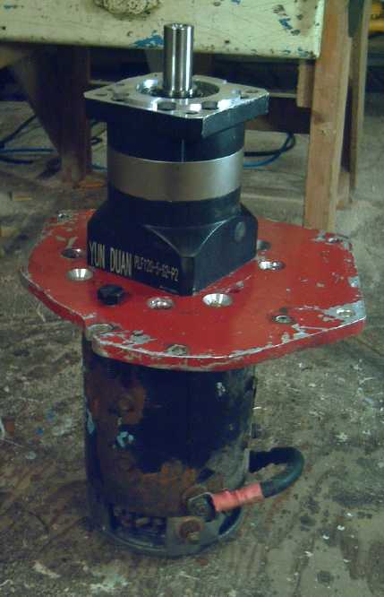
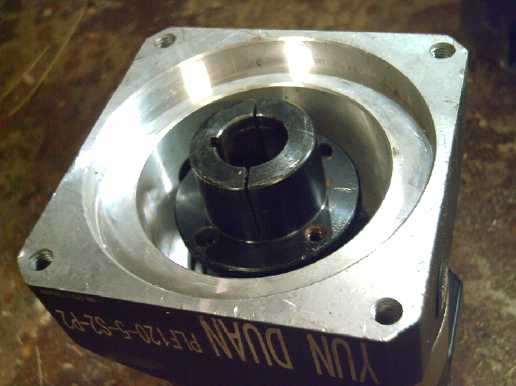
BTW the 96+% efficient Yun Duan PLF120-5-S2-P2 planetary
gearset I ordered via AliExpress.com seems great. It weighs all but 15
pounds and seems to be good quality, heavy duty. According to its
output torque specs it's only "adequate", but so far it's been be
plenty strong enough to turn
the car wheel. It won't be going half its rated RPM (which would take
the car up to about 120 KmPH) and higher speeds are at lower
torques.
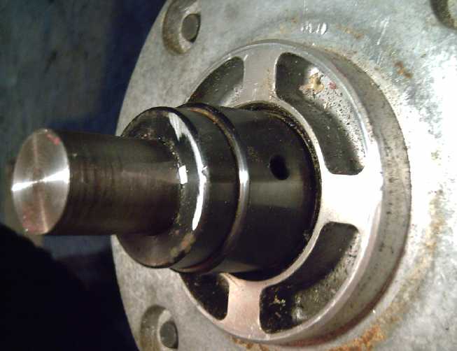
Cut CV shaft (w. paper
towel) sticking
into hood area from wheel
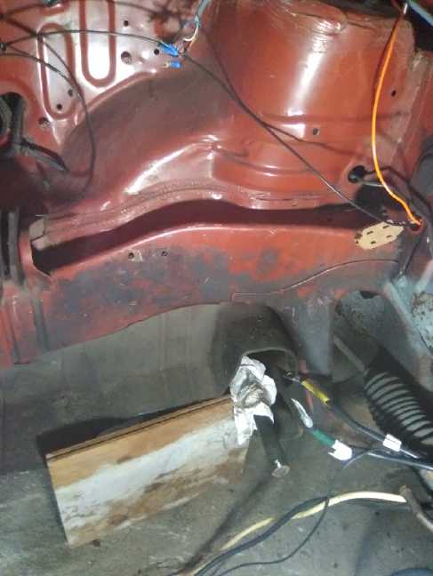 I started
sizing things up. The one obvious connection
would be a shaft coupler to make a solid connection between the gearset
output (25mm) and the CV shaft (~23mm). The gear body would essentially
become the end of the CV shaft. It would have to pivot slightly as the
wheel suspension bounced and changed.
I started
sizing things up. The one obvious connection
would be a shaft coupler to make a solid connection between the gearset
output (25mm) and the CV shaft (~23mm). The gear body would essentially
become the end of the CV shaft. It would have to pivot slightly as the
wheel suspension bounced and changed.
At first I thought I would
make a plate to hold the motor
and gearset solidly together. It seemed like the logical way. But I
wasn't quite sure how I would attach the 22mm splined motor shaft to
the 24mm socket on the gear. And that arrangement meant the motor would
also have to pivot with the suspension. I visualized the plate on a
front-rear pivot, holding the motor and gearset up and from twisting
but allowing the up-down pivot. But it seemed like it would be a lot of
inertia with the motor attached. The gear body was longer than I had
expected, and the motor was no pancake motor. (Turned out to be fine.)
Then for a while I
had decided
instead to use the Lovejoy connectors
between the motor and gear. The motor would be mounted solidly, and the
gearset would do its pivoting by slightly flexing the rubber Lovejoy
connection. That was less strong than the regular inner CV coupling,
but it also only had 1/5 as much torque being applied owing to the
reduction being after the connector. The rubber might (or might not)
wear out prematurely, but it should work well.
When I measured the length of this whole assembly, I was
surprised that it was a whole meter, 100cm. There was about 95cm
available width under the hood. It looked like I might have to cut a
few centimeters off the CV shaft. Doable.
 Thinking of attaching some shock
mounting at
front of hood (right).
Thinking of attaching some shock
mounting at
front of hood (right).
There's already one at rear (center left).
[10th] Of course mounting the motor on shock mountings would be best -
smoother and quieter. I sized the existing ones up. (Nicer if I don't
have to do any welding.) I didn't come to any firm conclusions about
what to do except that the motor placement depended on the planetary
gear placement, so that had to come first.
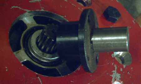
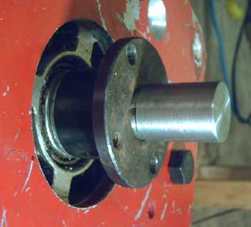
To connect the CV shaft and planetary gear output shaft, I
found "weld-on sprocket hubs" in a box, 7/8 inch and 1.0 inch. I welded
them together to make a shaft coupler for the two different shaft
sizes. (A
few of my usual crappy tack welds. I left it at that just in case I had
to take it apart again.) The gear shaft was 25mm rather than 25.4mm so
it was a bit of a loose fit, but I put the keyed coupling on anyway.
7/8 inch is 22.2mm and the CV shaft was 23mm. The hub wrecked a drill
bit and I figured it would do the same to a boring bar. The shaft
wouldn't fit on my lathe, and my neighbor with a bigger lathe didn't
seem to be around, so I ground a bit off it with the bench grinder,
being as even as I could. I left it a bit large so I had to pound it
into the hub/coupler (solid fit and not quite to the end). No shaft
key. (There was a slot in the hub/socket. It seemed like a really tight
friction fit and there were two set screws done up, but theoreticly I
should probably at least grind a slot into the shaft and put in a key.
Later.
With those fitted together, I plugged the CV shaft into
the car wheel. (Hmm, it needs some new boot clamps!)
(To retrieve the gearbox later I just loosened the set
screws and pulled it from the coupler.)
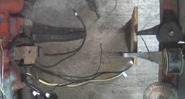
 How to mount things?
A bar from the rear/firewall shock mounting?
A bar left to right?
A way to hang a shock mounting?
Now... back to how to mount everything. I went out to the
car and pondered this long into the night. Perry had suggested welding
two supports across left to right to hold everything. But of course,
rubber shock mounts would eliminate vibration. I came up with another
way, to mount one between the right shock mounting (actually port or
driver's side, but I'm looking in from the front) and a new left
(starboard) side one. The third one on the firewall would add the
needed stability and resistance to turning torque.
Looking at it again, the shaft and all were long enough
that up-down motion of the suspension would cause only slight pivoting
at the motor end of the shaft, and I decided to couple the motor and
gearbox right together after all... if I could figure out how to
connect the shafts. The 22mm splined shaft on the motor was a tough
one. The 24mm socket on the gearbox wasn't a problem. I needed
something very short with a 22mm socket on one end and a 24mm shaft on
the other. I had just used my 7/8" (22.2mm) weld-on sprocket hub for
the other join. That left me with 7/8" taper lock shaft hubs, SD or H
type.
Assuming that would work out, the CV shaft and solid
couplings would hold the gearbox and motor straight out from the wheel.
So then the challenge would be to hold the plate between motor and
wheel in the desired position, and to not rotate with the torque from
turning the wheel. If there were two arms holding the motor, one at the
front and one at the back of the plate, forces would be up and down and
especially the front arm would be quite hard to brace against those
forces. The assembly would be prone to twisting with wheel torque. But
if there was one arm at the top and one at the bottom of the plate, the
forces would be toward and away from - horizontal instead of vertical.
I could bolt on a shock mounting and run an arm (channel or angle iron)
to under the motor from the front bar under the former radiator. There
was a support just above and behind where the motor would be, for the
top bar which could also hold up the whole 70 pound or so assembly. All
of a sudden mounting it all looked a lot simpler.
[11th] Well, I couldn't ignore everything else for long. But I figured
I could get something done on it every day. I picked "how to connect
the motor shaft to the planetary gear input socket." The motor had the
22mm splined shaft output. The gearbox had the 24mm socket. (I could
have got the one with a 22mm socket, but they weren't made to fit
together and with an interface plate between them the motor shaft
wasn't long enough anyway. or the gearbox socket was too far recessed -
take your pick.)
 I had dug out the plate from previous conversion versions. It seemed
needlessly big and ugly, but I set it on
the motor and put in the two bolts that tie them together.
I had dug out the plate from previous conversion versions. It seemed
needlessly big and ugly, but I set it on
the motor and put in the two bolts that tie them together.
After much puzzling (a couple of hours?) I took a 7/8 inch
"H" taper lock shaft hub (AKA shaft "bushing") and put it on the motor.
It stuck up about 3/8" past the end of the shaft. And it fit within the
recess in the gearbox, so the gearbox would sit flat on the plate.
 Next I cut a
short piece of shaft and turned it on the lathe. It had a short 7/8"
end that had to be pressed into the "H" hub. (I wanted to mill a keyway
into it to match that of the hub and put in a key as well for surety,
short as it was, but my fickle milling machine started fine and then
stopped running just as I was about to start milling. Click, click -
nothing happens. I would sure like to know what's intermittently wrong
with it.)
Next I cut a
short piece of shaft and turned it on the lathe. It had a short 7/8"
end that had to be pressed into the "H" hub. (I wanted to mill a keyway
into it to match that of the hub and put in a key as well for surety,
short as it was, but my fickle milling machine started fine and then
stopped running just as I was about to start milling. Click, click -
nothing happens. I would sure like to know what's intermittently wrong
with it.)
(A washer or two on the motor will set the exact spacing
with no play.)
 The "H" hub
had to go flange side up, since it's the other end that squeezes in to
lock it to the shaft, while the flange side is solid to press the
stubby shaft into.
The "H" hub
had to go flange side up, since it's the other end that squeezes in to
lock it to the shaft, while the flange side is solid to press the
stubby shaft into.
The other end of that shaft, about an inch long, was
turned to 24mm until it fit into the socket in the gearbox. When I
tighten up the bolt it will hold the piece securely and not let it
slip. (Ya, like the one in the truck? - slip, slip! Anyway being 24mm
instead of 19, it should have considerably more holding power.)
 For the motor end, I had to find something to tighten the
"H" taper lock hub around the splined shaft. For that I have a feeling
I'll have to make a very special very large washer with bolt holes
through it from 5/16" steel plate. For extra measure I might also put
in a specially shaped key that fits in the hub's keyslot and projects
into one of the spaces between the splines in the motor shaft.
For the motor end, I had to find something to tighten the
"H" taper lock hub around the splined shaft. For that I have a feeling
I'll have to make a very special very large washer with bolt holes
through it from 5/16" steel plate. For extra measure I might also put
in a specially shaped key that fits in the hub's keyslot and projects
into one of the spaces between the splines in the motor shaft.
So at the end of the day it
still needed something to tighten the "H" taper lock hub to the motor
shaft, and four new holes in the plate to attach the gearbox to it.
(All those sets of holes in the plate, and still none in the right
places!)
 After all
that, before midnight I went to my storage room
to look for something to tighten the taper lock hub, and instead I
found a stray 7/8" weld-on sprocket hub loose in a box - the part I had
wanted in the first place. It fit on the
motor almost snugly, and it had a key slot and 2 set screws to tighten
it up. It was about 1/64" too long and held the gearbox up off the
plate, but I could easily trim it down that much on the lathe. That
should solve the problem nicely! The work of the day had mostly been
making the coupling shaft, which would still be used, so little was
lost switching the part.
After all
that, before midnight I went to my storage room
to look for something to tighten the taper lock hub, and instead I
found a stray 7/8" weld-on sprocket hub loose in a box - the part I had
wanted in the first place. It fit on the
motor almost snugly, and it had a key slot and 2 set screws to tighten
it up. It was about 1/64" too long and held the gearbox up off the
plate, but I could easily trim it down that much on the lathe. That
should solve the problem nicely! The work of the day had mostly been
making the coupling shaft, which would still be used, so little was
lost switching the part.
 [12th] I got to it in the
later afternoon and made the four bolt holes
to attach and center the gearbox onto the plate. Try as I might to get
them perfect, measuring and drilling by hand 3 of the 4 holes had to be
filed out a bit so the bolts could go in the right places and the gear
be well centered (at least looking centered by eye).
[12th] I got to it in the
later afternoon and made the four bolt holes
to attach and center the gearbox onto the plate. Try as I might to get
them perfect, measuring and drilling by hand 3 of the 4 holes had to be
filed out a bit so the bolts could go in the right places and the gear
be well centered (at least looking centered by eye).
Then I started fitting the fittings. The 7/8" end of the
stub shaft proved to be a tiny bit too long, so I turned it down on the
lathe. Then the milling machine decided it was working today, so I
milled the key slot in it. I cut a 1/2" long key and after a little
filing fit it in. Then I pressed the shortened, keyed shaft back into
the weld-on hub. This time it fit great onto the motor. It also fit
great into the gearbox socket. However it seemed to hold the motor off
the plate. Later I made a couple of short steel pipe spacers to
optimally set the width of the gap.
Owing to the friction of the brush type motor being
multiplied by 5 I had to use a wrench on the planetary output to turn
everything, including the motor turning 5 times faster than the wrench.
A final point was that if the assembly was suspended by
the two bolts holding the motor, the rigid connections from motor
almost to the wheel would ensure that everything stayed in line. Still,
it would be better if the ~70 pound assembly was all balanced. [I was
unable to do as well as I wanted. It seemed fine anyway.] With the
motor and gear fitted to the plate I checked and found the balance
point (without the CV shaft) was about 2" behind the bolt holes in the
motor faceplate. Counting the CV shaft, some longer bolts and roughly
1.5 to 1.75 inch standoffs (pipes as really long washers) slid onto
them should about do it. Then the exact position and shape of the two
arms to hold everything could be determined.
[13th] The milling machine god was smiling, so I milled a tiny key slot
in
the coupler shaft stub to secure it better to the "weld-on sprocket
hub" on the motor. I made the key and it all looked good. To make sure
the motor wouldn't slip, I made a special key to fit in the hub with
the other part ground and filed to fit between two of the splines on
the motor shaft. I'm much more confident these two joins can't slip now.
I put the motor and gear assembly into the car. It looked
great except for one large annoyance: the gearbox was longer than I had
realized and the mounting plate lined up in the one place it couldn't,
right in front of the shock absorbing mount. (I should have noticed
earlier that it would be.) It seemed I could shorten the chopped CV
shaft by another 1 to 1.5 inches without causing other problems, and
that would put the plate to the side of the post. I looked for another
half hour trying to figure out some other way, but finally I just had
to take the shaft off, cut a bit off it, and do it over again.
This time I tried to mill a key slot in the CV shaft. It
seemed more like I was just dulling my titanium mill bit. (I knew those
shafts must be hard metal!) So I gave that up and tried to make it a
good "pound-on" friction fit, grinding a tiny bit of the 23mm shaft
each time and then seeing how it fit into the 22.2mm hub. (With the CV
joint flopping around on the other end, I could neither put the shaft
on the lathe nor press the coupler in with the press. But I decided
that if it slipped I could weld the coupler on.) On the last pounding
it went to about 4mm from the end and wouldn't go any further, so I did
up the set screws and barring any slips when I drive the car, it's done.
The next challenge was to get the planetary gear output
shaft into the hammered end of the coupler. Not thinking of trouble I
hadn't tried fitting them until I had put the shaft back in the car
wheel. (After all it was a 25.4mm coupler and only a 25mm shaft. Lots
of room, right?) It took a fair while leaning into the under-hood space
with files and "dremmel" type tool to get the "mushrooming" out of the
end of the socket.
Perhaps 3 hours later I had the works installed under the
hood again. This time it looked good. Well, that was more than enough
overtime for that "trivial" oversight! It was getting late and past
time for various chores, where I had hoped to be done early. Now it was
all ready except that if powered up, the unmounted motor and gearbox
would just spin until the wires broke off instead of trying to move the
car.
 [14th] With the linkages
done it was time for the actual mountings. I
anticipated quite a challenge. I started out thinking of how to connect
the firewall shock mounting to the top bolt of the motor and plate.
With the position now almost ideal, it was only gonig to need a short
piece. But the two ends were 90° different orientation... actually
more like 80° since the motor assembly was at a bit of a diagonal.
Angle iron? That would give two 90° sides. Then I thought of
twisting a plain bar of steel. I used a 1 inch by 1/8 inch bar. I
twisted it with a big vise and my favorite metal bending tool: a large
crescent wrench. Then I drilled the motor bolt hole too large (5/8"
instead of 9/16") and did it over again.
[14th] With the linkages
done it was time for the actual mountings. I
anticipated quite a challenge. I started out thinking of how to connect
the firewall shock mounting to the top bolt of the motor and plate.
With the position now almost ideal, it was only gonig to need a short
piece. But the two ends were 90° different orientation... actually
more like 80° since the motor assembly was at a bit of a diagonal.
Angle iron? That would give two 90° sides. Then I thought of
twisting a plain bar of steel. I used a 1 inch by 1/8 inch bar. I
twisted it with a big vise and my favorite metal bending tool: a large
crescent wrench. Then I drilled the motor bolt hole too large (5/8"
instead of 9/16") and did it over again.
For the other piece I had been thinking of drilling holes
in the crosspiece at the front of the car and bolting a shock mounting
there, to run a piece of angle iron to the lower motor bolt. Then I
thought a place where there had been an original shock mounting would
be close enough and would be simple to do. I bolted that mounting back
on. The rest of the same yellow painted bar was just the right length
for a strap between the plate and the mount. After drilling, bending
and twisting it a bit, it went in nicely.
I inserted the main motor bolts and pulled out the block
of wood holding up the motor. There it sat, suspended in mid air. But
for a couple of spacers and miscellaneous... It was IN! I manged to
stop myself from going any further by 4:30 PM, instead of charging
along to complete those details and getting nothing else done. (like,
making supper, having someone test play my new crossword puzzle to find
mistakes...)
 The 2018 configuration with the
"hacked"
original transmission, for visual comparison to above
The 2018 configuration with the
"hacked"
original transmission, for visual comparison to above
[15th] Having realized that if all the batteries would fit under the
hood there was no use for wiring to and in the back cargo compartment,
I pulled it all out except for a few light wires running along just
inside of the passenger doors under the carpet. It was now completely
free for cargo and a spare tire!
[16th] Well, I still had to go underneath the car and clip the cable
ties holding the power cable then pull it out. There's a few pounds of
cable removed! No more heavy transmission, this and that pulled out...
The car is getting amazingly light, but with the 75 pounds of motor,
gearbox and attachments the front suspension is no longer topped out. I
now have to lift on the bumper to hit the top end stops.
I cut two pieces of pipe (and turned them on the lathe) to
use for "just right" spacers between the motor and gearbox, and I undid
the two motor holding bolts and put them in.
Car Movement Tests
Physicly everything was ready. I got out a lithium iron
phosphate battery and jumper cables. I set the battery beside the hood
and attached the cables to the motor. With 3 volts across the motor
nothing seemed to happen. With 6 volts it crawled across the floor.
With 9 volts it crawled faster. With 12 it picked up speed and if I
hadn't disconnected it before it got there, it would have jumped over
my 2x6 "chock" and hit the garage shelves. It was all totally silent
except for the slight scrape of the brake components in the wheels that
one doesn't usually hear because other things are louder.
I went back to when I had done the car before with the
original transmission, which I had altered to give a fixed 8.9 to 1
reduction to the wheels utilizing one planetary gear and the spur gear
driving the differential. That time the car was in the same garage in
about the same place, but apparently I had connected the battery and
backed it up instead of going forward. As there was a slight and uneven
slope to the floor, going the same direction again - slightly upslope
instead of downslope - would make for a better comparison of
performance. From TE News #117:
"Using a 4-cell lithium battery and jumper cables
beside the car, it backed up a bit with 6 volts, more with 9 volts, and
up a slight incline with 12, drawing around 75 amps each time."
In reverse this time I got the following results: With 6
volts, it would back up a bit only if it was in a level spot. With 9
volts, it accelerated just a bit and slowed but made it up the same
slight incline as it did before at 12 volts. With 12 volts, it
accelerated more strongly and easily went up the rise. (I didn't check
the currents this time as they were doubtless about the same.)
While there were no precise figures for either time, these
simple voltage-performance tests seemed to show the new 5 to 1
speed
reduction to actually apply more torque to the wheel(s) than
the previous 8.9 to 1 transmission arrangement. Although 6 volts seemed
similar, in the earlier tests it sounded like the car hadn't climbed
the up-slope with 9 volts, and there was no mention of acceleration at
any voltage tested. To make sure it hadn't just got a better run at the
slope at 9 volts this time, I rolled the car to the base of it, just to
where the car stopped to rolling forward. It still went up it.
Seeming to get more torque from "n" power, instead
of
just 5/8.9=0.56 times as much, presumably indicates an increase in
efficiency of the drive train of more than 1/0.56=1.78 -- the desired
result of putting this all together and more. In fact it is a
remarkable gain. It surprised me because I thought the old transmission
was better than that. (In actual driving later it didn't seem so
amazing.)
[17th] I considered that it was
possible the battery was less
charged in 2018, but it didn't seem likely. I can't imagine having used
any battery except fully charged for tests I knew needed a lot of amps.
This time the battery hadn't been charged in months, so if anything
might have been slightly lower. But finally I got out the CD amp-clamp
meter and checked. I got around 60 amps at 6 volts, 100 at 9 and over
140 at 12. In 2018 I had been puzzled to read about 75 amps seemingly
regardless of voltage. I am still puzzled by that. Could there have
been a bad battery connection last time? Was the meter doing something
funny? Did I use the same meter? Did I in fact neglect to take a
reading at each voltage? I wish I had recorded it carefully, for each
voltage, even if they were actually similar. But let's use the figures
as given. This time it behaved more as one would expect, drawing higher
current with higher voltage. And according to theory, the torque
depends directly on the DC current.
At 6 volts it seemed to draw less current and perhaps
performed around the same, but it's hard to tell from vague
descriptions and impressions. It was very lethargic both times. So
let's forget the 6 volts.
At 9 volts it drew 100/75 amps - about 1/3 more. Instead
of rolling slowly on the level, it accelerated and went up a slight
slope. If on the 2018 tests it was actually 75 amps, then if it drew
100 amps this time it should have had 1.33 * (5/8.9) = .75, or 75% as
much torque at the wheel. Instead it performed better, climbing the
little rise that took 12 volts to climb in 2018.
At 12 volts current was (according to what I said in 2018)
almost double from 2018. By theory, torque should then have been 2 *
(5/8.9) = 1.12 times the torque. But I suspect the 2018 current at 12
volts was probably considerably higher than 75 amps and I just wasn't
paying it much attention. The motor was spinning faster so the current
drops more, but even if it wasn't near 140, perhaps it was 100? That
would make it 140/100 * 5/8.9 = 79% as much torque. Instead, rather
than either beating it by a small margin (case 75 amps) or not doing as
well (case 100A), it noticeably accelerated as it went notwithstanding
the uphill, where in 2018 it hadn't sped up - at least not enough for
me to make note of it. And
So if the new gearbox is 96% efficient and if the old one
with a higher reduction had given the same torque to the wheels, we
might guess the old transmission was around 1.4 * 5/8.9 * .96 = 76%
efficient. Since it didn't perform even that well, it was probably well
under that figure. Saying it was 70% would probably be being kind to it.
 But the 17th wasn't all about theory and performance. I
cut a piece of 3/4 inch birch plywood to be a shelf for the batteries
behind where the radiator had been, then painstakingly trimmed it to
fit everywhere including a couple of cutouts to accommodate protruding
joins in the car, drilled holes, and made a steel bracket to hold up
one corner. It was in and out many times, trim a bit and see, then
again. Then I did similar with a 1/4 inch thick piece for a front
shield so nothing flying off the road could hit the batteries. (Just in
case I actually get it onto the road!) I'll paint them later.
But the 17th wasn't all about theory and performance. I
cut a piece of 3/4 inch birch plywood to be a shelf for the batteries
behind where the radiator had been, then painstakingly trimmed it to
fit everywhere including a couple of cutouts to accommodate protruding
joins in the car, drilled holes, and made a steel bracket to hold up
one corner. It was in and out many times, trim a bit and see, then
again. Then I did similar with a 1/4 inch thick piece for a front
shield so nothing flying off the road could hit the batteries. (Just in
case I actually get it onto the road!) I'll paint them later.
Then I got out some of the still loose lithium ion
batteries and positioned them on the shelf. It should be easy to fit
two stacks, more crammed to fit three, and four would be a problem
because of the long motor strap cutting across... but doable. Two
stacks should be good enough for the 300 amps max current according to
the battery specs, but would only 8640 watt-hours. All three would be a
better 12960 WH, and a fourth stack would make it 17280 WH. With lower
energy use, that should take it as far as the Nissan Leaf's 24000 WH.
And there's room for more in the rear cargo area if I want huge range.
But to go beyond a 'proof of concept' demo, if I'm actually going to
use it on the highway with everything else the same, it'll need a
higher RPM motor.
[18th] I was otherwise occupied. I just
figured out where the battery
stacks would go, and drilled bolt holes. (battery stacks... yes, that's
why the French call them "piles" - "piles electrique"!)
[19th] I grabbed the lithium-ion battery stacks from the truck and from
the DC solar system in the garage next to the car. (I'll have to
connect up the third stack soon, but I didn't want to divert from doing
the car.) The two stacks will provide 240 amp-hours at 36 volts (8640
WH) for the 36 volt motor and 300 amp, 36 volt motor controller, and
according to the battery specs, hundreds of amps. With some
re-positioning ("moving" mounting holes a bit), I got them mounted on
the shelf under the hood. I removed the balance charger from one stack
because with the stacks connected together in parallel, two couldn't
work right. Instead I would put wires across to parallel at least every
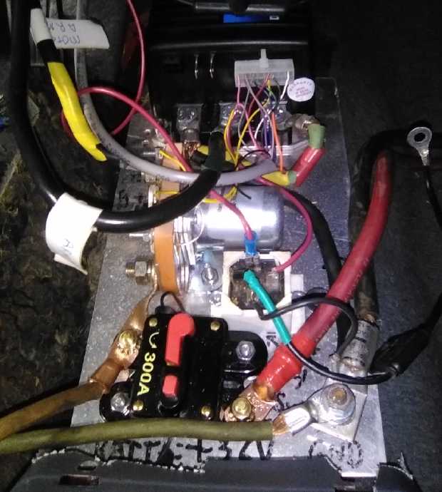
second cell so they all charge as one battery. I put in a holder for a
400 amp fuse. (And the breaker at the motor controller is 300 amps.)
I spent the rest of the time on the heavy wiring. In
connecting the minus cable to one stack, I noticed that it flopped over
onto the battery side of the fuse holder when disconnected. Fuse holder
+36V. Minus side 0V. Both straight from batteries - always live. Very
bad to touch together with heavy cable! I put in a piece of 2x6 wood as
a pedestal to hold the fuse holder way up high.
 The battery stacks bolted to the
shelf, with
cables from "B+" at the top of the stacks to the fuse holder,
The battery stacks bolted to the
shelf, with
cables from "B+" at the top of the stacks to the fuse holder,
raised to the same height with a piece of 2"x6".
I went into town to buy some lugs for #2 AWG wires with
1/2 inch holes to fit the battery main connection bolts. Then I
realized that that cable connected to the fuse, which had smaller bolts
(Duh!), so (other than having to go into town anyway) I had wasted my
time. When I had the cable ready I found it was a little too short and
had to make a longer one. At least I had enough wire and lugs.
 Then I contrived to run the heavy wires through the
firewall instead of under the floor. Yay, I can cover over that hole in
the floor between the seats, which I had used to run wires through last
time. (originally the gearshift stick hole)
Then I contrived to run the heavy wires through the
firewall instead of under the floor. Yay, I can cover over that hole in
the floor between the seats, which I had used to run wires through last
time. (originally the gearshift stick hole)
I replaced the under-rated 135 amp circuit breaker
(biggest one I could get in Victoria when I was living there with a new
300 amp breaker of the same physical size.
Finally I was left with one control wire that I wasn't
sure where it went. Only then did I notice that the wiring diagram had
vanished somewhere. I decided I should leave it all until morning and
go over everything before I powered it up and tried to run the car.
Before bed I downloaded the manual for the 1243 type motor
controller again from Curtis and found where it went. I printed out the
control plug pinout and the wiring diagram.
First Test
[20th] I wired in a ground from the battery minus to the car body - not
something to omit! In a higher voltage system one would keep the drive
power system separate and make it floating ground so as not to
electrocute anyone. With 36 volts that's not necessary. But
I didn't want to hook just some of the cells up as the 12 volt supply.
So I put in a 12 volt battery - one made of four of the 40AH LiPo cells
that have been kicking around for some years now. (That will need some
charger too.) Everything seemed to work except the headlights. (Not
those cursed headlights again! Days later I discovered, or
rediscovered, that there was nothing wrong: the headlights only come on
if the parking brake is off.) When everything seemed ready I put a
500 amp fuse in the holder on the 36 volt line and closed the circuit
breaker.
When I turned the key (drum roll... suspense...) nothing
blew up. The contactor clicked. I pressed on the gas and the car moved
forward. So I opened the garage door, moved the other cars out of the
way and pushed the Sprint out of the garage. (I still haven't done
anything about getting it to run in reverse.) The driveway being
cluttered I drove it across to the far side of the acreage. It seemed
to move well enough and climb little humps that the badly geared Miles
Truck had sometimes had trouble with. Driving so far from the garage
was a
mistake. Perry came along. We got it turned around, and he sat in the
passenger seat. But one wheel was in a hole. It took extra force to try
and move the car. And it didn't.
Something squealed and the car didn't move. We looked and
found the long yellow bar had bent. (Driving forward pushes on that
support instead of pulling on it.) Walking back and forth across the
acreage I eventually shaped a 1" x 2" steel tube into a new, stronger
motor support.
But that wasn't the end of it. Perry's eyes were valuable
to seeing the problem. The CV shaft had started
slipping in the shaft coupler. Suddenly (and belatedly) it occurred to
me that I even if the shaft was too hard to mill a keyslot into, I
could have ground one in with the angle grinder. And I should have made
a couple of flat spots for the set screws. Now, unless I was going to
tow it back, it all had to come apart again, out in the weather, at the
far end of the property.
Luckily both this afternoon and the next day the sun came
out and it was, for a change, nice weather.
[21st] Between the truck and this, I was tired of slipping shafts. I
took the mechanical parts apart. I started gouging a key slot in the CV
shaft. The hub had only a 5/32 inch keyslot. Why so small? After a
while I thought, why do it this way?
If the keyslots were inappropriate, what else was there?
For DIY mechanics, making splined shafts seemed like a more than
daunting task. But one could easily make a shaft square with a grinder.
Making a square socket was another prospect. Too bad no one seems to
sell them. But did one need to do that?
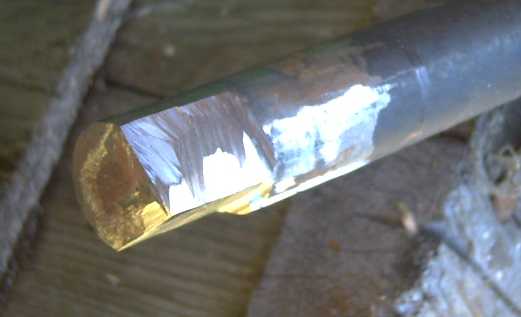 The coupler
socket had two set screws at right angles. If
they hit in an indented area instead of on the very outside of the
shaft, the shaft couldn't slip. And why settle for a small indent? I
took the angle grinder and ground the shaft to square on two faces at
right angles, matching the set screws.
The coupler
socket had two set screws at right angles. If
they hit in an indented area instead of on the very outside of the
shaft, the shaft couldn't slip. And why settle for a small indent? I
took the angle grinder and ground the shaft to square on two faces at
right angles, matching the set screws.
 Then, the setscrews were 1/4 inch (1/4"). Why had
they
used such tiny ones? They might just bend, or the metal around them
bend and let them rip out. I drilled out the two holes larger and
threaded them for 5/16". Then before I did anything else I changed my
mind and drilled them out and rethreaded to take 3/8" set screws.
Then, the setscrews were 1/4 inch (1/4"). Why had
they
used such tiny ones? They might just bend, or the metal around them
bend and let them rip out. I drilled out the two holes larger and
threaded them for 5/16". Then before I did anything else I changed my
mind and drilled them out and rethreaded to take 3/8" set screws.
 Squared shaft, beefy 3/8" set screws... let's have a setup commensurate
to the job! 200 or more foot-pounds on an axle is a lot of torque.
Squared shaft, beefy 3/8" set screws... let's have a setup commensurate
to the job! 200 or more foot-pounds on an axle is a lot of torque.
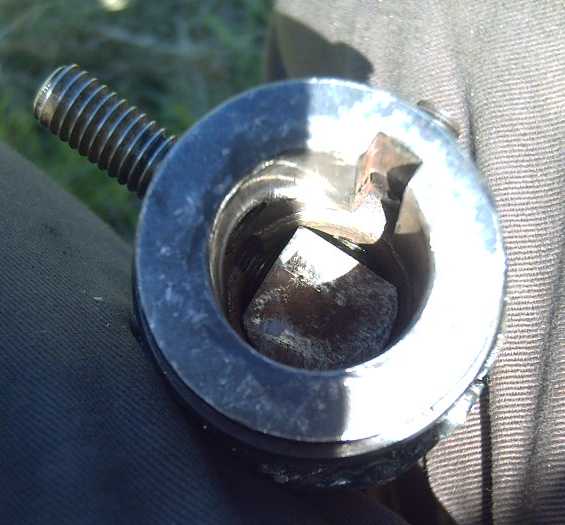
 The gearbox end's socket was similar except 5/16" set
screws. Same hub except different shaft size - why the difference in
screws? And why did one have a 5/32" key slot and the other 1/4"? The
gearbox shaft's key slot was about 5/16ths" (8mm?) so it didn't match
the 1/4". I ground another square face into the gearbox shaft at
90° to the keyslot. I got fancier and made it so the setscrew
couldn't slide off the shaft - not that it could anyway in this setup.
I threaded that setscrew to 3/8" but left the other. The other wound
nicely into the key slot with no key in it. I figured that one wasn't
going to slip either.
The gearbox end's socket was similar except 5/16" set
screws. Same hub except different shaft size - why the difference in
screws? And why did one have a 5/32" key slot and the other 1/4"? The
gearbox shaft's key slot was about 5/16ths" (8mm?) so it didn't match
the 1/4". I ground another square face into the gearbox shaft at
90° to the keyslot. I got fancier and made it so the setscrew
couldn't slide off the shaft - not that it could anyway in this setup.
I threaded that setscrew to 3/8" but left the other. The other wound
nicely into the key slot with no key in it. I figured that one wasn't
going to slip either.
 Before I put
it all back together, I beefed up my tack welds on the coupler. No
point having everything else toughened up and have the welds snap when
I drove!
Before I put
it all back together, I beefed up my tack welds on the coupler. No
point having everything else toughened up and have the welds snap when
I drove!
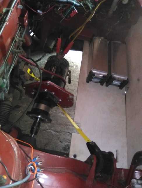
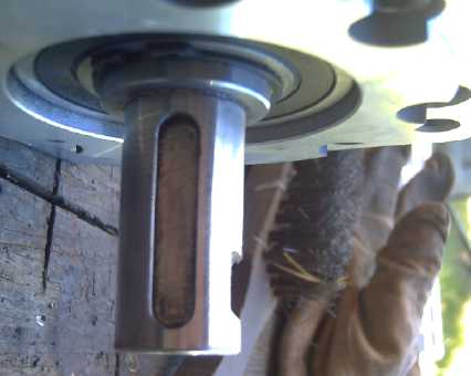
With replacement rectangular bar
(left:
diagonal, red) to take the torque,
beefed up linkages to CV shaft,
and charging from solar DC supply in garage with monitors.
When I had everything back
together I got in and drove the
car back toward the garage. It seemed to have sufficient
pickup. It
rose out of the dip I couldn't push it out of by hand. There was a bit
of
vibration when I got up a little speed, but not bad. (The lawn trail is
too bumpy
to get going very fast.) I stopped at the corner at the base of a hill
just before reaching the "usual" part of the driveway. I thought I'd
see how it did up a hill from a stop. In the winter the Echo and the
Leaf had slipped on the wet grass and in the mud (and barely made it
up). Now the mud was hard ground.
It was more challenge than I had expected. I had to press
the pedal pretty hard starting up the hill, and the one-wheel drive
slipped in the wet grass. Eventually I got it worked around so the tire
hit the narrow pea-gravel trail I had made up the hill. Now I had to
push the pedal a long way down to go anywhere, but it started climbing
the hill without slipping, and speeding up just a bit. 3/4 of the way
up, the 300 amp circuit breaker popped. (The motor was still cold. I
didn't feel the controller.)
Then I looked around for the Curtis motor controller
handheld programmer, which I hadn't bothered with to that point, to
look at currents and other readings. I didn't find it. (Where did I put
it after I was trying to get it to work in the truck, many months ago?)
I got some more pea gravel and put some under the tire. I still
couldn't get the car moving up. It either wouldn't budge or would skid.
The driving (right) wheel was up and the car leaning to the left, so it
had less traction than if it had been level. The drawback of single
wheel drive was made obvious. I was also starting to wonder if the 5 to
1 gear ratio was enough, given the "full throttle" high current to
climb a hill at very low speed. The tiny biting midges ("no-see-ums")
were coming out in force (as they had every evening for a month), so I
closed up the car and left it on the hill.
The torque seemed fine for level pavement, but once I was
trying it out on a hilly lawn, it didn't seem to be
going as smoothly as hoped!
[22nd] I
jacked up one rear wheel and slid a board under it. Then I put
wedges under the board to make it a ramp, so that one wheel was going
downhill instead of uphill. I put some more gravel under the drive
wheel. It went forward until the rear wheel was off the ramp and the
front was off the gravel, then it just slipped again. After 3 sessions
of this, the front wheel was facing steeply uphill in a little hole,
and after gravelling it it would neither spin nor move. A ramp on both
back wheels finally budged it. It may (or may not) have made it up the
hill if the breaker hadn't blown.
Later I drove the car in a loop around the 'main'
driveway, before I lost my nerve for driving it anywhere. That area is
more level but still has hills and bumps. It seemed to have enough
pickup there except for still easily skidding on the grass. Well, I
never expected it to be an "off road" vehicle, and they're certainly
not "off road" tires, either.
[23rd] I drove around the driveway again
3 times to verify my
perceptions. At least nothing was slipping or seemed to be bending or
coming loose. I made up a socket connected to the balance charger, and
a cable from an old extension cord with another socket. The other
end of that went to the DC charging system, and I soldered up a little
male-male plug to connect the two sockets together. Now I could charge
the betteries in the car from the DC solar power system, and I
proceeded to do so. Between them I plugged in one of the little power
meters. It was cloudy and only 300 watt-hours went into the car before
dark, raising the voltage from 38.9 volts to 39.1. I plugged the car
batteries into the house DC power system. So the car was now charging
from solar panels on the house and powering the house DC system.
And I found the Curtis handheld motor controller
programmer. (Ya, right on a back corner of my cluttered desk where I
had already looked a couple of times!)
[24th] I decided to be brave and try crossing the acreage again. This
time I had the programmer hooked up. It was routinely showing currents
of 150 to over 200 amps on the rough lawn as I drove, less on down
slopes or if I eased off the pedal. On the return I took a good run at
the hill as I rounded the corner. Although gradually slowing as it
climbed, it looked like it would make it up handily when the so-called
"300 Amp" breaker blew again, just 3-1/2 feet past where it had done
last time, and it came to a quick stop. Humpf! Where the original 135
amp breaker (that didn't blow even at the highest currents) was a
"thermal breaker", this one, which said nothing on it, must have been
some "fast blow" type. (In fact, there was no way it was "300 amps".
More like 100.) Also, the handheld programmer, on which the
readings did jump up and down each second, never showed more than 270
amps. Why would it be acceptable for a breaker to blow anywhere below
its rated current even for an extended period? I think I'd better find
a different brand of breaker.
It took 3 back wheel rampings to get up to where the car
would go on its own.
 [25th] I wired a T36 socket
to connect a DC to DC converter to so it would
charge the 12V battery but only when the car was running. (The
headlights were running it down.) And I 3D
printed some hole glands for the holes where the wires went through the
firewall to the motor controller. The sides of the holes seemed smooth
enough, but it would be bad news to have the insulation rub off a wire
and connect it to the car body.
[25th] I wired a T36 socket
to connect a DC to DC converter to so it would
charge the 12V battery but only when the car was running. (The
headlights were running it down.) And I 3D
printed some hole glands for the holes where the wires went through the
firewall to the motor controller. The sides of the holes seemed smooth
enough, but it would be bad news to have the insulation rub off a wire
and connect it to the car body.
[26th] I replaced the "300 amp" breaker
with the old 135 amp breaker
and wired in the 12V battery charging socket. Then I took the car for
another spin across the acreage. This breaker didn't blow and with a
fair run at it, it made it up the hill. Not, it must be said, with much
to spare. If the hill had been a little longer or a little
steeper, it probably would have stalled. So I did it once more, and
this time it
still had a bit of speed at the top of the hill. I must have got a
better run at it or something - not that one should count on that in
evaluating a drive mechanism!
On the "level" parts of the bumpy lawn at an somewhat even
speed the programmer read currents of about 100 to 170 amps. It
probably would have been less on pavement, even going substantially
faster, but it seemed like a lot of power. I looked back at my 2018
notes (TE News #119) to see what the currents were then, and discovered
that I had had quite different readings from the Curtis programmer than
from the DC clamp-on ampmeter. Of course! The armature currents aren't
the same as the DC current from the battery. The currents in the
armature go in and come back out again, often not in phase with the
voltage, so they were for the purposes of power measurement somewhat
meaningless.
So I got out the clamp-on and hooked it to the battery
wire where I could see it while I drove, and did a third turn. It was
showing currents like 30-40 amps as I started moving and mostly around
30-70 amps driving along the bumpy lane. If I hit the electron pedal it
went up to 90 or 115 or whatever. Climbing the hill on the way back at
one or two points it broke 200 amps, but mostly (from my few glimpses)
was still under that (eg 170A). So! It wasn't using oodles of power
after all. It was probably using about the same amount for driving the
same speed on the same ground as in 2018. And hopefully a bit less with
the "ultra efficient" drive train. 50A*36V=1800W or 2.4HP. 200A*36v on
the hill is 7200W or around 9HP. With the "too-low" drive ratio,
probably some of the energy was used generating heat rather than
thrust. BTW it made it up the hill easily. A good, thrilling run into
that corner is the key, and I seem to have acquired the knack for it!
(The much longer driveway is still a more than dubious prospect.)
[28th] I hooked up a DC to DC converter to charge the 12V battery to
13.5V, and it took some charge. But the converter was a bare circuit
board with no case. I was afraid of a short circuit to the car body and
I removed it. I'll have to mount it properly.
I started using the car for hauling lumber from my stacks to the
shop and the building site for the firewood shed, and then for bringing
tools a supplies to the garden instead of walking back and forth
multiple times. On one occasion I stopped at the new shed near the base
of the hill. The wheel slipped a couple of times as I tried to
accelerate and I got the car stuck on the hill again - virtually at the
top of the steep part, but with the wheel slipping on the grass. I got
out and looked and saw it was slightly flatter to the left. I turned
the wheels to the left and the car crept ahead and made it up. This
time I had the DC clamp-on ampmeter connected and was looking at the
battery currents. They seemed to be below ~120 amps with the motor
stalled or nearly so, but rose some when it picked up some speed, still
"floored". I saw some 180 amps and even over 200 a couple of times.
(and a "300 amp" breaker had been blowing?!?) Current dropped as the
car picked up even a little speed (there was no room to go "fast") and
I let off the pedal, and usually was soon down to 30-50 amps. But if
"booted" while moving it could momentarily go perhaps to 200 amps
picking up speed. (200A * 36V = 7200W = 9.64HP)
On one trip on the 29th something smelled to me like
burning semiconductor when I got in the car and started moving - uhoh!
I turned it off and opened the hood, but there was no smell except in
the cab, and that had dissipated too. Everything still worked okay
including the stereo. (Motor controller, stereo... what other
electronics was there? The jumble of wires that used to go to the
engine and transmission, that I've never quite had the nerve to start
chopping? A puzzle.) When I was done I unplugged the 12V battery and
turned off the 36V breaker to the motor controller. No power to
anything. If something is going to go, at least it should happen while
I'm there to see it - I'm not fond of vehicle fires starting while no
one is there! (July 1st: mystery solved...? I rinsed off the car and
then turned the windshield wipers on. After a few wipes, which seemed
slow and labored, smoke and that smell were coming out from behind the
wiper control buttons on the dash. I don't remember using the wipers
before, but that was the smell, and I do remember hitting lights and
wiper "off" buttons just in case. Probably the wiper motor needs oil or
something, having not been used for so long, and is drawing too much
current for the speed regulator.)
I didn't see much (any) movement of the trip meter over
several days of short travels. When I finally thought about that, of
course!: the speedometer and hence also the odometer had no connection.
The gear to run them had been inside the original transmission. I got
on line and after some searching found that bicycle speedometers come
with all required parts and had a software adjustment for any
(reasonable) wheel diameter. They count revs magneticly and translate
them into speed and distance units. I ordered one. (Oddly the display
only goes to 99.9 KmPH.)
[Later] I found there was a problem with the DC to DC converter to
charge the 12 volt battery. When the 36 volts was off, it burned out.
(I had felt a little transistor on these getting really hot a couple of
times before, but I hadn't understood why.) Apparently it didn't like
having power on the output side when the input side had none. I put in
a schottky power diode with a heatsink to isolate it, but it isn't
mounted properly. (Hmm, I should attach it to the battery post instead
of having it at the converter end of the wire.)
 Mind the seat covers, eh!
Carrying lumber across the yard
for the
firewood shed
Mind the seat covers, eh!
Carrying lumber across the yard
for the
firewood shed
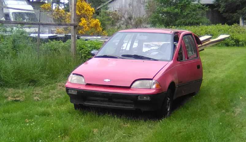 Okay, I could have closed the
hood both
notches, and the door, for the photo!
Okay, I could have closed the
hood both
notches, and the door, for the photo!
Conclusions
Other than the wipers and the odometer, I didn't note any
mechanical or electrical problems after the first fixes, in 15-20(?)
bumpy drives across the acreage and back including hauling lumber. It
all seemed to run quite smoothly - just a bit of gear sound under load
from the planetary gearbox, doubtless to be expected. No notable
vibration. The motor suspension system gets a good workout, and it
seems to work fine (AFAICT from inside the car, and from "jumping" the
front end up and down with my weight on the bumper). The two-point
mount allowing the drive assembly to pivot up and down with wheel
bouncings is simple in theory and seems to work great.
There's quite a lot of motor/wheel torque force and stress
on the motor shock mountings, which may or may not cause trouble some
time. (But they are two of the four that held the original motor and
transmission.) I just used the car's existing shock mountings, one of
which especially is not ideally located for this. If it becomes
necessary, I'll change the arrangement, but it's been fine so far.
In a hard stop with brakes pulling more on one side than
the other, a sideways pull on a vehicle is very noticeable and must
be corrected for by steering. (The Mazda RX7 EV had one rear brake
stuck off for a time, and I certainly noticed it.) It is in law that
vehicle brakes must not appreciably pull to one side. However, some
earlier
front wheel drive cars (1975 VW Rabbit comes to mind) pulled notably to
one side when you stepped on the gas. With this single wheel drive I
never noticed any pull to one side at any time. But then, I couldn't
get it going very fast in my lawn-trail tests.
It occurred to me that part of the drive wheel skidding
problem was that the car was so light, the drive wheel was on the
right, and most of the added weight was on the left: the driver, the
motor and the batteries. Just the 15 pound planetary was a bit right of
center. Plus, while the tire had good tread, it was for pavement,
certainly not an "off-road" tread. (The lawn tractor with somewhat
similar
"turf saver" tires also does a lot of slipping going uphill.) Plus the
very lightweight car was leaning considerably to the left on
the hill. So withal, the wheel had the least possible weight pushing it
down, giving it extra proclivity to spin in the slippery
grass going uphill. I suspect driving a rear wheel would work somewhat
better,
that it could push harder without slipping because the weight shifts
somewhat to
the back going uphill. Still it seemed to prove single wheel is
really a drive for pavement.
Slipping aside, it would seem I went too far trying to do
just a 5 to 1 reduction - with this motor. I did know from the start
that
even with a 96% efficient drivetrain that was pushing its boundaries.
Obviously when push came to shove there was substantially less torque
to the wheel than with the previous 8.9 to 1 with the "hacked" original
transmission. With that it had made it up that hill without me making a
note of it, and it made it up the driveway okay. (OTOH in 2018 no doubt
I 'booted'
it in the turn heading into the slippery hill as I did especially each
time entering the driveway,
rather than daring it to do its worst by stopping at the bottom.)
With a protractor I estimated the angle of the wheels to
climb in the several steepest spots as being around 15°. There are
similar angles in my driveway and it's longer, so I'm pretty sure if I
drove down to
the highway it wouldn't get up into the yard again. (I guess the little
hill at the back is steeper in places than I had realized. No wonder
I'm always
surprised when vehicles are struggling on it, especially when it's wet!)
 Hmm, the driveway in is shorter
and steeper
than the picture makes it look (wide angle camera)
Hmm, the driveway in is shorter
and steeper
than the picture makes it look (wide angle camera)
6 to 1 might not (or might) have been just sufficiently
better to make the
difference for the driveway. I would probably have got away fine with 7
to 1 - 40% more torque. Even with a 96% efficient planetary gear, 5 was
making it just a little too hard to drive the wheel on a steep slope or
in a "pothole" type situation. At the other end of considerations, at
8.9 to 1 it would only do 25 KmPH. At 5 to 1 it should then do 45 - at
least a
potentially semi-useful speed.
Of course, all this is with this particular rather small
36V forklift
motor driving everything (and this particular 300A motor controller).
Other than being series wound,
36 volts and 51 pounds, the specs for this old motor are unknown to me.
(Most of the label is illegible. I did
search the web, but didn't find anything. Knowing the "locked rotor"
torque at say 150 amps from the battery would be valuable. Hmm...
Looking back at TE News #119, Sheldon said it was 3.5KW. I had
forgotten that. That's 4.67HP, and about 100 amps from the battery -
doubtless the continuous rating, not absolute max. I did push it well
beyond that for brief periods.) It seems to go up to around
2000-2200 RPM with no inclination to want to go higher. (I suppose I
could have got a 48 volt motor controller (400 amps?) and 48 volt
batteries and it would go 48/36 times faster. And have more torque.
That would be pushing a 36V motor beyond its ratings. I would hate for
it to burn up.)
It comes back to the same old dilemma: To use a smaller
motor to drive a car, one needs an efficient transmission with
different gear ratios - preferably the 100% efficient variable torque
converter, preferably followed by a 2 or 3 to 1 fixed reduction to have
the motor at favorable RPMs when the variable part has dropped to 1 to
1/no slip. (A second reason I picked a 5 to 1 planetary gear was that
it seemed like a good ratio to use to make such a torque converter if I
decided to try using it for that.)
A 96% efficient drivetrain would be fabulous for any
vehicle. Less power and torque required mean a smaller motor or engine
and less
energy consumption for the same performance. This layout with no spur
gears anywhere is about the most efficient possible design - hard to
beat 96%! Two motors and planetary gears
driving the wheels on both sides would of course have more grip on the
road. To fit two motors into most smaller (narrower) cars, that would
require
planetary gears that are short in length (should be simple to produce),
and pancake type short motors... like the motors I've made and want to
do a new, improved model of... someday when I have time!
The single motor would need
somewhat more torque than the present one for a good 5 to 1. Another
25-40% perhaps? And if it's to be a fixed reduction ratio, any motor
will need to be substantially higher maximum RPM (than ~2200): 3000 for
60 KmPH
for around town and 4500 RPM for 90 KmPH for any sort of highway
driving. To achieve both more torque and higher RPM probably means
using a bigger motor... or perhaps the new plan of the Electric Hubcap
"outrunner" type [next article below].
New
"Electric
Hubcap"
"Outrunner"
Motor
Thoughts
[24th] Having decided the Sprint drive was very good except that the
motor had a bit too little torque and too low a maximum RPM - and was
surely not all that efficient - I started thinking about motor design
again. Permanent magnets attached to the inside face of a spinning rim
should be safer at a considerably higher RPM than magnets simply
glued to one side of a flat spinning disk. Was there any reason the
axial flux couldn't be made radial, but with the same large flux gap
axial uses instead of the miniscule gap radial flux typicly has? I
couldn't think of any reason. My existing internal unit motor
components are all "flat" for axial
flux. The larger the motor diameter, the closer to "flat" they would
ideally be for radial flux (instead of each piece being an arc to fit a
particular diameter). If I can get away with using my flat pieces, an
"outrunner" configuration with the magnet rotor outside of the stator,
magnets facing in, seems like a great choice. And surely the large flux
gap would make that feasible.
I
got out some spare coils and cores and set them around a
blank 300mm diameter "Improved Piggott Alternator" rotor disk. With 12
coils spaced equally facing outward, the spacing seemed just about
right. Assuming the same wound diameter would apply whatever the
optimum number of winds and gauge of wire, there was just a little free
space between coils. I assumed they could be fitted in so 300mm would
be the
outermost diameter of the stator.
Then if the magnets were 1/2 inch thick and flat rather
than curved, but facing sideways, they might occupy 14mm instead of
12.7.
So add 2*9mm for the flux gap and 2*14mm for the magnets, and 2* 6.4mm
for the 1/4" outer rim thickness, and the rotor outer diameter would be
359.1mm or 14.14". That's an appealing diameter - slightly smaller than
axial flux works out to with the same components, yet it should provide
quite a lot of torque. Would it be 30-40% more than the forklift motor
with similar currents? No guarantee, but I
would expect so.
One face of the outrunner motor can be either motionless
stator section or one side of the rotor. The other face and the outside
rim have to
be the spinning rotor. It's better to have a non-spinning side to
mount. Then the side of the drum and the center axle have to be quite
rigid and strong. But if the side were, say, an inch thick, and made of
tough polypropylene-epoxy, it could be strong and wouldn't weigh much.
Only the outer rim need be heavy steel, to carry the magnetic flux
between magnets. It could be for example a rolled up piece of 1/4" x
2.5" or 3" steel bar or plate: 2" wide for the magnets plus .5" or 1"
to
attach to the PP-epoxy side disk.
[ Hmm... "Safe at higher RPMs" assumes it's well balanced, and that the
drum rim is safe from ripping apart. If it is a rolled up mild steel
bar, it should be very strong except perhaps for the joint. Welding on
an extra layer of steel there would be reassuring... except for making
it badly unbalanced. What is strongest... or are any of these good
enough for say 5000 RPM? (4000? 3000?):
a) a welded joint?
b) a beveled joint (hence with a large surface area) silver soldered?
c) a beveled joint brazed? ]
____ ____
( ___/ /_____ ...beveled through the thickness,
with more horizontally sloped "/"es )
One could of course put a PP-epoxy case around the whole
motor so on the outside, only the shaft would turn. Is that valuable,
or
just extra weight and size?
The coils could mount on the outer face of an inner rim.
In fact, the stator could be mostly molded PP-epoxy too. Here once
again we would have the essential lightweight, ultra-efficient
'Electric Hubcap' motor design. It might be under 50 pounds and have
substantial torque and higher safe RPM than the axial flux models.
I
visualize inner steel components: shaft with the inner
portion of the rotor side wall welded to it at right angles, and the
inner part of the stator side wall with a "pipe" to hold the bearings
and the shaft within. Thus, two steel side wall center portions, one
spinning and the other stationary, to bolt the plastic pieces holding
the rest onto. Hmm... might they even be a trailer hub and stub axle,
available in stores? Well, almost. Maybe with the hub turned shorter as
in some of my earlier experiments, so the axle sticks out?
Checking in the shop (why am I going out to the shop in
the dead of night?): sure enough, those look just right - the very
parts needed, robust and strong -
virtually made to order!
Other "Green" & Electric Equipment Projects
Off-Grid
infrastructure Components
Having created these
components for off-grid energy, I decided to put them to use. In the
first days of the month I got out a spare 305W solar panel, and the
setup, and took them outside to where six golf cart batteries sat,
that, although having had a sodium sulfate battery renewal treatment,
had been discharged to zero - again - by the Miles truck and removed. I
wanted to try connecting a 12V lead-acid battery to a 30+ volt solar
panel, for which equipment has always seemed elusive. The only way to
do it is to connect an MPPT charge controller, but those are more
expensive and PWM - pulse charging - is the better way to charge
lead-acids: they last longer and renew better if discharged.
So for charging I used a DC to DC converter set to about
15 volts output and connected that to a typical cheap PWM charge
controller, going to two of the 6 volt golf cart batteries (the ones
savagely discharged by the truck to zero or less) in series
for 12 volts. I also plugged the two monitors in, one between the solar
panel and the DC to DC, and one between the PWM controller and the
batteries. Those gave me a good view of what was going on. Finally I
plugged in a 5W DC light bulb in a socket straight to the battery and
left it on. Thus the system would charge during the day and discharge
some at night.
The charging didn't work right. I had expected the charge
controller to find the maximum power point from the DC to DC converter,
but instead, if there wasn't enough available from the solar panel to
match the maximum current setting on the converter, it just dragged the
solar panel voltage down to its own output voltage - not much higher
than the battery voltage. If the DC to DC is working, the current to
the 12V charge controller is almost three times higher than that from
the 36V panel. If it drags the panel voltage down to the battery
voltage, it gets no more current than the panel's "semi-shorted" output
current. You would think the charge controller would notice that the
maximum power point goes way up if it backs off its demands a bit, but
it doesn't. So the DC to DC converter maximum current has to be set
lower than the available solar panel power, which of course varies
continually.
Other than that, there was
plenty of power regardless of
using the panel badly, and the setup worked nicely. The batteries
started out a 8 volts, but were up to 11.something after a while, and
the two batteries were pretty balanced. It surprised me that there were
no shorted cells. Each day the battery voltage got a little higher at
and after dark running the light: 11.?, 12.0, 12.15, 12.3, 12.45, 12.6
and by the 11th it was holding over 13 volts (at least for a bit after
the panel was disconnected) during the day. Gosh, if their capacity was
really being restored to the full 180 amp-hours, maybe I could use one
pair in the Miles truck again plus the 5 sets of 100AH, 12V
lithium-iron-phosphates, and have the 3 stacks of 120AH, 36V
lithium-ions for the Sprint.
I moved on to the second set of batteries to see how they
would fare on the 13th, and whether the first pair would hold their
charge well. One of the second set was stronger than the other. It held
6.3 volts. The other decayed over some days to 5.5. Of the third set,
each battery had one shorted cell and they didn't "unshort", so they
gave only 8 volts instead of 12. (I thought they were over 10 volts
once, but later they were at 8 again.)
By the end I seemed to have three good ones and three with
shorted cells.
With getting the Sprint running and solar charging set up,
I fully employed the previously made power meters and made up several
more plugs, sockets and cords to connect things together, that
previously would have been hard-wired: a cable to charge the main
batteries from the DC solar panel system on the house roof through the
10S li-ion balance charger, a 36V socket on the batteries for a
voltmeter, another going through the ignition to run a DC to DC
converter to charge the 12V battery while the car was running, another
plug and socket to connect that battery to the car's 12V system itself.
All these seemed to show the utility and the need for such
plugs and sockets. I was rapidly depleting the inventory of 3D printed
plug and socket shells I had made. There should also be click-lock
types: this is a car and it certainly wouldn't do to have something
come unplugged, especially while driving. (It was bad enough having the
so-called
"300 Amp" circuit breaker trip and the car lose power while going up a
hill on the acreage!)
Innovative
Beekeeping:
The
Bee
Barn
I finished the "Bee Barn" on the 8th. First I made "Nuc
Holders" to extend the frame that come in a "nuc" (nucleus beehive) to
the extra deep "Bee Barn" height. The extension is a chopped piece of
"standard" frame, attached underneath where the nuc frame will slide
down to. I made one - one pair of edge holders - of metal, but it
seemed like a tedious process.
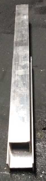 So the
remaining four (five frames in a nuc) were thin ABS, formed in the oven
into "U" shapes for the frames to slide into. I found a couple of
pieces of aluminum to conveniently form the bends by pressing them
together with the plastic between. (You have about 10 seconds after you
take the hot, floppy plastic out of the oven before it has cooled too
much and stiffened.) The gaps were a bit small and after the first one
I was sometimes unsuccessful at getting a satisfactory shape. After the
third one (and about the 6th try) I thought to bend the outside piece
just a little in a vise to expand the gap on one side. The last one was
easy and perfect! (If I ever have to do more, I'm all set!)
So the
remaining four (five frames in a nuc) were thin ABS, formed in the oven
into "U" shapes for the frames to slide into. I found a couple of
pieces of aluminum to conveniently form the bends by pressing them
together with the plastic between. (You have about 10 seconds after you
take the hot, floppy plastic out of the oven before it has cooled too
much and stiffened.) The gaps were a bit small and after the first one
I was sometimes unsuccessful at getting a satisfactory shape. After the
third one (and about the 6th try) I thought to bend the outside piece
just a little in a vise to expand the gap on one side. The last one was
easy and perfect! (If I ever have to do more, I'm all set!)
 The aluminum-edged extender frame
and
The aluminum-edged extender frame
and
a plastic one with a "regular" frame slid into it.
The "barn" with some edge insulation and plywood spacers to "shrink" it
down for fewer bees,
a couple of extended frames, and the "nuc extender" frames, one with a
"nuc size" regular frame slid into it.
The last step was the little roof over the entrance area.
This should allow the bees to stop getting wet even before they land,
instead of not until after they enter the hive. In a damp area this
whould make a notable difference.
I put it up on a previously made stand and set it out on
the lawn. But no bees have been forthcoming from HiveWorld, who haven't
returned my phone calls or e-mails. With July here I think I'll just
let it pass and absolutely insist on a delivery of the Carniolans next
spring. Too bad - some great bee honey production weather has just come
and gone in the last week of June and the first one of July.
Electricity
Generation
My Solar Power System
Daily/Monthly/Yearly Log of Solar
Power Generated [and grid power consumed]
(All times are in PST: clock 48 minutes ahead of sun, not PDT which
is an hour and 48 minutes ahead. DC power output readings - mostly
the kitchen hot
water heater for some months, since its removal mostly just lights -
are reset to zero
daily (mostly for just lights, occasionally), while the others are
cumulative.) Note that the DC is actually power used since there's
nothing totaling up the amount incoming to the batteries, which is
(unless it's a lot and there's little sun) replaced the following day.
Solar: House, Trailer, (DC@house) => total KWH [grid power
meter
reading(s)@time] Sky conditions
Km = electric car drove distance, then car was charged.
May
31st 1634.46,644.31,(.12)=> 5.89 [85127@2100] Is summer coming? Is
summer coming?
June
01st 1636.71, 646.10 => 4.04 [40Km; 85140@21:00]
02d 1642.57, 648.89 => 8.65 [85156@26:00(2AM)]
03rd 1645.11, 650.20 => 3.85 [85166@21:30] MORE cold,
cloudy days? Worse than May? Which was worse than April? Seriously?
04th 1648.93,652.35,(.16)=> 6.13 [60Km; 85186@20:30]
05th 1654.23, 655.25 => 8.20 [55Km; 85210] Just a wee
bit
of sun!
06th 1661.45, 659.19 => 11.16 [90Km; 85232@19:30] and a little more
sun. Then more rain.
07th 1666.96, 662.25 => 8.57 [45Km; 85252@21:00]
08th 1676.15, 667.35 => 14.29 [55Km; 85262@21:00] A fair bit of sun
today - even warm!
09th ???
Oops.
(9.50)
--
21.14
KWH
over
2
days,
allocated as 9.5 & 11.64
10th 1689.61, 675.03 => (11.64) [85283@20:30] A bit of sun. Two day
total: 21.14 KWH.
11th 1697.95,679.67,(.34) => 13.32 [85297@21:00] sun, clouds &
sprinkle.
12th 1703.26, 682.71 => 8.35 [60Km; 85317@21:30] same
sort of weather... again.
13th 1709.42, 686.21 => 9.66 [85327@20:00] still more
"blah".
14th 1713.34, 688.51 => 6.22 [85344@21:30] California (Palm
Springs?) is 100°F. Oregon (Eugene) was grateful(!) for 3 days of
rain but today was sunny. Alaska (Homer) is having a beautiful sunny
day. Here: Just more cold (15°C), more clouds and drizzle.
15th 1719.93, 692.28 => 10.36 [55Km; 85364@21:00] Sun actually cast
shadows occasionally.
16th 1729.07, 697.42 => 14.28 [85373@21:30] Wow, a fair bit of sun
today for a change. Rain by evening.
17th 1733.77,700.09,(.31)=>8.68 [85380@19:00] I saw shadows once.
briefly.
18th 1739.80, 703.40 => 9.34 [129Km; 85410@20:30]
Another "blah" day... until it rained. (At least I got most of the lawn
mowed!)
19th 1743.32,705.49,(.08)=>5.69 [55Km; 85432@21:30] Bla, bla, and
bla again. (12°?) Disconnected DC system to use batteries in Chevy
Sprint. Fog
20th 1750.78, 709.63 => 11.60 [85444@22:30] Fog. Some sun in PM.
Summer Solstice.
21st 1760.40, 715.07 => 15.06 [85450@21:30] Mostly sunny, decently
warm! Yay!
22d 1768.76, 719.35 => 12.64 [55Km; 85466@20:30] Sunny part of
the time, pretty nice.
23rd 1773.16,721.89,(.30)=> 7.24 [85477@21:00] Overcast again.
I started using the DC solar system to charge the Sprint car after
driving it.
24th 1777.51,724.36,(.41)=> 7.23 [75487@21:00] More overcast.
25th 1787.33,730.01,(.09)=>15.56 [90Km; 75505@21:00] Mostly sunny!
Warm!
26th 1798.00,736.12,(.16)=>16.94 [55Km; 75519@20:00] Totally sunny
day!!! (First one since May) Warm to Hot! (25°C in shade)
27th 1808.71,742.31,(.16)=>17.06 [75530@21:30] Sunny again!
28th 1819.04,748.38,(.20)=>16.27 [75537@21:00] Another glorious
sunny day, 27.5° in the shade on my thermometer! (Seems it's
record breaking temperatures all over BC - a "heat dome" covers the
province with up to 44° in the worst spots. (Is that anything like
an "inversion layer"?) Lytton beat all with 49.5°! (A Canadian
all-time high. Previous high was 45°.) Hah - a "live" weather map
says Haida Gwaii is 16-18° while my thermometer (by the house but
in shade) still reads 26°!
29th 1822.51,750.54,(0) => 5.63 [90Km; 85564@24:00]
Clouded over, sprinkle of rain - but still warm!
30th 1832.30,756.38,(0) => 15.63 [55Km; 85575@21:30] Sunny Again!
And warm until end of day; then from ~25° down to 14° before
dark!
July
01st 1841.84, 762.13,(.18) => 15.47 [85583@21:30] Sunny! 21°
02st 1851.97, 768.12,(.23) => 16.35 [90Km; 85601@21:00] Sunny Again!
23° (must have been extra clear?)
03rd 1860.56, 773.37,(.23) => 14.07 [55Km; 85616@21:30] more great
weather!
04th 1871.17, 779.74,(.10) => 17.08 [85622@21:30]
05th 1881.68, 786.17,(.00) => 16.94 [35Km; 85637@22:00]
06th 1892.22, 792.63,(.12) => 17.12 [55Km; 85648@23:00] yay sunshine!
Daily KWH from solar panels. (Compare June 2021
with May
2021
& with June 2020.)
|
May 2021 (11
Panels;
12 panels 21st-31st)
|
June 2021 (12 panels)
|
June 2020 (12 Panels)
|
0.xx
|
|
|
|
1.xx
|
|
|
|
2.xx
|
|
|
|
3.xx
|
1
|
1
|
|
4.xx
|
5
|
1
|
3
|
5.xx
|
5
|
2
|
2
|
6.xx
|
2
|
2
|
3
|
7.xx
|
3
|
2
|
2
|
8.xx
|
3
|
5
|
3
|
9.xx
|
5
|
3
|
3
|
10.xx
|
2
|
1
|
4
|
11.xx
|
2
|
3
|
2
|
12.xx
|
1
|
1
|
1
|
13.xx
|
1
|
1
|
1
|
14.xx
|
1
|
2
|
3
|
15.xx
|
|
3
|
2
|
16.xx
|
1
|
2
|
|
17.xx
|
|
1
|
|
18.xx
|
|
|
|
Total KWH
|
254.76
|
312.12
|
283.82
|
Monthly Summaries: Solar Generated KWH [& Power used from
grid KWH]
2019
March 1-31: 116.19 + ------ + 105.93 = 222.12 KWH - solar [786 KWH
used from
grid]
April - 1-30: 136.87 + ------ + 121.97 = 258.84 KWH [608 KWH]
May - 1-31: 156.23 + ------ + 147.47 = 303.70 KWH [543 KWH] (11th
solar panel connected on lawn on 26th)
June - 1-30: 146.63 + 15.65 + 115.26 = 277.54 KWH [374 KWH] (36V, 250W
Hot Water Heater installed on 7th)
July - 1-31: 134.06 + 19.06 + 120.86 = 273.98 KWH [342 KWH]
August 1-31:127.47 + 11.44+91.82+(8/10)*96.29 = 307.76 KWH [334 KWH]
(12th panel connected on lawn Aug. 1)
Sept.- 1-30: 110.72 + 15.30 + 84.91 = 210.93 KWH [408 KWH]
(solar includes 2/10 of 96.29)
Oct. - 1-31: 55.67 + 13.03 + 51.82 = 120.52 KWH, solar
[635 KWH used from grid]
Nov. - 1-30: 36.51 + 6.31 + 26.29 = 69.11
KWH, solar [653 KWH used from grid]
Dec. - 1-23: 18.98 + .84* + 11.70 =
31.52
KWH, solar + wind [711 KWH + 414 (while away) = 1125 from grid]
2020
Jan. - 6-31: 17.52 + ------* + 10.61 = 28.13 KWH,
solar+
wind [1111 KWH from grid]
Feb. - 1-29: 56.83 + ------* + 35.17 = 92.00 KWH,
solar + wind [963 KWH from grid]
* The solar DC system was running the kitchen hot water
tank. Now it's only running a couple of
lights - not worth reporting. So there's just the 2 grid tie systems:
house and "roof over travel trailer".
One year of solar!
March - 1-31: 111.31 + 87.05 = 198.37 KWH solar total
[934 KWH from grid]
April - 1-30: 156.09 + 115.12 = 271.21 [784 KWH
from grid]
May - 1-31: 181.97 + 131.21 = 313.18 KWH
Solar [723 KWH from grid]
June - 1-30: 164.04 + 119.81 = 283.82 KWH Solar [455 KWH
from grid]
July - 1-31: 190.13 + 110.05 = 300.18 KWH Solar [340
KWH from grid]
August- 1-31: 121.81 + 83.62 = 205.43 KWH Solar [385KWH
from Grid]
Sept. - 1-30: 110.68 + 65.09 = 175.77 KWH Solar [564
KWH used from grid]
Oct. - 1-31: 67.28 + 42.55 = 109.83
KWH Solar [1360 KWH from grid -- Renters!]
Nov. - 1-30: 35.70 + 20.79 = 56.49
KWH of Solar [1301 KWH from grid]
Dec. - 1-31: 19.78 + 11.31 = 31.09
KWH Solar [1078 KWH used from grid]
2021
Jan. - 1-31: 25.47 + 18.58 = 44.05
KWH Solar [1185 KWH used from grid]
Feb. - 1-28: 47.18 + 33.22 = 80.40
KWH Solar [1121 KWH used from grid]
Two years of solar!
March - 1-31: 81.73 + 55.22 + 2.2 (DC) = 139.15 KWH
Solar
[1039 KWH grid]
April - 1-30: 161.83 + 112.35 + .44(DC) = 274.62 KWH
Solar
[680 KWH from grid]
May - 1-31: 156.25 + 97.22 + 1.29(DC) = 254.76
KWH
Solar [678 KWH from grid]
June - 1-30: 197.84 + 112.07 + 2.21(DC) = 312.12 KWH Solar
[& 448 KWH from grid]
Things Noted - June 2021
* By the middle of June, were it not for the one and only really sunny
day in May when 16+ KWH was generated, one might conclude that the
capacity of my solar system has considerably deteriorated. The truth is
the weather has been getting more and more cloudy. I suppose that
compared to some weather other places have been having, that's pretty
mild. Still it seems to be part of the overall global climate
disruption. (One might suspect the volcano going off in Iceland, but
it's been mostly cloudy here since way before that.)
* The last week of warm sunshine made amends for a lot of missed solar
power earlier, to make this virtually equal to the best month of all so
far.
* When the sun is out, the cooling fans on the grid ties are always
cycling on and off. Until the last week of June it was precious few
times this year
that I had heard them come on! But when it was hot out they ran a lot,
and the maximum power from the house system was a little over 1300
watts, where in cooler weather it occasionally passes 1400 - solar
panels like it cool.
* On the 23rd, I started charging the Chevy Sprint EV car with the
lithium ion batteries now in it from the DC solar power system. Thus
the DC power usage jumped up from almost 0 even without much use of
lighting. (And the DC readings are from the
actual charging via a separate power meter, not the household DC use
meter.) The household use 36V DC power presently comes from the Sprint.
Annual
March 2019-Feb. 2020: 2196.15 KWH Solar [used 7927 KWH from
grid]
March 2020-Feb. 2021: 2069.82 KWH Solar [used 11294 KWH from grid]
(See TE News #156 for the two year writeup... which technicly should
have been two months earlier.)
Electricity
Storage
(Batteries)
Turquoise Battery Project
Goal: Long lasting, low cost, high energy
batteries
Sorry, No report on these. (Ack!)
https://www.TurquoiseEnergy.com
https://TurquoiseEnergy.neocities.com
Haida Gwaii, BC Canada