Turquoise Energy Newsletter #158 - July 2021
Turquoise Energy News #158
covering
July
2021 (Posted August 4th 2021)
Lawnhill BC Canada - by Craig Carmichael
www.TurquoiseEnergy.com
= www.ElectricCaik.com
= www.ElectricHubcap.com
Month
In
"Brief"
(Project Summaries etc.)
- The Everlasting Zinc Electrode: Why Am I
Just
Sitting On the Gold Mine? - Firewood Shed - Vehicle
Transmission
Efficiencies -
Chevy
Sprint: Forward-Reverse Switch, Bicycle Speedometer - Lithium Ion
Battery Charge Voltage - Solar Installations in Qinghai - Another
Floating Tidal Flow Power Unit
In
Passing
(Miscellaneous topics, editorial comments & opinionated rants)
- Food Security: A Constitutional Right to Grow and
Trade
Food? - Small
Thots - ESD
- Detailed
Project Reports
-
Electric
Transport - Electric Hubcap Motor Systems
* Programming for the Ground effect Vehicle RC model
* Chevy Sprint Add-ons: Forward-Reverse Switch, Speedometer,
De-clunking the Motor Mounting
Other "Green"
& Electric Equipment Projects
* Off grid infrastructure (T12 sockets deficiency)
* Handheld Bandsaw Mill Kit progress
* Greenhouse, Gardening
Electricity
Generation
* My Solar Power System: - Daily/Monthly
Solar Production log et cetera - Monthly Summaries and
Estimates
Electricity Storage
* Turquoise Battery Project
(NiMnOx-Zn in Mixed Alkali-Salt electrolyte)
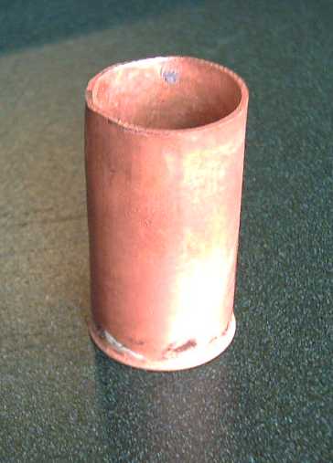
- poor performance testing continued - Trying to make a one-piece
copper can from copper pipe
The Everlasting Zinc Electrode: Why Am I Just Sitting On the
Gold
Mine?
I got the "everlasting zinc electrode" side of the
battery
chemistry working using bits of nickel [NiOOH] electrode from a
commercial Ni-MH dry cell for the other electrode - in fact quite
a
while back now. A zinc electrode that doesn't degrade with cycling
has
been a "holy grail" of battery making for at least 150 years.
Countless experiments have been done and dozens if not hundreds of
papers and semi-effective patents have been written on the
subject. And
most researchers have long since given up and looked for other
metals.
After that was going (using positive electrodes from
commercial Ni-MH cells), I started working on my "new
chemistry" positive electrode: nickel manganates. And at the same
time,
on making cells with higher conductivity than the experimental
flat
ones that couldn't stop the electrodes from bulging and losing
conductivity. I expected rapid success. But that hasn't come. The
nickel manganates formula just doesn't seem to be working the way
I
expected. (There are still more things to be tried!)
Finally I've started thinking, that whatever adverse
thing(s)
is happening in the positive electrodes, nobody else has managed
to
tame the zinc dendrite problem in the negative electrode for any
sort
of simple battery cell. Is that not already a success? Is it not
already worth a fortune?
The combination of an osmium doped film on the zinc
and a
layer of agar gel proved to be the winner. The agar layer prevents
the
vexing and previously intractable problem of dissolved zinc ions
forming dendrites that migrate through the separator sheet and
short
out the cell. But the current flow was pathetic. Painting the
osmium
doped acetal ester film on the surface of the zinc brings back the
high
current capacity zinc had before the agar. (I confess I don't
really
understand how.) The cell is "moderately alkaline" using potassium
chloride electrolyte or a mix of that and weak potassium
hydroxide.
 Since the time
I started experimenting with gels,
experimental gelled electrodes by others have now reputedly lasted
20,000 cycles without deterioration. This one too should last for
ages,
not just for the 500 recharges advertised in the one brand of
available
nickel-zinc "AA" cells I'm aware of. So why am I beating my head
over
trying to do entire batteries where I'm having trouble with other
parts,
while just sitting on the "mother lode"?
Since the time
I started experimenting with gels,
experimental gelled electrodes by others have now reputedly lasted
20,000 cycles without deterioration. This one too should last for
ages,
not just for the 500 recharges advertised in the one brand of
available
nickel-zinc "AA" cells I'm aware of. So why am I beating my head
over
trying to do entire batteries where I'm having trouble with other
parts,
while just sitting on the "mother lode"?
So the layers of the
negative part of the cell are:
1. Copper (or ?) current collector (copper can?)
2. The Zinc (suggested: Zinc paste in graphite foam or graphite
foil?
1-3% Zirconium silicate to raise hydrogen overvoltage.)
3. A film of acetal ester doped with osmium powder
4. A layer of gelled agar. I don't know how thick it needs to be.
I'm
thinking as little as an "eggshell" thickness could work.
5. The separator paper or sheet. Beyond that is the positive
electrode
and its current collector.
With 820 amp-hours per kilogram at about -1.25 volts,
zinc
has substantially better energy by weight than metal hydride. And
it's
cheap. In fact, typical construction single use manganese-zinc "D"
cells are said to hold 12 to 18
amp-hours (or even 20) depending on rate of discharge. (18 * 1.5V
= 27
watt-hours), whereas nickel-metal hydride "D"
cells only have 8 to 10 amp-hours (10 * 1.2V = 12 watt-hours).
Rechargeable nickel-zinc is nominally 1.6 volts (if not 1.7+), so
potentially 18AH * 1.6V = 29 watt-hours.
That means for a 12 volt battery 8 Ni-Zn cells (maybe
even
7) are needed instead of 10 Ni-MH, and it'll have over twice the
energy
storage. If (as is likely) the rechargeable cells weighed about
the
same as Mn-Zn single use alkaline dry
cells:
29 WH/D-cell (Ni-Zn) / .144 Kg/cell (typical Mn-Zn alkaline
D-cell) =
200
watt-hours/kilogram.
That is on a par with lithium-ion cells. Assuming 15
AH
gives 167 WH/Kg - still an impressive figure. In quantity it
would be much lower cost than either lithium types or nickel-metal
hydride - probably not a whole lot more than throw-away dry cells.
That
provides much potential for utility level electrical storage and
load
leveling. (eg, saving solar energy for evening cooking hours.)
So surely the "forever" rechargeable zinc electrode
formula should be worth a fortune all by itself! (So... now what
do I
do with it?)
Firewood Shed
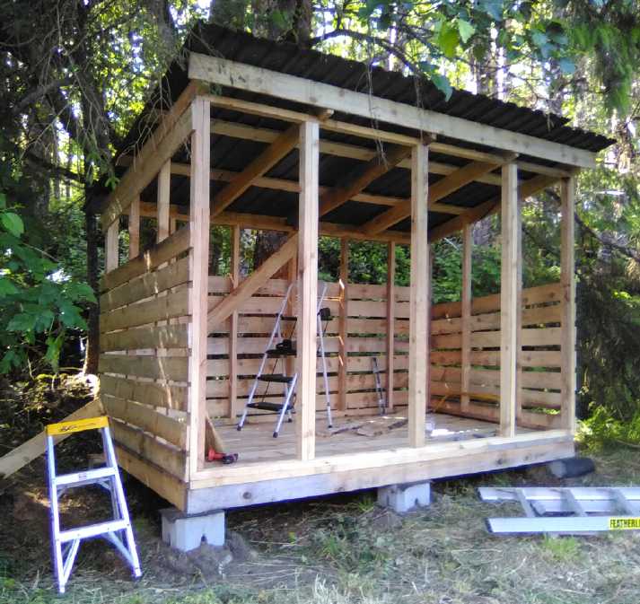 I
continued making the double sided firewood shed I
started in June. With just one firewood space, one ends up
stacking new
green wood on top and in front of the older dry wood. It wasn't
so much that I was enthusiastic about it as a project as that I
had
ordered 2 cords of firewood*. Next winter might be cold. I might
well
need it and I needed
somewhere to put it. Othen than things like some old metal roofing
and
concrete blocks, I used
entirely the spruce lumber I had cut with the handheld bandsaw
mill I
made in
2018, including one inch siding boards, which took
a lot longer to cut and screw on than plywood. But I put gaps in
the
siding for air
circulation to help the firewood dry out.
I
continued making the double sided firewood shed I
started in June. With just one firewood space, one ends up
stacking new
green wood on top and in front of the older dry wood. It wasn't
so much that I was enthusiastic about it as a project as that I
had
ordered 2 cords of firewood*. Next winter might be cold. I might
well
need it and I needed
somewhere to put it. Othen than things like some old metal roofing
and
concrete blocks, I used
entirely the spruce lumber I had cut with the handheld bandsaw
mill I
made in
2018, including one inch siding boards, which took
a lot longer to cut and screw on than plywood. But I put gaps in
the
siding for air
circulation to help the firewood dry out.
* In addition there's 2-1/2 cords now in the
original
firewood shed: a remnant from last winter and the rest variously
acquired, cut, split and stacked this spring and summer.
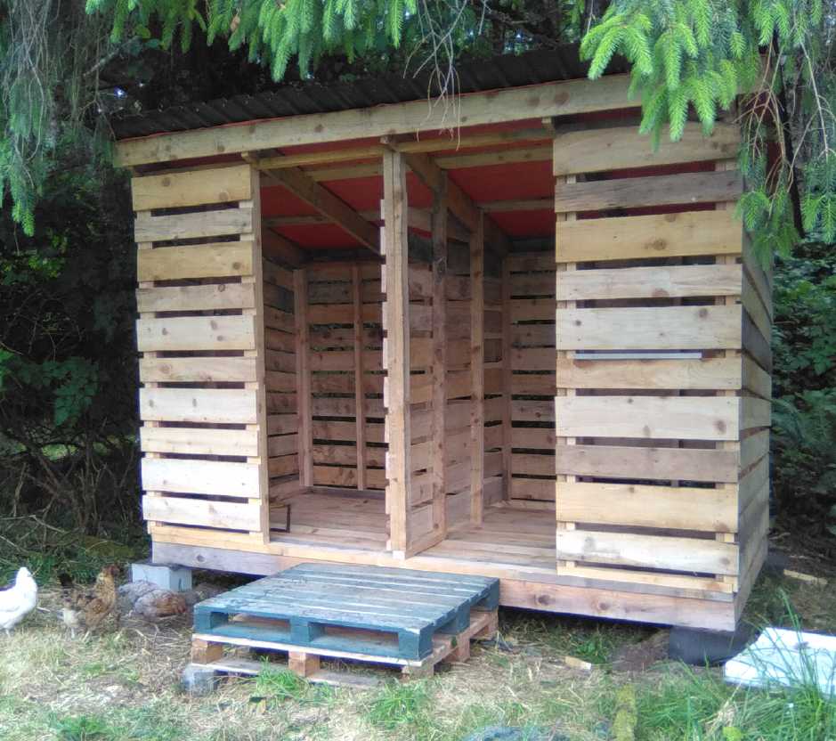 Shed finished except for the
doors. Prefab
front porch.
Shed finished except for the
doors. Prefab
front porch.
Each side holds almost two cords of firewood.
Escapee chickens came to see.
Of course the piles of
the
sizes of lumber I
was using (mostly 12 foot 1x6, 2x6) dwindled some, but it wasn't
1/5 of
the spruce I had cut with the handheld bandsaw mill in 2018 to
2020. I
finished it except for the doors, which are lower
priority. The firewood can go in.
The firewood arrived in three pickup truck loads on
the
31st. It got stacked before a day of wind and rain. A little
dampness
blew in the open doors, but not bad.
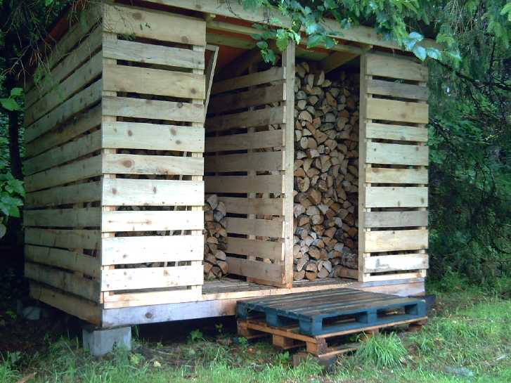 Expecting to be warm
whatever the
weather!
Expecting to be warm
whatever the
weather!
Vehicle Transmission
Efficiencies
I am guilty of not
having checked out information - "givens" I was operating under -
in a
long time and hence I have been working with outdated info. Back
in the
1970s(?) someone told me that manual car transmissions were about
70%
efficient, and automatics were around 60%. Four-wheel drives
(always
manual!) also lost an extra 10%, so 60%. (There was of course no
such
thing as an
internet back
then to readily check out information one has been given.) Those
rough
figures
were probably for the whole drive train. Probably they
were valid at the time, but there have been considerable
improvements
in recent decades, especially in the last 15 years or so, and
especially to automatic transmissions. Car companies certainly had
a
low bar to jump over for making improvements!
In some ways, automatic transmissions have an edge
because
they use inherently efficient planetary gears instead of two "corn
cobs" full of helical spur gears all churning and squeezing oil
through
the
gear tooth spaces by rotating against each
other at different speeds. These spur gears are all permanently
engaged
against each other, one fixed
to its shaft
and the other free-spinning, except the selected gear (only) is
locked
on both
shafts. The faster the engine is spinning, the faster the ones
fixed to
the input shaft are spinning, and the faster the car is moving,
the
faster the ones on the
output shaft are spinning. And these helical spur gears have
unproductive "side loading" forces causing still more wasted
fluid
friction to the oil on the bearings.
The killer for automatics was mostly the "slush box"
fluid
torque
converter. (How anyone conceived of churning up liquid as a way to
propel a vehicle is beyond me.) However, now those apparently have
a
clutch to lock them up and are no longer a loss in steady driving.
(This locking up
is similar to my concept for a 100% efficient variable torque
converter
but very differently implemented.) And evidently even these are
lately
being
replaced entirely by a "dual clutch" or even "triple clutch"
mechanism
(which items I haven't looked
up). And there have been other improvements to them as well:
electronic
controls, linked to electronic engine controls, adjusting
everything
together and shifting gears optimally. The result is that
automatic transmissions have become more efficient than manuals,
and so
manuals have become almost extinct.
Today's automatic transmission drive trains, it
seems, are
well over 80% efficient. An article mentioned 84%.
This doesn't change my essential thrust toward "ultra
efficient" electric motors and drive trains. The Sprint's simple
drive
train should be almost 96%. But I should at least be
more familiar with what else has been going on!
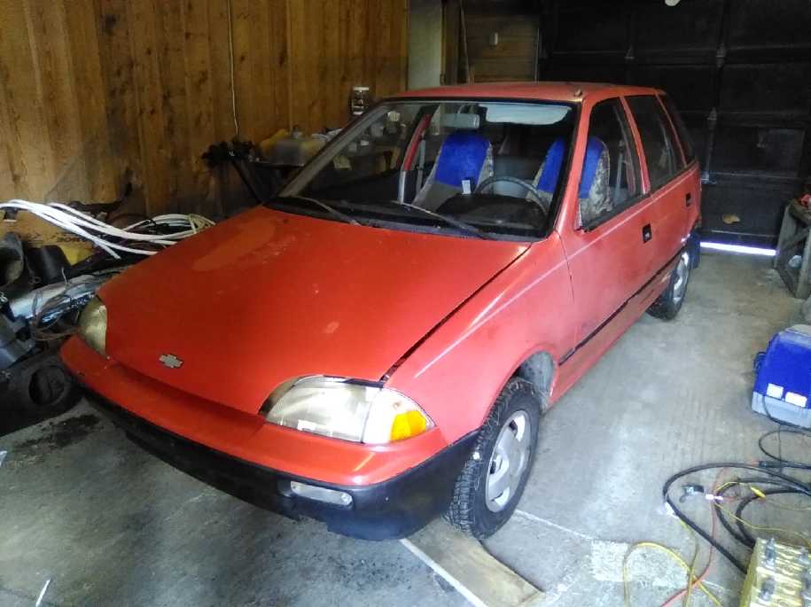
Chevy Sprint: Forward Reverse Switch, Bicycle speedometer
 With the
car
running and using it for odd hauling around
the acreage, and also for showing it to people, it was a nuisance
and
something of an embarrassment to have to push it to back it up. I
didn't
want to buy a costly high power DPDT contactor relay for a motor
that was (presumably) only temporary. But one day I made a special
high
current "DPDT" sort of switch and wired it in to reverse the
armature
coils polarity. It worked quite well (somewhat to my surprise),
and now
by yanking or shoving hard enough on the push-pull rod under the
dash,
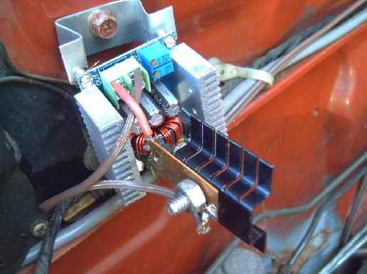
the direction can be changed. The copper pieces do get warm.
With the
car
running and using it for odd hauling around
the acreage, and also for showing it to people, it was a nuisance
and
something of an embarrassment to have to push it to back it up. I
didn't
want to buy a costly high power DPDT contactor relay for a motor
that was (presumably) only temporary. But one day I made a special
high
current "DPDT" sort of switch and wired it in to reverse the
armature
coils polarity. It worked quite well (somewhat to my surprise),
and now
by yanking or shoving hard enough on the push-pull rod under the
dash,
the direction can be changed. The copper pieces do get warm.
There was a notable "clunk" from the
motor supports the first time one presses the electron pedal after
reversing direction. (Motor assembly supports were revised on
August
4th to eliminate it.)
 Then on the 20th the bicycle speedometer I ordered
arrived, and I installed it. With the wheel jacked up in the
garage it
hit about 55 KmPH. Nice to see what the speed is, but on the
short,
bumpy trail across the lawn I only got it up to 25 KmPH. I
hesitate to
try it on the road. (If only it was a side street instead of the
main
highway!)
Then on the 20th the bicycle speedometer I ordered
arrived, and I installed it. With the wheel jacked up in the
garage it
hit about 55 KmPH. Nice to see what the speed is, but on the
short,
bumpy trail across the lawn I only got it up to 25 KmPH. I
hesitate to
try it on the road. (If only it was a side street instead of the
main
highway!)
In installing it, the tire circumference is measured
in
millimeters, and that number is entered as the setting to
calibrate the
unit. Here I realized in that that a figure I'd been roughly
estimating, "10 RPM for each 1 KmPH", can be exactly calculated.
The
Sprint's tires measured about 1670mm in circumference. That can
also be
expressed as .001670 kilometers. 1 / .00167 = almost exactly 600
revolutions to travel 1 Km. So with 60 minutes in an hour, 1 KmPH
is
almost exactly 600 / 60 = 10.0 RPM. My rough estimate was closer
than I
ever suspected!
(I've ordered an identical speedometer for the Miles
truck.)
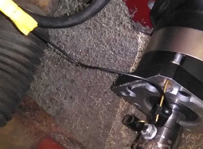 Speedometer Sensor: Magnet
spinning on CV shaft
coupler,
Speedometer Sensor: Magnet
spinning on CV shaft
coupler,
Magnet sensor hanging from planetary gearbox is wired to
speedometer on
dash.
(Gosh, wouldn't it be nice to enclose under the entire hood area
to
keep rain & rocks out?)
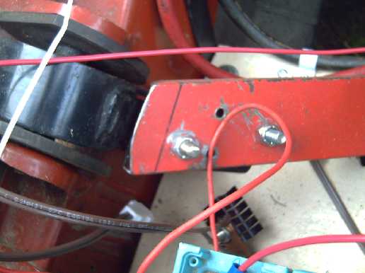
 A friend
came
along one day and looked under the hood
while I drove back and forth a bit. He showed me by pulling on it
how
much the motor assembly was rotating under torque pressure, and
the
"clunk" backing up was something hitting the edge of the battery
shelf.
I also noticed there was a simple way to improve it with a short,
fat
steel "L" bar to another spot on the plate, making the connections
form
a triangle instead of just a line and holding the rear
rubber-cushioned
support itself at the right angle.
A friend
came
along one day and looked under the hood
while I drove back and forth a bit. He showed me by pulling on it
how
much the motor assembly was rotating under torque pressure, and
the
"clunk" backing up was something hitting the edge of the battery
shelf.
I also noticed there was a simple way to improve it with a short,
fat
steel "L" bar to another spot on the plate, making the connections
form
a triangle instead of just a line and holding the rear
rubber-cushioned
support itself at the right angle.
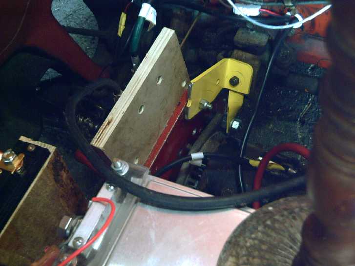
Much better, but even after all that there still
seemed to
be a "clunk"! My friend was over again and looked in. It seemed
the
rear cushion support was still tilting with torque, and the rubber
cushioned part was
hitting an end stop in reverse, so the metal parts connected -
clunk.
(BTW the wooden spindle and base on the right is the lamp.)
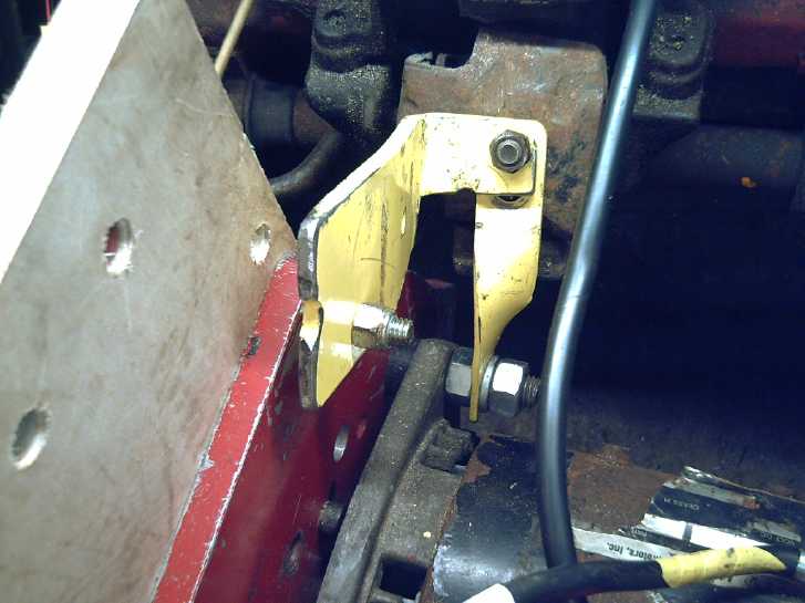 [August 4th] I looked
at
the original transmission bracket and saw it
had held the rear cushion mounting at about 45°. Mine was pulling
it over to more like 70°, nearer vertical.
[August 4th] I looked
at
the original transmission bracket and saw it
had held the rear cushion mounting at about 45°. Mine was pulling
it over to more like 70°, nearer vertical.
I disassembled the rear mount pieces. I drilled new
holes
and bent the pieces to sit at a
better angle on the mount.
If it didn't end up at the "ideal" 45° slope, it
was at least closer to 50° than 70°.
That seemed to eliminate the main "clunk". There was
still
a smaller, sharp "tink", always just once after changing from
forward
to reverse and pressing the pedal. I guessed it was something in
the
drive shaft, but found nothing. Perhaps
this remaining "tink" is in the actual CV joint, or something in
the
suspension? It hardly seems worth further investigation.
Lithium Ion Battery Charge Voltage
For some reason after putting the Sprint on charge I
looked this up again. I wondered why people were so insistent
about
charging to the absolute limit voltage of 4.2 volts per cell if
3.95
volts was virtually a full charge. It's so important not to exceed
that
limit, and some cheap voltmeters, for example on the charge
controller,
aren't all the precise. I get readings from "39.0" to "39.7" from
different displays at the same time. It's nice to have a safety
factor.
But it appears that I may have been looking at a
battery discharge
curve graph rather than one of open circuit voltage, and
charging to only 3.95 open circuit volts per cell could after all
be as
little as 80% of the full charge potential. OTOH, if one doesn't
need
the full capacity, charging to a bit less than 100% full is likely
to
extend the life of the cells. If I need the capacity I may up the
charge voltage. That might be if the Sprint goes on the highway,
or if
there's a long power failure and I'm having trouble running
fridge,
freezer and lights overnight from its batteries.
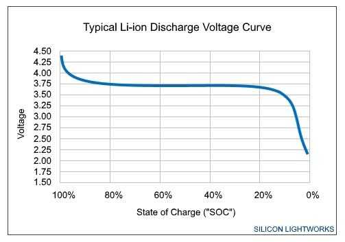 The voltages in a discharge
graph will
be lower than the open circuit voltages.
The voltages in a discharge
graph will
be lower than the open circuit voltages.
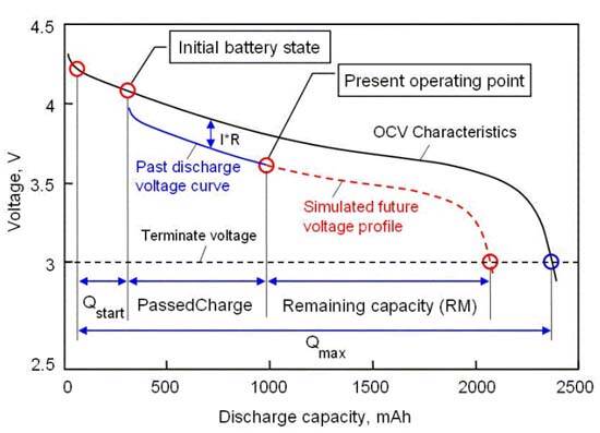
A graph showing both open circuit voltages and discharging
voltages.
(of course the heavier the load, the lower the discharge voltage
will
be.)
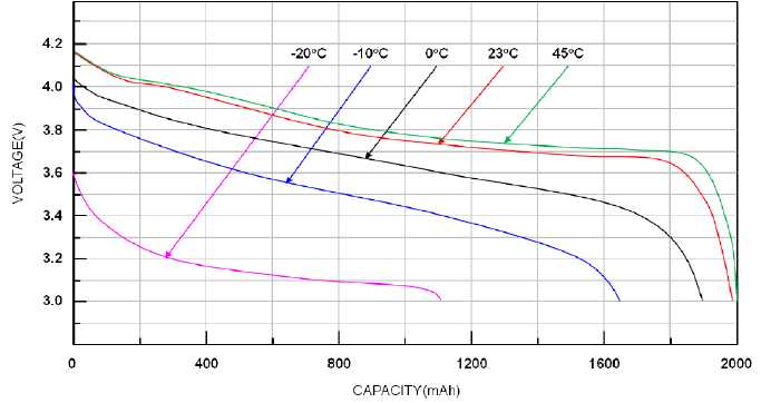 But lest it all seem too cut
and
dried, the
voltages (seemingly open circuit voltages)
But lest it all seem too cut
and
dried, the
voltages (seemingly open circuit voltages)
also change markedly with temperature.
(which shows one factor decreasing vehicle energy economy in
cold
weather - and
another reason to leave a safety margin! 3.95V is evidently 100%
charge
at
-10°C!)
---
On the 16th, the middle of the month having come, I started
thinking
about my project priorities.
* Firewood shed was almost finished to the point where it could be
filled with the firewood
* Cabin hadn't been worked on since early May
* Ground effect craft just needed some more programming before
trying
to fly it.
* The new chemie battery was about dry enough to try adding some
salt
electrolyte.
* The bandsaw mill kit idea seemed to have fallen by the wayside
for
some time.
* So had documenting how to make my Supercorders.
* And then there's assembling the third li-ion battery stack. That
would be what was needed to run the truck at this point.
The list could go on and on, but that was already too
much
to even think about!
I figured a couple of good programming sessions for
the
craft, but it might easily stretch into a week. Could I work a few
battery tests in somewhere? Then the bandsaw mill kit, which might
bring in some revenue, beckoned.
By the end of the day the firewood shed was in
operating
shape. It still needed one piece of wood put up and doors. Then it
should keep raccoons out unless they can squeeze through a smaller
gap
than I think. In the evening for the first time in a while, it
really
rained. No sign of "wet" anywhere inside or around the walls,
except
just inside the open doorways. As it seems to be staying "wettish"
out,
I finished just in time. I know the seller has the
firewood outside, now getting wet. Time to get it delivered!
By the 26th somehow all I had done was another
programming
session on the craft (and then decided it should be done a
different
way) and tried out the salt electrolyte in the battery with my
typical
disappointing results, along with trying to make a one-piece
copper
battery can from copper pipe.
But that's when I gave it some more thought and
realized
that since I already had the really significant result, an
everlasting
zinc electrode (as I wrote about above), perhaps concentrating on
the
frustrating nickel-manganates positive electrodes that just
weren't
cooperating was rather a waste of my time and I should drop the
battery
work.
---
Below to end are a couple of interesting sustainable
power
projects people have pointed me to this month. There was a video
somewhere on Youtube about the Qinghai solar installations. Later
I
located
satellite images of them via Google Maps.
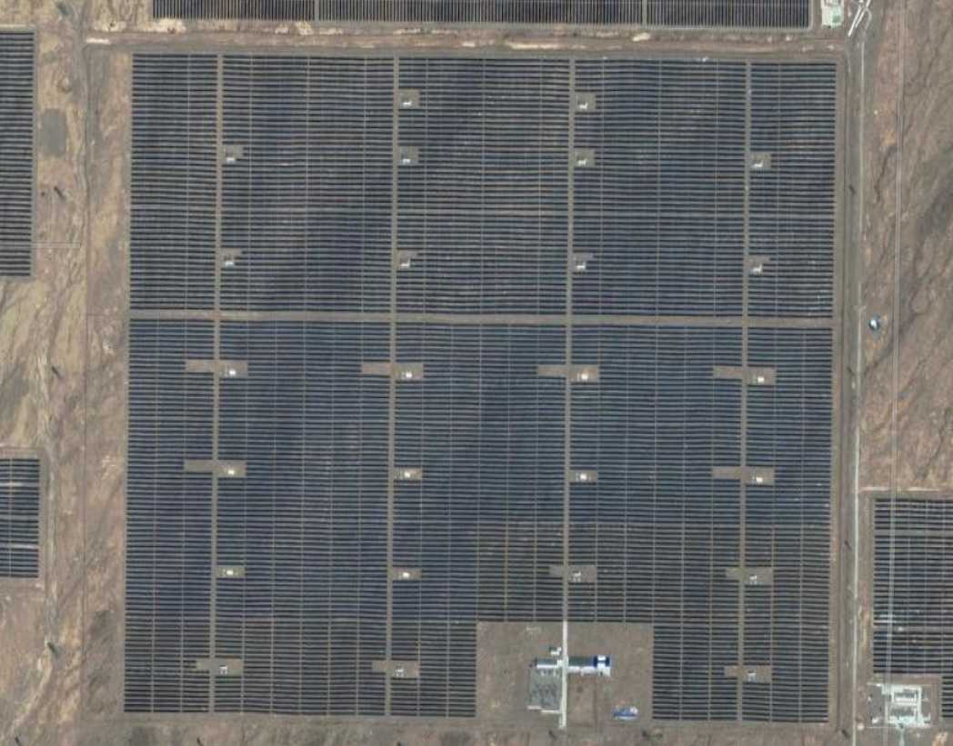
Solar Installations in Qinghai
Here are a few [Google Maps] satellite images of
stupendous Chinese solar power installations - in a northwestern
desert
in Qinghai [southeast of Shingjiang (or Xingjiang, AKA East
Turkestan)]
at about 37.3° north. The area of the broad view is about 17-1/2
Km
by 7-1/2 Km.
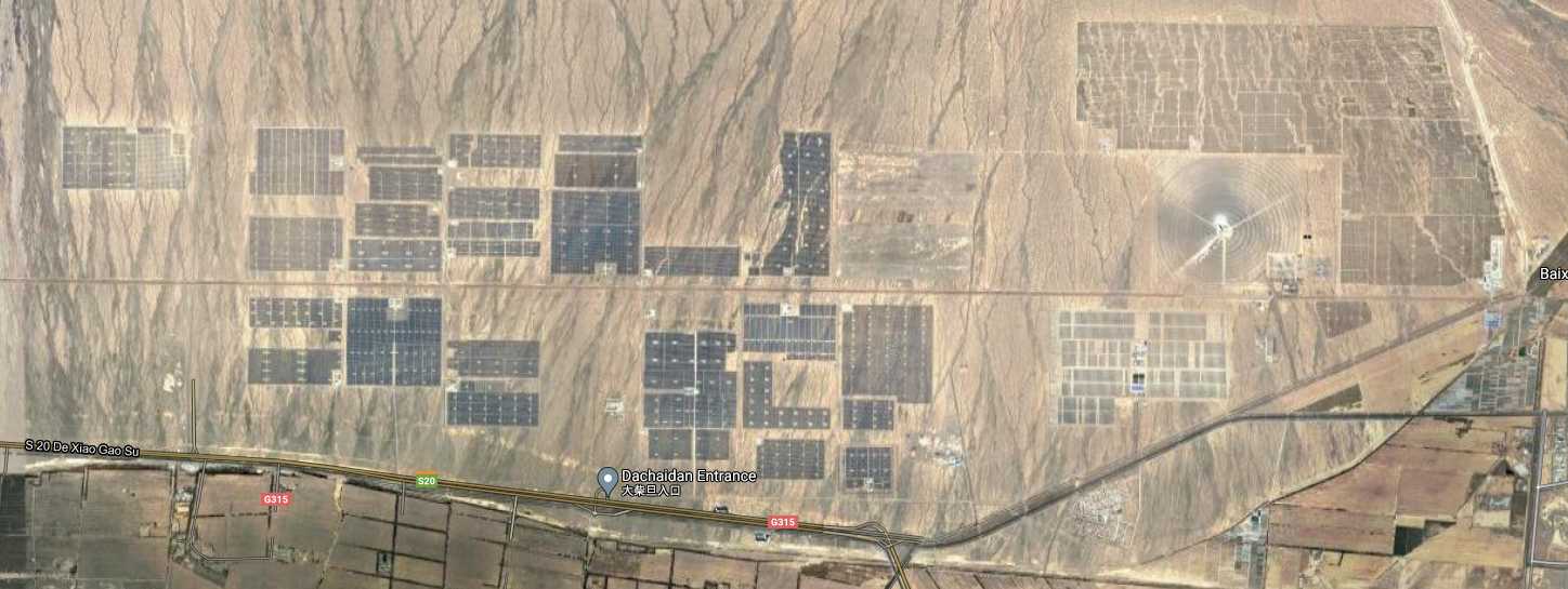
These apparently supply much of the power for the
entire
region. They wash off the panels (monthly?) and the water plus the
shade from the panels has caused vegetation to grow, which started
to
grow over the panels. So they got a rancher (multiple
ranchers?) to graze sheep in the installations among the panels.
The
rancher interviewed thinks it's marvelous: win-win!
Each tiny black strip below is a row of about 16
solar
panels (hard to count at any scale). If that count is correct,
there
are 768 one meter wide panels from left to right. There seem to be
almost 60 rows, which would be 46,000 solar panels in this one
field.
If they were 300 watts each, that would be over 13 megawatts
rating.
(Over double the BC Site-C dam project, IIRC, from this one
field.)
While most fields go
east-west to get the maximum daily collection, a few fields have
rows
oriented north-south, surely to maximize evening (supper cooking
time?)
or early morning collection.
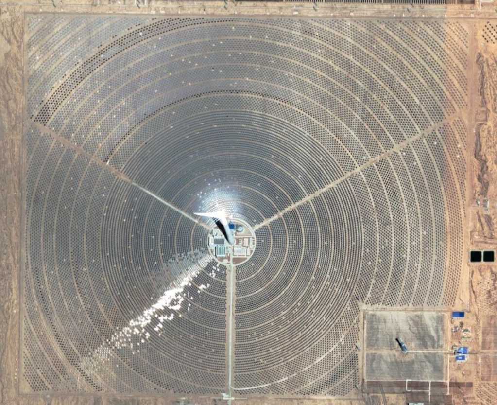
Below is a solar concentrating collector (near the right
end of
the broad first image). Typicly in such installations, mirrors
direct
sunlight to a concentrating point at the top of the huge central
tower,
where steam is made to run a steam turbine generator. The mirrors
have
to automaticly move continually to maintain their aim over the day
and
through the seasons. With the falling price of solar PV panels
this is
complex system is probably an obsolete idea. (I understand they're
also
good for frying passing birds.)
(The small tower at the lower right may have been the
"proof of concept" prototype installation?)
Another Floating Tidal Flow Power
Unit
This Sustainable Marine Tidal System tidal
power
unit from Nova Scotia seems unique in using multiple
smaller propellers, which should make it usable in much shallower
waters than the 'two huge propellers' Orbital Marine ones in the
Orkney
Islands. It looks like it could be a winner. They might be just
the
thing for Masset inlet on Haida Gwaii. If they don't chop up fish.

 One trusts that each
propeller/generator can be
raised, removed
One trusts that each
propeller/generator can be
raised, removed
and serviced individually without it being a really major
operation
In
Passing
(Miscellaneous topics, editorial comments & opinionated rants)
Food
Security:
A
Constitutional
Right
to
Grow and Trade Food
Here is the summary of a declaration recently
proposed in
the State of Maine, USA, legislature.
"Section 25. This constitutional resolution
declares that all individuals have a natural, inherent and
inalienable
right to acquire, produce, process, prepare, preserve and
consume, and
to barter, trade and purchase the food of their own choosing
for their
own nourishment, sustenance, bodily health and well being."
(The full statement continues with provisos to exclude unlawful or
harmful acts to acquire food. It also contains a phrase that says
everyone has the right to
eat well, which is likely to be proven unattainable in the next
few
years. - still the whole act is all in one sentence!)
It seems to me that such a declaration enshrined into
a
constitution or bill of rights would go a long way to correct
legal
imbalances that in many subtle or coercive ways favor the mass
production and centralized distribution of food by a small number
of
"mega" corporations, which block individuals and families from the
potential of making their own local food for their own locality.
This
impoverishes rural communities financially and increases
vulnerability
of the food supply everywhere.
That such a thing is happening may be puzzling to the
majority. Can we not plant and harvest our own vegetables? (Even
this
seems to be under threat these days!) But garden produce is not
the
only food group. I will revert to a couple of examples I've
mentioned
before.
* Milk Products Ostensibly to protect public health,
in
the early 1970s BC outlawed sale of raw milk. Furthermore,
pasteurizing
milk had to be done at a government inspected facility where it is
done
in vast quantities in programmed processes with chart recorders
available for government inspection.
The result was predictable: One cow produces too much
milk
for a single family, and is too much work and expense to keep one
just
to throw out most of the milk. So the entire rural population all
across BC had to get rid of their dairy cows. Family producers all
over
the province were prevented from earning local income from their
cow or
small herd. I recall this being enforced against a family who was
selling us delicious raw milk in 1972, from which we were also
making
butter and ice cream. Today as far as I know there are only a
handful
of dairy cattle in all of northern and rural BC, mostly owned by
Mennonites. All our milk is shipped from 2 or 3 big processors in
the
big cities, across the entire province, and the processed milk
can't be
made into butter, cheese, sour cream or buttermilk - making
everyone
still more dependent on the "factory" dairy processors. And of
course,
the dairy farms are clustered around the big cities near the
processing
plants. One presumes that the cattle herds are much too
concentrated to
graze on their own pastures and so feed must be grown and
processed
here, there and everywhere, then purchased and transported in.
This,
instead of grazing the cattle on that land to "harvest" and
"process"
it themselves, with more local and direct distribution of the end
product. From an economic standpoint, what makes more sense?
As far as public health is concerned, all the
transported
product is less fresh. I occasionally get migraines from milk
direct
from the store on the day I bought it (less often than I used to)
and
have to take a migraine pill, dump the whole gallon of one cup
serving
bottles I've just frozen, and re-wash the bottles. And I
understand
that while there have very occasionally been hospitalizations owed
to
raw milk products, there have been no deaths at all in modern
times. Is
that sufficient health concern to prohibit what people have done
for
thousands of years? Even if one considers raw milk unsafe, there
are
now economical counter-top milk pasteurizers, and doubtless there
would
be many more and better choices if there was a legal market for
them in
larger countries.
* Meat At some time (probably also in the 1970s), it
became a requirement that domestic meat be butchered only at a
registered government facility. A small grocer I knew in Victoria
BC
used to butcher his own and always had fresh meat. You could buy
your
week's groceries there. He closed the meat section and gradually
the
selection of everything shrank. They sold lottery tickets instead.
On
this island I'm told Richardson Ranch used to butcher grass fed
cattle
annually in the fall. Now the cattle must be trucked to a facility
on
the mainland (just the long ferry ride costs hundreds of dollars
and a
round trip takes several days), butchered doubtless by others for
which
the ranch must pay instead of earn, and then (hopefully) the meat
is
shipped back to the island. How is it that the amateurs who
butcher
their own deer meat are no longer permitted to trust the
experienced
ranchers to sell them beef they've butchered?
A key word missed was "sell". One has the right to
buy
food, and to barter or trade it for one's own use, but not
necessarily
to sell it outright to others. That was probably as far as the
proposer
of the amendment wanted to or dared to go. Still, if the things
listed
were considered to be "rights", it would be much harder to argue
for
monopolistic food industries and against local food production and
distribution, and laws such as these examples that shut it down by
making local production and sale impractical or uneconomic might
start
to be thought of as government overreach and would be much harder
to
argue for.
Small
Thots
* Obviously my little gardens even with
the no-fruit problems are doing better than a lot of commercial
farming
right now. Practicly every major wheat exporting country's crops
are
way down this year. Droughts, floods, locusts, mice...
With corn and soy production down so much in the last
couple of years, meat producers have been switching to wheat to
feed
their herds. Now that too is becoming prohibitively expensive and
and
the remaining choice is to drasticly reduce the herds so they
don't
starve outright. And the supply
chain is having
problems delivering even what there is. Ukraine has wheat but
can't get
it out to export.
Railroads in the US west are shutting down because they're afraid
of
potentially starting yet more forest fires. Every year the
situation
looks worse than the year before, and we must be getting close to
some
tipping point.
* Some in the grocery business are commenting under youtube videos
that
warehouses are looking rather spacious, grocery store orders are
being
short shipped owing to shortages and some products are becoming
hard to
get or have been discontinued. This has in fact been a growing
trend
for a year or two now. Some are even worried about August; some
think
things will last until after Christmas. Is it all just
fearmongering?
Where in the world is there any big
breadbasket of crops growing "as usual" this year?
* I just ran across a French word: "Liberticides" - killers of
liberty.
In my meager understanding of French it usually seems to be
applied to
what are considered to be unjustified authoritarian laws and
edicts.
According to an online translator "Liberticide" is an English
word,
too, but I'm not sure the translator actually knows what it means,
or
if it's just copying an unknown word straight into the [one word]
translation. It seems an apt word to describe some things that
have
been happening.
 * In a
today typical piece
of oligarchic corruption, a former head of Telus, a monopolistic
telecomm company with a corporate culture of greed, fraud and
deceit
was appointed head of the Canadian Radio and Television Commission
(CRTC), the federal government agency assigned as the watchdog
over
such companies. (He seems to have ordered things done to enrich
Telus
for which a private citizen would have gone to jail.) This is of
course
having a wolf for the shepherd. Canadians pay more than any other
people for our telephone, TV and internet services, and rules are
rigged to keep other service providers out.
* In a
today typical piece
of oligarchic corruption, a former head of Telus, a monopolistic
telecomm company with a corporate culture of greed, fraud and
deceit
was appointed head of the Canadian Radio and Television Commission
(CRTC), the federal government agency assigned as the watchdog
over
such companies. (He seems to have ordered things done to enrich
Telus
for which a private citizen would have gone to jail.) This is of
course
having a wolf for the shepherd. Canadians pay more than any other
people for our telephone, TV and internet services, and rules are
rigged to keep other service providers out.
Someone recognized him in a bar, having a beer with
the
CEO of Bell, a telecomm company with an even worse reputation. We
can
be pretty sure he wasn't "laying down the law" to Bell but rather
they
were plotting together how to continue to keep competition out and
extract still more money from Canadians. The organization OpenMedia
has called him out on it in a full page ad in the capital's
newspaper,
the Ottawa Citizen.
If he doesn't respond favorably I hope they ask the
government to fire him and suggest a replacement. Can the corrupt
be
ousted without pitchforks and torches coming out? That's not
supposed
to be necessary in a democracy - of course, such people should
never be
considered for holding a position of public trust in the first
place.
ESD
(Eccentric Silliness Department)
* In any court case there are two sides: the Defense and the
Persecution.
* A good Offense requires the best Defense - or the offender will
be
persecuted.
* The bank lacked liquidity, so we dug a trench around it and
filled it
with paint thinner. Now it's just another insolvent bank.
* Orders of magnitude as applied to financial currency: one -
thousand
- million - zillion - gazillion - quazillion ...
* A typical bungalow worth a million dollars today may be worth a
gazillion by this time next year.
* A quazillion dollars in 10,000$ bills would stack to the moon
and
back.
* Food worth 100$ today may be 10,000$ by this time next year.
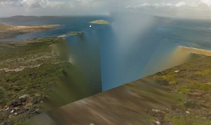
* It was once feared one could sail off a waterfall over the edge
of
the world. That was dismissed as ignorance, but I recently found
this
Google 360° photo image that proves it's real. (Apparently one
edge
of the
world is in the West Falklands):
* I bought a bag of rock wool insulation to have on hand for when
I
(theoreticly, some day) get around to making my plastic sheet
press,
which will (I hope!) probably get too hot for fiberglass. What I'd
really like to know is, how do they fleece the rocks to get their
wool?
:( All the rocks I find are already fleeced. ):
* Once spawn has been spawned, doesn't responding just increase
the
quantity?
* Burrito: A baby burro
"in depth reports" for
each project are below. I hope they may be useful to anyone who
wants
to get into a similar project, to glean ideas for how something
might be done, as well as things that might have been tried, or
just
thought
of and not tried... and even of how not to do something -
why
it didn't
work or proved impractical. Sometimes they set out inventive
thoughts
almost as they occur - and are the actual organization and
elaboration
in writing of those thoughts. They are thus partly a diary and are
not
extensively proof-read for literary perfection, consistency,
completeness and elimination of duplications before
publication. I hope they may add to the body of wisdom for other
researchers and developers to help them find more productive paths
and
avoid potential pitfalls and dead ends.
Electric
Transport
Ground Effect
Craft
(R/C Model)
[8th] I had been wondering
about the methods for programming and testing the combination
motor
thrust/steering controls. Turning my attention to the project
again at
long last, it occurred to me that instead of trying to get it all
working at once, I could check the motor outputs by simulating the
received radio control joystick commands with the
display-controller
buttons. The lower two left and right buttons could slew the
steering
"joystick position" to the left and right, while the two vertical
ones
in the middle could be throttle up and down. They would directly
increment/decrement the "ThrottlePosition" and "SteeringPosition"
variables, each 0 to 15, and the display would show the number. As
I
wrote the code I thought to do a "STOP" button too, that
immediately
turned off the motors and set 'steering' to center.
Then the output variables, the strange PWM signals
that
the receiver puts out, would be fed to the motors to hopefully
give the
desired effects, and everything tweaked until the motors ran
right.
Then the receiver end could be implemented and feed
the
same two variables and the display with the motors off, and
finally the
two could be coupled together when they both seemed to work well.
[9th,10th] I spent especially the day of the 10th trying to get
just
the pushbuttons to work. It was frustrating dealing with somebody
else's assembler and debugger instead of all the fabulous software
development tools I had made for myself in the 1980s and 1990s,
but
which aren't applicable to the new microcontrollers. The biggest
problem turned out to be the weird syntax of the "call" (AKA
"jsr")
instruction. One expects "call readbuttons" to do just that... but
no,
it's "call #readbuttons". Without the "#" it defaults to some
strange
address mode that no one would use and goes off into space, and I
forgot about that in a couple of places. Then the obtuse debugger
made
it difficult to track down the problem. But finally it worked and
the
numbers slewed up and down happily.
[17th & 20th] (Still can't seem to get to this in any hurry!)
The
model aircraft radio control signals are supposedly 1.0 (full off
or
full left) to 2.0 (full on or full right) milliseconds, in a fixed
period of 50 Hz (20 milliseconds). All very vaguely specified.
My original intent had been to have timer interrupts
to
make the output pulses to the motors be between 1 and 2
milliseconds
per these requirements, with the second half of the pulse length
divided into 16 parts, "off" to "full on". But it finally dawned
on me
that to divide a millisecond down into 16 parts would mean an
interrupt
every 67 microseconds. I hadn't paid any attention to the
processor
speed, but it was megahertz rather than gigahertz and I figured
that
such a frequent interrupt wasn't "going to fly", so to speak. It
would
have to be done another way.
I programmed "Timer A" and got its interrupt working,
but
only every 20 milliseconds for the 50 Hz, not every 67
microseconds. To
determine the speed I divided it by 50 to have a light blink on or
off,
adjusting that to once per second. I found that running Timer A
from
the fastest internal clock and dividing by 1 (instead of 8), it
only
counted to 120 to give the 20 mSec. I had expected a much larger
number. (A 67 µSec count would be to less than one - not even
possible!)
I decided to use a simple program delay timing loop
in the
main
event loop with a register counting down to get the 67 µSec
intervals. This would be triggered every 20 mSec by the timer. The
control pulses could be up to 2 mSec occupying 10% of the total
time.
This was obviously going to have to interact with the 1 to 2 mSec
receiver pulses that might (inevitably) happen concurrently. Oh
well,
one thing at a time.
[26th] I was thinking about the asynchronous nature and critical
timing
of the signals from the receiver while the equally critical timing
loops for the transmitter were running. A new strategy came to me.
There was 2 milliseconds of receive signal and 2 of transmit. But
the
period overall was 20 milliseconds. That's 16 idle seconds. What
if I
simply waited for the receive signal, decoded its length from 1 to
2
milliseconds, and then, knowing it had already occurred, there was
plenty of time to send a 1 to 2 millisecond pulse to the motors,
and
then to do anything else necessary, before the next receive
signal. The
only thing I didn't know was whether the up-down pulse was
synchronized
with the left-right pulse or if they occurred randomly (which
would
throw a monkey wrench into things), or if they were synchronous,
whether they were at the same time or occurred at different times.
The
only way to tell that would be to view the waveforms on the
oscilloscope. (Ug!) As long as they're not asynchronous with each
other
any timings can be accommodated.
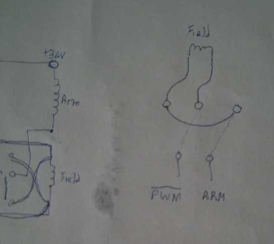
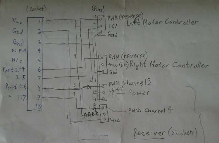 I'm copying my wiring
diagram
into this
newsletter for myself, before I lose the piece of paper.
I'm copying my wiring
diagram
into this
newsletter for myself, before I lose the piece of paper.
(The socket on the left is on the microcontroller board. The
ones on the
right are to the motor controllers and from the radio control
receiver.)
Chevy Sprint
Add-ons: Forward-Reverse, Speedometer
And at some point I had sprayed the pivots of the
windshield wipers with WD40 or something. When I thought to try
them
maybe a week later and beyond, they started wiping more easily. On
"high" they started going faster instead of slower. I didn't see
any
smoke from the controls, although I haven't dared leave them on
for
very long. (But one day it was raining and I actually had to use
the
wipers! I put in some windshield washer fluid and that worked,
too!)
---
 [12th] There were some
little details yet to go on the car. First, I
moved the 12 volt charging plug arrangement so the isolation diode
was
on the
battery terminal instead of hanging perilously in mid air on a
wire by
the DC to
DC
converter. (Oops, no "after" picture?)
[12th] There were some
little details yet to go on the car. First, I
moved the 12 volt charging plug arrangement so the isolation diode
was
on the
battery terminal instead of hanging perilously in mid air on a
wire by
the DC to
DC
converter. (Oops, no "after" picture?)
But the big thing was
reverse. It seemed a bit silly
having to get out and push the car to back it up. In fact as I was
actually using the car (if only for hauling lumber and things
around
the acreage), it was getting to be a nuisance. And a bit
embarrassing
to
"proudly" show the novel, smooth-running car to people and yet
have to
do that.
To reverse direction on a series wound DC motor, one
must
change the polarity of the field coils without changing the
polarity of
the armature coils, or vice versa. Simply changing that of the
entire
motor won't reverse it. And the field coils have the same high
currents
flowing in them as the armature coils.
As I don't intend to use this motor long term, I
didn't
want to spend
probably hundreds of dollars on a big DPDT contactor relay - or
even
order and wait for a probably cheaper one from China. But perhaps
I could make a heavy duty version of a DPDT "knife switch" with
some
lever on the dash to flip it. To handle the currents: thick copper
plate switch arms, and copper water pipe shaped into clips to
connect
to. Or maybe it could be a slide switch? I decided on a special
flat
switch on a plate of plywood.
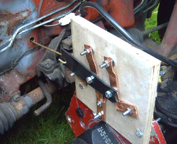
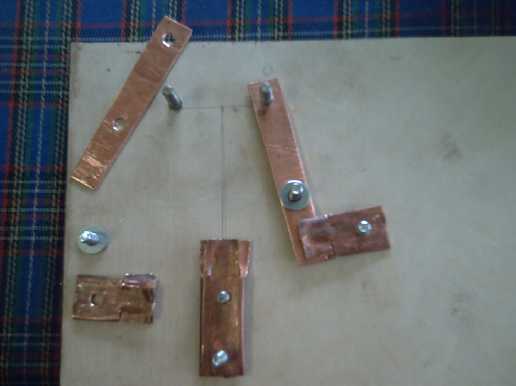 Okay, 6 bolts sticking up
through
the plywood,
heads all recessed (using flat blade drill bit).
Okay, 6 bolts sticking up
through
the plywood,
heads all recessed (using flat blade drill bit).
* Two flat copper bars pivoting in unison on bolts.
* 3 contact "clips" of copper water pipe.
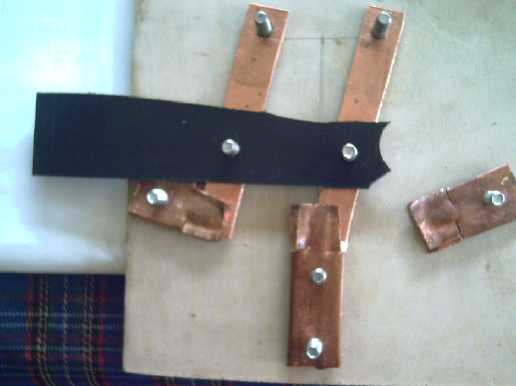 Delrin plastic to couple the
two
moving bars.
Delrin plastic to couple the
two
moving bars.
Mounting it on the motor
plate
under the hood.
Brass push-pull rod to "flip" the switch goes into the cab.
(inner end recessed, on passenger side of center hump.)
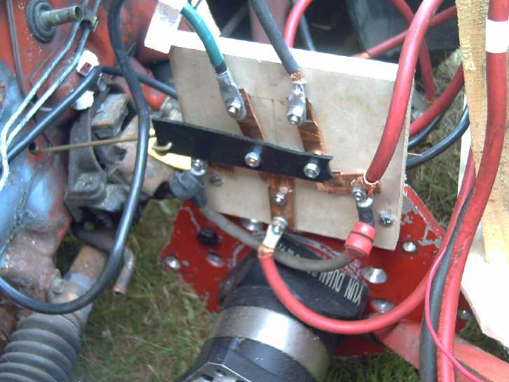 It was "sort of" DPDT. It did what DPDT switches are usually
wired to do: reverse the output connections when flipped. Two
moving
bars
connect to the two input wires. There are three roughly formed
output
"clips". The
center one connects to one bar in forward and the other in
reverse, and
powers one end of the field coils. One or the other of the end
ones is
connected to
a bar, to the bar not then connecting to the middle. The two end
clips
are
tied together and go to the other end of the field coils.
It was "sort of" DPDT. It did what DPDT switches are usually
wired to do: reverse the output connections when flipped. Two
moving
bars
connect to the two input wires. There are three roughly formed
output
"clips". The
center one connects to one bar in forward and the other in
reverse, and
powers one end of the field coils. One or the other of the end
ones is
connected to
a bar, to the bar not then connecting to the middle. The two end
clips
are
tied together and go to the other end of the field coils.
The bars have to move together but they can't be
electricly connected. I used a piece of delrin/acetal plastic as a
tie
bar with a protruding end to pull/push on.
At the car I noticed that if I mounted the switch on
the
motor/gearbox plate, I could arrange it so a push rod could go
through
an existing hole in the firewall, which I could reach to "flip"
the
switch from the driver's seat. (It was once the hole for the gear
shift
lever cable.)
I had it done that day and tried it out. It's not
elegant;
in fact pretty "makeshift", but it does seem to work if one pushes
and
pulls hard enough on the rod.
Then I drove it across the acreage. One bar on the
switch
got hot, the
other only warm. Backing up (starting with a clunk!), both bars
got
hot. Now I didn't
trust
driving it. Maybe I could file inside the clips to clean the
copper,
and bend them for a tighter grip? (It was running fine without a
switch... maybe I should have left well enough
alone?)
Later I brought a small file and looked again. I
discovered that one of the bolts holding a wire to its bar was
loose.
(I had checked them all before I started it up, honest!) I
drove around again. In a little backing up, nothing got hot. After
a
"fast" (read, "bouncy") drive with high currents going up the
hill,
both bars were a little
warm, but nothing was hot.
Let's see... The bars
were
~1.7mm thick by 16mm wide, or
27 square millimeters. If it was round wire:
Area = π * R^2, so R = √(Area / π)
√(27 / π) = 2.93 mm. (diameter 5.84 mm)
That would be about #3 AWG. The wires are #2 or #4,
so
that's a pretty good match. The heat must be from contact
resistance at
the connections between clips and bars when carrying 50 to 100+
amps.
But they were just warm, not hot like with the loose wire.
Considering
the roughly shaped copper contact pieces of the switch, it's
surely to
be expected. I guess everything is fine. I'll continue checking it
after driving.
And I must fasten the heavy wires down properly so
they
don't rub on anything and gradually wear off their insulation.
Maybe
even cut some shorter ones, since they're all substantially longer
than
they need to be.
I was glad to have started and essentially finished
this
project and written it up in one day. In retrospect rather
surprised.
Things that could have been time consuming like the switch design,
mounting the switch, and a way for the driver to operate it, just
fell
into place and it went amazingly smoothly. In spite of starting
with
somewhat vague ideas, nothing was puzzled over for long, and
nothing
was done that had to be undone or redone or done differently. I
don't
suppose putting in a
commercial contactor relay would have taken less time. I'd
have had to wire up power to activate it from a switch on the
dash.
(Could I even have found an appropriate one, heavy DPDT contacts
and 36
volts DC activated? or perhaps 12 V DC?)
---
I've found some of the beeps and whistles of the
Nissan
Leaf annoying (especially chiming away continually when I get out
to
open and close the driveway gate), but I'm starting to see their
utility, because I've already got out and walked away without
turning
the Sprint off a couple of times. (Only for short periods... so
far! Of
course it's not something you'd do with a petrol car.) Maybe I
actually
should install some annoying reminder beeper for when the door is
opened with it running. (Hmm... easier to do if the driver's door
switch was working. If the door is open for enough weeks, the cab
light
comes on. How do I get at that switch?)
[13th] I had a look. A plastic panel unclipped easily. When I had
it
off I discovered that the whole switch could just be pried right
out
from outside! It consisted of just one wire that connected to the
clip
that held the switch from falling out by itself, which was also
supposed to
connect to the car body. Corrosion presumably had stopped it. I
worked
it around a bit until it connected.
In that I discovered that the car already had an
annoying
beeper when the door opened and the key was in the ignition, or
the
lights were turned on. That solves that!
---
 There
were
nasty clunks when changing direction. I thought this must be the
hollow
rectangular
tube motor mount strut. One can't do up the bolts very tightly on
flat
tubes - they
simply
start to crush the tube. (I had used locking nuts to ensure they
wouldn't
gradually unwind.) So with the reversing torque the bolts were
probably slipping up or down or left or right in their slotted
holes on
the car
mount. (That's why I had started with a solid bar. But it bent. A
tube
has the push strength.) Short pipe piece "washers" for spacers
across
the inside
the tube might (or might not) allow tightening the bolts enough to
stop
the slipping and clunking.
There
were
nasty clunks when changing direction. I thought this must be the
hollow
rectangular
tube motor mount strut. One can't do up the bolts very tightly on
flat
tubes - they
simply
start to crush the tube. (I had used locking nuts to ensure they
wouldn't
gradually unwind.) So with the reversing torque the bolts were
probably slipping up or down or left or right in their slotted
holes on
the car
mount. (That's why I had started with a solid bar. But it bent. A
tube
has the push strength.) Short pipe piece "washers" for spacers
across
the inside
the tube might (or might not) allow tightening the bolts enough to
stop
the slipping and clunking.
I cut 2 pieces of heavy steel pipe to fit just inside
the
square tube
motor strut. I could well imagine them falling to the bottom end
of the
tube where they would be virtually inaccessible and I'd have to
take
the bar off to get them out, so I made them just a
bit too long. The tube had to expand slightly and I had to tap
them
into place with a screwdriver and a hammer. I did up the bolts
quite
tightly.
But the car still had the "clunk" going into reverse
when
the
pedal was pressed. Now, after pushing and pulling on the motor, I
think
the rear shock mounting isn't stiff enough. Maybe it doesn't have
the
same support to keep it from twisting that it had with the
original
transmission attachments? A little video would be nice since I
can't
see
under the hood when I'm driving. Or I could take the hood right
off and
set up a mirror like I did once before? (Ug!)
Anyway it was nice to drive across the acreage and
back
without getting out of the car. (After all, it was evening and the
midges were
getting pretty thick!) The next day I hauled a couple more loads
of
lumber (all done now, I think!) and after four days of
miscellaneous
trips around the acreage the batteries were down from 39.3 V to
38.6.
"Discharged" is way down at 35 volts or so, but I drove back into
the
garage and connected to the DC solar system to recharge. (used 640
watt-hours - down 7.4% from 8640 watt-hours.)
---
Some annoyances keeping it from being really nice are
typical of
old cars... The rocker panels under the doors are badly rusted,
even
tho the rest of the car is mostly pretty good. I could see wanting
to
do a bit
of welding on the frame along there, and perhaps replacing the
outer
surface with plastic - maybe polypropylene-epoxy. And the
"Armorall"
plastic coating is off half
the hood and bubbling up here and there. Aside from rust and
damage,
nothing looks worse than shiny
with a big dull patch and flaking edges.
The front left wheel looked a bit funny with a hole
in the
middle instead of a CV drive shaft end nut, and I belatedly
realize
that I've lost the two front hubcaps somewhere along the way,
perhaps
when I moved. It looks better with them, but where might I find
hubcaps
for 12 inch rims these days? So I put both hubcaps on the left
side.
---
[21st] The bicycle
speedometer arrived on the 20th, and I set to work
installing it in the car. At first I thought of putting it inside
the
original instrument panel somewhere, and I took the whole thing
out of
the dash.
and removed the original speedometer cable that no longer went
anywhere. I thought, what good is the original panel anyway? The
speedometer/odometer didn't work, and the engine temperature and
fuel
gauge were equally useless. Then I remembered it did have the
brake
light, the useless seatbelt light (who would drive somewhere
without
doing up their seatbelt?!?) and maybe another light or two on the
sides. Another problem was that the two buttons at the bottom of
the
speedometer had to be
accessible, so it couldn't be mounted behind the glass. So that
seemed
like
a whole waste of time, and finally I put it all back together and
made
an aluminum "L" bracket to mount it on top of the dash, but still
below
the driver's view.
I tried my best to route the wire to the sensor by
the CV
shaft. Both ends were molded in plastic and inaccessible. But it
just
wasn't quite long enough. So finally I cut it and used some
small "XT30" model airplane plugs and sockets to add a two foot
extension cord in the middle. Next, how to mount the sensor and
the
magnet?
The magnet had
to go on the CV shaft and spin.
At the
coupler I had drilled holes and made the setscrews 3/8 inch
instead of
the 1/4" and 5/16" ones they came with. I had run out of
appropriate
length 3/8" setscrews, and one that was too long stuck out. That
gave
me the idea to put a nut on it to clamp down a mounting. The
two-piece
magnet was
made to screw onto a wheel spoke. I found a brass rod of suitable
diameter. Using jeweler's ring pliers I bent one end into a
ring/loop
to go under the 3/8" nut, and the other around to fasten the
magnet
onto.
The sensor was made to tie-wrap to the bicycle fork.
I
pounded the end of another piece of the brass rod flat until it
fit
in the slot where a cable tie was supposed to go. Being flat it
kept
the sensor
from turning and seemed to hold it pretty well, so I extended it
and
made another loop. I
put an 8mm bolt through an unused hole in the
planetary gearbox and fastened down the loop end. That held the
sensor
next to where the magnet turned.
(I should make something to prevent the sensor from
sliding off the end of the rod. But the wire going the other way
stops
it. Later it twisted away from the magnet and became intermittent,
so I
wrapped some tape around it.)
Then I set the tire
circumference to my estimated 1630mm
in the speedometer unit. (I measured it as about 1670mm later with
a
tape measure - 2.3% off. That's .001670 kilometers, giving almost
exactly 600 wheel revolutions per kilometer - and 10.0 RPM per
each 1
KmPH.) It being night by this time I didn't
want to take the car out. Instead I got the idea to jack up the
drive
wheel and let it spin. I turned the car on and pressed the
electron
pedal. I thought since the parking brake only held the rear
wheels,
brakes on should be good. I didn't really trust the jack not to
slip
and put the
wheel in contact with the floor, so I put my left foot on the
brake
pedal
just in case. Somehow it didn't occur to me immediately that the
pedal
also operated the front brakes. Duh! The wheel turned, but instead
of
freewheeling it seemed labored and the currents were very high,
like I
was driving around the yard. The speedometer gave readings, even
up to
30 KmPH. Once it occurred to me to take my foot off the brake, the
currents dropped way down and "wide open" got the reading up to 54
KmPH. (If it would actually go that fast on the road, it'd be
great!)
At highest speeds there was some vibration, which I tentatively
attribute to the off-center weight of the long set screw, nut, and
magnet assembly. Perhaps I should try putting a weight on the
opposite
side, held on by a pipe clamp?
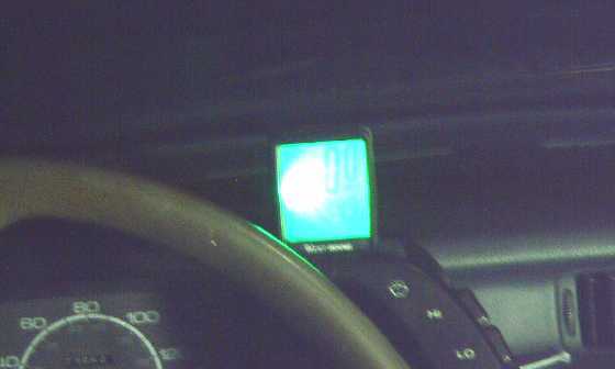 I had
assumed
that with a backlight in the speedometer, it
would be visible in the dark up on top of the dash with no light
on it.
Nope! The backlight only stayed on for a few seconds after a
button was
pressed, with no options to keep it on. I guess you're not
supposed to
go bike riding at night. I'd have preferred AAA battery(s) and
being
able to keep the light ON to a single use button cell and
"conserve all
possible power!" owing to that.
I had
assumed
that with a backlight in the speedometer, it
would be visible in the dark up on top of the dash with no light
on it.
Nope! The backlight only stayed on for a few seconds after a
button was
pressed, with no options to keep it on. I guess you're not
supposed to
go bike riding at night. I'd have preferred AAA battery(s) and
being
able to keep the light ON to a single use button cell and
"conserve all
possible power!" owing to that.
I wonder if I can find something a little more
appropriate
for the Miles mini cargo truck, which also needs one? (I ended up
ordering another one the same rather than spending time on line to
check out others. At least I know they work.)
 Back of speedometer from the
outside
Back of speedometer from the
outside
The next day I did go for a
drive across the acreage. It only hit about 19.4 KmPH bouncing
across
the rough lawn path. After this I stopped a while. I cleaned and
vacuumed the inside of the Nissan Leaf, then the Sprint. (Now it
can't
haul lumber!)
Later after I had adjusted the tire circumference
number I
went around again 3 separate times. I "booted it", and hit a "Max
Speed" reading of 25.6. The lane was too rough and too short to
pick up
more speed. (Hitting the corner to go up the hill at such speeds
got
exciting!) How much faster would it get up to on level pavement?
45
KmPH started to seem less likely. 35 or 40?
Since the car as configured with this motor surely
couldn't make it up my
steep driveway from the highway, I had come up with a "cunning
plan" to
drive out on the highway and go a short distance to my neighbor's
(they're usually away) and go up his shallower driveway, then
across
his long drive and then through his rough grass back to the far
side of
my own place, linking up with where I've been driving. But did I
really
want to do it? That section of highway wasn't level anyway, so not
the
ideal for a "level pavement" speed test. And it would surely leave
a
track on their lawn for quite a while. Maybe better to just say
"project complete" and put it away until I need it around the
acreage
again -- or can make that new motor at some hypothetical future
date.
De-clunking the Motor Mounting
[24th] A friend came
over
and I took him for the ride
across the acreage. When we got back he thought he'd investigate
the
"clunk" in reverse, so we opened the hood and he looked in while I
went
forward and back as bit. He showed me by pulling on it that the
motor
assembly was rotating more than I had realized, in both
directions. In
reverse, a protrusion in the plate was actually hitting the
plywood
battery shelf - the "clunk". I could also see what looked like an
easy
fix: as he moved it, a bolt on the plate upper edge moved almost
directly toward and away from the nearby rear mounting. I could
just
add one
more short steel joiner bar from there to the rear
support. That would make it form a triangle instead of just a
line,
virtually eliminating rotation of the assembly.
Later I went out and made it. Since it would be
pushing
when driving forward rather than pulling, I used a heavy, thick
"L"
bracket piece. After expanding its end hole, drilling a new one
for the
plate bolt and
cutting a bit off the bottom side at the end, it fit great. Trying
to
shove the motor
around showed it was much more solidly fixed into place than
before.
But it still had a "clunk". It seems to be coming
from
movement in the rear shock mounting itself. Apparently the rubber
reaches an end stop and the metal parts hit. The attachment angles
of
the steel straps bears further investigation.
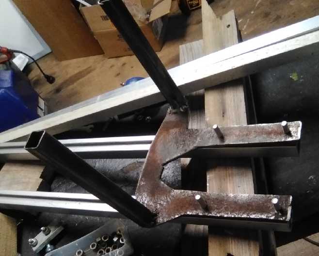
[August 4th] (As this
may
be the last write-up about the Sprint for some time, I'll put this
in with July.)
I looked at the original transmission bracket and saw
it
had held the rear cushion mounting at about 45°. Mine was pulling
it over to more like 70°, nearer vertical.
I put a block under the motor to hold it up, and
disassembled the rear mount pieces. I drilled a new hole in the
lower
piece that made it effectively a bit longer, and bent it to sit at
a
better angle on the mount.
On the upper piece I
drilled an end hole by the corner, higher up and more to the
outside to
improve
the angles and reduce twisting a bit. Then I tried to bend the end
across the face to get a more horizontal mounting angle, but the
metal
was too hard, too thick and too wide and it only bent a bit
striking it
with a 6 pound maul. Mostly it just jumped around or came loose in
a
vise. I almost gave up, then thought to cut the whole end narrower
with
the angle grinder, cutting in half the width to be bent. Then I
managed
to pound it around with the maul. A couple of other bends through
the
thickness helped line it up. If it wasn't sitting at the "ideal"
45° slope, it
was at least closer to 50° than 70°.
That seemed to eliminate the main "clunk". There was
still
a smaller, sharp "tink", always just once after changing from
forward
to reverse and pressing the pedal, that I'd probably missed
hearing
before. I figured this must be coming from
the drive shaft somewhere. I tried tightening set screws on the
shaft
coupler and found one (the one holding the speedometer magnet!)
wasn't
properly tight. And I tightened the wheel nut on the CV shaft a
bit
tighter. These things were to no avail. The sound was the same.
Perhaps
the remaining "tink" is in the actual CV joint, or in the
suspension?
(Hey, not my
fault?)
Other "Green" & Electric Equipment Projects
Off-Grid
infrastructure Components
T12V socket problem
I had managed to eliminate
putting anything covering the ends of the plugs and sockets of the
T-plug and mini-T-plugs, because they didn't mate well with even a
.8mm
end cover on each. But as I was using them, I started getting a
bit
nervous. With the mini plugs (12V) the blades in the sockets were
so
little recessed that, while they couldn't be plugged in backward,
inevitably people would inadvertently get them wrong occasionally,
and
the pins might actually make contact. Equipment was likely to get
fried.
Sure enough... I had made the Sprint car plug into
its 12V
battery so I could easily unplug it and the radio (and whatever?)
wouldn't gradually drain it if I
wasn't using it.
One day when I went to plug in the battery, as I was trying to
line up
the plug and socket, the plus pin from the battery socket touched
the
minus pin on the car plug (battery "-" and plug "-" both grounded
separately to car body)
and there was a spark. It wasn't backward, and I was still trying
to
line them up, not push them together, but they touched. (No
damage.)
(Technicly I should disconnect the separate ground wire from the
battery - it makes a "ground loop".)
I decided that after all there had better be some
thin
sheet of plastic covering the sockets, to recess the pins a bit.
So I
should redesign the socket shells and the wall plates. Even 1/2 a
millimeter should prevent accidental contact. Hopefully it
wouldn't
notably weaken the fit once plugged in. (But I didn't get around
to
doing any new socket shells yet.)
I don't think the T36 larger sockets suffer from this
problem, but I should probably try to deliberately connect them
wrong
in
various ways and find out.
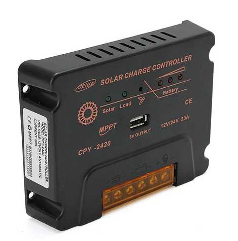
MPPT Solar Charge Controllers for Lead-Acid
 I
finally found a low cost charge controller that could
take the 35-40 volts from a full size solar panel and charge a 12
volt
lead-acid
battery from it. All the ones I had managed to uncover before that
said
"12-24V" would only work with a 12 volt battery if the solar panel
was
under 20 volts - in other words, only with small panels. The
description of the the "UEIUA CPY-2420" was pretty vague. It
sounded
like it might do the job, but didn't specificly say so. It
might be just like all the rest.
I
finally found a low cost charge controller that could
take the 35-40 volts from a full size solar panel and charge a 12
volt
lead-acid
battery from it. All the ones I had managed to uncover before that
said
"12-24V" would only work with a 12 volt battery if the solar panel
was
under 20 volts - in other words, only with small panels. The
description of the the "UEIUA CPY-2420" was pretty vague. It
sounded
like it might do the job, but didn't specificly say so. It
might be just like all the rest.
Two of them arrived weeks ago. (Ordered April 14th.)
At
last I got around to testing one, connected to a 305W panel and
two 6
volt golf cart batteries for 12 volts. It translated 36 volts from
the
panel to 12 volt charging voltages fine. I had feared it might
either
want a 24 volt battery or else put out high voltage spikes (ie, 36
volts) into the 12 volt battery, but the oscilloscope showed that
it
didn't and its lights showed the battery as "full", or as "low",
when
it was. And my power monitor showed that it seemed to find the
maximum
power point of the panel in the late afternoon clouds, current and
voltage changing some as I picked up the panel and pointed it in
different directions, or if I stood over it and darkened it.
I didn't want to sell them without checking one out
first.
Now that summer is getting old, I can advertise 305W panels with
charge
controllers for 12 volt systems that don't cost an arm and a leg,
for
off-grid/RV/boat uses. (I ordered 5 more for about 30$ each, my
cost.)
Handheld Bandsaw Mill Kit
[28th] I had been struggling in my mind (very occasionally) with
how to
make the undriven end with adjustments for the band tension and
alignment. The whole end had to be free to slide up and down the
main
backbone. It also was held to that backbone by bolt heads in the
track.
If the bolts were tight, obviously it couldn't move. If they were
loose
they always tipped - became crooked and jammed, so nothing moved
freely.
Now a plan finally occurred to me: make smaller holes
in
the plate and thread the bolts through it. Then put nuts on the
top
ends above the plate and tighten them against it, leaving slack
underneath so that the whole plate would slide easily.
[29th] Since the holes were already drilled too big to thread, I
put a
nut on each carriage bolt, then put it through the plate and did
up
another nut on top. It seemed to work well enough, and in fact is
probably better for aligning the carriage bolt squares. I had only
2
bolts go into the slots at the outer end so that it could twist
left
and right to adjust the wheel tracking.
I came up with the idea to use two short "L" brackets
for
each rail to adjust the tension. One would be attached to the
rail, and
the other to the plate. One would have a nut welded to it, and a
bolt
or threaded rod would be turned to pull the plate toward the right
end,
tensioning the band. Band tracking would be adjusted by loosening
one
and tightening the other, adjusting the alignment of the wheel. On
the
30th I scrounged pieces of 2 inch by 2 inch angle iron to use for
these.
I added washers to the bolts on the driven end to fix
it
in place. It could be permanently mounted right at the end of the
main
backbone with the outside of the wheel sticking out. That gives
the
most potential cutting width.
 Motor end plate
 Affixed with bearings and
wheel.
Affixed with bearings and
wheel.
I finally came up with the idea to make a "p" (or is
it
"d" ?) bracket. The "tail" part would have "ears" on it, visualize
them
going into and out of the paper. U-bolts would go through holes in
these ears to clamp it against the post. The bar would be free to
slide
through the square "o" part while being held not to move up or
down.
The "o" part should probably be a square tube a little bigger than
the
rail tube. I was thinking the tail could be cut and bent out of
the
ends of the tube, but it might be easier to weld on a flat piece.
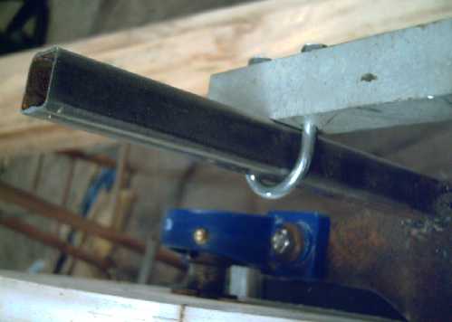 The left end of the
cutting-depth
guide rail is
the easy end:
The left end of the
cutting-depth
guide rail is
the easy end:
just clamp it to the post with a U-bolt.
(Cutting depth ruler markings on the posts would be a
substantial
asset!)
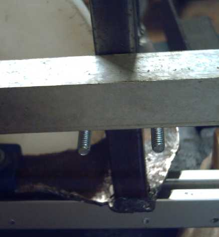 How to affix the right end
so the
whole plate can
slide left-
How to affix the right end
so the
whole plate can
slide left-
right, yet hold the cutting-depth guide rail from moving?
I thought there must be "square" U-bolts for my
square
posts and rails. On August 2nd I looked on AliExpress. Sure
enough! I
ordered a couple of pairs that looked about right; two sizes.
Gardening
My strawberries have nice green foliage, plenty of
flowers... and not a single berry for two years and very few the
two
years
before that - never a good crop. A neighbor being
something of an authority, I went and asked her about it, but her
[lack
of]
strawberries looked about the same as mine. (She only had a couple
of
plants.) There are various factors, but my best guess at this
point is
that I got
a variety that doesn't fruit well around here. I bought three new
plants - that had berries already on them - and I plan to dig up
the
whole bunch
of the old ones and let these ones' runners grow and take root.
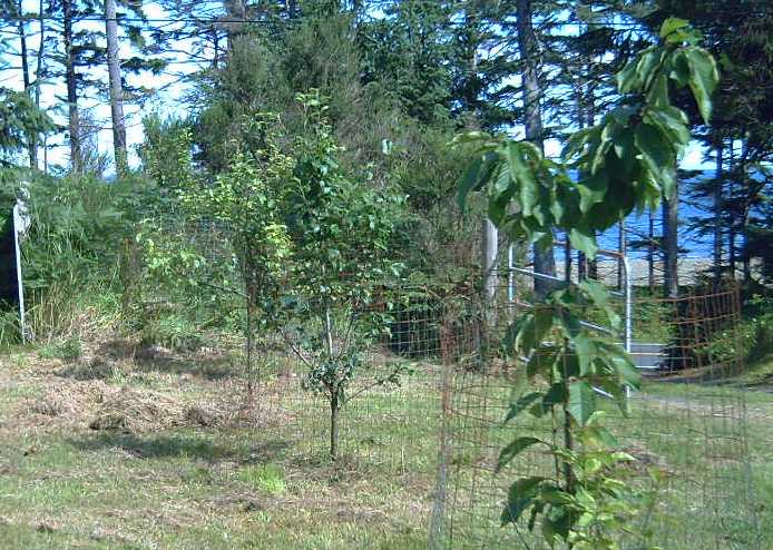 Hmm... one
tiny apple, two cherries, no pears or apricots between nine
trees. Healthy leaves and lovely flowers on most of them this year
and
hoverflies buzzing like a
swarm of
bees around the apricot, but nothing. So far in 4 years not a
single
pear or apricot, 11 apples all off the same tree (7 all off one
branch
in
2019!), and a handful of
cherries. My brother reports similar from his apple trees in
Toronto.
??? I dumped some
lime and sprinkled some wood ashes around the trees. (They each
got a
big pile of seaweed a couple of years ago.) Then I removed the
wire
fences from around them and cleared out all the grass, weeds and
ferns
that were threatening to envelop them. Maybe that'll help for next
year? (Late note: a gardener says to shelter them from the wind
off the
ocean. There's little doubt that would make a difference,
especially to
the end two.)
Hmm... one
tiny apple, two cherries, no pears or apricots between nine
trees. Healthy leaves and lovely flowers on most of them this year
and
hoverflies buzzing like a
swarm of
bees around the apricot, but nothing. So far in 4 years not a
single
pear or apricot, 11 apples all off the same tree (7 all off one
branch
in
2019!), and a handful of
cherries. My brother reports similar from his apple trees in
Toronto.
??? I dumped some
lime and sprinkled some wood ashes around the trees. (They each
got a
big pile of seaweed a couple of years ago.) Then I removed the
wire
fences from around them and cleared out all the grass, weeds and
ferns
that were threatening to envelop them. Maybe that'll help for next
year? (Late note: a gardener says to shelter them from the wind
off the
ocean. There's little doubt that would make a difference,
especially to
the end two.)
Of all my fruits only the blueberries are faring
really
well, and the raspberry canes I planted this spring were having a
small
crop by the end of the month. I picked a
pretty good bag of wild orange salmonberries from bushes growing
around
the back where I've made the new firewood shed, and there should
be some other wild berries later this summer. On the 27th I picked
thimbleberries beside the highway and made a "thimbleberry
cocaigne"
cake.
 For
vegetables I had several heads of broccoli early in the month
plus a bit of asparagus and cauliflower, and chard and beet
greens, and
a few peas - mostly from the greenhouse. One tomato so far, from a
bought
seedling that already had it growing.
For
vegetables I had several heads of broccoli early in the month
plus a bit of asparagus and cauliflower, and chard and beet
greens, and
a few peas - mostly from the greenhouse. One tomato so far, from a
bought
seedling that already had it growing.
Before the end of the month I bought hedge clippers
and
trimmed the asparagus so I could walk past it. It's also bending
over
against the greenhouse roof.
The corn is up to my chest and even my head, and
tassels
are forming at the tops. But where are the ears? There's no sign
of
any. (Please not another crop that grows great except for
the
crop!)
The peppers that overwintered from last year in pots
under
LED lights are making the tiniest peppers - hardly worth it.
Perhaps
they need fertilizing. Or maybe I don't water them enough? Carrots
are
doing poorly as usual. I think I don't water them enough when they
are
first coming up. Tending the gardens and especially watering
enough is
always a problem for me in gardening since I'm so busy with
everything.
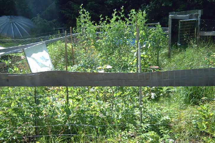 The
garden
looks wilder every week and really needs a weedeater taken to some
parts. But there are some good vegetables growing in it as well.
I've
picked a pound so far (29th)
from a lovely 8 foot tall row of tall
peas in the garden, which has entered its "mass production" in the
last
few days. It'll probably make a kilogram worth, and then some
other
peas planted later will make some more. (I recently finished
eating
the ones
from last summer that I froze.)
The
garden
looks wilder every week and really needs a weedeater taken to some
parts. But there are some good vegetables growing in it as well.
I've
picked a pound so far (29th)
from a lovely 8 foot tall row of tall
peas in the garden, which has entered its "mass production" in the
last
few days. It'll probably make a kilogram worth, and then some
other
peas planted later will make some more. (I recently finished
eating
the ones
from last summer that I froze.)
 When
I put down enough sawdust, the slugs seemed to leave my vegetables
more or less alone. But the quinoa seemed to attract many leaf
miners
and bugs that simply ate holes in the leaves. By the end of the
month
they looked pretty chewed up, even as the flowers started
attracting
hoverflies.
When
I put down enough sawdust, the slugs seemed to leave my vegetables
more or less alone. But the quinoa seemed to attract many leaf
miners
and bugs that simply ate holes in the leaves. By the end of the
month
they looked pretty chewed up, even as the flowers started
attracting
hoverflies.
After losing a lot of beans and things I finally made
enough sawdust to spread around the garden. This seemed to work
for
some weeks. But by the end of the month I guess it was rotting in
some
and it no longer repelled them, and they were eating my cabbages
and
beans again, even plants that I thought would by now be too big.
(If
they can't climb 'em they'll settle for chewing through the stem!)
In the little garden by the house leaf miners and
other
bugs (leafhoppers?) are making mincemeat of the quinoa leaves.
(Much
worse by the end of the month, but the flowers are growing
anyway.)
 This was
a
pile of dirt last year, but with a few potatoes in it. They
outgrew all
the weeds and made 10Kg of spuds. The deer seemed to leave them
alone.
So this year I flattened it down and made sure it was well
planted, and
I started two other patches in dirt piles.
This was
a
pile of dirt last year, but with a few potatoes in it. They
outgrew all
the weeds and made 10Kg of spuds. The deer seemed to leave them
alone.
So this year I flattened it down and made sure it was well
planted, and
I started two other patches in dirt piles.
The 4 hens are laying 2
or
3 eggs per day. So I sell some.
The lady says they're the best tasting eggs she ever remembers
having.
They get greens most days in addition to grit with clam shell bits
from
the beach, chicken feed, bird seed, sprouted wheat and kitchen
scraps.
(Welcome to the "Spoiled Chickens Ranch"!)
Electricity
Generation
My Solar Power System
Daily/Monthly/Yearly Log of Solar
Power Generated [and grid power consumed]
(All times are in PST: clock 48 minutes ahead of sun, not PDT
which
is an hour and 48 minutes ahead. DC power output readings - mostly
the kitchen hot
water heater for some months, since its removal mostly just lights
-
are reset to zero
daily (mostly for just lights, occasionally), while the others are
cumulative.) Note that the DC is actually power used since there's
nothing totaling up the amount incoming to the batteries, which is
(unless it's a lot and there's little sun) replaced the following
day.
Solar: House, Trailer, (DC@house) => total KWH [grid
power
meter
reading(s)@time] Sky conditions
Km = electric car drove distance, then car was charged.
June
30th 1832.30,756.38,(0) => 15.63 [55Km; 85575@21:30] Sunny
Again!
And warm until end of day; then from ~25° down to 14° before
dark!
July
01st 1841.84, 762.13,(.18) => 15.47 [85583@21:30] Sunny! 21°
02st 1851.97, 768.12,(.23) => 16.35 [90Km; 85601@21:00] Sunny
Again!
23° (must have been extra clear?)
03rd 1860.56, 773.37,(.23) => 14.07 [55Km; 85616@21:30] more
great
weather!
04th 1871.17, 779.74,(.10) => 17.08 [85622@21:30]
05th 1881.68, 786.17,(.00) => 16.94 [35Km; 85637@22:00]
06th 1892.22, 792.63,(.12) => 17.12 [55Km; 85648@23:00] yay
sunshine!
07th 1899.87, 797.25,(.00) => 13.37 [85653@21:00] Cloudy part
of the
day. Much cooler.
08th 1906.67, 801.30,(.22) => 11.07 [85662@21:00] Sunny PM.
09th 1913.49, 805.22,(.13) => 10.87 [90Km; 85687] Cloudy, faint
sunshine.
10th 1918.69, 808.32,(.00) => 8.30 [55Km; oops!]
The
"usual" cloudy, cool weather seems to have reasserted itself. (A
nice
summer was looking SO promising!)
11th 1925.12, 812.05,(.00) => 10.16 [45Km; 85705@21:30]
12th 1931.52, 816.03,(.00) => 10.38 [85715@21:30] morr cloudy.
But
hit
21°.
13th 1936.58, 819.03,(.00) => 8.06 [55Km;
85732@21:30]
Just a
bit of sun, briefly.
14th 1941.56, 822.12,(.64) => 8.71 [85744@21:30]
15th 1944.88, 824.08,(.13) => 5.41 [85752@21:00]
Days
are getting shorter bit by bit. And cloudier!
16th 1949.60, 826.86,(.00) => 7.50 [90Km;
85773@20:00]
Wow! Heavy if short downpour toward evening. We needed it!
17th 1957.16, 831.23,(.16) => 11.09 [55Km; 85795@20:30] Some
more
rain, clouds, and some sun
18th 1964,57, 835.48,(.05) => 11.71 [85805@22:00] Back to
cloudy,
occasional drops of rain, somewhat sunny patches.
19th 1973.46, 840.74,(.00) => 14.15 [60Km;85826@22:30] Sunshine
returns - Yay!
20th 1979.14, 844.07,(.00) => 9.01 [55Km; 85834@20:30]
Sun,
rain, sun, clouds
21th 1982.59, 846.00,(.00) => 5.38 [85847@23:00] AM
Cloudy,
PM a couple of downpours! (NOT the infamous "rivers from the sky",
just
a heavy rain. The rest of BC has hundreds of forest fires going
and no
rain. Firefighters are coming from Nova Scotia and Mexico!)
22th 1986.39, 848.15,(.21) => 6.16 [85855@19:30]
Clouds,
wind and rain. (Ug!)
23th 1992.08, 851.48,(.00) => 9.02
[85Km;85884@31:00]
clouds, drizzle, sun for a bit ~noon.
24th 1997.85, 854.96,(.62) => 9.87 [55Km;
85900@21:00]
Pouring rain early AM, a bit of sun, clouds.
25th 2005.30, 859.21,(.28) => 11.98 [90Km; 85923@21:00]
Downpour
overnight/early, some sun, hazy sun, more rain by evening. ~18°.
26th 2009.22, 861.59,(.00) => 6.29 [85933@20:30] Clouds
again.
27th 2015.88, 865.47,(.12) => 9.66 [50Km;
85948@20:30]
Clouds until evening then clear
28th 2021.47, 868.59,(.00) => 8.71 [85957@21:00]
clouds,
brief sun, brief rain.
29th 2024.44, 870.43,(.00) => 4.81 [55Km;
85974@21:00]
Fog, rain, bit of sun.
30th 2031.02, 874.21,(.19) => 10.55 [85Km; 85992@19:30] Clouds,
sun,
fog.
31st 2036.65, 877.59,(.45) => 9.46 [86001@19:30] More of
the
same.
August
1st 2044.12, 881.88,(.00) => 11.76 [86018@21:30] Some
decent
sun today - 21°!
2d 2049.77, 885.12,(.00) => 8.89
[86027@20:30]
3rd 2055.59, 888.71,(.00) => 9.41 [55Km;
86042@20:00] Sunny only occasionally but hit 21°!
4th 2059.00, 890.91,(.00) => 5.61 [86052@20:00]
Mostly
wind & rain. Later sun came out.
Daily KWH from solar panels. (Compare July
2021
with June 2021 & with July 2020.)
Days of
__ KWH
|
July 2021 (12 panels)
|
June 2021 (12 panels)
|
July 2020 (12 Panels)
|
0.xx
|
|
|
|
1.xx
|
|
|
|
2.xx
|
|
|
|
3.xx
|
|
1
|
1
|
4.xx
|
1
|
1
|
4
|
5.xx
|
2
|
2
|
4
|
6.xx
|
2
|
2
|
1
|
7.xx
|
1
|
2
|
3
|
8.xx
|
4
|
5
|
3
|
9.xx
|
5
|
3
|
1
|
10.xx
|
4
|
1
|
-
|
11.xx
|
4
|
3
|
2
|
12.xx
|
|
1
|
3
|
13.xx
|
1
|
1
|
3
|
14.xx
|
2
|
2
|
1
|
15.xx
|
1
|
3
|
4
|
16.xx
|
2
|
2
|
-
|
17.xx
|
2
|
1
|
-
|
18.xx
|
|
|
1
|
Total KWH
|
329.62
|
312.12
|
300.18
|
Km Driven
on Electricity
|
1105 (Leaf: ~150 KWH)
... + 2.5 Km (Sprint)
|
|
|
Monthly Summaries: Solar Generated KWH [& Power used
from
grid KWH]
2019
March 1-31: 116.19 + ------ + 105.93 = 222.12 KWH - solar [786 KWH
used from
grid]
April - 1-30: 136.87 + ------ + 121.97 = 258.84 KWH [608 KWH]
May - 1-31: 156.23 + ------ + 147.47 = 303.70 KWH [543 KWH]
(11th
solar panel connected on lawn on 26th)
June - 1-30: 146.63 + 15.65 + 115.26 = 277.54 KWH [374 KWH] (36V,
250W
Hot Water Heater installed on 7th)
July - 1-31: 134.06 + 19.06 + 120.86 = 273.98 KWH [342 KWH]
August 1-31:127.47 + 11.44+91.82+(8/10)*96.29 = 307.76 KWH [334
KWH]
(12th panel connected on lawn Aug. 1)
Sept.- 1-30: 110.72 + 15.30 + 84.91 = 210.93 KWH [408
KWH]
(solar includes 2/10 of 96.29)
Oct. - 1-31: 55.67 + 13.03 + 51.82 = 120.52 KWH, solar
[635 KWH used from grid]
Nov. - 1-30: 36.51 + 6.31 + 26.29 =
69.11
KWH, solar [653 KWH used from grid]
Dec. - 1-23: 18.98 + .84* + 11.70 =
31.52
KWH, solar + wind [711 KWH + 414 (while away) = 1125 from grid]
2020
Jan. - 6-31: 17.52 + ------* + 10.61 = 28.13
KWH,
solar+
wind [1111 KWH from grid]
Feb. - 1-29: 56.83 + ------* + 35.17 = 92.00
KWH,
solar + wind [963 KWH from grid]
* The solar DC system was running the kitchen hot
water
tank. Now it's only running a couple of
lights - not worth reporting. So there's just the 2 grid tie
systems:
house and "roof over travel trailer".
One year of solar!
March - 1-31: 111.31 + 87.05 = 198.37 KWH solar
total
[934 KWH from grid]
April - 1-30: 156.09 + 115.12 = 271.21 [784 KWH
from grid]
May - 1-31: 181.97 + 131.21 = 313.18 KWH
Solar [723 KWH from grid]
June - 1-30: 164.04 + 119.81 = 283.82 KWH Solar [455
KWH
from grid]
July - 1-31: 190.13 + 110.05 = 300.18 KWH Solar
[340
KWH from grid]
August- 1-31: 121.81 + 83.62 = 205.43 KWH Solar
[385KWH
from Grid]
Sept. - 1-30: 110.68 + 65.09 = 175.77 KWH Solar
[564
KWH used from grid]
Oct. - 1-31: 67.28 + 42.55 =
109.83
KWH Solar [1360 KWH from grid -- Renters!]
Nov. - 1-30: 35.70 + 20.79 =
56.49
KWH of Solar [1301 KWH from grid]
Dec. - 1-31: 19.78 + 11.31 =
31.09
KWH Solar [1078 KWH used from grid]
2021
Jan. - 1-31: 25.47 + 18.58 =
44.05
KWH Solar [1185 KWH used from grid]
Feb. - 1-28: 47.18 + 33.22 =
80.40
KWH Solar [1121 KWH used from grid]
Two years of solar!
March - 1-31: 81.73 + 55.22 + 2.2 (DC) = 139.15
KWH
Solar
[1039 KWH grid]
April - 1-30: 161.83 + 112.35 + .44(DC) = 274.62
KWH
Solar
[680 KWH from grid]
May - 1-31: 156.25 + 97.22 + 1.29(DC) =
254.76
KWH
Solar [678 KWH from grid]
June - 1-30: 197.84 + 112.07 + 2.21(DC) = 312.12 KWH
Solar
[& 448 KWH from grid]
July - 1-30: 204.35 + 121.21 + 4.06(DC) = 329.62
KWH
Solar [426 KWH from grid]
Things Noted - July 2021
* The sunny week at the start of July made it the best month of
all
I've recorded so far for solar power, if only by a small margin.
* If we were to actually got a whole sunny month here instead a
few
sunny days here and there, solar power might average say 16 KWH
per day
of collection in June or July: 16KWH * 30 days = 480+ KWH for a
month.
The best we ever seem to do here is about 2/3 of that. I would
rather
live here than in a desert, but a desert, and a more southerly
latitude, has the best return on investment for solar power -
witness
where the huge Chinese solar installations are (Month in Brief).
Annual
March 2019-Feb. 2020: 2196.15 KWH Solar [used 7927 KWH
from
grid]
March 2020-Feb. 2021: 2069.82 KWH Solar [used 11294 KWH from grid]
(See TE News #156 for the two year writeup... which technicly
should
have been two months earlier.)
Electricity
Storage
(Batteries)
Turquoise Battery Project
Goal: Long lasting, low cost, high energy
batteries
[10th] On a whim I decided to try just salt electrolyte again. How
without making a new cell? I
removed the top cover of the "C" cell I made a couple of months
ago,
and immersed the whole cell in water a couple of times to dissolve
and
dilute out the
present electrolyte, the mix of potassium hydroxide and potassium
chloride.
I discovered that the top of the cupro-nickel tab had
oxidized off. Rats! Here I thought I finally had found a metal
that
wouldn't oxidize. It looked like graphite was once again the only
thing
that would work. And in changing the electrolyte to chloride
without
the hydroxide, it would probably be the only thing anyway. But
inside
the electrode, the rest of the metal seemed fine. It was just
where it
came out the top that it had turned green and corroded away. Maybe
if
it was well sealed where it came out, it wouldn't happen?
[21st] Well, finally I got to it! I cut off the top of the
cupro-nickel
electrode
under the lid. It seemed quite solid inside the cell. For now I'll
go
with (more certain) graphite - a 1/4 inch carbon rod. (That's the
smallest I have.) I trimmed it to a chisel shape, drilled a 1/4"
hole
in the lid, and inserted it into the electrode. For all the
compaction
I had done when I made it, the rod inserted maybe 3/4 inch, at
first
pretty easily. Then I dripped in some 35% potassium chloride.
The cell sat at about 290 mV. [10:20 AM PDT] I
connected
about 1.95 volts from the power supply and it shot up. It started
charging at about 70 mA. That soon dropped to 50, but it stayed
there.
Not high current, but it beats 5 or 10 or 20 mA. When I took it
off
charge, the voltage dropped rapidly, but was climbing a bit each
time.
At one point it put out 150 mA if shorted. And then it would start
charging at 70 mA again, again dropping to 50 after a bit. By 15
minutes it was at 45 mA, and over 1.5 V when the charge was
removed but
of course it dropped rapidly.
[11:40 AM PDT] Charging at 40 mA. Held over 1.6 V momentarily when
taken
off charge but dropped with seconds. Put out 220 mA short circuit
current, but only recovered to 1.3x V and started dropping again.
Okay, still seems leaky as heck whatever the
electrolyte.
Is there any hope? Whatever I do, I can't seem to make a cell that
just
sits there and holds its charge.
I decided that instead of charging it, I would short
it
out and discharge it completely. Would anything change? [13:20 PM
PDT -
actually still AM] I figured that was long enough an un-shorted
it.
Then I connected the charge at barely under 2.0 volts. It started
at
220 mA, but was soon down to 70. [13:50] Down to 30 mA. At one
point it
put out 240 mA shorted for a moment.
Eventually it was down to 10 or 15 mA. By bedtime it
was
holding higher voltages for much longer - 1.8+ for a few seconds.
But
over some days, as seems so typical of my cells, the performance
became
pathetic and it didn't hold voltage very long.
---
Next Cell
[27th, 28th] Commercial manganese dioxide - zinc cells in
hydroxide
electrolyte have "zinc paste" connected to a short piece of wire
as the
negative electrode. I wonder what would happen if, instead of
trying to
plate metallic zinc, a thin layer of that zinc paste was applied
to the
copper can? Everything else could be the same. Better still, how
about
pasting it into the outer layer of graphite felt, mixed with a bit
of
zirconium silicate to raise the hydrogen overvoltage?
Then the layer of agar and the separator sheet, and
then a
rolled up electrode from a Ni-MH dry cell, in order to reduce the
number of unknowns? Those had worked for me before. But in salt
electrolyte the nickel mesh current collector will oxidize. I can
sprinkle in some conductive graphite powder, with samarium oxide
to
raise the oxygen overvoltage, between the layers. It won't be very
well
mixed. (I suppose I could crumble up the electrode(s) and just use
the
powder without the metal sheets?)
Formed Copper Can
Not to make a whole extra job, but if I made
something to
clamp the end of a short piece of 3/4 inch copper pipe, perhaps I
could
make some rotating tool to expand the pipe in a drill press or a
lathe.
Hmm... a disk piece that fit inside, and put the pipe in the lathe
chuck to turn with the tool stationary, would be easiest since I
have
the lathe.
I keep wanting to try out this sort of thing. I cut a
piece a bit longer than the C-cell, then heated it red hot to
anneal
it. (Tempered copper won't stretch or bend well. It would be
likely to
break.)
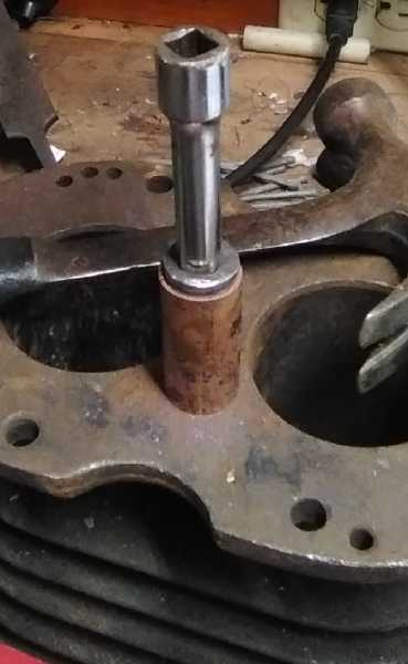 Then
I thought
of simply pounding or pressing wedges into
the pipe. That sounded too simple, but it was probably worth a
try. It
probably should be expanded a bit at a time, or else the end would
probably squash instead of the pipe expanding. What to use?
The
only thing I could think of having various close sizes was drill
bits.
Then I saw my socket wrench set. Aha! I had some odd ones in a
tin,
too. I found an old socket that was just slightly larger than the
pipe
and ground the end to a taper so it would go in, then I polished
it. I
put in an old extension rod and pounded it most of the way through
the
pipe. I could see the slight bulging as it went. Since I didn't
want to
expand the bottom and in fact wanted to make it a closed end, I
stopped
and pounded it back out the way it went in.
Then
I thought
of simply pounding or pressing wedges into
the pipe. That sounded too simple, but it was probably worth a
try. It
probably should be expanded a bit at a time, or else the end would
probably squash instead of the pipe expanding. What to use?
The
only thing I could think of having various close sizes was drill
bits.
Then I saw my socket wrench set. Aha! I had some odd ones in a
tin,
too. I found an old socket that was just slightly larger than the
pipe
and ground the end to a taper so it would go in, then I polished
it. I
put in an old extension rod and pounded it most of the way through
the
pipe. I could see the slight bulging as it went. Since I didn't
want to
expand the bottom and in fact wanted to make it a closed end, I
stopped
and pounded it back out the way it went in.
Then I got a slightly
larger socket from my set and filed a taper onto it, and polished
it
too. I dont think the bit I took off the back end should hurt it
when
using it for its original purpose. I pounded that in like the
first and
expanded it a bit more. I could push the sockets in by hand after
pounding them in, and now the first socket just fell in. The pipe
had
expanded from 19.67mm to 20.90mm. The wall thickness had gone from
1.3mm thick to about 1.1mm, with a fat spot up to 1.17mm at the
seam.
The outside went from 22.3mm to 23.15mm and about 23.2 at the
seam. The
bottom was a bit lop-sided. It needed to be inside complementary
wedge
shapes to start squeezing it closed as the rest was expanded.
I measure a C-cell as about 25.4mm O.D. Allowing say
1mm
for a cardboard outer sleeve, that means just a couple more
expansions
of a millimeter or less. If I can make some wedges to have the
bottom
squeeze closed in the same process, this should be quite workable
for
prototypes, and hopefully I won't have to do any silver soldering
and
ending up with leaks.
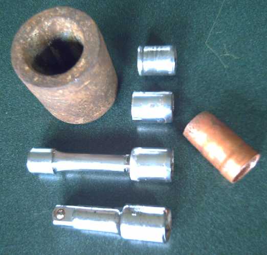 I found a
heavy round piece with
a tapered hollow inside.
Some sort of plug for a boat? It was here when I bought the house.
It
looked about right for starting to taper down the bottom of the
pipe. I
put the pipe into it and a larger tap, which I thought was a bit
too
big to go into the pipe if I pounded on it. But it did, expanding
the
top of the pipe considerably more than I had intended for one
pressing.
With nothing to hold the pipe straight in the tapered sleeve, and
with
no proper taper entering onto the die, both the bottom and the top
started getting lop-sided. I only went down 1/2 inch, which seemed
to
be expanded to pretty much the exact desired outer diameter - and
a bit
more in one direction because of going in crooked.
I found a
heavy round piece with
a tapered hollow inside.
Some sort of plug for a boat? It was here when I bought the house.
It
looked about right for starting to taper down the bottom of the
pipe. I
put the pipe into it and a larger tap, which I thought was a bit
too
big to go into the pipe if I pounded on it. But it did, expanding
the
top of the pipe considerably more than I had intended for one
pressing.
With nothing to hold the pipe straight in the tapered sleeve, and
with
no proper taper entering onto the die, both the bottom and the top
started getting lop-sided. I only went down 1/2 inch, which seemed
to
be expanded to pretty much the exact desired outer diameter - and
a bit
more in one direction because of going in crooked.
I filed a taper in a socket of the size in between
the
previous one and this "rogue" largest tap, and expanded it to that
size
full length minus the bottom taper. Then I filed a taper on the
largest
one, which was a 1/2 inch drive socket extension rather than an
actual
socket. I also put a metal ring into the sleeve to hold the piece
more
centered. This time it went in pretty straight. It didn't pound
quite
as far into the tapered sleeve as needed. I could start with a
longer
piece of pipe next time. The diameter was perfect, about 24.8mm.
Wall
thickness was about 1.14mm all around. I was no longer sure where
the
seam had been.
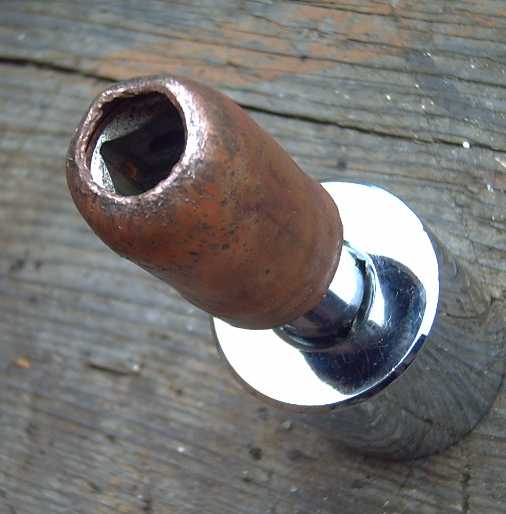 Now it was time to start thinking of how to close off the
bottom end. Lacking any better idea, I started tapping the end
over
with a hammer, with the punch still inside. I annealed the end
again
and continued pounding, but I couldn't get the center hole closed
off.
Now it was time to start thinking of how to close off the
bottom end. Lacking any better idea, I started tapping the end
over
with a hammer, with the punch still inside. I annealed the end
again
and continued pounding, but I couldn't get the center hole closed
off.
It was already too short to be a C-cell. Apparently
the
tube shrank in length as it increased in diameter.
I gave it another try with a new tube and trying to
leave
more metal at the end. It came a little closer to shut, but not
much.
At this point I gave up on closing the end. Then I accidently bent
and
ripped the tube trying to get the ends perfectly square on the
lathe. A
hollow copper tube is too soft to put in a lathe chuck!
So I
made a
third tube. Using a pipe cutter
(instead of the
angle grinder with a zip disk) the ends start out square. And this
time
I used the pipe cutter and a file to square them again after it
was
expanded. Also I had got tired of pounding the punches through the
tube
and this time I used the hydraulic press - a smoother process.
So I was back to punching out a 1 inch flat disk for
the
bottom and silver soldering it on. (Rats!) At least the new pipe
was
the right diameter for that to fit on the bottom instead of
inside. The
soldering went well. I dissolved off the flux (and pretty much
everything else!) in hydrochloric acid.
This time I put water in it, covered it with my
lips and blew on the top. (Last time I just filled it and none
came
out, but when I went to use it it did leak.) I figured if there
were
any leaks this time the
water would come squirting out. None did.
Finally, I started
asking
myself why I was beating my head against a wall when I had
already, and
quite a while ago, solved the main hurdle: the ancient mystery of
how
to get an everlasting zinc electrode - surely worth a fortune in
itself. (see July in Brief)
https://www.TurquoiseEnergy.com
https://TurquoiseEnergy.neocities.com
Haida Gwaii, BC Canada