Turquoise Energy News #159
covering
August
2021 (Posted September 9th 2021)
Lawnhill BC Canada - by Craig Carmichael
www.TurquoiseEnergy.com
= www.ElectricCaik.com
= www.ElectricHubcap.com
Month
In
"Brief"
(Project Summaries etc.)
- Ground Effect Vehicle - Peltier Cooler Experiments - Handheld
Bandsaw Mill Kit - Unipolar "Electric Hubcap" Motor New Thought: a
Higher-RPM-Safe Flat Magnet Rotor for Axial Flux? - Cabin Wall
In
Passing
(Miscellaneous topics, editorial comments & opinionated rants)
- Institutions of Governance - Smol Thots - ESD
- Detailed
Project Reports
-
Electric
Transport - Electric Hubcap Motor Systems
* Preliminary testing of the Ground Effect Vehicle RC model
Other "Green"
& Electric Equipment Projects
* Peltier Cooler Experiments: Lower Voltages for Greater Efficiency Etc.
* Handheld Bandsaw Mill Kit progress
* Greenhouse, Gardening
* Attracting a Swarm of Honeybees?
Electricity Generation
* My Solar Power System: - Daily/Monthly
Solar Production log et cetera - Monthly Summaries and
Estimates
Electricity Storage
* Turquoise Battery Project
(NiMnOx-Zn in Mixed Alkali-Salt electrolyte)
- There may be No further reports on this subject: Hey, I tamed zinc,
and I even tamed manganese as a negative electrode! Anybody who does
batteries should be able to take it from there!
My plan was to focus on the handheld bandsaw mill kit this
month and it is coming along, but with other priorities I didn't get it
finished to where I could run it.
Aside from trying to get better at
growing food, working on the greenhouse and running
or improving the acreage, I seem to have somehow also touched on the
ground effect vehicle RC model -- and on solid state peltier module
refrigeration again.
The month's gardening is under Other Green Projects
in the detailed reports. (Some may be interested that I found an easier
way to shell peas -- at least, it's faster than the way I've done it
all my life.)
And I have a refinement to the idea of a flat plate magnet
rotor with holes for "plugs" of epoxy to help hold the magnets more
securely.
After putting the south door on, I also finally got just a
bit more done on my cabin walls after neglecting it all summer.
[September 8th] This newsletter seems to be taking forever
to finish up! It's eating into September's project times - 1/4 of the
month is gone!
Ground Effect Vehicle
I couldn't seem to get at the programming for the
left-right motor steering controls, and I decided to at least run the
model without steering and see what happened. I made a "splitter" plug
and cord that let me plug both motors into the one "throttle" output
from the receiver. After a few glitches I got both motors to run
simultaneously when I pulled back the throttle stick. Although I hadn't
put on the bottom skin of the wing or the vertical steering fin, I took
it outside. (I haven't glued the fin on yet because it sticks out
adding a third dimension that will make the model hard to carry around
the house and to store. Maybe I should make it bolt on? ...at this
point, how?)
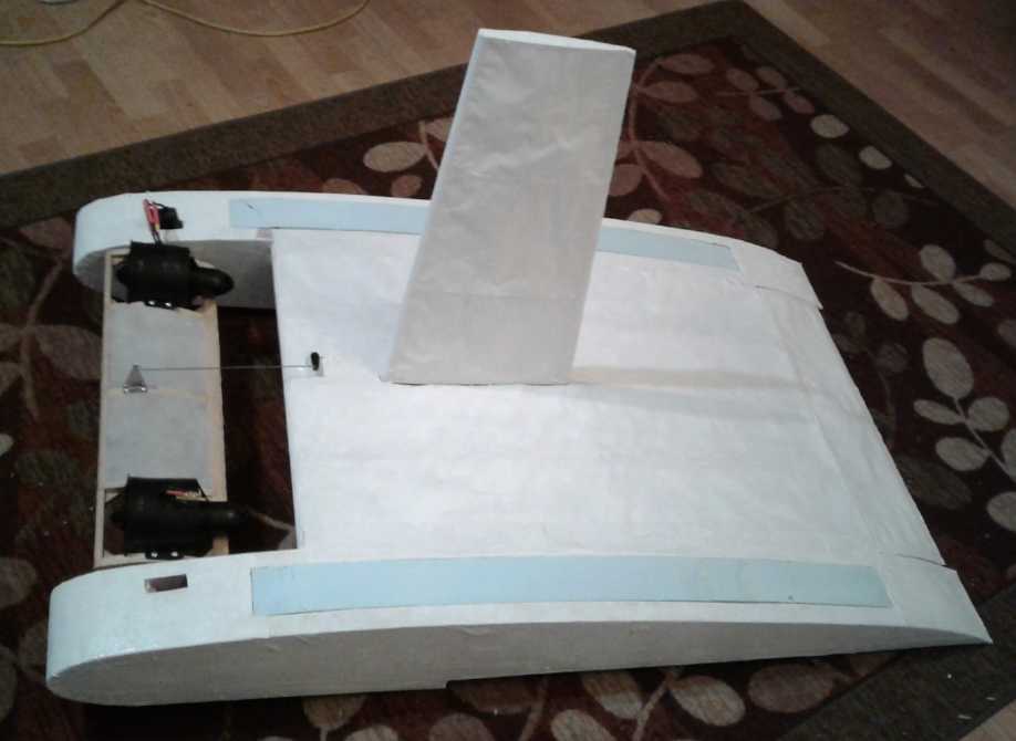 Sorry, no new pictures. It still
looks much the
same as in (ouch!) December 2019.
Sorry, no new pictures. It still
looks much the
same as in (ouch!) December 2019.
I aimed the canard up with the radio control, to aim the
ducted fans to blow their air under the
wing. On the first try on my freshly cut lawn, it seemed to be off in a
few feet and then it spun around. One fan had sucked in a big clump of
the cut grass and was clogged. I pulled the grass out through the
blades one lump at a time with needlenose pliers.
I took it over to the edge of my property by my neighbor's
and flew it onto his lawn, which hadn't been cut so recently. I got
in a few short flights and got some impressions of the operation. They
were short because with no steering, it would soon veer off to the left
or right, and with no fin, if not stopped it would at some point spin
around even facing back the way it came.
The ducted fans were amazingly powerful, as they had
advertised. In fact I didn't like to be very close to them without
hearing protection on. So there was no question but that the craft
would move. That it went off so fast said it was flying - or at least
skimming along the grass - almost
immediately. So the first conclusion was that the ducted fans blowing
air under the wing made for fast, low speed take-offs as intended,
expected and hoped.
The back end was well up, but the front was still pretty
much within the grass, leaving a trail in it and probably skimming
the ground. And that was with the canard pointed all the way up.
Pointed level, the
nose was on the ground and from a stop it wouldn't start moving.
So the second conclusion was that it was badly balanced.
The center of gravity was way in front of the center of lift. And this
really only made sense: the wing profile was designed to make a ground
effect craft more longitudinally stable. The center of lift was
substantially farther back than for a typical airplane wing, and the
wing went right to the back. (The canard is "typical airplane wing"
profile.) The weight was all near the front. Lifting it disclosed that
the
center of gravity was only about 1/5 of the way back on the wing. It's
probably wasting much of the ground effect lift with such a shallow
angle of attack by the wing.
It would seem I should position the batteries (half the
entire 5 Kg weight of the model!) farther back to get better balance,
which would make for a better overall "pitch" while flying. Then the
flight position of the canard should be more level.
(Move the center of gravity farther back: I knew I would be very glad I
had made a radio controlled model before
ever attempting a man size version, however absurdly long it's taking!)
I moved the batteries a little way back - the wires
weren't long enough to do more without rewiring. The rear was a little
lower, but it skidded along the ground even with the canard pointed
full
up and fans blowing full down under the wing. Next (whenever that may
be) I'll lengthen the wires and move them farther back. ...and hope it
can actually fly if the weight distribution is good!
Peltier Cooler Experiments
 Having got
some supposedly better peltier modules almost a
year ago, I finally got one out and tried to fix my solid state camping
cooler. (The peltier in it previously had quit. Perhaps I burned it out
with a 17 volt solar panel when camping in 2015? - it hadn't worked
except maybe near the beginning of that trip as I recall.) It didn't do
as well as the original module (TE News #54, which was larger physicly
[40x40mm versus 30x30mm] and higher current electricly ["6 amps" versus
"5 amps").
Having got
some supposedly better peltier modules almost a
year ago, I finally got one out and tried to fix my solid state camping
cooler. (The peltier in it previously had quit. Perhaps I burned it out
with a 17 volt solar panel when camping in 2015? - it hadn't worked
except maybe near the beginning of that trip as I recall.) It didn't do
as well as the original module (TE News #54, which was larger physicly
[40x40mm versus 30x30mm] and higher current electricly ["6 amps" versus
"5 amps").
But now having an adjustable DC to DC converter I got to
try
it out it at several voltages from 7 to 12, instead of being stuck at
12 (or whatever some power source gave me). Since the modules are more
efficient at lower voltages I found best cooling - at least as I had it
set up - was at about 8 or 9 volts at just 21 or 27 watts, and
increasing the voltage only used more power without making the interior
noticeably colder.
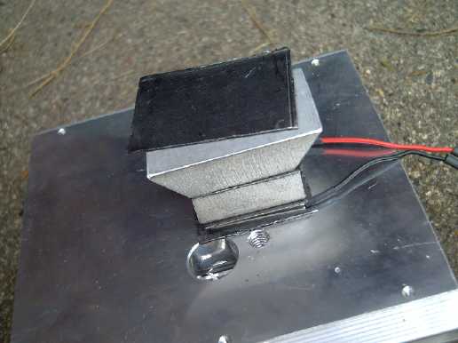
The warm side heatsink was getting up to
32-35°C in a 22° room in spite of the fan blowing air across
it, even with a plastic shroud directing the fan's air right across it.
The
cold side heatsink generally measured about 4° below the cooler's
overall temperature.
So it was cooling the cooler by just 12° to 10°,
but across a (32° - 6°) = 26° actual temperature drop
across the two heatsinks - and so even slightly more between the two
sides of the peltier module. Well, that big temperature differential
did much to explain poor performance.
How could the heat generated by the warm side, and the cold from the
cold side, be dissipated with lower temperature differences? That was
the key to better cooling with lower
input watts. (I think I was doing better than this with my "super
insulated" solid state chest fridge in 2012-2016. Its big ice tray
would at least partly freeze. But maybe it was by virtue of cooler room
temperature in my almost year round chilly kitchen in my old house in
Victoria BC! My house was most comfortable when other people around
town were
complaining about the heat!)
 I chafe that
no one wants to make and sell heatsinks of pure aluminum, since it has
better heat transfer than any alloy. I think manufacturers don't like
it because it's so soft and so the fins are easily bent. Fine for
transistors, but it would be very beneficial for peltier modules where
it's hard to get the heat away and every degree counts.
I chafe that
no one wants to make and sell heatsinks of pure aluminum, since it has
better heat transfer than any alloy. I think manufacturers don't like
it because it's so soft and so the fins are easily bent. Fine for
transistors, but it would be very beneficial for peltier modules where
it's hard to get the heat away and every degree counts.
Pure copper and silver transfer heat better than aluminum
(and still better than aluminum alloy), and I used a copper bar to good
effect transferring the cold into the fridge. Now I've come up with the
idea of a copper or silver plate with tapered edges to spread the heat
from the surface of the peltier module to a larger area before it
contacts the aluminum heatsink.
I also remembered to use thin graphite gasket instead of
"heatsink grease". The gasket has enough flex or "sponge" to contact
the whole of the two surfaces together, and transfers heat much better
than the paste.
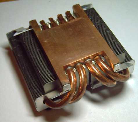
Sitting inside the cooler when I got it out was
a seemingly well designed
CPU heatsink someone had given my some years ago. It seemed to have a
copper block as the bottom of the heatsink.
I thought I would try it and see how
much the warm side temperature could be reduced toward room
temperature. But it didn't really seem to work as well as either the
biggest heatsink (which I also tried) or the one that came with the
cooler.
In the end I put it back as close to factory condition as
I could manage (having lost the original aluminum heat transfer block
somewhere). I don't think it works quite as well, cooling by just 11 or
12° below room temperature. According to Canadian Tire who still
sell it, 16 or 18° should be possible, but I don't think mine ever
cooled that much - maybe by 14°. And this peltier module is
physicly smaller and has a lower current rating (~4.5 amps at 12 volts)
than the original (6 amps). It does get the cooler just as
cold running at 8 or 9 volts as it does at 12 volts, using far less
power - as little as 20 watts instead of over 50. Peltier module
performance graphs indicated this might be the case, and seeing how
that would actually work was the biggest original point to the
experiments.
Having spent far too much time on such a trivial project
for which I had no immediate use (much more detail in "Other
projects"), I put the cooler away again.
Handheld Bandsaw Mill Kit
I continued working on this. I made a few changes and
revisions, and it's looking promising. After several tries I finally
silver soldered a blade band together that didn't quickly break. Even
if it doesn't stand up to cutting, it has to be there to set things up
and the ones that broke didn't help.
But in the last week of the month (not to mention the first one in
September) there were other priorities and I had to set it aside. It
won't take a lot more before it's running again, and then I can start
on the CNC cutting CAD/CAM files. And milling some 2" by 4"s from 6" by
6"s that I need for the cabin wall. More depth in the detailed report
in "Other Projects".
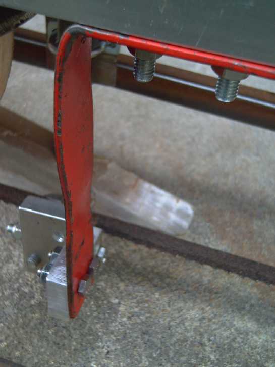
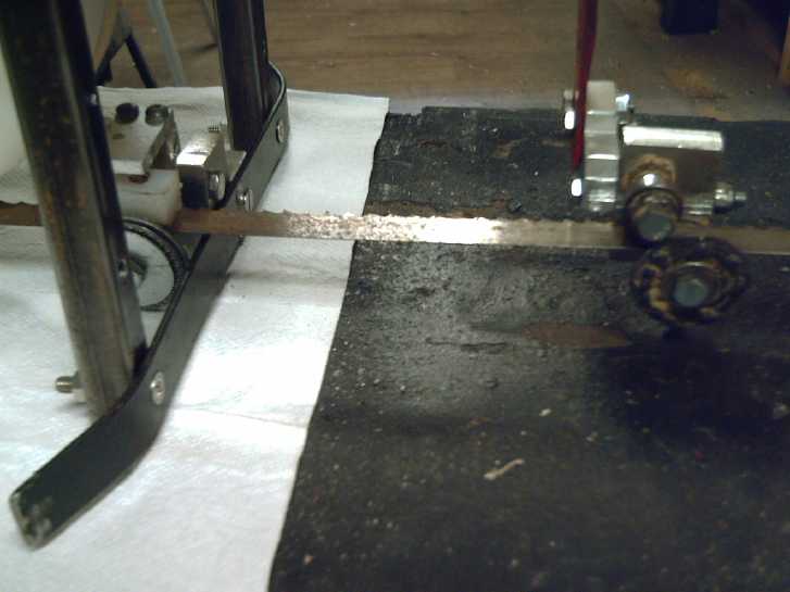
 Early in the month, the cutting
depth bars
Early in the month, the cutting
depth bars
(If there was a band, it would be cutting the bench.)
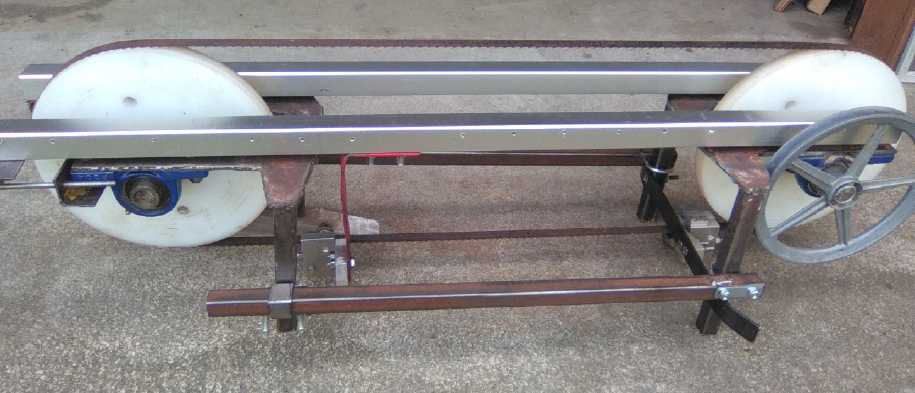
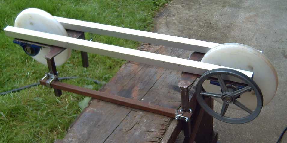
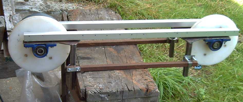
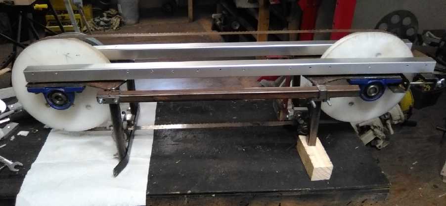 Later, the band guide wheels
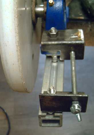 Right wheel: tensioning and
tracking adjustment
screw
Right wheel: tensioning and
tracking adjustment
screw
(one on each side of the wheel)
Various lengths of cutting bands can be accommodated
by sliding these assemblies along the rail.
 Band guide wheels. The right
wheel can be moved
anywhere
Band guide wheels. The right
wheel can be moved
anywhere
along the track to optimally cut different widths of lumber.
(I'm still using the old design guide wheels and assemblies
for present convenience - one more thing to update later!)
Unipolar "Electric Hubcap" Motor New
Thought: a Higher-RPM-Safe Flat
Magnet Rotor for Axial Flux?
The idea of making the new model of Electric Hubcap motor
as an outrunner (rotor outside from the stator with the magnets facing
in) instead of axial flux (magnets on rotor side by side with stator)
has only one special appeal: being on the inside of a steel rim, it
would be harder for centrifugal forces to break the magnets off the
rotor. That's the weak point of flat plate rotors and axial flux.
Other than that, the outrunner drum rotor is heavier and
making all the
magnetic surfaces with the ideal curves would be a parts nightmare (at
least for
prototyping and limited production), plus the molds for the PP-epoxy
body parts get more complicated. I figured I could get away with flat
components anyway, but there would be some things I
haven't tried before and adjusting the flux gap (and finding the
optimum gap) would be difficult to impossible.
So... if I could come up with a more secure and less labor
intensive means of mounting the magnets on a flat plate rotor to make
them safe at higher RPMs, in every other way I'd surely be farther
ahead. I would build it just the same way as my previous motors.
But I have had my fill of magnets breaking off rotors and
stators. So far: a lawnmower motor (stator), where it appears the glue
failed, early electric hubcap motors that I put rust primer on the
rotor before the magnets: the rust paint broke away from the rotor
steel, an
electric hubcap motor that I over-revved, and my lawn tractor (stator)
where the glue failed on one magnet and two other cheap sintered
(ceramic?) magnets actually fractured internally just inside the glue -
the glue itself didn't fail. The magnet on the over-revved motor
actually went through the thin outer shell (teaching me to make them
thick for safety!) and a 3/4 inch particle board tabletop.
So... How can safety be assured? Putting a PP-epoxy strap
all the way around each magnet is extra work and adds to the physical
height of the magnet and the thickness of the rotor plate. And if the
glue comes loose, it will vibrate and need repair anyway even if it
doesn't fly apart. Something
that occurred to me a while back would be to make holes in the rotor
plate behind the magnets, and fill them with epoxy "plugs". Thus the
epoxy
behind the magnet doesn't end at the plate surface. Still the magnet
itself could delaminate - it's corrosion protective skin could break
away from the inner magnet.
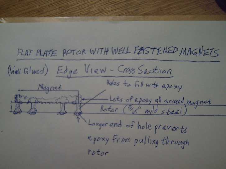 Now it occurs to me to put such "plug" holes in the plate around
the edges of the magnet, and to paint epoxy around the magnet's edges
as well as onto the rear to fill the holes. This extra support around
the edges would to
an extent mean the magnet was effectively attached on 3 or even 5 sides
out of 6 instead of just on the back. The more epoxy there was around
the edges, extending back through the plate holes for a good grip, and
of course the more holes there were (within reason), the more secure it
would be. (One might even stuff some PP cloth into the holes? Thicker
epoxy would be better held in place while it set. Or two+ coats of
epoxy could accomplish the same thing?)
Now it occurs to me to put such "plug" holes in the plate around
the edges of the magnet, and to paint epoxy around the magnet's edges
as well as onto the rear to fill the holes. This extra support around
the edges would to
an extent mean the magnet was effectively attached on 3 or even 5 sides
out of 6 instead of just on the back. The more epoxy there was around
the edges, extending back through the plate holes for a good grip, and
of course the more holes there were (within reason), the more secure it
would be. (One might even stuff some PP cloth into the holes? Thicker
epoxy would be better held in place while it set. Or two+ coats of
epoxy could accomplish the same thing?)
Might I hope 3500 RPM would prove safe? That would (eg)
put the Sprint on the road, and adding the zero losses variable torque
converter would optimally couple the motor to the load for the best
performance from the smallest motor.
I'm hoping these new motors
wouldn't overheat running at 150
amps (5400 watts, over 7 HP). That is perhaps a bit of a tall order.
(and still not a
"muscle car" by any means!) I would note that
with all the plastic parts, the motors are not only very light by
traditional motor standards, but they also have very low thermal mass.
And the plastic can't take really high temperatures.
With the Kelly controller delivering over 100 amps (so 3600 watts) with
heavy loads in Chevy Sprint trials around 2016, the electric hubcap
motor coils had heated up quite quickly. And with the Electric Caik
outboard having shown that at least that small version doesn't cool
very well, I may incorporate ducts to connect a blower fan for
additional
forced air cooling independent of the spinning of the motor itself.
That's still a minimal addition in lieu of the radiator and liquid
cooling found in most commercial cars, even electric ones.
By making the new motor so similar to my previous ones,
and using a trailer stub axle and hub as a solid, robust rotary center
for
everything, I should think that once the CNC router table is running to
make molds for the body shell parts, the new model could actually come
together very quickly.
Then, at what point might the whole thing (95% efficient
motor, controller, 100% efficient variable torque converter) become a
simple kit to
convert fuel burning cars? That's farther off in dreamland.
Cabin Wall
I finally got back to the cabin, after neglecting it since
early May - all summer! At some point I put the door on. Then I could
finally move on with the alium* siding. Near the end of the month I
finally got started framing the west half of the wall. Maybe I can
finish the south wall (exterior) before winter sets in? One excuse for
procrastination on the framing: I wasn't sure where I would put the
windows. I'll want probably one more small one somewhere toward the far
left. (Now... where... and how big? I should have been checking at the
refuse transfer station now and then for a suitable window! Windows are
a lot cheaper if you scrounge them before you frame the wall
and
can make the openings to size!) (I finished the siding up to the center
post on September 5th-6th.)
* The names 'aluminum' or 'aluminium' are just too long for
this most commonly used light metallic element!
Now I'm running short of 2" by 4"s. I have no logs ready
to mill, but there are some 6" by 6" beams. I can cut each into one
2" by 6" and three 2" x 4"s. (Otherwise I'd be cutting 2" by 6"s (still
have quite a lot) into 2" by 4"s and 2" by 2"s. I don't have any use
for 2" by 2"s at present.) To cut the beams means I have to get the
handheld
bandsaw mill running again, as nothing else will nicely reduce them.
Finishing the cabin is just another project whose
completion looks farther and farther off. But it would be really nice
just to frame it in and have an interior space. First the travel
trailer inside will have to go. I've made precious little use of it
over 4+ years.
In
Passing
(Miscellaneous topics, editorial comments & opinionated rants)
Institutions
of
Governance
I recently gave some thought after watching a youtube
video concerning Canada and the present election, and I tried to go
deeper than the various usual comments of "in the moment" hatred for
whoever is
presently in power. Few people ever seem to consider why it is we
repeatedly get governments that don't live up to our expectations or
their own stated objectives (promises) and
we soon come to hate. For that to happen, is there not something
fundamentally wrong with the systems under which the land is governed?
I will further elaborate here.
I noted that "minority governments" - those where the most
popular party has less than half the votes - always only last 2 years -
just long
enough to give a bunch of the members pensions after their 6 years. The
leaders aren't happy with having to compromise with other points of
view than their own, and want to end such a situation ASAP.
This is contrary to the original point of electing a
legislative body that is supposed to be a cross section representing
the society that elected it. Instead it is a rubber stamping authority
of uniform members all elected exactly the same way. For a time the
biggest universities in England each had their own member of
parliament. This could be expanded upon: members elected from
districts, and
apart from districts: from academia, from industry, from trades, from
professions, social and religious groups, and so on. That way we would
elect knowledgeable people qualified to speak about and propose
legislation on different subjects, instead of the government listening
to unelected lobbyists. Hopefully these members would also be in better
touch with their own specific electorate and their needs and wishes.
And a body composed of various interests and specialties, all chosen
from specific fields by groups of specially qualified voters, would be
harder to manipulate and corrupt from "behind the scenes" than a
uniform body where no member needs to have any special knowledge or
qualifications except to be a good politician.
Some other things we most need:
1. Elect our national/provincial leader separately from our member of
parliament instead of casting one schizophrenic vote to select two
different
people to two different offices. Any high school textbook says there
are three branches of
government. Why do we try to cram two of them into one? It hampers both
legislative and executive work.
Having a leader outside of parliament as in some other
countries prevents paralysis of executive governing action while
parliament deliberates over passage of laws instead of the legislature
merely rubber stamping
things already decided behind closed executive office doors.
2. Rank our choices on the ballot instead of the Illiterate's 'X'
ballot, which far too often elects a less desired candidate by "vote
splitting" -- and also by scaring off talented potential candidates.
This would make third parties and independent thinkers much more
electable, and perhaps avoid power block 'majorities' altogether. Why
should we have to vote "strategicly" for someone other than who we
really like in order to keep the one we like the least from winning by
a "vote split"?
3. Local volunteer "Public Committees" or topical "Design Teams"
focused on one topic, to study
it and make recommendations to government for legislative enactment.
The more of these there are,
connected by the internet, making unified recommendations
on a multitude of subjects, essentially coming from the whole of the
concerned public, the more
governments will listen to the involved public instead of to big
corporations and pressure groups. The talent of thousands of people
would be set to work to solve society's problems, instead of it all
falling on a few elected representatives who can't possibly have
expertise in all those subjects.
4. Public Boards of Appeal with Recommendations on Bylaw Interpretation
and Application, composed of volunteer citizens in good standing. (For
each level of government) This
would give people who feel regulations (or those enforcing them) are
being applied to things they weren't meant for, a place to appeal
without having to launch a court case, which is costly and seldom worth
any one
individual's time and effort, even tho many people many be
similarly aggrieved, and even then is not necessarily going to provide
a fair outcome, with judges who may be bound to say "Well, that's what
the law says, so..." in spite of misapplication or other unfairness.
The Board of Appeal would be free to recommend any
resolution whether
or not it is in strict accordance with a bylaw, and may also recommend
to government the modification or repeal of bylaws causing trouble.
Today, it is rare for a bylaw ever to be repealed. (In one US state
(Arizona?) a few years ago someone, on release from a prison, demanded
a horse and a gun. His right to be given these upon release were still
in some old law of the state from bygone days of a century ago, never
repealed.)
The appeal board takes the place of writing one's member
of
parliament with a complaint. An MP's hands are usually tied too, so
that
seldom leads to a satisfactory resolution.
When people don't take a hand in their own governance, we
get the sorts of things that are happening today. But as things are
managed
today we can't participate: people are virtually unrepresented by their
"representative" governments and unable to have input into the
governing processes. Numbers 3 and 4 are new ideas for how we may do
so. Then
we will start to get politicians who are in it to coordinate the
various needs of society instead of for their own power and money as
most of them now are.
Smol
Thots
* It was somewhere around 1985-1988 when "mass-production" of children
seemed to come to a rather abrupt end in Victoria BC where I was
living, and probably throughout much of the western world, and small
families became the norm. (We were then over 5 billion people and using
resources faster than nature can replenish them, so it was
already too late to alleviate the present severe overpopulation
crisis.) I was working for the school district as an electronic
technician and control systems computer designer and programmer.
The facilities manager, Keith Hawkins P.Eng, who had an
active and reasoning mind, was having portable classrooms placed in
school yards. Some people were upset and asked why there weren't new
schools being made instead, or proper additions to existing schools.
Surely the need would only grow in the coming years? Why this makeshift
solution? He replied "That would be a waste. Have you seen
the population statistics for ages newborn to five years old? In five
years you'll be hauling away the portables and then you'll be closing
schools." And that is what happened. Soon many of the portables were
removed and they are mostly long since gone. At least two (of 54)
schools closed in about the next ten years that I remember hearing
about in the news. I wasn't following it any more by then. Most of
those remaining are probably not operating anywhere near full capacity.
* Just when we thought things were starting to get back to normal...
New South Wales (or was it Victoria?) in Australia has locked down
the entire state, again, on account of what I understand was 84
cases of corona virus and one death. "Don't leave your home!" The army
has been employed to crack down on the widespread protests -- their own
friends, neighbors and relatives. New Zealand locked down the entire
country for just one case - no deaths! The mass media reported
wildly on the horrendous epidemic of cases in Uttar Pradesh in recent
months, but uttered not a peep about its very sudden end when the state
government distributed "home health kits" containing (among other
things) iver mectin to everyone. And now it has apparently said the BC
north is flooded with virus cases. Masks in public places have been
demanded again - province wide, and even if you've been vaccinated. But
with a profusion of summer tourists coming and going from all over, we
have had zero cases for months on Haida Gwaii in the BC north. Where is
this "epidemic"?
* Many governments everywhere want to impose "vaccine passports",
supposedly owing to a disease that has really not killed a large number
of people except among the most aged and infirm population, to which
there are now several known and well tested non-vaccine cures, and to
which billions already have immunity to owing to their genetic makeup
or to having already had the disease or a related corona virus disease.
What is the medical motivation for insisting on vaccination for all (in
spite of all the available vaccines being unapproved, highly
experimental products with serious known side effects including having
killed tens of thousands of people). What reason besides big pharma
profits and the gaining of authoritarian political power and control?
Without the passport, one will not be able to travel or do business.
People who have no medical reason to risk the vaccine are anyway,
trying to regain their liberties and freedoms of movement. It won't
work. At every point, perhaps even the grocery store: "Papers please!"
are soon to be demanded. Is this worse than Nazi Germany? How far is it
from the Biblical "Mark of the Beast?"
* How far awry have things become when a government identifies its own
concerned citizens as "domestic terrorists"? Are we going to see a
firestorm of elimination of "domestic terrorists" similar to the
disappearance of perhaps 30,000 people in Pinochet's Chile?
* With the globally terrible harvests of the last 3 years owing to all
the weather cataclysms, the supply chain becoming ever more chaotic and
everything being repeatedly shut down owing to the draconian reactions
to the virus, how long will it be until grocery store shelves empty
out? This happens suddenly in a matter of hours whenever people realize
they need to stock up for any reason. How trivial will the present
virus seem when real want and starvation are all around us?
* We don't do thresh on dirt floors any more. We have nicely finished
floors in various materials. Thresh is for chicken coops! So why do we
still have thresholds? If the floor under the door is flush, you can
just sweep dirt out the door with a broom. With a threshold there
is nowhere it can go, and one must use a dustpan and several sweeps
into it,
moving it back each time and never quite getting it all to
lift the
dirt off the floor. (or a vacuum cleaner - I suspect brooms would be
more popular if the dirt can be swept out the door instead.) "What are
you
supposed to do with the last line?"
asked a lady as she finished sweeping. "Snort it?"
* Quinoa has long been a staple of peoples of south America. Now the
rest of the world has "discovered" it and will pay top dollar for it.
And harvests of many crops - notably corn, soy, wheat, rice - have been
globally poor since 2019 (with 2021 looking to be much the worst yet).
So now the quinoa gets exported and the people living where it grows
can't afford it.
* The Great Awk was a flightless bird of the Arctic, very similar to,
tho not closely related to, the Penguin. People treasured their soft,
thick, downy pelts and they became all the rage. This "Arctic Penguin"
was hunted to extinction for money, not even the last breeding pair
being spared. Attempts to introduce penguins into the Arctic have been
unsuccessful to date.
* I saw an audiologist a couple of years ago. I mentioned my tinnitus,
ringing in the ears, that I've had from an early age. He said I had
probably been exposed to some very loud noise, perhaps a gunshot from
close range. I said I couldn't think of anything like that. I thought
it was probably from the loud flyback transformer whistle (15,734 Hz)
in the old
tube TV set we kids watched when I was little.
But I went again this past summer, and somewhere in there
I remembered that my dad used to take me duck hunting when I was 4 or 5
years old. All I remember from these trips was it was fall in Alberta
and usually being shivering cold as we sat around keeping still,
waiting for birds. But of course whatever I can't consciously bring to
mind about these trips of so long ago, 1959 and or 1960, obviously I
was near my
dad when he was shooting. "It doesn't matter who fired the gun." said
the audiologist. Now I'm convinced he's right. (I wonder if my dad had
or got tinnitus? Back in those days it wouldn't have been "macho" to
use hearing protection. "Earplugs? What a Wuss!" Hmm... I don't
think "wuss" was a word back then either. What was the equivalent?)
* The distortions of the Mercator Projection world map are well
understood
in principle. But do we really realize just how distorted the sizes of
lands farther from the equator are? Despite knowing "Greenland isn't as
big as it looks", this map will probably surprise many people as it did
me. (Look at Canada's and Russia's arctic islands! And where did
Svalbard go? Antarctica (not shown) is a little bigger than Canada,
smaller than Russia. I note that Canada, USA, China, Brazil and
Australia are all very similar in size.)
"TheTrueSize.com" has an interactive map where one can
drag countries around and see them change apparent size with latitude.

ESD
(Eccentric Silliness Department)
* The world is deeply affected by rising sea levels.
* Corn can hear because it has ears.
* Potatoes can see because they have eyes.
* Venus fly traps can feel because they need to close to trap flies.
* Do Venus fly traps taste? I'm not sure about that one.
* Skunk cabbages smell because... well, they just do!
* Pheromones are scent chemicals given off by living things, especially
bees and wasps, for various communication purposes. The little iron
garden statues are ferrognomes.
"in depth reports" for
each project are below. I hope they may be useful to anyone who wants
to get into a similar project, to glean ideas for how something
might be done, as well as things that might have been tried, or just
thought
of and not tried... and even of how not to do something - why
it didn't
work or proved impractical. Sometimes they set out inventive thoughts
almost as they occur - and are the actual organization and elaboration
in writing of those thoughts. They are thus partly a diary and are not
extensively proof-read for literary perfection, consistency,
completeness and elimination of duplications before
publication. I hope they may add to the body of wisdom for other
researchers and developers to help them find more productive paths and
avoid potential pitfalls and dead ends.
Electric
Transport
Ground Effect Craft
(R/C Model)
Why is nothing happening?
[20th] I looked at the computer I was programming the motor controls
with. It had been weeks since I had felt I had time to do any of the
programming. And maybe a year? since I had done any construction on the
model. I decided to try it and see what would happen if I tried to fly
it on the lawn: even without any steering, even with no bottom on the
wing or vertical fin, and without putting the covers on the hulls.
(They block access to the circuit breakers.)
Build
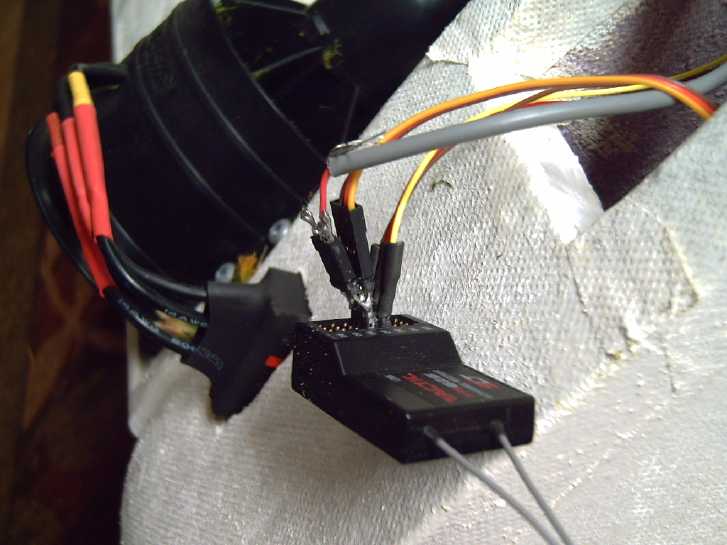 I made a
"splitter" connector so I could connect both
ducted fan motors to the one motor output on the receiver. I cut the
wire from the right (far side) motor and made it a plug and socket
there, so I could plug it into either the receiver or the computer
board connections. After a few fits and starts, I had both motors
running simultaneously when I moved the "throttle" stick on the
transmitter.
I made a
"splitter" connector so I could connect both
ducted fan motors to the one motor output on the receiver. I cut the
wire from the right (far side) motor and made it a plug and socket
there, so I could plug it into either the receiver or the computer
board connections. After a few fits and starts, I had both motors
running simultaneously when I moved the "throttle" stick on the
transmitter.
Tests
[Sorry I didn't take pictures. I took some video but didn't post it.]
I took it out to where I had just mowed the lawn
yesterday, aimed the canard up because then the fans blow air under the
wing, and pulled the throttle lever from 'off' to 'max'. In a few feet
the craft seemed to be up, then it spun around. One fan had sucked in a
load of the fresh grass clippings and was clogged. I removed it clump
by clump with needlenose pliers.
So I took it over to my property line and onto my
neighbor's lawn where there was more space and it hadn't been mowed
recently. There I did a few more runs, with video recording. I made a
very short movie. But was it flying or just sliding across the grass?
It was supposed to be up at least to grasstop height. On reflection I
decided to wait for better results before posting anything. Then it
could be used to show the progress.
A while later I put the bottom on the wing and the tops on
the hulls, but it didn't seem to make much difference to the flying.
Some Observations - Conclusions
All up (with the central fin) the weight was 5235 grams -
over 5 kilograms. The center of gravity was only about 1/5 of the way
along the main wing from the front, hardly behind the step in the hull.
Having the ducted fans on a front canard and able to aim
to blow air under the wing for a quick, easy takeoff seemed to work
admirably. But with the motors and the heavy batteries all near the
front, it seemed notably front heavy in flight. The light rear easily
lifted into the air, but the fronts of the hulls were barely off the
ground - still in the grass - even with the canard pointing well up. If
I leveled the canard the nose grounded. With this design and wing
profile there's substantially more lift toward the back of the wing and
toward the back end than in a typical aircraft, so the weight
distribution needs to be redistributed to account for that. Then it
should fly with the canard more centered, and at a better pitch overall
with the front higher off the ground. I'll have to lengthen the thick
wires and move the heavy batteries farther back.
Even with that, the longitudinal stability seemed good. It
seemed to "float" over the lawn as hoped, albeit with the canard
pointing well up and the fans blowing air under the wing, and the tail
higher up than expected as well. With the weight distribution improved
I expect it'll fly well. The front was so low to the ground, maybe
supported a bit by the grass, that lateral stability couldn't really be
judged.
Without having programmed a means to vary the two motors
separately yet, there was no directional control. The craft inevitably
veered left or right (almost equally, at random), and with no fin in
the middle and the light back end, when it veered it flew diagonally
and then (if I didn't stop it there) spun around. The flights pretty
much all ended that way. (I think I should have made the fin to screw
in. I'm reluctant to glue it on because it'll add a third dimension and
make it quite bulky to store when I'm not using it.)
For a manned version I was hoping the people could sit at
the hull step, which could make a natural "chair". It looks like either
they should be farther back or some other weight (batteries? cargo?)
should be behind them toward the tail end. OYOH, perhaps if that's the
weight and lift distribution the step(s) should be farther back too?
The canard is already almost at the front.
[21st] I cut out the rear foam battery holders. There was enough wire
length that I could move them back a little way. Not as far as I
wanted. But I tried it out, also across a patch with no grass. This
time the tail end didn't rise up into the air. But I still had to keep
the canard pointed full up, and it didn't really fly, but rather slid
along the ground. Was it too heavy for those ducted fans to lift,
powerful as they were? And how could that be improved when the
batteries to power them were half the entire weight of the model? I
hadn't expected the lightweight foam model to be so heavy when I was
making it.
I surmise that it needed to get up more speed to really
fly, but that ground contact was making drag that was preventing the
needed acceleration. But before trying anything else, I should rewire
the batteries and move them still further back so the nose could lift,
and in lifting would make for a steeper angle of attack for takeoff.
Also the tufts of grass sucked into the propellers
couldn't be helping their performance and should be cleaned out! (They
lodge in the stationary blades behind the spinning ones.)
Other "Green" & Electric Equipment Projects
Peltier Cooler
Experiments: Lower Voltages for Greater Efficiency Etc.
Warning: Long boring subject with
a lot of minutae and repetitive findings. If you aren't extremely
interested in the subject, you might just want to look at the orange
table, then skip down to the last paragraphs above "Latest Conclusions"
at the bottom.
[8th] I was planning on checking
out the freezer in my refrigerator. The freezer defrost kept filling
the bottom with ice until water started running onto the floor, at
which point I would pry out the ice layer and it would start over
again. In thinking about emptying the freezer I thought of coolers and
the peltier cooler. (and the peltier chest fridge - but I didn't want
to empty the fridge of whatever junk was in it and bring it into the
house from storage.) The cooler's peltier module hadn't been working
since my camping trip in 2015. Perhaps I had fried the 12 volt module
with 17 volts or so from the solar panel?
(In the end I didn't put any food into the cooler. Instead it
was starting to melt by the time the drain hole in the freezer had been
unearthed, the ice obscuring it thawed, located and un-clogged, with
some liquid observable in frozen milk containers - ouch. I hope they
don't give me migraines! But I had the cooler running before doing the
fridge, and I carried on with some tests.)
I had bought 4 peltier modules a couple of years ago that
were supposed to be better. I got one of them out and installed it in
the cooler. I hooked up a "20 amp" DC to DC converter from my 36V solar
supply, and following that, in line, one of my power monitors (volts,
amps, watts, watt-hours). These were things I didn't have in 2012(?)
when I was originally experimenting. I could adjust the voltage instead
of taking whatever the supply gave, and I could see the currents at
different voltages and as they changed with temperature and time. Also
I have faster reacting digital temperature meters [supposedly] precise
to 0.1°C.
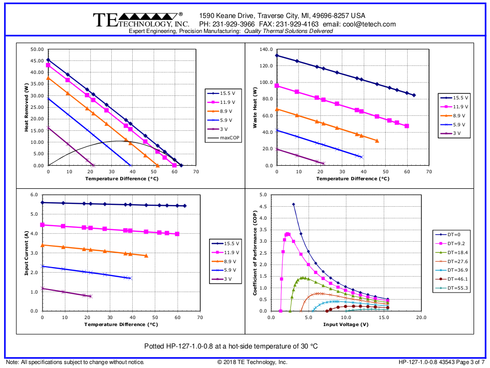
Especially the upper left graph shows the diminishing rate of
performance increase using voltages above around 9 volts,
yet peltier modules are most commonly run at 12-14 volts - double the
power or more of 9 volts - from automotive batteries,
usually via their cigarette lighter plugs. Today a 5$ DC to DC
converter can provide 9 volts efficiently from a higher voltage source.
The [empty] cooler started
off drawing about 4.7 amps at
12.0 volts, which soon dropped to about 4.0 amps/47 watts and
stabilized there as the module's temperatures rapidly changed with the
activation. It seemed to cool awfully slowly. In an hour it was only
down by 2°C from 22.0 to 20.0, although it seemed to speed up just
a bit after that. I turned the juice down to 11.0 volts. There it drew
just about 3.65 amps/40 watts. By four hours it was only down to
15.5°C. I raised the voltage back to 12, but the temperature
started going up marginally. Then I checked the room. The
afternoon sun (Yay, Sunshine!) had been beating through the windows and
the room was up to 23.7. Compared to that, 15.5° was 8.2°
cooler.
When I first bought the cooler I don't remember the time
it took, but I recall that with its original "6 amp" peltier module it
went down to about 4°, probably in about a 16° or 18° room
in winter. 4 is 12° cooler than (at least) 16°. (No doubt the
exact figures are in some old issue of TE News.) Now I'm using 40 watts
and only getting 8° cooler? I know I changed an aluminum cooling
block that the coolness passed through. In all my experiments I suspect
I've made some things in the cooler's cooling system worse rather than
better. It was probably about as well designed and made as it could be
for what it is. (I found the original block after I had reinstalled the
one I made.)
It didn't seem to matter whether it was at 11 volts or 12.
The temperature wouldn't drop below 15.5°. So I thought I'd go to
10.0 volts and see what happened. The lower the current, the lower the
losses and the higher the COP. That doesn't mean it has the same
cooling power, but between 11V and 12V evidently the extra 7 watts was
just a waste. At 10V current was down to 3.35 amps and 33.5 watts. In
an hour or so I checked and it was flashing between 15.6° and
15.3°. (I'm not sure what happened to the digits in between,
because I saw it sitting on 15.5° earlier.) But by now it was 8 PM
PST (and the fridge freezer was fixed). I thought the room had probably
cooled off, but I checked and it still read 23.2° - only 1/2 a
degree down.
The cooler had been running on solar all this time, now it
was getting dim and it was more running on the batteries. So far 12, 11
and 10 volts had all seemed to have resulted in about the same cooler
temperature.
I decided to try 9 volts for a while before I shut it off
for the night. There it drew 3.0 amps, 27 watts. After a while it was
sitting right on 15.3°. Later it hit 15.4, and still later
15.2°.
So I decided to try 8 volts. It did 2.7 amps, 21.5 watts.
The temperatures seemed to jump around a bit: 15.3, 15.4, 15.5 after
some time it seemed to settle on 15.4. It didn't seem to be rising or
falling from there. At 21:30 PST I turned it off. In ten minutes it had
climbed to 16.1, and in half an hour, to 17.5°, so clearly it
wasn't staying down at 15.5° or below without effort. Room
temperature was still 23.0°, so its range since early afternoon had
only been between 23.0 and 23.7° and its differential effects on
the various readings would have been fractions of a degree. There is a
lot of difference between 47 watts and 21.5 watts to accomplish about
the same temperature of cooling!
Volts
|
Amps
|
Watts
|
Cooler Temperature
(Room temp. 23.0 to 23.7)
|
12.0
|
4.0
|
47
|
~15.5
|
11.0
|
3.65
|
40
|
~15.5
|
10.0
|
3.35
|
33.5
|
15.3 - 15.6
|
9.0
|
3.0
|
27
|
15.2 - 15.4
|
8.0
|
2.7
|
21.5
|
15.3 - 15.5
|
Since everything down to 8 volts seemed as good as, or
almost as good as, 12 volts, perhaps I should have tried 7. I suspect
the temperature would have started rising. And I would note that with a
temperature difference from the room of only ~ 8°, lower voltages
would be more efficacious than with higher differences. If 12, 15 or
more degrees can be obtained, 8 volts and below are likely
underpowered. [8.5 to 9V proved to be pretty optimum in later tests
when 11 or 12° drop in the cooler were obtained.]
Conclusions
1. Apparently these peltiers seemed less efficient - they weren't able
to drop the temperature as much as the old one with seemingly similar
input power at 12 volts. Was it because they were smaller? Or was it my
homemade aluminum heat transfer block? (not precision machined flat
surfaces, two joined layers instead of one piece.) [actually I had
missed the warm air guide duct on reassembly!]
2. These tests did seem to demonstrate what I had been unable to show
in
2012: that the performance curves for peltier modules looked so much
better at somewhat lower voltages that they might do just as much
cooling with substantially less power. One might well use two at some
lower
voltage to get higher COP: more watts of cooling power with similar
input watts. The modules being so little
efficient, for portable power use any way to squeeze a bit higher COP
out of them is probably worth the extra initial cost.
I'm still waiting for peltier modules to be developed that
can compete with compressor based refrigerators, even at some cost in
COP and energy use, because they are so much quieter. I haven't
followed
any recent progress but having heard nothing earthshattering (in that
subject area), AFAIK they aren't there yet.
Caveats/Next tests?
There was at least one wild card: as the voltage dropped, the
fans slowed down. That meant the air cooling of the hot side was
decreasing and the cold from the cold side wasn't being blown into the
cooler as well as at 12 volts. And different arrangements of peltier
modules could also be tried.
1. A test I could potentially try was lowering the peltier module
voltages but keeping the fans at 12 volts. Or maybe just the hot side
fan at 12 volts? Any such options would take some rewiring.
2. Still another experiment would be to connect two peltiers in
parallel (electricly and physicly) and try different voltages to see
what cooling could be achieved with how many watts input.
3. The new modules were physicly smaller that the original one. 30x30mm
versus 40x40mm. I could try another one of the original size.
OTOH, this project is a sidetrack! I must get back to the handheld
bandsaw mill kit!
[9th] I went out to the shop and found (a) the manual for the cooler,
which said I bought it June 2012, and (b) an inner air guide that
routed the blown air over the heatsink fins. I had missed it in the
reassembly. That doubtless explains most of the difference in
performance between 2012 and yesterday! I decided to open it up again
and put it back in. Sigh! When I did so I put in a T12V plug and socket
on the peltier module and I left off a grille so I could reach them.
And I remembered that thin pieces of graphite gasket
seem to transfer heat from the module to the heatsinks better than
using "heatsink compound". The gasket is slightly flexible, eliminating
air gaps while itself being a very good heat conductor, whereas the
"heatsink compound" fills air gaps, but is actually a rather poor heat
conductor.
But it took much longer than expected as things just
didn't fit quite right. I guess the original aluminum thermal transfer
block got lost somewhere over the years and in the house move. (Rats!)
It worked somewhat better, dropping by about 10-11°
from the room temperature instead of 8. At any voltage from 7 to 10 it
seemed to work almost the same. The only real difference seemed to be
in the level of power: at 10 volts it used 33 watts and at 7 volts only
17 watts to achieve almost the same cooling.
Then I accessed that plug and powered the module from 7
volts but the fans from 12 volts to keep them running full speed. To my
surprise, the temperature in the cooler started rising instead of
falling. The most likely reason is that blown air is getting through
cracks between the hot side and the cold side. That's probably why it
wouldn't cool as much as when it was in new condition. Apparently I
should have taken extra care to seal it all. I put it back to "single
voltage".
[10th] After running for hours at 8 volts, it was about 11° cooler
than the room (13.8°), which was about 25°. (Wow 25°!)
[14th] I returned to the charge on this morning. I took it apart again
and filled in the cracks as best I could with bits of foam packing and
foam insulation, and put it together again. Then I connected it and set
it to 9 volts. I was disappointed that it didn't seem to cool much
better. Acoording to the graphs for the peltier module (HP127-1.0-.8)
if the warm side heatsink was at 30° and the cold side was at 15,
it should have been removing heat at about 27 watts. It was using 28.5
watts for a cooling COP just below 1. But as before the cooling got
slower and slower long before I thought it should have.
After some hours the room was 22.4° and the cooler was
11.3° - virtually the same performance as before. I am puzzled.
[15th] I tried 10 volts and it got about 12.0° cooler than the
room: 10.3° in the 22.3° room. I finally (perhaps "belatedly"?)
went back and found TE News #54, where I described the cooler when I
bought it in 2012. I noted at the time that it only cooled "by 13 or
14°". That it got down to 4° probably means the room it was in
was only about 17 or 18° - somewhat typical of my old coach house
by the harbour, even in summer. In this room 4 or 5° warmer, the
lowest the original cooler would have got would be about 8 or 9°.
That was with 12 volts and using probably around 50 watts, so getting
to 12° cooler with 10V and 33 watts, or over 11° cooler with 9
volts and 27 watts... or 10.5° cooler with 7 volts, 18 watts... is
probably almost as good as it ever was. And it's a smaller size, 5 amp
rated peltier module instead of a large 6 amps.
The only other thing I can think of to try with the cooler
would be two
of the new peltier modules in parallel, run at say 7, 8 or 9 volts.
Could that give lower temperatures with the same or less power than 50
watts? The other question is how fast any of this would cool food. For
camping, the best idea is of course to have the food cold before it
goes into the cooler.
The other idea would be to drag out the "super
insulated thermoelectric chest fridge", which I still have stored away,
and experiment with it. I have up to three of the new modules I could
put in
parallel. (The fourth one isn't coming out of the cooler!)
More Conclusions
This "high performance" peltier module is probably better
than the ones I was using before. Hopefully it will at least last
longer in use than some of them did. But it's not a big leap. Even if
these are much more durable, without a substantial leap in COP
performance, solid state refrigerators won't replace compresser based
ones except for specialty purposes like camping coolers. (Should I have
continued with my magnetic refrigeration experiments with gadolinium? I
thought I had a better and simpler idea than what other researchers had
come up with. But no! I still think that big leap in peltier module
performance is coming some day. It'll probably be done with intricate
nano scale structures inside the modules.)
Another Idea...
There is one other thing I could try. Some years back,
someone gave me a very sophisticated CPU cooling heatsink.
With the cooler in its regular configuration, even at 7
volts the warm side heatsink was 32° with the room at 22°, so
the peltier module was cooling from 32° to 11° -- not an
11° difference but 21°. And that's assuming the cold side of
the peltier is no colder than the cooler's air, which it will be. So in
fact the peltier itself probably has over a 25° difference between
its two sides, but it's only
getting the cooler down by 11°. Potentially then, if all heat could
be transferred perfectly, the inside of the cooler might be -3°
instead of 11. That's a lot of losses that are hard to reduce, much
less eliminate. (The colder cooler would also lose more coldness
through its insulation, so it would doubtless be somewhat warmer than
-3°... A little above freezing?)
Later: At 8.5V, the heatsink hit 34 to 35° with about
the same room temperature.
Copper conducts heat better than aluminum. (It's second
only to silver, which is only 10 to 12% better and quite costly.) The
gift heatsink has a copper plate against the top of the peltier module,
very closely spaced cooling fins that a small computer fan blows
through, and in miniature the evacuated tubes with water that steams
below room temperature that I tried so hard to make, but could never
get a sufficient vacuum in.
The heat from the peltier heats the copper with the bottom
ends of the evacuated pipes, boiling the water. There's evaporative
cooling, and the steam (which is just above room temperature) rises up
to the top end of the pipes among the heatsink fins and almost
instantly transmits the heat to them. The fan sucks air through the
fins, removing the heat to the air above. The water cools, condenses,
and drips back down in a continual heat transfer process. Assuming the
tiny and mostly horizontal water pipes work right and don't clog
(diagonal sloped is optimum), it is a masterpiece of thermal
engineering.
If the temperature of this clever heatsink is lower by say
5° than a regular aluminum heatsink can attain, that's 5°
cooler the cold side of the peltier can get to. If the cooler was at
5°C instead of 10, it would keep food a lot better. If it could do
it with under about 25 watts at 8 or 9 volts, it might even be
considered economic for a small unit.
Silver?
And having written of it... silver is 10-12% more
conductive than copper, both for electricity and for heat. For
something pretty "ultimate", one might take a pure silver coin, which
is maybe .08 inches thick, make it super flat on both sides, then pound
out the edges to spread them thus:
______________
__/_____Ag________\_ ...but with shallower slopes to expand
the area more where it contacts the heatsink.
| Cu
|
|___________________|
The peltier sits on top, and it's soldered to a larger
copper block underneath. So the heat (or cold) spreads out to a larger
area through the very best metal before it spreads further into the
second best. The finned aluminum heatsink goes under that. (That's the
cold side. The hot side goes the other way up with the heatsink on top.
PS: A copper heatsink should be better than aluminum, but I've never
seen one. And a pure aluminum heatsink would be better than aluminum
alloy, but nobody seems to make one.)
Or would the thin solder layer negate the benefit of the
silver? Probably not -- as long as the solder was thin and it had no
air bubbles. One could
have no copper on the top side. The silver would go straight to the
aluminum heatsink. The copper is just to make a decent thickness of
insulation between the two heatsinks.
But this is all effort for what is after all a pretty
trivial project. I might try out the CPU cooling heatsink. At least
it's cheap. Two 1 troy ounce silver coins is headed toward 100 $C these
days.
[25th] I tried out the CPU cooler. I left the top cover off and it
wasn't properly mounted, but even so it seemed disappointing. The
heatsink fins were so close together that the fan could suck very
little air through them, and it heated up pretty quickly to 30° and
more.
 Then I got out one of the big heatsinks similar to the one I had
used with good results in the peltier module fridge in August 2012. It
only "sort of" fit in, but with the same fan one could feel far more
air movement. It seemed promising.
Then I got out one of the big heatsinks similar to the one I had
used with good results in the peltier module fridge in August 2012. It
only "sort of" fit in, but with the same fan one could feel far more
air movement. It seemed promising.
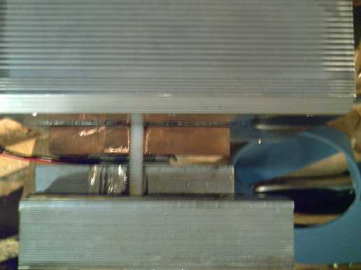
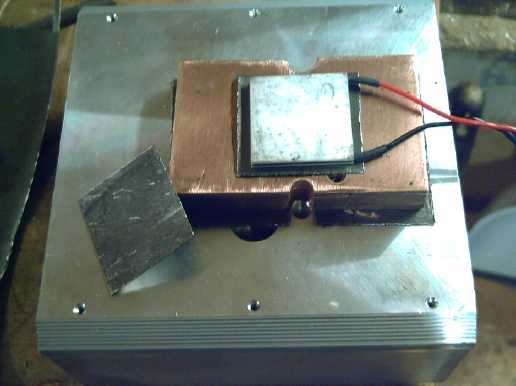
I decided to try everything I could think of (except
silver), and worked late into the night. On the top of course was the
fan and the big heatsink. Instead of putting the peltier module right
under the heatsink, I put in a bar of copper, about 48 by 75mm, 1/2"
thick. The peltier went under that. My thinking was that copper would
absorb heat best, and the heat from the peltier would spread more
quickly into and through the copper than the aluminum heatsink. Then
instead of the 30 x 30 mm peltier, heat would spread into the heatsink
from the larger 48 x 75 mm copper block, overall removing the heat
better from the peltier hot side.
Under the peltier was a 1/2" thick aluminum block of about
the same size as the copper one, then the cold side heatsink in the
cooler. Between each layer was a sheet of thin flexible graphite
gasket. This is better than heatsink grease for getting good contact
and conducting the heat between the two metal or ceramic surfaces. I
drilled and tapped holes and clamped it all together with 1/4" nylon
machine screws, about 2" long. I used nylon bolts so as not to conduct
heat between hot and cold sides, in large
1/4" size because nylon bolts are pretty flimsy.
I tried it out with the peltier at 9.0 volts and the fans
at 12 volts. I discovered that the top heatsink stayed a little cooler
if the fan was raised up off the top 5 mm or so by a couple of pieces
of clothespin. And it took the "edge" off the sound. It sat at about
27.3° - quite a lot cooler than 35! But the cooler didn't seem to
cool very fast. As it was very late I turned it off and went to bed.
[26th] In the morning I put everything at 9 volts and tried it again.
The top heatsink went up to 27.9° -- 2.9° warmer considering
the room was over 2° cooler. So the slower fan certainly wasn't
helping the hot side to stay cool. (It did make it a lot quieter!). It
seemed I had gone to a lot of work for what I thought should have been
a great improvement, instead for not much result.
Hmm... it now occurs to me that there is no real point to
the cold side block being a lot bigger than the module. Maybe that
applies to both sides, and it would be better to have more insulation
instead of a cold block and a hot block 4mm apart, radiating heat/cold
at each other? Well duh, of course it would!
 One more time! I didn't want to chop up the piece of
copper, so I cut two 1/2" thick aluminum pieces, one about 32 by 32 mm,
the other that size and angled so it had a bigger surface on the cold
side heatsink, as per the idea with the silver piece. This time the
peltier went right against the hot side heatsink. I cut hole in the
main insulation to a rectangle, and cut out a block of insulation to
fit that. Then I cut that in half and cut out the middle to fit the
aluminum blocks and peltier module. I did it all more carefully than on
previous tries -- still not a great seal but no big gaps either.
One more time! I didn't want to chop up the piece of
copper, so I cut two 1/2" thick aluminum pieces, one about 32 by 32 mm,
the other that size and angled so it had a bigger surface on the cold
side heatsink, as per the idea with the silver piece. This time the
peltier went right against the hot side heatsink. I cut hole in the
main insulation to a rectangle, and cut out a block of insulation to
fit that. Then I cut that in half and cut out the middle to fit the
aluminum blocks and peltier module. I did it all more carefully than on
previous tries -- still not a great seal but no big gaps either.
It didn't seem to work even
as well as before. Alright!
I've wasted a lot of time on this stupid project to little effect! I
can't even get it to cool as well as when I bought it.
It did seem to show that using lower voltages on the
peltier module made a big difference to the power consumed to little
difference in coldness, but even that is suspect: if it's not going to
get very cold, lower voltages are going to be more effective than if it
actually gets down to refrigerator-like temperatures.
If I'm going to to any more I should either get out my
superinsulated peltier fridge and perhaps use 3 of these little modules
on it, or buy a new camping cooler with the insulation and everything
intact. And maybe it would already have the latest and greatest peltier
module already in it?
Anyway I might as well run it... After 3(?) hours at 9
volts, room 20°, hot side heatsink 27.5°, cooler 12.3°,
3.35 A, 30.1 W. I turned it up to 10V. After not very long, the hot
heatsink was 28.3 and the cooler was up to 12.6°. Good grief!
[31st] I decided to put it back as close to original as I could, and if
it still didn't work very well maybe to buy another one -- or someone
says one can just buy a cooling unit by itself. I looked on AliExpress.
There indeed were some. They looked like about what I had made except
that some were double or triple, 3 fans on each side and 3 peltiers on
one long heatsink. They went up to hextuple units together and hundreds
of watts.
Then I looked at Canadian Tire's website. The "Mobicool"
that I
already have had the best reviews of all their models. (The price has
gone up since 2012.) And some scathing ones. They went from "fabulous!"
to "died in 2 weeks" to "doesn't get very cold" to "drains battery in
no time". No doubt much depended on expectations. We know peltier
cooling uses a lot of power for a little cooling, and I've found they
seem to have have a very limited life expectancy quite unlike most
solid state components. That's better for occasional camping than for
daily use. They seemed to be quite popular in Quebec. Someone actually
got it to the advertised 20°C cooler than the outside, after 9
hours. And they gave a table in their 2015 review:
Température
d'extérieur: 27°
Aprés 2 heures: 13°
Aprés 4 heures: 10°
Aprés 6 heures:
9°
Aprés 9 heures: 7°
(Hmm... Did their outside temperature go
down during the test? Might help explain the exceptional results.
Evidently the manufacturer says it'll drop by 18°.)
At 8.5 volts mine got down to 8.1° in a 19.7° room
overnight - only 11.6° down. The temperature of the air coming out
from the cooling fan and cold side heatsink starts out at about
13°, and the cooler starts cooling quickly. But once the cooler is
down by 9 or 10° from outside, the cooling air was only about
2.5° colder, so about 6.6°. (I still don't see why it doesn't
continue cooling with even just 2.5° cooler air still wafting out.
It seems pretty well insulated. I guess it shows that "super"
insulation is a key to getting good results.) On turning it up to 10
volts, the temperature went marginally up instead of down. So I turned
it down to 7.5 volts instead, where it was using just 20 watts. It went
up a bit more. At 9 volts it went up a little more. But then over that
time, so did the room.
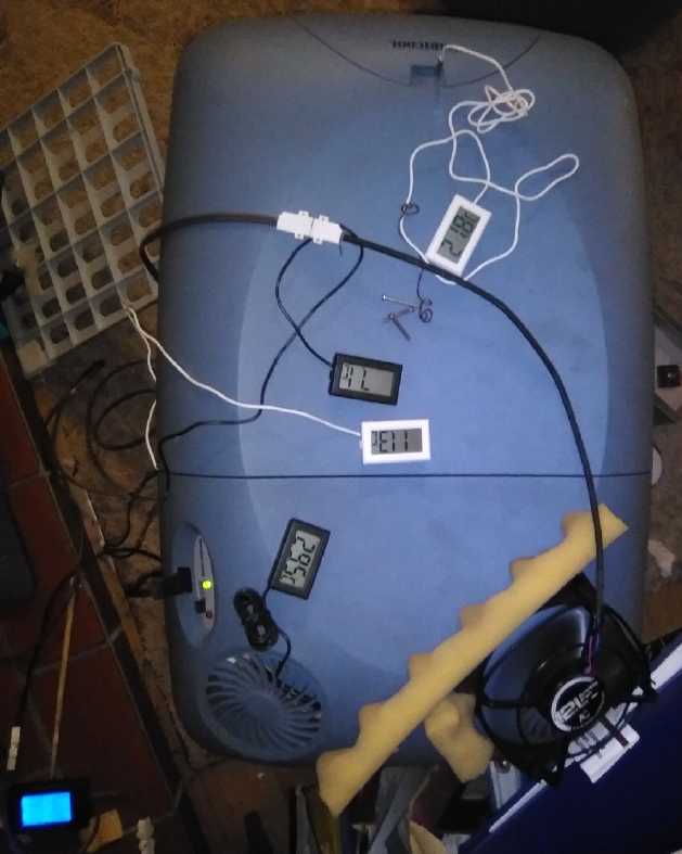 [Sept. 2nd]
Something I finally thought to do was to leave a
temperature sensor directly in the flow of the air coming off the
cooling fan. That way a change in the amount of cooling could
rapidly be measured as a drop or rise in the cooling air temperature
without waiting hours to see what temperature the whole cooler got down
to. I quickly verified what had been taking a long time to figure out.
(It would have been even easier except that while the 3 identical
temperature sensors indicated to .1°C, they would jump around by up
to .3°, giving a slightly different reading each second. This is
not helpful when you actually want to measure such fine divisions.)
[Sept. 2nd]
Something I finally thought to do was to leave a
temperature sensor directly in the flow of the air coming off the
cooling fan. That way a change in the amount of cooling could
rapidly be measured as a drop or rise in the cooling air temperature
without waiting hours to see what temperature the whole cooler got down
to. I quickly verified what had been taking a long time to figure out.
(It would have been even easier except that while the 3 identical
temperature sensors indicated to .1°C, they would jump around by up
to .3°, giving a slightly different reading each second. This is
not helpful when you actually want to measure such fine divisions.)
In some further tests I had sensors on both the cold
side heatsink (or at least the air coming right off of it... was it
actually touching the heatsink? Can't tell.), and near the bottom of
the cooler. Whatever the temperatures (once it was all fairly cold), it
seemed the cold side air was very close to 4°C colder than the
cooler itself. So the peltier had to run at 4° colder than if there
was no difference. (...and why wouldn't 4° cooler air further
cool the unit?...) That large difference indicated to me that perhaps
the cold
side fan wasn't strong enough. If so this was of course largely due to
running it at the lower voltages. Perhaps just that fan should
be run at 12 volts at all times? But then, the warm side heatsink is
even more warm than the ambient temperature - maybe by 7 to 10°.
Latest Conclusions
I knew from the manufacturers' graphs that peltier modules
should work more efficiently at lower powers, and using a DC to DC
converter to easily change the supply voltage, it was a major part of
this experiment to show that. Going between 20 and 50 watts of
input power, from say 8 to 12 volts supply, seem to make very
little difference to the
temperature of the cooling air coming off the cold side fan and
heatsink, or to the lowest temperature attained inside the unit. The
cold
air
temperature
coming
out of the fan hardly seemed to change at
different voltages. In my tests with this module and this cooler as set
up (indeed with several setup variations), about 8 to 9.5 volts
instead of 12 seemed to be a good supply voltage for both low power and
attaining low temperature. It should be noted that the speed of the
fans also changed with voltage. Also somewhat higher voltages might
have worked better than 8-9.5 if greater temperature drop had actually
been attained.
But I still wonder about better optimizing heat transfer from the
peltier module including changing the fans voltages of both fans with a
DC to DC converter. (Hey! I could easily have done that when I had the
unit open! I was after all using two DC to DC converters and could have
tried different fan voltages independently of peltier voltages! NO!
DON'T get it out again! Awrgh!)
This "high performance peltier module" may work a little
better or perhaps live longer than others, but it's not the quantum
leap in performance I'm still hoping will someday soon be made. I think
I'll just put the cooler back in storage and pretend I never got it
out. If you use a peltier cooler for camping, put the food in already
cold to help it out.
Handheld Bandsaw Mill Kit
[6th] I went to Masset and at
Co-op
Home Centre I found some pieces of metal that were about what I needed
for continuing with the bandsaw kit project.
[7th] I had found one inch square steel tube, and I cut two pieces
rather elaborately to make the "P" brackets to hold the cutting guide
rails, bending out outer "ears" and drilling holes to attach the
U-bolts to. I had wanted 1.25 inch tube to fit over the 1 inch square
aluminum guide rails that I had, but 1 inch was the largest. So I cut
out two 3/4 inch rusty steel guide rails from some old assembly I had
lying around. I don't suppose they would slide across wood very easily,
but for sizing things up it all fit together.
I note that the vertical posts really need to be very
straight vertical, and square on, not twisted, to hold the guide rails
properly and so they slide easily in the "d" brackets. ("d"... or "b"
or "p", as seen from the end of the saw.)
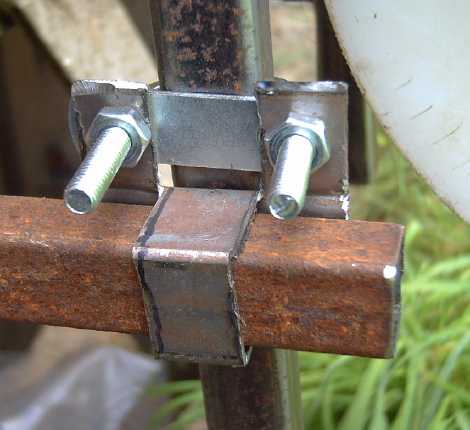
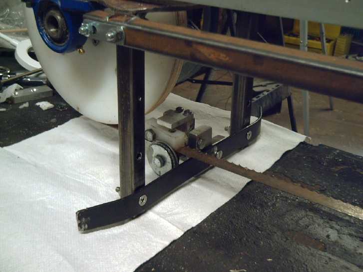
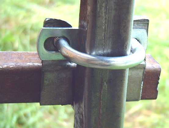 The "d" Brackets to allow the
right assembly to
slide for band
The "d" Brackets to allow the
right assembly to
slide for band
adjustments/replacement without unfastening the cutting depth rails
 The cutting guide rails in place,
rear and
front views, as if cutting the bench.
The cutting guide rails in place,
rear and
front views, as if cutting the bench.
* I noticed that if the plates stuck out past the posts, they could in
theory reduce the maximum cutting depth by about 1/2 an inch. It would
be good if at least the driven side plate didn't. (Oh, it doesn't
matter -
the depth guides prohibit it anyway.)
* And come to think of it, the fact that the driven depth guides stop
below the plate will limit it even more. On the undriven side, the "d"
brackets can be inverted to be "p" brackets so the guide bar can go
above the plate. I tried inverting the brackets and found the ears
stick into the potential cutting width. It can still be done on the
undriven end for cuts less than absolute maximum width, but not on the
driven end. So there's no point putting "p" brackets on the driven end.
If no welds are in the way of the driven end U-bolts, potential cutting
depth measures about 6 inches. With a 2 inch guide board on top of the
piece being cut, that makes it 4 inches. That will have to do. It's a
lot thicker than I could cut with the prototype, which
was only about 2 inches with a 1.5 inch guide board.
* I had also noted that if the hollow of the driven side posts went
through the plate, supports could be inserted to mount it to a bench as
a shop bandsaw. If the undriven side posts did also, a better, stronger
support frame might be devised.
* [9th] In fact, the posts should go right through the plates and end
maybe an inch above them. Then when they are welded on, the welds can
be on the top of the plate (eliminating the bit about welds obstructing
U-bolts in the remark two up from this one) and without danger of
getting weld material obstructing the insides of the posts.
* I'm thinking if the posts are going to be used to affix the saw to a
workbench as a shop bandsaw, having vertical reinforcements will be
necessary, and having them on the top of the plate will also
keep them out of the way of the guide bars.
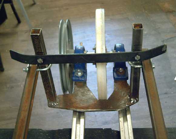 [9th] I cut a strip for an
end stop. I decided to bolt it on instead of
welding it. I placed it I hope far enough above the band that it'll
never hit it. Oops, the bolt heads are in the way! It can still be
done, with flat head bolts. I didn't use a lower end stop below the
band on the prototype. If there is one, it would have to be removable
to change the band. I'm not sure there's much advantage to having one.
[9th] I cut a strip for an
end stop. I decided to bolt it on instead of
welding it. I placed it I hope far enough above the band that it'll
never hit it. Oops, the bolt heads are in the way! It can still be
done, with flat head bolts. I didn't use a lower end stop below the
band on the prototype. If there is one, it would have to be removable
to change the band. I'm not sure there's much advantage to having one.
I also consider that if it's used as a bench bandsaw, one
will want a more solid little "table top" there instead of an "end
stop".
[12th] I had been making pieces for the
band tensioning and alignment
mechanism. Then I cut a band shorter and silver soldered the ends
together, since the saw couldn't extend as wide as I had had the
prototype. It needed at least 4 inches shorter bands. It all looked
very promising and straighforward, but when I put it all together it
didn't work as smoothly as I had hoped. The band kept falling off the
right wheel and I couldn't get the wheel's axle straight. Finally I
took the "pillow block" bearings off. They were supposed to be free to
pivot in any direction, but one of them was seized up, and so it
wouldn't change its angle to align the shaft. I freed it up enough to
add some grease, but it still wouldn't pivot freely. I hammered the
shaft to right angles by eye and put it all back together. Now I could
at least adjust it through the "best tracking" area and the band stayed
on.
But the two tension/alignment adjustment bolts were
unexpectedly hard to turn in spite of everything I tried, and I ended
up using a wrench instead of turning the wing nuts by hand. The answer
may just be bolts with bigger wing nuts for a stronger grip. (eg, from
the many selections available at JW Winco?) A better answer would be to
figure out how to maintain proper alignment, but there's only one bolt
to attach the threaded end to and the pull is off center, so the
horizontal can shift a bit, and with one the vertical is a little off
too.
I was concerned about the weight, which proved to be about
26 pounds. The saw (the motor) was about 8 pounds, making 34. The
prototype was 40 pounds, and I wanted to be there or lighter. That left
6 pounds for everything else. There were still the band guide wheel
assemblies to mount, and the body sheet pieces to mount the motor and
to guard against accidently touching the band. (Anything else?)
On the 16th and 17th I got the band guide wheels mounted.
I figured out an arrangement where the right side one, which has to be
able to move depending on the width being cut, could be bolted to just
one of the main rails instead of both. I bolted the left side one to
the edge guide. (which might also be called the "side guide" or "end
stop" or something.)
[18th] I had thought to weld the edge guide to the posts just above the
cut line. If it was below the cut the blade band would be encircled by
the body, the posts and the guide, making it very difficult to change.
But I was seeing problems with having it above, too. First it got in
the way of the cutting depth adjustments. The problem looked insoluble
without making it a mechanical nightmare. Second if perchance one was
cutting very thin boards (guitar tops or backs, veneer...) the guide
could actually be too high up.
I finally decided that I would have to bolt the edge guide
below the cut line. One bolt would have to be removed and the other
loosened, and the edge guide swung out of the way, to change the blade.
I had hoped to make blade changing dead simple. One could potentially
have two edge guides that didn't meet in the middle, one welded to each
post. The blade could be slipped in and out through the gap. In fact,
they could be at the exact level of the blade. But it might be
something of an additional nuisance when cutting a log as one passes
knots and irregularities. Something to try out later perhaps. For now,
I moved the edge guide to just below the cut line.
Changing the edge guide of course meant changing the left
band guide wheel mounting that I had just attached to it. I cut a new
aluminum block to hold it and managed to use the same holes in the edge
guide.
[23rd] My silver solderings being unsuccessful, I welded a bandsaw band
together with the TIG welder. It didn't last either. I looked on
youtube. You
need a special welder to weld bands. Somehow it melts the actual band
metal and no weld material is added. Everybody else who didn't have one
was using silver soldering. Why did my 2016 silver soldered band work
fine, but now this one just breaks apart no matter how many times I
try? It is getting ridiculous that the project is about to stall for
want of a good blade! I guess I should order a few.
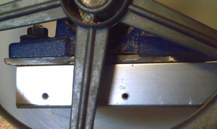 [24th] The weld did last
long enough to change a couple of things. I
had discovered was that if one drilled a regular 5/16 inch bolt hole
and put a 5/16" carriage bolt into it, the square part of the bolt
wouldn't
fit through the hole. And because of that, things bolted to the main
aluminum frame bars weren't tight and would slide along the bars. So I
was putting washers in that seemed to fill the gap. But, if one drilled
a .4 inch hole, the square of the carriage bolt fit though it. Then the
part would bolt solidly on.
[24th] The weld did last
long enough to change a couple of things. I
had discovered was that if one drilled a regular 5/16 inch bolt hole
and put a 5/16" carriage bolt into it, the square part of the bolt
wouldn't
fit through the hole. And because of that, things bolted to the main
aluminum frame bars weren't tight and would slide along the bars. So I
was putting washers in that seemed to fill the gap. But, if one drilled
a .4 inch hole, the square of the carriage bolt fit though it. Then the
part would bolt solidly on.
So the driven side plate and wheel got
.4" holes and attached solidly to the bars (eliminating washers, nuts
and extra
spacings).
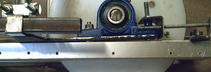 The other side plate got two of the small
holes to let it
slide for adjusting the tension and tracking, while the other two bolts
to hold the "pillow block" bearings became flush flatheads in the plate
that didn't go into the frame bars at all. There's a slight diagonal
tilt to the plate. It shouldn't matter.
The other side plate got two of the small
holes to let it
slide for adjusting the tension and tracking, while the other two bolts
to hold the "pillow block" bearings became flush flatheads in the plate
that didn't go into the frame bars at all. There's a slight diagonal
tilt to the plate. It shouldn't matter.
Something better has to be
done with the tensioning and
alignment screw blocks. There's nothing to keep them from twisting a
bit, and then the threads don't turn smoothly (to say the least). Yet
they need to be off-center to miss the bearings. How can I keep them
straight but also simple? [25th] I threaded a 1/4" hole and put a short
bolt through it. It can be turned against the bearing block to keep the
piece straight[er] against the pressure of the band tensioning screw.
It's
still hard to turn, but not as bad.
I got the band guide wheels attached, but the left one
didn't line up very well. I marked holes to change it.
When the guide wheel, the motor mount and the safety
guards are done it should be usable and I could try it out. I had hoped
to get there before the end of the month. (I myself want to cut certain
6" x 6" spruce beams each into a 2" x 6" and three 2" x 4"s, and I have
no other saw to easily do that!) But I had to get the roof
properly on the greenhouse before any strong wind blew the loose panels
away, and some nice days came along on which to do that.
Greenhouse
&
Gardening
Pea Shelling Tip
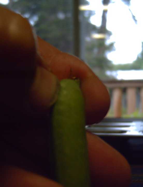 Depending on the variety,
peas ready to pick should be pretty much cylindrical, and squeezing
them they won't readily crush down thinner. ("Arrow" won't be
cylindrical. "Laxton's Progress" (A.K.A. "Tall Telephone Pole") or
"Little Marvel" will.) Anyway you know it's too soon if the peas are
still tiny inside. When the pod starts turning a duller color and
drying out, they start to lose their sweetness and are headed for being
dried peas or seed for next year.
Depending on the variety,
peas ready to pick should be pretty much cylindrical, and squeezing
them they won't readily crush down thinner. ("Arrow" won't be
cylindrical. "Laxton's Progress" (A.K.A. "Tall Telephone Pole") or
"Little Marvel" will.) Anyway you know it's too soon if the peas are
still tiny inside. When the pod starts turning a duller color and
drying out, they start to lose their sweetness and are headed for being
dried peas or seed for next year.
I have long shelled peas by grabbing one end and trying to
"unzip" one of the strings. Once a string is gone, that seam opens
easily. Once a seam is open, the peas are easily pushed out into a bowl.
This year I found a better way. At the
most convex part of the seam at the flower end, dig in a thumbnail just
beside the seam (left thumb just to right of the seam or right
thumb just
to the left). With the other thumb below the first, or if necessary
also using the
other thumbnail, usually the pea can be pried wide open. Don't bother
about the strings.
Late discovery: It doesn't work well if your thumb
nail is too short! It has to dig right through the pod to the inside,
or else the pod separates into layers when you pry on it, instead of
opening.
Fruit
 With no
apples, pears, apricots, black currents, josta berries or strawberries
and just a few cherries, the only bright spots in the fruit department
were some raspberries from the canes planted this spring, and
blueberries from my bushes by the house. (They have been living,
growing and
producing now that I realize blueberries need tons of water.)
With no
apples, pears, apricots, black currents, josta berries or strawberries
and just a few cherries, the only bright spots in the fruit department
were some raspberries from the canes planted this spring, and
blueberries from my bushes by the house. (They have been living,
growing and
producing now that I realize blueberries need tons of water.)
But I think my surmise was right that the strawberries
that grow great and have great flowers - but which never develop into
berries! - are just a bad variety, at least for around here: Two of the
three I bought in pots in July, still in the pots, are working on their
second crop of berries. One looks about ready. And they have runners
dangling out everywhere. What I need to do now is thoroughly get rid of
all the roots of the old ones, preferably throughout the entire garden
(where they have spread profusely), and plant these and their runners.
I started on that in early September. It's hard work, made
more difficult by rocks around the edges, which are especially hard to
weed. So I'm carting off the rocks first. (to where?) Well, it all
needed doing anyway.
Small Berry Picking Tools
Salal is a bit of a difficult berry to pick. It's pretty
soft, and sticks onto the stem hard enough that one often squashes the
berry trying to pull it off. One's fingers soon get soaked in juice
making the whole thing somewhat unpleasant.
On September 8th (yes, before finishing this newsletter) I
took a regular table fork and a small square plastic container outside,
and tried picking salal berries (obviously by appearance related to
blueberries, tho perhaps not too closely) by getting the fork tines
around the stem and pushing it to get the berry off, with the container
underneath to catch it. It seemed to work well. Then I found I could
get it farther up the branch and strip off a whole small cluster of
berries. In ten minutes I had a couple of cups of them. The small
container was now losing them over the edges as I walked around so I
quit.
I thought this was exciting enough that I mentioned it to
a few people. Gerald said there was already something for that that had
tines, with a container to catch the berries built in. Someone had
mentioned a "berry rake" or something before too, but I had thought it
was something for wholly larger berries. But Gerald said it was good
for huckleberries, which are even smaller than salal berries, tho they
come off the stems much more easily.
I looked up "berry rake" on AliExpress, and (sure enough)
found two models of "berry picker comb plastic blueberry rake scoop".
They're both plastic and I doubt the durability of the "comb" of tines,
but I ordered both. The fork and container had made picking much faster
(and nicer without getting fingers wet with juice), and these might be
even better. And good for huckleberries too? Worth a few bucks to find
out!
Corn & Greenhouse
[5th] I had been pleased with the growth of the corn in the greenhouse
until almost August, when I realized that it had grown tassels but not
a single ear anywhere! At first
I thought they would come along, but there was in fact no sign of any
forming. After posting TE News #158, I thought: Why? The only
answer that came to two minds was: not enough light. That
horrible "Solexx" supposedly translucent material supposedly made for
greenhouses, akin to coroplast but still less transmissive, simply cast
a big dark shadow underneath. Ever since I had made it, I felt it was
just too dim
in there. And I started to realize that the corn stalks seemed thin -
somewhat tall and spindly, like lettuce sprouts growing up and up until
they fall over when they don't have enough light. Last year, by
protecting the corn with plastic until it was well over knee high, I
got cobs with edible corn (certainly nothing fabulous!) in spite of
August being incredibly cloudy. (...just 205 KWH solar energy instead
of around
300!) That it wouldn't form cobs this year would seem to suggest that
the "Solexx" let through even less sunlight than last year's clouds.
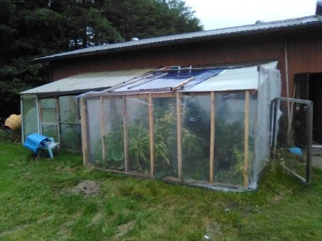 I
had hoped to make my own greenhouse panels out of
recycled transparent plastic, maybe next winter, but "no corn" after
all my work expanding the greenhouse and prepping everything carefully
- yet
another crop that seemed to be growing beautifully except no crop - was
just too much. The next morning I drove to Masset to Coop Home Centre
and bought 12 sheets of PVC "ripple" greenhouse plastic. I took down
the
three 4 foot by 12 foot "Solexx" sheets and just threw 7 of the new
sheets up on top to replace them for the moment. (That left a 2'x2'
hole, but I needed it for the ladder anyway.)
I
had hoped to make my own greenhouse panels out of
recycled transparent plastic, maybe next winter, but "no corn" after
all my work expanding the greenhouse and prepping everything carefully
- yet
another crop that seemed to be growing beautifully except no crop - was
just too much. The next morning I drove to Masset to Coop Home Centre
and bought 12 sheets of PVC "ripple" greenhouse plastic. I took down
the
three 4 foot by 12 foot "Solexx" sheets and just threw 7 of the new
sheets up on top to replace them for the moment. (That left a 2'x2'
hole, but I needed it for the ladder anyway.)
I do recognize that it might be too late - if not much too
late - for this year, but I wanted to try. Perhaps with more light they
could still grow ears for a late crop? Unfortunately again, the
brightest part of the summer and the longest days are already over.
On the 15th I noted a few ears just starting to emerge. By
the 24th, a few more. I rubbed pieces of the tassels onto the silks on
the ears to pollinate them. If
I get any corn, it's likely to be pretty late in the fall!
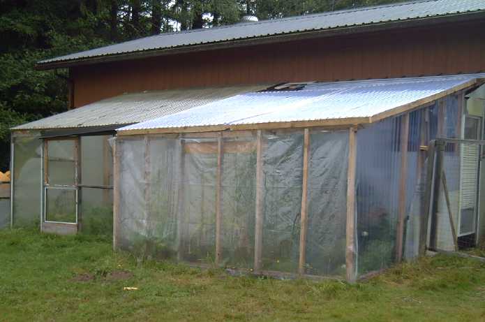 Late in the month I cobbled together a roof that wouldn't blow away
with the first good wind that came up, with two frames 6 feet by 10
feet that could be screwed down to the supporting boards. These could
be taken anywhere. The whole is by no means finished, but it's
functional for now. Perhaps I'll find a sunnier spot for the
greenhouse, and this would make it easier to move. ...Or maybe I should
have 3 or 4 of the trees shading it worst in the afternoon taken out.
Late in the month I cobbled together a roof that wouldn't blow away
with the first good wind that came up, with two frames 6 feet by 10
feet that could be screwed down to the supporting boards. These could
be taken anywhere. The whole is by no means finished, but it's
functional for now. Perhaps I'll find a sunnier spot for the
greenhouse, and this would make it easier to move. ...Or maybe I should
have 3 or 4 of the trees shading it worst in the afternoon taken out.
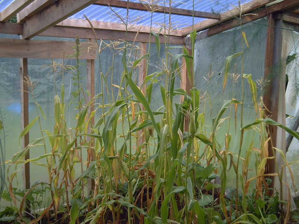 "Peaches and Cream Early" corn.
Hah! May, June, July, August, September
"Peaches and Cream Early" corn.
Hah! May, June, July, August, September
I've been having a few good beans, cherry tomatos and
yellow zucchini,
but failing some more sunshine soon, or actually heating the greenhouse
somehow, the corn, tomatos larger than "cherry" and carrots are all
going to be duds.
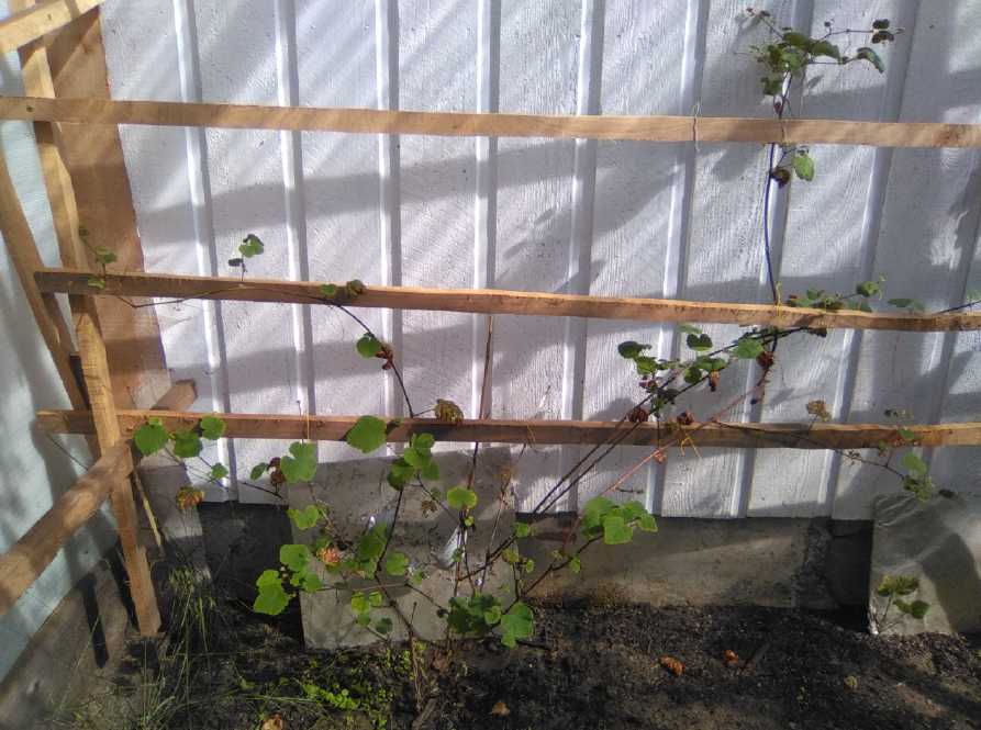
Oh well, I can get an earlier start next year, and spend
less time making
some less major improvements to the greenhouse (like complete concrete
footings to help keep
the slugs out -- around the garden, too! And perhaps I should get some
of those automatic louvers to open a section of the roof for when it
gets hot?
Misc.
[11th] I picked some more peas, shelled them and froze them. Cumulative
total of the 12 foot long row with 6 foot tall 1 inch chickenwire: 1.27
Kg. With 2 inch chicken wire, birds land on it and eat the peas. Ditto
with horizontal construction wire. But the 1 inch chicken wire seems to
keep them away. I don't like the "fish net" pea netting. I hate
throwing it out after one use, but it's a hassle trying to clean the
old
vines out of it to reuse it.
The plants were actually about 8 feet tall (or even 9) but
then keeled
over at the top of the wire. Maybe I'll go for a foot taller fence next
year,
or even two. But there's a limit ot how high is convenient to pick,
too. The second row of peas was ready to start harvesting just as the
first was petering out, so I
may have about 2.5 to 3 Kg in the freezer by the time they end. But it
didn't grow as tall and thick as the first row.
(By early September I had 2160 grams of peas in the
freezer, and I had of course eaten some. There are a couple more
pickings out there.)
 First row of peas Aug. 22nd
 Second row of peas about end of
month.
Second row of peas about end of
month.
Some are fat, round and ready to pick.
In a few, sunlight shining into the pods shows the tiny peas inside.
 The leaves of
the quinoa were bug eaten almost to skeletons. I hope the flowers are
able
to develop good seeds.
The leaves of
the quinoa were bug eaten almost to skeletons. I hope the flowers are
able
to develop good seeds.
Another week of good weather in September should have
turned them red, but on the 5th I cut them and took them inside before
they went mouldy in the rain. Hopefully there's some good seed in them.
The 5 potato patches were
having mixed luck. The ones in
the compost looked best. But they'll all have potatoes underneath!
After a slow start, yellow zucchinis were starting to
produce.
I've also had some beets and some chard, and some cherry
type tomatos.
 Two close rows of (mostly) beets,
and one of
bush beans beside it.
Two close rows of (mostly) beets,
and one of
bush beans beside it.
Scarlet runner pole beans (along with all other beans I
planted) made a very slow start, and some were eaten by slugs. Finally
by the end of the month the brilliant red flowers were starting to form
beans. Hopefully in September they'll have a good crop. (One of the
posts fell over - ug!)
I tried growing carrots in a raised bed in the garden, and
in the greenhouse. I think the first seeds I used were too old. But
they kept dying once up. Perhaps I wasn't watering them enough.
Gradually the raised bed got overshadowed from all sides, but not
before I had given up on the carrots anyway. One row in the greenhouse
has a few that are at least bite size.
A lot of stuff seems really late this year in spite of
much sunshine. Stuff just doesn't seem to grow as fast up here as
farther south. But then, it snowed in April and wasn't at all warm
until June, which is usually the time for "mid summer" plantings.
Someone else had fabulous cabbage (started indoors in the spring) and
carrots.
My gardens look pretty wild. I don't have time to do much
weeding and care amongst all my other projects, and I tend to leave
"past due" plants to make seeds.
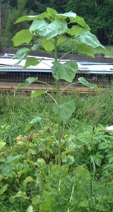 A sunflower. Taller than me, but
one
A sunflower. Taller than me, but
one
of two with no flower by September.
Here's a couple of volunteer squash of some sort. They took over a row
of beans. By the end of the month, for all the vine and flower growth
just has one tiny squash just starting.
In the same row something came up that looked like some
sort of grass family plant. Early consensus was that it must be corn.
But as it developed, I can say I've never seen anything like it. This
is what it looked like at the start of September:
 On the 25th I went out in
the rain and plucked out the
garlic. I had meant to do it a few days previously. The tops had pretty
much died off and turned brown. It had grown well and was a great
harvest, best garlic I've grown. (and someone else planted it!) Fall is
the time to plant cloves for new garlic next year, so
it grows for nearly a year, mostly just growing some roots over the
winter.
On the 25th I went out in
the rain and plucked out the
garlic. I had meant to do it a few days previously. The tops had pretty
much died off and turned brown. It had grown well and was a great
harvest, best garlic I've grown. (and someone else planted it!) Fall is
the time to plant cloves for new garlic next year, so
it grows for nearly a year, mostly just growing some roots over the
winter.
Honey Bees?
Hiveworld hadn't shipped my bees this spring, but they
said
I'm on the list for next spring. People complain that only New Zealand
and Haida Gwaii are still free of the varoa mites that have spread to
everywhere else and plague both wild and kept bees. They say I
shouldn't bring
bees from anywhere but New Zealand to here. But the common "Italian"
type brought from New Zealand (and apparently also from Australia - are
there no mites there?) doesn't fare very well here, as previous
attempts
to keep bees have shown. I want bees that suit the climate and mixed
vegetation. This definitely isn't the prairies, hot and dry in the
summer with fields of alfalfa and canola stretching off into the
distance. Kamil, the experienced beekeeper I know, says there must be
varoa mites here - they're everywhere, in wild bees as well as
"domesticated". And the Carniolans are brought in from Chile. Do they
have the mites in Chile?
One day in late July I saw a honey bee on a flower. A
small blackish one, but with that distinctive "honey bee" look to it. I
was unaware that there were any honey bees on these islands besides
Al's Italian ones in Sandspit, but I was pretty sure it was one. Some
people told me there weren't. On the
7th I mentioned it to someone who would probably know, if anyone would,
and she told me yes, there were wild ones around!
Honey bees aren't native to the Americas, much less to
Haida Gwaii, so I presume these must be descendants of some brought
here by settlers a century ago. The fact that they have survived this
long even in small numbers probably means that they are a good breed
for this cooler climate, such as the Carniolans I've been after.
This might change the picture. If I could get some
"native"
honey bees, the threat of potentially bringing an
unwelcome bee bane to the island would be eliminated. They were
obviously acclimatized enough to survive here. (Although, I doubt
they're really thriving, or we'd see a lot more of them.) Once they
were in my luxury bee condo they would surely stay. And thrive. How
could they find it? My place must surely be at the extreme edge of
their range, since I've only seen one honey bee in four years.
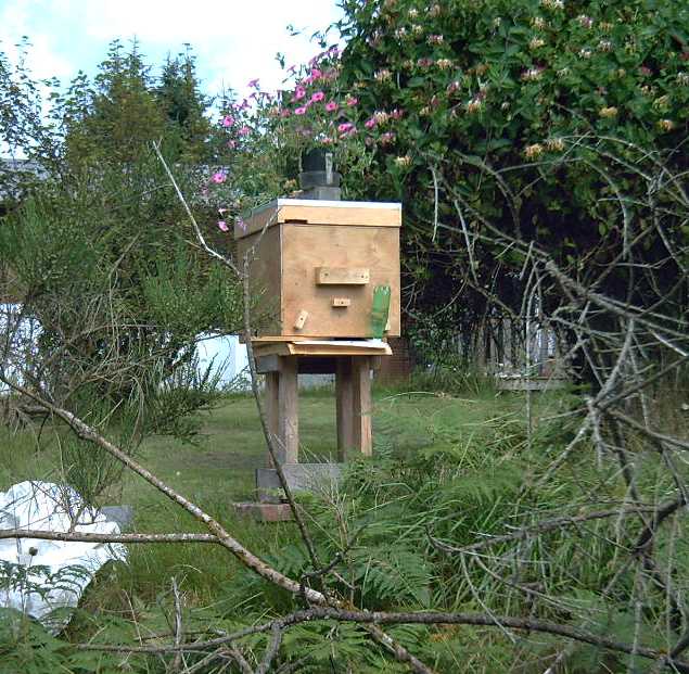 I had just
taken the hive apart and carried it all over
near the house, and was about to put it inside for the winter. (Why
have it out in the weather when it was empty?) I carried the pieces
back to the prominent place on the lawn that I had picked and put it
together again. Kamil said to use a five frame "nuc" (nucleus hive) so
they wouldn't be intimidated and have to warm a large hive when their
numbers were small. I had made mine so spacers and extra insulation can
be inserted to make it into a smaller space, and since it was extra
tall, I reduced it to four frames. I mixed some sugar and water, with
which beekeepers feed their hives in winter, and set it at the
entryway. But that had no petals and no scent. What were the chances
that it would be found, and revisited even if it was?
I had just
taken the hive apart and carried it all over
near the house, and was about to put it inside for the winter. (Why
have it out in the weather when it was empty?) I carried the pieces
back to the prominent place on the lawn that I had picked and put it
together again. Kamil said to use a five frame "nuc" (nucleus hive) so
they wouldn't be intimidated and have to warm a large hive when their
numbers were small. I had made mine so spacers and extra insulation can
be inserted to make it into a smaller space, and since it was extra
tall, I reduced it to four frames. I mixed some sugar and water, with
which beekeepers feed their hives in winter, and set it at the
entryway. But that had no petals and no scent. What were the chances
that it would be found, and revisited even if it was?
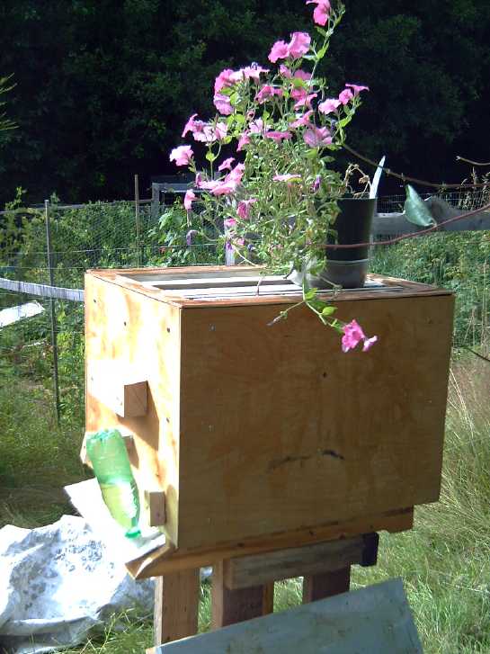 Then I thought
to use honey instead. I took out a big jar
and smeared it all over both sides of the four frames, then the landing
area and entrance, then all over the hive walls and roof outside. Honey
at least has a bit of scent, the hive was right by my big honeysuckle
bush that should already be attracting bees if there were any around
(the big hoverflies, and the few bumblebees, love it!), and what would
honey bees love more? If
anything would make them take notice and fly over to find it, honey
should. And if, having found it, anything could convince them to come
back and sooner or later in a swarm with a new queen and come to stay,
that should
be it! Later I took the roof off the box so they could more easily look
inside, and I took my pot of pink flowers and set it on top as a
further attraction.
Then I thought
to use honey instead. I took out a big jar
and smeared it all over both sides of the four frames, then the landing
area and entrance, then all over the hive walls and roof outside. Honey
at least has a bit of scent, the hive was right by my big honeysuckle
bush that should already be attracting bees if there were any around
(the big hoverflies, and the few bumblebees, love it!), and what would
honey bees love more? If
anything would make them take notice and fly over to find it, honey
should. And if, having found it, anything could convince them to come
back and sooner or later in a swarm with a new queen and come to stay,
that should
be it! Later I took the roof off the box so they could more easily look
inside, and I took my pot of pink flowers and set it on top as a
further attraction.
I don't know what the odds are - given that I've only seen
(or noticed) one honey bee in four years they seem slim - but if it
works it would be fabulous! (On the 11th I saw another one. And I saw a
tiny black bee eating the honey on the hive. I put a screen over the
hive: the bees can look in, but they'll have to use the front door to
go in! On the 12th I saw a honeybee in town. It was the more usual size
and
color. I wonder if Queen Charlotte is within the 10 Km radius bees are
said to forage from Sandspit where Al keeps them? Or does someone in or
near town who is very quiet about it also keep them? At the end of the
month I saw one or two more - one in my greenhouse.)
I watched a couple of "How to catch a swarm" videos on
Youtube. One said to try in April through June. That seemed
discouraging in August - it meant waiting until next year. I would
either have to cancel my order with Hiveworld and take my chances, or
import the bees. But then I remembered my mom keeping bees on the
acreage at Fanny Bay BC in 1973 or so when I was a teenager. Being
afraid of being stung, I pretty much avoided them and paid them little
attention. But I remember they swarmed and there was a huge mass of
them hanging from a branch in a tree. It seemed to me it was late July
or August. I phoned her, but she couldn't remember the month. (I also
remember they only lasted one summer and they died of not being fed
enough in the winter. She says it was two years and the second winter
that they died. Since there was no such thing as e-mail back then or
even home computers, neither of us have any records to jog our
memories. She doubtless remembers better than me. And there were no
"how to keep bees" web pages or videos... might the library have a book
on it? How fast the world is changing, yet so gradually we don't think
of it day to day!) Anyway, maybe it was possible some might still swarm
this summer? Seasons on Haida Gwaii are usually later than elsewhere
anyway.
(Later I was talking with my brother and he thought they
had swarmed in June or July. He also remembered they were only there
for one year. That also means they swarmed within a month or two of
getting them, which jibes with my memory. He said that he later in the
summer found a hive of honeybees living in a hollow log by the creek,
which he surmised were the swarm.)
Two videos also said that beeswax or bee propylis, "lemon
grass oil", and hive frames that already have comb will attract bees. I
had a bar of beeswax. I shaved some off the end and sprinkled it into
the hive. [12th] I remembered a wired frame Al had given me that bees
had built just a few hexagons of comb on. I removed an empty plastic
one and put that in. Lemon grass oil evidently has an almost identical
scent to a pheromone queens give off related to swarming or something.
So I went into town the next morning [12th] and bought some at the
health food store. I sprinkled a few drops of it into the hive through
the top screen. (Too much is bad, apparently) I don't think there's
much more I can do now except wait, hope, and occasionally smear on
some more honey to replace what the various flies, hoverflies, wasps
and tiny bees have eaten. Evidently a bee swarm will stay in a tree
branch for a day or two or three while scouts go out looking for a
suitable hive spot. IF there's a swarm, and IF the scouts find my hive,
there's every chance the "SOLD" sign will appear on the front lawn of
the bee palace.
[15th] There is some activity around the hive. Yellow jackets (wasps,
not "Gillette Jaune" Parisians), which I seldom see around here, are
showing up in
quantity, I think to just eat the honey. Now if only they were honey
bees!
[September 1st] With having seen just a
few bees now, I have a high
expectation of luring in a swarm in the spring. How could they resist
such luxury accommodation? I finally decided to gamble and cancel my
"nuc" order
with Hiveworld and to just buy a bunch of beekeeping stuff with the
credit. It seems too late for this fall, but if I can capture a swarm
in the spring, the ones I get will surely swarm again sometime and I
can
have another hive ready - more honey, or get more of them going for
other beekeepers. (I put in an order for A.K.O. beekeeping stuff on
September 6th.
Enough to make a honey super and another "bee barn" hive.)
Electricity
Generation
My Solar Power System
Daily/Monthly/Yearly Log of Solar
Power Generated [and grid power consumed]
(All times are in PST: clock 48 minutes ahead of sun, not PDT which
is an hour and 48 minutes ahead. (DC) battery system power output
readings
are reset to zero
daily (often just for LED lights, occasionally used with other loads:
Electric car, inverters in power outages or other 36V loads), while the
grid tied readings are
cumulative.)
Solar: House, Trailer, (DC@house) => total KWH [grid power
meter
reading(s)@time] Sky conditions
Km = electric car drove distance, then car was charged.
July
31st 2036.65, 877.59,(.45) => 9.46 [86001@19:30] More of the
same.
August
1st 2044.12, 881.88,(.00) => 11.76 [86018@21:30] Some
decent
sun today ; 21°!
2d 2049.77, 885.12,(.00) => 8.89
[86027@20:30]
3rd 2055.59, 888.71,(.00) => 9.41 [55Km;
86042@20:00] Sunny only occasionally but hit 21°!
4th 2059.00, 890.91,(.00) => 5.61 [86052@20:00]
Mostly
wind & rain. Later sun came out.
5th 2062.77, 893.16,(.28) => 6.30
[86068@20:30]
6th 2067.97, 896.17,(.00) => 8.21
[86078@21:30]
Cloudy. Cool. Totally unlike most of western North America.
7th 2073.57, 899.65,(.00) => 9.08 [66Km;
86092@21:00] Rain squall. Clouds. Bit of sun now and then.
8th 2080.15, 903.58,(.40) => 10.51 [86102@20:30] Nice
sunny PM (DC system was used for Peltier cooler tests)
9th 2088.50, 908.18,(.00) => 12.95 [86108@20:00] More
Sun than Clouds
10th 2097.76, 913.53,(.51) => 15.12 [70Km; 86124@21:00] Sunny and
warm! 23+° (mor Peltier tests from DC)
11th 2107.05, 918.95,(.00) => 14.75 [55Km; 86140@19:00] Yay, another
beautiful day!
12th 2116.50, 924.39,(.27) => 15.16 [50Km; 86154@21:00] Sunny again!
13th 2123.77, 928.51,(.00) => 11.34 [90Km; 86175@20:30] Sunny until
eve but hazy (jet trails?), then cloudy w. sprinkles of rain. Car
thermo. said 25°(!) toward Port Clements @ ~12 Ante Meridian PDT
(about 1-1/2 hours before noon)
14th 2126.78, 930.32,(.33) => 5.15 [55Km; 86192@19:00] Much
cooler (~18°), cloudy.
15th 2132.56, 933.62,(.60) => 9.68 [86200@19:30] Cloudy
until mid afternoon.
16th 2139.08, 937.60,(.42) => 10.92 [55Km; 86210@20:00] Sunny PM
again.
Still cooler.
17th 2148.01, 942.52,(.39) => 14.24 [60Km; 86226@20:30] Sunny! (But
not so
warm.)
18th 2151.73, 944.81,(.29) => 6.30 [85Km; 86242@19:30] Is
summer
over?
19th 2155.61, 947.02,(.13) => 6.32 [55Km; 86252@20:30] I
guess so.
20th 2161.65, 950.93,(.09) => 10.04 [86272@19:00] Mostly sunny.
Maybe not?
21st 2165.29, 952.99,(.00) => 5.70 [55Km; 86293@20:00]
Some sun.
22d 2171.19, 956.56,(.29) => 9.76 [86303@20:00] Sunny
with scattered clouds.
23rd 2180.16, 961.98,(.10) => 14.49 [55Km; 86315@20:00] Sunny (but
cold as soon as it went down) CAR CHARGER QUIT WORKING! (Said "fault"
after 7-10 seconds each time turned on.)
24th 2184.45, 964.36,(.00) => 6.67 [40Km; 86330@19:30]
cloudy, rain. Plugged car into 120V.
25th 2185.90, 965.32,(.13) => 2.41 [55Km; 86363@19:30]
Clouds, wind and rain. Pretty ugly, really. Another week of sun would
ripen the quinoa, grow the at last just-starting pole beans, maybe grow
some carrots to at least eatable size and maybe get the corn going.
Checked out car charger -- it started working again. ??? (What used 33
KWH of power - laundry?!?)
26th 2189.84, 967.59,(.43) => 6.64 [86372@20:00] morrain.
27th 2194.34, 970.14,(.00) => 7.05 [85Km; 86390@20:00]
28th 2200.08, 973.22,(.19) => 9.01 [60Km; 86414@19:30]
clouds sun clouds sun jet trails
29th 2203.87, 975.32,(.00) => 5.89 [86434@19:30] clouds.
30th 2209.53, 978.68,(.13) => 9.15 [55Km; 86454@20:00]
Sunny AM.
31st 2212.84, 980.50,(.39) => 5.52 [95Km; 86478@20:00]
Sunny & warm! Power was off for best 3(?) hours of the day, or
there would have been twice(?) as much solar energy.
September
01st 2219.70, 984.36,(.68) => 11.11 [86488@20:30; 35Km] Another
sunny, warm day... August 32nd!
2nd 2220.86, 985.11,(.36) => 2.27 [86505@19:00]
Rain, wind, cold, snivel. Autumn has struck!
03rd 2225.00, 987.55,(.51) => 7.54 [85Km; 86528@21:00]
Bit o' sun, some rain.
04th 2228.24, 989.43,(.00) => 5.12 [55Km; 86547@19:30]
About the same.
05th 2230.14, 990.52,(.19) => 3.18 [86557@20:00] Rain
and misery. Unless it improves very soon I don't think the corn and
quinoa are going to ripen. (The corn is in the greenhouse. -- I brought
the quinoa inside before it goes mouldy. I'll see if there's any seed
worth saving - it seems likely it was about ready, even if it was just
starting to turn red. Sun came out for a while after tree shadows
covered the greenhouse. Not much help!)
06th 2232.17, 991.59,(.00) => 3.10 [86579@20:00] Rain.
07th 2237.82, 994.72,(.00) => 8.78 [86590@19:30] mix
clouds & some sun.
08th 2241.50, 996.68,(.16) => 5.80 [55Km; 86617@21:00]
scattered clouds then overcast then some rain.
I have recorded 2-1/2 years of daily solar collection
data. Unless somebody says they care, I don't think I'll bother
logging every day any more. I will still note, at least, monthly totals.
Daily KWH from solar panels. (Compare August 2021
with July 2021 & with August 2020.)
Days of
__ KWH
|
July 2021 (12 panels)
|
August 2021 (12 panels)
|
August 2020 (12 Panels)
(It was really cloudy)
|
0.xx
|
|
|
|
1.xx
|
|
|
1
|
2.xx
|
|
1
|
|
3.xx
|
|
|
4
|
4.xx
|
1
|
|
3
|
5.xx
|
2
|
5
|
2
|
6.xx
|
2
|
5
|
8
|
7.xx
|
1
|
1
|
3
|
8.xx
|
4
|
2
|
5
|
9.xx
|
5
|
6
|
3
|
10.xx
|
4
|
3
|
1
|
11.xx
|
4
|
2
|
1
|
12.xx
|
|
1
|
|
13.xx
|
1
|
|
|
14.xx
|
2
|
3
|
|
15.xx
|
1
|
2
|
|
16.xx
|
2
|
|
|
17.xx
|
2
|
|
|
18.xx
|
|
|
|
Total KWH
|
329.62
|
284.47
|
205.43
|
Km Driven
on Electricity
|
1105 (Leaf: ~150 KWH)
... + 2.5 Km (Sprint)
|
1187 (Leaf)
(around ~165 KWH)
|
|
Monthly Summaries: Solar Generated KWH [& Power used from
grid KWH]
2019
March 1-31: 116.19 + ------ + 105.93 = 222.12 KWH - solar [786 KWH
used from
grid]
April - 1-30: 136.87 + ------ + 121.97 = 258.84 KWH [608 KWH]
May - 1-31: 156.23 + ------ + 147.47 = 303.70 KWH [543 KWH] (11th
solar panel connected on lawn on 26th)
June - 1-30: 146.63 + 15.65 + 115.26 = 277.54 KWH [374 KWH] (36V, 250W
Hot Water Heater installed on 7th)
July - 1-31: 134.06 + 19.06 + 120.86 = 273.98 KWH [342 KWH]
August 1-31:127.47 + 11.44+91.82+(8/10)*96.29 = 307.76 KWH [334 KWH]
(12th panel connected on lawn Aug. 1)
Sept.- 1-30: 110.72 + 15.30 + 84.91 = 210.93 KWH [408 KWH]
(solar includes 2/10 of 96.29)
Oct. - 1-31: 55.67 + 13.03 + 51.82 = 120.52 KWH, solar
[635 KWH used from grid]
Nov. - 1-30: 36.51 + 6.31 + 26.29 = 69.11
KWH, solar [653 KWH used from grid]
Dec. - 1-23: 18.98 + .84* + 11.70 =
31.52
KWH, solar + wind [711 KWH + 414 (while away) = 1125 from grid]
2020
Jan. - 6-31: 17.52 + ------* + 10.61 = 28.13 KWH,
solar+
wind [1111 KWH from grid]
Feb. - 1-29: 56.83 + ------* + 35.17 = 92.00 KWH,
solar + wind [963 KWH from grid]
* The solar DC system was running the kitchen hot water
tank. Now it's only running a couple of
lights - not worth reporting. So there's just the 2 grid tie systems:
house and "roof over travel trailer".
One year of solar!
March - 1-31: 111.31 + 87.05 = 198.37 KWH solar total
[934 KWH from grid]
April - 1-30: 156.09 + 115.12 = 271.21 [784 KWH
from grid]
May - 1-31: 181.97 + 131.21 = 313.18 KWH
Solar [723 KWH from grid]
June - 1-30: 164.04 + 119.81 = 283.82 KWH Solar [455 KWH
from grid]
July - 1-31: 190.13 + 110.05 = 300.18 KWH Solar [340
KWH from grid]
August- 1-31: 121.81 + 83.62 = 205.43 KWH Solar [385KWH
from Grid]
Sept. - 1-30: 110.68 + 65.09 = 175.77 KWH Solar [564
KWH used from grid]
Oct. - 1-31: 67.28 + 42.55 = 109.83
KWH Solar [1360 KWH from grid -- Renters!]
Nov. - 1-30: 35.70 + 20.79 = 56.49
KWH of Solar [1301 KWH from grid]
Dec. - 1-31: 19.78 + 11.31 = 31.09
KWH Solar [1078 KWH used from grid]
2021
Jan. - 1-31: 25.47 + 18.58 = 44.05
KWH Solar [1185 KWH used from grid]
Feb. - 1-28: 47.18 + 33.22 = 80.40
KWH Solar [1121 KWH used from grid]
Two years of solar!
March - 1-31: 81.73 + 55.22 + 2.2 (DC) = 139.15 KWH
Solar
[1039 KWH grid]
April - 1-30: 161.83 + 112.35 + .44(DC) = 274.62 KWH
Solar
[680 KWH from grid]
May - 1-31: 156.25 + 97.22 + 1.29(DC) = 254.76
KWH
Solar [678 KWH from grid]
June - 1-30: 197.84 + 112.07 + 2.21(DC) = 312.12 KWH Solar
[& 448 KWH from grid]
July - 1-31: 204.35 + 121.21 + 4.06(DC) = 329.62 KWH
Solar [426 KWH from grid]
August- 1-31: 176.19 + 102.91 + 5.37(DC) = 284.47 KWH Solar [477 KWH
from grid]
Things Noted - August 2021
* The days get notably shorter and the tree shadows notably longer
toward the end of August. As shadows from the row of trees to the south
of the house lengthen to shade the panels on the lawn around midday
after about
August 20th, the maximum daily potential (if it's sunny) drops from
maybe ~14
KWH to ~11.
Annual
March 2019-Feb. 2020: 2196.15 KWH Solar [used 7927 KWH from
grid]
March 2020-Feb. 2021: 2069.82 KWH Solar [used 11294 KWH from grid]
(See TE News #156 for the two year writeup... which technicly should
have been two months earlier.)
Electricity
Storage
(Batteries)
Turquoise Battery Project
Goal: Long lasting, low cost, high energy
batteries
[No Report] Probably there will be no further reports on this subject:
Hey, I tamed zinc, and I even tamed manganese as a negative electrode!
Anybody who does batteries should be able to take it from there!
https://www.TurquoiseEnergy.com
https://TurquoiseEnergy.neocities.com
Haida Gwaii, BC Canada