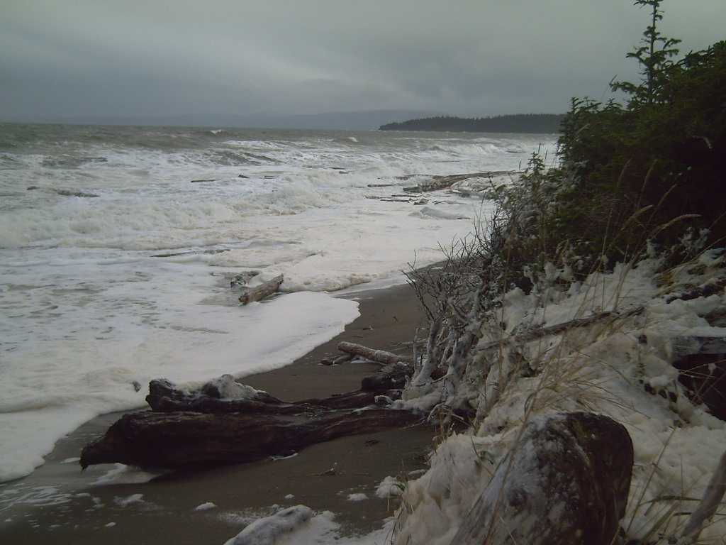
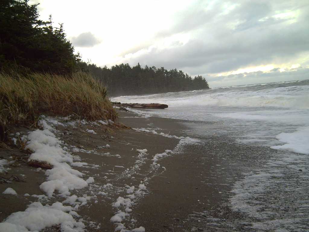
I've shown views of the broad beach below my home at low tide before.
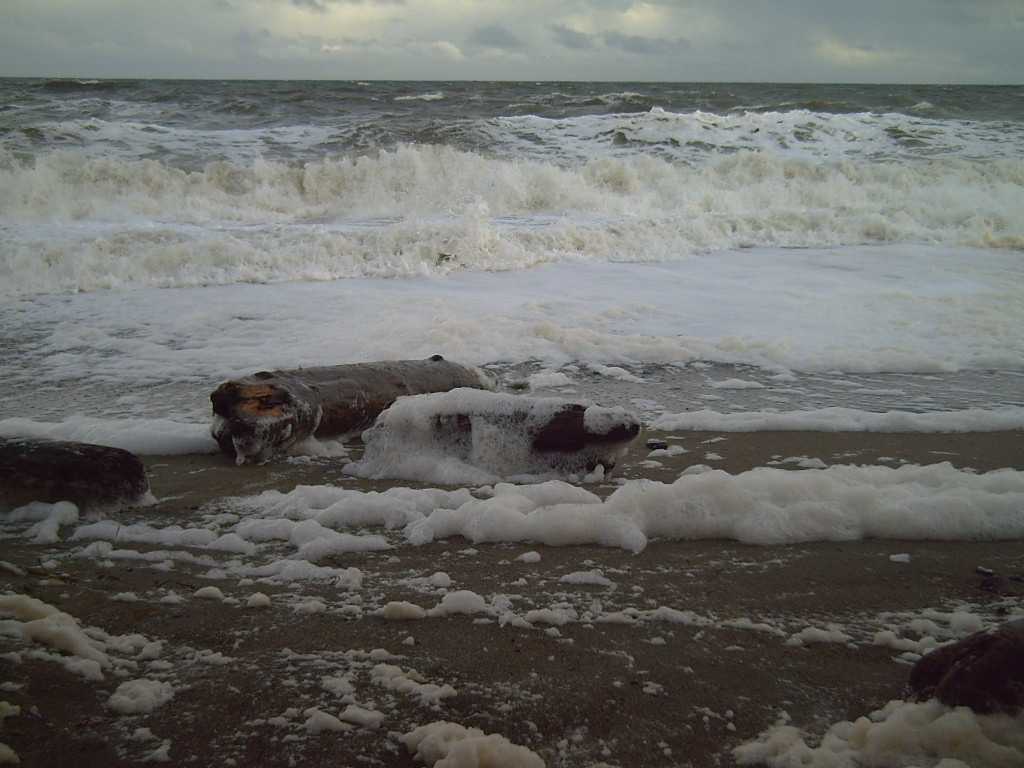
This time I thought I'd try for high tide in a storm with a new moon, November
5th. (Drying foam says I missed highest tide by a 1/2 an hour or so.)
Big logs were rolling and tossing around. Surely there is power in waves!
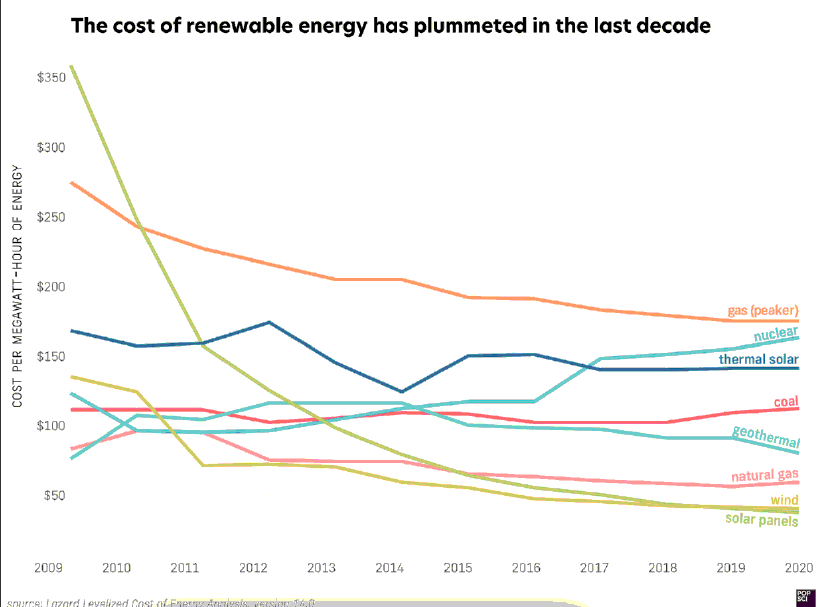
It's nice to know that in all the inflation some things have been getting cheaper:
Solar PV, Wind and maybe Geothermal power.
(When I was a kid in Edmonton, CH4 "natural" gas was dirt cheap. Now it's gassing out of the
former permafrost in the Arctic, but in Europe the winter heating supply is in question.
But it was never "sustainable".)
 Of course I had some ideas of my own tucked away in the back of my
mind too, and I thought again after the power failure of how little
solar power there is here in the winter. So somehow I got sucked into
this new project, unwanted and
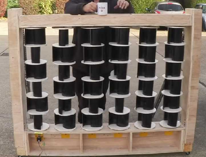
seemingly not very promising in the big picture. I made a tall,
thin Savonius rotor (why a bunch of short ones?) and stood it in front
of my big box fan. Of course it turned, more or less.
Of course I had some ideas of my own tucked away in the back of my
mind too, and I thought again after the power failure of how little
solar power there is here in the winter. So somehow I got sucked into
this new project, unwanted and
seemingly not very promising in the big picture. I made a tall,
thin Savonius rotor (why a bunch of short ones?) and stood it in front
of my big box fan. Of course it turned, more or less.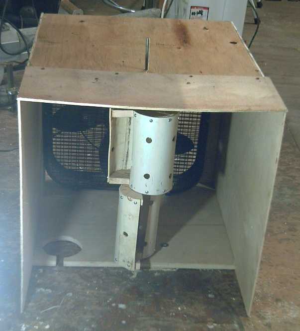 Then I cut it
down to half the height and I made a mini wind tunnel: a box the size
of the fan from
scraps of plywood,
open at both ends. I put a bearing in a hole at the bottom and drilled
a hole for the shaft to stick through at the top. Every rotor tested
would then be mounted in exactly the same place relative to the fan and
tunnel.
Then I cut it
down to half the height and I made a mini wind tunnel: a box the size
of the fan from
scraps of plywood,
open at both ends. I put a bearing in a hole at the bottom and drilled
a hole for the shaft to stick through at the top. Every rotor tested
would then be mounted in exactly the same place relative to the fan and
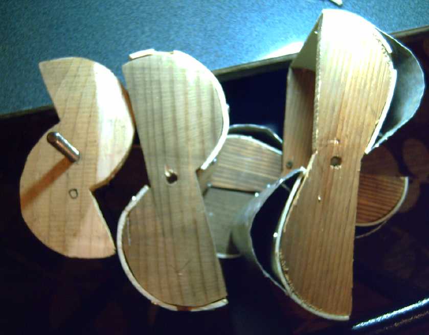
tunnel.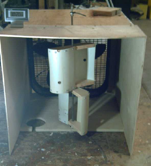 Then I thought
I'd search on line and see if there was anything better. I found a
paper that mentioned a "slightly better" shape and had a diagram of it.
I printed the diagram. "Full page" was just the right size for the
plastic PVC pipe I was using. I heated the pipe in the oven and bent it
to the right shape to fit on the pieces of wood I cut by cutting out
and tracing the drawing. It turned at 82 RPM. But the first rotor was
only 7 inches diameter while the new one was 10 inches, so the same RPM
actually represented considerably more outer rim speed and more power.
Then I thought
I'd search on line and see if there was anything better. I found a
paper that mentioned a "slightly better" shape and had a diagram of it.
I printed the diagram. "Full page" was just the right size for the
plastic PVC pipe I was using. I heated the pipe in the oven and bent it
to the right shape to fit on the pieces of wood I cut by cutting out
and tracing the drawing. It turned at 82 RPM. But the first rotor was
only 7 inches diameter while the new one was 10 inches, so the same RPM
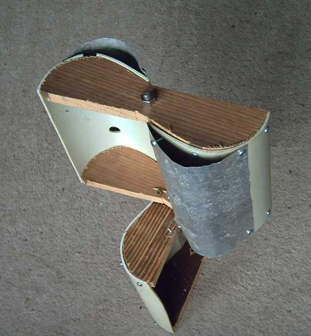
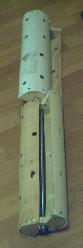
actually represented considerably more outer rim speed and more power.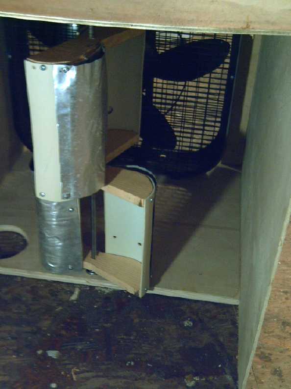 But, I
thought, the new shape was flat both on the back (the main part of the
advantage) and the front - a disadvantage. The front would have more
air resistance returning upwind to the "top" of the power cycle. I
added a second layer (screwed on alium. sheets) that made it a rounded
front face again, which created a further improved "Savonius" rotor
that turned at 90 RPM. That seemed rather thrilling. How much - or was
it how little - creative thought had been given to Savonius rotor
shapes in the last 100 years or so?
But, I
thought, the new shape was flat both on the back (the main part of the
advantage) and the front - a disadvantage. The front would have more
air resistance returning upwind to the "top" of the power cycle. I
added a second layer (screwed on alium. sheets) that made it a rounded
front face again, which created a further improved "Savonius" rotor
that turned at 90 RPM. That seemed rather thrilling. How much - or was
it how little - creative thought had been given to Savonius rotor
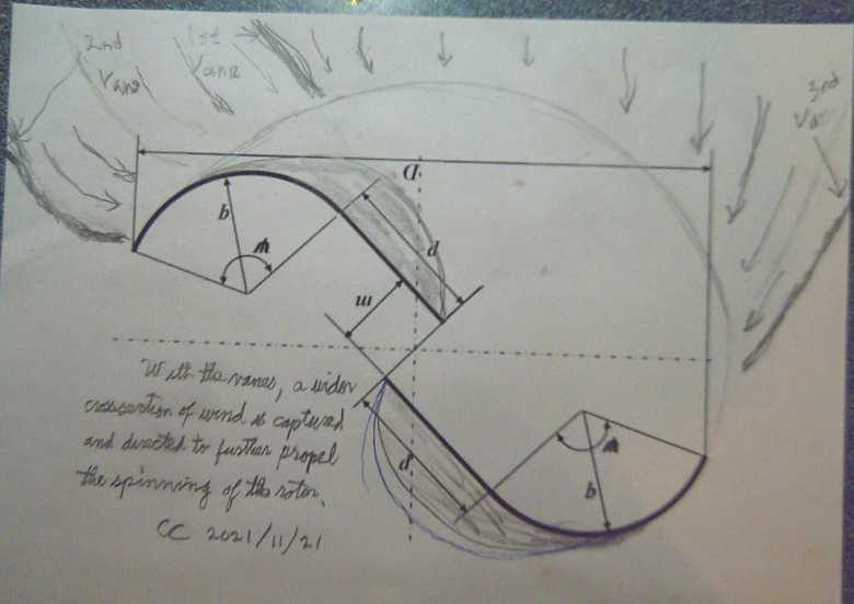
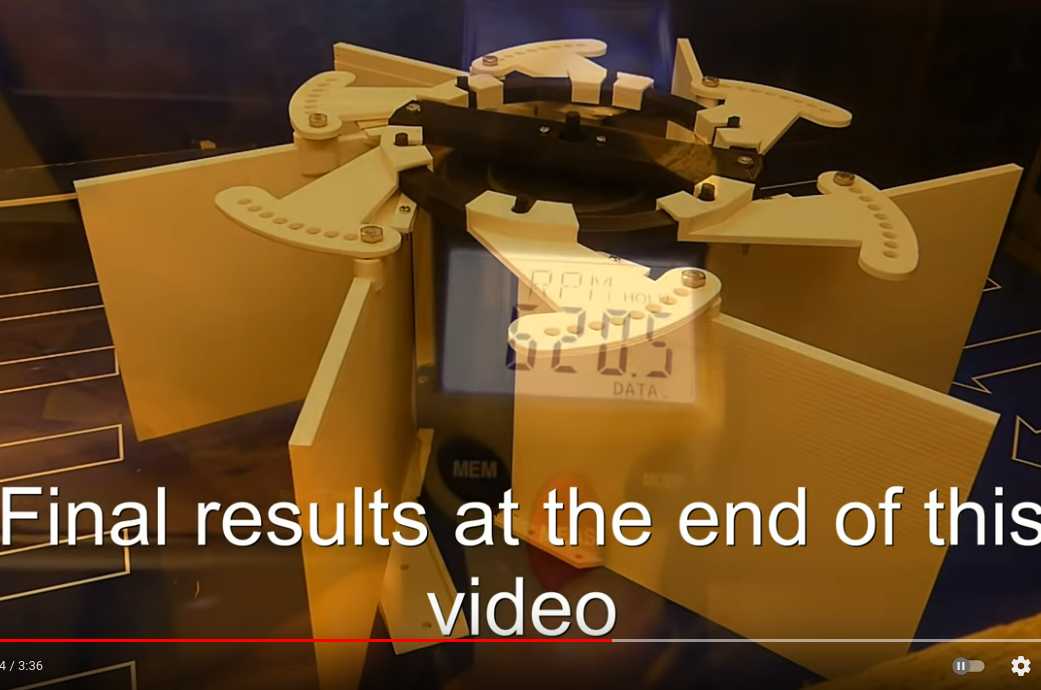
shapes in the last 100 years or so?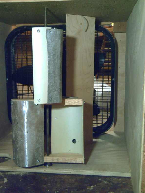 Next I put a
stationary vane in to direct the wind toward the side of the rotor
being pushed downwind, and away from the side pushing its way back
upwind. This also concentrated the wind and increased its speed. This
time the rotor hit 160 RPM, and took some actual bit of force pinching
the shaft to slow it down much. Potential tens of watts, I think. With
a couple of vanes it hit 172 RPM. The vanes would of course be built
into the frame of the wind wall. (Further testing might optimize vane
sizes, placements and shapes, but even one flat board works wonders!)
Next I put a
stationary vane in to direct the wind toward the side of the rotor
being pushed downwind, and away from the side pushing its way back
upwind. This also concentrated the wind and increased its speed. This
time the rotor hit 160 RPM, and took some actual bit of force pinching
the shaft to slow it down much. Potential tens of watts, I think. With
a couple of vanes it hit 172 RPM. The vanes would of course be built
into the frame of the wind wall. (Further testing might optimize vane
sizes, placements and shapes, but even one flat board works wonders!)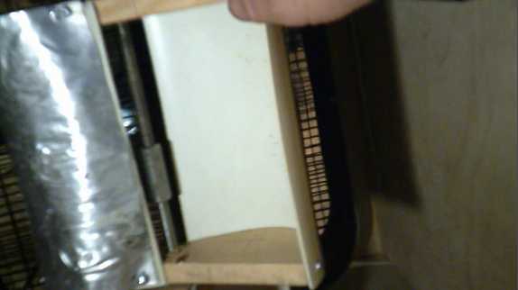
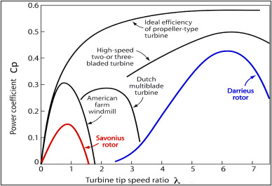
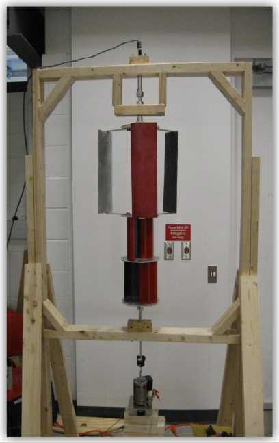 The actual subject of the same
paper was about making and testing a hybrid rotor,
where the Savonius bottom half was the means to start the Darrieus top
half spinning, even in low winds, thus harvesting power with something
toward the efficiency of a Darrieus rotor (~40%) at catching the wind's
energy. (Straight blade Darrieus rotors only work once they are
spinning, so they need some way to start them.)
The actual subject of the same
paper was about making and testing a hybrid rotor,
where the Savonius bottom half was the means to start the Darrieus top
half spinning, even in low winds, thus harvesting power with something
toward the efficiency of a Darrieus rotor (~40%) at catching the wind's
energy. (Straight blade Darrieus rotors only work once they are
spinning, so they need some way to start them.)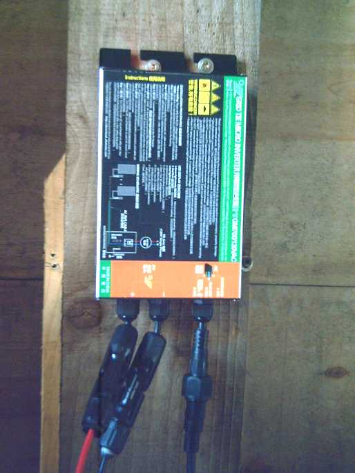 I didn't have
enough grid ties for all the solar panels in summer sun, and I wasn't
happy with the way the present ones kept jumping back to zero and only
gradually ramping up again when a cloud came along. By the time they
were back to full power, another cloud would come and it would start
all over again. So when I ordered 3 new grid ties they were a different
brand, 700 watts rated.
I didn't have
enough grid ties for all the solar panels in summer sun, and I wasn't
happy with the way the present ones kept jumping back to zero and only
gradually ramping up again when a cloud came along. By the time they
were back to full power, another cloud would come and it would start
all over again. So when I ordered 3 new grid ties they were a different
brand, 700 watts rated.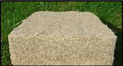 Having looked
up eelgrass, I went farther and looked at
just grass grass. Sure enough, a company is processing that into batts
for insulation, too. The "R" value is around 4.26 per inch, which is
27% better than fiberglass. (~3.3. I never did get an exact figure for
eelgrass - perhaps 3.5?) That would mean R 15 in
a "2 by 4" wall (actually 3.5 inch) and R 23.5 in a "2 by 6" wall (5.5
inch). With such an improvement, might we return to making "2 by 4"
walls as was done up until... hmm, 1980 or so, was it? Around that time
exterior walls started being made of 2 by 6es to get a higher "R" value
than R12 with fiberglass.
Having looked
up eelgrass, I went farther and looked at
just grass grass. Sure enough, a company is processing that into batts
for insulation, too. The "R" value is around 4.26 per inch, which is
27% better than fiberglass. (~3.3. I never did get an exact figure for
eelgrass - perhaps 3.5?) That would mean R 15 in
a "2 by 4" wall (actually 3.5 inch) and R 23.5 in a "2 by 6" wall (5.5
inch). With such an improvement, might we return to making "2 by 4"
walls as was done up until... hmm, 1980 or so, was it? Around that time
exterior walls started being made of 2 by 6es to get a higher "R" value
than R12 with fiberglass.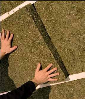 What
processing does it need? Those making it
into batts
were first "de-juicing" it to extract "the cellulose". Their pictures
were pretty tiny, but to me the batts looked
like they were made of bits of straw, so I suspect the process wasn't
very involved and that simply drying it would do almost the same. Then
they added jute and PETE. It was said the PETE could be replaced by
PLA. Starch was also mentioned, and borate. (More info:
www.GrassInsulation.com/technical )
What
processing does it need? Those making it
into batts
were first "de-juicing" it to extract "the cellulose". Their pictures
were pretty tiny, but to me the batts looked
like they were made of bits of straw, so I suspect the process wasn't
very involved and that simply drying it would do almost the same. Then
they added jute and PETE. It was said the PETE could be replaced by
PLA. Starch was also mentioned, and borate. (More info:
www.GrassInsulation.com/technical ) [10th & 11th - Rememberance day! "The
Great War", "WW I", "The War to End All Wars", ended 103 years ago this
month. I'll bet that no one alive today ever met and would remember
anyone who died in that war.]
[10th & 11th - Rememberance day! "The
Great War", "WW I", "The War to End All Wars", ended 103 years ago this
month. I'll bet that no one alive today ever met and would remember
anyone who died in that war.]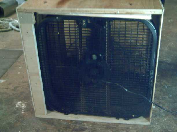 [16th] "In for a penny, in
for a pound..." I went out to the shop (Brr - freezing out!) and made a
plywood box with open ends to blow the fan into. That strengthened the
air flow and made a mini wind tunnel with fairly "linear" air flow to
allow better comparisons of different diameter rotors. I put a hole to
mount a bearing at the bottom and another at the top to stick a shaft
through. That was convenient and also ensured that every rotor would be
in the same place for every test.
[16th] "In for a penny, in
for a pound..." I went out to the shop (Brr - freezing out!) and made a
plywood box with open ends to blow the fan into. That strengthened the
air flow and made a mini wind tunnel with fairly "linear" air flow to
allow better comparisons of different diameter rotors. I put a hole to
mount a bearing at the bottom and another at the top to stick a shaft
through. That was convenient and also ensured that every rotor would be
in the same place for every test.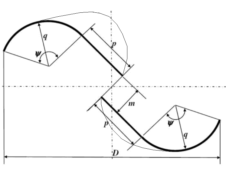 Thus it has the "scoop" profile when the wind is pushing it, and a
"rounded" profile when it's pushing up through the wind to the front
side again. This might even give it better "airplane wing" lift to pull
it forward through some parts of the rotation.
Thus it has the "scoop" profile when the wind is pushing it, and a
"rounded" profile when it's pushing up through the wind to the front
side again. This might even give it better "airplane wing" lift to pull
it forward through some parts of the rotation.