Turquoise Energy News #164
covering
January 2022 (Posted February 6th 2022)
Lawnhill BC Canada - by Craig Carmichael
www.TurquoiseEnergy.com
= www.ElectricCaik.com
= www.ElectricHubcap.com
Special Features:
• Plastic
Recycling 2.0 - remanufacturing/recycling plastics a simpler way!
(Month in Brief, Electricity Generation)
• Water Wall ! the Wind Wall repurposed for
stream, river, tidal power! (Month in Brief, Electricity Generation)
Month
In
"Brief"
(Project Summaries etc.)
- "WindWarp" VAWT Windplant... and waterplant Development &
Research
In
Passing
(Miscellaneous topics, editorial comments & opinionated rants)
- Smol
Thots: Fertilizer & Food Shortages; Trucks Tied Up; Excess Deaths
2021; Land Living Frogs (Permian evolution); A Local Environmental
Collapse? - ESD
- Detailed
Project Reports
-
Electric
Transport - Electric Hubcap Motor Systems [no reports]
* Unipolar Electric Hubcap Motors: Cast PP Bodies?
* Potential Driving Range of the Chevy Sprint EV with the Ultra
Efficient Drivetrain
* Unfairly Maligning the Low Rolling Resistance Tires? - Sticking Brakes
Other "Green"
& Electric Equipment Projects
* CNC Table
* Winter Gardening
Electricity Generation
* Windrap™ VAWT Windplant (& Waterplant) & Plastic Recycling
2.0: - Plastic
Recycling 2.0: General Discussion - Some more casting rotors from PP
ropes - Brushless generators arrive, test - Failure of the "Transparent
PETE Greenhouse Panels" idea - Water Power Plant ! - Casting
Disks
* My Solar Power System:
- Daily/Monthly
Solar Production log et cetera - Monthly Summaries,
Estimates, Notes
For the third month now,
the main project focus has been the "Wind Wall" VAWT windplant with an
outer frame and the new rotor blade shape. Within that has been the new
way of recycling polypropylene plastic for making larger, not very
intricate parts - which after all uses up a lot of the best waste
plastic, potentially making really useful things. Later in the month
there was a big shift in what it was all about and the project assumed
far greater potential for higher and more steady power generation (read
on).
On the 11th it occurred to me to give the type of rotor a
new name. It really wasn't a "Savonius" or a "Darrieus". Rather than
"Carmichael" (which would have been in the tradition), I tentatively
came up with "Windwarp™ ".
 I improved my mold
and was getting
good blades except that too often the outer/back corners weren't quite
filled in.
I improved my mold
and was getting
good blades except that too often the outer/back corners weren't quite
filled in.
I had 15 by the end of the month.
 I did some wind tunnel tests on
the "full size"
rotors with good results.
I did some wind tunnel tests on
the "full size"
rotors with good results.
I screwed the blades in at various angles and distances from center to
see what worked best.
They ended up right where I had first, intuitively, placed them, but
variations in performance at various reasonable positions were not
large.
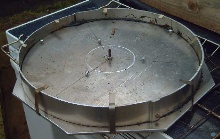 I made a mold to make a top and
bottom circle
for "spool" form rotors.
I made a mold to make a top and
bottom circle
for "spool" form rotors.
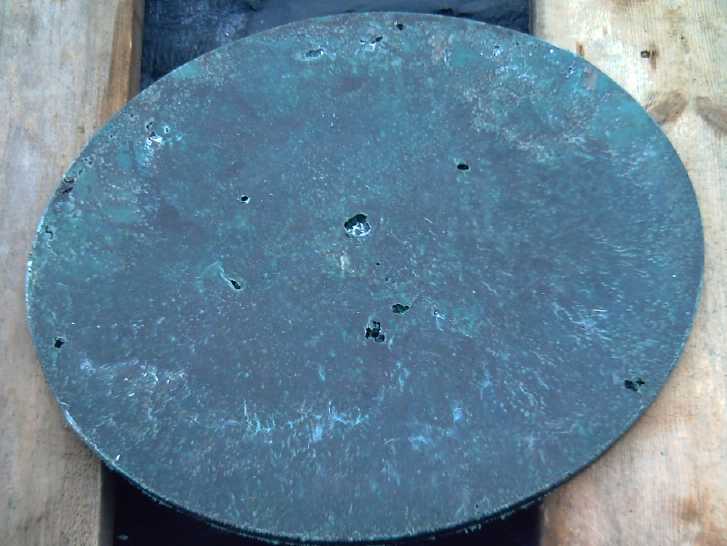 The first circle piece - after 3
tries.
The first circle piece - after 3
tries.
(Why does it take SO long to melt plastic in the hot, hot oven? I
bought a remote laser temperature
sensor and got readings of 262 and 266°C [511°F] on the top of
the mold when I pulled the latest piece out.
In future I can check it and make sure it's up to that to guess whether
the plastic has fully melted yet.)
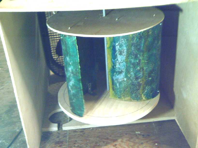
 The real thing - the ROTOR !
(mostly still
needing bolting together).
The real thing - the ROTOR !
(mostly still
needing bolting together).
Water Power Plant !
On the 21st something completely new and different struck
me. But amazingly this time, not something that would have me delving
off onto yet another project! I had off and on since moving here been
thinking about tidal flow power, and possibly of power from shallow,
fast flowing creeks. There's a lot more power, and more consistent
power, in flowing water than in fickle wind. On a trip to Masset as I
passed by Masset Inlet with the tide flow ripping along, it occurred to
me that the "Wind Wall", almost exactly as already designed, seemed in
several fortuitous ways to be a perfect "Water Power Unit" that could
be deployed or installed in many and various ways wherever there was
flowing water.
First, it was a vertical axis with the generator at the
top, right under the roof to keep it driest in the weather. As a
flowing water power unit that would also put it in the air above the
water. One of the most impractical aspects of most tidal power units
I've looked at is that the generator is under the water, in line with
the propeller. Here, vertical axis rocks!
Second, I was already making it out of polypropylene
plastic - impervious to fresh or salt water! If it had a stainless
steel or alium. shaft and a UHMW-PE lower bushing, that would last well
even in salt water, and it would be the only part of concern actually
in the water.
Third, I was already designing it for power in minimal
winds, which is similar speeds to good flowing water.
Then, it's actually better: in a stream the flow is all in
one direction with no need or use for the whole unit to pivot into the
wind, the mounting for which which will likely be tricky for rotors in
a structured enclosure. For tidal flow it's two opposite directions,
and for a fixed aim mounting, a bi-directional "Water Wall" can
probably be as effective as a unidirectional (or close enough).
In addition for the Wind Wall I was going to start with a
"wall" having maybe two shafts of 3 rotor sets each. Water has so much
more power than air that one would gain more power than than wind
provides except in storms, even with a single rotor - maybe even cut
shorter for use in shallow water. And flowing water is guaranteed to
flow most of the time, quite unlike wind except in the most favorable
of locations. Even tides flow much of the time with only short slack
periods gently entered and exited.
Maybe I'll title it the "VAWP" - Vertical Axis Water Plant
24V inverters
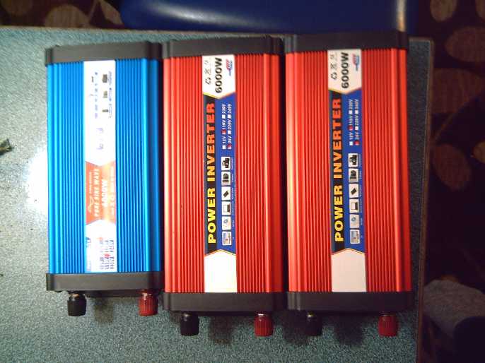 I swear I
ordered two 12 volt DC to 120 volt AC inverters and on spec, one 24
volt DC to 120 volt AC. One was pure sine wave and two were "modified
sine wave", all 3000W, 6000W peak. Somehow all three were 24 volts!
I swear I
ordered two 12 volt DC to 120 volt AC inverters and on spec, one 24
volt DC to 120 volt AC. One was pure sine wave and two were "modified
sine wave", all 3000W, 6000W peak. Somehow all three were 24 volts!
Indignantly I went to the AliExpress site to complain, but
checking my order they all said 24 volts. I still don't know how that
happened.
I used one, with two batteries, to run my angle grinder at
the refuse station. Then I sold one. I guess I should use the money to
order a 12 volt one. (They didn't have 36V.)
In
Passing
(Miscellaneous topics, editorial comments & opinionated rants)
Smol
Thots
* Fertilizer & Food Shortages Nitrogen, potassium and
phosphorus compounds are the fertilizers that are required in great
quantity to provide good crop yields on 'modern' farms. In 2019 some
big phosphate mines closed. According to "Financial Argument" on
youtube, ammonia (nitrogen) fertilizer created using 'natural gas'
(methane) has kept crops flourishing and almost 4 billion people from
starving. That's right: we're that overpopulated that half the world is
in effect at least partly living off consumption of non-renewing
chemicals stored in the Earth for millions of years. (I might also add
that it shows the broken link in our food chain: human excrement is not
recycled to fertilize new crop growth, and is instead considered a
waste product needing "disposal". This is not sustainable at any
population level.) With rising gas prices, major ammonia producers have
shut down and the price for nitrogen fertilizer too is skyrocketing.
Farmers - many of whom have been having a very hard time
in the last few years especially owing to weather calamities and who
have already been bankrupted in the millions - will no longer be able
to afford these manufactured fertilizers. (Where are the lavish
bailouts for our most essential industry?) Corn crop yields will be
hard hit - US corn is output expected to drop by 40% this year. Other
crops' productions will also suffer and soon they'll all be in short
supply if they aren't already. Some want to switch from corn to soy
beans (less fertilizer intensive), but as a result soy bean seeds are
in short supply.
In addition supply chains have been breaking down,
hindering maintenance and repair of farm machinery and trucks for
deliveries. Major ports are now locking out older trucks for
climate/pollution considerations, adding to the bottlenecks.
* Trucks Tied Up And with the ending of the month tens of
thousands of trucks and farm tractors have been in Ottawa, and more in
other places around North America and the world, protesting government
overreach all supposedly related to some virus. How has a medical
concern become a political reason for imposing sweeping dictatorship?
The obstinacy of our prime minister in his refusal to respond to
people's widespread and ever growing concerns about the destruction of
freedom, the economy and society in general is surely contributing to
empty store shelves for the duration which doubtless will last weeks or
months beyond. The outlook for 2022 and beyond for crop production and
distribution to grocery stores is rather bleak - especially in the
absence of caring and competent leaders in our positions of power.
Where are the big bailouts for the destitute farming community?
Ensuring our food supply is more important than bailing out the banks
was in 2008.
* Excess Deaths 2021 According to Greg Hunter (USA Watchdog -
1st program of 2022), who got it from Robert Malone (perhaps the
leading mRNA vaccine researcher), who got it from new life insurance
actuarial tables, deaths from all causes of working age people 18 to 64
were up by 40% in later 2021. Apparently it is still rising.
In another video Scott Davison, CEO of One America Life
Insurance company, says a 10% rise in this number would indicate some
huge "once in 200 years" disaster had occurred. It was up by 20% in the
second quarter. The 40% in the third and fourth quarters of 2021
(ending in October) is "off the charts". In addition claims on short
and long term disability insurance are way up. He says these figures
are consistent across the industry and that most of the excess deaths
weren't attributed to Covid. Some of the timeline was before the mild
"omicron variant" appeared, and mostly it's the elderly who die of
Covid. What was so different in 2021 from all previous years? Please
draw your own conclusions.
* Land Living Frogs When some time ago (TE News #100, #112,
#141) I wrote about the unlikelihood that there were any reptiles until
well into the Triassic period and still less in in the Permian or
prior, the biggest question mark in my mind was that if the Listrosaurs
(or more generally genus Lystrosauridae as there were several species)
were a sort of "pre-reptilian frog" or "toad" (and my take from the
skeletal features, having advanced costal (diaphragm) breathing instead
of primitive buccal "frog" breathing), so different from other and
previous Carboniferous and Permian period amphibians, and seemed to be
a land dweller, how did they reproduce? No egg shells have been found
until after the first perhaps 10 million years of the Triassic. A land
dwelling creature couldn't have laid soft eggs in water and had
tadpoles. I was left to suspect that they must have borne live young,
but as far as I knew there was nothing similar to compare it with.
But this month I learned of some "ovoviviparous" genera of
toads, Nectophrynoides and Nimbaphrynoides, that give birth to live
young - little "froglets", rather than laying eggs in water that become
tadpoles. So! There is an extant "precedent" (can that be the right
word?) for what I have been assuming (in the absence of other options)
probably must have been the Lystrosaur's mode of reproduction: land
living frog family creatures that bore live young.
* A Local Environmental Collapse? I watched a documentary of an
anthropological dig in Cornwall (Youtube), The Buried Bronze Age
Ruins of Bodmin Moor | Time Team | Odyssey, presented by Tony
Robinson. (Apparently just one of a Time Team archeological TV
series.) Cornwall is the southwest corner peninsula of Great Britain.
There are many farms and towns, but the moor and its promontory Rough
Tor (somehow pronounced "Roe Tor") is a desolate, wind swept area with
more rocks than soil. There were stone footing walls and burial relics
of neolithic and bronze age peoples. Why had people chosen to live in
such a forbidding place, where no one lives now?
As the video went on, they analyzed pollen in ancient soil
underneath stones laid down way back in the bronze age, if not in
neolithic times. They concluded that the area had been an oak and hazel
forest. As usual with prospering human civilizations, forest got cut
down for firewood and to clear land for grazing animals, then for
farming. Until, as usual, after enough generations of degradation there
was no forest left and the wind and rains swept through, possibly
blowing or eroding away the forest soil. Then acidification of the soil
prevented the forest from growing back. However, there are farms all
around Cornwall (Google maps) so the area so ruined way back then
seemed to be limited to the area of the hillsides and higher grounds
around the Tor where winds were strongest and regrowth slowest. So
maybe in this case it was more a limited local environmental collapse
than a societal or civilizational one.
But again, if only locally, we are left with the saying
"Civilization starts with a forest and ends with a desert."
ESD
(Eccentric Silliness Department)
* "Foreign businesses are leaving China in droves." What is a
drove? I haven't heard of these before. Can a drove
hold an entire business? Factory equipment, offices and all? Is it
bigger than a bus? Or maybe it's some odd plural form of "drove"? In
that case, they may have all droven off in private vehicles, en
masse.
* I couldn't find the metric equivalent of a "drove" anywhere. How many
droves in a liter? or kilometers in a drove? Looking for
it drove me nuts.
* In a dictionary I actually found that a "drove" refers to having
driven a herd of cattle, so "in droves" alludes to moving large groups
or "herds". (Well, duh!)
* The old adage says: "Don't take any wooden nickels!" Wow, a carved
wooden nickel would be an amazing work of art! I'd give anybody 20$ for
a well made wooden nickel!
* What is the difference between a caregiver and a caretaker?
"in depth reports" for
each project are below. I hope they may be useful to anyone who wants
to get into a similar project, to glean ideas for how something
might be done, as well as things that might have been tried, or just
thought
of and not tried... and even of how not to do something - why
it didn't
work or proved impractical. Sometimes they set out inventive thoughts
almost as they occur - and are the actual organization and elaboration
in writing of those thoughts. They are thus partly a diary and are not
extensively proof-read for literary perfection, consistency,
completeness and elimination of duplications before
publication. I hope they may add to the body of wisdom for other
researchers and developers to help them find more productive paths and
avoid potential pitfalls and dead ends.
Unipolar
Electric
Hubcap
Motors:
Cast PP Bodies?
About mid month it occurred
to me,
now that I was melting and molding parts for the windplant, that I
could also do the same for motor body parts! Instead of making UHMW
molds and casting polypropylene cloth-epoxy with the set epoxy making
it
hard, I could make alium. molds and simply cast pure [recycled] PP
parts in the oven. I've had electric lawnmowers with bodies made of
solid PP.
It's tough stuff, and I could make it quite thick without adding much
percentage weight to the copper and iron of a motor. (After all, it
floats!) And seeing how
much heat it takes to melt it, perhaps pure PP could run a little
warmer than PP-epoxy?
Well, I may not be getting it built in all this time, but
the design details
keep improving. The CNC table is finally
working and the HHO torch for cutting metal with it looks doable. It's
looking like when and if I get to them, the building should go
smoothly and they'll be great motors. (I hope the 330mm [13.0"] magnet
rotors aren't too big to manage when mounted on solid trailer stub
axles, and that the 6 phase unipolar
motor controllers they'll need won't be too difficult to create!)
Potential
Driving
Range
of the Chevy Sprint with the Ultra Efficient Drivetrain
Since I got the Sprint
running last summer with the highly efficient drivetrain (motor to 96%
efficient planetary gear straight to right wheel CV shaft), I have idly
wondered what its potential range might be on paved road and (more
especially) whether it could potentially be driven to town and back.
Since it didn't go fast enough to actually drive on the highway in
traffic - and almost surely wouldn't make it back up my steep driveway
because of its low torque with only the 5 to 1 reduction ratio - I
didn't dare try it out.
Now it occurred to me that I have enough info to calculate
at least theoretical potential ranges.
* I know the theoretical capacity of the battery: 240 amp-hours (at 36
volts nominal - about 9 KWH).
* I know the distance to town: about 27.5 Km.
* I know vaguely how much current the car drew driving at a constant
speed on the bumpy lawn where it was some approximation of level: In
the June 2021 trials in TE News #157 I said "30 to 70 amps" and later
"30 to 50 amps". (In spring 2018 I had noted around 70 amps average on
the highway in short tests. The speeds were even lower, but the
transmission would have been less efficient.)
* I know the rough speed range from trials after getting the bicycle
speedometer for it in July (TE News 158). On the bumpy lawn over the
short run it could accelerate, it never got much over 25 Km/Hr. But I
estimated it should pick up speed to average 35 to 40 Km/Hr on level
pavement. My earlier hopes of 45 were probably overly optimistic. (Even
40 might need a bit of down slope. The 55 it got up to free-spinning
the tire jacked up would only be going downhill.)
Let's take what would likely be the worst case for driving
to town and back:
27.5 Km * 2 = 55.0 Km
55 Km / 35 Km/hr = 1.57 hours of driving
70 amps * 1.57 hours = 110.0 amp-hours
Wow! That says it should make it to town and back even if I took out
one of the two battery stacks and had only 120 amp-hours!
110 amp-hours * 36 volts = 3960 WH of Energy consumed. (The Nissan Leaf
uses double that [in summer] or more.)
That's worst case. Now let's assume things are more
favorable (probably closer to a "best case" than a "medium" one.):
55Km / 40 Km/Hr = 1.375 hours of driving
50 amps * 1.375 hours = 69 amp-hours.
69 amp-hours * 37 volts = 2544 WH
So with the 240 amp-hours, the minimum (pessimistic)
potential range would be 120 Km. In the more favorable scenario it
would be 190 Km to "dead batteries". The farthest town on the island,
Masset, is 170 Km round trip from my place. (The scenic north coast is
a little farther.) Getting there and back with just 9 KWH of battery
would be amazing. The Nissan Leaf can't do the round trip with 24 KWH.
Well, theoretical is fine. The real proof would be in the driving. But
of course even if it was safe on the highway, it would be frustrating
to drive so long so slowly. One might fall asleep at the wheel!
I was wishing I knew the actual RPM rating of the present
motor under load. But let's see... another simple calculation: With
10.0 wheel RPM for each 1 Km/Hr, and 5 to 1 reduction from the motor,
at 35 Km/Hr the motor would be turning 1750 RPM, and at 40, 2000 RPM.
At the top speed the car got to on the lawn of 25 Km/Hr, it would only
have been doing 1250 RPM. With the free-spinning jacked up wheel in the
garage it hit "54 Km/Hr" or 2700 RPM. It seems to very much depend on
the load.
If I ever get that new unipolar BLDC "Electric Hubcap"
motor made (probably safe max ~3500 RPM limited in the controller
instead of 1750~2200) the Sprint should probably get up to maybe 60-70
Km/Hr. Still not fast, but I would license it and try it out. It might
not be much different in power consumption: an ultra-efficient motor
replacing a rather inefficient series wound motor... but the car would
be driving considerably faster and get to town in pretty fair time.
Then again, if I took out one of the two battery stacks
(to have two for the 72 volt Miles mini-cargo truck), seemingly I could
make it to town and back with either vehicle. (I keep assuming I can
reprogram the Miles to go about 60 Km/Hr. I suspect a broken or cut
connection from the motor controller to the programmer is what kept me
from doing so earlier, and I didn't look at it last summer or since.)
Unfairly
Maligning
the
Low Rolling Resistance Tires? - Sticking Brakes
I discovered this month
that the rear brakes were sticking on the Nissan Leaf. With the gravel
and salt on the highway in freezing winter weather, they started making
a considerable grinding noise, at first when I used the brakes, but
then it seemed to be more and more, and the energy economy got worse.
(I then remembered it helps to wildly jerk the car from side to side to
flex the assemblies to retract the brake pads & pistons from the
disks a bit.)
Did this perhaps begin last fall and only lately get
noticeable? Now I'm not sure whether or how much of the poorer economy
I've been having has been due to the brake pads rubbing on the disks
and not to the Bridgestone Ecopia "low rolling resistance"
tires. Are the tires actually not even part of the problem?
I finally took a wheel off and looked. The brake rotor
disk was shockingly worn considering how rarely one uses the brakes
driving the highways around here. There are few crossroads and no
traffic lights, and one mostly uses just the 'gas' pedal until arriving
at one's destination. (except when encountering kamikaze birds that sit
on the highway until the last instant and then fly up in front of the
car, and of course insolent deer and the very occasional bear.) Of
course, I did buy the car used, so maybe they were already considerably
worn. I didn't notice when I had a rear wheel off before.
I've bought new rotors. I'm not sure whether to put them
on now or wait until maybe March and hope that's the end of
graveling/salting the roads until next fall. After they're on we may
see whether the energy efficiency markedly improves.
Other "Green" & Electric Equipment Projects
CNC Table
[8th] The "PCI Express" parallel port
arrived. It fit in the computer! I screwed it in and found a parallel
to parallel cable. Linux CNC started up instead of exiting with a "no
parallel port found"
error message. I went to "manual control", selected "X" and hit "+".
It
moved!
"X" and "Y" moved the carriage across the table. "Z" would
only
go down. Somehow there wasn't enough torque for it to lift the router
and its mountings up. But I was well satisfied. The machine plus the
computer interface was, at long last,
working!
YAY!
[9th] If I lifted a bit on the router, "Z" would go up. Once it was up
a bit, it continued by itself. It only "stuck" down when it was down
very near the bottom - probably lower than it would be with any bit or
tool in its chuck. I tried stopping the "X" and "Y" motors from moving,
but they seemed to have a fair bit of torque. (Not that I couldn't
stop them.)
Then I went into the "step configuration" program and
found how fast the motors could reliably drive each axis. Not very
fast, and "X" was slower than "Y".
It seemed good enough to try out. What was I going
to try making? Without the HHO torch working, metal was out. (Yes, I
bought a plasma cutter a while back. But I suspect the HHO torch will
prove much
superior and make cleaner cuts.) I didn't want to hack up valuable
plastic, or to attempt routing alium, so that left plywood. Am I going
to do it in the house and get sawdust everywhere, or take it all out
through the pouring rain to the unheated shop? And set it up where?
First I had to design something, and then convert it to
G-code. In OpenSCAD I designed a test hub with 3 spokes to try out the
PP windplant rotors at different angles and distances from the axle.
In the evening I managed to send a few G-Code commands
from the computer and have the motors move, and I got it to run the
default test program. I was however unsuccessful trying to get
"DXFToGCode" to run properly on my desk computer. It would start, but
hang or crash whenever I tried to load a DXF file. So I am so far
unable to get the shapes I've designed to LinuxCNC to run the machine.
Am I going to have to write direct G-Code to make this work? Well, I
did it that way before. What are my other options?
Winter
Gardening:
¡
Sterilize
the
potting soil !
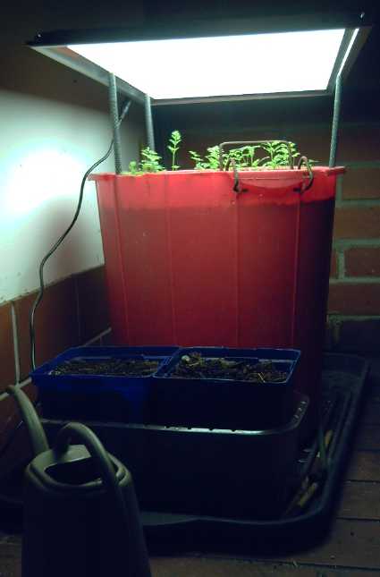 Sometime around the start
of December I planted carrots in a big deep bucket. I set it near the
woodstove with a one foot square LED grow light propped up on "stilts"
over it. In a week or more they were sprouting... and soon after
falling over, losing their leaves and wilting.
Sometime around the start
of December I planted carrots in a big deep bucket. I set it near the
woodstove with a one foot square LED grow light propped up on "stilts"
over it. In a week or more they were sprouting... and soon after
falling over, losing their leaves and wilting.
I've had bad results with carrots before, but these were
indoors and getting lots of water. Could there be something in the
garden soil I had used, eating the tender sprouts? I thought back to 50
years ago when my dad had once been putting soil in the oven to
sterilize it. I looked it up on youtube. Fungus gnats! They're
everywhere. That's why you sterilize soil before planting seedlings in
it. Duh! How long have I been gardening or trying to garden, and often
not knowing why I was having problems? More often I bought potting soil
in bags - pre-sterilized! It must be whenever I didn't that I had
problems.
I saved my remaining carrots with insecticidal soap, and
again a week later. Later I watered with about .75% hydrogen peroxide.
It's supposed to kill the larvae in the soil. That doubtless helped too.
At first they were growing taller and spindly, and I
lowered the light panel. Then at the start of January I traded the red
and blue LEDs 'grow light' for a 4000K light panel on the 36V DC power
system. (With a 10 ohm resistor this one had a whopping 12 watts over 2
square feet, instead of 28 watts in
half that.) By early January the carrots weren't very tall. Maybe they
just stopped bolting for light because they were getting enough? and
instead growing their roots? If so, in spite of it being just 3 inches
above the leaves,
that's pretty impressive for so few watts.
I had also planted lettuce and spinach in my usual long
narrow
pot. In spite of the soap, mostly the fungus gnats must have cut them
down, then I neglected to water for a day (was it two?) and the last
lettuce seedling
wilted.
Since the new light was wider than the carrot pot, I tried
lettuce again at the start of January, filling two smaller square pots
with a
mix of dirt -- this time all sterilized in the oven. Two broke the dirt
on the 8th and several by the 10th.
But they seemed to be getting too long and spindly, so I
went back to the 40W grow lights. By early February the carrots were
growing well and looking like they would be a good crop.
But soon I gave the lettuce too much nitrogen, too
concentrated. They wilted and I had to start over again.
Electricity
Storage
(Batteries)
[No Reports]
Electricity
Generation
Wind Wall ...& Plastic Recycling 2.0
...& VAWP: Vertical Axis Water Plant
Plastic Recycling 2.0: General
Discussion
I'm calling my
plastic recycling method "Plastic Recycling 2.0" to differentiate it
from "typical" plastic recycling methods. In "Plastic Recycling
1.0" techniques for example at PreciousPlastic.com , one first shreds
the
original plastic items to break them down into bits that can be heated
in
an injector or extruder.
Having to shred the source material greatly complicates
the entire process, even if it's light food containers. But what about
old PP ropes? fishnets? 200 liter plastic drums? Fishing floats? Tote
boxes? Other big plastic items? Without at all disparaging the
recycling of the continuous barrage of food containers and other small
packages, larger, heavier items contain much more plastic material than
small, light items, and "1.0" with a typical plastic grinder has no
ready means for dealing with them.
"2.0" can deal with all of them, and more easily.
Everything is simpler. To recap:
Advantages of "2.0"
1. The range of plastics that can be easily employed is greatly
extended, and there is much less processing of the raw material.
Imagine trying to shred a 2 inch polypropylene rope? The regular
plastic package shredding machine surely won't manage it. Here the rope
is only cut roughly into lengths that will fit into the mold. (A zip
disk makes
short work of cutting thick PP rope. Pull on the rope while
cutting.) How about fishnet? surely
it would jam the shredder. Cut it to the right weight of material and
fold or scrunch it into the mold. There are thousands of pounds of
fishnets cleaned off of beaches sitting at a property just down the
road.
Bulky packages and bottles can either be cut into chunks
or thrown into the oven in a box to collapse them.
2. In general, the plastic for forming larger objects doesn't have to
be totally clean. If there are grains of sand or small bits of organic
matter still embedded after it is rinsed, as long as the end product is
not to be used for food or a waterproof container, it's doubtless good
enough. This is a big advantage in reusing material salvaged from the
environment.
3. The equipment required is lower cost, lighter weight, non-precision,
and uses just one special item: an oven. (A scrap kitchen oven will do
for many molds, or a longer, wider one may need to be created for large
"boards", "posts" and sheets.)
4. The molds, having to contend only with tens of pounds of weights on
top rather than with the high pressures of injection or extrusion
molding, can be much easier to make. Sheet or plate alium. can be used
to cover
large, flat areas, perhaps with stronger pieces such as bars, plates or
"angle
iron" (all alium.) reinforcing. They can be bolted (or even
spring-clipped) together, and
un-bolted if required to remove the part. (Note that steel expands less
than alium as it heats. This can warp the alium. so it is recommended
that all the larger/longer mold parts be alium. or use springs) Plastic
shrinks more than
alium. as it cools and also doesn't adhere to it, so it's generally
easy to get the part out of the mold. (It may be advantageous to spray
the mold with, eg, silicone lube.)
Disadvantages of "2.0"
Never much of a salesman, here also are the weaknesses I
can see in the "2.0" system.
1. It is for larger parts, not fine detailed ones. Forget keyboard keys
and plastic feet for electronics! Think boards, posts, beams, big
sheets, tiles, "giant lego blocks", "cutting boards", plates...
and of course windplant blades, rotor pieces and enclosure parts!
2. The parts produced will in general be less precise than injection
molded parts. This does depend considerably on the skill and attention
to detail of the mold maker.
3. Ability to mix colored plastics to get cool patterns is more limited.
4. It is not always appropriate for making complex part shapes. (Forget
making PP electric lawnmower bodies?)
Equipment:
1. The only special piece of equipment, used for everything, is an oven
large enough to hold the biggest mold for the biggest pieces it is
desired to make: No shredder, no injector, no extruder, no large sheet
press. The oven should be capable of reaching somewhere around
260°C (500°F). For health and safety this oven should ideally
be located outdoors and sufficiently far away from flammable structures
when in use. But it is the plastic melting heater for all molding and
it has to plug in, usually to 220V. A larger oven may need two or even
more "regular oven" heating elements.
A regular kitchen stove with oven may be serviceable for
smaller parts. I note however that I connected the plug straight to the
oven element on mine so with no temperature control it surely gets
hotter than most, and that the inner glass has cracked in several
places, probably from the heat.
2. A simple alium. box mold with a fitted lid for each and every
desired part. No matter how you are going to form plastic into new
things, each unique part will need a unique mold. Simple box molds can
be made with sheets and various thicker pieces of alium. instead of
welded steel or milled parts of heavy alium. They don't have to take as
much pressure as molds for injection or extrusion and so don't need to
be as strongly built. They do have to take the heat of the oven, so
(eg) wooden pieces are "out".
3. A temperature control is desirable, but simply timing the melt can
also be serviceable. (I found a "laser thermometer" at the end of the
month: point it at the object whose temperature is to be measured and
press the trigger. I'm sure it will be valuable.)
Procedure:
Note: In the windplant making section below are examples of the
components of making molds and parts.
1. The mold is filled with chunks of the desired plastic to the desired
weight or the amount of weight that will fill the mold.
2. Heavy (steel - lead might melt?) weights are distributed on the lid
of the box. (These replace the high pressure needed for injecting or
extruding.) Typically it seems 25-40 pounds are required for "kitchen
oven size" molds. (Support the oven rack.)
The lid will not fit into place on the box with all the lumps of
plastic in it. The sides of the box must be tall enough or otherwise
arranged so that as the plastic melts, the lid will end up in its final
position as it lowers.
3. The oven is plugged in or turned on and left on for the amount of
time required to melt the plastic and have the mold's lid drop down to
its final position to correctly shape the part. This depends on the
type of plastic, how fast the oven heats, and how long the pieces of
plastic take to heat up and melt down, so no hard and fast rules can be
made.
4. When the time is up, the oven is turned off and the door opened. The
mold and part are left to cool for the desired length of time until the
plastic is solid again and the mold is considered safe to handle. If
there are screws going through the part and setting the
depth/thickness, they should be unscrewed before it cools too much, as
the plastic shrinks a bit and will probably crack around or between the
screws.
5. The mold is opened and the part removed.
In the early trials, if the plastic hasn't completely melted, the
process is tried again for a longer time. If it has and perhaps seems
"overdone", a shorter time time may be tried for the next similar piece.
Now back to the windplant development.
I'm not sure why these pictures didn't make the December
newsletter, tho the tests were near the end of that month. There I
wrote of trying out a single blade in the wind tunnel to see where it
had positive and negative turning force. It was largely positive:
stronger forces over a broader angle of rotation than the counter
forces as the blade returned upwind.
 "Top dead center" where
resistance is turning to positive rotational force
"Top dead center" where
resistance is turning to positive rotational force
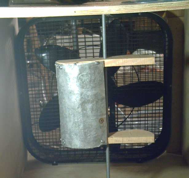 Midway down the power
stroke, which doesn't end until well past "bottom dead center"
Midway down the power
stroke, which doesn't end until well past "bottom dead center"
Last month I wrote about this: "[It] had positive force, measuring from
the axle to the outside edge of the blade, from about 350° (just
before it reached the fan end) to about 230° (well past where it
pointed straight away from the fan). Thus it was providing thrust for
2/3 of the circle and resistance for only 1/3.
Moreover, subtracting the areas where there wasn't much
force either way, the thrust was reasonably strong from about 45 to
190°, a 145° range. As the blades are 120° apart, one blade
will always be in the strong thrust area. The resistance was strong
from about 270 to 330°, a 60° range. So the region of good
thrust was over twice as large as the region where it was really
resisting." and "the forward force around the maximum area felt
substantially stronger than the resistive force around its strongest
area."
It was a good thing to test and it showed how the rotor
shape works quite well.
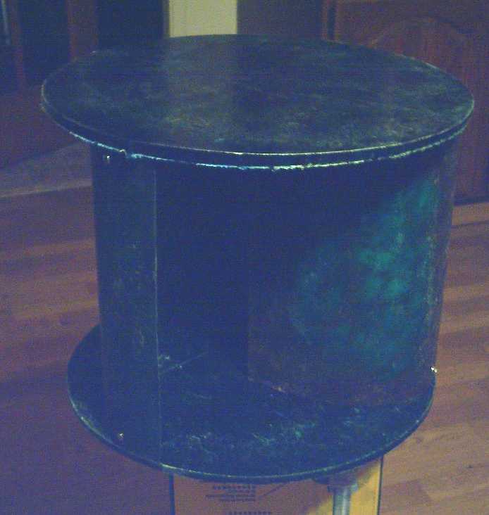
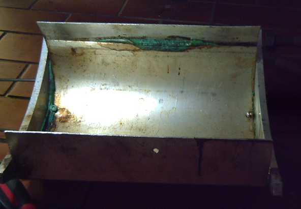
[5th] I went to the refuse
station looking for weights and instead found a big steel "box" to use
for the inner shell of a long,
wide, low oven. It didn't look quite as big as I had wanted, but it
seemed about right otherwise. It looked like it could save me a whole
bunch of work making my own. It had two hinged doors or lids on top.
(The tail of the car already having a 45 gallon drum of planer shavings
from a woodworker in it for the chickens, I put it across the
folded-down back seat
and drove home with the rear right door open. Funny there seemed to be
a lot more road noise than usual from the snowy, gravelly highway. and
it didn't
make the car any warmer. At least with the electric car there was no
chance of exhaust gas coming in.)
The box measured about 19" * 58" * 10" (inside) - not
quite the 2 feet wide and 5 feet long I had hoped for. Oh well! It had
a "step" in the length and was shorter, 52", for the bottom 5-1/2". It
looked sufficient for a couple of oven elements and tall enough for the
windplant blade mold. It was probably sufficient for making all the
parts for
the wind wall if I didn't get too carried away as to size. Wind Wall
1.0, anyway!
My idea for greenhouse wall panes from transparent PETE
will have to be shrunk to about 16 or 17 inches by 56 inches (4' 8")
max. Likewise, beams or boards longer than 4' 8" will likely be
problematic.
It would be nicer to have "boards" and greenhouse wall
panes long enough to
provide standing height. Is there any way to expand it a foot plus, to
at least 6 feet? As it is -3° and everything including the box is
covered with snow, I'll have to check the feasibility later.
---
Take 10
Then, after yet another blade came out with the right hand
side not pressed fully down to the screw, in spite of having over 30
pounds of
weight on it, I started to think that something was probably flexing
and the right-rear side of the bottom was sagging down.
The angle pieces I had used for the sides rested on two
narrow "foot" sections, rather casually cut out of the corners with the
bandsaw. I moved the two side pieces together, sliding the left one in
along the spacing rods. Aha! one had a slightly different slope than
the other. It wasn't much, but it was in the direction that might
explain it. I suspected the more weight I put on top, the harder it
would
push it out of line!
With the rods tying the pieces together, I took them out
to
the shop and ground and sanded them together to make them even. When
assembled it
seemed more solidly seated, where it had rocked back and forth before.
[6th] Take 11, 12 It didn't seem to help. Maybe what it needed
was for the weight to be more in the middle instead of some distributed
up the back as far as possible? Maybe because of the weight there the
back wouldn't flex as it needed to to sink into place? I tried again
with about 28 pounds thus positioned. None was preventing the back
portion of the "lid" piece from flexing forward. That was easier to set
up, too.
No dice. In fact, neither side went down home, and the
plastic didn't reach the left and right sides, much less the corners.
What to do next? Could all that weight really not be enough? I
hadn't been able to find more steel for weights in the snow at the
dump. Suddenly I remembered; I did have one more good weight: my
makeshift anvil was 16 pounds. That made 44 pounds. I put the same
plastic (had been ropes, now a solid blob) in the oven again for
another hour.
This time it was fully pressed down, and most of it looked
great. It really did need all that weight to work well!
At the back at the top, however, with no weights pressing against the
back, it had bulged open. Plastic had pushed out the middle instead of
filling the corners. The melted plastic must exert a very strong force
trying to form a blob instead of flowing out to fill the long, wide and
thin mold! But again, the windplant blades are the most difficult part
I want to make, and the amount of equipment this simple oven-molding
technique replaces makes it worth pursuing to the ultimate.
It seemed what it needed next was a cross support near the
back-top to stop the outside from bending back, and the cylinder
weights pressing against the back from the inside - in addition to all
those other weights pushing down. Then I thought I would start getting
the blade shape I had designed into the mold!
[7th] Take 13 Well, I tried redistributing the weights. Even
with 40 pounds, it didn't press down, not even half way! It looked like
maybe the lid had hung up on the top of the bottom at the back. So much
for pressing against the back as well as down! I couldn't seem to press
it down with a stick, either.
While waiting for it to cool down, I started thinking the
2mm / 12 gauge sheet alium. simply wasn't quite stiff enough. Not when
so much weight was needed. My idea of cheap, light box molds might need
a little revision. Thicker alium. like 10 gauge might make the
difference. But I started thinking instead, maybe thick alium. ribs
below the bottom sheet and above the top, cut to the exact curves, to
ensure they hold their exact desired shape might make the difference.
Once again this comes down to having the CNC table working
and cutting alium. (And finding some thick alium. to cut.) Maybe I
should give up on trying to make blades until I have the CNC table and
the HHO torch cutter working? Ug! Perhaps in answer to my (?)prayers,
the parallel port I had ordered had arrived at the post office.
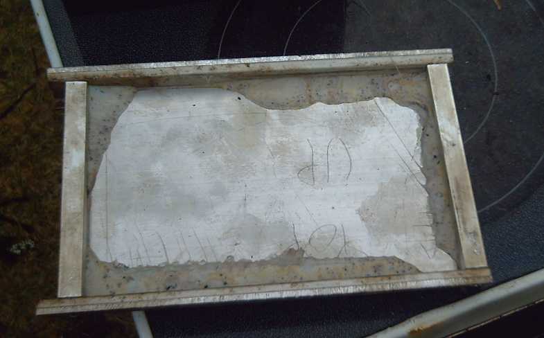
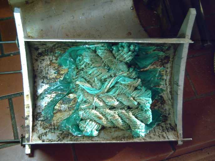 When the mold
had cooled I opened it and found it was a
totally different problem. After an hour in the oven, the PP ropes had
only partly melted! They had shrunk to half their length, but still
looked like ropes. This could mean one of two things: either the oven
element was cutting out or, more likely, the door hadn't been quite
shut. I had noticed it not quite shut before, the door sticking out
just a 1/2 inch or an inch at the top. Sure enough, an hour with two
boards propped against the door melted it. It was still missing those
two back corners. Time for a modified plan!
When the mold
had cooled I opened it and found it was a
totally different problem. After an hour in the oven, the PP ropes had
only partly melted! They had shrunk to half their length, but still
looked like ropes. This could mean one of two things: either the oven
element was cutting out or, more likely, the door hadn't been quite
shut. I had noticed it not quite shut before, the door sticking out
just a 1/2 inch or an inch at the top. Sure enough, an hour with two
boards propped against the door melted it. It was still missing those
two back corners. Time for a modified plan!
[8th] I showed the blades to Steve. He had the idea to make mountings
for them that would let each blade move in and out from center as well
as swivel. "U" tracks or something? Thus some rapid experimentation
could narrow down the best angle and distance from center of the blades
on the rotor. That sounded worth making to me. Steve, who has plastic
molding experience, also said that having all the plastic at the same
temperature (because it was all in the oven at the same time) was
valuable - presumably over plastic that is cooling as it is being
pumped into a mold under high pressure.
The next day I realized I should just make plywood pieces,
like the test rotors but just a "leaf" for the top and bottom of each
blade. These could screw the blades onto the axle/"spokes" pieces. With
the CNC table now essentially working, should I try cutting the 6
identical pieces with it?
[10th] I couldn't get the "DXF2GCode" program to work properly.
Apparently it's written in Python but they changed Python and it isn't
compatible with Python 3.7 or 3.8. My computer had 3.8... and 2.7.
Maybe that was too old, or maybe it simply went to 3.8 regardless. I
tried installing 3.5 and 3.6 but got "not found" messages. Installing
3.9 didn't seem to help. Why do people keep changing things that are
working, and that other things depend on? Adding features is one thing.
Chopping and changing existing features just makes a mess. It will
probably work somehow - others are using it - but I haven't yet figured
out how.
Take 14 I tried another molding in the evening. With two boards
propped against the door to ensure the oven was fully closed, it still
only partly melted the ropes in an hour. It seemed to me the oven
element must be cutting out. Grr!
[11th] I suddenly thought to make a name for the windplant blades I
created. They can hardly be described as "Savonius" or "Darreius".
"Carmichael"? "Windjammer"? Something catchy... How about "Windwarp"
VAWT blades? ...or "Windwrap"? Those perhaps somewhat describe the
rotated path of the wind through the rotor? - it's not just slowed down.
I did a web search for "Windwarp". Although it did appear,
it was mostly as two words "wind warp", about winding the warp on a
loom. There was a what appeared to be a misspelling/typo of "windwrap"
in a German document. And as a title in music. Nothing related to
windplants.
And maybe the name should also be for the whole rotor?
...I'm making {3-blade} "Windwarp rotors"?
If I can't create parts in OpenSCAD and convert them to
G-Code,
the other option is to create them directly in G-Code. What a nuisance,
and I'm now pretty rusty at that! But the plywood parts for the blades
are pretty simple, and the sample program shows what codes are needed
for cutting lines and curves.
 [12th] Take 15 I
went to the refuse station and found some
grader blade bottoms - an inch thick and 4 wide solid steel. I was
prepared. I had 2 large batteries and one of the 3000W/6000W(peak) 24V
to 110VAC inverters I accidently bought, an extension cord, and angle
grinder with spare zip disks and safety equipment. I cut a piece off
one blade so I could lift both pieces, and put them in my car. (I
wonder why these blades were thrown out? They looked fine to me!) At
home I cut one to fit the mold. The bevel it had let it sit in a better
position than a flat piece, covering the flat part of the blade and
then up the inside curve toward the back. And it covered all the way
from left to right evenly - it wouldn't tend to warp the alium. with
uneven side-to-side pressure. It was perfect! 10 pounds. I put the two
10 pound blocks from the shop hydraulic press on top of it and plugged
in the oven. (Now if the oven will stay on!)
[12th] Take 15 I
went to the refuse station and found some
grader blade bottoms - an inch thick and 4 wide solid steel. I was
prepared. I had 2 large batteries and one of the 3000W/6000W(peak) 24V
to 110VAC inverters I accidently bought, an extension cord, and angle
grinder with spare zip disks and safety equipment. I cut a piece off
one blade so I could lift both pieces, and put them in my car. (I
wonder why these blades were thrown out? They looked fine to me!) At
home I cut one to fit the mold. The bevel it had let it sit in a better
position than a flat piece, covering the flat part of the blade and
then up the inside curve toward the back. And it covered all the way
from left to right evenly - it wouldn't tend to warp the alium. with
uneven side-to-side pressure. It was perfect! 10 pounds. I put the two
10 pound blocks from the shop hydraulic press on top of it and plugged
in the oven. (Now if the oven will stay on!)
I looked 3 or 4 times. The oven element seemed to stay on.
But the plastic was again only partly melted after an hour. I left it
in another 10 minutes, and then another 10 minutes. Finally I saw
plastic oozing out the edges. Why so long? The weather is a little
warmer than it was, not colder. But then, a small piece had fallen out
of the inside oven glass, so it is double glass now instead of triple.
Maybe I should just screw a piece of metal over it? The only thing I
can see through the glass anyway is whether the element is glowing.
Maybe that, with some insulation, would cut down on the original 60
minutes, too?
It still came out like
others: plastic oozing out the top
in the middle but not filling to the back corners. And a lower corner
wasn't quite full. Because of the curved shape making the two pieces of
the mold vertical at the back instead of horizontal, it really needed
something to push the lid backward in the top area and not just
downward. And maybe I should put in another 25 or 50 grams of plastic
(to 525 or 550 grams) and accept the overflow as long as everything
gets filled?
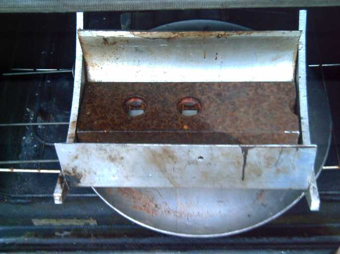
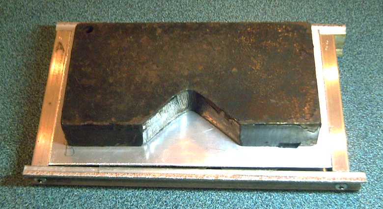
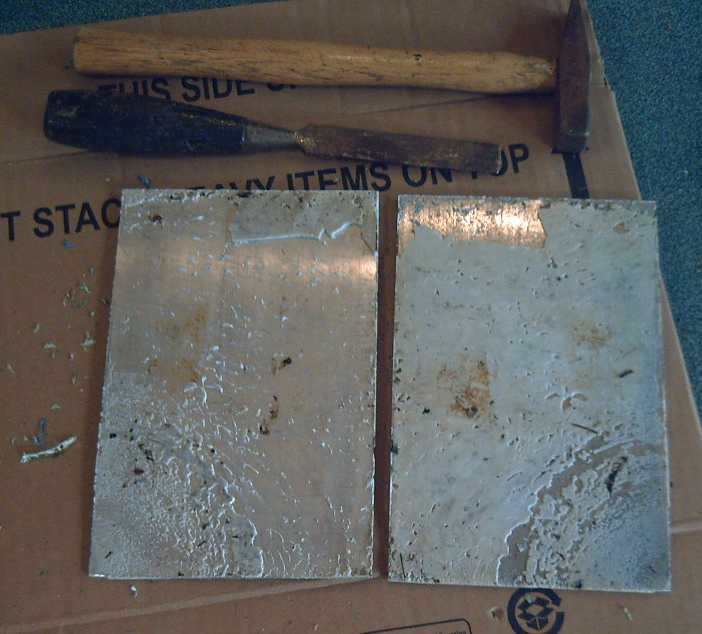
 A typical blade
casting: everything great except the outer/back corners.
A typical blade
casting: everything great except the outer/back corners.
 Typical molding out of
the oven.
Typical molding out of
the oven.
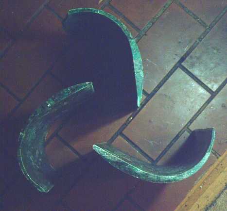 Potential Rotor
Layouts: Variation #1
Potential Rotor
Layouts: Variation #1
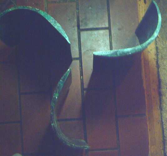 #2
#2
 #3 (not a very likely
looking setup!)
#3 (not a very likely
looking setup!)
It ended up
somewhere between 1 and 2.
[14th] I finished breaking out the innermost (of 3) piece of glass in
the oven door, put some fiberglass insulation in the ~1 inch space to
the next piece, cut a piece of steel to fit over it, and screwed it on.
I could hardly see into the oven anyway. Hopefully, if melting plastic
took longer because of the missing piece of glass, it would now be
shorter with the insulation.
In the evening I e-mailed the people doing the beach
cleanups with an update on my plastic molding. They replied saying that
the thousands of pounds of ropes and nets were all going to be removed
from the island Monday, so I had better get what I wanted Saturday -
tomorrow! Egads!
[15th] I hooked up the utility trailer to the Toyota Echo and picked up
a few hundred pounds of ropes. I hadn't tried the nets yet, but I knew
the ropes worked, and either way I could get all I would care to carry.
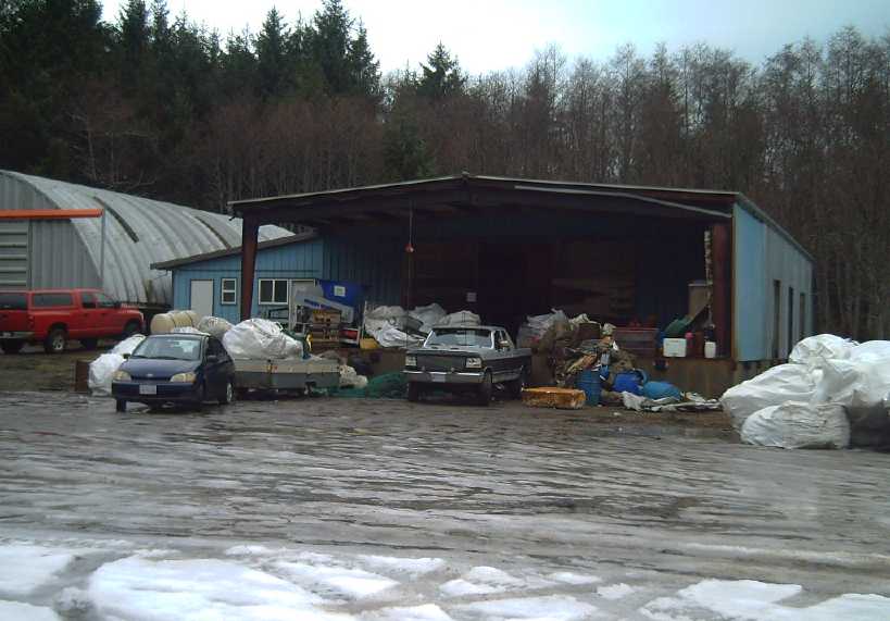 Operations yard for
cleanup of plastic off remote Haida Gwaii beaches.
Operations yard for
cleanup of plastic off remote Haida Gwaii beaches.
Contractors have picked it up with boats and brought it all here.
(My blue car and big "utility trailer" [hacked up tent trailer] at
left.)
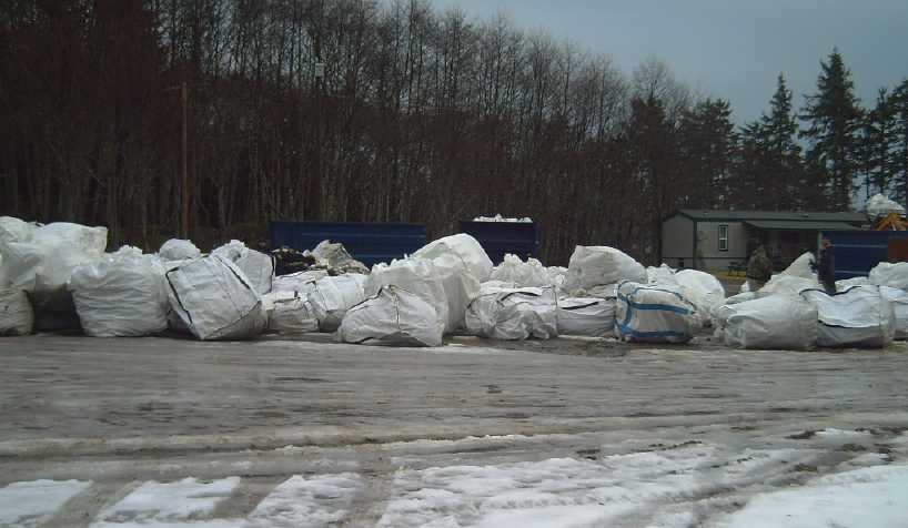 Forklift sized
bags of plastic - at leat one huge flatbed truck load had already been
removed.
Forklift sized
bags of plastic - at leat one huge flatbed truck load had already been
removed.
The bags are at least sorted into different materials. A forklift is
filling the blue bin (far right).
I am pleased to be making (hopefully) good use of some bit of this
mountain of waste material.
But the real mountain of waste plastic, with huge excavators crawling
like ants around on top of it, is on the BC lower mainland.
I essentially emptied one of their big white forklift
bags. Short bits and rope frayed ATRS are just as good as any other,
and
actually need less (or no) cutting to fit into the mold.The rest (and I
saw a truckload already on its way as I drove down) is going to
Vancouver on the North Arm barge from Masset. In 6 months or a year I
may be sorry I didn't take more and that it's all left the island, but
in case I don't actually produce windplants I already sure have a lot
of bits of rope.
After that I went into town. Two little BLDC motors I'd
ordered thinking they might make good generators for the windplants,
were in the mail. I did some quick tests.
RPM (with
Multi-speed
drill press)
|
VAC
(any
phase)
|
Load
|
Watts =
V^2 / R
|
Notes
|
620
|
3.2
|
open
|
-
|
Easy to
hold stator
|
1100
|
6.0
|
open
|
-
|
(with rotor
turning in drill
press chuck)
|
1100
|
5.7
|
10 Ω |
3.2
|
Resistance to
holding stator
from turning
|
1100
|
5.5
|
5 Ω |
6.1
|
More
|
1100
|
5.4
|
3 Ω |
9.7
|
and |
1100
|
4.0
|
1 Ω
|
16.0
|
more |
1100
|
3.2
|
.5 Ω
|
20.5
|
resistance/pull |
| 1720 |
9.7
|
open |
-
|
|
| 1720 |
8.7
|
3 Ω |
25.2
|
|
| 1720 |
6.4
|
1 Ω |
41.0
|
|
| 1720 |
5.4
|
.5 Ω |
58.3
|
greatest
resistance to
holding stator
|
I didn't care about frequency because I'm just going to
rectify it with a 3-phase bridge. To run a DC to DC up converter it has
to be over 8.5 volts. While that needs to be modified to the DC value
from all 3 phases, let's just say I should be aiming at around 1500 RPM
from say 200 RPM from the windplant rotor as a starting point in low
winds. The voltage can go through the DC to DC converter to say 13.5VDC
for charging 12V batteries or to about 40.5VDC for 36V. No doubt the
converter will manage whatever power it is getting from the windplant.
(or maybe an MPS7210A boost charge controller? But they need about 15
volts in. DC to DC and then MPS71210?)
So it needs about a 7.5 x mechanical speedup. How?
Anything is going to have some friction. How to get such a large
speedup in one step? I have those poly-V belts and ~2" pulleys. the
rotor part could run on a 15" flat or 'barrel' pulley of plywood
(prototype) or molded PP on the rotor axle. Or maybe a simple rubber
wheel running on a big PP wheel? Like, 1" and 7.5"? or something like
that. (Preferably that won't slip in a strong wind & generating say
100 watts.)
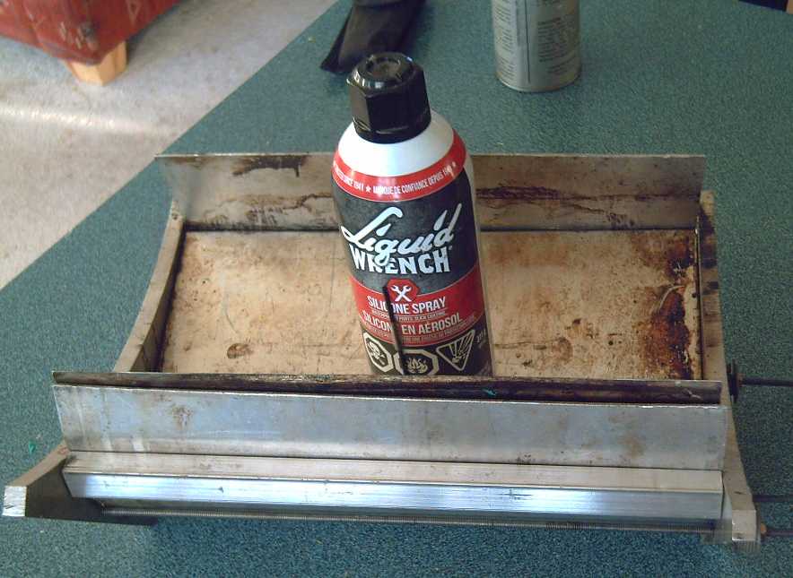
[16th] I drilled and threaded holes and put an alium. bar across the
back of the mold to support horizontal force pressing backward. The
other part to that is... how to get that force? Maybe I should cut a
piece to what I hope will be the exact length to supply it?
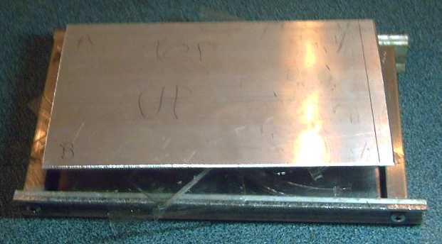
Fat alium. bar across
back to help hold curved form upright
Take 16 I put 525 grams of rope in the mold and put it in the
oven. I used some yellow and some blue rope too. The resulting colors
were visible but not very bright.
I had hoped the door insulation would reduce the time
needed in the oven, and I set the timer for 55 minutes instead of 60.
But it wasn't melted. Another 10... and another 10... and another 10.
It took almost 1-1/2 hours! The element looks the same brightness
AFAICT by eye, so my best guess is that I'm getting it so hot that the
insulation around the oven is withering. Maybe I need to replace the
(surely) fiberglass insulation with rock wool? I'll take a side off the
stove and see what I can see. I don't see why it shouldn't be possible
to melt the plastic in maybe 30 to 40 minutes. (After 15 minutes
cooling with the oven door open, the "oozed" plastic was still quite
soft to the touch of a screwdriver. So it's obviously not going to heat
up and cool down in 5 or 10 minutes.)
There was a little more edge oozing. The top corners were
still not filled, but the unfilled area was smaller. Maybe I
should try 550 grams? Or, if I could get thinner cracks between
the top and the sides, and more force against the back, less plastic
should ooze out around the edges. Since it would be hard to expand the
top piece, I should probably sand the bottom piece just slightly
narrower. Another thing that might be abetting poorer results is that
except for the first 2 or 3 times, I have repeatedly forgotten to spray
on the silicone lubricant. The ones that filled the corners best
probably had been sprayed. Maybe the problem will magicly go away if I
do? I put the can in the mold so I don't forget next time.
[17th] I did a bit of sanding on the edges to narrow the bottom piece a
trifle. It had been about 1.5mm(?) wider than the top. I probably got
it below 1mm max. (But if the top is Any wider than the bottom, it will
probably jam instead of sinking down as the plastic melts!)
I looked at the oven. The far side had sprung away at the
front, leaving a gap. (Remember where I got this free stove.) That had
to be letting cold air in! The insulation inside of it looked all
right. So I just sprung it back on and put a stake next to it to stop
the bottom from springing out again.
Take 17 I put in 525 grams of PP again, hoping less would ooze
out the sides and it would go into the outer corners instead, and
sprayed the mold with silicone lube. I set the oven timer for an hour.
Nope. Add 10 minutes (looked like it was close) and add 10 minutes
again. Then, still not seeing anything coming at the top corner edges,
I unplugged it but left the door closed for another 10.
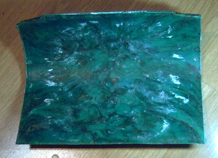
 Another Mold (something
of a sideline!)
Another Mold (something
of a sideline!)
I also wanted to try something besides rotor
blades. The idea of greenhouse wall and roof panels or panes was
enticing. There are clear PS and PP packages, but most "display" food
comes in clear PETE, so I chose that. I looked around for scraps of
alium. and picked some small pieces to make a simple box mold about 157
by 212 mm. Just a test size. I can't see such small pieces being of
much use. I suppose because it was small, it seemed proportional to
make it with low walls. In doing that, I neglected a key "Plastic
Recycling 2.0" point. That is, that whatever the size of the mold, if
you're going to throw in chunks of plastic, the sides have to be high
enough to contain them. To accommodate bulky transparent food
containers, the sides should have probably been about 3 inches tall.
 Because they are so short I had to cut
the containers way down into
pretty flat bits, and even then I had to scrunch them down and put the
weight on top to get them "contained" - more or less.
Because they are so short I had to cut
the containers way down into
pretty flat bits, and even then I had to scrunch them down and put the
weight on top to get them "contained" - more or less.
[18th] Oven: I took the back off and checked the oven element.
Still 9.33
amps: 2240 watts. No change there. I put in the little tray of PETE
with a single 8 pound weight on it. In just 10 minutes the lid had sunk
into the box. I left the oven on another 10 and took it out. I was too
early. And it looked a little thin, so I added some more bits.
Perhaps the insulation just under the floor of the oven
and the heater element was burned or melted? Could I open it? I tipped
the oven
on its side. Water came out. It looked like nearly everything would
have to disassemble before the underneath panel, but there was one
little
finger hole and I could feel that the oven floor insulation was soaking
wet! That would certainly ruin its insulating capacity, and explain why
it seemed to be taking longer and longer to melt the plastic. Of course
I should have the stove under cover. Easier said than done.
Perhaps I could put something over it? What? I ended up with a piece of
PE for a tarp, held down by a couple of boards. Well! I could have done
that easily in the first place!
Take 18 #17 had less PP oozed out the cracks, but it hadn't
fully pressed home on the right side again. And I noticed later that
#16 hadn't pressed quite down at the left-front corner. It was a little
thicker there. The extra
thickness in each could explain why there still wasn't enough plastic
to fill the top corners. Need more weights, again? I had dropped it
down to 30 pounds again. It seemed so absurdly heavy for what it was
doing. Maybe it really needed 35 or 40? Then maybe part of the reason
for long times was insufficient pressure to squash the PP into place
until it was hotter than just "melted"? Maybe that was adding 5 or 10
minutes?
I cut another 30cm, 10 pound piece of grader blade, which
also
left an end that was 6.6 pounds. Then I cut a bunch more pieces of the
green PP rope. I put in about 535g of rope and about 35 pounds worth of
weights on top. At the same time I put the little PETE test mold in
again with 9 pounds on it, and set the timer for 30 minutes. The oven
rack was sagging even with a piece of brick supporting the middle.
 After 30
minutes the sheets of PETE had all squashed down
pretty flat, but they hadn't actually melted: they were still separate
sheets that didn't stick to each other and merge into one thick piece.
I put it back in and set the timer to 30 more.
After 30
minutes the sheets of PETE had all squashed down
pretty flat, but they hadn't actually melted: they were still separate
sheets that didn't stick to each other and merge into one thick piece.
I put it back in and set the timer to 30 more.
By this time the sheets were at least merging into each
other. They also seemed to be turning from transparent to gray. I hoped
and thought they would become clear again once fused into a single
sheet between the alium sheets.
 I gave it
another 15. That was apparently too much. I hadn't
put stoppers inside, counting on the viscosity of the melted plastic to
stop the weight. But the PETE was so much thinner than the PP that it
came out every tiny crack around the top and bottom. And turned light
gray.
I gave it
another 15. That was apparently too much. I hadn't
put stoppers inside, counting on the viscosity of the melted plastic to
stop the weight. But the PETE was so much thinner than the PP that it
came out every tiny crack around the top and bottom. And turned light
gray.
And it stuck to the
alium pretty hard. I had to unscrew all 4 corners and hit them with a
screwdriver handle, at which point the side pieces would snap off
suddenly, like glass.
(I had again neglected the silicone lube spray on this one.) I put it -
the top and
bottom with the PETE sandwiched between, gluing them together - in the
freezer. That didn't coax them to separate, but a chisel and a hammer
did so without bending up the alium. sheets.
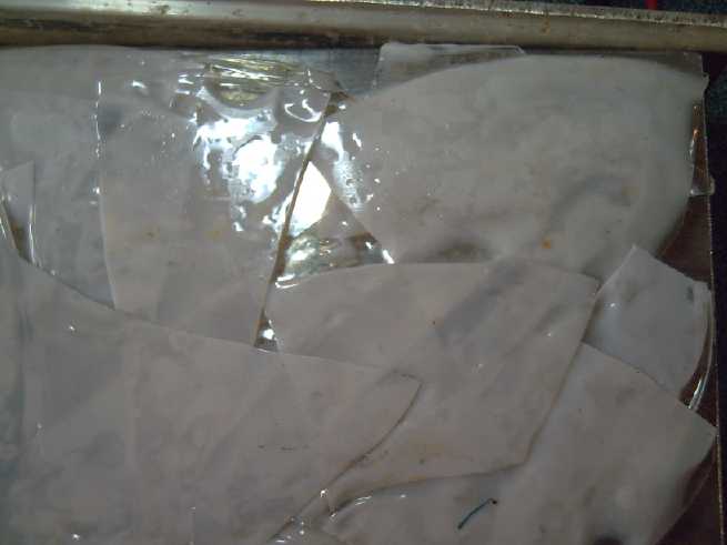
Clear PETE Not Transparent!?!
 Some of the
thin layer (< 1 to 2 mm thick) still inside stuck to each face. It
was useless, and quite a challenge to chisel off in little bits. Along
with becoming brittle as glass, the PETE
including inside the mold had lost its transparency and become a light
gray color. In fact it seemed to
be doing that even before it had completely melted. I could hardly see
light through a 1.5 to 2.0mm thick shard. So much for PETE! I don't
think I'll try it again.
Some of the
thin layer (< 1 to 2 mm thick) still inside stuck to each face. It
was useless, and quite a challenge to chisel off in little bits. Along
with becoming brittle as glass, the PETE
including inside the mold had lost its transparency and become a light
gray color. In fact it seemed to
be doing that even before it had completely melted. I could hardly see
light through a 1.5 to 2.0mm thick shard. So much for PETE! I don't
think I'll try it again.
That shattered my dream of making
transparent PETE greenhouse panels - at least with my technique. The
brittleness merely
underscored the unsuitability. Just as well I did a small mold and not
a big "greenhouse panels" size one to test the idea out!
There are transparent PP and PS food containers, but they
are rare compared to PETE. Even if one or both of them work, it's hard
to imagine collecting enough scraps to make a good part of a
greenhouse, let alone make it an enterprise.
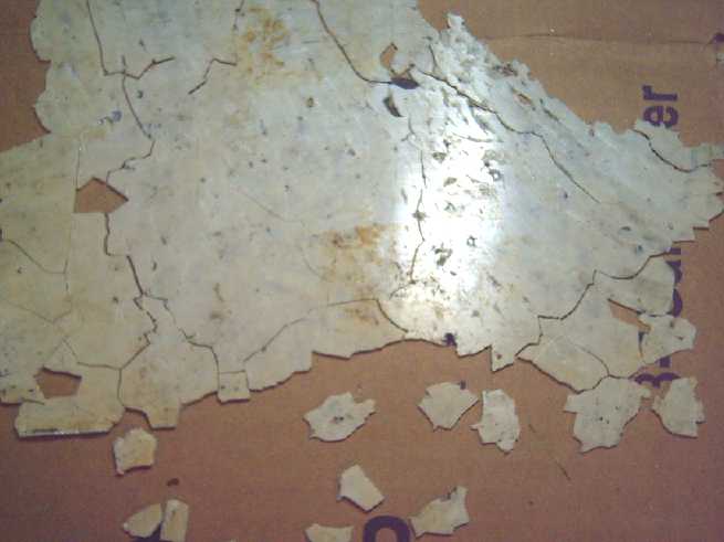 When I scraped
them off, the pieces made an interesting jigsaw puzzle. The clues were
the thickness and general shade of the pieces. (It helped that the
bottoms were darker than the tops.) The smaller pieces usually looked
like they just couldn't be the right fit until they were actually in
place and the cracks disappeared.
When I scraped
them off, the pieces made an interesting jigsaw puzzle. The clues were
the thickness and general shade of the pieces. (It helped that the
bottoms were darker than the tops.) The smaller pieces usually looked
like they just couldn't be the right fit until they were actually in
place and the cracks disappeared.
Moving on, the PP Wind Wall
was still a "go"... The "Take 18" blade had a lot of overflow in
the top middle, so much and so thick I had to cut it off on the bandsaw
rather than just breaking it off. And one top corner had filled. The
other one was almost filled. Maybe 550 grams of PP next time? Or, what
if anything could I do about the overflow? It also had not quite
flattened out at the front left, like #16. Maybe with so much
weight on top, it's bending the mold? (It's certainly bending the oven
rack! So the two mold 'feet' are probably not even.)
A wind wall with two 3 foot tall rotors will take 18
blades, so for the prototype I'll be using most of the ones I've made
regardless of flaws. Not to mention 3 of the best for the test rotor.
Finally Some Tests
I cut two 16"
diameter circles out of plywood (3/4" and 1/4") and measured off
120° positions. Then I found 8 and made 4 more small angle
brackets. (never mind making complex plywood shapes on the CNC router!
or by hand again.) I drilled holes and mounted three blades between the
two circles, at the positions and angles I thought would be about
optimum. It was 16" (OD) by 12" effective height.
I put it in the wind tunnel and got the
following results (Shop & OAT = +5°c):
Low: 50-58 RPM
Med: 84-88 RPM
High: 100-104 RPM
From last month, the 9.75" (OD) by 14" (effective blade height)
3-bladed test rotor gave:
Low: 56-57
Med: 86-90
High: 108-118
Being 16" diameter instead of 10", the similar RPMs
represent 1.6* more linear speed at the outer rim, which surely
represents more torque from the wider rotor better overcoming bearing
friction. And, putting some finger friction on the axle, it did seem to
have more torque.
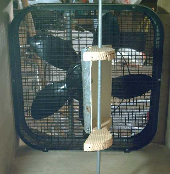
Then I put the stationary vane in front at 45° to aim
the wind. With the larger diameter rotor it was a little too narrow to
deflect all the wind from the returning side to the power stroke side,
but it still gave a good boost:
Low: 68-78 RPM
Med: 96-106 RPM
High: 128-136 RPM
Again the torque seemed at least marginally substantial.
It may only be a few watts, but again, the 3.1 m/s wind speed from the
fan on high is still below the 4 m/s cut-in speed of most windplants.
And if the rotor was 3 feet tall instead of 1 foot, I'm pretty sure it
would prove to be well over 10 watts, and with two rotors in the wind
wall, 20 or 30. It's the cube of the wind speed from there up. Double
the speed to a good stiff breeze (6.2 m/s): 160 or 240 watts.
[20th] I started thinking that if plywood would eat 1.5 inches out of
each 12 inch blade (12.5% power loss!), maybe I should make the blade
supports differently than I had planned. Well, they will be PP, so
there's time to design them differently than a flat slab.
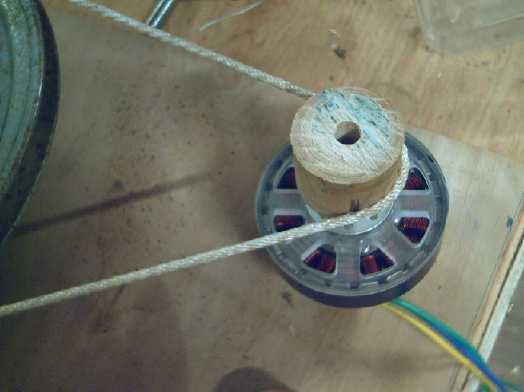
Generator Coupling
I had been wondering how to connect the generators to the
axle of the rotor with a speed-up. A flat belt might be good, but PP
strapping was too heavy for this. Where to find a light one? Then I
thought of just using fat string or thin rope. It might be tricky, but
the ends could be melted together to make a loop, and an idler wheel
could apply tension. And it might even be arranged that it would slip
with sufficient resistance before it burned out the generator in a
storm? I would need some pretty ordinary pulleys for thin rope! I
decided to lay it all out on a small piece of plywood that could be set
on top of the wind tunnel to test it.
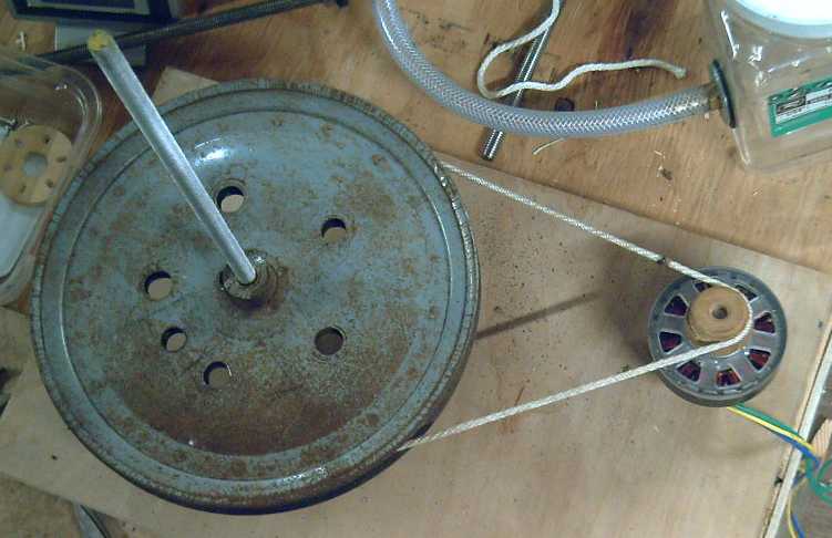
I took a piece of fat string and melted the ends together.
There was a bump every time the join passed the small pulley, but it
didn't break apart. I found a 9" V-belt pulley and added some brass
tubes to shim it down from 1/2" to the 3/8" rotor axle. I couldn't find
two small V-belt pulleys I bought a while ago for the bandmill project.
So on the generator I tried a round piece of wood, which I turned on
the lathe to what I thought would be suitable, but the cogging and
friction of the generator, multiplied by 10+ by the speed increase
ratio, prevented the rotor from spinning. And if I started it by hand,
it soon came to a stop. I tried the other end of the piece with a
somewhat larger diameter, but it still wouldn't start. (If the rotor
had been 3 times taller, it might have.)
Then I tried a 3+" V-belt pulley I had on hand. That
turned, and gave 0.2 VAC out. The rotor wasn't turning very fast. I
really think I want magnets right on the rotor axle and a non-cogging
stator -- a low speed generator that has no effect on the rotation
until one tries to draw power out of it.
 smallest pulley
 a bit larger
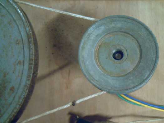 3" V-belt pulley
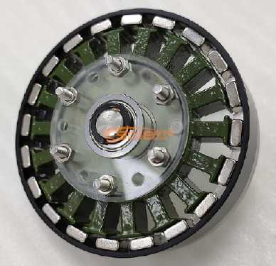 The poles and magnets
construction of this small motor
The poles and magnets
construction of this small motor
Wind Wall... or WATER Wall ?!?
[21st] I drove to Masset to buy some machine screws no one seemed to
have in QC. As the highway passed by Masset Inlet with its strong tidal
flow running, it suddenly occurred to me that the wind turbine should
also make a great low-speed water turbine, and that the wind wall could
also be a great water wall! There seemed to be a some 'fortuitous'
features that could make it a great fit for marine use:
1. With the generators at the top end of the axles as planned, they
could be out of the water while the turbines were in it.
Counter-rotating turbines would neutralize (or at least limit) any
tendency to pull to one side.
2. I had designed for torque and power at the lowest possible wind
speeds, but obviously a 2 meters per second wind doesn't have enough
force to do much more than charge a cell phone or light an LED.
However, a 2 meters per second water flow would certainly have a lot of
power! Air = 1.25 Kg/m^3. Water = 1000 Kg/m^3. So
power at the same flow rate is 800 times more.
3. It's mostly made of polypropylene plastic! With, say, UHMW (& ?)
bushings instead of ball bearings, it would last a long time
underwater. The metal shaft could be replaced with PP or stainless
steel.
4. Having low-speed turbines with blunt faces, it would probably allow
small fish to pass through without harm. With a "cow-catcher" to
deflect surface logs and debris, and the turbines underwater, it
probably wouldn't be very prone to getting clogged. (If necessary,
grilles can be deployed in front.)
In addition, the fixed "wall" enclosure allows for diverse
deployment options. For example: attached to any sort of floating
vessel, or placed in a creek with ropes to hold it in position. It
could be fixed in place underwater, with tall sides on the wall and
long shafts holding the generators far in the air for varying water
depths including for tides. With floats attached to the sides, it could
be tethered in a river or other flowing water (eg, Masset inlet) either
from shore (with the programmable rudders), from a fixed anchor or from
an anchored vessel.
Then there's that idea from the Faroes (TE News #163)
about having it tack back and forth behind its moorings to gain lateral
speed and increase the rate of flow through the turbines, perhaps from
2 meters per second to 3.
The potential prospects suddenly seem far more exciting
than a simple home windplant! Maybe we won't need to buy our future
tide power units from Scotland after all!
Insulated PETE Greenhouse Panels?
I also had another idea for the polyethylene terepthalate
(PETE / PET) greenhouse panels. It may be a bit flakey... or might it
actually make a
better product?
Before it started to melt and turn gray, in the oven for
just 10 minutes the PETE plastic had essentially flattened from its
various container shapes, still transparent but now loose, flat sheets
- not stuck together. Perhaps one could use this: create the flat
sheets in a box mold and set several layers on top of each other. Then
stamp them every 2 or 3 or 4 inches apart with something hot that would
melt the stamped points together. Perhaps in a hexagon pattern? And
maybe stamp the edges. They would no doubt be opaque gray at the points
where they were stamped, but in between they would be several
transparent layers with thin trapped air spaces (...or probably open at
some edges). This would probably be stronger than a single thick sheet,
and it would have something more: it would have an insulating value. It
might have a higher "R" value than (eg) 2-layer coroplast or
polycarbonate sheets.
Okay, the pattern stamping would require some extra
equipment that I have no intention of trying to create myself. (Unless
it could be done on the CNC table?) But I
still might experiment a bit and see what could be made!
As far as actual work of the day, I made a couple of small
but hopefully significant adjustment bends in the bottom piece of the
blade mold at the back. Hopefully it will have less melted plastic
oozing out the middle and better fill into the back corners.
[22th] Take 19, 20 I made another blade, using the plastic from
Take #1 and a couple of other bits to make 535 grams, and this time the
back end came out well - less excess came out in the middle and the
corners were filled. YAY! 70 minutes seemed to be the magic time for
the oven. Except for a few bubbles it was pretty much perfect.
Looking closer, one side didn't seem to have enough curve
- the fat part was too thin toward the left side. (Why does that keep
happening after I keep bending it to make it thicker?) So I bent it a
bit more (again) to fix that. Then I did another one. This time the
corners were missing again. With the fat part fatter, it seemed like
there just wasn't quite enough plastic. 570 grams next time!
[23rd] The next blade (I'm going to stop counting) didn't seem to have
pressed down all the way on either side, so again it had void corners.
Hmm...
[24th] I put another blade in the oven. Much "miscellaneous" bits of
rope with lots of frayed strands. It looked like the corners were going
to be missing again. I unplugged the oven, but this time I threw
another 9 pound weight on top of the 29 and left it with the door
closed another 8-9 minutes. Bingo! When I opened the door it
had squeezed down more and plastic was oozing out everywhere including
three corners. The fourth turned out to be all but filled, and yet the
right hand side (still!) hadn't pressed all the way down.
Didn't I already figure out once before that it seemed to
need 35 or 40 pounds? I seem to have taken a very long time and far too
many tries to learn what should be two pretty simple variables: (A) the
length of time needed in the oven and (B) the amount of weight
required. But it is hard to comprehend that it should need so
much weight! Oh, and yes: a little silicone lube on the mold surface
helps the piece come out more easily.
I had been thinking about how they mount, and that a solid
circle top and bottom would probably be best, so the rotor would be
like a 'spool', with no wind (or water flow) going up or down instead
of across. But how to accomplish that? The obvious best would be a
solid spool made of one piece of plastic: circle top, 3 blades and
circle bottom. That seemed well beyond the capabilities of "plastic
recycling 2.0". But perhaps I could mold the blades with a flange on
each side? Those could much more easily screw or bolt onto plain circle
end pieces - molded or just cut out of plastic sheets. That meant
changing the mold to add the flanges... hmm! ...or should I stick with
the original plan of a complex shaped mounting piece like the test
pieces? Somehow that seems more doable and will probably work just as
well.
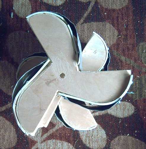 The rather complex
shape "hub" pieces to attach the blades to
The rather complex
shape "hub" pieces to attach the blades to
(On the smaller test rotors)
If I was going to make that, the blade positions and
angles would be fixed, built into the mold. It would be best if that
was the optimal shape! So I went out to the shop for 3 hours trying out
different blade positions and angles to see what gave the highest RPM,
or the highest RPM for the diameter. I took out the stationary vane as
a potential "wild card". The variableness of the results at the best of
times made things tricky, but I finally concluded that my original
chosen adjustments actually seemed to be best. Nothing else seemed
better, and some didn't seem as good. RPMs for all positions tried were
about 86 to 98, and the original gave 96-98.
[26th] I went back to thinking the "spool" idea was best. At the
thickest points of the blades, stainless steel screws - 1 or 2 - could
be put through to hold them to the side circles. Something else would
have to be made to hold a couple of screws at the thinner outside
areas. "L" brackets would work. Ugh! Well, I'll think about it later.
Another choice might be to epoxy everything together. I didn't want to
add an impurity to the PP in case of later recycling, but it might be
the practical and strongest solution.
Now... how to make those big PP circles for the top and
bottom? I dug out a 1/4 inch thick circle of alium. Jim at AGO had
given me some years back. 404mm diameter. Turned "perfect" on a big
lathe. I couldn't have made anything more perfect! (Although I had it
because it said "Wobbels - no good.") So there was the lid to the mold.
The bottom could be any shape - ie, square. That left the sides. They
would have to be made of maybe 1/4" alium, bent around in a perfect
circle to match the top. Maybe 2.5 or 3 inches tall. 1269mm (49.97")
long. This rim would be screwed to the bottom for doing the molding. If
there was some way to hold it to the bottom, the rim could perhaps be
thinner. But 1/4" would best ensure a smooth, even and solid curve.
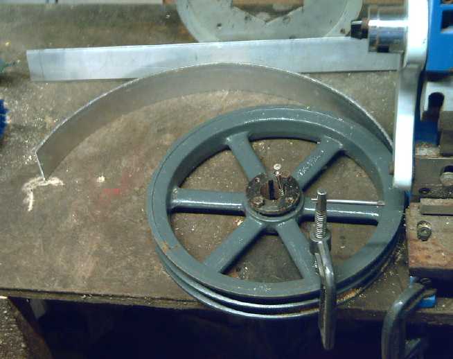 Out in the
shop I found a piece about 1/8" thick, 4" wide, and 46" long. If split
it into two 2" wide pieces each 26" long, it would be long enough. (I
had nothing 50" long.) I thought that should bend smoothly enough and
as I had to bend it by hand, it would be about all I could handle
anyway. I would have to use angle brackets or something to hold it to
the bottom piece.
Out in the
shop I found a piece about 1/8" thick, 4" wide, and 46" long. If split
it into two 2" wide pieces each 26" long, it would be long enough. (I
had nothing 50" long.) I thought that should bend smoothly enough and
as I had to bend it by hand, it would be about all I could handle
anyway. I would have to use angle brackets or something to hold it to
the bottom piece.
I cut the pieces and bent them around a 12" V-belt pulley,
fastened to a bench beside the notorious sheet metal machine as an
anchor. They sprang back too much, and I ended up with a 10" pulley.
That made the curve just a bit too small, but by an amount easily bent
back by hand. Then (having left enough length) I bent two ends to
overlap and put screws through to hold it together.
[27th] I cut a square bottom piece just
a bit bigger than the ring. Then I polished the faces and then did the
rim screws. I cut the ends off the screws so they wouldn't stick
inside, which would stop the lid from pushing down. I put 3 machine
screws through the lid at 120° both marking where screws would be
to screw into the blades, and to set a stopping height within the mold
for the melting plastic. I had planned to make "L" brackets to hold the
sides to the bottom, but then I thought of just using some spring
clips, which I made from some flat springy metal strips.
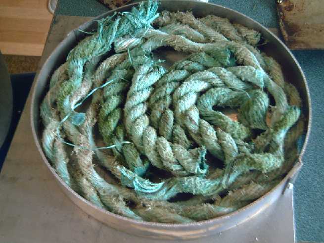 1210 grams of PP
plastic (too much!)
1210 grams of PP
plastic (too much!)
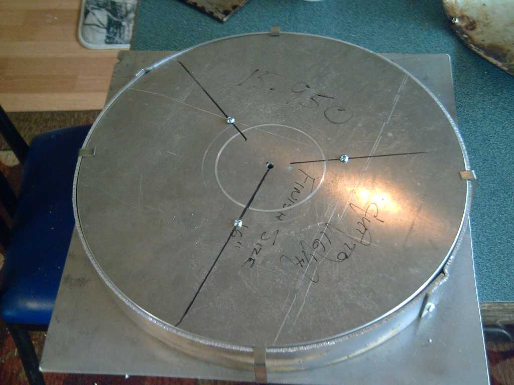
Top just fit on
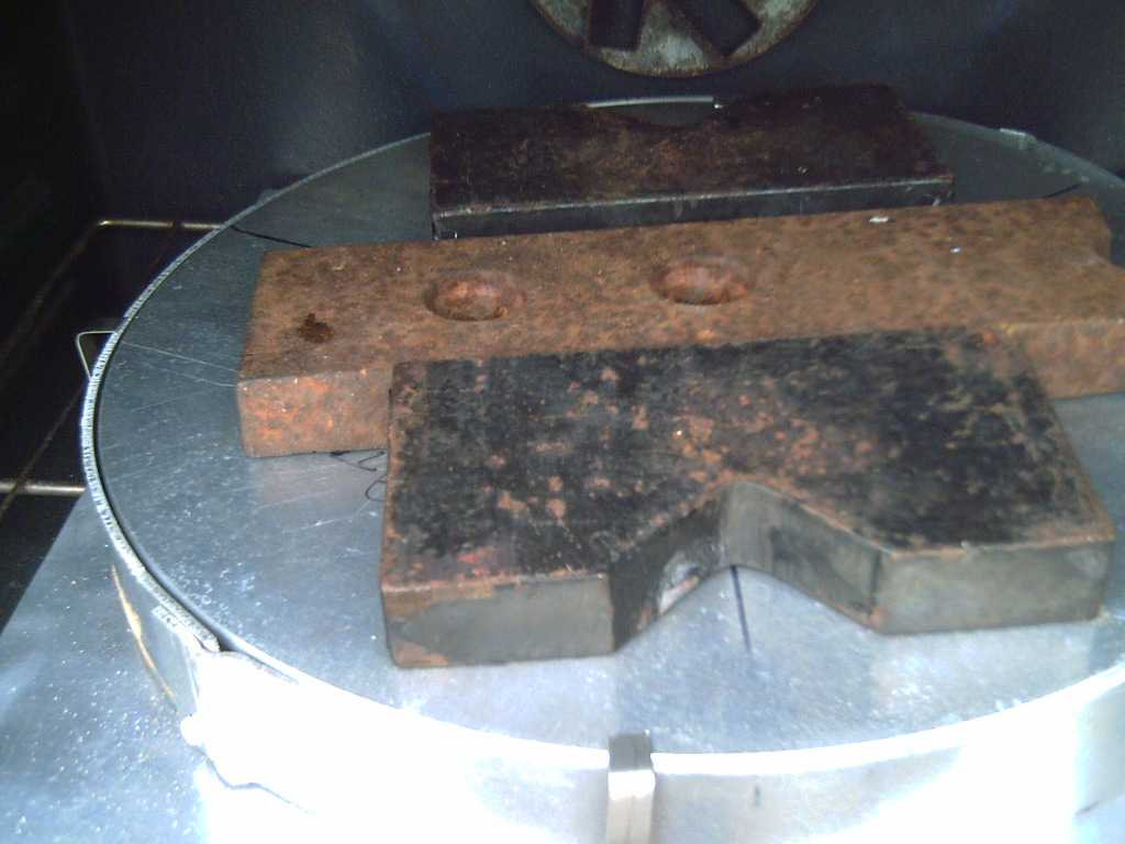
In the oven
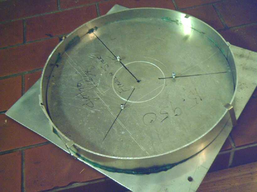
After baking
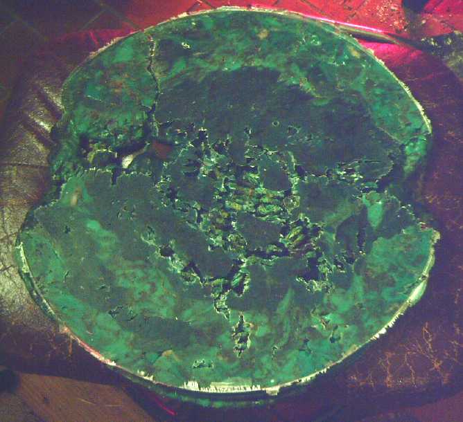
Half baked!
In the oven I set it on the same pizza dsih I had used for
a drip catcher base for the blades. It was the same diameter as the top
piece and the ring. Of course, that supported it all the way around the
edges but not in the middle. I ended up using the same ~38 pounds of
weights as for the blades. It was harder to tell what was going on than
with the blades, but in 65 minutes when a fair bit of PP had oozed out
one area I turned the heat off.
The result was disappointing. But the main problem seemed
to be that it hadn't completely melted. Also, the flat bottom had
become warped, something like a shallow dish probably from having no
support in the middle.
Later I put it back in the oven to redo it. But the warped
bottom piece looked like it would let a lot of PP ooze out one side
area. It seemed it needed a thicker bottom to stay flat, perhaps 1/4"
instead of ~.085". I don't have such a piece, but the TOP was 1/4"!
Very little had oozed out the narrow cracks between the top and the
outer ring. I set some fat supports in the middle so the edges wouldn't
touch as it sank down, and turned the whole thing upside down. I set
the timer for 75 minutes and hoped. It wasn't reassuring that any that
came out was likely to run down and drip onto the burner.
I finished editing pictures in 70 minutes and checked.
There was enough smoke coming out to make me nervous, so I unplugged
the oven and opened the door.
When it had cooled enough to look, it was much better
melted, but not ideally. The bottom (now top) piece being bowed out was
no help. However, it was 6mm thick at one edge and about 14mm opposite
- quite lop-sided. Apparently the machine screws were too near the
center and weren't keeping the lid(?) level as the plastic sank down.
(And there was just too much plastic.) I could put in three more nearer
the rim, but I had to figure out exactly where, in relation to the
first three, and to where the blades would sit. And it obviously needed
a thicker bottom piece.
[29th] I decided 1/4" was about the right thickness rather than 1/2" -
which was the thin side of my lop-sided circle. But I needed a thicker
bottom piece for the mold, the one I had having formed the shape of a
dish. So I put that aside for the moment.
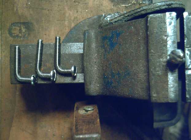 For doing the
screws out toward the edge, I conceived that instead of "L" brackets,
maybe I could bend some stainless steel machine screws to 90°. Then
it could be inserted through the blade, and the up (down) bend could go
through the top (bottom) and a nut be put on, which would tighten the
blade into place.
For doing the
screws out toward the edge, I conceived that instead of "L" brackets,
maybe I could bend some stainless steel machine screws to 90°. Then
it could be inserted through the blade, and the up (down) bend could go
through the top (bottom) and a nut be put on, which would tighten the
blade into place.
The bolts bent more easily than I expected, just in a vise
with a small hammer. And if one tapped them crooked a little, then
loosened the vise and raised them a bit, then bent them farther, then
repeated that 3 or 4 times until they were at a right angle, the bend
was more gradual and they looked like they stayed plenty strong.
I asked my neighbor if he
had any stainless steel shaft lying around. Instead I got a plastic
pipe. It was 1 inch inside diameter. I was thinking it was a bit thick,
then I realized that I could use it as a coupler for the 1 inch shaft
of my "Improved Piggott alternator" to connect it to the rotor. If I
slit it I could tighten it on with hose clamps. (When did I make
that... 3 years ago?)
That solved a piece of the puzzle. With the non-cogging,
low friction alternator good for kilowatts, plus putting the rotor in
flowing water, the unit should spin and put out some real power!
...once the outer frame was done and all was assembled, of course. I
would use a short stainless steel shaft at the bottom and make a UHMW
bushing to hold it. That should work and last well in water, even salt
water.
[Feb. 2nd] On the 1st Steve cut me a 1/4" thick bottom piece, a 17"
octagon, from a big sheet he had. The extra size left a lip to catch
oozing plastic. I made 8 spring clips to hold the outside rim to the
bottom and minimize PP oozing out.
I put 3 more machine screw holes at the positions I
estimated the bent screws should go, which were also to help keep the
top level as it descended with the melting plastic. So it had six
#10-24 screws protruding 1/4" into the mold cavity through the lid.
Then I bandsawed off half my original disc of PP to 610
grams instead of 1210, this time intending to make it 1/4" thick
instead of 1/2". I put that into the mold, put the lid on and did up
the clips, and put it all in the oven with 25 pounds of weight on the
lid. It seemed to be done in 60 minutes so I opened the door and
unplugged it. After 10 minutes I unscrewed the six lid screws.
(Removing protruding screws (at least all but one) is necessary because
the plastic shrinks more than the alium. as it cools, and it would
crack at the screws as it contracted between them.
I should have noticed that no plastic had oozed out
anywhere. When I took it out, I discovered that it had shrunk down into
a flat blob, but it hadn't quite flattened out completely and filled to
the edges. Of course it was already a flat blob, but I could see it had
sunk down more. 5 more minutes probably would have done it! I tried to
make a mark around the inside of the rim with a felt pen to show just
where the lid should drop to when it was done. I sprayed in some
silicone spray, put it together again, and back in the oven. As it was
still quite warm I set the timer for 50 minutes to check it then. (I
think I had to leave it on for another 5 or 10 minutes.)
The mold after pulling it out of
the oven
The circle. There were a few
small voids,
notably near some of the screw holes
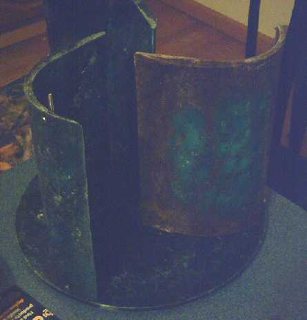 I used 3 of the bent bolts and
drilled three
blades, and semi-mounted them
I used 3 of the bent bolts and
drilled three
blades, and semi-mounted them
The silicone spray had created a mist when I sprayed it on
the hot alium. and it bothered my lungs. The hot plastic smelled some
too. Even the cooled parts could still be smelled a bit for a day or
so. I resolved that unless the weather or the bugs were really awful I
was going to do everything outdoors until I had a cool or cold piece of
plastic. Maybe I'll just keep everything out in the shop? Or maybe a
work table in the carport would be a good idea?
[Feb 3rd] I tried casting another rotor but it visibly was way thicker
on one side and the plastic hadn't reached the edge on the other. Again
I think I hadn't given it enough time. I didn't even take it apart.
Later I did up the screws and put it back in the oven, this time for 75
minutes. This time much more plastic had oozed out the cracks and it
looked like it was down flat. It turned out to still be thicker on one
side than the other, but I decided it was "close enough". The rotor may
need a weight attached to balance it. Next time I'll use a little less
plastic. (585g instead of 635?)
Also I bought a remote laser temperature reader and got
readings of 262 and 266°C [511°F] on the top of the mold when I
pulled the piece out. In future I can check it and make sure it's up to
that range to guess whether the plastic has fully melted yet, instead
of running blind.
Here it is -- the immersible
solid
polypropylene turbine!
(with only 3 bolts, the top's edges not yet trimmed/sanded, and no axle)
My
Solar
Power
System
The 31st was sunny, and it occurred to me that the cabin
solar now had 1220W of panels driving a 700W grid tie. There was just
470W being made in the still low winter sun, but soon the inverter
would be limiting the power output, if it wasn't already. I took the
old 1000W inverter back out and re-installed it, and put two panels
(610W) on each. I know the Y-Solar "1000W" inverters work best with the
lightest load, but it occurs to me I could add another panel for 1525W
at the cabin and still be under the rating for both inverters. I don't
suppose it made much difference to the day's production, much less to
the month's. (Now if only there wasn't a travel trailer and an RV with
1100W of electric heaters plugged in down there, using far more than is
ever made in winter!)
If I do get around to installing more panels, I'd like to
mount them more upright to get more fall-winter-spring production,
instead of just the easy mounting: bolting them flat on the 15°
slope roof. And I'd most like to try putting some on the roof at the
north end of the east garage, where I think there's the least tree
shade of anywhere available.
Daily/Monthly/Yearly Log of Solar
Power Generated [and grid power consumed]
(All times are in PST: clock 48 minutes ahead of sun, not PDT which
is an hour and 48 minutes ahead. (DC) battery system power output
readings are reset to zero
daily (often just for LED lights, occasionally used with other loads:
Electric car, inverters in power outages or other 36V loads), while the
grid tied readings are cumulative.)
Solar: House, Trailer, (.DC@house) => total KWH [grid power
meter reading(s)@time] Sky conditions
Km = electric car drove distance, then car was charged.
December
31st 2443.40, 0001.32, .37 => 0.41 [91033@17:30] -4,-2° again
January
01st 2443.60, 0001.85, .36 => 1.09 [91080@16:30] +3° (Yay!) Snow
melted off cabin roof & panels, but only partly off house roof
panels.
2nd 2443.70, 0002.17, .29 => 0.71 [91134@17:00] +1°. Still
snow on house panels.
03rd 2443.75, 0002.22, .05 => 0.15 [50Km; 91186@16:30] -1 to
+2°,
snowing, wind.
04th 2443.75, 0002.22, .05 => 0.05 [91256@24:30] -2° or so.
Brushed off 5 panels during day for DC system.
05th 2443.78, 0002.22, .05 => 0.08 [55Km; 91297@17:00] -3°,
Still snow
all over.
06th 2444.42, 0002.22, .39 => 1.03 [91364@17:30] -6° to -3°,
snowed overnight. Mostly sunny. Running 12W DC light panel for plants.
07th 2444.93, 0002.23, .35 => 0.87 [91429@17:00] -7 to -1°,
sunny AM, no wind. A bit more snow.
08th 2444.94, 0002.23, .06 => 0.07 [55Km; 91497@17:30]
rain/snow/rain -2 to +2°. The snow is getting slushy.
09th 2445.10, 0002.34, .06 => 0.33 [91557@20:00] hit +5° heavy
rain most of day - snow is melting.
10th 2445.81, 0002.83, .23 => 1.43 [91597@17:30] +6°, some sun
around noonhour.
11th 2446.06, 0003.06, .14 => 0.65 [45Km; 91647@17:00] +2°,
clouds. Gosh, still almost no collection even with the snow gone off
the collectors?
12th 2446.50. 0003.42, .26 => 1.06 [55Km; 91701@17:00] +1°,
clouds, fog.
13th 2446.88, 0003.72, .24 => 0.92 [91756@17:00] Morr clouds, fog.
+3°.
14th 2447.45, 0004.12, .18 => 1.15 [91802@17:00] Tiny bit of sun in
AM, +6°
15th 2447.78, 0004.28, .09 => 0.58 [50Km; 91858@17:30] No sun today!
+3°
16th 2449.45, 0005.21, .12 => 2.72 [91909@17:30] Sunny for part of
PM.
17th 2451.76, 0007.01, .26 => 4.37 [55Km;91957@17:30] Sunny Day! -0
to +2° (nothing is thawing!)
18th 2453.29, 0007.79, .18 => 2.49 [92005@17:30] 0°
19th 2453.66, 0007.91, .00 => 0.49 [55Km; 92063@17:30] Dull, rain.
+5°. No more snow?
20th 2456.16, 0009.68, .00 => 4.27 [93105@18:00] Sunny except early
AM.
21st 2457.02, 0010.42, .30 => 1.90 [93146@17:00] Some sun. +8°
22d 2459.25, 0011.52, .20 => 3.53 [55Km; 93196@17:00] Some
nice sun. +7°
23rd 2461.31, 0012.44, .02 => 3.00 [93244@17:30] Some sun again (I
wasn't going to bother adding in the '.02', but...)
24th 2462.78, 0013.23, .09 => 2.35 [93287@17:30] Not much sun.
25th 2464.54, 0014.15, .08 => 2.76 [60Km; 93328@18:00] Hazee sun
throo claoodz az yoojyooil. +7°
26th 2465.44, 0014.49, .00 => 1.24 [93377@18:00] No sun today!
From the cabin, a suspiciously low collection,,,
27th 2467.57, 0016.43, .25 => 4.32 [93432@22:30] Hazy sun
again. ,,,followed by a suspiciously high collection! (Nearly as
much as the house from just 4 solar panels?!?)
28th 2468.35, 0016.84, .10 => 1.29 [93464@17:30]
29th 2470.32, 0017.82, .04 => 2.99 [93502@17:30; 55Km]
30th 2472.61, 0019.44, .12 => 4.03 [93553@17:00] Some sun
31st 2476.23, 0021.86, .00 => 6.04 [93589@18:00] SUNNY! all day.
(& cold.) Frost melted only where sun hit it. (Root canal. Sniff,
sob, my poor tooth!)
February
01st 2477.73, 0022.23, .00 => 1.87 [93626@19:30, 55Km] No sunny.
Cold, frost.
02d 2479.95, 0022.83, .23 => 3.05 [93680@18:00] cloudy but
warmer - +9°
03rd 2480.42, 0022.89, .03 => 0.56 [93729@21:30; 55Km] Rain. Fog.
04th 2482.85, 0024.06, .00 => 3.60 [93770@21:30]
05th 2484.15, 0024.81, .27 => 2.32 [93807@17:00; 55Km] Cloudy,
06th 2485.71, 0025.66, .00 => 2.41 [93849@117:00] & cloudy
Daily KWH from solar panels. (Compare January 2022
with December 2021 & with January 2021.)
Days of
__ KWH
|
January 2022
(15 solar panels: but
just 5 in snow until 9th)
|
December 2021
(14 solar panels - all 15
contributing as of 18th,
then just 5 in snow.)
|
January 2021
(12 solar panels)
|
0.xx
|
11
|
17
|
13
|
1.xx
|
8
|
9
|
9
|
2.xx
|
5
|
4
|
5
|
3.xx
|
2
|
1
|
3
|
4.xx
|
4
|
|
1
|
5.xx
|
|
|
|
6.xx
|
1
|
|
|
7.xx
|
|
|
|
8.xx
|
|
|
|
9.xx
|
|
|
|
10.xx
|
|
|
|
11.xx
|
|
|
|
12.xx
|
|
|
|
13.xx
|
|
|
|
14.xx
|
|
|
|
15.xx
|
|
|
|
16.xx
|
|
|
|
17.xx
|
|
|
|
18.xx
|
|
|
|
Total KWH
|
57.94
|
32.98
|
44.05
|
Km Driven
on Electricity
|
591 Km (~100 KWH?)
(rear brakes dragging!)
|
793 Km
(~120 KWH?)
|
|
Monthly Summaries: Solar Generated KWH [& Power used from
grid KWH]
2019
March 1-31: 116.19 + ------ + 105.93 = 222.12 KWH - solar [786 KWH
used from
grid]
April - 1-30: 136.87 + ------ + 121.97 = 258.84 KWH [608 KWH]
May - 1-31: 156.23 + ------ + 147.47 = 303.70 KWH [543 KWH] (11th
solar panel connected on lawn on 26th)
June - 1-30: 146.63 + 15.65 + 115.26 = 277.54 KWH [374 KWH] (36V, 250W
Hot Water Heater installed on 7th)
July - 1-31: 134.06 + 19.06 + 120.86 = 273.98 KWH [342 KWH]
August 1-31:127.47 + 11.44+91.82+(8/10)*96.29 = 307.76 KWH [334 KWH]
(12th solar panel connected on lawn Aug. 1)
Sept.- 1-30: 110.72 + 15.30 + 84.91 = 210.93 KWH [408 KWH]
(solar includes 2/10 of 96.29)
Oct. - 1-31: 55.67 + 13.03 + 51.82 = 120.52 KWH, solar
[635 KWH used from grid]
Nov. - 1-30: 36.51 + 6.31 + 26.29 = 69.11
KWH, solar [653 KWH used from grid]
Dec. - 1-23: 18.98 + .84* + 11.70 =
31.52
KWH, solar + wind [711 KWH + 414 (while away) = 1125 from grid]
2020
Jan. - 6-31: 17.52 + ------* + 10.61 = 28.13 KWH,
solar+
wind [1111 KWH from grid]
Feb. - 1-29: 56.83 + ------* + 35.17 = 92.00 KWH,
solar + wind [963 KWH from grid]
* The solar DC system was running the kitchen hot water
tank. Now it's only running a couple of
lights - not (usually) worth reporting. So there's just the 2 grid tie
systems:
house and "roof over travel trailer".
One year of solar!
March - 1-31: 111.31 + 87.05 = 198.37 KWH solar total
[934 KWH from grid]
April - 1-30: 156.09 + 115.12 = 271.21 [784 KWH
from grid]
May - 1-31: 181.97 + 131.21 = 313.18 KWH
Solar [723 KWH from grid]
June - 1-30: 164.04 + 119.81 = 283.82 KWH Solar [455 KWH
from grid]
July - 1-31: 190.13 + 110.05 = 300.18 KWH Solar [340
KWH from grid]
August- 1-31: 121.81 + 83.62 = 205.43 KWH Solar [385KWH
from Grid]
Sept. - 1-30: 110.68 + 65.09 = 175.77 KWH Solar [564
KWH used from grid]
Oct. - 1-31: 67.28 + 42.55 = 109.83
KWH Solar [1360 KWH from grid -- Renters!]
Nov. - 1-30: 35.70 + 20.79 = 56.49
KWH of Solar [1301 KWH from grid]
Dec. - 1-31: 19.78 + 11.31 = 31.09
KWH Solar [1078 KWH used from grid]
2021
Jan. - 1-31: 25.47 + 18.58 = 44.05
KWH Solar [1185 KWH used from grid]
Feb. - 1-28: 47.18 + 33.22 = 80.40
KWH Solar [1121 KWH used from grid]
Two years of solar!
March - 1-31: 81.73 + 55.22 + 2.2 (DC) = 139.15 KWH
Solar
[1039 KWH grid]
April - 1-30: 161.83 + 112.35 + .44(DC) = 274.62 KWH
Solar
[680 KWH from grid]
May - 1-31: 156.25 + 97.22 + 1.29(DC) = 254.76
KWH
Solar [678 KWH from grid]
June - 1-30: 197.84 + 112.07 + 2.21(DC) = 312.12 KWH Solar
[& 448 KWH from grid]
July - 1-31: 204.35 + 121.21 + 4.06(DC) = 329.62 KWH
Solar [426 KWH from grid; 150(?) KWH used by Nissan Leaf]
August- 1-31: 176.19 + 102.91 + 5.37(DC) = 284.47 KWH Solar [477 KWH
from grid; 165 KWH (est) used by car]
Sept. - 1-30: 94.35 + 51.34 + 3.30(DC) =
152.29 KWH Solar [590 KWH from grid; 155 KWH (est) used by car]
Oct. - 1-31: 77.52 + 41.85 +
4.10(DC) = 123.47 KWH Solar [1066 KWH from grid; 150 KWH (est) used by
car]
Nov. - 1-31: 34.69 + 18.92 + 3.82 = 57.43
KWH Solar [1474 KWH from grid (ouch!); 140 (est) used by car]
Dec. - 1-31: 24.00 + 5.22 + 3.76 = 32.98 [1589 KWH from grid (ouch
again! Must be the -10°'s); 120 KWH used by car]
2022
Jan. - 1-31: 32.83 + 20.54 + 4.57 - 57.94 KWH Solar [2556]
Things Noted - January 2022
* In the last half of the month collection finally started to pick up
above the near zero figures of mid winter.
Annual
March 2019-Feb. 2020: 2196.15 KWH Solar [used 7927 KWH from
grid]
March 2020-Feb. 2021: 2069.82 KWH Solar [used 11294 KWH from grid]
(See TE News #156 for the two year writeup... which technicly should
have been two months earlier.)
https://www.TurquoiseEnergy.com
Haida Gwaii, BC Canada