Turquoise Energy News/Report #171
covering
August
2022 (Posted September 1st 2022)
Lawnhill BC Canada - by Craig Carmichael
www.TurquoiseEnergy.com
= www.ElectricCaik.com
= www.ElectricHubcap.com
Feature:
Simplest Concept Automatic Variable Torque Converter - using planetary
gear and
magnetic disks (see under August in Brief, Electric
Transport)
Month In "Brief"
(Project Summaries etc.)
- Cabin Construction - Ground Effect Craft Model: test (ESC) failed -
Chevy Sprint Shenanigans (Smaller tire = Performance!) - Variable
Torque Converter, Take 123 - Bandmill Use & and Improvement -
Plastic Recycling 2.0 - Dual EV Boat Motors - The Wuling HongGuang
"Mini EV" - Lithium Gripes (Sponsored by Petroleum Industry as usual?)
- Grid-Down Necessities: Well Pump!
In
Passing
(Miscellaneous topics, editorial comments & opinionated rants)
-
Smol
Thots (Big Bust, Ignoring Symptoms, Mincing Words) - ESD
- Detailed
Project Reports
-
Electric
Transport - Electric Hubcap Motor Systems
* More Chevy Sprint Shenanigans (Smaller tire = Performance!)
* Variable Torque Converter with Planetary Gear: a Magnetic Method
* Axial Flux EV Motors Discussion (from Youtube Video Comments) &
putting Brakes Inside Car Idea
Other "Green"
& Electric Equipment Projects
* Plastic Recycling 2.0
* Gardening
Electricity Storage:
Batteries [no
reports]
Electricity Generation
* My Solar Power System:
- The Usual Latest Daily/Monthly
Solar Production log et cetera - Monthly/Annual Summaries,
Estimates, Notes
 Cabin
Construction
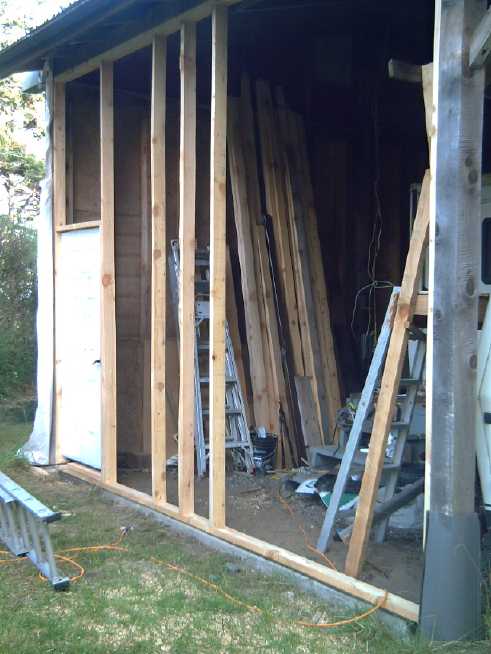
Early in the month I planed some of the 2 by 4s I cut from
the dead spruce in the spring to a uniform 3-13/16 inches wide for wall
studs. I framed the next section; the north
wall, east end of the cabin. I framed around the outside: posts, beams
and concrete footing, then put
in a nice steel door that I got at the refuse station (in excellent
condition except the paint - even that wasn't bad after cleaning), then
studs across, then plywood. Then I took some plywood off.
I stopped because Perry still had his RV in there, which
he has been planning to redo the caulking on for a couple of years
since arriving here. (It leaks.) I should have been urging him on
sooner so I could do these walls while the weather was nice. Ah well,
he started a new business and was very busy, and it's not like I've had
nothing else to do either.
Finally he decided he needed scaffolding to get up there,
so I made him an "A" frame scaffold, with an extension 'fence rail' to
hang onto when standing on the top cross of the "A" making it more a "λ" cross section. And a half step ladder (refuse
station again) screwed on to climb up.
Now that he's working and making good money, instead of
doing it, he's trying to hire someone else to do it. I've given him
until the end of September to finish. I want to get on with the
building and there's a huge garage space he can rent in town if he's
still not done.
I'll have to pull out my own travel trailer too before
doing the fourth wall. I think I'll wait for next spring, since I'm not
going to get to that wall in the next few weeks before cold, wet
weather sets in.
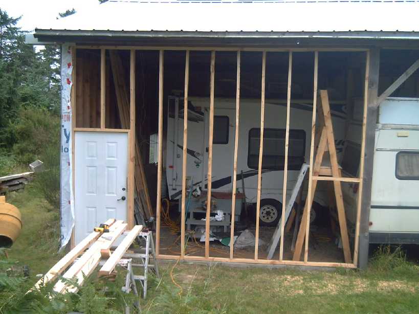 North wall: door, a little window
to look out.
Ground Effect Craft
It seemed to me I had read that currents to the motor
controllers could be up to 115 amps, so it didn't seem unreasonable
that a 100 amp circuit breaker was blowing when I "floored" it. I now
had some breakers rated for
150 amps, and I replaced them with those. [9th] I took the ground
effect craft model to Meyer Lake. I borrowed a kayak from a neighbor in
case I had to go out on the lake to retrieve it. Surely it would take
off now? I put it at the edge of the boat launch ramp and ran it out. I
maneuvered it around a bit. When it was aimed into a clear lane through
the water lilies I gave it the gas. Almost at once the right motor
quit again - this time without blowing the breaker. This time the motor
controller seemed dead - no little tune when it was powered up,
nothing. Battery voltage good, connections good, breaker good. Oh crap!
A little sealed black box. I guess I'll have to order a new one. This
is an unexpected setback. Successful flight seemed imminent. Now it's
far off.
I managed to retrieve the model without the kayak by
wading out into the water and catching it with a 10 foot stick. Just as
well - the neighbor had helped me get the kayak onto the car roof
racks, and when I did take it off by myself later at home I found it
was too heavy for me and I re-injured my weak back for about the third
time since March.
It occurs to me that the one thing I had done since it
seemed to work fine last summer was to lengthen the wires by about 7 or
8 inches to about 2 feet, so the batteries could sit farther back for
better weight distribution. That would increase the inductance and
these very high current things can be really finnicky as I found when
making my own motor controllers. "Every bit of wire is an antenna" as
they say. Could the left one be on the edge of
failure too?
I had meant to get some pictures and video. When I went to
grab my cameras they both needed charging, so I plugged them in and
then forgot to put them in the car. I had my cell phone but it doesn't
go on the tripod and it's so wide angle the craft would have
disappeared into the distance almost before it had taken off. Not that
it took off.
...
I ordered a new 120 amp "ESC" motor controller to replace
the apparently blown one. The store I bought from before seemed to be
gone, and I ordered a different model from a different store. It's good
for 28.8 [nominal] volts so hopefully it will be more robust at 21.6
volts.
At the same time, I saw sets of two joysticks for remote
controls. It occurred to me to make a mounting and attach two side by
side for dual motors throttles - the right way up for intuitive
steering and power to the two motors. And glue or screw them to onto
the left side of the R/C transmitter. Then I would disconnect the
regular left hand potentiometers and wire in the new ones instead. I'm
not totally confident about doing it, but the craft is almost
impossible to steer as it is, and they didn't cost much.
Chevy Sprint Shenanigans (Smaller tire = Performance!)
On the 15th I went to cut an alder log into lumber. I
decided to use the electric Sprint to carry the bandmill and boards
across the acreage. And for that I decided to try using the smaller
diameter "emergency spare" tire on the drive wheel, an idea I had
thought of
last month. It was only 18 inches diameter compared to the 20 inch ones
on the car, giving it a theoretical 11% more torque. Would it just slip
more on the grass? Would the performance difference even be perceptible?
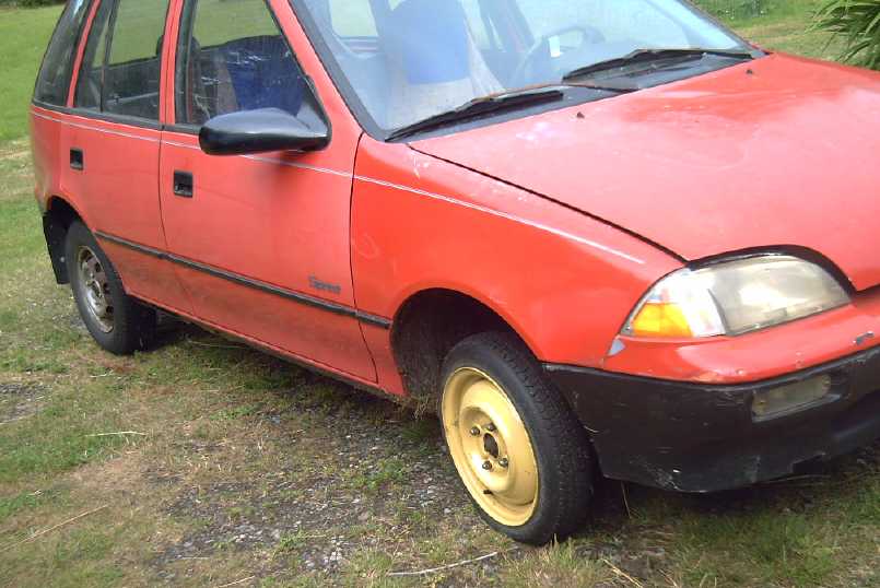 If there was any difference in slipping on the grass, it
seemed it was slightly better. This surprised me. After I had
finished with milling and carting some rocks around, I did some more
driving around without a load.
The best "max. speed" (corrected for tire size) said 25.65
KmPH" instead of just over 20. That indicated better acceleration from
one end of the short field to the other. Climbing the small hill from
the low road back up to the house/shop/garage area usually took
something of a run, or the car would slip and or stall on the way up,
without enough torque to keep going to the top. This time I made it up
from stopped at the bottom! (I expect then it could make it up my steep
driveway from the highway if I dared to try taking it on the road.)
The odometer hit 11 Km - I probably drove 3+ this day. The
next day in the garage I noticed the tire was low. 5 PSI. I put in 40
PSI ("max 60"). It drove about the same.
Who'd have thought that
putting on a 10% smaller diameter
tire could possibly make such a difference? It actually seemed to be
"the" difference between "a bit too feeble" and "just sufficient".
Substantial! And to think, I almost didn't bother to
try it!
I didn't find any promising looking smaller diameter tires
on line. Racing, golf cart or trailer tires, and nothing looked quite
right. (Later I discovered a new car that uses 12 inch tires close
enough to the Sprint's regular size - I was starting to wonder if I'd
be able to get new 12 inch tires at all and the sidewalls are
cracking!) But I got a new idea for a variable torque converter and I
don't think I'll need to bother looking for "low profile" 12 inch car
tires.
Variable Torque Converter - Take 123
This new idea is surely the simplest and potentially the
smoothest and most effective one I have thought of. It combines a
planetary gear and magnetic disks. Two disks replace the special
centrifugal clutch. This time the motor
drives the sun gear (the regular planetary gearset configuration) and
the output rotation to the car wheels is
the planetary assembly (also normal). I picked a 7 to 1 reduction
gearbox and ordered it. All else being equal, the wheels would have a 7
to 1 speed reduction from the motor, which is sufficient for the car to
start moving and accelerate well in most circumstances.
But instead of being held, the ring gear (gearset body) is
free to rotate. If there were no other components the whole body of the
gearset would simply spin freely backward instead of the the car
starting to move forward.
The other part of the equation consists of an alume or
copper disk that spins on the motor shaft, and a disk
of supermagnets positioned next to it attached to the case, the ring
gear. As
the motor starts turning with the car stopped, its alume disk also
turns. Owing to electromagnetic friction, the body/ring gear with the
magnet disk next to it
wants to follow it (forward) instead of spinning freely backward. The
planets assembly then tries to turn forward with 7 times the torque of
the motor at 1/7th of its speed (per normal) while the gearset body
tries to turn backward with 6 times the torque of the motor at 1/6 of
its speed.
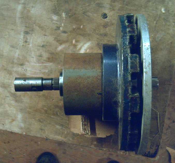 Conceptual mock-up (with a
Planetary gearset I
had handy).
Right: motor shaft with 10" alume disk.
Center: gearset body with 10" magnet rotor attached.
Left: output shaft to wheel via CV shaft.
The motor holds the right end; a steady bearing holds the output end in
alignment.
(The housing that holds the motor at one end and the steady bearing
at the other should be (?)plastic where it passes by the magnets.)
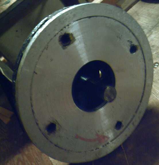 Of course a center will be needed
to hold the
disk to the shaft.
I'll probably use these disks with the Miles mini-cargo truck, which
has a long motor shaft,
and a flat magnet disk for the Sprint car where the space is tight.
Depending then on the motor speed, the strength of the
magnetic interaction at that speed, and the torque needed to move the
car, the body will either turn backward, not move, or turn forward with
the motor. When the strength of the gear force and the magnetism are
equal, the body won't turn either way and the torque to the stopped
wheels is 7 to 1. If the body turns backward, the torque to the wheels
is actually increased. Perhaps it can rise to 10 to 1 or more. (This
should start the car moving even out of a pothole or up a steep hill.)
If the torque needed is less than 7 to 1, the gearbox will begin to
rotate forward in the direction of the motor as the car starts to move.
As the car picks up speed, the slip between motor and body
in "relative RPM" remains constant at a constant acceleration torque.
That means the gear body is spinning faster and faster along with the
motor and the gear reduction is dropping, until as it all speeds up it
gradually approaches 1 to 1 instead of 7 to 1. As acceleration drops
and torque reduces, the slip also reduces, until at zero torque the
reduction ratio is exactly 1 to 1. (Going downhill it will even reverse
during regenerative braking.) At 100 KmPH the gearbox body
(fortunately) is still only turning just under 1000 RPM - slower with
larger tire vehicles.)
Even the mere 2000 max. RPM of the
forklift motor at 1 to 1 reduction theorecticly allows for vehicle
speed headed toward 200 KmPH, along with up to 10(?) to 1 reduction to
start the car moving.
To be determined: the size and magnetic strength of the
disks used. With an estimated maximum 10 to 1 reduction through the
planetary, or something like 7 to 1 from the ring gear, the maximum
magnetic torque required will be correspondingly reduced (if I have it
right either way) to 10% or 14% of the wheel torque. I'm expecting to
be able to use the illustrated prototype 10 inch "electric hubcap"
magnet rotor with that matching alume disk, spinning maybe 1/8 inch
apart. If that's not enough, I have 12 inch rotors, or even (I hope
not!) could use a magnet disk on each side of the alume disk, or even a
copper disk with two magnet disks for ultimate electromagnetic
strength. But I hope not to have to go to such extraordinary lengths.
(Hmm... a bit of late figuring: it might take stronger magnetic forces
than I was thinking. However, I'm going to proceed and find out.)
The housing holding this assembly has to hold the face of the motor,
enclose the disks and the gearset body, and have a steady bearing for
the output shaft, to hold everything in place and in alignment.
I awaited the arrival of the 7 to 1 planetary gearset for
a few days. Then I looked under the truck and saw there was sufficient
room around the shaft to make the "conversion" easy using the same 5 to
1 planetary and shafts it already had, and the two magnetic disks shown
above. The next morning (29th) I pulled the parts out from under the
truck. I found all the other components required to do the job, leaving
a couple of miscellaneous things and a housing to be created to hold
everything.
Since the part of the housing near the magnet rotor is
best made of non-magnetic material, on the last evening of the month I
started thinking of a partly wooden housing, at least for the prototype
on the truck. (I'd prefer welded steel, but it's magnetic. Alume or
copper would make even worse magnetic drag.) Well, surely it can be
made strong enough, and hey!, that makes it even easier to make!
Nothing is proven until it's made and working, but I have
excellent hopes for this and I'll take simply having this new concept
as being fine progress for the month. And now the truck is on "fast
track" for fitting the first prototype. (As much as anything is "fast
track" these days. My new hot water heater took up the afternoon...)
Bandmill Use & an Improvement
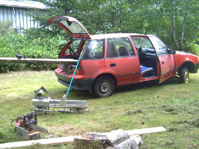
[17th] All-Electric Logging and Milling Operations.
I cut down the trees with the Dolmar electric chainsaw (in March or
April).
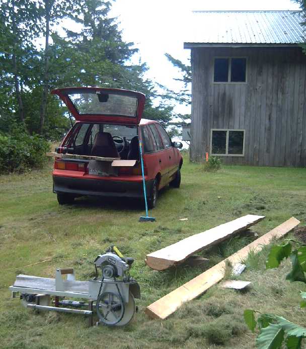 I
milled boards with my electric handheld bandmill (sharp new band this
day).
(Building is neighbor's 'heavy equipment' shop. Orange marker is
property line.
Board on ground is guide board for the mill.)
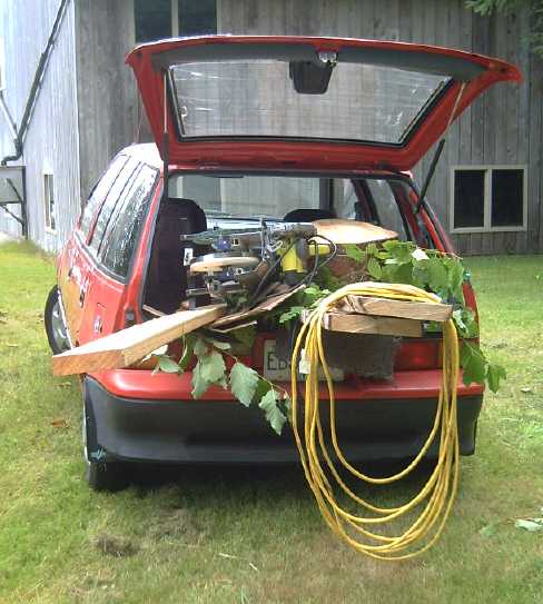 I
hauled the equipment, boards and firewood in the converted Sprint EV.
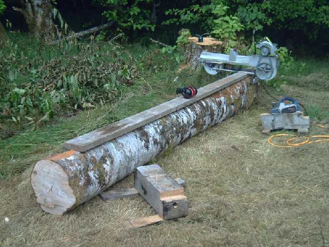 [21st] I started the next
log, a 12 foot piece, at the base 12" x over
16" and 12" x 14" at the top, a considerable piece for a tiny mill.
I have been using an unusual technique for smoothing off
the log: I take off the bumps and high areas with an electric planer
until the guide board sits nicely. (Also if my guide board is a little
too short, as here, when I get near the far end I stop and push the
board until it sticks out sufficiently to hold the saw level as it
comes out the far end of the log.)
I cut 4 slices, on opposite faces, intending to make
boards with cut edges instead of slabs. (Why I thought they wouldn't be
wedge shaped, I don't know!)
The band kept coming
off the drive wheel on the last one. (Why doesn't it track evenly on
both wheels? - must figure this out.) This time however I probably had
the band tension too light. I made an extra effort to tighten it and
finished cutting the slab. It came off again just as it exited the end
and I quit for the day. Maximum cut width was about 11-3/4 inches in a
few spots. (12-1/4 counting the bark.)
So, another revision before it goes commercial: 3/8" band
tracking/tension adjustment bolts. With 1/4" I had to use a wrench on
the wing nuts, and the bolts stripped. The wing nuts on 5/16" bolts are
still too hard to turn by hand to get good band tension. 3/8" wing nuts
should be big enough. or 5/16" knobs. Bolts (carriage bolts?) that
won't turn while adjusting the nuts would also be an improvement, as
would tensioning springs.
A couple of
fat, wide
boards... and a
bench!
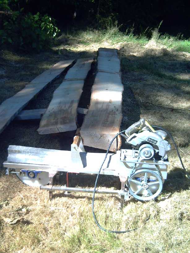 I measured the voltage and power
at the end of the 320 feet of extension cords. It was about 100 volts
when running the mill and 1550 to 1700 watts. (That was with the Cabin
solar panels making 650 watts at the 150 foot mark of the cords, too.)
So I was losing around 20% of the power in the long cords. Not a
surprise! Usually I'm not working so far from the house.
Wayne said he's trying to get approval for his Indonesian
engineer to come to Canada. If he's here, the bandmill is likely to get
a production version and be commercialized. It's not a fast mill, but
it's the only way to cut one or a few logs or cants into lumber with
just a 120V power cord. And easy to stow away when not in use compared
to a mill on tracks. People will love it!
Plastic Recycling 2.0
[27th] In the evening I finally wired the power cord for the oven made
from a freezer.
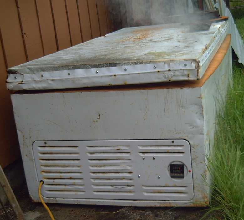 [28th] I put
it all together with much fiddling around. When I finally had it right,
the temperature showed and the heating element came on. At first I just
set it to 50°C. It got up to that fine and cycled rapidly on and
off to keep it right there. Then I turned it to 150°. Around
70° there was a hissing, agitated sound. Ah... water had leaked
into the lid (when I made it if not later) and was boiling off. It
seemed to take a long time going from 98° to 102°, and much
steam was coming out. Eventually it reached 150° and stayed there.
Duty cycle seemed to be around 40%. But it was steaming for over half
an hour. By 45 minutes it had subsided considerably and by an hour it
had stopped. At that point I went to the laundry room and unplugged it.
(What was I thinking not to have put a power switch on it?)
The front (especially) and back had bulged out with the
metal having separated from the insulation at the inside wall. Maybe I
should stuff some fiberglass in there?
Now I'll have to think about a timer to turn everything
"off" after a prescribed length of time so I don't have to sit around
waiting for the plastic to melt properly and then turn it off.
Now I think probably I should put another whole metal skin
with fiberglass insulation inside the inner liner, to keep the hottest
heat entirely away from the foam insulation. It'll still be a plenty
big oven.
Dual EV Boat Motors
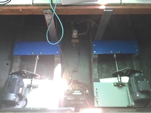 Jim at AGO
Environmental Electronics (Victoria BC) has converted several outboard
boat motors to electric. Now he has installed left and right 230V
induction motors as electric drives on his 26(?) foot Bayliner boat,
with chain drives to the propeller shafts. The gearing to the
propellers can be changed by changing sprocket sizes. "Idler" sprockets
take up the chain slack. He's planning to use an 8,000 watt inverter to
power them from a 48V battery bank. IIRC, 10 horsepower electric is
roughly equivalent to 25 HP gasoline on a boat.
Performance & specs will be derived by testing (which
may not be until spring).
The Wuling Hongguang "Mini EV"
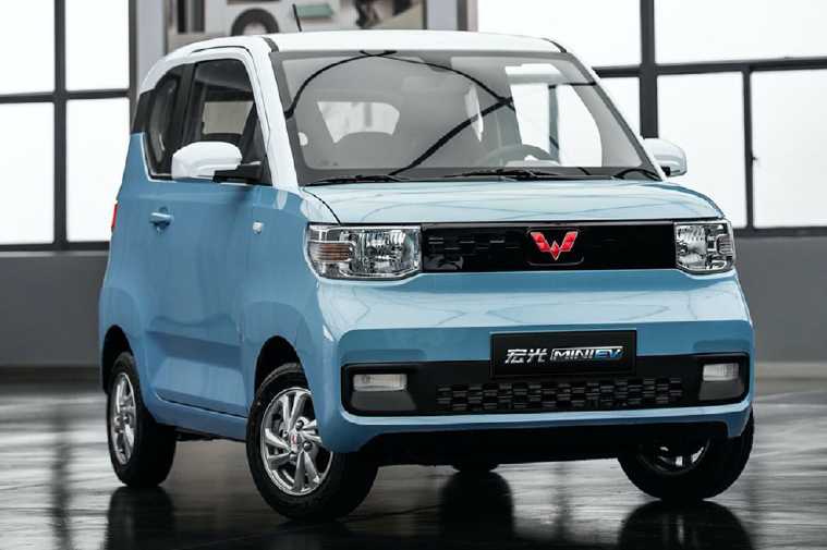 This new electric two-door hatchback from China seems to be attracting
a lot of attention and excitement, and it seemed worthy of
note here for three reasons:
1) It's only around 6000$! (There are two battery options for range and
other 'options')
2) It looked like a pretty decent basic economy car - not "as cheap as
we can make it".
3) It appears one can actually order one from dealers on Alibaba.com
That said, I haven't tried to order one to see if I
actually could, and whether after buying one and getting it shipped
here one could legally license it for the streets in Canada is another
question.
2022 Wuling Hongguang Mini EV: In Depth Walkaround
https://www.youtube.com/watch?v=Vyv1aGfdVrk&ab_channel=JustCARS
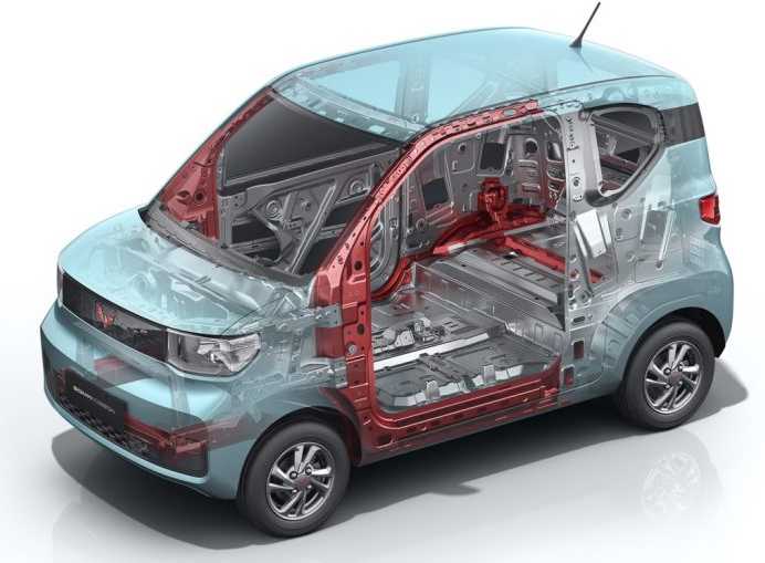 Later I saw it crash tested and disassembled.
The back
seats were dangerous places in the event of a rear end collision. Other
than that, it seemed to be as good (or as poor) as could be expected
for a compact, lightweight car with a very short hood. The front seats
section of the passenger compartment held its integrity in the front
end collision.
In another video a special safety feature stood out: one
was floating level in a flooded street with the driver still inside.
People were laughing at it. A dump truck drove by, wheels mostly
submerged, rocking it with a big wave. Eventually the wheels touched
ground at a side street going up, and it drove up out of the water!
That's impressive. In most cars aside from quitting, it would quickly
sink and you
might drown! You would certainly have to abandon your car.
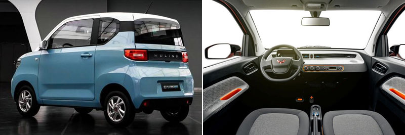 Nothing Fancy, just basic "take
us there"
transportation
Lithium Gripes (Sponsored by Petroleum Industry as usual?)
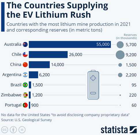 We keep
hearing hear "Oh, lithium mining is done in poor third world countries
where there are no environmental standards and it's an environmental
catastrophe"... and "It's too rare. There won't be enough for all the
EVs people plan to make."
Seems like just another fabrication to justify petroleum
monopoly of transportation to the undiscerning. The chart shows where
lithium comes from. China, perhaps Chile and especially Australia are
hardly "poor third world countries" being exploited by the West.
And here is a new estimate of US reserves:
US Lithium Reserves 750 Gg (gigagrams or 750,000 metric tons - makes
USA's the 5th largest reserves)
And no mention is ever made of the nickel-metal hydride EV
batteries [no lithium] that have been kept off the market for over 20
years by they who have bought all the patents and who refuse to produce
any or allow anyone else to. (All those metal hydride patents must have
expired by now. The main ones did in 2014.)
So the overall message is "Keep using petroleum vehicles
and handing us your hard-earned income, and here's another one of our
twisted excuses why you should!"
Gelled nickel-zinc should be better and cheaper than any
of the above.
Grid-Down Necessities: Well Pump?
To my list of electrical "necessities" for an off-grid
situation - freezer, fridge, lights (,electronics?) - I must add the
well pump, not only for drinking water but for watering the gardens and
greenhouses. When it's warm and sunny out the water needs to be on for
hours at least every second day. Luckily, this is in the summer when
there is lots of sunshine to run the pump, not in December when
there's almost none. But I'd probably want to install that lower power
24V, 300W well pump if there's no mains power.
In
Passing
(Miscellaneous topics, editorial comments & opinionated rants)
Smol
Thots
Big Bust
* Apparently the new James Webb space telescope has just shown the "big
bang" theory of the beginning of the universe to be mistaken. I have
long thought it was a mistaken idea, and there has been evidence
against it for some time.
For example, something as massive a a galaxy yet invisible
has been drawing hydrogen gas away from a young visible galaxy. But
this attractor has no spectral or other data; it emits no light and has
no stars. Only its galactic scale gravity suggests it exists. One
expects that this is ultimatonic/higgs-bosun/adamic particle matter in
process of formation into regular atomic matter from a cloud of energy.
The "big bang" theory does not propose that new matter or energy can be
coming into existence today. If that can happen, the theory is not
needed to explain the existence of energy and matter in the universe.
* People seem highly prone to "explaining" what is not understood as
being caused by some not understandable cataclysmic event rather than
by evolutionary processes. A "big bang" started the universe... an
impossible collision between two planetary bodies broke the moon away
from the Earth (It couldn't possibly have simply formed along with the
Earth?)... there was once a global ice age (before there were extensive
land elevations?!?)... huge lava flows in Siberia killed most life on
Earth - everywhere, land and seas, at the end of the Permian... an
equally impossible asteroid impact killed the dinosaurs. (They weren't
losing ground for millions of years before, and they couldn't have been
outcompeted by the rise of birds and placental mammals?)
Ignoring Symptoms
* The less people know, and the less thought they give to it, the more
they think everything is fine and that the population level is fine and
can keep on growing for the foreseeable future. Some, even some
prominent people, are even concerned that there aren't enough children
being born to keep economies expanding the way they were in previous
recent generations. This is a happy state of mind to be in because one
can carry on with life without becoming depressed or being concerned
about what is happening. Our problems are just beginning.
* Climate change and climate mayhem isn't a problem. Like a fever, it
is a symptom of an underlying problem or problems. Even ignoring the
use of non-renewable fossil fuels we overshot the Earth's sustainable
carrying capacity in the 1960s if not earlier, and we have been in
ecological overshoot ever since. As the population grows, we have used
up the resources (renewable as well as non-renewable) and polluted our
ecology faster and faster with each passing decade. At this point we
are in ecological freefall and our chances to change environmental and
ecological outcomes are mostly "in the rearview mirror". Even if all
human activity could suddenly be stopped now, it is decades too late.
Most of the dire ecological consequences of what we have been doing for
the whole of the "modern" era of civilization are "baked into the
cake". It is too late to do much besides brace for impact.
* In the conditions we have gradually created over the last 150 years
or so, with the number of people that have been created, the question
is not how many billions are going to transit prematurely to the
mansion worlds in the next two or three decades, but how many people
will remain on the planet to rebuild a new and better civilization.
Pessimists speak of half a billion. I think that would entail a new
dark age - a serious loss of human gains of the past few centuries that
would require centuries of regrowth to restore. In accord with others
more reasonable guestimates I would suggest around two billion. And
after all, it is only 98 years since the world first hit two billion
people. The process of depopulating to that sort of figure is a tragedy
for the people involved, a couple of oncoming generations filled with
awful and tragic times and events, but not a tragedy for humanity or
the world as a whole. Three billion is a common upper figure for the
planet's sustainable carrying capacity - once the ecology and
environment have been restored as well as possible in some decades or a
century following the most awful times to come. Although if the sea
level rises enough we may find the land may no longer accommodate a
whole three billion, even for thousands of years.
Mincing Words
* There's a guy on Youtube,
channel "robwords", explaining the origins of things in the English
language and alfabet.
- Eth (Ð, ð) and Thorn (Ϸ, ϸ) are now rare 'Latin' letters used
for
"th" as in "the" (ðe) and in "path" (paϸ). Another,
(Ŋ, ŋ), is for
"ng". (I even derived that lower case shape for myself.) You mean we
actually had proper letters for these phonemes and gave
them up?!? (Haven't seen one for "sh" - ?)
Some renditions of Eth looked too much like Wye (Y). So
you
see a sign "Ye Olde English Inn"? It actually says "The Olde English
Inn".
- Eð and ϸorn are still used
in [at least] Íslands (Iceland).
- After I cast off ðe prejudices of my cultural upbriŋiŋ I ϸought
ðe
American spelliŋs of "humor", "color", "labor" and so on instead of
"humour", "colour" and "labour" were good ideas. What are ðose
extra "u"s for, anyway?
What I didn't know was ðat
Webster in creatiŋ "Ðe American Dictionary" in the 1700s was ðe
one and sole instigator of ðese changes. Ðe power of one!
- And you think the silent letters in "debt", "doubt",
"island" and so on were once pronounced, or have some meaning? Never.
They weren't originally
in the words. They were spelled "det", "dout" and (?)"iland" ("ile"
also in French today). Some (or was it one?) officious middle English
scholar(s) noted that the Latin words for those items (like "debitum"?)
had contained those sounds and figured they should be included in the
English spelling even tho they weren't part of the word. Thanks a lot!
- With "knife" however, the "k" was in the early English sound of the
word, ie, "kneef".
- It seems that in Latin and early French quite a number of words
started with "es". (William the Conquerer brought the early Norman
French to England from Normandy.) So they had something
along the lines of "escule". In many if not most words in English the
"e" was dropped, giving us "scule" or "school". In Parisian French the
"s" was generally dropped and an accent mark added instead, giving
"écule", which came to be
"école". In Spanish many words still start with "es". Latin
"escule" became "escueta". (I have no idea when or where the "h" in
"school" popped in from, but in Russian it's "Шкoлa" ("Shkola"))
- From another source, it would seem the use of "ph" as an "officious"
(IMHO) way of writing "f" was based on (again, one?) medieval scholars'
mispronunciation of "ph" in ancient Greek texts, which it would seem
was just a softer "p". Thus "Phoenicians" was pronounced more like
"Punicians", and the Punic wars against Rome were instigated by the
seafaring Phoenicians (Punicians) that had voyaged to and settled in
Carthage.
- Why is "of" not spelled "uv" or at least "ov"?
ESD
(Eccentric Silliness Department)
* Enquirer: "Can pigs fly?"
Federal agent: "Ya, sure. They're not on the 'no fly' list."
FAA Agent: "Not unless they have a valid pilot's license."
Druggie: "It depends what they're smoking."
* A man broke into a food plant and destroyed the garbanzo beans,
tahini and several other ingredients. He was caught and convicted of
hummuside.
* Trying to keep things ridiculously clean... I think I'flossed my mind!
* Is a 6$ bill twice as phony as a 3$ bill?
* People aren't lazy - they're just "effort challenged".
"in depth reports" for
each project are below. I hope they may be useful to anyone who wants
to get into a similar project, to glean ideas for how something
might be done, as well as things that might have been tried, or just
thought
of and not tried... and even of how not to do something - why
it didn't
work or proved impractical. Sometimes they set out inventive thoughts
almost as they occur - and are the actual organization and elaboration
in writing of those thoughts. They are thus partly a diary and are not
extensively proof-read for literary perfection, consistency,
completeness and elimination of duplications before
publication. I hope they may add to the body of wisdom for other
researchers and developers to help them find more productive paths and
avoid potential pitfalls and dead ends.
Electric
Transport
Some Chevy Sprint Shenanigans (Smaller tire = Performance!)

On the 15th I went to cut the rest of the alder log that
has been
lying at the far side of the acreage for months now into lumber. I
decided to use the electric Sprint to carry the bandmill & tools
across. Then
while I was at it I decided to try using the smaller ("emergency
spare") tire on a 13 inch rim on the drive wheel, an idea I had thought
of last month. (Recap: Only the right front wheel is driven, from
the 36V, 3.5KW forklift motor through a 5 to 1 reduction planetary gear
to the outer half of the original CV shaft: a highly efficient fixed
transmission, but it didn't seem to quite have the torque to climb even
"typical" hills, and it slipped rather easily in the grass.) This tire
was only 18
inches diameter compared to the 20 inch ones on the car, giving it just
a theoretical 11% more torque. Would it just slip more on the grass?
Would the performance difference be perceptible?
As expected, the 13 inch rim, having the same bolt pattern
as the 12
inch rims, fit right on. Room to spare over the brake disk.
If there was any difference in slipping - spinning the
wheel on acceleration and going up hills, it seemed it was slightly better
instead of worse. Perhaps it dug in and gripped better just because it
was so narrow? It had an easier time starting up out of low spots on
the grass. This surprised me. After I had cut a board (and dulled the
saw band badly on a hidden, broken off dead branch with sand around it)
and shortened a
couple of stumps, and carried the equipment, board and some firewood
back to the shop, and some rocks to another location, I did some more
driving around without a load.
I had got it to hit 20 KmPH before, this time the best
"max. speed"
read "28.5" (= 25.65 KmPH allowing for the speedo error with the
smaller tire/wheel). To have got it going faster indicated better
acceleration from one end of the short field to the other. Climbing the
small hill from the low road back up to the house/shop/garage area
usually took a fair run, or the car would slip and stall on the way up,
without enough torque to keep going to the top. This time I took less
of a run at it, and made it fine. Then even less. Finally I started up
the the hill from a stop - and made it up! I imagine then that I could
make it up my steep driveway from the highway if I dared to try taking
it on the road (at least with a run at it).
After all its exertions the motor was for the first time
ever
(AFAIK) quite warm, and parts of the forward-reverse switch hissed if
I touched a wet finger to them. I hadn't connected the current clamp
meter or the Curtis motor controller programmer and I had no voltage
reading. (An indication of state of charge is a poor thing to be
without
in an EV!) Odometer hit 11 Km - I probably drove almost 3
overall this day. (Later I checked the voltage: 38.5V, down from 39.6
or so full charge. 35V would
mean mostly discharged, IIRC, with 32V being the definite "stop
driving!" point.) The next day in the garage I noticed the
tire was low. 5 PSI. (...after sitting in storage for years.) It said
"max 60", but considering the light weight of the car I put in 40. I
drove around once. Seemed about the same.
Who'd have thought that putting on a 10% smaller diameter
tire could
possibly make such a difference? It actually seemed to be "the"
difference between "a bit too feeble" and "sufficient" on typical
hills. Substantially better! And to think, I almost didn't bother to
try it!
I didn't think much of my chances of finding "low profile"
12 inch tires. (Can one even buy any
12 inch rim car tires any more? Were they ever used on any other
vehicles? So, with the sidewall cracks on the present tires, it's good
to know 13 inch rims will fit.) If there are "low profile" 13 inch
tires of 18 or less inches diameter, probably that's what I should put
on the front. If they exist. Otherwise the "emergency spare" is it.
On line the next day, there were some 12 inch tires, but
only one
low profile bias ply racing tire, or trailer tires. Later I found "golf
cart" tires. "Low profile"
didn't seem to be "a thing" with 13 inch tires except for golf carts,
and they seemed to be too wide. I guess that
leaves "trailer tires" (maybe) or "emergency spare" tires. I bet
there's lots of those lying around the wrecking yards! I could put two
on the front to match and
have one in the back for a spare.
Later I saw a new Chinese car (the Wuling HongGuang "Mini
EV", just 6000$!) that had 12 inch tires "close enough" in size to the
Sprint's regular tires and perhaps slightly smaller diameter:
(145/70R12
versus 144/80R12 -- 19.5 inches versus 20 ?).
Later I got another idea, which may eliminate any call
for a smaller tire - see next title.
Variable
Torque
Converter
with
Planetary
Gear:
a Magnetic Method
Ideas evolve faster than
opportunities to build them these days. Sometimes that's a shame. Other
times it's fortunate because a better idea comes along without having
spent time on the first one.
I had thought of using a planetary gear as a variable
torque converter in various ways, and the "car size" low-friction
centrifugal clutch to help effect the "variable" part of it. Or even
just the centrifugal clutch followed by a reduction gear. With a
planetary the whole gear would spin, housing and all, the interaction
between the three elements controlled by the clutch to provide a
variable rate.
I have also realized that the 'variable' part could be
effected by a motor/generator driving or creating drag to control the
rotation of the housing. But that seemed rather complicated.
And I've come up with various "magnetic impulse" variable
converter ideas over the years which never really panned out.
This month I at first thought of having the same
configuration as
with the centrifugal clutch (motor driving planets, ring gear to car,
sun gear to spin) but the sun gear would spin a copper or alume disk
(or drum) instead of the drive plate/shoes of the centrifugal clutch.
Opposite this the ring gear would have a disk (or rim) of strong
magnets. As the motor starts to turn, with the car initially not
wanting to move, the sun gear starts to spin. This puts a drag on the
magnets on the ring gear so the housing wants to follow the disk, and
the disk wants to slow down. The car starts moving. The more torque
needed, the more the slip and the higher the reduction ratio. The less
torque, the less slip.
With (eg) a 5 to 1 reduction planetary, five times the
force on the magnets acts on the output to start the car moving. If it
was 10 to 1, the magnification is ten times. Somewhere in there the
copper and magnet rotors don't have to be absurdly large and powerful
to provide a good leverage, but won't drag the motor down to too low an
RPM. And it would be silent. It wouldn't bee 100% efficient with the
magnetic slip heating the copper, but it should be quite high.
This is right in line with what I've wanted all along, but
once again, it would be another considerable project for just me to
build when I have so many other things, from scratch (while the
centrifugal clutch is already made). I'll have to think about it. (If
only I had thought of it ten or even seven years ago!)
But I have 9, 10 and even 12 inch magnet rotors kicking
around from Electric hubcap prototypes and the improved Piggott
alternator. On the 17th I noticed a 1/2
inch thick alume disk in a storage spot I happened to look in for
something else, about 9-1/2 inches. In case I ever find the time, I
ordered a 7 to 1 planetary gear (hoping that will be about right) so
I'll have all the essential components. (What, I'm spending yet another
500$ that I don't have on something I don't actually need at the
moment?!?)
 [23rd] I had
the thought that the above was probably configuring it the
wrong way, or at least in a poor way. The centrifugal clutch shoes
needed to turn at the highest speed obtainable to get them to engage
strongly. But the magnets interact with a strongly conductive metal at
much
lower speeds, and (as I found with the "magnetic impulse torque
converter" quite a few years back, TE News #47-#50), above a certain
speed there's not additional force to be had. So if instead of the
above, the motor drove the sun gear (right, per normal, with alume disk
attached) and the output to the
wheel was taken from the planets assembly (left, per normal), the ring
gear
(body of the gearset, with the magnet rotor attached) would be the
free-spinning element.
Now we take the 7 to 1 gearset. When the motor starts
turning, the output wants to turn with 7x the force of the motor, at
1/7 the speed. This reduction by itself with the body stopped is enough
for even the 3.5KW forklift motor to start the car rolling under most
circumstances. Therefore we are not asking for more torque than the
motor and gearset would deliver even without any additional parts.
The body wants to turn backward with a force of -6x times
the force of the motor, at similarly -1/6x its
speed. We place the alume disk on the motor shaft and the magnet disk
on the gearset body, with a flux gap between. The gap would be
adjustable by moving the alume disk, to find the optimum coupling gap.
We now have the gears trying to turn the body backward (in
preference to pushing the whole car), but the magnetic coupling trying
to turn it forward. The gears always have the same coupling at any RPM,
but the magnetic coupling increases with the speed difference between
the disks, between motor and gearset body. As the motor speeds up and
the magnetic coupling strengthens, the force trying to slow the body's
reverse rotation down and hence to get the planets assembly to turn
instead (moving the car), increases.
As the speed of the motor and the car increases and the
torque to keep it moving decreases, the ring gear's reverse spin will
slow to zero and then it will start turning in the motor's direction.
As the car accelerates the gearset body will turn more and more along
with the motor.
The more it turns in the same direction as the motor and the wheels,
the lower the reduction ratio becomes until all are moving at almost
the same speed and everything nears 1 to 1 reduction.
One will note that the arrangement has losses because the
magnets and metal disk are always slipping WRT each other, sort of like
the notorious fluid torque converter. I'm not sure how significant the
losses will prove to be. (Hopefully much less!) The prototype should
reveal whether the loss is significant or not.
IF it is, the effect can of course be 'cured' in a number
of ways. One way would simply be to have two or more magnets on the
other disk.
If the torque and relative speed were low enough - just "slippage" -
the two disks would cog magneticly and turn in unison. The best number
of magnets and flux gap could be derived by experiment or perhaps by
calculation. (The motor has to be able to overcome the cogging from a
stop.) But this would make for vibration under higher torque when the
plates aren't cogged. Electromagnets spinning on the metal disk could
be employed to lock the disks together only under the right conditions.
Or an electric brake on the magnet disk with shoes on the metal one
could lock them. (A commutator connection would be required for either)
Another way would be... of course... a special centrifugal clutch
engaged when the assembly is spinning fast enough. (Or perhaps just a
centrifugally actuated cog on the magnet disk that would latch into a
slot on the alume disk?)
The same configuration should work with a
centrifugal clutch instead of magnet + conductive disks, but in 2016 a
motor at 1200(?) RPM didn't seem to engage the shoes of the one I made
very strongly. That's why I had wanted to configure the planetary in
reverse: to make a considerable speed-up to the clutch shoes on the
fast-spinning sun gear.
Truck Too! -- Truck First!
If this works as well as I expect it to, I'll want to
outfit the Miles Mini Cargo Truck with one, too. With the new 7 to 1 on
the Sprint, I could use either of the 5 to 1 gearsets that I already
have. Since there's a 2.2 to 1 (IIR exactly) reduction in the truck's
rear differential, that gives 11 to 1 total reduction to the wheels,
and it only has .45 times the wheel torque acting on the planetary. So
we have plenty of torque to start the truck moving and accelerate well,
and with the planetary fully engaged, a reduction approaching 2.2
to the wheels at highway speeds. The motor controller was programmed to
limit the motor RPM so the speed was only 40 KmPH, with something like
a 4 to 1 total reduction originally. So even without reprogramming the
motor
controller, the truck should attain 73 KmPH. Reprogrammed it could
certainly do 80 or 90 on level pavement and with its 10KW motor
and lightweight batteries probably even up most typical slopes on the
highway.
So once again perhaps it's well I didn't get around to
working further on the truck's transmission yet, since this totally
changes it.
Perhaps it's worth noting that while the planetaries one
orders on line are quite long end to end, they could easily be made
only a couple of inches thick, with the alume magnetic disk adding just
a bit more. Along with axial flux "pancake" motors, it should be pretty
easy to fit two motors and variable torque converters, one for each
wheel, rather than using one motor with a differential gear, for
ultimate efficiency. And there's extra reliability: if one motor quits,
the other can still drive you to a repair shop.
[28th] If I used the same (5:1) planetary all connected the same way as
presently, the conversion should be simple. I figured there wouldn't be
room for the rotors, but I looked under the truck, and there was! That
would be the simple first one to make then. I would have to put the
steady bearing on the original drive shaft to the rear wheels, which
had a "machine smooth" 32mm section at the front. So I had the
planetary, the magnet rotor and the alume rotor. Only a 32mm bearing
was lacking. Hmm... perhaps the steady bearing could be mounted on the
body of the gearset instead of the output shaft? (I found I had a 35mm
cup and cone ("trailer wheel") bearing... that might just work?) Why do
they make most motor and gearset shafts so * short?
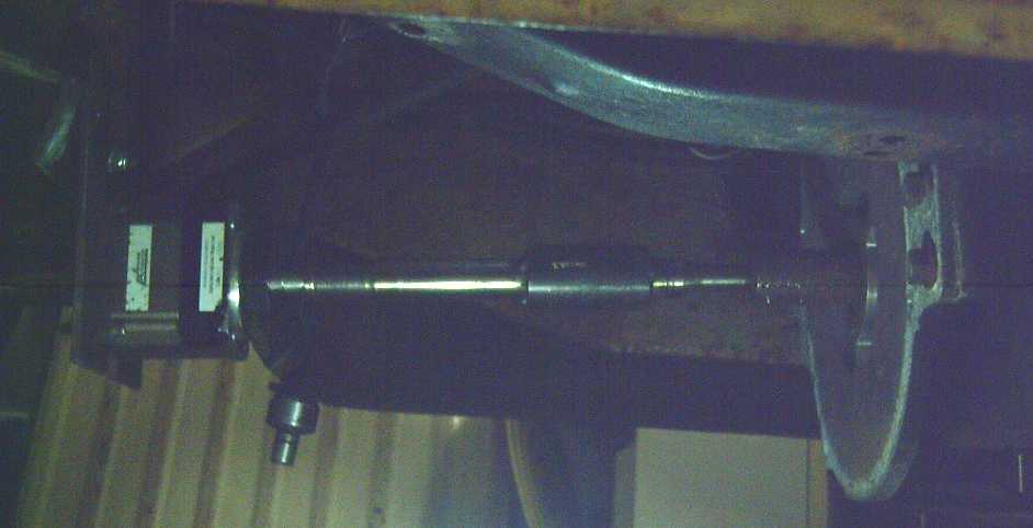 (Apologies for the lighting!)
Drive train under the truck.
The magnetic disks would be just right of the planetary on the left,
which would no longer be bolted to a plate to the truck frame but
"free" (except magneticly) to spin.
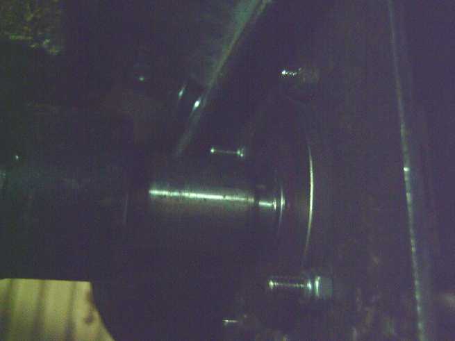 Output end - truck's drive shaft.
The mounting
plate will
need to attach to a steady bearing on that short output shaft.
The steps then would be:
1. Make a center to fit the alume disk to the 19mm(?) shaft from the
motor. If it can slide up and down the shaft, the magnetic gap can
easily be adjusted without disassembly.
2. Attach the magnet disk to the body of the planetary. I think all it
needs are 4 bolt holes.
3. Fit a steady bearing to the output shaft. (or to the output end of
the body?)
4. Make a case/housing of some sort to tie the motor to the output of
the planetary (the steady bearing) to hold everything rigid and in a
straight line. It would also attach the steady bearing end to the truck
frame.
Each of these tasks will be something of a challenge, but they should
all be doable. I should probably order a 32mm roller bearing ASAP.
Suddenly it went from "I should get around to getting the
truck running again sometime" to an exciting, cutting edge R & D
project with huge potential!
[29th] In the morning I pulled the shaft and planetary out of the truck.
1. The shaft near the planetary was one inch, and I found a 1" SDS hub
and a giant washer I could use to attach it to the alume disk.
2. Four holes in the magnet rotor lined up with with the four #10-32
threaded holes on the input side of the planetary gear. Little pipes
for spacers around the bolts will ensure it stays centered. (Seems like
pretty small bolts to me, but it's the lower torque side and it'll only
turn up to around 1200 RPM.)
3.Much to my surprise I found a needle bearing that fit on the
planetary's output shaft, and a flange for it to hold the stationary
part to the housing.
Not bad for a morning's work! That left fiddling around with those, and
of course the hard part - the housing. There was an alume flange on the
face of the motor with three holes, not quite at 120° to each
other. There were the mounting holes for attaching that end.
Later, thinking about magnetic drag on the magnet rotor, I
thought of making some of the housing from wood. Hmm... That could
speed construction up some more! finally I'm wondering if the whole
thing might need considerably more magnetic interaction than I've been
thinking... double rotors, bigger diameter, copper instead of alume for
more conductivity. Well, I guess I'll find out!
Axial Flux EV Motors Discussion
(from Youtube Video Comments)
& putting Brakes Inside Car Idea
I watched a video about some new axial flux EV motors. The
presenter thought they were going to be "game changers". It sounded
like they had some features in common with mine (did they get ideas
from TE News?), but technical details weren't the focus of the video.
More interesting were some of the many comments under the video, some
seemingly quite knowledgeable. I copied some of the more interesting
and enlightening ones. Since they were published and were intended to
enlighten people, I'll feel free to re-post them here. Of course, it is
gratifying to see some that reinforced my own views on the subjects as
well as broadening them.
Axial flux motors are great and might fit in a car wheel
hub, but I (after some experiments) and others have tended to frown on
in-wheel motors because they add to un-sprung weight. My old Tercel
felt something like a truck when I had mounted extra weight on the
wheel and axle. I would rather put the motors inside the hood and
connect them with single-joint CV shafts, as I have done with the
Sprint (TE News #168, 169). Short axial flux motors should be good for
this because two might be fitted within a car's width. The
forklift radial flux motor extends well over into the other side of the
car.
Someone had an interesting idea: there is already
considerable un-sprung weight in a wheel in the brake components,
notably the brake drum or disk. If that disk can be replaced by a
magnet rotor disk that weighs little or no more, the weight of the hub
motor is offset to a degree. If the magnets are on one side and the
reverse remains smooth, brake cylinders and pads can be placed front
and rear on the smooth side. Of course much of the braking will be
regenerative by electromagnetic force, but the vehicle still needs to
come to a complete stop and 'lock' there mechanicly. And the stator
with iron cores and copper coils adds more weight than just the
magnet rotor.
But then I looked at it the idea other way around: if the
each
motor connects to its wheel via an outer-joint end of a CV shaft, the
entire
brake
assembly
can
also be at the inner end of the shaft, inside the vehicle
or under the hood, and will be
sprung weight instead of un-sprung. This would reduce the
un-sprung weight considerably. For example while most cars are heavier
all around than the Sprint, we might attempt to guestimate for its
wheel:
Brake Disk: 8 pounds? (Nissan Leaf's is 10 pounds)
Brake piston assembly with brake pads: 4 pounds?
Other parts holding the wheel on the car (axle, unsprung portions,
incl. cut CV shaft): 12 pounds?
Typical 12 inch wheel with tire: 20 pounds (I weighed one. Again I
remember the Tercel's (13 inch) as being about 25 pounds)
Total unsprung weight: 44 pounds.
If one eliminated the brake components:
Total unsprung weight: 32 pounds.
A 25%-30% percentage reduction of wheel weight would make
for more nimble handling cars! Indeed, it might be almost in a class of
its own, and it would be a great selling feature. The idea does assume
that the CV shaft and bearings can take the force of hard braking -
even of skidding the wheels on dry pavement. That might mean increasing
the thickness and weight of the CV shaft - shall we add 2 pounds and
(counting half as 'unsprung') make it 33 instead of 44?
An additional benefit is that the brakes would be inside
rather than exposed to the grime and salt from the road, kicked up by
the wheels. They would last far longer with a correspondingly
reduced maintenance cost.
There might - just possibly - be yet one more benefit: if wheel rims
don't have to be designed to fit over a brake disk or drum, the design
might be improved. Their weight might be lightened (yet more weight
reduction) or they might (somehow) provide less rolling resistance.
* * * * *
Well, here's some of the actual comments from under the video, below.
https://www.youtube.com/watch?v=SyqBQhKsoP8&ab_channel=TheElectricViking
I found them more interesting than the video itself.
Paul
Axial flux motors are a big deal, yes. Not a total game changer, but a
significant improvement nevertheless. And yes, there were around before
the radial flux motor we all know, being the first electric motors
invented. Nicola Tesla actually had a patent on a version he designed.
All thin CD players use axial flux motor because the radial does not
fit in that tight of a space. Some elevator use large ones, for
example, due to their higher torque and efficiency. Their issue has
been that the machinery for mass manufacturing hasn't been there
because radial are easier to design for simple applications like
ceiling fans and power tools, and other similar applications, the main
uses of electric motors until now. After the mass manufacturing is in
place, the issue remaining is heat dissipation. Especially in the
yokeless design.
This was
something I found. The Electric hubcap motor in the Sprint in 2015-2016
heated up surprisingly fast under heavy load at low RPMs. And the
Electric Caik in the outboard didn't dissipate heat well. It took a
while, but it just kept getting warmer.
As far as efficiency, they are absolutely more efficient than radial
because their power/electric mechanism is stationary being axial as
opposed to radial because by design they use alternating current to
induce the rotation, therefore use a little less electricity/power to
do the same job. Their efficiency is obviously not more than 100%,
that's idiotic to even mention, however, they do reach above 96% on
average. So they are at least 6 to 7% more efficient than radial, while
still having 30 to 35% more torque. And they can be much smaller, so
much so that, yes, Ford actually tried using them inside the tire's
rims for the Mach-E and Lightning, but their efforts obviously failed
due to the fact that you mentioned -- there is no suspension there to
take the shocks of the road. Perhaps in the future tiny suspension
designs that fit inside the rim can allow it. But for now, that's out
of the question.
In spite of
never having done proper tests and getting hard figures, I was finding
that the last version of the Electric hubcap motors seemed to require
almost nothing to keep them going with no load, and seemed still quite
efficient under heavy load (notwithstanding heating up). I was
estimating they were about 95% peak efficiency and people didn't seem
to believe me. (It was quite a contrast to the very first version that
was only around 50% efficiency.) Now we see "above 96%" as an average
peak efficiency, which makes my claim modest.
They are so efficient and light that Rolls Royce is using them for
their electric airplane motors they are working on now. In fact, they
are actually currently testing them on actual small airplanes. So yes,
axial flux motors will absolutely enter the EV world soon. <snip>
John Boen
Thoughts on efficiency... from a class I took on windings motors...
Typical motors operate better in one direction ... they also have to
operate like a generator, meaning they have to absorb power. The design
for maximum output efficiency makes generator efficiency pretty
low.
There is a certain amount of tuning to turn an efficient motor into an
efficient generator.
But these are highly symmetric - they should work equally well as
motors and generators.
It could be recovering 2x as much energy as older designs.
If they are 2/3 the weight... if they are smaller... if they produce
less heat... and they recover 2x as much energy...
Hidden
benefits not immediately obvious from the printed specs!
Mike l
Denis T / Yes, but you forget one important thing: higher torque coming
from an electric motor, in any physical package smaller or bigger of
the electric motor, comes with higher necessary amps meaning higher
current consumption.
Torque formula for electric motors is like this:
Torque ( N-m ) = 9.5 X Power ( KW ) / Speed ( RPM )
Or practically : Tq= 9.5 X UI / RPM
Do you see that multiplication of the 2 terms UI? Those are U=voltage
and I=current.
To have more torque you can use higher voltage, higher Amps or both.
At the same voltage, more Torque means more Amps.
And don't forget that more Amps means higher temperature.
All OK, now?
I hadn't seen
this formula and constant before. Cool!
Bill Gaytes
I was working with Axial flux (pancake motors) in the 70's and they
were around long before then. The biggest disadvantage is there is no
thermal inertia so when you dump a huge amount of current into them
(torque) they get hot very quickly as they don't have a big armature
mass to soak up the heat.
Once again,
the rapid heating issue that I was having with the Electric Hubcap
motor.
Chris G
Axial flux motors are a way of squeezing more out of given energy
inputs. That is the case primarily because axial flux motors are
lighter than their radial flux cousins and because energy losses to
rotational impediments are reduced. Taken together those two factors
mean that torque and power density (which are measured relative to
motor weight) can go up a lot even as the efficiency rating of the
motor only increases by a modest amount.
I suspect there might also be a degree of difficulty in calculating
motor efficiency precisely or in an indisputable fashion. Year after
year more efficient radial flux motors are making their way to
production. These new motors have consistently improved on the current
state of the art in electric motor design. I am not sure that
calculated efficiency always fully reflects the degree to which these
motors have improved.
It is worth noting that not all electric motors are based on magnetic
drive principles. So how does one rate the efficiency of a motor based
on electrostatics against magnetic motors? It seems to me everything
must finally reduce to some distance output/charge input calculation
(with certain test conditions, e.g. driving conditions and vehicle
weight, controlled/equalised) but short of that the technical factors
playing a leading role in motor design mightn't look alike (across
different motor types) and could even generate pictures of motor
efficiency that aren't easily commensurable.
Sam, you would be doing those who follow your vlog a great service if
you set about trying to answer some of the questions you have raised.
Of course, a dyno will tell us a lot about the performance
characteristics of a motor but that doesn't mean motor design is based
on what the dyno tells us - ideally, the dyno will confirm the motor
designers assumptions about how best to design a motor. Also, it would
be nice to know whether motor designers work with highly generalisable
accounts of efficiency or whether their work requires them to look at
things in a unique way more applicable to the type of motor that they
are developing.
Well, there
are certainly some of the finer details to take into account! Of
course, two motors might both boast "88% peak efficiency", but graphs
of efficiency under varying loads and varying RPMs might look quite
different for each motor. Someone (youtube somewhere) took a 1000W
bicycle hub motor, and then a tiny 1000W model airplane motor, and said
"Why can't I gear the airplane motor down and use it as a bicycle
motor?" He tried it. The model airplane motor indeed ran the bicycle,
but it got smoking hot quickly. Same watts figure, but they were rated
quite differently. And in the bicycle application there was no
propeller blowing cold air onto the motor - an unspoken condition that
would simply be "assumed" for aircraft models.
Edward De Jong
@IncognitoTorpedo theoretically, if you can make the hub
motors light enough, that will be a superior arrangement, as the
knuckles and universal joints cost you in various ways. When you have
very powerful motors those shafts are non-trivial in weight and
inertia. I have no doubt in my mind that eventually some company
will ship hub motors. [clipped]
This is the
comment that got me thinking about where the motors and brakes are. If
a CV shaft is straight, there should be no losses. The more it bends at
the joint, the higher the losses will be. So for non-hub motor
efficiency it's a question of being able to position the components so
the shafts are pretty straight unless the car is turning.
zmavrick
To understand axial flux motors requires a completely different
mindset. There are different types of electrical motors that work very
differently and we are used to trying to understand them by comparing
them to ICE engines and that doesn't work. I have been building these
motors and generators as a home hobbyist for years and they are very
efficient, especially for RPM's less than 2,200. Above that you
get field latency problems in the the cores which causes heat buildup.
The easiest way to think of their method of operation is that instead
of current driven the current is used for field switching.
This isn't a revolutionary game changer, but it does open
up some real possibilities for system performance efficiencies. At a
time when battery materials supply is having problems keeping up with
demand increases this is important. Even a slight performance increase
could result in a slight reduction in batteries required. Multiplied by
thousands of cars this could have a significant reduction in overall
batteries needed. Reductions in weight of both the drive train and
battery pack could also give a significant improvement on tire wear.
Here the new
variable torque converter will come into play. It keeps the motor RPMs
low even on the highway, so that a 95% peak efficiency BLDC axial flux
motor is always operating in its most efficient speed range. This
eliminates the value of high speed reluctance motors unless they can be
as efficient on the road as the BLDC-torque converter combo. (In which
case, being cheaper is an advantage.) "My money" is on the BLDC with
variable torque converter - which one expects (also favorable comment
somewhere above) is also better at regenerative braking.
Other "Green" & Electric Equipment Projects
Plastic Recycling 2.0
[27th] In the evening I finally
wired the power cord for the oven made from a freezer. Sounds simple
enough... the delay was partly from indecision. It only needed a 15 amp
breaker as the heating element was only about 9 amps. One could do that
9 amps with a simple #16 AWG extension cord instead of the heavy wire I
had run to the stove. But this being North America, the power outlets
are all 120V, not 240. Should I put the heavy "dryer" plug on the end
of a light power cord, and run it through the window into the laundry
as I had done with the original oven? Or, use a 15A, 240V plug and plug
it into the water pump supply? But if I used a 15A plug and plugged it
into the water pump supply, I would surely forget and run the water
pressure down to nothing and get air in the lines and hot water tank.
Or should I do some house wiring and add a proper new 240V, 15A socket?
I finally went with the path of least resistance and connected the
light extension cord to the bulky "dryer" plug via an in-line
electrical box.
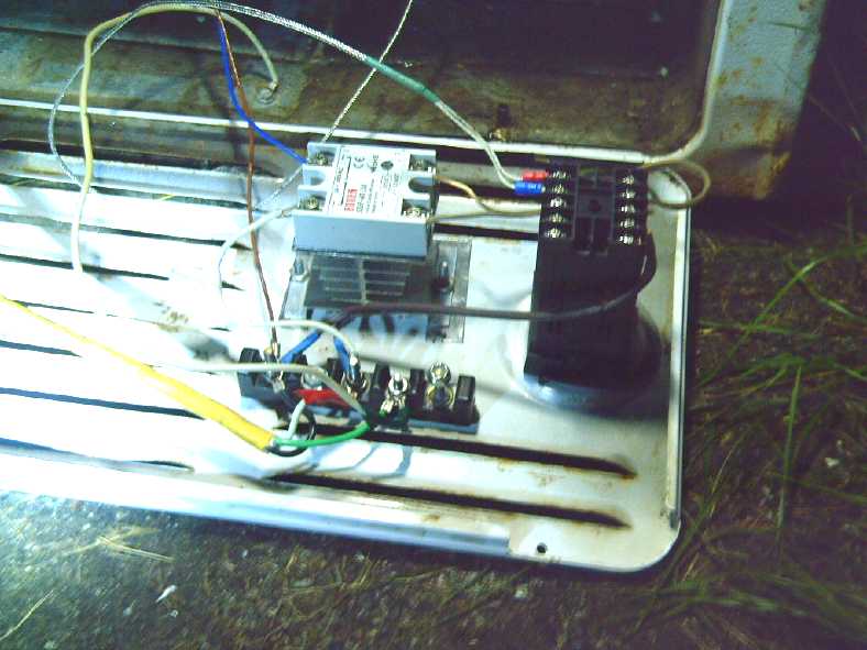 [28th] I put it all
together with much fiddling around. I got the confusing temperature
sensor wiring wrong several times and it kept flashing "error". (Which
was which? Is TC the 'temperature compensation' or the 'thermo
couple'?) I finally went to youtube and looked at a video. Hey, it
doesn't even need that second "temperature compensation" thermocouple
(that wasn't supplied)! Some versions of the controller don't even have
the third terminal to connect one. That simplified things!
 When I had it
right, the temperature showed up instead of a blinking error code and a
clicking alarm relay. And the heating element came on. At first I just
set it to 50°C. It got up to that fine and cycled rapidly on and
off to keep it there.
Then I turned it to 150°. Around 70° there was a
hissing, agitated sound. Ah... water had leaked in (when I made it if
not later) and was boiling off. It seemed to take a long time going
from 98° to 102°, and much steam was coming out. Eventually it
reached 150° and stayed there. Duty cycle seemed to be around 40%.
But it was steaming for over half an hour. By 45 minutes it had died
down and by an hour it had stopped. At that point I went to the laundry
room and unplugged it.
(What was I thinking not to have put a power switch in?)
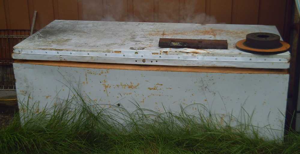 The front
(especially) and back had bulged out with the metal having separated
from the insulation at the inside wall. I was worried that might happen
at plastic melting temperatures, not at 150°. Obviously the foam
insulation is inadequate.
In a comment under a video
someone mentioned that solid state relays usually fail "on", and that
that would leave your heating element on. I'm not sure having the
element left "on" will raise the temperature much higher than that
desired anyway. It may depend on whether I can seal the door well or
not. I'll have to think about it, and about a timer to turn everything
"off" after a prescribed length of time so I don't have to sit around
waiting for it.
Now I think probably I should put another whole metal skin
with fiberglass insulation inside the inner liner, to keep the hottest
heat entirely away from the foam insulation. Or maybe if I heat it up
and the foam gets soft or melts, I can unplug the heating element and
pull the whole inner liner right out? (Nothing else holds it in?) Then
it might be simple to replace the insulation with fiberglass or rock
wool?
Gardening
Sunflowers!
 3 in the south wall garden were
the most
successful: 2 'giant', 1 'dwarf'.
 28th - The 'dwarf' always looked
somewhat
pathetic with ever-drooping leaves,
but it grew a 10 inch head in July that matured near the end of August.
The 'petals' on each seed (left half) could be easily brushed away
(right half).
I picked it after this picture and took it in to dry. The weather
turned rainy.
 28th - The largest of the 'giant'
ones grew a
head about 14 inches across, but rather late.
The seeds weren't ripe and in general the little 'petals' on each seed
weren't ready to drop off.
 31st - The 'petals' were easier
to brush off
the seeds, but they
still need some warm weather to ripen. 50-50 whether they get it.
It would seem the 'dwarf' are more the reliable variety to grow around
here.
This year, for the first time I had planted sunflowers in
trays indoors in the spring. For some reason I had always thought of
them as "flowers" rather than a food plant, notwithstanding all the
sunflower seeds I've eaten in my time. And I wasn't sure they'd grow
here. But I planted a couple in the garden last
year. It was too late for them to produce, but they grew very tall. It
finally dawned on me that they're a good source of food. Since I bought
an oil extractor (for something else; aliexpress.com), if I grow enough
I could even make sunflower oil.
There were a tall and a short variety whose names
escape me. ("Fordhook Giant"? Or is that swiss chard?) I planted three
in the garden at the south wall of the
house. The one surviving short one made a huge flower during July
filling out with
ripening seeds by mid August, and the tall ones followed 2 or 3 weeks
later. Three in the greenhouse apparently wanted more light and by mid
month were pressing on the ceiling instead of flowering. One in the
main garden that
survived the slugs was finally flowering by mid August. I think I'll
just grow the short variety against the house wall next year. "Early"
has a better chance of success here, especially if it's not a nice
summer. (I seem
to have lost the seed package with the name, but I can grow them from
the plant's own seeds.) Near the end of the month, the huge ones
finally started maturing too. The day the weather started to turn cold
and rainy (28th) I picked the 'dwarf' flower (about 10 inches diameter)
and brought it in to dry the seeds. The large ones (one over a foot
diameter) look great but they need another week or two of warm sunshine
that they're probably not going to get.
Luckily I don't think the little forest squirrels
around here know what they are, so there's a great chance of good
annual sunflower crops. ...with the earlier 'dwarf' ones.
Sheep? Goats? Geese? ...or benefits thereof?
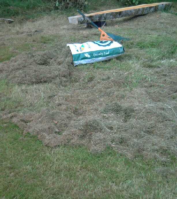 [25th] I had
been harvesting lawn grass cuttings for wall insulation
all summer (R3+ per inch), but finally I was sure I had enough at least
for the two walls I might finish this year (65+ bags). And I had some
extra feed bags. I had cut some very tall grass around the logs I was
milling after they were moved, and there was such a matt of cut grass
on top as to kill the living grass underneath. Now it occurred to me
that if I didn't want to keep sheep or goats myself, I might sell or
trade bags of feed hay to people who did, so they could feed more
animals through the winter, perhaps for milk or meat. That gave me a
new reason to collect the grass, and I stuffed the 10 bags. Then I took
two bags to people 'nearby' (5Km) with goats and geese to see what they
thought of the
idea. They seemed receptive to it. But the weather turned wet. Summer,
evidently, was over and I probably couldn't do any more dry grass.
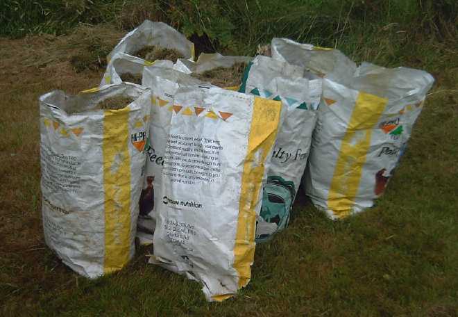 No hay baler, but I had a rake
and lots of bags.
Corn
 Greenhouse, August 17th. Spindly
looking corn...
and a great big volunteer cabbage (bottom)!
An older cabbage making tasty seeds, far right wall
 [29th] I finally plucked a
cob from the spindly looking corn in the greenhouse. When I opened it I
was very pleasantly surprised. Okay, it's nothing much, but it was the
best looking cob I've grown here. Carefully hand pollinating must have
paid off. I cooked it right away. It was delicious: sweet, tender,
fresh! (If only I didn't suspect it was also the best one of only a few
in the whole greenhouse.) Maybe next year I'll go back to making a
knee-high "cold frame" and keeping the corn under cover until it's too
tall (hopefully warm by then), then letting it grow in full sunlight.
And careful hand pollinating. By the south wall of the house. Along
with everything else that grows best by the south wall of the house.
Blueberries
 I first bought
two blueberry bushes in 2017 when I moved here, at the Tlell "Fall
Fair" (Early August if not end of July). The next one in 2018 I bought
two more. Finally I planted them by the house in 2019. One died, but
with lots of water they seem to do well, and I got a pretty decent
little crop in 2020 and 2021. By 2021 I bought a couple more, and this
year (2022) yet another two, which I planted in the main garden.
This year I seemed to get a small handful of berries every
day or two for much of the month, and I started freezing them. I had
635 grams (plus whatever I had eaten) at the end of the month and there
were still some yet to ripen. Many if not most of the berries came from
the
two oldest plants, notwithstanding a ladder blowing over and breaking
off a large branch from the biggest bush in the spring.
Lupins
 For about the
third time, I tried growing a few lupins this year. no special reason.
Perhaps I was inspired by "Denis Moore, the Lupin Bandit"? This time I
put them by the south wall and the slugs didn't get them while they
were small. One between two sunflowers made a nice flower stalk, and
another had finally started just at the end of the month.
An interesting side note is that when the Norse colonized
Iceland, they cut down trees... and discovered that in Iceland's poor
soil, high latitude and climate, they grew back extremely slowly. In
fact, windstorms blew away the little sod there was and Iceland became
a desert with barren ground. And so it has remained for centuries.
Then someone who went to Alaska brought back Alaskan lupin
seeds. (in the 1940s?) Lupins are nitrogen fixing and they are covering
the bare ground and making it purple, spreading a few more feet each
year. (Is it an invasive species if there were essentially no species
there before?) And holding the soil and making it fertile again. As
things progress other plants are able to take root and eventually there
will be variety and doubtless even forests again. (IIRC they were
having some success with aspen or poplar.)
(Perhaps "Alaskan" lupins would be a better variety for me to grow
here? Alaska is not far to the north of here.)
Of course there's lots more
I could write about: peas (another good crop), beans, a couple of fine
cabbages, carrots (Finally some decent carrots!) and surely potatoes.
But these are the things that stood out as exciting or at noteworthy to
me this month.
Electricity
Storage
Gelled Nickel-Zinc Batteries
[Dang, no report! I have the PVA, why
can't I get to this?]
Electricity
Generation
My Solar Power System
The Usual Daily/Monthly/Yearly Log of Solar
Power Generated [and grid power consumed]
(All times are in PST: clock 48 minutes ahead of local sun time, not
PDT which
is an hour and 48 minutes ahead. (DC) battery system power output
readings are reset to zero
daily (often just for LED lights, occasionally used with other loads:
Chevy Sprint electric car, inverters in power outages or other 36V
loads), while the
grid tied readings are cumulative.)
Daily Figures
Notes: House Main meter (6 digits) accumulates. DC meter now
accumulates until it loses precision (9.999 WH => 0010 KWH), then is
reset. House East and Cabin meters (4
digits) are reset to 0 when they get near 99.99 (which goes to "100.0")
- owing to loss of second decimal precision.
New Order of Daily Solar Readings (Beginning May 2022):
Date House, House, House, Cabin => Total KWH Solar [Notable
power
Usages; Grid power meter@time] Sky/weather conditions
Main
DC East
(new)
Km = Nissan Leaf electric car drove distance, then car was charged.
July
31st 3644.35, 6.67, 30.30, 26.60 => 15.06 [75Km; 98249@21:00] Light
clouds, bit of sun.
August
01st 3649.85, 6.75, 34.12, 29.79 => 12.59 [98264@20:30] Clouds.
02d 3657.48, 6.87, 39.53, 34.41 => 17.78 [55Km; 98295@21:00]
Clouds, some sun in PM.
03rd 3662.15, 7.30, 43.10, 37.37 => 11.63 [55Km; 98324@20:30]
Clouds.
Rain. (Sigh!)
04th 3666.57, 7.44, 46.40, 40.09 => 10.58 [98348@20:30] Mor cloudz,
rain. (Needed the rain!)
05th 3674.14, 7.53, 52.58, 45.13 => 18.88 [90Km; 98379@20:30] Cloudy
AM, Sunny PM.
06th 3683.87, 7.59, 60.17, 51.92 => 24.17 [55Km; 98404@20:30] Mostly
sunny!
07th 3688.33, 7.67, 64.15, 55.25 => 10.85 [98415@21:00] Occasional
sunny moments.
08th 3697.76, 8.12, 72.20, 61.97 => 24.65 [55Km; 98426@20:30] Sunny
day!
09th 3708.76, 8.19, 80.43, 69.66 => 26.99 [98439@21:00; 65Km]
Beautiful day, ~25°
10th 3719.31, 8.27, 88.43, 77.21 => 26.18 [98455@20:30] Gorgeous,
even Hot, 27.5° in shade (my thermometer)
11th 3727.98, 8.33, 95.75, 83.42 => 22.26 [90Km; 98473@20:00]
Overcast earlier AM, then sunny again. (Clouds again near sunset.)
12th 3730.34, 8.39, 2.46, 85.56 => 7.02
[98487@20:00] Overcast.
13th 3735.43, 8.46, 6.09, 88.78 => 12.01 [55Km; 98504@20:00]
Mostly overcast. Cooler.
14th 3742.77, 8.54, 11.61, 93.42 => 17.58 [50Km; 98520@20:30] Light
overcast w. sunny periods.
15th 3751.02, 8.64, 17.60, 98.43 => 19.45 [98530@20:00] No real sun.
16th 3753.62, 8.71, 19.44, 1.52 => 6.05 [98542@20:30]
Lots of rain overnight. Clouds, fog, wind, brr.
17th 3759.95, 9.34, 25.39, 6.37 => 17.76 [20Km; 98553@20:00]
AM cloudy, PM sunny.
18th 3769.92, 9.70, 33.01, 13.62 => 25.20 [55Km; 3 laundry;
98573@20:30] Sunny & Warm! ("Too hot!" says Kamil.)
19th 3780.31, 9.83, 40.71, 20.88 => 25.48 [98580@20:30] Sunny &
Warm again!
20th 3790.49, 9.90, 48.41, 28.03 => 25.10 [98592@20:30] Another fine
day!
21th 3796.18, 9.96, 51.89, 31.37 => 12.57 [98605@20:00] Sunny AM,
then clouds.
22th 3804.97,10.03,58.89, 37.45 => 21.94 [90Km; 98625@20:00] Fair
bit of sun.
23th 3812.32, 0.08, 64.61, 42.46 => 18.16 [98634@20:00] Still some
sun.
24th 3822.16, 0.14, 72.01, 49.11 => 23.95 [98648@20:00] Sunnee todae!
25th 3828.93, 0.21, 77.30, 53.29 => 16.31 [98659@20:00]
26th 3833.61, 0.27, 80.98, 56.23 => 11.36 [98670@20:00] Clouds,
Rain, later jet trails
27th 3836.42, 0.37, 82.75, 57.74 => 6.19 [95Km;
98702@20:00] Clouds, drizzle.
28th 3838.86, 0.50, 84.32, 59.05 => 5.45 [98722@20:00]
Looks like summer is over.
29th 3840.86, 0.62, 85.53, 60.08 => 4.36 [98756@19:30]
30th 3844.72, 0.77, 88.15, 62.37 => 8.92 [98792@20:00]
Not quite so dulll.
31st 3849.92, 0.84, 92.43, 65.64 => 12.82 [98810@20:00] A bit of
summer still?
September
1st 3857.43, 0.93, 97.87, 70.25 => 17.65 [60Km; 98836@20:30] Some
sun, not cold.
Chart of daily KWH from solar panels.
(Compare AUGUST 2022
(left) with July 2022 & with August 2021 - but note number of solar
panels differs.)
Days of
__ KWH
|
August 2022
(18 solar panels)
|
July 2022
(18 sol. panels)
|
August 2021
(12 solar panels)
|
0.xx
|
|
|
|
1.xx
|
|
|
|
2.xx
|
|
|
1
|
3.xx
|
|
|
|
4.xx
|
1
|
|
|
5.xx
|
1
|
|
5
|
6.xx
|
2
|
1
|
5
|
7.xx
|
1
|
2
|
1
|
8.xx
|
1
|
3
|
2
|
9.xx
|
|
|
6
|
10.xx
|
2
|
|
3
|
11.xx
|
2
|
2
|
2
|
12.xx
|
4
|
2
|
1
|
13.xx
|
|
2
|
|
14.xx
|
|
1
|
3
|
15.xx
|
|
1
|
2
|
16.xx
|
1
|
4
|
|
17.xx
|
3
|
|
|
18.xx
|
2
|
2
|
<= chart ended here until April 2022!
|
19.xx
|
1
|
|
<= |
20.xx
|
|
|
<= ...improved wiring in April
|
21.xx
|
1
|
2
|
|
22.xx
|
1
|
|
|
23.xx
|
1
|
1
|
|
24.xx
|
2
|
2
|
|
25.xx
|
3
|
1
|
|
26.xx
|
2
|
|
|
27.xx
|
|
4
|
<= In May 2022 just 3 new panels...
|
28.xx
|
|
|
<= @ sunniest place (carport roof)...
|
29.xx
|
|
1
|
<= brought it way up here!
|
30.xx
|
|
|
<=
|
31.xx
|
|
|
<=
|
Total KWH
for month
|
505.12
|
519.37
|
284.47
|
Km Driven
on Electricity
|
1054.5 Km
(~145 KWH?)
|
1192.3 Km
(~165 KWH?)
|
1187 Km
(~165 KWH)
|
Things Noted - August 2022
* In mid month the nearby tree shadows started covering the panels on
the lawn in late morning. By the end they passed through the garden by
the house. This is of course every year, and it is notable in the
figures for 2020 and 2022 where the house (& lawn) panels drop more
than the cabin (& carport) panels that don't enter into that shade.
(In 2019 a new panel was added on the lawn, bringing the figure up for
August. I'm not sure why 2021 seemed different.)
Monthly Summaries: Solar Generated KWH [& Power used from
grid KWH]
Month: House system (+ DC system at house) + Cabin system = KWH made
[used from grid]
2019
March 1-31: 116.19 + ------ + 105.93 = 222.12 KWH - solar [786 KWH
used from
grid] (10 solar panels
total)
April - 1-30: 136.87 + ------ + 121.97 = 258.84 KWH [608 KWH]
May - 1-31: 156.23 + ------ + 147.47 = 303.70 KWH [543 KWH] (11th
solar panel connected on lawn on 26th)
June - 1-30: 146.63 + 15.65 + 115.26 = 277.54 KWH [374 KWH] (36V, 250W
Hot Water Heater installed on 7th)
July - 1-31: 134.06 + 19.06 + 120.86 = 273.98 KWH [342 KWH]
August 1-31:127.47 + 11.44+91.82+(8/10)*96.29 = 307.76 KWH [334 KWH]
(12th solar panel connected
on lawn Aug.
1)
Sept.- 1-30: 110.72 + 15.30 + 84.91 = 210.93 KWH [408 KWH]
(solar includes 2/10 of 96.29)
Oct. - 1-31: 55.67 + 13.03 + 51.82 = 120.52 KWH, solar
[635 KWH used from grid]
Nov. - 1-30: 36.51 + 6.31 + 26.29 = 69.11
KWH, solar [653 KWH used from grid]
Dec. - 1-23: 18.98 + .84* + 11.70 =
31.52
KWH, solar + wind [711 KWH + 414 (while away) = 1125 from grid]
2020
Jan. - 6-31: 17.52 + ------* + 10.61 = 28.13 KWH,
solar+
wind [1111 KWH from grid]
Feb. - 1-29: 56.83 + ------* + 35.17 = 92.00 KWH,
solar + wind [963 KWH from grid]
* The solar DC system was running the kitchen hot water
tank. Now it's only running a couple of
lights - not (usually) worth reporting. So there's just the 2 grid tie
systems:
house and "roof over travel trailer" (AKA "Cabin").
One year of solar!
March - 1-31: 111.31 + 87.05 = 198.37 KWH solar total
[934 KWH from grid]
April - 1-30: 156.09 + 115.12 = 271.21 [784 KWH
from grid]
May - 1-31: 181.97 + 131.21 = 313.18 KWH
Solar [723 KWH from grid]
June - 1-30: 164.04 + 119.81 = 283.82 KWH Solar [455 KWH
from grid]
July - 1-31: 190.13 + 110.05 = 300.18 KWH Solar [340
KWH from grid]
August- 1-31: 121.81 + 83.62 = 205.43 KWH Solar [385KWH
from Grid]
Sept. - 1-30: 110.68 + 65.09 = 175.77 KWH Solar [564
KWH used from grid]
Oct. - 1-31: 67.28 + 42.55 = 109.83
KWH Solar [1360 KWH from grid -- Renters!]
Nov. - 1-30: 35.70 + 20.79 = 56.49
KWH of Solar [1301 KWH from grid]
Dec. - 1-31: 19.78 + 11.31 = 31.09
KWH Solar [1078 KWH used from grid]
2021
Jan. - 1-31: 25.47 + 18.58 = 44.05
KWH Solar [1185 KWH used from grid] (1
solar panel moved to DC system only -- 11 panels)
Feb. - 1-28: 47.18 + 33.22 = 80.40
KWH Solar [1121 KWH used from grid]
Two years of solar!
March - 1-31: 81.73 + 55.22 + 2.2 (DC) = 139.15 KWH
Solar
[1039 KWH grid]
April - 1-30: 161.83 + 112.35 + .44(DC) = 274.62 KWH
Solar
[680 KWH from grid]
May - 1-31: 156.25 + 97.22 + 1.29(DC) = 254.76
KWH
Solar [678 KWH from grid]
June - 1-30: 197.84 + 112.07 + 2.21(DC) = 312.12 KWH Solar
[& 448 KWH from grid] (Connected
12th
solar panel -- 13 panels total but one goes
to DC system only.)
July - 1-31: 204.35 + 121.21 + 4.06(DC) = 329.62 KWH
Solar [426 KWH from grid; 150(?) KWH used by Nissan Leaf]
August- 1-31: 176.19 + 102.91 + 5.37(DC) = 284.47 KWH Solar [477 KWH
from grid; 165 KWH (est) used by car]
Sept. - 1-30: 94.35 + 51.34 + 3.30(DC) =
152.29 KWH Solar [590 KWH from grid; 155 KWH (est) used by car]
Oct. - 1-31: 77.52 + 41.85 +
4.10(DC) = 123.47 KWH Solar [1066 KWH from grid; 150 KWH (est) used by
car] (2 new panels on pole
making 14 --
but they are mostly in shadows all winter.)
Nov. - 1-31: 34.69 + 18.92 + 3.82 = 57.43
KWH Solar [1474 KWH from grid (ouch!); 140 (est) used by car]
Dec. - 1-31: 24.00 + 5.22 + 3.76 = 32.98 [1589 KWH from grid (ouch
again! Must be the -10°'s); 120 KWH used by car] (New switches allow switching
some panels
between AC and DC as needed, so all 15 are productively employed.)
2022
Jan. - 1-31: 32.83 + 20.54 + 4.57 = 57.94 KWH Solar [2556 from
grid] Double ouch! Trailer 400W heater, Perry's RV 500W heater, bedroom
heat, car using extra power (100 KWH with less driving)... and so
little
sun!
Feb. - 1-28: 66.63 + 32.09 + 3.42(DC) = 102.14 KWH Solar [1118
KWH from grid; 130 (est) used by car]
Three years of solar!
March - 1-31: 128.53 + 82.29 + 3.66(DC) = 214.48 [1124 KWH from grid;
160 KWH (est) used by car]
April - 1-30: 251.29 + 149.87 + 3.01(DC) = 404.17 KWH Solar
[911
KWH; est. 170 KWH used by car]
May - 1-31: 255.01(house)+6.46(DC)+140.46(carport)+145.91(cabin)=547.74
KWH Solar [933 KWH from grid;
140 KWH (est) used by car; Bitcoin miner using extra power from 22nd
on.] (3 new solar panels
on carport roof
-- sunniest location around -- total 18)
June - 1-30: 234.54 + 2.10 + 160.70 + 139.18 = 536.52 KWH
[from grid: 864 KWH - dang bitcoin miner!]
July - 1-31: 232.12 + 4.57 + 143.03 + 139.65 = 519.37
KWH Solar [from power grid: 710 KWH; 165 KWH (est) used by car]
August-1-31: 205.57 + 4.20 + 157.88 + 137.47 = 505.32 KWH Solar [from
grid: 561 KWH; 145 KWH (est) used by car]
Annual Totals
1. March 2019-Feb. 2020: 2196.15 KWH Solar [used 7927 KWH
from
grid]
2. March 2020-Feb. 2021: 2069.82 KWH Solar [used 11294 KWH from grid]
(More electric heat - BR, Trailer & Perry's RV)
3. March 2021-Feb. 2022: 2063.05 KWH Solar [used 10977 KWH from grid]
Money Saved or Earned - @ 12¢ [All BC residential elec.
rate] ; @
50¢ [2018 cost of diesel fuel to BC Hydro] ; @ 1$ per KWH [total
cost to BC Hydro
in 2022 according to an employee]:
1. 263.42$ ; 1097.58$ ; 2196.15$
2. 248.38$ ; 1034.91$ ; 2069.82$
3. 247.57$ ; 1031.53$ ; 2063.05$
It can be seen that the benefit to the society as a whole
on Haida Gwaii from solar power installations is much greater than the
cost savings to the individual user of electricity, thanks to the heavy
subsidization of our power
owing to the BC government policy of having the same power rate across
the entire province regardless of the cost of production. And it can be
insurance: With some
extra equipment and a battery, solar can deliver essential power in
electrical outages however long.
https://www.TurquoiseEnergy.com
Haida Gwaii, BC Canada

 Cabin
Construction
 If there was any difference in slipping on the grass, it
seemed it was slightly better. This surprised me. After I had
finished with milling and carting some rocks around, I did some more
driving around without a load.


 [21st] I started the next
log, a 12 foot piece, at the base 12" x over
16" and 12" x 14" at the top, a considerable piece for a tiny mill.
 I measured the voltage and power
at the end of the 320 feet of extension cords. It was about 100 volts
when running the mill and 1550 to 1700 watts. (That was with the Cabin
solar panels making 650 watts at the 150 foot mark of the cords, too.)
So I was losing around 20% of the power in the long cords. Not a
surprise! Usually I'm not working so far from the house.
 [28th] I put
it all together with much fiddling around. When I finally had it right,
the temperature showed and the heating element came on. At first I just
set it to 50°C. It got up to that fine and cycled rapidly on and
off to keep it right there. Then I turned it to 150°. Around
70° there was a hissing, agitated sound. Ah... water had leaked
into the lid (when I made it if not later) and was boiling off. It
seemed to take a long time going from 98° to 102°, and much
steam was coming out. Eventually it reached 150° and stayed there.
Duty cycle seemed to be around 40%. But it was steaming for over half
an hour. By 45 minutes it had subsided considerably and by an hour it
had stopped. At that point I went to the laundry room and unplugged it.
(What was I thinking not to have put a power switch on it?)
 Jim at AGO
Environmental Electronics (Victoria BC) has converted several outboard
boat motors to electric. Now he has installed left and right 230V
induction motors as electric drives on his 26(?) foot Bayliner boat,
with chain drives to the propeller shafts. The gearing to the
propellers can be changed by changing sprocket sizes. "Idler" sprockets
take up the chain slack. He's planning to use an 8,000 watt inverter to
power them from a 48V battery bank. IIRC, 10 horsepower electric is
roughly equivalent to 25 HP gasoline on a boat.
 This new electric two-door hatchback from China seems to be attracting
a lot of attention and excitement, and it seemed worthy of
note here for three reasons:
 Later I saw it crash tested and disassembled.
The back
seats were dangerous places in the event of a rear end collision. Other
than that, it seemed to be as good (or as poor) as could be expected
for a compact, lightweight car with a very short hood. The front seats
section of the passenger compartment held its integrity in the front
end collision.
 We keep
hearing hear "Oh, lithium mining is done in poor third world countries
where there are no environmental standards and it's an environmental
catastrophe"... and "It's too rare. There won't be enough for all the
EVs people plan to make."
 [23rd] I had
the thought that the above was probably configuring it the
wrong way, or at least in a poor way. The centrifugal clutch shoes
needed to turn at the highest speed obtainable to get them to engage
strongly. But the magnets interact with a strongly conductive metal at
much
lower speeds, and (as I found with the "magnetic impulse torque
converter" quite a few years back, TE News #47-#50), above a certain
speed there's not additional force to be had. So if instead of the
above, the motor drove the sun gear (right, per normal, with alume disk
attached) and the output to the
wheel was taken from the planets assembly (left, per normal), the ring
gear
(body of the gearset, with the magnet rotor attached) would be the
free-spinning element.

 [28th] I put it all
together with much fiddling around. I got the confusing temperature
sensor wiring wrong several times and it kept flashing "error". (Which
was which? Is TC the 'temperature compensation' or the 'thermo
couple'?) I finally went to youtube and looked at a video. Hey, it
doesn't even need that second "temperature compensation" thermocouple
(that wasn't supplied)! Some versions of the controller don't even have
the third terminal to connect one. That simplified things!
 When I had it
right, the temperature showed up instead of a blinking error code and a
clicking alarm relay. And the heating element came on. At first I just
set it to 50°C. It got up to that fine and cycled rapidly on and
off to keep it there.
 The front
(especially) and back had bulged out with the metal having separated
from the insulation at the inside wall. I was worried that might happen
at plastic melting temperatures, not at 150°. Obviously the foam
insulation is inadequate.


 [25th] I had
been harvesting lawn grass cuttings for wall insulation
all summer (R3+ per inch), but finally I was sure I had enough at least
for the two walls I might finish this year (65+ bags). And I had some
extra feed bags. I had cut some very tall grass around the logs I was
milling after they were moved, and there was such a matt of cut grass
on top as to kill the living grass underneath. Now it occurred to me
that if I didn't want to keep sheep or goats myself, I might sell or
trade bags of feed hay to people who did, so they could feed more
animals through the winter, perhaps for milk or meat. That gave me a
new reason to collect the grass, and I stuffed the 10 bags. Then I took
two bags to people 'nearby' (5Km) with goats and geese to see what they
thought of the
idea. They seemed receptive to it. But the weather turned wet. Summer,
evidently, was over and I probably couldn't do any more dry grass.

 [29th] I finally plucked a
cob from the spindly looking corn in the greenhouse. When I opened it I
was very pleasantly surprised. Okay, it's nothing much, but it was the
best looking cob I've grown here. Carefully hand pollinating must have
paid off. I cooked it right away. It was delicious: sweet, tender,
fresh! (If only I didn't suspect it was also the best one of only a few
in the whole greenhouse.) Maybe next year I'll go back to making a
knee-high "cold frame" and keeping the corn under cover until it's too
tall (hopefully warm by then), then letting it grow in full sunlight.
And careful hand pollinating. By the south wall of the house. Along
with everything else that grows best by the south wall of the house.
 I first bought
two blueberry bushes in 2017 when I moved here, at the Tlell "Fall
Fair" (Early August if not end of July). The next one in 2018 I bought
two more. Finally I planted them by the house in 2019. One died, but
with lots of water they seem to do well, and I got a pretty decent
little crop in 2020 and 2021. By 2021 I bought a couple more, and this
year (2022) yet another two, which I planted in the main garden.
 For about the
third time, I tried growing a few lupins this year. no special reason.
Perhaps I was inspired by "Denis Moore, the Lupin Bandit"? This time I
put them by the south wall and the slugs didn't get them while they
were small. One between two sunflowers made a nice flower stalk, and
another had finally started just at the end of the month.