Turquoise Energy News Report #174
Covering
November
2022 (Posted December 5th 2022)
Lawnhill BC Canada - by Craig Carmichael
(CraigXC at Post dot com)
www.TurquoiseEnergy.com
= www.ElectricCaik.com
= www.ElectricHubcap.com
Month In "Brief"
(Project Summaries etc.)
- I Want a Better Camera? - Improving a Peltier Cooler: "New"
Experiments - New Battery Experiments
- Magnetic Variable
Torque
Converter: Better than The Best! (making for Miles Truck) - Axial
Flux
Unipolar BLDC Motor (5KW? - Magnet rotor cut)
In
Passing
(Miscellaneous topics, editorial comments & opinionated rants)
- Amazon: A Den of Thieves! -
Car Key FOB Hidden Health Hazard - Smol Thots - ESD
- Detailed
Project Reports
-
Electric
Transport - Electric Hubcap Motor Systems
* Magnetic Variable Torque Converter with Planetary Gear: The
Future of the Automotive Industry! (Building one for Miles Truck)
* Axial Flux Unipolar BLDC Motor - 5KW? - Magnet Rotor
Other "Green"
& Electric Equipment Projects
* Peltier Cooler Performance: Greatest Cooling is running at
9-10 volts
* Indoor & LED Gardening
Electricity Storage:
Batteries
* Gelled Ni-Zn Salt Cell - A.K.O. New Experiment Details
Electricity Generation
* My Solar Power System:
- The Usual Latest Daily/Monthly
Solar Production log et cetera - Monthly/Annual Summaries,
Estimates, Notes
On the afternoon of December 5th, I was walking toward
home on the left shoulder of the highway, having found that the upper
beach was very rocky today and it was near high tide. There was very
little traffic. A vehicle came up from behind, slowed, and the
Purlolator van stopped beside me. "I have a box for you." Through the
driver's window he handed me a box that said "Westlab" - my KCl salt!
"Thanks!" "Only on Haida Gwaii, eh?" he said and continued on his way.
I Want a Better Camera?
I had been trying to get a better camera. In my earliest
wave power tests (2008) the wind had blown over my 2005 Centrios
DVD/camera on a tripod and about 1/3 of the display's LCD liquid leaked
out,
leaving the already tiny display barely showing what I'm taking a
picture of, much less whether it's blurred or out of focus. A button
clicks to 'near', 'portrait' and 'far'. If it was wrong, too bad. For
close-ups I have to try at about 9, 10 and 11 inches and use the best
one. My old cell
phone had been good but the 'new' one doesn't focus close up. I bought
a
camera on AliExpress that likewise disappointed me. Somebody gave me
one from a thrift shop that took good pictures but the display was
still too
small for my liking and worse, I couldn't find a cable with its odd
plug to
connect it to
USB. Somebody told me to try "Best Buy". Just before I went on
line I looked at my 7 year old RCA Android 'tablet with keyboard' that
I
never use. Hmm, it has two cameras. I removed the keyboard, powered it
up and discovered that it seemed to take focused close-ups! And the
screen is of
course huge to view the scene and the result. Problem solved? (If only
its internal lithium battery lasted longer, or it took regular "AAA"
cells that could be swapped! If you leave it a week without plugging it
in, it's dead. Unless you turn it right off, after which it takes a
coon's age to boot.)
Sigh! When I went to use the first set of pictures I had
taken with the tablet, I found that they weren't nearly as sharp and
clear as from my
2005 camera, to the point where I couldn't compare 'before' and 'after'
images of an electrode that might reveal changes, one from
each camera. Back to square one! Or maybe my old camera isn't so bad
after all? Hmm. Or maybe I should try Best Buy after all?
 Quality images?
Improving a Peltier Cooler: "New" Experiments
 Perry gave me
a Peltier module camping cooler he found at
the thrift store. It didn't seem to work. I checked the module by
itself and it cooled. After some frustrating sessions trying to figure
out what was
wrong, I reversed the polarity of the fan motor, which spun both the
outside and the inside fan at opposite ends of the same shaft. It
cooled!
Someone had wired the fan and the module oppositely. (The odd-shape
blades seemed to be right, but they just didn't work that way
around.)
Perry gave me
a Peltier module camping cooler he found at
the thrift store. It didn't seem to work. I checked the module by
itself and it cooled. After some frustrating sessions trying to figure
out what was
wrong, I reversed the polarity of the fan motor, which spun both the
outside and the inside fan at opposite ends of the same shaft. It
cooled!
Someone had wired the fan and the module oppositely. (The odd-shape
blades seemed to be right, but they just didn't work that way
around.)
From looking at graphs on Peltier module datasheets long
ago, I had noticed
that the COP (Coefficient of Performance) was better and better (a) the
less the temperature spread was between the hot and cold sides of the
module and (b) the lower the current drive. The current drive is
reduced by reducing the voltage. That provides less wattage of actual
cooling, but the cooling losses from heating of the hot side are
greatly reduced.
 From those
specs I have long thought that "12
volt"
Peltier modules (unless trying to attain the most extreme temperature
drop) would cool much more efficiently at a lower voltage.
With a "properly" working cooler now, I could give the theory a good
test. I ran it off a DC to DC converter from the 36VDC solar power
system and turned the adjustment pot to various output voltages over
the day. The table
shows the results. At the nominal rated 12 volts it used 45 watts and
got the
cooler down to about 11°C cooler than the room. Much as I had
surmised, at 7 volts it used 1/3 the power (15W) to provide
approximately the
same temperature drop! Peak cooling effect seemed to be attained at
about 9-10 volts and 25-30 watts power draw.
From those
specs I have long thought that "12
volt"
Peltier modules (unless trying to attain the most extreme temperature
drop) would cool much more efficiently at a lower voltage.
With a "properly" working cooler now, I could give the theory a good
test. I ran it off a DC to DC converter from the 36VDC solar power
system and turned the adjustment pot to various output voltages over
the day. The table
shows the results. At the nominal rated 12 volts it used 45 watts and
got the
cooler down to about 11°C cooler than the room. Much as I had
surmised, at 7 volts it used 1/3 the power (15W) to provide
approximately the
same temperature drop! Peak cooling effect seemed to be attained at
about 9-10 volts and 25-30 watts power draw.
If you're trying to run it off your car battery overnight,
15 or 20 watts is much better than 45! Running off a solar panel only
in the
daytime, 25 or 30 watts provides the maximum cooling to keep the cooler
coolest. I'd call a cheap DC to DC converter to
reduce the voltage an excellent asset for running a Peltier
camping
cooler! I'm surprised makers of both Peltier modules and camping
coolers haven't caught on. A Peltier rated for about 18V instead of 12V
would
cool better with less power at 12 volts. (Extra
details under Other "Green" & Electric Equipment Projects.)
There was snow on the ground the day I did these tests. I
won't be camping any time soon.
Cooler
Supply
(Volts)
|
Power to
Cooler
(Watts)
|
Cooler
Temperature
Drop (~°C)
|
13
|
53
|
11.7
|
12
|
45
|
11
|
11
|
39
|
11
|
10
|
30
|
12.5
|
9
|
25
|
12.4
|
8
|
20
|
11.7
|
7
|
15
|
11
|
6.5
|
13
|
10
|
The other improvement to Peltier performance is to
minimize the temperature difference between the hot and the cold faces.
Among other things, both faces should contact with the best possible
heat conductor to reduce the temperature loss/gain in the junctions.
This would mean using silver, copper or at least pure alume in
the heatsinks. This seems to never be done. Alume alloy is fine
for keeping transistors from roasting, but it's not
as good a heat conductor as pure alume and has higher thermal
resistance at those
critical junctions. Pure copper is even better. Reducing the heat
loss/gain in both junctions by just
one degree would mean the same cooler could cool by 14.5° instead
of 12.5°. (Maybe I should try my "superinsulated Peltier chest
fridge" again with copper on the hot side as well as the cold side? It
certainly seemed to perform better than most Peltier coolers even with
just the one fat copper bar, on the cold side. It froze water in the
ice tray.)
(Hint for Peltier cooler camping: cool the food in a regular fridge or
freezer, maybe throw in a block of ice, before you leave. The cooler
will take a long time to get food cool, expecially at low watts.)
New Battery Experiments
I finally got back into these experiments with some crappy
weather when I didn't want to do any outside work. I improved my
techniques and learned a lot about things I've been "stuck" on for
ages. I think am much closer to making good cells.
Key findings:
1. The nickel-manganates powder electrodes work and repeatedly
recharge. (It should have at least twice the energy per kilogram of the
beta
nickel oxyhydroxide presently used in typical rechargable alkaline
cells.)
2. The nano-powders from that electrode penetrate separator papers and
make a low resistance path across the cell, slowly deteriorating the
performance. This seems to be cured simply by
wetting the paper with Varsol first. (it must close or reduce larger
pores?)
3. Other than that, my perennial self-discharge problems are evidently
caused by soluble impurities which have to be diluted out in baths of
water or electrolyte.
4. Including that the "99.9% KCl" electrolyte salt itself seems to be
contaminated. Solved by drying out a salt solution and collecting the
purest crystals off the sides of the tray.
5. Cupro-nickel current collectors seem to work in the positive
electrode. (better than graphite sheets.)
6. Improved cell constructions.
I must say that
doing battery chemistry experiments has been worse than watching paint
dry. It occupies much time. I suspect
some of the things I've been trying haven't been tried before simply
because people have run out of patience for ideas with markedly
uncertain outcomes. Especially salt electrolyte rechargeable battery
chemistry and
techniques don't seem to have been very well explored. Everybody jumped
on the KOH alkaline electrolyte bandwagon when Jungner found that
nickel (and only nickel) didn't corrode in the plus electrode, while
graphite/carbon was the only thing so far found to work in salt, and it
limited currents and cell forms. (And now, with zinc still not properly
tamed and the low effective watts per gram energy of beta nickel
oxyhydroxide, 'everyone' has jumped on the lithium bandwagon.)
Perry imported a 6 foot arborite/melamine countertop with
a backsplash for me from Home Depot on the mainland, something I've
wanted for ages
to set on top of my washer and dryer and short sink counter - at last,
a decent work surface
at standing height, that won't stain and can be wiped clean, for my
very meager "chem lab"!
Externally
Clamped Cell,
under charge. L: mA; R:
V
 With the
externally clamped cell(s) system I found I could use a sheet of rubber
for the front face of the cell and not glue it. This was
revolutionary in my experiments as I could now seal and reopen the cell
any time. I can replace each any any component as desired. (Why didn't
I have anything like this, if not in 2008, at least by 2012 or 2013?
Duh!)
With the
externally clamped cell(s) system I found I could use a sheet of rubber
for the front face of the cell and not glue it. This was
revolutionary in my experiments as I could now seal and reopen the cell
any time. I can replace each any any component as desired. (Why didn't
I have anything like this, if not in 2008, at least by 2012 or 2013?
Duh!)
 I also finally
got tired of having a dozen alligator clip test and voltmeter probe
leeds all falling off or making poor connections, and wired a bunch of
connections to a terminal block to reduce their number. If it looks
cluttered, it has nothing on just a pile of loose wires.
I also finally
got tired of having a dozen alligator clip test and voltmeter probe
leeds all falling off or making poor connections, and wired a bunch of
connections to a terminal block to reduce their number. If it looks
cluttered, it has nothing on just a pile of loose wires.
As of
this writing I it appears my cells have been performing poorly because
of a combination of small things:
 * Traces of soluble
materials in the electrode powders, which then dissolve in the
electrolyte. Especially nitrate ions will travel back and forth
becoming nitrate at one electrode and nitrite at the other, stealing
the electrons from the one and releasing them into the other to make a
continual self discharge. The solution seemed to be to bathe the
materials or electrode in water about 3 times before using them and
then drain the water, to dissolve and dilute out soluble impurities
beforehand.
* Traces of soluble
materials in the electrode powders, which then dissolve in the
electrolyte. Especially nitrate ions will travel back and forth
becoming nitrate at one electrode and nitrite at the other, stealing
the electrons from the one and releasing them into the other to make a
continual self discharge. The solution seemed to be to bathe the
materials or electrode in water about 3 times before using them and
then drain the water, to dissolve and dilute out soluble impurities
beforehand.
 * Likewise, impure KCl electrolyte salt has
probably been causing self discharge. My "99.9% KCl" salt from a health
food store needs to be purified by dissolving it and evaporating the
water. It seems the salt that crystallizes on the side of the beaker as
the water evaporates is pretty pure, the impurities settling out last
at the bottom. Some I made (tried to make?) by combining KOH (USP
grade) and suspect purity HCl had a thick dark gray sludge on the
bottom. Yikes! (Some KCl I ordered from Westlab hasn't come yet.)
* Likewise, impure KCl electrolyte salt has
probably been causing self discharge. My "99.9% KCl" salt from a health
food store needs to be purified by dissolving it and evaporating the
water. It seems the salt that crystallizes on the side of the beaker as
the water evaporates is pretty pure, the impurities settling out last
at the bottom. Some I made (tried to make?) by combining KOH (USP
grade) and suspect purity HCl had a thick dark gray sludge on the
bottom. Yikes! (Some KCl I ordered from Westlab hasn't come yet.)
* Air needs to be kept out of the cell.
Oxygen gas will oxidize (discharge) the salty, wet zinc electrode. (And
carbon dioxide may gradually turn things irreversibly into carbonates.)
Leaks need to be sealed.
* The nano-powders of the positive electrode seemed to be seeping
through separator sheets, notably the thick watercolor mat paper, and
causing cells to fail. A recent experimental treatment of dousing the
paper with varsol and then letting it evaporate seems to have blocked
it. But it hasn't been tried for very long yet.
* The biggest thing, partly realized years ago but only fully
understood last, is that my positrodes consisting of unglued mixed
powders need to not only be held so they "don't swell up", but to be
held compacted as tightly in use in the cells as I have been compacting
them in the hydraulic press. Otherwise they lose conductivity, and this
somehow seems to prevent proper charge retention, not just limit
maximum currents. (I've only finally realized this and I'm still not
sure why.) The external heavy alume plates clamping system can do it
with enough bolts around the edges, but the materials going into the
cells will have to be very carefully measured so that everything will
be held tightly compacted and yet the cell will close and not leak
around the edges. The rubber cell fronts give just a slight amount of
tolerance to the whole thing as they will compress to some extent.
Something else that could help would be to wrap up the
electrodes with package tape. Mainly this would hold the edges together
better. (Hmm... Could tape hold multiple series cells all within one
hard case? How about shrink-wrap plastic bags?)
By December 3rd the cell was charging at the lowest
current yet (under 25mA @ 2.27V, 1Ω) and holding over 1.95V for several
minutes, and running a 20Ω load at over 1.2V for 20 minutes instead of
just 6 minutes. The nickel + manganese oxides electrode, having started
out uncharged, has charged twice to this level of discharge proving at
least that it's rechargeable (unlike MnO2 by itself). So I won't be
using any more nickel electrodes from old dry cells.
Still there's that nagging self discharge. On the 4th I
wrapped the electrodes with packaging tape. That did nothing special.
In evening I reached through the terminal holes and plucked out some
tape to expose electrode, and put the whole cell in a tray of salty
water (the purified KCl). It was soon evident that the self discharge
was slowing. A second bath was a little better yet, indicating that
"stuff" dissolved inside the cell seemed to be diluting out into the
water in the tray.
That's probably it then: the impurities in the cells have to be
diluted out by running them underwater, with some edge open to that
water, until they don't self discharge any more. (If I'm making a
bunch of cells, I'll probably have several baths from "most
contaminated" to "purest" and run them in one after another. Distilled
water and salt will start to add up!)
The final touches, which I'm evidently not quite at yet,
relate
to keeping the zinc 'trode from growing dendrites during charge and
discharge, which get through the separator(s) to the positive side and
short out the cell. (This is also the way most Ni-Cd's end.) Prime
candidate for this ion transfer barrier is sodium
dodecylbenzenesulfonate in the separator sheet pores. (as used in
"sulfonic ion exchange membranes"... also used in "Sunlight Lemon
Fresh" dishsoap.) Poly vinyl alcohol is another tempting thing to try.
What is the objective? Metallic zinc (-ode) theoreticly
has 820 amp-hours per kilogram
and the Zn is over half the mass of the electrode, using a thin copper
foil current collector. So call it 500?
I expect the nickel
manganates (+ode), with graphite conductivity enhancement et al to
have around 200 amp-hours per kilogram, which is over double what beta
nickel oxyhydroxide
effectively yields (~90). Dilute that 200 by the cupro-nickel current
collector weight, which will depend on its thickness.
If either or both of the current collectors can be made
into an expanded mesh instead of a solid sheet, they should be at least
as effective and lighter. Bunches of taped or bagged "pouch" cells all
in one case could eliminate some of the weight of the housings.
Together the electrodes will make cells of about 2.0 volts
open circuit, which might be considered to be 1.7 or 1.8 volts nominal.
The final planned size of my cells, 85 by 150 mm by 13 mm thick, should
have several tens of watt-hours each, and can all be easily clamped
together in a series string for a desired voltage. A safe, inexpensive,
everlasting production battery of this construction may hopefully be at
least 120-150 watt-hours per kilogram (or better), which matches
present lithium iron phosphate models.
Countless sordid and petty details under Electricity
Storage: Batteries
Magnetic Variable Torque Converter for Miles Mini Cargo Truck
I was working on the details and housing for this off and
on, then on the 17th, as a 10 to 1 ratio planetary gear looked like a
better mechanical match (for most any vehicle) than the 5 to 1, I
broke down and ordered one. I had a choice of ordering one identical to
the one I had
with the new ratio from Anaheim Automation for somewhere way over
1000$, or one with similar specs but a bit longer end-to-end from
"TopStock" on AliEpress for about 270$. I chose the affordable
route.
Unfortunately that means I'll have to shorten the motor
shaft a bit, and I'll wait until I have the unit before doing so to
ensure a
good fit. That means waiting for it to arrive, hopefully before
Christmas.
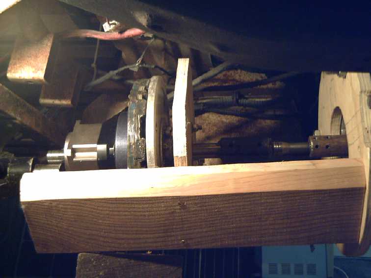 Test fitting the wooden housing
to the truck
motor. (Metal would interfere with the magnetism.)
Test fitting the wooden housing
to the truck
motor. (Metal would interfere with the magnetism.)
The top two 2 by 6es had to be unscrewed and trimmed to fit around
obstacles, leaving the center parts "sticking up".
The whole wooden assembly will be glued by epoxy and well epoxied, and
all gaps will be covered.
* *
* * *
Later in looking over some parts on the shelves for the
motor (below), I realized that having finally created a great magnetic
variable torque converter, I can scrap all kinds of parts of a lot of
the older experiments that I am definitely not ever going to use.
Since I started in 2008 I've mostly been accumulating things rather
than getting rid of them.
Everything that "just might be useful" until this
point was well kept, because when I went to make the converter that
proved successful I found all the parts I needed to put together the
prototype unit for the truck. It is marvelous now to disassemble all
these old things, return nuts and bolts to the drawers, UHMW plastic
parts into the bucket to melt down and reuse, metal pieces to bins or
the
garbage, and to clear off some shelf space!
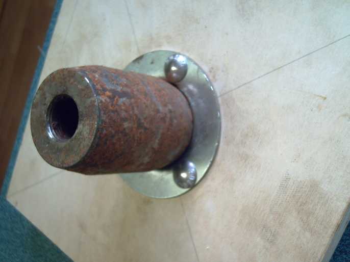
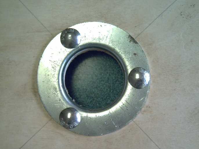
Unipolar BLDC "Electric Hubcap" Axial Flux Motor
 Someone had
told me that Sheldon had acquired a CNC plasma cutter. As I was going
to his town, Masset, on the 25th for the first time in months, I took a
piece of 1/8" steel with me and got his last name & phone# from
someone. I was directed to his impressive shop on Tow Hill Road. He had
just finished something else and to my delight immediately set about
cutting me a
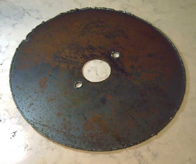
330mm diameter magnet rotor from my piece. The "kerf" was taken from
the inside
of the cut and it didn't go very smoothly. It ended up 326mm with a
small gouge. He said he would chalk it up to "a learning experience"
and didn't charge me. Unlike abrasive waterjet, there was lots of
knocking off "slag" and grinding to smooth off the edges.
Someone had
told me that Sheldon had acquired a CNC plasma cutter. As I was going
to his town, Masset, on the 25th for the first time in months, I took a
piece of 1/8" steel with me and got his last name & phone# from
someone. I was directed to his impressive shop on Tow Hill Road. He had
just finished something else and to my delight immediately set about
cutting me a
330mm diameter magnet rotor from my piece. The "kerf" was taken from
the inside
of the cut and it didn't go very smoothly. It ended up 326mm with a
small gouge. He said he would chalk it up to "a learning experience"
and didn't charge me. Unlike abrasive waterjet, there was lots of
knocking off "slag" and grinding to smooth off the edges.
I now have:
(1) A place on the island to go to get pieces of metal computer cut to
my specs (I'll bring G-Code or .DXF files), and
(2) a magnet rotor plate for the long-planned motor! (It's good enough.)
New rotor size for unipolar motor (24 magnets when done halbach) versus
old 10 inch (18 m-h.)
 [26th] I knocked off the "slag", ground and
filed the rim "smooth". It doesn't look as imposing as I feared - nor
at 326mm, as imposing as my original estimates of the diameter needed
to fit everything, of 400 or 370 mm diameter.
[26th] I knocked off the "slag", ground and
filed the rim "smooth". It doesn't look as imposing as I feared - nor
at 326mm, as imposing as my original estimates of the diameter needed
to fit everything, of 400 or 370 mm diameter.
Intending a Halbach magnet configuration I made this
rotor just 1/8" thick, and the new 326mm O.D. rotor weighed just 2135
grams, where an old 250mm, 5/16" thick one for an original Electric
Hubcap motor weighed 3031 grams (both without magnets). One sees that
the motor can thus be lighter for its size - another benefit of Halbach.
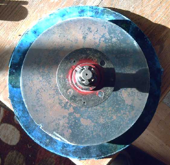
Checking the
326mm rotor to
make sure the planned 12 coil motor will work out well at that
diameter
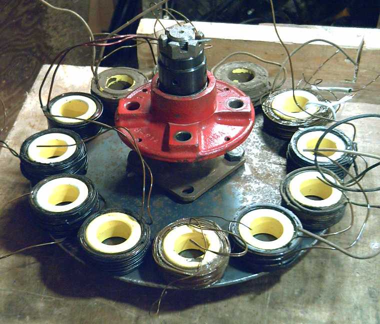 I grabbed some of the coils and
set them around the rotor to see if 12 coils would actually fit within
a 326mm framework without jamming them too close together. It looked
reasonable.
I grabbed some of the coils and
set them around the rotor to see if 12 coils would actually fit within
a 326mm framework without jamming them too close together. It looked
reasonable.
[27th] In OpenSCad I drew up a jig for putting magnets on the rotor,
with a little pocket to slide each magnet into in exactly the right
place. Now to use it I have to get some DXF to GCODE program working,
then actually get my CNC router to cut it out.
[28th] Owing to plasma cutter hiccups I drilled four mounting holes by
hand - same positions as 4 inch circle car tire studs since I''m using
a 1 inch trailer hub and stub axle with flange, with the flange and hub
both having the same bolt pattern. I got them pretty well centered and
aligned and it fit right on.
I couldn't get "DXF2GCode"
to work and I gave up. Instead I spent a day with a spreadsheet and
other software putting in numbers and formulas to manually create the
required GCode! I set the paths to run the router an extra 1/8" to get
the 1/4"
router bit right into the corners. Otherwise it would have been a lot
of filing plastic to square them, so it's better.
Next: trying to get the CNC router that I've never
actually used to actually cut the template.
 The next work
after that will be pieces for alume molds for the PP (non-magnetic)
stator components. (I still need to finish that plastic recycling
oven!) This flat circle PP piece for the windplant idea is just about
the
right diameter. The motor will want some more complex shapes, but
there's the idea.
The next work
after that will be pieces for alume molds for the PP (non-magnetic)
stator components. (I still need to finish that plastic recycling
oven!) This flat circle PP piece for the windplant idea is just about
the
right diameter. The motor will want some more complex shapes, but
there's the idea.
Obviously the motor won't be finished for quite some time,
and the microcontroller based 6-phase unipolar motor controller needed
to run it will stretch the project out still longer. But at last I've
started the 95% "ultra-efficient EV" motor!
In
Passing
(Miscellaneous topics, editorial comments & opinionated rants)
Amazon:
A Den of Thieves!
Fraud,
Espionage & Duplicity
Probably a year or so ago now I ordered a book from
Amazon.com . It was the only place I saw where I
could get that book. I noticed on a credit card statement last month
that there was
a bill from "Amazon Prime" for around 20$. It seemed like a long time
since I had made the purchase. Wasn't that already paid long since?
Hadn't I already seen the bill on a previous statement? But I ignored
it. This month there was another one for a similar but not identical
amount! I went back over my bills: ever since I ordered the book Amazon
has been billing me 14.99 $US each and every month! "Amazon Prime" it
says. I don't know why this wasn't raising red flags with me much
sooner. Once or twice it was the only charge on my card. I just wasn't
paying attention, and of course I'm annoyed with myself for being
asleep at the wheel for so long.
But I very deliberately had never, ever intentionally
opened an "Amazon Prime" account - I wanted nothing to do with it!
I don't even know what it's good for. Amazon has fraudulently been
billing me monthly ever since my order. I phoned
the credit card company and asked that the charges be reversed. This
request about Amazon Prime was by no means a new one to the lady I
talked to.
She said that somewhere in there I had accidently opened an "Amazon
Prime" account when I made the purchase, so it "wasn't fraud". She
couldn't reverse the charges. (Later someone else told me that had
happened to him too, and to someone else he knew, but that they had
caught it soon and had the charges reversed.) It was probably some
inconspicuous
checkmark in a box that I would have had to UN-check to NOT open this
so-called account when I made the purchase. Or something devious like
that.
I said maybe technicly it wasn't fraud [in some legalistic
sense] but really it was fraud, wasn't it? She agreed. It has cost me
way over 200$ for nothing - maybe more. That's probably the value of
any
and all of the two or three orders I've ever placed with Amazon - and
all at 100% pure profit for them for doing nothing. It is sad that
one of the biggest companies in the world can get away with
illegitimately, deceptively bilking unsuspecting customers month after
month. Big corporations - especially American & Western ones - have
no shame!
I went to the amazon.com web site to close the account -
sure enough the account existed, at my old email address! But searching
page
after page, if there was any option anywhere to close your account, it
was really well hidden. Finally I went to the "payments methods" page
(where three of my credit cards popped up, however many years ago I had
used them)
and found a way to cancel the one not out-of-date credit card they were
charging to as
being a valid payment method, leaving (I hope) no valid payment methods
for further charges to "my" so-called "account". (And even then, the
box to cancel it without putting in a new payment method first was
"lighted out" type and border - made
as
inconspicuous as possible as if it wasn't an available option.)
I thought that was it but soon Amazon was leaving messages
on my cell phone complaining that my account was in danger. I've never
given that cell phone number out to anyone except a very few friends. I
suppose that as soon as a friend entered my name and number on their
phone the whole world knows it. Or they just saw a phone sitting at the
location of my old phone and messaged to it. Either way they're
obviously spying with very sophisticated spyware on everyone across the
whole cell phone network. By phoning a number they should never have
had, they've admitted it!
I sent "report spam" and blocked their number.
I will never deal with Amazon again, even if I have to
forgo getting something I want. But they've already made more free
money off
me than if I had ordered 1000$ worth of actual merchandise. Someone
suggested I call them and try to have all those charges reversed, but I
doubt if they will (maybe the last one or two - I can hear it now:
"It's been too long") and I don't have the stomach for it.
(AliExpress.com has no monthly fees. You pay only when you
buy
something and it's usually cheaper. I've never had an unexpected or
fraudulent charge to a credit card there. And there's e-bay.)
Apparently I still hadn't or haven't heard the
last of them. On the 28th there was a computer call to my home phone -
the number I actually gave them. The call display said it was from a
local number, one digit different than a friend's (which on calling it
said the number wasn't in service) and started out something like "This
is Amazon... unfortunately your recent purchase was billed to your
credit card that..." At this point I assumed it was some scam to get a
credit card number from me and I hung up. Obviously Amazon doesn't have
a local Haida Gwaii office nor had I purchased anything in (?)a year.
Now I think I probably was Amazon and they were calling because
they couldn't keep billing me monthly for nothing. Calling from a
"local phone number"??? About a "recent purchase"??? (If they have
charged my card again, this time it's clearly illegal.)
Car
Key
FOB
Hidden
Health
Hazard
I noticed several times that I was feeling a small but sharp pain in my
right leg, which had no apparent explanation. It felt like it was a
little deeper in than right at the skin and there were no marks. I had
already noticed that I seemed to have lost the feeling in the skin in
the same area some time ago. Deeper down had feeling and I could feel
pressure, but if a spider was crawling across my leg hairs there, I
wouldn't have felt it.
One day it dawned on me: that was right under where the
"key fob" for the Nissan Leaf car sat in my pocket! Previously, the
cell phone had done funny things to my other leg, making it twitch and
vibrate, and I had also lost skin feeling there (which I hadn't until
now attributed to the phone - after all, it had started on the other
leg too). I had stopped carrying it.
Now here it was, another source of microwave(?) radiation
right against my skin, evidently causing trouble! I took the "fob" out
of
my pocket. I hope neither the phone nor the "fob" has started a cancer!
(Yes, people do die of cancer from cell phones.) I'll have to have it
in my pocket when I drive anywhere, but I'll keep it away from me
otherwise. Leaving it in the car would invite theft - and what if the
key is inside and the doors lock themselves, as they do if I press the
wrong button? I can see there'll be many episodes of having to go back
into the house for the FOB just after I've got into the car to drive
off. And many of forgetting to take it out of my pocket at home.
I knew I never liked the idea of "key fobs"! I just didn't
know why, other than that they need batteries, might die if they get
wet, and are costly to replace. Here is a much bigger reason. One more
thing to worry about.
Smol
Thots
* Many still rail against electric cars, saying that "they aren't the
future" and make arguments against them that don't hold water when
examined. They will say making the car itself uses "X" energy resources
and so the vehicle doesn't become "energy neutral" for many tens of
thousands of miles, and never if it's used in an area where electric
plants run off coal. But they offer no alternatives except to finish
using up the world's fast depleting petroleum deposits. And then?
Furthermore, they don't say how much energy it takes to
produce a gasoline powered vehicle to compare figures with, or how long
it
takes that to pay off the energy used in making that - which of course
it never does. And they don't consider that many homeowners with
electric cars also have rooftop solar power and produce more
electricity than their car uses, or that an electric car simply uses
less energy than a gasoline vehicle owing to its higher efficiency and
that anyway any power station burns its fuel more efficiently than a
car does.
And they complain that "there isn't enough lithium for the
batteries" and that "it's mined in third world countries where there
are no environmental regulations and slave wages." First of all, they
have no such scruples about any other metal or where it's mined or how
it's processed - only
lithium. And Australia - reputedly not a "third world country" last I
heard - is the world's leading supplier of lithium. Australia has also
just created a process that extracts twice as much of the lithium from
the ore as presently. Also the naysayers discount that there may ever
be any other
type of EV battery besides lithium. Nickel-metal hydride flooded EV
cells (that never explode) were just as good before the oil company
that ended up owning the factory shut it down, and I now (after many
experiments
this month and some conclusions that remain to be proven) fully expect
success in my attempts to create 'everlasting' gelled nickel
manganates-zinc cells that should be the safest batteries, cheap and
with a high energy density.
* How many of the people complaining about electric cars are the same
ones saying we can go on increasing the global population ad infinitum
because "new technology will always solve our problems"?
* Jesus once said "The truth never suffers from honest examination."
[Urantia Book 153:2.11]
All those who rail against freedom of speech today, is it because they
are afraid of truth or don't want it spread for one reason or another?
Do they not want to face truth themselves and want others who might, to
not be exposed to it? Some are afraid of others knowing truth because
of things they themselves have done that might become known. But many
simply hate to face change (even tho they would never want to live in
the
"unchanged" world as it was 100 or 1000 years ago) to the point that
they would try to ban new knowledge. "Know the truth, and the truth
shall set you
free." - Jesus again. [Bible, John 8:32] We should seek various
different views from diverse sources in attempting to discern the most
accurate picture of major events around us. The mass media all have
just one and the same view.
* The economists at the world economic forum in Davos have indicated
that
they've prepared for the next pandemic -- whatever it is. (As long as
it kills less than one person in a thousand who contracts it, like
statistics seem to now show covid did?) Vaccine passports mean people
won't
be locked down and unable to travel, and all is agreed on. A minor fly
in the ointment might be that we can't possibly have any clear idea
what sort of disease the next pandemic might be, or how deadly or
how contagious it will be. (Unless it's already been created in a lab
somewhere.) But from the sounds of the economists making
regulations for it, it seems there must already be an experimental mRNA
vaccine mandated for it, since they're putting the vaccine passports
into place
already. Just in case it's a virus and not something else that can't be
vaccinated against.
Next they should get some doctors and health professionals
in to mandate the economic and industrial measures for
improving our economies.
* Authoritarians are those who think they can run your society, your
economy and your own life better than anyone else including yourself.
They
don't need input from others or to gain better understandings
themselves, just to give orders and make everything fit their vision.
Peasant farmers are so ignorant... great leader Mao had
all the little birds they had been putting up with, ignoring or maybe
even liking and feeding, killed so they wouldn't eat any of the seeds
or crops. One problem solved! Instead swarms of bugs ate the crops
because there were no birds to keep their numbers in check, and China
had famine. In more recent decades people were given freedom in China
and China rose up from poverty and prospered. Now an authoritarian
leader has
come in who is jealous of prosperity and who wishes to "nationalize"
all the prosperous private businesses. And who in some strange paranoia
also has no hesitation locking down a city of 20 million people for
months
because of one case of Covid. A crash in living standards,
economy and creative progress - or a great and doubtless violent
political clash - seems inevitable. (In fact, living standards are
crashing, and after I wrote this and before the end of the month,
political confrontations have already arisen across the whole country -
masses
of people clamoring to "End the CCP!" and for Chi Jinping to "Step
Down!")
Today there seem to be far too many of these authoritarian
types of
people around and often running the show, to the detriment of society
as a whole. They make law after law, each to myopicly solve one seeming
problem but always applied zealously in unintended situations with
wider repercussions that all put together leave everyone unable to to
what is desirable or needed without contravening one ordinance or
another. Life becomes more and more complicated.
Freedom is better. Somewhere, bit by bit over the decades
and a couple of centuries after having gained it, most of the world
seems to have lost it again.
* Freedom and Responsibility go hand in hand. Freedom is dangerous and
sooner or later lost in the hands of people who abuse it - or who
don't understand what their responsibilities are. In today's case, we
are losing our freedoms not only because of people who have been
permitted to abuse the freedom given them, but because with all the
freedom-granting progress in governance, medicine, food production and
so on, we have missed the most essential thing: as more and more people
survive into adulthood and live longer and longer lives, the population
can't be
allowed to grow unchecked.
We are long past the time when calamity and a catastrophic
die-off of people could have been avoided. Probably the last and maybe
the only time that could have worked was in the early to mid 1960s
immediately following the invention and availability of the birth
control pill. At that date we were already over the 3 billion mark that
is probably about the maximum sustainable population for this
planet,
and beyond which life has become increasingly "cheap". Since then we
have been drawing down future resources (and non-renewable resources)
to feed and power the present
at an ever increasing scale as the population grows, and just now are
suddenly running out of many needful things.
EIGHT BILLION PEOPLE! Who would ever
have thought it could get so out of hand? But the measures would
have had to have been applied worldwide, not just in the developed
world, and I'm not sure the prolific peoples of the fastest growing
countries could have been convinced of the need at that time. Today
probably yes. Then... probably not. OTOH there are still plenty
of people everywhere who don't think the present population is a
problem even as the environment and ecology that sustain us are
crashing
down, one more adverse event, one more species extinction, at a time
all around us.
ESD
(Eccentric Silliness Department)
* English spellings are weird. They are created ad lib by weird and
conflicting spelling conventions. We've all eaten "ghoti" (gh as in
"enough", o as in "women", ti as in" fraction": ghoti = fish). And then
there's two completely different sounds for "c"....
How about a ckhourin pad? (scouring pad - "in" as in "sink"; "hour" as
in "hour") or a
lighn? (line) or or
or... btongcre (tinker - bt as in "debt") or or or...
* Here's the title for a new book I have no intention of writing:
"Ukraine: From Breadbasket to Basketcase". (No doubt the territory will
eventually recover and reassemble in new form(s) agreeable to the
peoples who live
there when all the authoritarians are through meddling with it!)
* And of course some have proposed to replace the US dollar in
international trade with "a basket of national currencies". But since
none of them are tied to anything physical and can be printed ad
infinitum, I would rather call it "a basketcase of national
currencies." (In 1950 10$ would buy a week's worth of groceries for a
family. Today 10$ will buy one or two small grocery items. But it's
similar everywhere.)
* Someone wrote in a comment under a video: "Only trust half of what
you see on the
internet" - Abraham Lincoln
* How does a jugglernaut keep on going and going in space, when the
jugs he's juggling just don't come back down?
* Word Jumbles, anyone?: aaabcehillpt deorr -- (If you get the
second word, the first one is intuitive.)
* If someone has "doctor" in their name, does it mean they've been
indoctorinated?
* Riddle: Where are "Satis"
made?
A:
In
a
satisfactory. (groan!)
"in depth reports" for
each project are below. I hope they may be useful to anyone who wants
to get into a similar project, to glean ideas for how something
might be done, as well as things that might have been tried, or just
thought
of and not tried... and even of how not to do something - why
it didn't
work or proved impractical. Sometimes they set out inventive thoughts
almost as they occur - and are the actual organization and elaboration
in writing of those thoughts. They are thus partly a diary and are not
extensively proof-read for literary perfection, consistency,
completeness and elimination of duplications before
publication. I hope they may add to the body of wisdom for other
researchers and developers to help them find more productive paths and
avoid potential pitfalls and dead ends.
Electric
Transport
Magnetic Variable Torque Converter with Planetary Gear
I spent much of the month
on new chemistry battery experiments and the torque converter project
went into "low gear". But I did get a few things done on the "proper"
housing to try and get the truck on the road.
 [?] At some time early in
the month cut a square of plywood for the
motor shaft bearing, and punched an "almost perfect" metal flange out
just slightly to fit that bearing, with a slightly cone shaped thing I
found and the hydraulic press.
[?] At some time early in
the month cut a square of plywood for the
motor shaft bearing, and punched an "almost perfect" metal flange out
just slightly to fit that bearing, with a slightly cone shaped thing I
found and the hydraulic press.
 Just the right size to slip the
bearing into!
Just the right size to slip the
bearing into!
I put together
the transmission housing with deck
screws and tried to mount it to the motor under the truck. It didn't
quite go in, and I made some marks on the two
upper 2 by 6's to cut them to clear obstacles. It was awkward because I
couldn't get it attached to the motor. I cut the angles wrong and they
still didn't fit, so I did it again. They were closer.
[16th] It finally occurred to me that
the second plywood bearing holder
would be identical to the first. I cut the second square of plywood.
The hole saw wandered way off my 1/8 inch pilot hole and I had to do it
all over, with a larger pilot hole. I filed it down a bit and mounted
the pressed bearing holder. I got the housing bolted to the motor with
the upper 2 by 6's removed and marked them for a bit more trimming.
Then I decided to order a 10 to 1 planetary gear instead
of the 5 to 1 as the variable ratios looked better. It has a slightly
different size so I had to stop and wait for it to arrive. (Dec. 3:
Tracking says it hasn't left China yet! ...by Christmas?)
Axial
Flux
Unipolar
BLDC
Motor - 5KW?
[25th] Someone had told me that Sheldon
(from whom I got the 36V, 3.5KW forklift motor for the Chevy Sprint in
2019) had acquired a CNC plasma cutter. As I was going to Masset for
the first time in months to look in the hardware store for something
not available in QC, I took a piece of 1/8" steel with me and got
his phone# from someone. I was directed to his impressive shop on Tow
Hill Road where there were a few other people, dead cars and much
equipment. (I'm not sure if they were employees or what.) He had just
finished something and immediately set about cutting me a 330mm
diameter magnet rotor from my piece. He cut it without making a drawing
file, just typing in some numbers and moving the arm to the starting
position. It didn't go especially well and the "kerf" was on the inside
of the cut, so it ended up 326mm with a small gouge. Then the four "lug
nut" bolt holes didn't go well either. It made two then didn't arc, and
I was left to drill the other two. He said he would chalk it up to "a
learning experience" and didn't charge me. In addition, the cuts were
nothing like as clean as those made by abrasive waterjet cutters. There
would be lots of grinding to smooth off the edges. (Hammering a
screwdriver at them broke off most of the "slag" seen in the image.)
I mounted it on the axle ("trailer 1 inch stub axle with
flange") and found that even the two bolt holes that were cut were
about 2mm off center, so it wobbled. I abandoned them and
drilled four new holes at 45° to them.
But I now have two things: (1) A place on the island to go
to get pieces of metal computer cut to my specs, and (2) a rotor plate
(good enough...). Next time I'll bring a .DXF CAD file of the part(s)
to give me exactly what I want.
The next parts will be pieces
for alume molds for the PP
stator components. (Metal parts would interfere with the motor's axial
flux magnetic operation.) Finally it looks like I can start to move
forward with this long-planned motor project - and without having to
make a CNC plasma cutter (or HHO torch cutter) myself. Something I do
still need, IF I'm going to cast pure PP parts, is to finish the
plastic recycling oven. (Although, an regular kitchen oven should be
big enough for the motor mold parts!) (Shown with molded PP circle
under it. I have plans for more complex shapes for the motor housings.)
The other way is to make UHMW plastic molds and go back to
PP-Epoxy composite parts. (I could, I presume, make UHMW molds on my
own CNC router table... Which has never yet had a real test and which I
am rather apprehensive about using. Then again, I can get some bigger
UHMW pieces for molds by melting down some of the smaller pieces I
already have... again in the plastic recycling oven. Experience on the
phone so far suggests that might actually be more practical than trying
to buy larger pieces and have them shipped here.) But direct molding of
PP-only components would be much less labor intensive for production,
and PP is good, tough plastic.
[26th] I knocked off the "slag", ground
and filed the rim "smooth". It
doesn't look as imposing as I feared - nor at 326mm, as imposing as my
original estimates to fit everything, of 400 or 370 mm diameter.
Intending a Halbach magnet configuration I made this
rotor just 1/8" thick, and the new 326mm O.D. rotor weighed just 2135
grams, where an old 250mm, 5/16" thick one for an original Electric
Hubcap motor weighed 3031 grams (both without magnets). One sees that
the motor will be lighter - one benefit of Halbach.
[27th] In OpenSCad I drew up a jig for putting magnets on the rotor; a
little slot to put each magnet into in exactly the right place. Now to
use it I have to get some DXF to GCODE program working, then actually
get my CNC router to cut it out. In spite of testing the stepper motors
and getting them to move the carriage across the CNC table and move the
router up and down, I haven't actually tried the router out yet. I have
little confidence that it will be made to work flawlessly without much
work.
[28th] I drilled the four mounting holes (12mm) - same positions as 4
inch circle car tire studs since I''m using a 1 inch trailer hub and
stub axle with flange, with the flange also having the same bolt
pattern.
A new idea occurred to me: to integrate the motor and the
magnetic torque converter. The rotor would have the motor magnets on
one side and the converter magnets on the other. The alume disk would
be on the adjacent planetary gearset body. A PP housing could
accommodate both with a bearing at the end on the output shaft of the
converter, to go straight to a drive shaft or CV shaft as desired. This
would make the most compact unit.
This would be for a production unit. It would be pretty
hard to use that end of the "trailer axle with flange" as the motor
output shaft - almost no shaft sticks out past the flange to attach to
the planetary input. If it were to be produced, there
would be a need for at least 2 or 3 different models. One would be for
"straight to CV shaft" which would need a large planetary to handle the
full torque of the wheel. A smaller planetary is needed if there is a
subsequent gear reduction, as in the 2.2 to 1 differential in the
truck, or some other gear to add further reduction to increase the
motor speed. This is desirable because even at 150 KmPH the motor speed
would be only around 1500 RPM, whereas it should be capable of over
double that and would deliver more power at higher speed.
A variant of the "straight to CV shaft" one would also
incorporate my recent idea of having a mechanical brake away from the
wheel. Instead it could be on the output of the planetary, ie, at the
CV shaft. This would remove the brake mechanism from inside the wheel
where it is unsprung weight and subject to moisture, dirt and grit from
the road. The wheel would be lighter and so the vehicle would have the
best possible handling. The brakes would last far longer. (This would
assume there was one unit driving each front (or rear) wheel (if not
all four wheels) to make braking symmetrical side to side.)
[30th] I downloaded the latest version of .DXF to .GCode ("DXF2GCODE").
Whenever I tried to open a .DXF file, it hung with a little spinning
wheel. Same as before, IIRC. I'm not paying a hefty annual license fee
for another product to use it once every 2 years. I give up! I'll have
to generate the g-code manually, using a spreadsheet to do the angles,
as I did before for previous motors et al. Yetch, manual labor!
[Dec. 1st] I spent the day with spreadsheets [instead of editing this
report], putting in numbers and formulas, and repeating everything ad
infinitum (for 24 magnets!) for each mistake or change. Even with "fill
down" in the spreadsheet things were less than automatic when every
third magnet is different from the other two. Then I had to pass the
numbers through Libre Office Writer to delete all the tabs the
spreadsheet inserted, then used a simple text editor, and a program
called "CAMotics" that would nicely display what the router would cut
on the CNC machine (but could not edit the GCode). CAMotics wouldn't
take multiple commands on a line, so I had to insert 144 "RETURN"s each
time I changed something to separate the figures, into one X,Y point
per line. It could have been so simple with something to convert a .DXF
file to GCode. Well, it's done now.
Next: trying to get the router that I've never used to
actually cut the template.
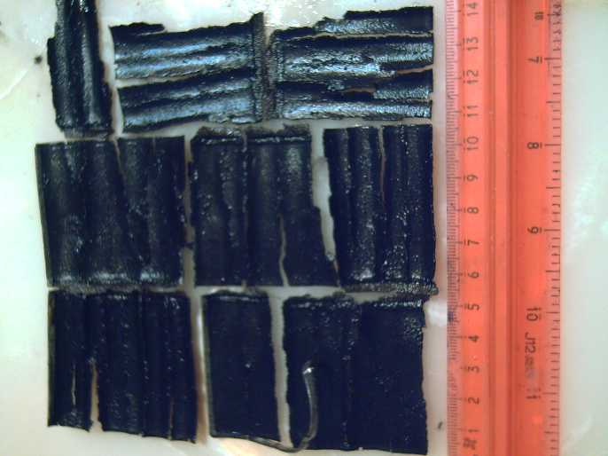
Other "Green" & Electric Equipment Projects
Peltier Cooler Performance: Greatest Cooling & Lower Power
is attained by running them at 9-10 volts
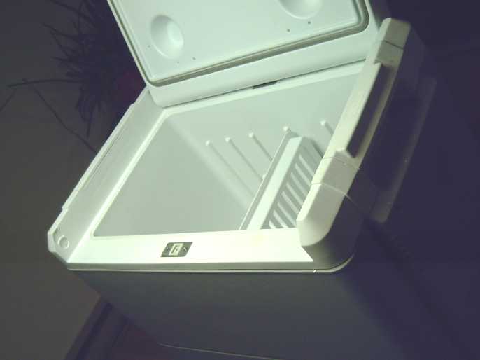
[6th] Someone brought me a
Coleman
peltier camping cooler from the thrift shop. It didn't seem to work. I
spent a couple of frustrating sessions fiddling with it and wondering
why I was wasting my time on it. It was a mystery: the peltier module
was working and drawing tens of watts, and everything seemed in order,
but it didn't cool. I rearranged the heatsinks and module more than
once, thinking it somehow wasn't making good thermal connection.
Finally I disconnected the fan motor and reversed the
wires. It worked! The motor runs both the inside and the outside fan
with one on each end of the axle, which sticks through the cooler's
wall. Someone had apparently switched the fan motor polarity WRT the
peltier polarity, and it just didn't cool the outer heatsink well
enough to let the inner one get cool.
Now that it was working... going back a way I had noticed
from Peltier module performance charts that the higher the voltage the
more heat the hot side made, and even with excellent heatsinks the heat
transferring across the unit made it harder for the cold side to cool.
The coefficient of performance (COP) went up as the voltage and power
went down. So I had surmised that they might work just as well at lower
voltages and powers. I even thought 6 volts instead of 12. I'm not sure
why I didn't try different voltages
with a lab power supply back in 2012 to check this out, but I only used
the 12V solar power. And I rather hacked up my old Mobicool peltier
cooler from Canadian Tire.
So now I had a properly working peltier cooler, and a DC
to
DC converter plugged into my 36V DC solar power system. I had a patch
cord from the 12V "Mini T-Plug" to alligator clips, which I clipped
easily to the cooler plug's flat pins.
Tests & Measurements
I hooked it up and tried running it at 12, 11, 10, 9, 8,
7, 6.5 and 13 volts. This applied to whole unit including the fans as
well,
which were rather noisy but not as bad at lower voltages. The tests
occupied much of the day and evening. Vexingly I
only found two of my digital thermometers and in one the batteries were
dead, so tabulating inside versus outside temperatures with the room
temperature fluctuating with woodstove heat was a bit tricky. The
cooler
takes a long time for the temperature to 'stabilize' and the
thermometer reading takes a long time to stabilize at a new temperature
each time it's moved between inside and out. But I can say the
following:
* 12 volts (45 watts) or even 11 volts (39 watts) didn't seem to work
as well as slightly lower voltages. I was finding temperature drops of
around
11°C. (eg, 18 in the room / 7 in the cooler.)
* A couple of hours later at 10 volts (30 watts) I read 20° /
7.5°, which is a 12.5° spread - seemingly about as good as
Peltier coolers get.
* At 9 volts (just 25 watts) it stayed at about 7.6° but I didn't
measure the room again. (Finally I remembered I had another digital
thermometer hanging outside the front door and brought it in.) Best
estimate drop was just under 12.5°.
* At 8 volts and 20 watts the cooler temperature crept up to 8.1°.
The room may have cooled slightly (by ~.3°?) Difference: 11.7°.
* At 7 volts and 15 watts it gradually rose to 8.4°. The room had
cooled a bit (to 19.5°?) so the spread was down to 11° or so.
(That's 1/3 the power of 12V to get the same temperature drop!)
* At 6.5 volts, 13 watts, after a while it had risen to 8.9°, while
the room had cooled to just over 19° - spread about 10°.
* I raised it to 13 volts, 53 watts, last. The temperature quickly rose
to 9.1°, probably related to the fans speeding up. Over the course
of an hour it was down to 8.3°. That small, gradual drop from what
6.5 volts had kept it at didn't say much for running it at higher
voltages.
Cooler
Supply
(Volts)
|
Cooler
Power
(Watts)
|
Cooler
Temperature
Drop (~°C
below room)
|
13
|
53
|
11.7
|
12
|
45
|
11
|
11
|
39
|
11
|
10
|
30
|
12.5
|
9
|
25
|
12.4
|
8
|
20
|
11.7
|
7
|
15
|
11
|
6.5
|
13
|
10
|
(Watt figures are rounded to the nearest watt. Believe it or not.)
Conclusions
 Expanding
slightly on prior theoretical expectations, I
conclude (similar to my previous cooler tests), that a "12 volt"
Peltier element and cooler cools best at 9 to 10 volts. Certainly if
one has limited energy available (eg, solar in winter, car battery) 8
or 9 volts is
a good choice. To ultimately minimize power consumption while still
having it cooling, it can go down to 7 or 8 volts - maybe even 6 (and
probably just over 10 watts) if the fan(s) keep running. (My "8.5 to
100 VDC" power meter craps out below 7V. At 6.5 I could barely read the
display even with the backlight turned off.) Running it at 12 volts -
or 13 to
14 as in a running car - seems to be nothing but a waste of energy
unless you're trying to make heat in the room or vehicle.
Expanding
slightly on prior theoretical expectations, I
conclude (similar to my previous cooler tests), that a "12 volt"
Peltier element and cooler cools best at 9 to 10 volts. Certainly if
one has limited energy available (eg, solar in winter, car battery) 8
or 9 volts is
a good choice. To ultimately minimize power consumption while still
having it cooling, it can go down to 7 or 8 volts - maybe even 6 (and
probably just over 10 watts) if the fan(s) keep running. (My "8.5 to
100 VDC" power meter craps out below 7V. At 6.5 I could barely read the
display even with the backlight turned off.) Running it at 12 volts -
or 13 to
14 as in a running car - seems to be nothing but a waste of energy
unless you're trying to make heat in the room or vehicle.
Peltier coolers always suffer from comparisons to
compressor refrigeration. At 9 volts and 25 watts this one cubic foot
cooler maintains about a 12.5° temperature reduction from ambient.
At 60 watts my (pretty new) 5 cubic foot freezer maintains somewhere
around 30-40°. And it only runs half the time to do it, making it
around 30 watts. And with this particular peltier unit, the buzzy fan
is more
annoying than freezer's compressor.
I still await some superior Peltier modules with higher
COPs made by some novel new technique or materials. (10 years so far...
Is there anything that transmits electricity but insulates heat?
Electromagneticly induced current across a thermal barrier? How might
that be employed inside a Peltier module? Probably not.)
Repeat Remarks: Heat Sinking Peltier
Modules
I will again say that to my mind pure alume or
copper (or even silver) are heatsinks of choice for peltier modules
rather than the common alume alloy heatsinks. Pure alume
conducts heat much better than any alloy and pure copper is still
better. If you are trying to keep a
transistor below 100°C, alloy is fine. But in a peltier module
every degree is critical and any difference in the junction
temperatures between the ceramic surface of the module and the
contacting surface of the heatsink are dead loss. Think that if a
better heasink can keep the hot side one degree cooler, and the cold
side one degree warmer, the Coleman cooler would go from cooling by the
maximum temperture drop I found of 12.5°, to 14.5°. If the
outdoor temperature was 21°, the food inside would stay at 6.5°
instead of 8.5°. Furthermore, the heat transfer across the module
would be reduced, perhaps making a higher voltage work better, which
just might (and I haven't worked this out or tried it) further increase
the potential cold side drop.
If I didn't have other projects I'd still be tempted to
make copper block contacts to the module, expanding to a larger contact
area attached to pure alume heatsinks. (The copper bar that connected
the module cold sides to the ice tray in my "super insulated" peltier
shallow chest
fridge [10 years ago TENews #??] certainly seemed to work well. Now
that I think about it, I should have had another big, fat copper bar
connecting the hot sides to the outer heatsink, too!)
Winter
Gardening
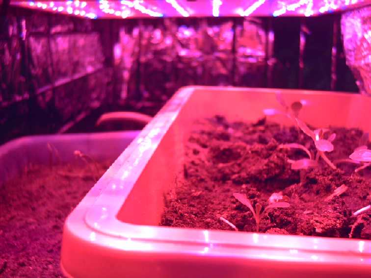
Window & LED Gardening
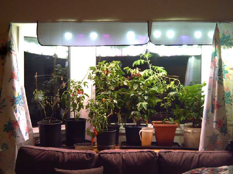 It seems a shame to give up pepper and tomato plants after spending all
summer growing them, so this year I put some cherry tomatos and "orange
mini bell" and "banana" peppers in pots instead of in the ground. And I
still have the coffee plants. (I wish I had put a large tomato plant in
a pot to bring in - I got great tomatos into October when it got too
cold. Well, next year!)
It seems a shame to give up pepper and tomato plants after spending all
summer growing them, so this year I put some cherry tomatos and "orange
mini bell" and "banana" peppers in pots instead of in the ground. And I
still have the coffee plants. (I wish I had put a large tomato plant in
a pot to bring in - I got great tomatos into October when it got too
cold. Well, next year!)
As the weather got cool I brought them in
and made a shelf under the bay window. Now as the days got short and
dull I took some of my "indoor LED garden lights and mounted them at
the top of the window. I put up some reflectors and some white
tablecloth "curtains" to make it brighter. It seems very satisfactory,
making use of what little daylight does shine in as well as 8 hours of
bulbs.
But I was trying to water every second day, and I must
have missed a day. Possibly two. My biggest cherry tomato withered and
didn't come back; another (far left) had a single small live branch
left. I
brought in the third one, that had been in the kitchen. It had a single
flower now starting to turn into a fruit, and now a couple more. But it
drooped and almost died too. All the peppers looked like they had been
through some drought too. Now I don't dare miss a single day watering.
The banana peppers turn yellow first, then red. They're sweeter than
the orange ones.
 And I planted
a rectangular pot of romaine lettuce and one of spinach about 6 inches
under two 40 watt red and blue LED "grow light" panels. The lettuce was
soon getting tall and spindly, and on December 3rd all of them fell
over. There just wasn't enough light. I piled some dirt around them
them to prop them up and then raised the pot so they were within 3
inches of the lights, which I then left on all day and night. and I put
up some alume foil at the front to reflect the light back in. (The back
was already reflective. The next day they survived and all started
their first leaf. I'd say they're just barely getting enough light now.
I'm certainly not impressed by these "grow lights"! But they are old
ones.
And I planted
a rectangular pot of romaine lettuce and one of spinach about 6 inches
under two 40 watt red and blue LED "grow light" panels. The lettuce was
soon getting tall and spindly, and on December 3rd all of them fell
over. There just wasn't enough light. I piled some dirt around them
them to prop them up and then raised the pot so they were within 3
inches of the lights, which I then left on all day and night. and I put
up some alume foil at the front to reflect the light back in. (The back
was already reflective. The next day they survived and all started
their first leaf. I'd say they're just barely getting enough light now.
I'm certainly not impressed by these "grow lights"! But they are old
ones.
Now a couple of spinach have come up and and are also
getting tall and spindly. I'd better find some more props and also get
that pot up to the lights before they keel over too!
(Now there isn't room to water them in place, and they're
quite heavy to move - ug!)
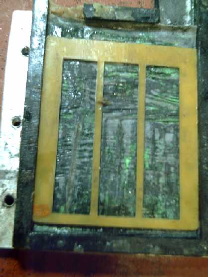
Electricity
Storage
Gelled Nickel-Zinc Batteries
[7th] I figured that for testing as I
was doing, the cell didn't need to be perfectly sealed. That could come
when things were basicly behaving as expected. And I figured that with
the external clamp plates, the beeswax on the joins should make a fair
seal when firmly pressed together, too. That meant I could now screw
the cell open and closed and try a lot more things faster. This is what
I should have done long ago.
 Previously I
had broken open another NiMH "D" cell and
taken out the NiOOH electrode (broken pieces). I put it in bleach to
charge it up.
Later I saw some tiny oxygen bubbles. Now I made it into a new
electrode which I painted with a mix of KCl solution, Sunlight soap and
a bit of SmO3. I used parchment paper as a separator paper and put in a
plastic spacer as well.
Previously I
had broken open another NiMH "D" cell and
taken out the NiOOH electrode (broken pieces). I put it in bleach to
charge it up.
Later I saw some tiny oxygen bubbles. Now I made it into a new
electrode which I painted with a mix of KCl solution, Sunlight soap and
a bit of SmO3. I used parchment paper as a separator paper and put in a
plastic spacer as well.
When I put it on it read under a volt again. It
charged up at 30mA to about 1.485 volts and didn't seem inclined to go
any higher. Could it be that at neutral pH the NiOHOH didn't stay
charged to NiOOH? That was what I was doing differently: I had
previously been using 20%:20% KOH:KCl to raise the pH. I'm trying to
avoid corrosive KOH. But I needed to do something to raise the pH. How
about some Ca(OH)2 to raise it to 12-13 but not to the "dangerous to
handle" pH 14?
I opened the top of the cell, wetted the electrode with
salt water and dabbed some calcium oxide onto it. It didn't seem to
have much if any effect, even over a few hours to let some dissolve.
Hmm... When I was doing the manganese negative electrodes
long ago
I had used a mix of NiOOH and MnO2 in the plus. I supposed it was
forming
nickel manganates, but I found found it didn't seem to recharge
properly, which is (I later found out) a characteristic of manganese -
Mn2O3 or Mn(OH)3 [valence 3] are insulators and so don't
recharge electricly to MnO2 [valence 4]. The cells that "should have
been" great got weaker and weaker with each cycle - and not from the
metallic Mn negatives. (Also the negative voltage was so high my
negative current collectors were bubbling hydrogen wherever they were
exposed to the electrolyte, a source of continual overnight
self-discharge, which I also didn't realize/understand until much
later.)
On a whim I opened the cell again, pulled off the top
current collector and dropped 3% hydrogen peroxide onto the NiOOH
pieces. IIRC this should DIScharge them. A fine froth bubbled up with
each drop until I had covered pretty much all of it. Then I put it back
together and onto charge again - 50mA instead of 30, and the voltage
came up to 1.9 volts. It still dropped rapidly when the charge was
removed. I worried that the zinc must be getting overcharged and making
hydrogen/zinc hydride. It still didn't stay up to voltage.
Back to basic basics!
[9th] Once upon a time, 11 to 10 years ago, I was getting better
results than I have been recently. Let's see... with no protection, the
zinc forms dendrites rapidly and the cell dies. The osmium doped acetal
ester layer helps. Agar... PVA... did I ever try using just the
dishsoap as the gel for the negative side? Or was that back when I was
making metallic manganese negative electrodes, before I started using
zinc? Far too much time between battery experiments: I lose my
continuity and forget just what I've done, time after time.
- I heated up the zinc electrode to 90° to dissolve off the PVA (in
preference to making a new one and coating it again). Lots of bubbles
came off the piece as it got hot.
- I cleaned out the cell case to "empty". Then I daubed a graphite
current collector on both sides with Ca(OH)2 and set it in.
- I put the new Ni(OH)2 electrode back in on top of that, as it was, no
changes, same separator paper.
(It has the salt solution with Sm(OH)3 and some dishsoap)
- I could see lots of green nickel hydroxide (powder) through the
separator paper. I didn't trust that it wasn't coming through, and
added another plain piece of parchment paper above it.
- I made a new larger separator paper and impregnated it with salt
solution including zircon and dishsoap, and wrapped it around the zinc
'trode.
- I left it with no top electrode and put in plastic spacers to fill
the cell, then closed the cell and clamped it together. (Hmm... not
much beeswax left around the edges. I'm not bothering to try to seal
it.)
Tests
This time the cell, even if it didn't take or deliver current very
well, charged and didn't rapidly discharge to some half-way voltage.
(16:30 PM) After a little while it was charging at 1.911V and 20mA, and
it took over a minute to drop to 1.7. It would deliver about .3 amps
into a short circuit momentarily. (16:45) Now .5 amps at .5 volts into
a 1 ohm load. (Drops off rapidly.) 1/4 watt, but at least it's real!
Now holding over 1.8 volts for one minute plus.
(17:30) Seems to have been a spurious reading... 0.3 amps
is the most I've read since, and it's been consistent. 1/9 watt. For 58
sq.cm that's a mere 5mA/sq.cm. Five times that would be encouraging and
20 times would be fabulous. But the dry cell NiOOH electrodes use
nickel foil (& powder?) for higher conductivity, and nickel
corrodes to just more NiOOH at any pH below 14. That's where the
graphite powder or carbon black, and or the monel or cupro-nickel
should come in.
Given my troubles with nickel manganate 'trodes, I think I
may just try making NiOOH ones with these different conductivity
enhancements. (Then I'll probably try nickel manganates again.)
In fact, I could open the present arrangement and
(hopefully) set the NiOOH electrode (made of all the little bits) out
on its separator paper again. Paint that with conductive carbon black
(let's call it "CCB") and a bit more Ca(OH)2. If it works, that should
at least somewhat increase the conductivity and hence the current
drive. OTOH, if it won't hold a charge after doing that, I'll know that
graphite/CCB has too low an oxygen overvoltage (at mild alkaline pH)
and is preventing the NiOOH from hold its charge.
The CCB didn't want to mix with the water. It mostly sat
floating on top by surface tension. I tried again with a little soap
mixed in, this time just to try to get the CCB to wet. The mix at least
looked black when painted onto the pieces of NiOOH from the dry cell
and onto the current collector, but I don't know how much really got in
there. The result was unexpected: no noticeable change. Still charged
okay, still similar charge currents and 300mA discharge. Maybe it just
wasn't enough, or just being painted on it wasn't impregnated into the
electrode material solidly enough to improve the conductivity.
Separator Paper?
[10th] In all this however the "steady state" charge current rose from
5mA to 20, and the voltage dropped off fairly quickly to under a volt
when not charging. I had been worried that NiOOH nano powder may have
been coming through the separator paper, and I think that is the case.
I'll have to find a better separator paper. Let's see... years ago I
had been using thick watercolor paper, and I think I should go back to
that. One problem: is there anywhere to get some around here, and if so
is it as good as the heavy, dense "Arches" I was using before? (The
"Your Dollar Store With More" may be my best bet. Later: Yes, they had
pads of great watercolor paper!)
There was a power failure in the high winds and the stores
were closed when I went into town. But I had a couple of pieces. I
decided to insert a layer between the two electrodes and see if it
helped. I squirted a little salt solution on the paper to get it wet.
(I then used a thinner spacer to 'complete' the cell.)
After a while it was apparent that the voltage went higher
with lower current, and the steady decrease in voltage after the charge
was disconnected had slowed to its previous levels. So the separator
papers did seem to be at least part of the problem. But the current
into a 1Ω load also dropped from.3 to .2 amps. Was that because the
thicker separator limit maximum current more, or just made everything
slower? It still did keep dropping in voltage - and it seemed to
gradually get worse instead of better.
 I don't
understand how in most batteries the papers seem
so insubstantially thin and yet are so effective. It occurred to me
that while in most dry cells the papers just shred to fibers when one
disassembles a cell, in the NiMH "D" cells they unroll in one piece,
and I still had the latest one. Perhaps it would be an idea to try that?
I don't
understand how in most batteries the papers seem
so insubstantially thin and yet are so effective. It occurred to me
that while in most dry cells the papers just shred to fibers when one
disassembles a cell, in the NiMH "D" cells they unroll in one piece,
and I still had the latest one. Perhaps it would be an idea to try that?
Done. Two overlapping strips. Well the currents were
higher, both charge and discharge, but the voltage went back to
dropping much more quickly. Maybe the separators were fine and had
nothing to do with the problem? Or the 'D' cell papers weren't working
in my cells.
(Later: Treating paper with Varsol finally stopped the seepage. See
[Dec. 2nd, 5th] below.)
Self Discharge: Impurities?
Sulfonates are
available in "ion exchange membranes",
but I haven't found the chemical by itself to buy some. (I checked
again for the exact name - sodium dodecylbenzenesulfonate - again on
the "Lemon Fresh Sunlight" dishsoap bottles but discovered the
ingredients are no longer listed on the newer bottles. Luckily I still
had an older one.) But the
dishsoap with sulfonates, while probably containing a good ion
exchange gel, is after all something of a wild card. There were
probably soluble components in it that needed to be eliminated. And
there could be
impurities in other ingredients too. Maybe I need to dilute out the
electrodes in a bath of fresh electrolyte? A problem in the past was
that I had glued the cells together and couldn't readily open them to
expose the electrodes and try things like that out.
Suddenly I recalled that this was a step I had read about
in "forming" some earlier alkaline batteries (eg, NiFe flooded cells
with pocket electrodes) - to charge individual iron electrodes in a big
KOH bath and get rid of impurities by dissolving/driving them out. I
took out the electrodes and put them in water, then a second bath in
new water. They seemed to work much better, even with the electrolyte
so diluted and no new salt added. The cell voltage went up and the
charge current dropped down to the lowest levels yet, while the
discharge current stayed at around 300mA. The cell still lost voltage,
but far, far more gradually.
Is that one little step the
biggest thing I've been missing all these years?!?
But the fact that they still worked said the electrolyte
salt hadn't all dissolved out. Ergo, neither had all the impurities
necessarily. I gave them a third and a fourth bath. IF the self
discharge was indeed eliminated (or reduced to months, weeks or at
least many days) the question would then become whether there would be
enough of the sulfonates from the dishsoap remaining to act as a gel
and keep zinc dendrites from forming. They're supposed to solidify out
of the soap in the separator paper and the electrodes. (This turns out
to not work.)
(Ay, Yi! it's 1 in the morning!) I left them in their 4th baths
overnight. That's certainly long enough to dissolve out anything
soluble at room temperature.
[11th] I tried putting the 'trodes together as they were. This time
there was little conductivity - the electrolyte salt had dissolved out.
But after I added some KCl salt they seemed to only work slightly
better than before. A bit higher voltage, low current after the initial
rush, but still dropped to 1.8V in a minute when off of charge. (It was
probably considerably improved none the less: I only tried it a few
minutes instead of for an hour or more.)
Hmm... owing to the amount of rinse water needed I had
used TAP WATER. From my well. It's known to have sulfur in it. There
might be traces of other things, too. Iron oxide for sure. Sulfates
dissolve electrode materials that chlorides don't. Okay, another rinse,
this time in distilled water.
After 1/2 an hour I changed the water. Then I went out for
lunch, about 3 hours. Four rinses now. Surely there wasn't much of
anything soluble left
in the electrodes!
Once again I tried it without adding electrolyte, and
again it had little conductivity. But it seemed to work pretty well
after
sprinkling a pinch of salt on the wet separator paper.
With a couple of hours charging current was down to 5mA,
it took well over a minute to drop below 1.9 volts, and current through
a 1 Ω load was (momentarily) well over 300mA.
But I had realized I probably shouldn't expect complete
perfection at this point. First there's one more "wild card" in the
deck: the KCl salt itself was from a health food store. How pure is it?
It does say "99.9% KCl" on the package, but even .1% of the wrong
impurity (especially nitrates) might cause gradual self disharge, and
the electrolyte has to
be added after all rinsings and cleanings. I think I should
order some known pure KCl with another "9" or two on it (ie 99.99%,
99.999%). Also the cell was only sealed when I first made it. Now the
beeswax is patchy and air is pretty freely going in and out the
terminal holes. That can cause problems, including of course soon
drying out the electrolyte.
So given the present results, I'll get some pure salt and
will at some point soon be making essentially "sealed" cells, and
unless I discover otherwise, I'll call the long vexing problem of
gradual self discharge at last (presumably) solved in principle
and move on.
Curpo-Nickel 'Positrode' Current Collector
Another thing to try might be a cupro:nickel (70%:30%)
current collector on the plus side instead of "flexible graphite
gasket" material. Monel and other cupro-nickel mixes are very resistant
to salt water corrosion, but with a positive voltage applied any metal
is more prone to oxidation. I retrieved a chunk from storage and cut it
to fit. The result seemed crazy! The cell wouldn't hold its charge and
was drawing over 200mA charge current to stay at around 1.7 volts. With
the charge off it dropped rapidly to a volt. First I took it apart
again: Boy, that sure didn't work! The surface seemed corroded where it
had been in contact with the electrode chunks. It hadn't done that in
the more strongly alkaline solution I had used cupro-nickel in before.
(20% KCl: 20% KOH solution.)
Wait... a nickel hydroxide 'positrode' touching a piece of
metal. At whatever pH it was now at, it was obviously oxidizing the
metal. So perhaps the alloy in contact with the electrode would become
cupro-nickel oxide-hydroxide - a solid in solid solution? What would
that mean? Would it continue to oxidize the whole piece away, or would
it just be at the surface where it was touching the electrode
substance, like alume or titanium? Or might a surface oxide later all
over protect the interior? If either of the latter, the metal might
still provide higher currents than the graphite?
So I decided to keep it charging for a few hours and see
what happened. A couple of hours later charge current had dropped from
200mA to around 60mA with the voltage up to 1.94V. Disconnected, self
discharge was still rapid, but even as it dropped through 1.7V it put
out 600mA momentarily into a 1Ω load. It seemed promising.
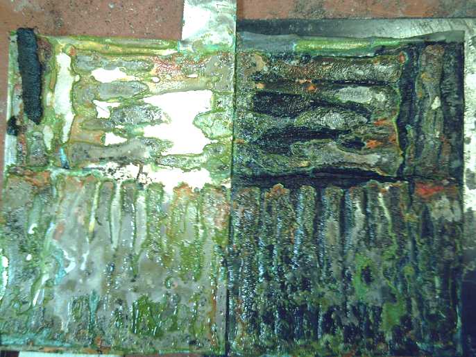 The cupro-nickel sheet after
usage (L), with
the NiOOH
The cupro-nickel sheet after
usage (L), with
the NiOOH
chunks electrode material on the separator paper (R)
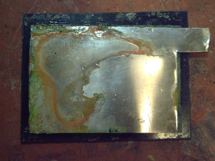 Some electrode material
substance made its way
around the back of the sheet.
Some electrode material
substance made its way
around the back of the sheet.
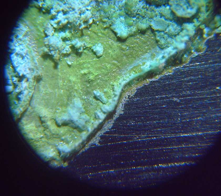 The cupro-nickel current
collector seemed to
almost bond with the nickel hydroxide electrode,
The cupro-nickel current
collector seemed to
almost bond with the nickel hydroxide electrode,
but it seemed virtually unaffected in areas where there was no
electrode substance.
It hadn't oxidized away after a couple of weeks of use, but seems
weaker where the terminal comes out.
I suspect more calcium oxide coating without missing any spots will
make it work.
[12th] Overnight it went down to 40mA, and rose to ~1.98V (charging
voltage was ~2.05, 1Ω resistor in series) and stayed over 1.7V for a
while off of charge. Discharge currents were around 670mA (1Ω load -
even 700mA short circuit).
Hmm... this might work. It might also keep up the strong
but gradually decreasing "self-discharge" for a week. Or the entire
piece of cupro-nickel (or the terminal stem) might corrode away to
nothing over time.
Well, I had to look. Mostly it seemed to only be corroding
where the electrode bits contacted it. It made some bright colors.
Another week may tell if it works well or not. Certainly the current
drive is improved over the graphite, which is probably related to
better contact through the expanded corrosion substance than to the
flat graphite surface.
By the end of the day a sort of equilibrium had been
reached. Charging current was around 40mA and the voltage 1.99.
Momentarily it would drive a 1Ω load to 700mA and a short circuit to
just over an amp. But the self discharge was fierce and had stopped
decreasing earlier in the day.
Could zinc dendrites have penetrated both separator sheets
and made a short? I opened the cell and stuck in another separator
sheet of thicker watercolor paper between the other two, and squirted
some salt electrolyte onto it, then closed it up again. The charging
current doubled, and so did the discharge current, to over 2 amps into
a short circuit. Not dendrites, then. (Yay!) Perhaps it had been
getting too dry? Further tests will have to wait until morning.
[13th] By morning it seemed to have improved a little. Charge current
was down from 80s to 60s mA and discharge into 1 Ω was over an amp -- 3
times what it had been with the gasket graphite. Short circuit
discharge was up to 2.85 amps. (Again momentary values that dropped
rapidly.) So I decided to leave it for a few more hours.
But it didn't seem to change much. I tried taking the
'trodes out and diluting impurities again, but instead of reducing
currents they increased again. But a couple of hours later it drove a
10 ohm load for almost 3 minutes (quitting when it hit 1.0 volts)
instead of 1-1/2. (All pretty pathetic, I know.)
New 'Positrode'
In the meantime I cut two more cupro-nickel current
collectors (in spite of still being rather in doubt about them) and
painted calcium oxide onto one face of each.
I still had the rest of the jar of "+trode" powders I had
made in July 2019.
(TENews #134 & #73) (IIRC I had added quite a bit of extra CCB or
graphite powder in #134. That might decrease amp-hours per kilogram,
but it
shouldn't stop it if it's going to work.)
Monel Powder - 16 g
Ni(OH)2 - 17 g
KMnO4 - 40 g
Graphite Powder - 5 g
Sm2O3 - 5 g
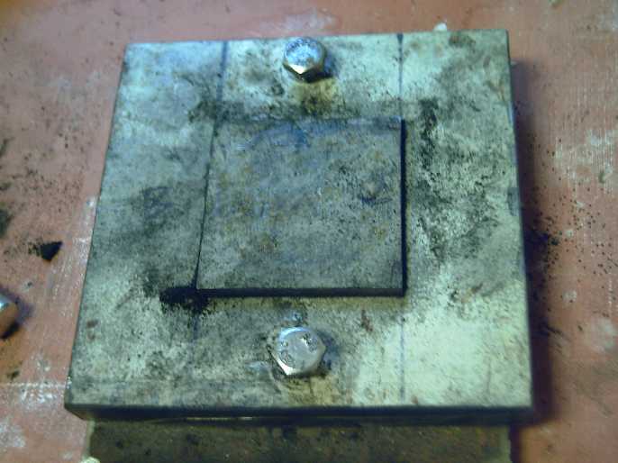 I got out the
50x50mm square electrode compactor I had
made 3 or 4 years ago. I had picked that smaller size before I thought
of making externally clamped cells so they wouldn't bulge. Now it was
too small and awkward for the present 65x90mm cell size, but it was
hard work to make and it worked, so I used it.
I got out the
50x50mm square electrode compactor I had
made 3 or 4 years ago. I had picked that smaller size before I thought
of making externally clamped cells so they wouldn't bulge. Now it was
too small and awkward for the present 65x90mm cell size, but it was
hard work to make and it worked, so I used it.
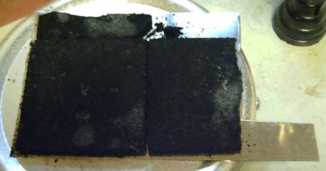 I mixed a very
small amount of dishsoap into
the powder
and compacted four squares of about 7.5 grams each with 1 ton of
pressure. (They all could have used a bit more liquid.) I dried them on
the hotplate and very briefly ran a low flame propane torch over them
to sinter them together a bit. They were still very brittle. One broke
up. I cut one to 3/4 wide in order to fit two onto one of the 65x90mm
current collectors, with 8.5 square centimeters left blank. I used the
other pieces for a second electrode.
I mixed a very
small amount of dishsoap into
the powder
and compacted four squares of about 7.5 grams each with 1 ton of
pressure. (They all could have used a bit more liquid.) I dried them on
the hotplate and very briefly ran a low flame propane torch over them
to sinter them together a bit. They were still very brittle. One broke
up. I cut one to 3/4 wide in order to fit two onto one of the 65x90mm
current collectors, with 8.5 square centimeters left blank. I used the
other pieces for a second electrode.
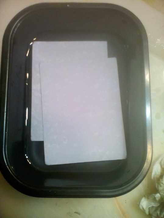 I also painted
two pieces of watercolor paper
with
dishsoap, zircon & electrolyte as separator sheets (Just one
separator sheet between the electrodes: dishsoap as gel; zircon to
raise hydrogen overvoltage for the zinc side). I left those to dry
first, and set about diluting the new electrodes in rain water, then
distilled water twice.
I also painted
two pieces of watercolor paper
with
dishsoap, zircon & electrolyte as separator sheets (Just one
separator sheet between the electrodes: dishsoap as gel; zircon to
raise hydrogen overvoltage for the zinc side). I left those to dry
first, and set about diluting the new electrodes in rain water, then
distilled water twice.
There was a problem. While
the bits of commercial dry cell
electrode had held together fine, mine first tried to float off the
metal sheet, then they swelled up and crumbled. Before the rinse:
promising looking compacted powders electrode. After the rinse: sludge.
It seemed like I needed some "glue" or something.
Carboxymethylcellulose or Veegum or something. Or they needed to be
encased. The "pocket electrode" idea rears its ugly head again.
Well, maybe I'll just put the cupro-nickel into the cell,
pour the sludge on top and even it out, and slap a separator sheet with
gel on top of that, then a zinc electrode. If the external clamp
provides the pressure perhaps the 'sludge' will compact to where the
particles connect electricly again and the cell will work?
As I think about it, maybe the bath in water is just what
it needs to get the reaction going, to turn the Ni(OH)2 and the KMnO4
into nickel manganates?
Once I have a cell with all my own 'trodes working
properly I
can go back to worrying about details like starting with an even charge
in both electrodes and sealing the cell so water doesn't escape and
gradually deteriorate the
performance to nothing.
[14th] Back to the first cell... Overnight the self discharge/charge
current had dropped to 50mA. Disconnected it took 90 seconds to drop
below 1.8V, and it drove the 10Ω load for just over 4 minutes. Then if
allowed to recover a while (very slowly - 10 minutes?), for much of
another minute.
I wondered again how much of the self discharge was from
oxygen entering the cell, and I covered the terminal holes as best I
could with modeling clay. That may have helped marginally. But there
still could be enough air getting in somewhere to keep it well
oxygenated inside.
Around noon I tried testing it again. The charge current
hadn't dropped: 65mA. But it stayed above 1.8 volts for about 90
seconds again. Then a 10Ω load test stayed above 1.6 volts longer (35
s.) and it ran for 5 minutes instead of 4 (down to 1.0V), so no sort of
equilibrium seems to have set in. The voltages jump up and down a bit
as if making and breaking connections inside the cell, and apparently
more of the electrode bits are being employed. Still it should run far
longer to be a real battery. I left it sitting a while and it recovered
to ~1.60 volts... and sat there... dropping only a millivolt every few
minutes. Apparently the self discharge is much reduced after all. It
still isn't 0, but it's down to where it may be explained by trace
impurities in the salt and a bit of air getting in. Maybe it's a
battery after all!
In the evening I did another 10Ω load test. Again it ran
for 5 minutes, and had recovered to about 1.555V when I looked. I then
ran the load test again, without recharging. It lasted another 2
minutes, and recovered to 1.545V. At that point I went for a third run,
of one minute, recovering to 1.541V. (All almost exactly even minutes.)
A fourth run went another 50 seconds. At this point it was almost 9
minutes total, and could surely make it to 10 with a couple more runs.
At 1.2V and 120mA for 1/6 of and hour, that's 20mAH. Well, not much,
but not trivial anyway. I'm sure it's capable of much more. The zinc is
solid. I can't help but think I'm not getting much mileage out of the
bits of nickel electrode from the dry cell.
(pH is about 13. According to the Pourbaix diagrams, zinc should be
-1.2 volts and NiOOH +.6, so the cell should be 1.8 volts. We all know
it depends on the state of charge and that it'll drop with a load on
it. NiZn cells are usually rated 1.6V nominal, but it seems to me in
salt electrolyte the voltage is a little higher -- so call it nominal
1.7? Just might make 12V with 7 cells instead of 8?)
Now I wanted to try the new positrode, but I didn't want
to change the existing cell without more tests on it. I had cut the
front and back for a second cell when I did the first - now to finish
it. I'm estimating the substance might effectively be around 200
amp-hours per Kg. (NiOOH electrodes in practice might be 100, if that.
MnO2
is a theoretical 316, but doesn't recharge well. Nickel manganates is
another
wild card, but that's my estimate until I learn differently. The amp
capacity should be substantially higher than for NiOOH, too.) So 35 g
might be 7 amp-hours (which will have to be matched by a thicker zinc
plating) and instead of a few amps, tens of amps. With 2 faces on the
zinc and 2 NixMn(3-x)Oy
(or is it NixMn(3-x)(OH)2*y?)
positrodes, 14 amp-hours.
Anyway, there's the hope.
[15th] In the morning the charge current was down below 50mA. I tried
another load test. Not quite as good as yesterday. Perhaps the water is
drying out? Anyway, if it's not going to keep getting better bit by
bit... I changed my mind and decided to put the new
NixMn(3-x)Oz
plus side in the existing cell. Preparatory to that I did a discharge,
just so the zinc would have some little way to charge to, on the
assumption the the new electrode would need at least some charging
(notwithstanding the original "overcharged" permanganate valence).
I got to it in the evening. I cleaned out the case and put
the new "cracked-up slush" electrode into it. I pressed down pretty
hard but (to my surprise) I couldn't seem to compress it to any degree.
I got a cleaned, impregnated separator sheet and wetted it
down thoroughly with electrolyte, then pressed it in on top of the
electrode. It was a bit big and the sides folded up a little. That
seemed fine.
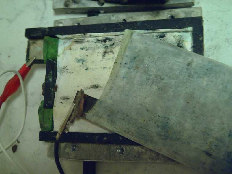 I put the zinc
electrode on top of that. I left it with
its original separator paper in addition to the new one. The worst it
could do was reduce currents a bit, and I didn't want to disturb
whatever was happening beneath it.
I put the zinc
electrode on top of that. I left it with
its original separator paper in addition to the new one. The worst it
could do was reduce currents a bit, and I didn't want to disturb
whatever was happening beneath it.
The materials seemed to pretty much fill the space. This
time there was no room for a spacer piece behind the zinc - or for a
second nickel electrode to double the capacity. Apparently the
"complete" cells would have to have wider walls. But I did worry it
would be just a little loose and leave room for the positrode to expand
a bit and lose conductivity.
Later I thought I should have added more electrolyte to
wet the positrode well as well as the separator paper. (I may soon
squirt some more into the tiny filler hole.)
 I thought I could cut a piece of
an inner tube so the
rubber fit around the edges to make a relatively waterproof seal. I
looked in the shop shelves and found instead a small roll of flat
rubber stock, 1.2mm thick. Even better! Then I thought, why cut it out
around the edges? Why not just a big square piece to fit across the
whole front and over the edges? And then: why have the plastic front at
all? Why not just have the rubber as the front, since it would be
clamped closed by the alume sandwich anyway? Certainly ideal for
testing and reopening, but might that even be good for a production
version? No need to glue the front on to try to keep it from leaking.
(Why did I take the picture and then rinse it off?)
I thought I could cut a piece of
an inner tube so the
rubber fit around the edges to make a relatively waterproof seal. I
looked in the shop shelves and found instead a small roll of flat
rubber stock, 1.2mm thick. Even better! Then I thought, why cut it out
around the edges? Why not just a big square piece to fit across the
whole front and over the edges? And then: why have the plastic front at
all? Why not just have the rubber as the front, since it would be
clamped closed by the alume sandwich anyway? Certainly ideal for
testing and reopening, but might that even be good for a production
version? No need to glue the front on to try to keep it from leaking.
(Why did I take the picture and then rinse it off?)
The half-new cell started out at only about .6V. I decided
to charge slowly and used a ten ohm resistor to the 2.05V power supply.
At 65mA the voltage rose immediately to ~1.2V and in 20 minutes to 1.7,
dropping under 40mA. It seemed much more promising than my last try at
a nickel-manganates electrode, where (as best I recall) the cell kept
wanting to drop to 1.3V. Maybe the water bath after compacting
facilitated reactions between the nickel and the permanganate? Time to
leave it for a couple of hours to charge. By bedtime it seemed apparent
that things were working, but that it would be many days before it
started to look like a battery.
[16th] Aside from adding another 3cc or
so of electrolyte, it looked
like there would be little point doing anything with the cell this day
- probably not for two or three days. Voltage on charge had risen
overnight to 1.81. Adding the water dropped it to 1.67, so it must have
needed it. Off charge the voltage fell rapidly, but more slowly than
the previous evening. For no known reason, I feel the whole process has
to be done very slowly to give the best result. The changes to the
current collector sheet say that a lot is happening in there, and
surely converting Ni(OH)2 + KMnO4 to
NixMn(3-x)Oy
is a whole process (which I only trust is happening somewhere in
between having wetted it and charging and maybe discharging it.)
Purifying sodium dodecylbenzene sulfonate from Sunlight dishsoap?
I looked on line for the sulfonate. Westlab didn't have
it, ACP Chemicals where I had purchased chemicals before was gone from
Canada, Alfa Aesar (USA) had sulfonates (that might work) but not
that exact one. Sigma Aldrich (Ontario) had it. But my experience with
them has
been "don't bother". They seem to be part of Fischer Scientific now,
who as I recall had a minimum order of 500$ back in 2010 or so. It
could be 1000$
today. But my brother Stuart had worked in biochemical research. Did he
know of another source or have an "in" with Sigma Aldrich? I phoned
him. Nope.
I joked about "purifying" the Sunlight - eliminating the
other 70 or 80 or 90% of it that was "impurities". He said I could try
"fractional crystalization". If the substance was cooled and allowed to
dry out, the different ingredients might crystalize out of the solution
at different times and at different rates, starting with the least
soluble... which should be the sulfonate. He said he had had the soap
from laundry detergent crystalize out of the liquid and a cold room,
and wondered why it looked thin and wasn't getting his clothes clean.
He found the crystals on the bottom in the container. (They just might
have been sulfonates!) He said to do it slowly to get big crystals.
(And to think, I was only joking -- I had thought "purifying" it was a
hopeless idea!) I don't know how related that was to his biochemistry,
but it sounded like a great thing to try!
I poured out four open petri dishes and put one in a cool place, one in
the fridge, one in the window greenhouse where it was about freezing
(frost outside this evening), and one in the freezers. Next: see how
long until I spill one... er, I mean, wait for results. if any.
[17th] After rising gradually through the 1.7's volts range all day
yesterday, the cell hit 1.812V this morning. Apparently something is
happening.
The dishsoap in the fridge and 'outside' at about freezing
temperature seemed unchanged, but that in the freezer had become hard,
like a solid wax. I decided to leave it in longer and see if anything
happened.
[18th] Hmm... after another whole day the cell is still fighting the
war of 1812. Why? I opened the cell and discovered it was quite dry
inside. I don't think there were any appreciable leaks, so the
reactions had to be using it up. That seemed quite reasonable given
that the nickel manganates in water were probably of the form
"NixMn(3-x)(OH)2*y" rather than
"NixMn(3-x)Oy"
And it didn't seem there were salt crystals
solidified out of solution, so they may have been using up salt too.
Perhaps some of the green color seen earlier was copper or nickel
chloride?
I added a few squirts of water and closed it up again.
The Best Cell Construction! (Especially for experimental cells!)
Here I will remark that this cell is absolutely the best
construction. It has the ABS plastic back and edges in which to lay
everything, one layer at a time, then the rubber sheet covering the
front
and sealing all around the edges, and the external alume clamp plates
to hold it all together and prevent the powder electrode from swelling
into a sponge that doesn't conduct electricity. For a test cell, some
bits of modeling clay can cover the openings where the terminals come
out. (Bee's wax or ??? for a "production" cell.)
Opening the cell is simple: undo 4 machine screws and pull the rubber
off. The zinc plated copper electrode at the front also comes out
freely to expose the lower layers.
The external clamp set was probably the best idea I've had
on this project, and it enabled the simple "no glue" rubber cover.
[19th] I opened it again and again it was pretty dry inside. I'm still
convinced - so far - that something is happening in there (probably the
formation of the nickel manganates from the Ni(OH)2 and KMnO4), that
whatever it is it uses up the electrolyte, and that eventually the
process will finish. This time instead of just wetting the separator
paper I gave it about 5cc of water to where it was threatening to
actually spill out the lowest edge. (I have it slightly tilted up so
the terminal openings are about even with the bottom edge to try and
keep the terminals dry... I have more rusted out alligator clips from
salty, damp "+" terminals than ...whatever! I suppose that if the
rubber is truly sealing the edges I should be able to stand it up
vertical without issue.) The voltage dropped down to 1.3 or so
and about 70mA charge current through the 10Ω from 2.05V.
Okay, it doesn't seem to be working. Nickel manganates
holds such promise. There must be something else that's needed
chemicly, rather than expecting the right reactions to occur electricly
by charging to "form" the electrode.
Well, first, I decided to put a spacer in behind the zinc
'trode and crank down on the screws. After all, the powders had swelled
up in the water when I rinsed the compacted positive. maybe it was
suffering from poor conductivity? I tightened it up and all the
pressure was now compacting the insides, because a drip of water came
out the lower corner so it wasn't compacting the rubber seal. I swapped
to the 1Ω resistor and the voltage shot up from 1.4 to 1.9V, and
because of the higher voltage the current was only 100mA where it had
been 60 with the 10Ω. Soon it was up to 1.96V and the current down to
the same 60mA. Maybe compacting; maybe more charge current? Anything
else before I start spraying miscellaneous chemicals on that electrode
and seeing what happens? I guess at almost 2 volts now, I should see
what happens with a few more hours of charging.
It ran a 20Ω load down to 1V in 4 minutes, then repeating
a while later, 6 minutes.
[20th] The 20Ω load ran it down to 1V in 5-1/2 minutes, but just 1/2
hour later it lasted 8 minutes. As usual it took minutes to recover to
just 1.25V. I put in a couple more cc of electrolyte, some of which
promptly leaked out the bottom and some came up through the terminal
holes. (Some stayed, I think.) It seemed that without the thin plastic
spacer sheet there wasn't enough pressure on the electrode, and with it
I couldn't quite get the edges to seal. Apparently I need more finely
graduated spacers! I upped the charge voltage to about 2.10V, still
through the 1Ω resistor. Cell voltage soon rose to just over 2 volts.
Momentary short circuit current was only 2-3/4 amps.
Wait! The leaked electrolyte looked murky. Was it suspended particles,
or dissolved matter? Also the voltage went down and the current up. I
disassembled the cell. The NiMn powders 'trode mostly didn't stick to
the separator sheet. I picked it up by the current collector beneath
and put it in distilled water, which took on a brown color. It seemed
the electrolyte had become contaminated with something. Also powder
freely washed off the electrode as before.
The drop in voltage was probably zinc dendrites. For the
moment I can change separator pads to eliminate dendrites while I
experiment with positive electrodes. (How do I get the sulfonate out of
the dishsoap to impregnate a separator pad with it?) I set the
electrode on a paper towel to soak out most of the water. I set
everything apart and left it to dry.
I've been assuming that most of the reactions to get the
substances into the desired forms would be electrochemical and would
occur with charging and discharging the cell. Or is that just wishful
thinking? It seems to be taking geologic time. I found out little about
nickel manganates on line before, but it never hurts to go look again.
Different search terms, different search engine... This time there was
a glimmer of illumination from what was shown of a 2010 research paper
from Argentina behind a pay wall, that indicated I should try forming
nickel manganates with the steps in a different order.
1) Soak the electrode or just the unprocessed powders in distilled
water. (The electrode swells up into sludge anyway!) This may hydrate
and put together the KMnO4 and the Ni(OH)2 to yield things along the
lines of nickel permanganate, Ni(MnO4)2 + 2(KOH). Nickel permanganate
was the starting substance in the paper. (What temperature for
the water? Cold? Might work better or faster in hot?)
2) Compress the resulting electrode paste/powders [instead of the
initial powders] into a "brick(s)" and put it (or the pieces) onto the
current collector sheet.
3) Dry this and then torch it with the propane torch to "calcine" the
water-reacted mixture rather than the initial "raw" mixture. Then
assemble the cell.
The mixture may (or may not) then be along the lines of: NiMn2O(4+?)
, which may hydrate to NiMn2(OH)(8+2?) in the
cell, or partially hydrate to some being "OH"es. Valence changes
apparently occur as Ni and Mn trade places in the spinel crystalline
lattice, Resulting in more or fewer "O--" or "OH-" components in the
substance, or maybe "OH"es become "O"s and vise versa (as with Ni OH OH
[nickel valence 2] charging to Ni O OH [valence 3]). And of course
other related molecules will probably occur in my haphazard substance
in many and various places, such as Ni2Mn(O4+?) .
It's all still guesswork. What water temperature and for
how long? Could one (as I suspect) torch it too much and turn it into a
non-conductive ceramic (not to mention burning out or modifying the
graphite or CCB)? Do the reactions I'm supposing happen at all? Does it
even work anything like how I've been thinking it should once it's made?
[21st] I raised the voltage to 2.11V, and the performance is
considerably improved after 4 hours. Could it be I haven't had it high
enough? I think I'll try 2.2V. Yep. The voltages are staying
substantially higher for longer when the charge is off and when driving
a 20Ω load. One just ended at 1.25V after 6.1 minutes instead of 1.0V.
A couple of hours later, the next one ran 8.0 minutes down to 1.30V.
It's improving just like I thought it should! I was charging at a
little too low a voltage. The nickel-manganates & zinc cell in salt
electrolyte is apparently closer to 2 volts than 1.8, so it needs to be
charged at substantially over 2 volts. (One can also try and charge a
car battery at 12 volts but it won't get much charged - 13.3 volts or
more instead makes all the difference!)
Going up... I set it to 2.289V. (The power supply doesn't
adjust very fine. That was as close as I could get to 2.300V.) And why
not? I had the nickel manganates + manganese cells charging at 2.7V or
so ten years ago, and zinc is only about .3 volts lower than metallic
manganese.
Again what an advantage it is to be able to easily open
and dissect the cell, and replace individual components! Previously I
think the positrodes were gradually improving until zinc dendrites
wrecked things and I'd have to start over. Now I can replace the
separator sheet and remove them. The zinc 'trodes can now be dealt with
separately once I know the other is working well. (Then I can buy or
isolate the sodium dodecylbenzenesulfonate ion transfer substance. or
PVA or other gell.) How can I have not done something about this years
ago?
Next run: 13.0 minutes down to 1.111 volts. (Oops, I
forgot about it! Still using 20Ω.) And momentary short circuit current
"charged" rose a
little to 3.5 amps. I put it back on 10Ω charge instead of 1Ω, thinking
not to push it too hard overnight.
[22nd] With the reduced charge the voltage dropped and it didn't get
back up to 2.0V overnight. I left it running.
I decided to make one more cell similar to this one. The
plastic was cut; I had the second electrode. I played the torch lightly
over the electrode. It didn't seem like much and the current collector
sheet was still cool, but I carried it into the house and noticed a
couple of puffs of smoke come off it, and the sheet had become warm. So
I'll presume the porous electrode got about the right amount of
calcining. (Later I decided to just use this new electrode in the same
cell when I got the new salt. New cells would be the larger size.)
New Cell Size: Largest Old Cell Size
Why did I only want to make one more cell this size? With
the little dangerous amount of knowledge I've collected over the years
and this month I'm back to dreaming that everything is going to work
soon and thinking about practical battery construction. I had at some
previous point picked the same width as I using now but with cells 6
inches tall. But it was hard shoving the assembly in through the top of
a tall, thin cell that had a front and a back already glued onto it.
And since the positrodes bulged out once wetted and the cells hardly
worked, I had shrunk the whole idea to just 50x50mm electrodes. But now
the rubber front doesn't go on until the insides are in place and the
external plates clamp now prevents bulging so "any" size could work and
I can think of larger sizes again.
The 65mm electrode width is about the widest practical for
my jewelers rolling mill, and I'm rolling the coarse plated zinc to
squash it into decent flat sheets on the copper foil. Furthermore, 1/4
inch thick alume plates might themselves bulge if the cell, externally
85mm, is much wider. Multiple bolts can go along the sides if it's
taller.
The 6 inch / 150mm height just seems like a practical
place to stop. The electrodes will be about 65*130mm or 84.5
sq.cm. 70*135mm or 94.5 sq.cm. At 100mA/sq.cm that would make
for over 9 amps current per electrode pair. (not that it's been that
high so far, but it should be.) Capacity should be ten amp-hours or
maybe 17 or 18 nominal watt-hours. (And I already have the zinc plating
jar setup for that size.)
I will want to go to at least a double sided zinced sheet
facing two nickel manganates positives. More plates such as two double
zincs facing four NiMn's are also possible, multiplying capacity per
cell.(One cupro-nickel current collector could be the base for a
two-face NiMn 'trode as well. Hmm... it's easiest to keep the crumbly
electrode side up on its metal "spatula". How is a two-face one - or
even just 'the' top one - going to work for assembly?)
I'll keep the format of one-piece sheet current collectors
with terminal tabs. With metal sheets the tabs should be flexible but
strong enough to take some handling during assembly and use. I'll make
them long enough to bend to a desired position. First, if there are two
NiMn electrodes in a cell they'll each have an external terminal and
need to be tied together. Then, there's a big advantage in ease of use
if the terminals in adjacent cells in the clamp can be bent over a bit
to touch each other. Then a single bolt through a hole in the tab can
easily tie cells together in series.
[23rd] Again with only a small charge current, the voltage hadn't risen
overnight, sitting at about 1.950V. It seemed to have arrived at some
balance between charge and self discharge. I opened it and saw some
green from the lower electrode on the top of the separator paper. Could
it be that or zinc dendrites through the sheet?
I decided to replace the sheet again. This time the cell
was open for some time (15 minutes?) as I cut a piece then rinsed it in
case there were any soluble impurities that should be removed. When I
put it back together, the voltage was way lower, like 1.2 or 1.3 volts
- maybe less. (Dang, I had been puzzled by lower voltages after opening
the cell before, too. This time was simply worse.) I had thought that
air might cause gradual self discharge. Now it seemed as if a whole
electrode had been substantially discharged just by being in air for a
short time. There, surely, was the real self discharge problem! I knew
it was leaking around the edges. I took out the spacer that seemed to
have been wedging it slightly open and put in a smaller one. I closed
it back up and squirted in a couple of cc's of water. This time none
leaked out the bottom. I closed up the spaces around the terminals with
modeling clay as best I could.
And put it back on high charge (1Ω @ 2.3V). In a few hours
it dropped to the lowest charge current yet with 1Ω & 2.3V: 49mA,
and there it stayed. A 20Ω load test ran for 11.75 minutes down to
1.200V. Best run yet. I'm starting to think that the nickel manganates
positive is working just fine. It seems to me these cells could be just
fine and suffer from 3 known or suspected problems:
1) Air (the oxygen) getting in seems to spontaneously discharge the
zinc, presumably 2 Zn + O2 => 2 ZnO. This is probably the worst of
it.
2) Possibly the salt has an impurity (eg, a nitrate), and diluting the
salt out and replacing with... more potentially contaminated salt... is
surely a losing proposition.
3) In recharging, the zinc can form dendrites which (if nothing else)
can cause sort circuits through the separator sheet.
I'm sure zinc dendrites have ended many of my test cells
prematurely. In the present one I can replace the separator sheet and
'fix' it to keep using it. I'm certain the ion transfer gel is the key
to stopping dendrites. (I can try the PVA again, but I may just have to
bite the bullet and order some sodium dodecylbenzenesulfonate from
Sigma-Aldrich.)
(Later: I started becoming more and more convinced that impurities in
the "99.9% KCl" have been my most persistent problem all these years.
NaCl from the store has iodine, and iodine will jump from I2
to I3 (or is it I3- ion?) and (I'm
sure) cause self discharge. (It may (or may not) also be in the form
KI, which might (or might not) also be a problem. I can't imagine sea
salt working well.) Suddenly this gives me a glimmer of why, if I'm
remembering correctly, my cells sometimes seemed to work when I used
KOH but then kept self discharging when I switched to salt: the KOH was
pure but the KCl was contaminated!
I ordered 1Kg of KCl salt from Westlab. Sigh, 75$ for what
cost me a few bucks at the health food store a few years ago, but now
I'm more than dubious about that .1% impurity. Maybe what I got at the
health food store was about the worst money I ever spent - has kept me
in the dark for years! (R/G... How many '9's purity is that? It didn't
even say. But I think R/G, "reagent grade", means the very purest.)
Here's an easy way I can check to see what effect air has
in the cell: charge it until the voltage stops rising and the current
stops dropping, and then unplug the modeling clay from the terminal
holes. If the air is causing discharge, the voltage should drop and the
current rise.
Okay, sealed as best I can: with 10Ω charge it's sitting
at 1.995-1.999V and 28.x mA, the lowest it has been. No electrolyte
drips out even if I tip it on one side. On removing the modeling clay,
electrolyte leaks out if I tip it over. (And the electrolyte has that
brown tinge again.) As an immediate or rapid effect (a few minutes), it
only dropped to about 1.990 volts and the current rose to 29+mA. It
doesn't seem like much. And then it rose to 1.996 again. I'm thinking
that opening the cell and pulling out the electrode discharged it
quickly with the whole plate exposed to the air, but inside the cell it
doesn't seem like a big effect. I've already diluted out any soluble
impurities in the electrodes and the separator paper - to some effect
but not totally solving the problem. Therefore I'm suspecting impure
salt is the chief culprit in the gradual self discharge. I suspect I'll
find out when I get the new salt from the chemical company.
If that proves to be the case, then all this time the
problem has been soluble impurities - first in the electrodes, then
also the electrolyte itself. In retrospect, it all makes sense. To
prove (or disprove) it, I'm now waiting for the salt.
[24th] I had coffee with
someone and mentioned the salt. He suggested I
needed to make my own.
In about 2 seconds that clicked: HCl + KOH => KCl + H2O ! Duh! Some
chemist I am - never thought of it. My KOH is USP grade, but the acid
is just hardware store variety. Still, maybe it would give better
results than my present KCl? 30cc of acid. After enough little spoons
of KOH flakes, the green HCl acid turned brown and the pH jumped
suddenly from 1 to 13. Much salt, being less soluble than either of the
others, settled out on the bottom. Still 30cc. A few flakes (of?)
floated on top, and I scooped them out. It settled to some pretty clear
looking water, and on the bottom some things that looked like salt
crystals sitting on top of some brown scunge. My already small
confidence in the purity of the acid took a nose dive.
Nevertheless, then I took the cell apart and diluted it in
distilled water, 3 times, drip-dry onto a paper towel after each. I
dripped some of the new salt water into the cell and tried charging it.
The current was just a little lower, and when the charge was
disconnected, there was that same neverending drop - drop - drop -
drop, a millivolt at a time, maybe a little slower but never finding a
stable point at any voltage until a very low level.
After a while on 10Ω charge the voltage rose over 2.0V and
the current was the lowest yet, about 25mA. Again it suggests that
there was a slight improvement, which suggests that changing the salt
made a difference.
But it wasn't a cure. I should probably just await the
salt from Westlab before I go farther on this. I do anticipate success.
I suspect at this point that my batteries have all along been much
better than I thought, but that the impurity in the salt has been
preventing them from charging and holding a charge properly.
So instead I cut pieces and
made an 85mm * 150mm * 13mm
O.D. cell body. Inside will be 70mm * 135mm * 10mm with just a bit of
"wiggle room" around the edges of the electrodes. That's 94.5 sq.cm
electrodes. (Dang, how did I get and other ".5" in there? And how did I
get so close to 100sq.cm without being there?) Anyway at 100mA/sq.cm
and double electrodes, that's almost 20 amps. And I bet when the salt
is good and the electrodes can get fully charged, it'll be higher than
100.
I cut two cupro-nickel current collectors to fit.
[25th] Overnight 10Ω charge had gone to 2.04V & 22mA or so. That's
the lowest current yet, and it dropped more slowly when taken off
charge. As the salt is from a different source, it seems to be further
confirmation that the salt is to blame for the self discharge. But that
this one is by no means pure either.
[28th] I started on a "full size" cell complete with doing a battery
making video about it a couple of days ago. I cut pieces and glued
together a case and cut a front rubber piece, and I cut a cupro-nickel
current collector to fit. Today I cut a copper current collector, which
weighed 11.45g, and did some zinc plating. I made it just a bit smaller
(68 x 133mm) so I could easily wrap the thick separator paper around it
and still insert it into the cell easily.
I modified the ABS plating holder that holds the copper
foil sheet between the two zinc sheets so that water could flow better
and I put feet under it to hold it up and leave a space under the
bottom. That way I could, and did, put the whole plating jar on the
magnetic stirrer to hopefully get more even plating across the copper
surfaces. I think it helped quite a bit.
I plated at about 3.0A, which occurred at around .79V. I
inspected after 1/2 hour, 1 hour and 2 hours. At 2 it looked rough
enough that I brushed it off with a toothbrush and then ran it through
the jewelers rolling mill until it felt smoother, but not with any
notable pressure. It weighed 19.6 grams, so it had just over 8 grams of
zinc plating, theoreticly about 6.6 amp-hours. This almost agrees with
2 hours of plating at 3 amps, but at first I wasn't timing it or
regulating the current carefully - it was over 3 amps for a while. I
decided to go for about 10 amp-hours. After another hour and a bit I
ended it, scrubbed it off with a toothbrush and ran it through the
rolling mill to squash down the rough surface. One side looked very
nice and was pretty smooth after the mill, the other was a bit blotchy
but should do. It weighed 24.45 grams, so exactly 13 grams of zinc were
plated on; 10.66 theoretical amp-hours. I put it away in a ziplock back
in a dark place (drawer) hoping none turns to carbonate from exposure
to CO2 in the air. (Some still might oxidize to ZnO & zinc oxide
has photosensitive properties.)
[29th] AWG! My brother tells me that R/G, reagent grade, is the WORST,
not the BEST! It was the ONLY choice at Westlab. It could be worse than
the KCl from the health food store! He also said if I dissolved some
salt in hot water, then let it gradually evaporate and form crystals,
that the crystals should be pretty pure. The slower the evaporation,
the larger the crystals, to be picked out with tweezers. Hopefully
crystals of impurities will have different color and or shape than KCl
crystals. And that the salt crystals are an awful lot bigger than most
salt crystals!
I went into town and checked the mail. Salt hadn't come.
(Nor any of the things I ordered earlier from AliExpress. No doubt they
will all show up on the same day, someday.)
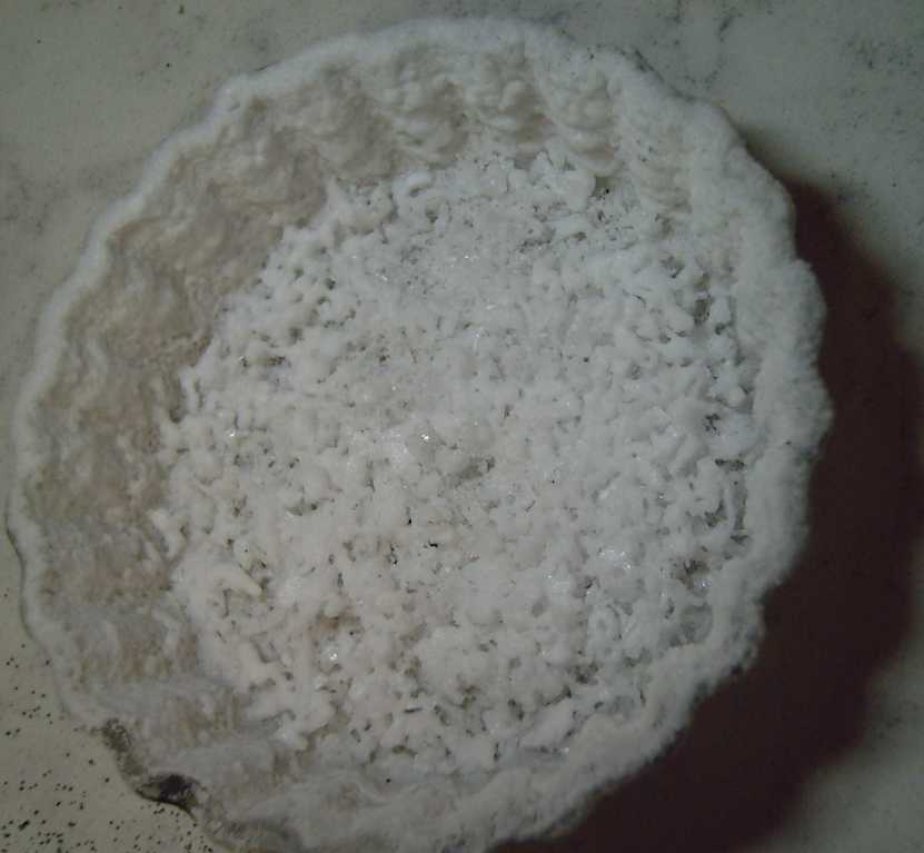 I dumped some
salt in distilled water in a 250cc beaker and put it on the lab
hotplate, and set it to keep it warm. (I don't want to wait over
Christmass for the water to evaporate!) Then I moved it to a grill on
the woodstove. Then I poured some into a clean ashtray. The ashtray
evaporated quickly and left a clump of stuck-together crystals. (I
suspect the ones that came out first around the side walls are the
purest.)
I dumped some
salt in distilled water in a 250cc beaker and put it on the lab
hotplate, and set it to keep it warm. (I don't want to wait over
Christmass for the water to evaporate!) Then I moved it to a grill on
the woodstove. Then I poured some into a clean ashtray. The ashtray
evaporated quickly and left a clump of stuck-together crystals. (I
suspect the ones that came out first around the side walls are the
purest.)
I put the recently made ([20th], above) electrode into the
cell, then a new separator paper, and dripped some distilled woter onto
it. I took a few of the salt crystals from the ashtray with tweezers
and dropped them into the drips. Then I put on the zinc electrode.
There was hardly any current. I put in a "too fat" spacer and with the
alume clamp piece on the outsides, pressed the whole cell to 1/2 ton. I
brought it back in and tried again. This time it worked much better.
The current was still a bit low and I dripped in some more water, which
brought it up over 40mA through 10Ω. With a charge voltage of 2.188V
(no fine adjust!), in a few minutes it was down to 36.6mA at 1.812V.
There I left it for 3/4 hour. By then the current was up to 42mA and
voltage down to 1.74V. The water has probably distributed itself more
evenly throughout the cell. I'll leave it on overnight.
[30th] In the morning the voltage had risen to 1.84, at 33mA. I added
some water. So far not much different from other tries. Then it started
dropping. At the end of the afternoon I replaced the separator sheet,
wetting it with a bit of distilled water and a few more salt crystals.
The voltage jumped up to almost the charge voltage with a current of
only about 10mA. I left it charging at 30mA, 2.15V, through 1Ω.
[Dec. 1st]
A couple of days later the voltage was dropping again. I thought of the
blotches on the removed separators and started thinking bits of the "+"
powders - even tho they shouldn't be dissolving - must be seeping
through the pores in the paper. Were they just too coarse? I wrapped a
piece of cellophane around the paper. The voltage went up again and the
current down. I'm more and more sure I essentially have a good battery.
Somewhere here I hope and expect there must be a bottom to these
problems.
If there is, there's still one more hurdle and that's to
get the zinc ions to not migrate during charge and discharge. That's
where all the other attempted battery developers have come up blank.
I'm hoping for the sodium dodecylbenzene sulfonate. (The PVA might work
too.)
[Dec. 2nd] The cellophane seemed to stop the leakage as the voltage
dropped very slowly (but still kept dropping). But the cell didn't seem
to hold any charge to speak of. With a 20Ω load it would drop to 1.25V
in a minute.
On a hunch I got out a new separator sheet and painted it
with varsol. I let that evaporate and then wetted it and smeared on a
little salt. This time I just threw in a sheet of zinc for a negative.
I wanted to see if the plus side was staying charged and if the varsol
would block the pores so no powder from it would seep through. Well, I
guess the "+" wasn't charged to start with. The cell had to start up
from "not much" again as usual, while metallic zinc is already
charged. Current started at just 3mA through 1Ω with the cell voltage
hardly below the charge voltage. Gradually the current crept up by
maybe about .6mA/minute, and the voltage went down correspondingly.
[Dec. 5th] After 3 days of good results from the cell, it would seem
that the Varsol treatment worked! (I had wanted to use toluene - methyl
benzene. My can of it that I had brought with me when I moved here had
rusted through and it had evaporated, and I can't buy any on this
island.)
My
Solar
Power
System
The Usual Daily/Monthly/Yearly Log of Solar
Power Generated [and grid power consumed]
(All times are in PST: clock 48 minutes ahead of local sun time, not
PDT which
is an hour and 48 minutes ahead. (DC) battery system power output
readings are reset to zero
daily (often just for LED lights, occasionally used with other loads:
Chevy Sprint electric car, inverters in power outages or other 36V
loads), while the
grid tied readings are cumulative.)
Daily Figures
Notes: House Main meter (6 digits) accumulates. DC meter now
accumulates until it loses precision (9.999 WH => 0010 KWH), then is
reset. House East and Cabin meters (4
digits) are reset to 0 when they get near 99.99 (which goes to "100.0")
- owing to loss of second decimal precision.
New Order of Daily Solar Readings (Beginning May 2022):
Date House, House, House, Cabin => Total KWH Solar [Notable
power
Usages; Grid power meter@time] Sky/weather conditions
Main
DC East
October
31st 4113.40, 7.67, 12.68, 35.15 => 5.47 [35Km;
733@17:30] Some sun, some clouds, rain. 3° - down from 7°+
until today.
Perry's RV is still parked in my cabin. Near the end of October he
plugged in some electric heater and total daily power consumption has
doubled. (He was supposed to have removed the RV by the end of
September.
Then mid October. I wanted to finish at least one more wall this fall
and it's in the way! Now it's too cold, wet and windy out. He came and
turned down the heater on the 14th.) He pulled it out from the building
part way (it leaks at the back) and made at least a bit of room inside.
I put in my decaying gyproc and plywood, which had been theoreticly
under metal roof pieces, but somehow there was usually some path water
was running in.
November
01st 4116.57, 7.79, 16.30, 37.28 => 9.04 [55Km; 791@17:30] Mostly
sunny. (Maybe all day except earlier AM.) 0 to 3°.
02d 4117.87, 7.97, 17.10, 37.93 => 2.93 [851@17:00] Clouds.
1°. Brr!
03rd 4119.10, 8.10, 18.37, 38.70 => 3.40 [914@17:30] Cloudy. A bit
warmer.
04th 4121.54, 8.21, 20.44, 39.90 => 5.82 [90Km; 983@17:30] similar
05th 4122.42, 8.35, 21.63, 40.28 => 2.59 [1047@17:30] Snow AM. 1°
06th 4125.14, 8.49, 24.61, 42.05 => 7.61 [60Km; 1101@17:30] Some
sun.
No
rain or snow. cold. Afternoon losing time has finally ended thank God!
For a few weeks, anyway.
07th 4125.46, 8.70, 24.72, 42.31 => .90 [1164@17:00] Clouds.
Frozen. What happened to the carport panels? Light is out on one. There
were two brief power failures today. Must investigate tomorrow! (Seemed
nothing was wrong. Maybe the "700W" microinverters aren't good in low
light?)
08th 4127.25, 8.90, 25.99, 43.22 => 4.17 [55Km; 1238@17:30]
09th 4129.18, 9.07, 27.41, 44.35 => 4.65 [1304@17:00] -2° brrr
10th 4129.20, 9.18, 27.43, 44.41 => .21 [55Km;
1368@17:00] +7° strong wind & 3 hr. power fail in PM.
11th 4132.83, 9.30, 30.07, 46.50 => 8.48 [90Km; 1440@17:00] Sunny
until mid afternoon. Frost AM, +1 to 6°.
12th 4133.73, 9.40, 30.41, 46.90 => 1.74 [60Km; 1510@17:00]
13th 4135.32, 9.52, 31.25, 47.61 => 3.16 [1578@17:00] a little
brighter.
14th 4138.36, 9.61, 33.65, 48.95 => 6.87 [1631@17:00] Sum sun today.
Perry turned off/way down the heater in his RV (~17:00).
15th 4140.16, 9.71, 34.84, 49.88 => 4.02 [60Km; 1665@17:00]
16th 4142.89, 9.81, 37.23, 51.52 => 6.82 [10Km; 1704@20:30] Fog AM,
then
Sunny day!
17th 4146.17, 9.90, 39.66, 53.51 => 7.79 [10Km; 1731@17:30] Sunny
all day!
18th 4147.57, 9.99, 40.59, 54.22 => 3.13 [90Km; 1770@17:00] Clouded
over ~9 AM.
19th 4147.95,10.09,40.74, 54.41 => .82 [60Km;
1822@17:00] Dark and windy.
20th 4149.34, .08, 41.47, 55.09 => 2.88 [Laundry;
1866@17:30]
21th 4149.49, .16, 41.52, 55.19 => .38
[55Km; 1905@17:30] Even mor dark & windy.
22th 4151.15, .24, 42.49, 55.92 => 3.44 [3xLaundry;
1950@19:00]
23th 4151.23, .31, 42.53, 56.00 => .27
[1984@17:00] Even more dark and very windy.
24th 4152.97, .42, 44.28, 57.01 => 4.61 [55Km;
2015@17:00]
25th 4154.42, .53, 45.10, 57.72 => 3.09 [2054@21:00]
26th 4155.57, .62, 46.05, 58.46 => 2.93 [2074@17:00]
27th 4158.10, .72, 47.95, 59.94 => 6.01 [2105@17:00]
28th 4160.69, .81, 49.78, 61.50 => 6.07 [2144@17:00]
Sunny days! (But freezing)
29th 4160.77, .86, 50.33, 61.55 => .73 [2187@17:00]
Snow, freezing. Roof slope solar panels are covered with snow, but not
the steeper ones on the pole and on the carport roof. (The steep ones
on the lawn however, are covered with snow.)
30th 4160.77, .88, 50.49, 61.58 => .10
[2237@16:30] -4° overnight, ~ -3 all day.
December
1st 4160.91, .95, 50.86, 61.61 => .61 [2286@17:30]
-6.5° in AM. I brushed some snow off lawn panels - probably why the
house system gave anything much at all (unlike yesterday.)(But still
ice on lawn panels - melted on 2nd.)
2d 4161.48, 1.04, 52.41, 61.84 => 2.44 [2319@17:00] -1°.
Still icy snow on shallow angle roof panels (10 of 18 panels).
3rd 4163.00, 1.15, 54.26, 62.57 => 4.21 [60Km; 2357@17:00] Sunny.
-4.5 last night. Snow on panels turned to ice - more transparent.
4th 4165.21, 1.28, 56.06, 63.78 => 5.35 [2405@16:30] Ice on panels
turns to frost overnight.
5th 4167.40, 1.40, 57.87, 64.87 => 5.21 [2444@17:00; 50Km] Sunny yet
again, but still cold. -3°, -1°
Chart of daily KWH from solar panels.
(Compare NOVEMBER 2022
(left) with October 2022 & with November 2021 - but note number of
solar
panels differs from 2021.)
Days of
__ KWH
|
November 2022
(18 solar panels)
|
October 2022
(18 solar panels)
|
November 2021
(14 solar panels)
(2 doing not much!)
|
0.xx
|
7
|
|
10
|
1.xx
|
1
|
1
|
3
|
2.xx
|
4
|
6
|
10
|
3.xx
|
5
|
2
|
7
|
4.xx
|
4
|
2
|
|
5.xx
|
1
|
4
|
|
6.xx
|
4
|
|
|
7.xx
|
2
|
2
|
|
8.xx
|
1
|
1
|
|
9.xx
|
1
|
2
|
|
10.xx
|
|
4
|
|
11.xx
|
|
1
|
|
12.xx
|
|
2
|
|
13.xx
|
|
1
|
|
14.xx
|
|
3
|
|
15.xx
|
|
|
|
Total KWH
for month
|
114.91
|
283.62
|
57.43
|
Km Driven
on Electricity
|
793.1 Km
(~120 KWH?)
|
1043.2 Km
(~143 KWH)?
|
917 Km
(~140 KWH?)
|
Km = Nissan Leaf electric car drove distance, then car was charged.
Things Noted - November 2022
* On the darkest days it seems there often isn't enough light to keep
any of the grid ties properly running. In that case probably putting as
many panels as possible onto one tie to give it enough to operate would
probably provide substantially more watt-hours over the day than having
as few panels as possible per tie and none of the ties do much of
anything.
* The "700 watt" grid ties seem to work worse in low light levels than
the "Y Solar" 1000W and 1400W ones.
* This month gave exactly double the solar output of November 2021 -
and nearly as much energy as the car used, in the second worst month of
the year. Gotta love the few new panels in the sunniest places!
Monthly Summaries: Solar Generated KWH [& Power used from
grid KWH]
Month: House system (+ DC system at house) + Cabin system = KWH made
[used from grid]
2019
March 1-31: 116.19 + ------ + 105.93 = 222.12 KWH - solar [786 KWH
used from
grid] (10 solar panels
total)
April - 1-30: 136.87 + ------ + 121.97 = 258.84 KWH [608 KWH]
May - 1-31: 156.23 + ------ + 147.47 = 303.70 KWH [543 KWH] (11th
solar panel connected on lawn on 26th)
June - 1-30: 146.63 + 15.65 + 115.26 = 277.54 KWH [374 KWH] (36V, 250W
Hot Water Heater installed on 7th)
July - 1-31: 134.06 + 19.06 + 120.86 = 273.98 KWH [342 KWH]
August 1-31:127.47 + 11.44+91.82+(8/10)*96.29 = 307.76 KWH [334 KWH]
(12th solar panel connected
on lawn Aug.
1)
Sept.- 1-30: 110.72 + 15.30 + 84.91 = 210.93 KWH [408 KWH]
(solar includes 2/10 of 96.29)
Oct. - 1-31: 55.67 + 13.03 + 51.82 = 120.52 KWH solar
[635 KWH used from grid]
Nov. - 1-30: 36.51 + 6.31 + 26.29 = 69.11
KWH solar [653 KWH used from grid]
Dec. - 1-23: 18.98 + .84* + 11.70 =
31.52
KWH, solar + wind [711 KWH + 414 (while away) = 1125 from grid]
2020
Jan. - 6-31: 17.52 + ------* + 10.61 = 28.13 KWH,
solar+
wind [1111 KWH from grid]
Feb. - 1-29: 56.83 + ------* + 35.17 = 92.00 KWH,
solar + wind [963 KWH from grid]
* The solar DC system was running the kitchen hot water
tank. Now it's only running a couple of
lights - not (usually) worth reporting. So there's just the 2 grid tie
systems:
house and "roof over travel trailer" (AKA "Cabin").
One year of solar!
March - 1-31: 111.31 + 87.05 = 198.37 KWH solar total
[934 KWH from grid]
April - 1-30: 156.09 + 115.12 = 271.21 [784 KWH
from grid]
May - 1-31: 181.97 + 131.21 = 313.18 KWH
Solar [723 KWH from grid]
June - 1-30: 164.04 + 119.81 = 283.82 KWH Solar [455 KWH
from grid]
July - 1-31: 190.13 + 110.05 = 300.18 KWH Solar [340
KWH from grid]
August- 1-31: 121.81 + 83.62 = 205.43 KWH Solar [385KWH
from Grid]
Sept. - 1-30: 110.68 + 65.09 = 175.77 KWH Solar [564
KWH used from grid]
Oct. - 1-31: 67.28 + 42.55 = 109.83
KWH Solar [1360 KWH from grid -- Renters!]
Nov. - 1-30: 35.70 + 20.79 = 56.49
KWH of Solar [1301 KWH from grid]
Dec. - 1-31: 19.78 + 11.31 = 31.09
KWH Solar [1078 KWH used from grid]
2021
Jan. - 1-31: 25.47 + 18.58 = 44.05
KWH Solar [1185 KWH used from grid] (1
solar panel moved to DC system only -- 11 panels)
Feb. - 1-28: 47.18 + 33.22 = 80.40
KWH Solar [1121 KWH used from grid]
Two years of solar!
March - 1-31: 81.73 + 55.22 + 2.2 (DC) = 139.15 KWH
Solar
[1039 KWH grid]
April - 1-30: 161.83 + 112.35 + .44(DC) = 274.62 KWH
Solar
[680 KWH from grid]
May - 1-31: 156.25 + 97.22 + 1.29(DC) = 254.76
KWH
Solar [678 KWH from grid]
June - 1-30: 197.84 + 112.07 + 2.21(DC) = 312.12 KWH Solar
[& 448 KWH from grid]
(Connected
12th solar panel -- 13 panels total but one goes to DC system
only.)
July - 1-31: 204.35 + 121.21 + 4.06(DC) = 329.62 KWH
Solar [426 KWH from grid; 150(?) KWH used by Nissan Leaf]
August- 1-31: 176.19 + 102.91 + 5.37(DC) = 284.47 KWH Solar [477 KWH
from grid; 165 KWH (est) used by car]
Sept. - 1-30: 94.35 + 51.34 + 3.30(DC) =
152.29 KWH Solar [590 KWH from grid; 155 KWH (est) used by car]
Oct. - 1-31: 77.52 + 41.85 +
4.10(DC) = 123.47 KWH Solar [1066 KWH from grid; 150 KWH (est) used by
car] (2 new panels on pole
making 14 --
but they are mostly in shadows all winter.)
Nov. - 1-31: 34.69 + 18.92 + 3.82 = 57.43
KWH Solar [1474 KWH from grid (ouch!); 140 (est) used by car]
Dec. - 1-31: 24.00 + 5.22 + 3.76 = 32.98 [1589 KWH from grid (ouch
again! Must be the -10°'s); 120 KWH used by car] (New switches allow switching
some panels
between AC and DC as needed, so all 15 are productively employed.)
2022
Jan. - 1-31: 32.83 + 20.54 + 4.57 = 57.94 KWH Solar [2556 from
grid] Double ouch! Trailer 400W heater, Perry's RV 500W heater, bedroom
heat, car using extra power (100 KWH with less driving)... and so
little
sun!
Feb. - 1-28: 66.63 + 32.09 + 3.42(DC) = 102.14 KWH Solar [1118
KWH from grid; 130 (est) used by car]
Three years of solar!
March - 1-31: 128.53 + 82.29 + 3.66(DC) = 214.48 [1124 KWH from grid;
160 KWH (est) used by car]
April - 1-30: 251.29 + 149.87 + 3.01(DC) = 404.17 KWH Solar
[911
KWH; est. 170 KWH used by car]
May - 1-31: 255.01(house)+6.46(DC)+140.46(carport)+145.91(cabin)=547.74
KWH Solar [933 KWH from grid;
140 KWH (est) used by car; Bitcoin miner using extra power from 22nd
on.] (3 new solar panels
on carport roof
-- sunniest location around -- total 18)
June - 1-30: 234.54 + 2.10 + 160.70 + 139.18 = 536.52 KWH
[from grid: 864 KWH - dang bitcoin miner!]
July - 1-31: 232.12 + 4.57 + 143.03 + 139.65 = 519.37
KWH Solar [from power grid: 710 KWH; 165 KWH (est) used by car]
August-1-31: 205.57 + 4.20 + 157.88 + 137.47 = 505.32 KWH Solar [from
grid: 561 KWH; 145 KWH (est) used by car]
Sept. - 1-30: 165.52 + 3.97 + 132.24 + 104.29 = 406.02 KWH Solar [from
grid: 856 KWH; car used (est): 165 KWH]
Oct. - 1-31: 97.96 + 2.86 + 78.76 + 59.04 = 238.62 KWH
Solar [from grid: 1067 KWH; car used (est): 143 KWH]
Nov. - 1-30: 47.37 + 3.30 + 37.81 + 26.43 = 114.91 KWH solar.
[from grid: 1504 KWH; car used (est): 120 KWH]
Annual Totals
1. March 2019-Feb. 2020: 2196.15 KWH Solar [used 7927 KWH
from
grid]
2. March 2020-Feb. 2021: 2069.82 KWH Solar [used 11294 KWH from grid]
(More electric heat - BR, Trailer & Perry's RV)
3. March 2021-Feb. 2022: 2063.05 KWH Solar [used 10977 KWH from grid]
4a. March 2022-August 2022: in (the best) 6 months, about 2725 KWH
solar
- more than in any previous entire year!
4.
Money Saved or Earned - @ 12¢ [All BC residential elec.
rate] ; @
50¢ [2018 cost of diesel fuel to BC Hydro] ; @ 1$ per KWH [actual
total
cost to BC Hydro
in 2022 according to an employee]:
1. 263.42$ ; 1097.58$ ; 2196.15$
2. 248.38$ ; 1034.91$ ; 2069.82$
3. 247.57$ ; 1031.53$ ; 2063.05$
It can be seen that the benefit to the society as a whole
on Haida Gwaii from solar power installations is much greater than the
cost savings to the individual user of electricity, thanks to the heavy
subsidization of our power
owing to the BC government policy of having the same power rate across
the entire province regardless of the cost of production. And it can be
insurance: With some
extra equipment and a battery, sufficient solar can deliver essential
power in
electrical outages however long.
https://www.TurquoiseEnergy.com
Haida Gwaii, BC Canada