Turquoise Energy News Report #175
Covering
December
2022 (Posted January 5th 2023)
Lawnhill BC Canada - by Craig Carmichael
(CraigXC at Post dot com)
www.TurquoiseEnergy.com
= www.ElectricCaik.com
= www.ElectricHubcap.com
Month In "Brief"
(Project Summaries etc.)
- Magnetic Variable Torque Converter for ZX40 truck - Battery
chemie, design, experiments... and some Success!
In
Passing
(Miscellaneous topics, editorial comments & opinionated rants)
- Smol Thots (Fraud &
corruption... corporate & individual; Ukraine) - ESD
- Detailed
Project Reports
-
Electric
Transport - Electric Hubcap Motor Systems
* Magnetic Variable Torque Converter with Planetary Gear: The
Future of the Automotive Industry! Assembling/Installing one for
Miles Truck
* Axial Flux Unipolar BLDC Motor - 5KW? - Magnet Rotor
Other "Green"
& Electric Equipment Projects
* Indoor & LED Gardening
Electricity Storage:
Batteries
* Gelled NiMn2O4+n - Zn Salt Cell - A.K.O. New Experiment Details -
NiMn2O4(+n) apparently has low reaction voltage but high amp-hours
- Zinc
dendrite problem solved! by sodium dodecylbenzenesulfonate gel
& osmium doped film - Cobalt Oxides "+"?
Electricity Generation
* My Solar Power System:
- The Usual Latest Daily/Monthly
Solar Production log et cetera - Monthly/Annual Summaries,
Estimates, Notes
By the evening of the 9th it seemed like everything I had
been trying to do was on hold. For the variable torque converter for
the truck, I was awaiting a 10 to 1 planetary gearset. For the new
battery
R & D I had just ordered some seemingly vital sodium
dodecylbenzenesulfonate [herein "SDBS" or "sulfonate"] that had to make
it way across the country, and
for the magnet rotor for the new design unipolar axial flux BLDC motor,
I had just discovered that instead of 1/4 inch, the CNC router's only
collet chuck took
only 6mm shank router bits, which are not sold around here, and which
are going to take 2 months to come from China.
I'm sure I'd have been
far and away better to have simply thrown out this CNC table and
ordered from China a complete, ready assembled and tested new unit with
all parts and
the
computer components & applicable software - almost
regardless of cost. Instead I have a cludged unit with limited
capabilities, a computer that occasionally crashes and jury-rigged this
and that, and I spent many hours getting it working. Hindsight! Anyway
it seems to be working now... almost there!
 I contrived to
scrape some of what I hoped was the sulfonate
out of Sunlight dishsoap (the stuff that didn't flow down the sheet to
the bottom - it seems to work but the purity is highly suspect), and
the month became
mostly about continuing the battery experiments from last month -
opening cells and replacing
components, and long hours of charging and tedious testing.
I contrived to
scrape some of what I hoped was the sulfonate
out of Sunlight dishsoap (the stuff that didn't flow down the sheet to
the bottom - it seems to work but the purity is highly suspect), and
the month became
mostly about continuing the battery experiments from last month -
opening cells and replacing
components, and long hours of charging and tedious testing.
My biggest discovery was that my cells have all along
seem to have worked much better than I thought - but at lower voltage
than I was expecting.
Magnetic Variable Torque Converter
for Miles ZX40 Truck
 When the new
10 to 1 planetary gear arrived before Christmas and the bitter weather
warmed up, I did get just a bit of work done on this project.
When the new
10 to 1 planetary gear arrived before Christmas and the bitter weather
warmed up, I did get just a bit of work done on this project.
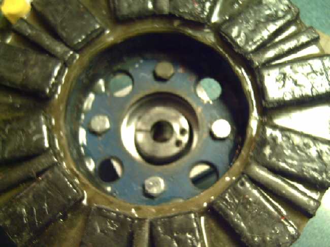 * I coupled the magnet rotor to the new
gearset with 3/8 inch bolts. (A fabulous fit with just a little work
for two things that were never made to go together - Yay!)
* I coupled the magnet rotor to the new
gearset with 3/8 inch bolts. (A fabulous fit with just a little work
for two things that were never made to go together - Yay!)
 The converter shaft assembly
refitted with the
new planetary
The converter shaft assembly
refitted with the
new planetary
* I shaped the upper pieces of wood to
miss projections under the truck - the parking brake cable and a couple
of brackets.
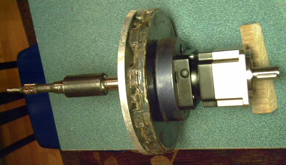
* I fitted the assembly under the truck. Seeing how it fit I changed
the way I'll do it a bit. Now I need a 32mm I.D. roller bearing for the
truck's drive shaft.
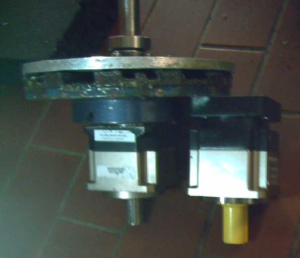
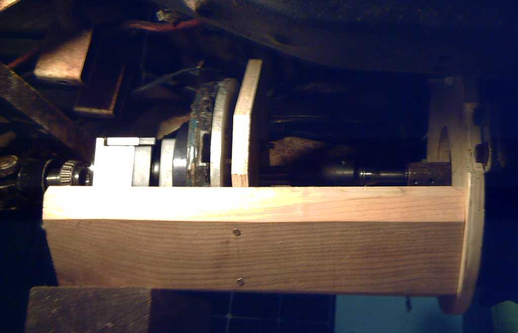 Magnetic torque converter
assembly under truck
(less 'shaped' upper 2 by 6'es),
Magnetic torque converter
assembly under truck
(less 'shaped' upper 2 by 6'es),
attached to Curtis AC35 motor at right.
Far left the front end of the drive shaft to the rear
differential fits (poorly) over the planetary gear's output shaft.
Shaft & rear end of converter to be steadied by
roller bearing (to replace cone bearing in foto).
Discussion of Nickel-Zinc Battery Chemie
I did a bit of reading on nickel-zinc (seeing how I'm
trying to
make a fairly similar chemistry). The big weakness of course is the
rated 300 cycles recharging life (if you're lucky), which I hope to
change to "indefinitely rechargeable".
Of presently available small cylindrical alkaline batteries
(considering Ni-Cd as obsolete: low energy and usually short life):
Ni-Zn: 1.6+ volts (they charge to almost 2 volts. 1.7V might be a
better nominal rating. Short cycle life compared to others.)
Mn-Zn: 1.5V (not rechargeable. Highest energy storage matching lithium
types on a single (and only) charge.)
Ni-MH: 1.2V (Longest cycle life)
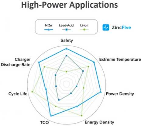 "ZincFive.com"
touts Ni-Zn for uninterruptable backup
power supplies. The reason they are especially applicable in that
particular application is that they can replace even worse lead-acid
power and
they are little cycled - only during power failures, hence may give
long service life.
"ZincFive.com"
touts Ni-Zn for uninterruptable backup
power supplies. The reason they are especially applicable in that
particular application is that they can replace even worse lead-acid
power and
they are little cycled - only during power failures, hence may give
long service life.
Someone bought some "AA"
and "AAA" size Ni-Zn cells and
reviewed them on line. He didn't get many cycles out of them (15
instead of
300) and the higher voltages fried some of his appliances. But he also
showed his charger, including opened up, and it was a cheap piece of
crap.
It's funny how for battery tools with lithium cells, such
careful
attention is paid
to proper "intelligent" chargers which work "just so", but
for alkaline batteries any piece of garbage that puts out a voltage
will do - including the many chargers that never shut off and just keep
on
charging fully charged cells full bore. Unless these are watched
closely the cells are
inevitably left in too long, get hot and lose their internal moisture
out the seams. (I guess the companies care about being sued because
their lithium product exploded and injured or killed someone or burned
a house down, but they could care less about any other batteries
failing and shortening their product's life.)
This is a typical story of zinc rechargeable batteries so
far. In spite of their high energy density by weight they are little
wanted as they are today. This is a 150 year old story I have been
wanting to change in my battery research.
A special use for Ni-Zn dry dells even as they are is in
devices that claim
"the battery is low" and won't operate, or operate properly, with
Ni-MH's. One of each type, or one Ni-Zn and two Ni-MH instead of all
Ni-MH can make them operate. So I bought a few.
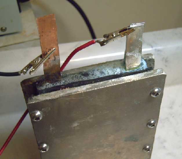
My New Chemistries: The Plus Sides
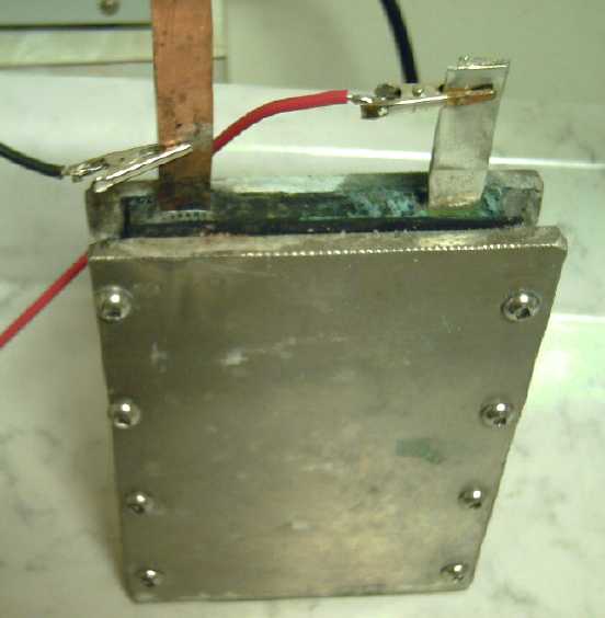
External
clamps battery.
Entire groups of cells are
to be sandwiched together.
 The
theoretical energy by weight of beta nickel oxyhydroxide in
a cell is 289 amp-hours per kilogram. But in practice in an electrode,
it actually only manages about 90 AH/Kg. Replacing the nickel oxides
electrode (the "Ni-" in "Ni-Zn" etc) with mixed
nickel-manganese oxides (AKA "nickel manganates" ... AKA "NiMn-" for an
abbreviation?) should more than double this to around 200 AH/Kg and
increase available current capacity. But I [at long last] have
discovered that the reaction voltage is so much lower than I
expected that I kept giving up, thinking something was wrong. And what
I had thought was "high self discharge" was merely the overcharged
cells drifting down toward their actual reaction voltage.
The
theoretical energy by weight of beta nickel oxyhydroxide in
a cell is 289 amp-hours per kilogram. But in practice in an electrode,
it actually only manages about 90 AH/Kg. Replacing the nickel oxides
electrode (the "Ni-" in "Ni-Zn" etc) with mixed
nickel-manganese oxides (AKA "nickel manganates" ... AKA "NiMn-" for an
abbreviation?) should more than double this to around 200 AH/Kg and
increase available current capacity. But I [at long last] have
discovered that the reaction voltage is so much lower than I
expected that I kept giving up, thinking something was wrong. And what
I had thought was "high self discharge" was merely the overcharged
cells drifting down toward their actual reaction voltage.
The low voltage has led me to some dissatisfaction with
this chemistry that I've pursued for so long, as a NiMn-Zn cell turns
out to
be seemingly only about .75 to .9 volts. But still given the higher
amp-hours, as a rough estimate the 85
WH/Kg of present Ni-MH cells would increase to maybe 125 WH/Kg for
NiMn-Zn.
If cells with "dirt cheap" materials costs are mass
produced economicly and easily interconnected, it doesn't matter how
many there are if there is less total mass of cells for a given storage
capacity.
While the NiMn-Zn combo might be okay in EV's, it might be
better suited to mass storage. Manganese and zinc are cheap and they
can contain much less nickel than Ni-Zn, so the cells should be
less than half the price of lithium types and safer, environmentally
benign, and they should be extremely long lasting and highly
recyclable if no longer wanted.
I started thinking again of using nickel oxides to make
higher voltage cells. They work, even if the amp-hours per weight is
rather low. (Manganese oxides alone evidently don't recharge properly
because the discharged state (Mn2O3 or Mn(OH)3) is an electrical
insulator.)
But as 2023 began I had a fresh look at cobalt oxides and
recognized they seemed to have some subtle but important advantages
over nickel oxides. Although superficially the redox formulas and
numbers for nickel and cobalt oxides look very similar except for
cobalt having a lower reaction voltage, cobalt oxides are more dense,
more conductive, and likely to provide in actual practice much more of
their theoretical 288
amp-hours per kilogram than nickel oxides (@~90 AH/Kg).
If it provides high amp-hours by weight like nickel manganates do, at a
higher voltage, then it should really be the very best plus electrode.
To my surprise it only costs around 1.5 times more than nickel oxide.
I don't know if others have missed this, if it
isn't as good as it looks, or if others just thought cobalt was too
costly to consider. Three different sources give three very different
pH14 alkaline reaction voltages: -.2, +.17, +.42. I'm rather expecting
the center figure is close, but it could be anywhere from about +.2 to
+.45 in
salt. I have some cobalt oxide powder from a pottery supply store to
experiment with, so I'll soon find out how it works and what cell
voltage is attained!
Assuming cobalt works well, there might be a place for
both
types: nickel manganates + zinc for economical bulk, even utility scale
storage, and cobalt oxides + zinc for high performance and light weight
per KWH - as in EVs.
But here I am seriously trespassing into January territory.
And the Minus Sides
Zinc is high energy at 820 AH/Kg. Until now, no one seems
to have been able to make a long lasting zinc electrode because the
molecules have a temporary soluble state as it discharges before they
turn into zinc oxide, and these dissolved ions are free to migrate
through the electrolyte. During recharge, these migrant ions turn back
into zinc where they touch the zinc sheet, but can build the sheet out
in fine threads instead of plating smoothly. Soon these zinc
"dendrites" penetrate the separator paper. They stick the zinc sheet
and separator solidly together, then they go on right through the paper
and short to the positive electrode, killing the cell. (Similar to but
worse than
nickel cadmium.) I seem to have a solution to this problem -- the "holy
grail" of battery making for 150 years now -- in SDBS, enabling
potentially "everlasting" higher energy aqueous battery chemistries
with zinc negatives.
Also I might get back to
the metallic manganese negative
electrodes I was experimenting with 10 years ago. [People thought
manganese
couldn't hold a charge in water, but I got it to work with trace
additives. More under
"Detailed Project Reports" - "Electricity Storage".] The
cells (Ni-Mn) charged to about 2.6 volts, so theoreticly only five
would be needed for a
nominal 12 volt battery. (Take that, lead-acid!) If further experiments
prove them practical,
Ni-Mn would provide highest available aqueous battery voltage, and
perhaps higher energy density cells
than zinc, possibly as high as 200 WH/Kg and hitting the density range
of lithium-ion cells. It depends on how much of the
theoretical capacity potential the Mn <=> Mn(OH)2 reaction
provides in actual use.
I went from writing about the theoretical
possibility to realizing I had eventually figured out or recently
solved self discharge and degradation problems I had been having
with them so long ago now and deciding to give it
another try. But I remain unsure whether they will actually perform as
well as zinc - there's nothing like a solid sheet of metal for high
current capacity.
I may well
try electrodes of both cobalt oxides (+), and metallic manganese (-).
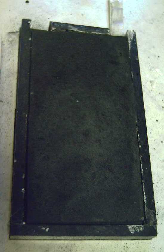
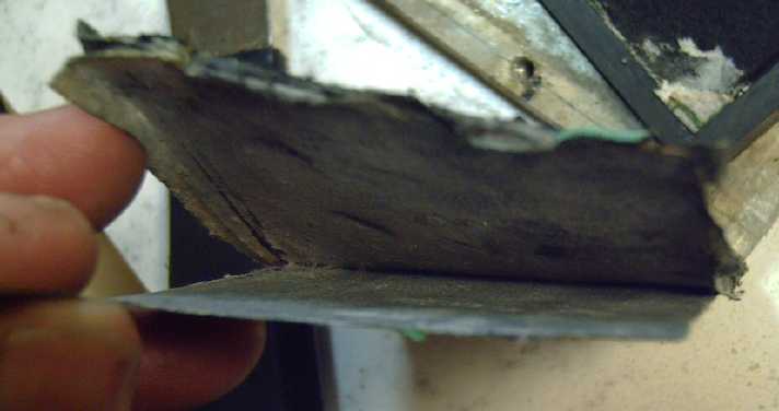
Grand new Cell Design & Experiments
Graphite felt
electrode in
ABS plastic
shell
 Among other things, I came up with what
seems like a fantastic plan for externally clamped, flat plate cell
construction, potentially with manganese negatives: use graphite felt
for both current collectors, and impregnate the appropriate
nasty nano-powders into the felts by vibration, using (eg) a palm
sander. Since there is no solid sheet between the faces, the electrodes
are bi-facial. Stack as many alternating electrodes together as desired
for a cell of any capacity, with (of course) a separator paper at each
face. And the more faces, the higher the current capacity will be.
Connection to each electrode is external at the felt terminal tabs.
Each cell could be wrapped with (eg) packaging tape and the cells put
into a common case, then all clamped together with the external
clamping plates to compact the electrodes. With nickel manganese oxide
and metallic manganese, assuming one can put substantially more grams
of powder in than there are grams of felt, excess weight of
non-reacting material would be minimal. That could yield
similar energy density to lithium cells!
Among other things, I came up with what
seems like a fantastic plan for externally clamped, flat plate cell
construction, potentially with manganese negatives: use graphite felt
for both current collectors, and impregnate the appropriate
nasty nano-powders into the felts by vibration, using (eg) a palm
sander. Since there is no solid sheet between the faces, the electrodes
are bi-facial. Stack as many alternating electrodes together as desired
for a cell of any capacity, with (of course) a separator paper at each
face. And the more faces, the higher the current capacity will be.
Connection to each electrode is external at the felt terminal tabs.
Each cell could be wrapped with (eg) packaging tape and the cells put
into a common case, then all clamped together with the external
clamping plates to compact the electrodes. With nickel manganese oxide
and metallic manganese, assuming one can put substantially more grams
of powder in than there are grams of felt, excess weight of
non-reacting material would be minimal. That could yield
similar energy density to lithium cells!
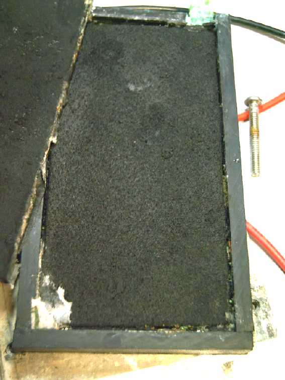
With the
separator paper
treated with SDBS, in disassembly after two weeks the
zinc
electrode and the paper still come apart cleanly. (barring a few small
patches)
This is a "game changing" result promising potentially everlasting
zinc cells.
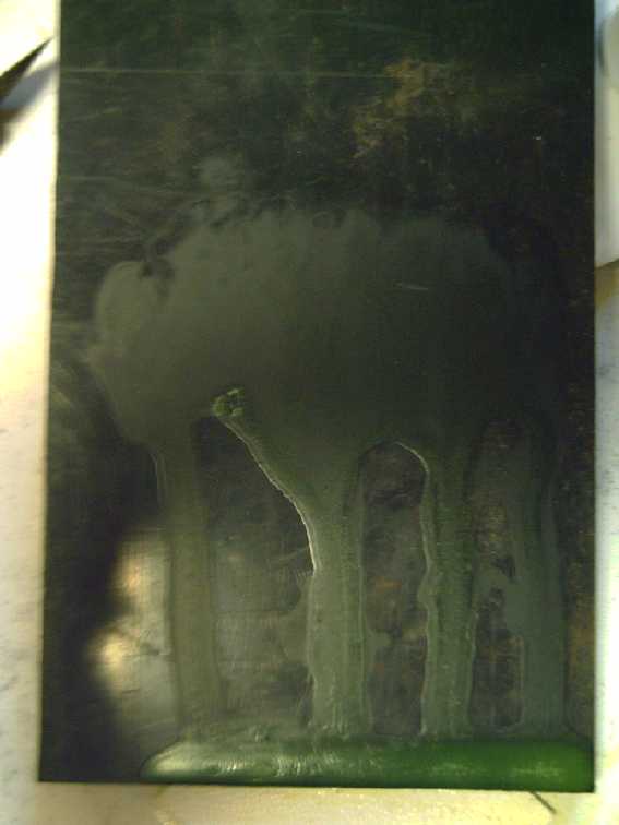
 So I spent most of the month on
batteries again. I tilted a plastic plate and let Sunlight dishsoap
trickle down it, and I made the assumption that the sodium
dodecylbenzenesulfonate was the film left behind that didn't flow down
to the bottom of the sheet with the rest. I scraped it off and painted
it into the separator sheet. It seemed to work quite well at keeping
the zinc from
growing dendrites into the paper, which normally soon sticks the paper
solidly onto the electrode. (A few small spots were stuck - the
sulfonate extracted from the dishsoap may not have been very pure.)
So I spent most of the month on
batteries again. I tilted a plastic plate and let Sunlight dishsoap
trickle down it, and I made the assumption that the sodium
dodecylbenzenesulfonate was the film left behind that didn't flow down
to the bottom of the sheet with the rest. I scraped it off and painted
it into the separator sheet. It seemed to work quite well at keeping
the zinc from
growing dendrites into the paper, which normally soon sticks the paper
solidly onto the electrode. (A few small spots were stuck - the
sulfonate extracted from the dishsoap may not have been very pure.)
With this problem solved, zinc should be better than most
any
other water-based negative electrode.
 Also seen in cell disassembly,
the graphite
felt NiMn2O4 electrode
Also seen in cell disassembly,
the graphite
felt NiMn2O4 electrode
 Generation of gas bubbles as the
nickel & manganese oxides convert
to the mixed oxide
Generation of gas bubbles as the
nickel & manganese oxides convert
to the mixed oxide
I got some performance out
of the new test cell, but not a lot. I discovered that the reaction
voltage of nickel-manganese oxides is substantially lower than I had
expected, and in fact in forming them by charging and discharging
nickel hydroxide and manganese dioxide, the voltages dropped as the
amp-hours improved to the point where I suddenly realized I had had
working cells (NiMn2O4+n and Mn [metal]) way back in 2013 or 2014, but
because of the falling voltages and reducing charge retention at the
higher voltages as I proceeded, I had thought they had
deteriorated and I gave up on them. So the dual oxide
has been perplexing and frustrating to work with. And the range of
voltages, the
slope as it discharges, is a little disheartening. So I was thinking of
going for straight "Ni-" (nickel oxyhydroxide) cells notwithstanding
that it has only around 90 effective amp-hours per kilogram instead of
the 200 of the dual metal substance.
Transgressing on January, even until now I had still
misjudged
how low the reaction voltage of the nickel manganates was. On January
3rd I did a
load test with a 30 ohm resistor for 12 hours. It started with the
usual dropping voltages -- for 4 hours, until it was down below 0.8
volts. Usually I have cut off tests at well above one volt and am
distressed with the performance. Where are all the amp-hours my cells
should have? Why don't the voltages stop dropping at some flat level?
But the nickel manganates have a lower reaction voltage
than I ever suspected, seemingly around -.4 or -.5V instead of a plus
value,
actually subtracting from the -1.25V or so of the zinc. It ran for the
next 8 hours at just above .75 volts, even gaining 5 millivolts to
.756V in the
later hours. So it actually did have a particular flat voltage
it would run for a long time at! And it dawned on me that it actually
had all those amp-hours that I had thought it should - just at this
lower
voltage. And that drawing only 25 milliamps from a battery with several
amp-hours in it, and with it the flat voltage that I finally discovered
it had, the cell would probably run for 4 or 5 days or more before it
petered out. It was probably still 90% charged after 12 hours when I
stopped it! Furthermore, now that I had actually drawn that 10% of its
charge from it, it didn't need weirdly high voltages in order to absorb
at least a little charging current.
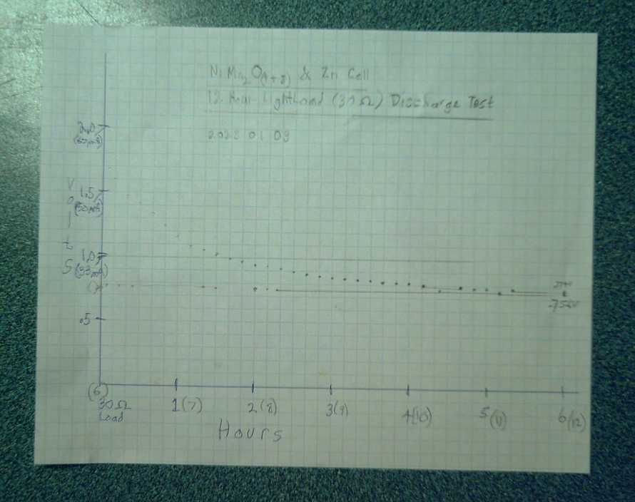 Graph of the cell's discharge
voltage with time.
Graph of the cell's discharge
voltage with time.
I only allowed for 6 hours on the paper so I had to double back to the
left for the second 6 hours,
within which time the voltage hardly changed.
Obviously it could have continued discharging at .75V, 25mA for several
days if I had left it going.
My one remaining major concern is that my cells seem to have puzzlingly
low current capacity. They're great for charging and driving a small
load slowly over days, hopeless for driving a car for an hour. In this
cell, instead of 100 or 200 mA/sq.cm of interface between electrodes
with a heavy load, it's more like 10 to 20. With the good current
capacity it should have, voltages in the above graph would
surely be a little higher. Well, I'm sure there's some cause and a fix
to be found. Hopefully it won't take another decade!
In
Passing
(Miscellaneous topics, editorial comments & opinionated rants)
Smol
Thots
* Amazon Fraud: How?
 I got another
message on my cell phone (that only a very
few friends have been given the number for and on which I had blocked
the number
Amazon had previously messaged me from): "Your Amazon account has
ended." And there was no charge on my credit card. Thank God!
I got another
message on my cell phone (that only a very
few friends have been given the number for and on which I had blocked
the number
Amazon had previously messaged me from): "Your Amazon account has
ended." And there was no charge on my credit card. Thank God!
It seems the way they sign you up is when you place an
order it says "Free shipping with Amazon Prime". Who doesn't want free
shipping? Unless you un-check the box, hey, you've signed up
for an "Amazon prime" account and for being billed 14.99 $US monthly
from
now on! (*Somewhere* I must have entered a password, but it wasn't
evident to
me, and obviously not to others either, that we were signing up for
something
with ongoing billing. We were just trying to order one item.)
Shown is fines Amazon incurred in Europe in 2021 for
breaching European laws.
* It is disturbing that so many major corporations have become gangs of
pickpockets seeking any stealthy means to extract money from people,
legal or moral or not -
especially as ongoing charges. And that they only pay fines as
"corporations": even the head pickpockets in upper "management" never
get punished, fined or even fired, or removed by government.
* And today often the CEOs and upper management pickpocket from the
company itself and from shareholders by various manipulations,
sometimes enriching themselves personally so much that the company they
manage goes bankrupt. (Eg, Kodak, Enron...) As someone said, "The best
way to rob a bank is to own it."
* Those having attained positions of power by unscrupulous means are
among those who hate truth. I understand that 67 journalists are known
to have been killed globally in 2022 (as of early December), said to be
up from 47 in 2021. There are probably more and some "disappeared",
that simply haven't been recorded as "killed journalists". Washington
still wants revenge on Julian Assange for exposing its war crimes in
Iraq almost 2 decades ago. Right now Ukraine, and the Donbas, are the
most dangerous places for a journalist to be. But as (for example)
Michael Hastings showed us in 2012, anywhere can be deadly if you have
a story about the wrongs of the wrong people or organization. Any idea
why we only hear the "fake news" that "TPTB" want us to hear on the
mass media?
* But it's not just corporations: The unfortunate tendency to look on
others outside one's own circle as "resources to be plundered" rather
than as fellow human beings has become all too pervasive with
individuals within our societies, too.
* I have been hearing that stores in some American cities are becoming
targets of organized shoplifting, where a whole group/gang connects on
social media, sets a date, and everyone comes in at once and robs the
store, saturating any store security. More and more stores are closing,
and this has been the reason in some cases. In many cases, especially
furniture stores for example, it's just that so many people have no
money for things they don't urgently need.
* With the growing level of
shortages and crop failures, fuel and energy inflation and egregious
costs for housing, even basic necessities are becoming unaffordable for
too
many people, even the greater majority. I was a bit dismayed this month
to hear someone say there
was rampant crime
in Edmonton Alberta where I grew up. That would be just about the last
major
North American city I would have expected it in. How much longer can
20th century civilization endure such growing levels of trouble and
self-serving disunity coming from every corner?
* One of a kind Lamp I have a lamp with a twist switch
that only takes one click to turn on or off instead of two. Came with
the house. Never seen one before. What an ingenious invention!
* Good military analysts expected that Russia's now strong mobilized
forces
would make their big attack on Ukraine once the ground was solidly
frozen so that tanks could roll across the open fields without sinking
into the mud. Somehow I suspected something would go wrong. It would be
too simple to just have some decisive action put a quick end to the
fighting. On the 17th I checked on a world weather map. Sure enough,
while we were having a cold snap here (-5°C the next morning),
temperatures in Ukraine were mild, above or near freezing except in the
northernmost parts. As temperatures here plummeted to -7° and even
-11° [a
record?] for days on end - unheard of around here and much colder
inland -
Ukraine hovered around zero to the end of December and even warmed up
into January -- hardly the usual winter deep freeze the Russians were
said to be waiting for! In fact all Europe has been wondering "What
happened
to winter?" And the American or NATO or Ukrainian side (whatever one
calls it) has been gathering forces to oppose such a move that would
have been
simple and decisive in November or December.
As Scottish poet Robbie Burns said, "The best
laid schemes o' mice an' men gang aft a-gley." From another viewpoint,
one may glimpse the workings of our governing spirit overseers: "The
Most Highs rule in the affairs of the Kingdoms of Men." and "All things
work together for the progress of men and angels."
* Instead, local Donbass militia groups with Russian
artillery support continued localized
attacks notably around the fortified transportation/communications hub
of Bakhmut
in
Donetsk while Ukrainian (and foreign mercenary?) forces continued their
8 year long artillery
terror shelling of Donetsk city from their well-dug-in nearby
fortifications. Russian speaking refugees flee East and Ukrainian
speaking refugees flee West to escape the war. As best I understand it,
10 million out of 44 million have fled so far.
* Some in authority seem to want to ban ranching and production of
meat. They seem to reason that to have a cow eat vegetation is less
efficient than having people eat vegetation directly. But it's a false
argument because many lands that are good for ranching aren't good for
crop production. And cattle poop is good for the soil. The rich
prairies of the Americas were made by kazillions of grazing bison
before the
first settlers ever looked and saw ready cleared land free for the
taking.
ESD
(Eccentric Silliness Department)
* What is the relation between a tax and attacks?
* A disgruntled worker can cause many problems. An office should hire
only gruntled workers.
* I keep seeing companies filing for Chapter 11. Dang, I always miss
the first 10 chapters!
* What gets cooked in a chicken ckichen?
"in depth reports" for
each project are below. I hope they may be useful to anyone who wants
to get into a similar project, to glean ideas for how something
might be done, as well as things that might have been tried, or just
thought
of and not tried... and even of how not to do something - why
it didn't
work or proved impractical. Sometimes they set out inventive thoughts
almost as they occur - and are the actual organization and elaboration
in writing of those thoughts. They are thus partly a diary and are not
extensively proof-read for literary perfection, consistency,
completeness and elimination of duplications before
publication. I hope they may add to the body of wisdom for other
researchers and developers to help them find more productive paths and
avoid potential pitfalls and dead ends.
Electric
Transport
Magnetic Variable Torque Converter with Planetary Gear
Magnetic Torque Converter =
Performance!
Power equals torque times speed. With a fixed 5 to 1
planetary and 2.2 to 1 at the differential, the truck would have had 11
to 1 reduction between motor and wheels. That would be sufficient
torque to get it to start moving, even up a hill. But with the 10 to 1
planetary making it a theoretical 22 to 1, at low speeds and higer
torques the motor speed is faster with the
same torque. The truck should really accelerate fast even with
its small motor. Yet as it hits 30 or 40 or 50 KmPH and the foot is
raised on the accelerator reducing the torque, it will still head
toward 2.2 to 1 (torque converter toward 1 to 1) and the motor won't be
turning very fast. Even at 100
KmPH it won't be going much more than 2200 RPM, which is under half its
continuous speed rating.
In other words, with a well configured magnetic torque
converter even very small motors (like the 3500W one in the Sprint)
will give great lower speed performance and be able to climb steep
grades and almost jump away from stop lights.
Next this has to be assembled and demonstrated on the road...
The New Planetary Gear
[20th] The new 10 to 1 planetary gear arrived. I had finally given up
and thought it would be after Christmas. The front half of the new gear
looked like it had come from the same mold as the old gear. Could I
swap the back halves and then not have to change the shaft? It seemed a
bit dubious, but I had wanted to see what sort of lubrication was
inside them anyway.
[21st] I opened them up. The 10 to 1 sun gear on the new unit was a
tiny red dwarf. I'm actually a little nervous about how small it is. If
it had to take too much torque, it might actually break off its shaft.
I console myself that it sees only 1/10 the torque of the output, and
that with the body 'free' to turn, it should never get a hard jarring
from a sudden force. But I'm actually wondering whether a 9 or 8 to 1
gearset might just be more robust. Either that or use a larger physical
size planetary. Anyway, this one is going in the truck now. If it's not
strong enough, I'm sure I'll find out only too soon.
Old & New gearset.
The box said deltaww.com .
Apparently that's the maker, with many international offices.
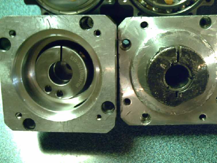 On the new one (L), the input is
recessed, by
making the body longer
On the new one (L), the input is
recessed, by
making the body longer
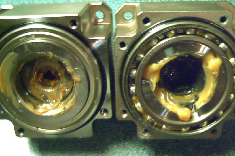 The Planets assemblies inside,
& the grease
The Planets assemblies inside,
& the grease
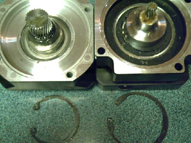 The sun gears (new 10:1 reduction
sun seems
awfully tiny!)
The sun gears (new 10:1 reduction
sun seems
awfully tiny!)
 The new one's output shaft is a
bit longer
The new one's output shaft is a
bit longer
The lubrication was a thin grease. I figure
that it's thin enough that with the body turning it will get thrown
around inside and continually lubricate, rather than get flung away
from the gears and gradually lose lubrication as with a stationary
housing - Yay! (That's what did in the gear teeth in my first Ryobi
skill saw running the handheld bandmill when I was milling, when after
much
milling the grease was no longer where the gears were. I didn't want
that happening on the truck. (Hmm... Maybe I should open up the gears
on the present saw
on the bandmill and see how it's doing?))
Inside, the sizes were all different. There was no piece
of one that looked like it would fit in the other housing. All the snap
rings were different sizes. So much for that idea! I put them back
together as they were.
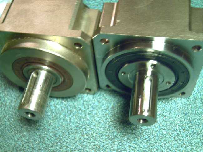
But on the old one the input clamp was external, and on
the new one it was recessed inside, making them almost the same length
from shaft end to shaft end. If the end of the motor shaft needed to be
trimmed at all it would be by just a few millimeters, such a small
amount that no more of its length would need to be reduced to 19mm.
Yay! Also the output shaft was an extra 4mm longer than the old one.
Any bit longer to insert into the tenon on the rear drive shaft is a
plus,
because there isn't much to grab onto and it carries a lot of torque.
It's surely the weakest link.
The outer housing however was an extra 27mm or so longer,
putting the magnet rotor that much farther up the shaft. So the center
bearing and alume rotor would have to move along to compensate, and for
that the motor shaft
would have to be turned to 1.0 inches for that further length. All very
doable on the lathe if it wasn't freezing cold outside and in the
workshop. The garage was also pretty chilly for lying under the truck
and struggling to fit things together. If the whole project doesn't
wait for spring, it will probably sit at least until this cold snap
ends. 2023 approaches.
[29th] It warmed up. Sometime in there I had figured out that I could
mount the alume rotor on the reverse side of the huge washer/disk it
bolted to, and changed it. This moved it up the shaft about 3/4 of an
inch. Trouble is the new planetary is over an inch longer than the old
one, so I expect it'll still be 1/2 inch or so too long between motor
and rear wheels drive shaft. But I'll try fitting it all on. If it fits
it saves me some lathe work.
There were
four new holes in this gearset body for an
allen wrench to fit through, owing to the extra length obscuring some
screw heads. They were just the right size to tap for 3/8 inch bolt
threads. The holes in the magnet rotor were just a little off and a bit
small, so I had to spend some time filing them so they fit and centered
the rotor. (Still, really nice that everything was so miraculously
close to a perfect fit!) I'm much happier with some big fat bolts to
take
the torque between magnet rotor and gearset body than the puny #10-24
holes they came with
or even the 1/4 inch bolts I drilled out the old unit for.
Shaft assembly with new planetary
[30th] I tried fitting the whole thing
under the truck. Sure enough, it
was too long... unless I didn't put the bearing on the rear shaft. But
that did make for more overlap length to connect the drive shaft to.
Could I put a bearing instead on the outside of the socket of the drive
shaft? That would be better. It was smooth. 32mm. I could probably
order a bearing for that. I could make anything to fit the length and
outer diameter of a bearing as long as it was 32mm I.D.
I found a cup & cone bearing that had a shim on the
inside from some long ago project. It was just about right. Nah! I
would be better off to find a one piece ball bearing or needle bearing
race.
I trimmed the top boards to fit around obstacles under the
truck frame, notably the parking brake cable, but haven't reattached
them.
The main frame of the variable
torque converter
fitted under the truck
Unipolar
Axial
Flux
BLDC
Motor
I was wondering where I
would get steel plate to make molds for the PP body parts -- or should
I try alume molds again? Sheldon
had mentioned that a 4 by 8 foot sheet of 1/4 inch steel had gone up
from something like 150$ to 600$ -- plus shipping and I hate to imagine
the cost of shipping to here. Suddenly I remembered: I still have 1-1/2
of the two 80 gallon propane tanks made of 5mm and 6mm steel that I got
especially to make plastic molds from! Duh! Bending the curved pieces
straight has been a challenge, but the pieces for the motor molds will
be somewhat smaller than the big plate mold I was making - hopefully a
little easier. (And maybe I should
try cutting them with the plasma cutter this time?, instead of using up
so many angle grinder zip disks!) There was one loose piece 16" by 21",
and I "sort of" flattened that. I improved my technique with a couple
of small bars of steel to form bend points more where they were needed,
and at least I got it flatter than the previous piece. I wonder if
anyone else has a better method or some heavy steel roller (unroller?)
I could use?
[8th] I spent the evening with the CNC router. After some of the usual
frustrations with unfamiliar software that worked differently than what
I'd used before, I had it work correctly for a dry run with the router
turned off. It went through all the motions of moving the carriage
around through all the steps for cutting out the magnet placement jig.
I learned a bit about setting default parameters and feed rates, which
had all been pre-set in the old drill-router I had had in Victoria
until 2017. I must say a stepper motor on the vertical "Z" axis seems
much better than than the compressed air plunger that lowered that
one's router. (Why, one could even make cuts to different depths -
right through the material or only various indents. A 3D un-printer.
What a concept!)
One thing I realized to my annoyance in setting "max.
travel X" and "Y" was that although the table was 29" by 29", the
workpiece cuts could only be 19" by 22" max. One inch legs in the
corners underneath kept the 8 inch wide left and right gantry pillars'
mobility to 10" less than the depth, and the router carriage was about
7 inches wide. and hit end stops on the gantry pillars. Perhaps if I
ever need more depth I could extend the tracks beyond the back of the
table. How feasible that would be I'm in doubt. Taking the legs off and
devising an alternate mounting could bring it up to 21" deep.
Anyway, 19" is plenty for the present motor project, and
maybe for anything I'm likely to do with it.
Once the machine had run the course flawlessly I called it
a night and was happy to have got that far.
[9th] I mounted a piece of 1/4" plywood on a center of 3/4" plywood. I
ran the course again and discovered that the whole pattern was running
about 2/3 of actual size. I ended up running the configuration software
again and telling the software that the motors were 324 steps per
revolution instead of 200, which must be some standard. The "Z" motor
said "200" on top. But apparently the pitch of the screws moved things
by an an inch over more than one revolution of each motor. or something
equivalent.
Finally I went to put a router bit in the collet chuck...
and discovered that it, the only collet I had received with it, was 6mm
instead of 1/4" or any other shank diameter one might readily find in
North America. My other collet chucks from other machines were all too
big for this one. I put in a 1/4" bit but it wouldn't go in all the
way. It drilled the five holes in the center, but predictably it fell
out after butchering an inch of the plywood when asked to cut sideways.
I got on line to AliExpress. Sure enough, 6mm is a
standard size router bit shank in the rest of the world, and I ordered
some bits. "February 10th" is the estimated delivery date. Knowing how
deliveries are going today, I'll be lucky to see them by spring. If
ever. So close to being able to route, yet so far! The other option
would be to make a carriage for my regular handheld router. That would
be a considerable project in itself.
Well, I could work on designing the chassis of the motor.
(Instead I went back to battery chemistry & design.)
(The bits arrived January 7th.)
Other "Green" & Electric Equipment Projects
Winter Gardening
Window & LED Gardening
The romaine lettuce and spinach planted in two rectangular
pots under two 40W red-blue LED grow lights in November started growing
well once they were very close to the lights and so were getting enough
in 9-11 hours a day of the lights. One light quit. (They're quite old
now.) I've ordered a new 100 watt 30 x 45 cm light The lettuce
has been yielding leaves for burgers and salads. I had to seed more
spinach as only a couple came up, and I've only had a couple of small
leaves. But finally the first two are growing bigger.
The lettuce must be worthwhile, because I saw a head of
romaine in the grocery at 9.99$ !
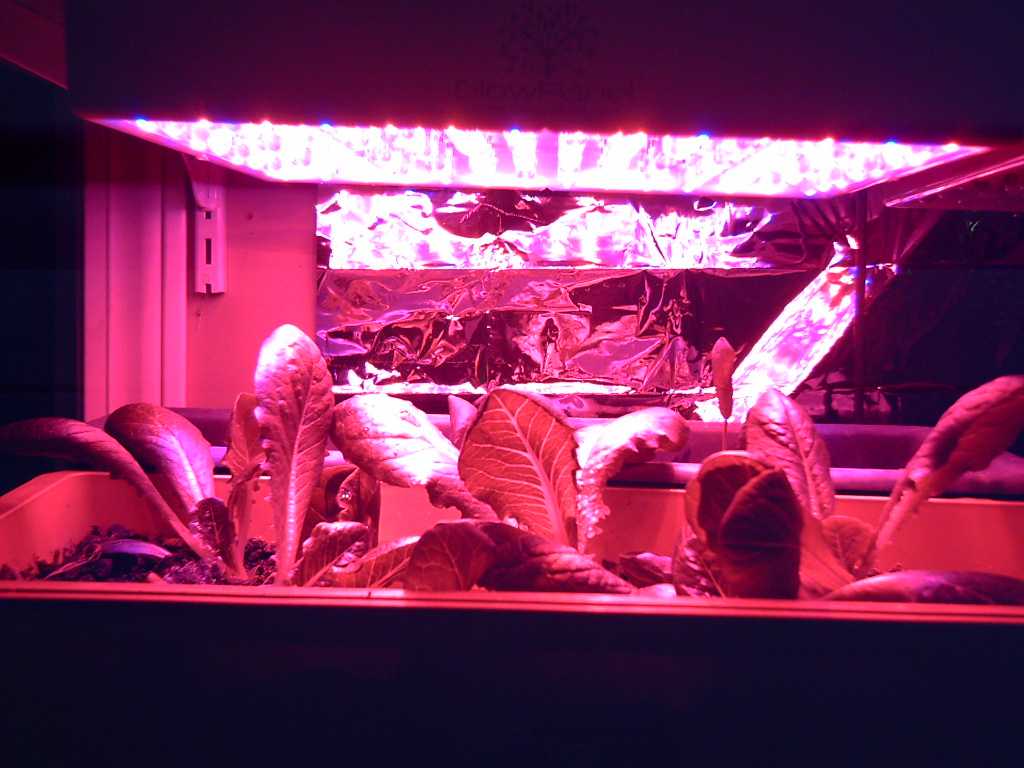 Lettuce and spinach under LED
light.
Lettuce and spinach under LED
light.
They had to be this close to the lights to survive.
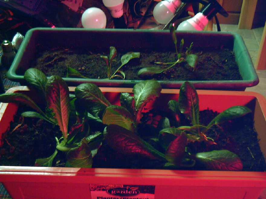 Seen in normal light.
In the bay
window with added lights, a pepper died from
having water always in a tall drip tray around it (overwatered) and the
other three peppers have aphids, but I'm still using the peppers that
started in the summer and ripened over the fall - a few are left if
only because I don't eat them very often. After 3 months with no
flowers, one banana pepper has a couple. The larger "restarted" cherry
tomato has a couple that should be ripe soon, more to follow, and
continues to flower. The other one isn't doing much.
I grew more onions last summer than I'm ever going to use
up, even keeping them in a cold place. After all these years with so
little success growing onions, I planted a lot. How was I to know
they'd all make nice big bulbs? And plenty of garlic.
Electricity
Storage
Manganese Negative Electrodes (~ -1.5V)
This is the "too
technical"
part of the discussion of batteries in "Month in Brief", about my
experiments 10 years ago wherin I created chemicly successful metallic
manganese electrodes that might still make higher voltage, higher
energy density water based cells.
People said it couldn't be done, that the reaction voltage
of manganese (~-1.5V) was a little too high and that in water it would
spontaneously convert to Mn(OH)2 and bubble H2 gas from the water
without the electrons bothering to flow through an external electrical
circuit. I reasoned that if trace substances could be added to zinc
electrodes to raise the hydrogen overvoltage so they could charge
better without bubbling hydrogen, then for the extra .3 volts or so of
manganese (Zn -1.24V vs. Mn -1.57 in alkali), one might find additives
that would take it from "doesn't quite work" to "does work". First 1%
antimony sulfide got it to work, yay! ...but only if the room was below
18°C. Next summer that didn't work any more, to my considerable
puzzlement for a while. Then I put the cell in the fridge and it worked
again - Aha! Adding 3% zinrconium silicate as well got it to work into
the upper 30's° (I tested up to 39° IIRC). I only got it to
work in KCl salt electrolyte, pH up to 13, not in pH 14 KOH.
So my Mn negative electrodes held a charge! ...mostly. The
first one I tested (Sb2S3 only, in winter) had a graphite rod current
collector, and it seemed to hold its charge. I was mostly using zinc
sheets as current collectors, as well as zinc powder conductivity
enhancement. But (which I didn't figure out until much later) with the
high voltage, the zinc plate bubbled hydrogen and formed zinc hydride
continuously where it wasn't near the Mn electrode mix with the
overvoltage ingredients. So the self discharge never completely stopped
and it wasn't so long before the terminal tabs on the zinc plates would
corrode completely away around the water line and the cell would be
disconnected. I had thought zinc should work because with the higher
reaction voltage of manganese the zinc would remain in metallic form. I
don't know why didn't think it would bubble hydrogen, also I was
unaware that zinc could form a hydride and degrade, so didn't
understand the degradation, the hydride being similar light color
powder as zinc oxide.
Some other metal (lead, bismuth?) or graphite might work
for the negative current collector, or else perhaps a protective
(non-conductive) coating could be applied to the exposed zinc. Or the
overvoltage ingredients would need to be everywhere - perhaps in the
protective coating? Come to think of it, my last experiments, using
graphite sheets instead of zinc, did seem to be working better. But I
think that one may have been when I tried MnO2 in the positive, and I
didn't understand why that wasn't recharging. Then I probably went onto
something else and didn't seriously get back to batteries for a long
time. So: a graphite sheet current collector and maybe graphite powder
instead of zinc for conductivity additive. Graphite is much lighter
than using a metal anyway, further upping the amp-hour per kilogram of
the electrode and cell. If needed a paint/coating impregnated with
the overvoltage raising substances could coat all exposed surfaces
including the terminal tab up to the connection level. Why did I stop?
Oh yes -- because I didn't understand why it kept self-discharging. In
fact, these earlier cells would have had the same problem I've just
(apparently) solved of nano powders penetrating through the separator
sheet, degrading their performance over a couple of weeks, which always
seemed to happen. Having at long length figured out some answers,
perhaps it's time to try again?
Between the nickel-manganese oxide which I was
experimenting with even back then and the manganese negative, the cells
charged to 2.6 or even 2.7 volts. They might be considered "2.4V
nominal", of which just five cells would would be required to make 12
volts. (They even lit a 2.9V LED; not brightly, but no other single
cell water based battery will!) This should be similar to lithium ion
cell energy density, by weight and maybe by volume.
And yet, if zinc can be contained and not grow dendrites
across the separator sheet, the solid metal has very high current
capacity and will yield most of its theoretical amp-hours. I suspect
manganese probably won't perform as well. So I remain torn about which
to make.
Hidden Culprit Found!
[15th] The more thought I gave to my early results, the more I thought
I would try this chemistry again. I went looking for my antimony
sulfide, which I hadn't wanted at any time since I moved here from
Victoria, and ran across a nearly empty plastic jar of KCl - USP
grade! This solved a mystery. Since I've discovered that my KCl
electrolyte salt has been a cause of self discharge all along, why was
I getting better results early on in my experiments, and then I could
never again duplicate such good results? That was it: the first
KCl I had bought at the health food store was that jar and it was pure.
After that they had switched and had [contaminated] KCl in bags. I had
switched to using the next bag I had bought, and didn't notice that it
was after that that all my cells of any kind seemed to have
serious - and mysterious - self discharge. Of course I should have
figured it out long ago, but I didn't. Instead, frustration, time after
time after time! Amazing how some little thing can throw one off track
for years - or even maybe never be suspected and change the whole
course of life. How far along would I have got years ago without this
setback?
In a lengthy search - of everything twice - I never did
find the antimony sulfide. Hopefully antimony oxide will do the job,
because I found a small bag of that and will try it. I'll certainly
know if the electrode won't charge.
New
Chemistry Batteries
[6th] Nothing seemed to
completely stop
the self discharge, but I did note that higher charging voltages (2.3
vs 2.25 vs 2.2 vs 2.1) gave better results. It still only powered a 20Ω
load for 16-19 minutes. Was it really charging fully or properly? I set
it to 2.4V. That seemed to give somewhat better results. A load test in
the evening went a little over 19 minutes.
Owing to the fact that it can take 10 minutes to recover
its voltage after a load test, it seems to me that the conductivity of
the plus electrode must be quite low.
[7th] Hours and hours on charge, and it gets incrementally better over
time. Will more charge and more charge and more charge over many days
or weeks eventually make it perform well? Should I be chemicly
pre-charging with bleach?
Positive Electrode Mix
Speaking of which, I would think that using MnO2 (or
Mn2O3) from old dry cells and mixing in the Ni(OH)2, and then putting
it in bleach, should give about the same effect as using Ni(OH)2 and
KMnO4 and water. The dry cell has graphite already in it and it all
must be pure enough already to hold a charge. The trace Sm2O3 or
Sm(OH)3 to raise oxygen overvoltage can be added any time. It won't
react.
I don't think the monel powder (which I spent so much
money, time and effort on) is needed at all. That was a left-over in
thinking from trying to do it in a similar manner to how NiOOH alkaline
cells are done with cobalt hydroxide in the mix to improve
conductivity. The graphite or conductive carbon black (herein "CCB")
takes its place. A little more Ni(OH)2 is added to replace what the
monel would have formed? The mix using KMnO4 is thus simply:
Ni(OH)2 - 25 g
KMnO4 - 40 g
Graphite Powder - 5 g
Sm2O3 - 5 g
The mix using old dry cells is a bit less certain. How
much is graphite or CCB? And was it charged (MnO2), Discharged (Mn2O3
or Mn(OH)3), or somewhere in between? Each substance has a different
amount of oxygen in proportion to the Mn. Hmm, perhaps pre-bleaching
can ensure that it's all charged to MnO2?
The mix to be bleached and purified then becomes (wt% for 100g product):
Ni(OH)2 - 29 g
Dry cell Powder (MnO2 + CCB) - 63g
Sm2O3 - 3 g
Additional Graphite or CCB power - 5 g
(proportions of Ni to Mn are approximate)
This is pretty cool as the largest ingredient is the
powder from old dry cells, which can be had for free anywhere where
they are turned in for recycling. I suppose one could get nickel and
nickel compounds out of rechargeable dry cells too, but in my
experience the "D" cells have a heavy metal case and are a bit tough to
open and extract the spiral electrode from. (If I didn't have a whole
tub of Ni(OH)2, however...) But, also: since the negative electrode of
NiMH is mostly nickel (with some lanthanum and cobalt: Ni:La:Co 10:2:1
ration IIRC), it too could be oxidized to Ni(OH)2 and used for the
positive. The La(OH)3 would substitute for Sm(OH)3 - I think it should
work well enough, especially as there is quite a lot of it. I expect
the Co(OH)2 would have little effect - perhaps raise conductivity a
bit, otherwise pretty benign.
Thus, both electrodes from NiMH cells could be used to
make the nickel compounds for the new cells. The metallic nickel would
have to be turned into hydroxide first in order to react it with the
MnO2. (HCl + H2O2, or mildly alkaline salt electrolyte and a "+"
charge?)
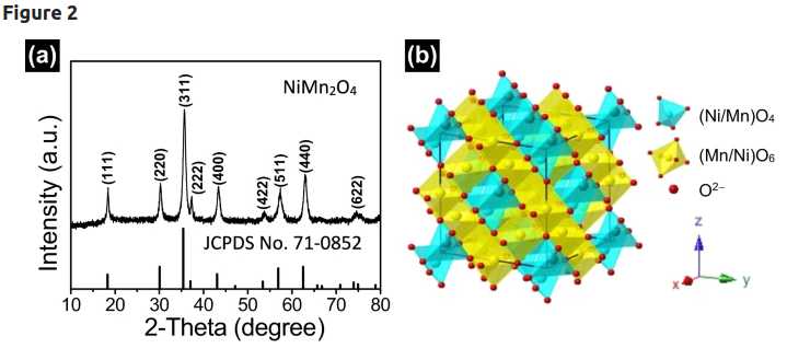 Spinel crystalline structure of
nickel manganates.
Spinel crystalline structure of
nickel manganates.
It is easy to see how oxygen ions can attach or detach, or
attach/detach a
hydrogen ion, to provide many potential oxidation states for redox
reactions.
[8th] On disconnecting, the
voltage dropped to 2.100 volts in 85
seconds instead of 50-60. But a 20Ω load test down to 1.200 volts had
somewhat lower voltages throughout and only ran 18 minutes where
yesterday morning it went for 22. What drives these changes? Maybe a
lack of salt? I had added water with weak salt to 'top it up', which
might decrease the concentration. Or the tiny filler hole I left open
to the air after that? (Oops)
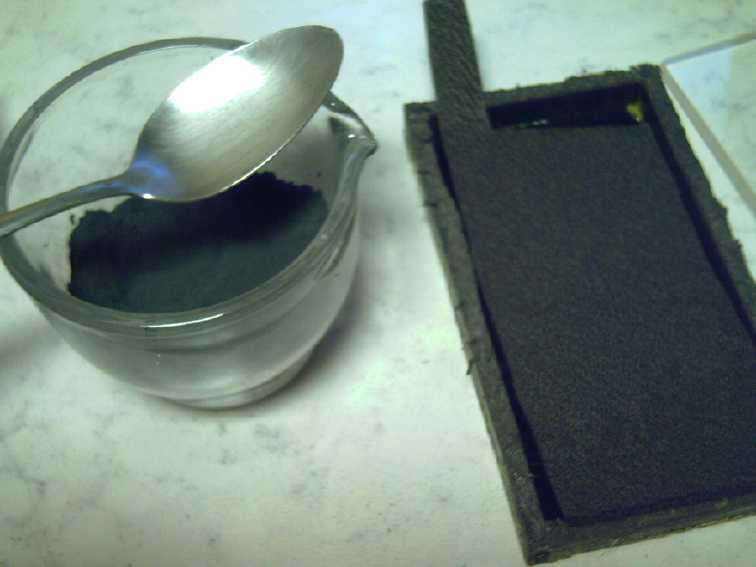
I pulled the modeling clay off a terminal and spooned some
salt onto it. It didn't seem to entirely absorb, but I put on another
piece of modeling clay to (hopefully) restore the seal.
[9th] I'm convinced I still need to somehow hold the "+" electrodes
more heavily compacted. Same pressure in the cell as when I compact
them in the hydraulic press. I think that even with the extra pressure
I've added to the clamped cell, 95% of the electrode material isn't
being utilized. As well as far more current drive and fast recovery
after running a load [presently takes many minutes!], I think the
amp-hours would go way up and the self discharge would become trivial
in proportion to the charge held.
But even the 1/4 inch plastic sides are likely to bulge
out and 1/4 inch alume end plates to bend under the pressures I think
are really needed. I could use steel end plates, or 3/8+ inch alume.
What about those sides? Wrap the cell innards in lots of winds of
packaging tape to keep the sides from bulging? Hmm, that just might be
the best answer! Maybe I need to re-think cell construction.
Or has it got lots of pressure and the problem is
something else entirely? the cell went downhill after a couple of
weeks. Probably in this case it's zinc dendrites, since it doesn't have
anything to inhibit them or restrict their growth from the separator
sheet.
Positive Electrode Chemistry
[11th] I mixed a double batch (200g) in the above proportions. I gave
some thought to what the actual redox chemical reactions might be. I'm
going way out on a limb here, as I'm not a chemist and I haven't found
much info on "nickel manganese oxides" on line. In fact, I created the
page on Wikipedia and the first paragraph is what I wrote. Someone has
added a second paragraph about magnetic properties, but it doesn't
answer many of my questions. It may be that someone who knows the art
would have to use x-ray diffraction or similar technologies to actually
isolate the molecules. I'm only going to say that the small amount of
previous research I've found makes it look promising, and it's probably
more promising in salt electrolyte than in pH14 alkali.
Compounds seen in passing in the literature on line (mostly abstracts
of research papers hidden behind a paywall):
NiMnO3
NiMn2O4
NiMn2O(4+δ)
Ni6MnO8
Ni2MnO4
(derived from "NixMn(3-x)Oy")
Here I'm going to assume that the best ratio of Mn to Ni
atoms is 2 to 1, as in NiMn2... In water, I expect some of
the "oxide"
is replaced by "hydroxide" making it "oxyhydroxide". Nickel can have a
valence of +2 or +3, and manganese can be +2, +3 or +4. If we assumed
it was in a "maximally charged" (oxidized: Ni@+3, 2 Mn@+4) state, it
might be Ni2Mn4O11. Possible oxidation
states abound (Valence in Roman numerals):
XI - NiMn2O5OH
X - NiMn2O5 or (eg) NiMn2O4(OH)2
IX - NiMn2O4OH
VIII- NiMn2O3(OH)2 (or NiMn2O4)
VII - NiMn2O2(OH)3
VI - NiMn2O(OH)4
(Later I found a lengthy molecular formula with many variables showing
that the molecules and spinel crystal structure of mixed nickel
manganates/nickel-manganese oxides can be quite complex.)
I suggest that (a) the substance overall will probably
change valence states by 3 or 4 during charging and
discharging, and (b) that the changes will mostly be between O-- and
OH- ions, so the
spinel structured substances will be largely stoichiometric, that is,
they won't swell or contract much during charge and discharge.
Again these are only somewhat educated guesses. I don't
have either the costly specialty equipment (XRD, SEM, Raman
spectography, ICP emission spectrography...) nor the
training to use them to make definite assertions. The only
things I can say for certain so far are that the electrode successfully
charges and discharges repeatedly (unlike MnO2 by itself).
I had thought that the cell would be around 2 volts open
circuit, but that was a guess at a wild card and it turned out to be
quite wrong. The cell starts out near 2 volts, but after the nickel
hydroxide has been converted into nickel manganates it's under 1 volt.
But one very good plus is that with all the available
oxidation sates it probably has 200 amp-hours per kilogram of charge
capacity where nickel oxyhydroxide (in actual use) only has around 90.
In terms of overall energy storage, the lower voltage is more than
compensated for by the higher amp-hours.
Varsol (or Toluene?) Treatment of Separator Paper
I wetted one piece of the watercolor paper with varsol and
left another plain. When the one was dry I examined them under a
microscope, half on each side of the view, to see if I could see any
difference. The only clear thing was that I couldn't focus on both of
them at once. So I measured the thickness with a micrometer and found
that the
solvented piece was .45mm and the plain one .50mm. The solvent had
shrunk the thickness by 10%, probably uniformly through the fibers
within the sheet. So they were at least a bit more horizontally
oriented, which might explain why they seemed to stop the nano powders
from penetrating through.
If there was any lateral or longitudinal shrinkage it was
so little as to be unnoticeable. Later I measured another piece with a
micrometer and then varsoled it.
141.12mm / 141.50mm = 99.73% or .27% longitudinal shrinkage, and
78.63mm / 78.87mm = 99.70% or .3% lateral shrinkage.
Yup, not very significant.
Sodium Dodecylbenzenesulfonate (herein "SDBS")
On the 7th I opened an account with SigmaAldrich.com and
put in an order for SDBS that hardly anyone had for sale that I thought
I wanted. On the 14th they sent me an e-mail asking where was the
address that this would be used at? I had said to ship it (by personal
agreement) to Westpoint Auto Parts in town, since I was sure they
wouldn't ship to a rural or residential address. After a week I had
hoped the substance was already well on its way here, but they hadn't
shipped it yet! (At the end of the month I had still had no further
contact with them!)
In the meantime I had mentioned it to someone and he
mentioned "making a chromatograph" as a potential means to separate it
from the dishsoap. Apparently if one dissolves something like that in
water and puts a piece of paper sticking out of it, the water will wick
up the paper and the different substances in it will wick up to
different levels in the paper, making horizontal layers. Often the
substances are different colors, which gave rise to the misleading name
of "chromatography". (To me that sounds more like something to do with
color photography.) That sounded like the hard way to get not much of a
substance, but I looked it up and found "column chromatography" wherein
much more substance could be separated in a glass tube with a drain and
spiggot at the bottom, with some tricks involving a cotton wad, silica
and a solvent (water). I didn't have such a tube.
I
poured some of the "Lemon Fresh Sunlight" dishsoap onto a smooth
plastic plate tilted at a shallow angle (15°?), and poured on a
little distilled water on the sheet above it to push it down (as in the
column chromatography). When I came back some time later, the bulk of
the liquid had run down to the bottom and off the edge, making a pool
of soap on the counter. However, there were some trails of dried up
substance left on the plastic sheet that hadn't flowed down to the
bottom with the rest. Since SDBS is probably the highest molecular
weight and the least mobile substance in the dishsoap, I assume this
was the desired chemical. There was probably more in the residual
drying blob at the bottom of the sheet that hadn't run off over the
edge, but probably that was more mixed with other things. I scraped up
the (presumably more pure) trails with a small spatula and into a small
ointment jar. (It seemed to work in the cell.)
However, just about this same time I was starting to think
of my other abandoned negative chemie that didn't need an ion exchange
layer. It made higher voltage cells than zinc. Why didn't I try that
one again?
Metallic Manganese Negative Electrode
Mn(0) + 2(OH)- <==> Mn(OH)2 + 2 e- @~ -1.5V
[15th] Having just written about this chemistry again [above, December
in Brief], I recalled that I had finally understood and had solutions
to the problems I had been having when I was trying this chemie long
ago. As I have found from much experience, nothing says "it works
great!" until it is actually demonstrated to work great, but I think it
will. It's worth trying again. Compared to zinc, metallic manganese has
substantially more energy. It's about -1.5V instead of -1.2 (@ ph 13)
and its molecular weight is almost 20% lighter:
820 AH/Kg (zinc) * 1.189 (65.40/54.94 atomic weights Zn/Mn) = 976 AH/Kg
Zn: 820 * 1.2V (~ reaction voltage Zn) = 1104 WH/Kg
Mn: 975 * 1.5V (~ reaction voltage Mn) = 1464 WH/Kg (32.6% extra)
I looked over some earlier newsletters (TENews #67, 68, 73
...) when I had been experimenting with this chemie. Although zinc
powder had worked as a conductivity enhancement, it seems to me it was
a weaker choice, and that graphite should be better and lighter. I
formulated the following mixture to make a "half charged" manganese
powder electrode:
35g Mn (Manganese metal powder <325 mesh - Atlantic Equipment
Engineers)
56g Mn(OH)2 (Manganese Dioxide powder - common old dry cells, pottery
supplies ...contains 35g Mn)
5g CCB (Conductive Carbon Black - Barite World - or graphite
powder - art supplies)
3g ZrSiO4 (Zirconium Silicate - pottery supplies: purest is "Ultrox")
1g Sb2S3 (Antimony Sulfide - Fireworks "sparkle" pyrotechnics, eBay)
------
100g: 1g = 1%
Before bedtime I weighed these out and poured them all
into a plastic jar. I had to use Sb2O3. The 5 grams of CCB seemed to
have more volume than everything else put together, the Mn ingredients
being very dense. I labelled the jar and referenced it to this TE
Report #175. That's both electrodes now.
There was another possibility for a current collector than
zinc or graphite: expanded copper mesh. It could be in the middle of
the powders, protected by the overvoltage additives within it.
Including the terminal strip all the way up through the cell case to
the exterior, even if the additives there were poorly compacted -- or
within (say) epoxy paint.
Then I thought of graphite felt. According to an early TE
News (#73?) graphite didn't bubble hydrogen even without an overvoltage
additive. It was the lightest choice at about 4 grams (copper foil 11g;
expanded copper mesh 5g, graphite foil 8g; my piece of felt 3.85g) and
impregnating it with the powders mix would ensure high conductivity
throughout the electrode. I decided to try it. The hard part with it is
impregnating the powders into it. All I've ever thought of is vibration
- lots of vibration to percolate them in. How? And would they go in
evenly, or separate by density or particle size? Can one get 10 or 15
grams of the powder in? Only one way to find out! 10 grams of powder -
itself only 70 wt% active Mn atoms - in 4 grams of felt would be a
weight penalty of 7/14=50%, reducing the electrode to 732 WH/Kg. If one
could squeeze in 15 grams, that would be 10.5/19=55% Mn, 45% loss. 808
WH/Kg. Hmm, not so much difference! And of course these figures are if
all the Mn in the electrode is effectively utilized.
Ah... I suddenly (and finally, after many years of thinking
of using graphite felts and trying a couple of times) thought of a good
way to get the powders into the felts. Dang! I sold my buzzy "palm"
(reciprocating) sander 25 years ago, preferring the belt sander for
most everything. Now this would be a great special use for one. Turn it
upside down and strap a sealed box with the felt and powders onto it.
It's probably just the thing to shake them in!
And if they're sufficiently dense, I don't think there'll
be a need to pre-press it in a compactor. Just use the the alume clamps
and screw them down inside the cell, along with the plus side. At any
reasonable level of compaction, conductivity through the electrode
should be pretty much guaranteed by the conductive graphite felt.
...I wonder if that's the best thing to use for the plus side as well?
Wouldn't that make it simple! And the electrodes, having no solid sheet
inside, would automaticly be bifacial! One could stack as many
alternating electrodes as desired into a cell (with separators at each
face of course)! It doesn't matter if the current capacity of graphite
is lower: just add more plates to compensate and get more energy
storage at the same time. If this (or some other) "shakedown" idea
works well, using graphite felts - for both electrodes - seems like
both much the best and much the easiest-to-make idea ever! My head is
swimming in the possibilities!
(Conductive Porous Graphite Felt "Sigracell" - source "SGL Group - The
Carbon Company")
Finally I had the thought that maybe the MnO2 oxide should
be initially discharged to Mn(OH)2 for use in the negative electrode? I
wouldn't want it to passivate at electricly insulating valence 3, Mn2O3
or MnOOH, on the way down to valence 2. Hmm... Bedtime!
Copper Chloride
[16th] Seeing my hydrochloric acid seemed so impure, I drove to Masset
where Co-op home Center said they had some and bought a new bottle. I
cut 3 more felts and a couple of separator papers, which I also
varsoled. I tried to order a "King Canada 1/4 sheet palm sander" from
Rona's web site but it said "can't ship to your area". WTH? I think
postal "flat rate boxes" are shipped anywhere in Canada for the same
price. I'll check to make sure before I contact Rona's customer service
to complain about discrimination. I inquired and was told that Haida
Gwaii was listed by Canada post as a "remote location", which term
usually means that all mail has to be flown in and costs more. Instead,
we don't have any air mail here and all the mail comes by ferry (3
times a week). It just means that stated delivery times are not
guaranteed. But stores have us on their "extra cost, do not ship" list
- despite there being no extra cost.
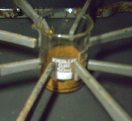 [17th] I dumped some
copper
oxide into some of the new acid and added
some water. There was still some black oxide in the bottom and I left
it and went into town. When I came back it had dissolved, and I set the
beaker of green liquid on the woodstove to evaporate off the water. It
left a brown powder: CuCl2 anhydrous. Turns turquoise in water per
Wikipedia. (Hmm, it didn't take long. When I went to get a picture it
was already dry!)
[17th] I dumped some
copper
oxide into some of the new acid and added
some water. There was still some black oxide in the bottom and I left
it and went into town. When I came back it had dissolved, and I set the
beaker of green liquid on the woodstove to evaporate off the water. It
left a brown powder: CuCl2 anhydrous. Turns turquoise in water per
Wikipedia. (Hmm, it didn't take long. When I went to get a picture it
was already dry!)
I put a little in the cell, into the electrode hole with tweezers. If
it made any differenceto maximum currents it wasn't apparent. Maybe
I'll try more some time.
 Vibrating Electrode Powders Into Graphite
Felt
Vibrating Electrode Powders Into Graphite
Felt
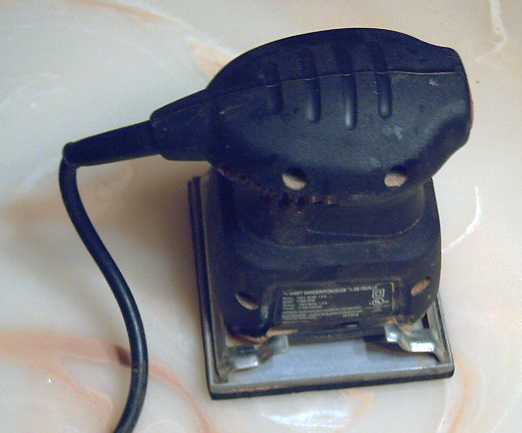
In town I chanced across a woodworker, Gary. He had an old vibrating
"1/4 sheet palm sander" that he didn't use any more (having two newer
ones). I bought it for 10$.
At the Farmers Market I had a talk with Neil, member of an
off-grid farming family, about batteries and someone he knew in
Tennessee who made diesel fuel from wood with graphene as a waste
product. The graphene was supposed to be 10 times as conductive as
copper and when Neil had seen the plant (10 years ago now), they were
trying out conductive plastic for 3D printing and using the graphene
for circuit breaker contacts.
It sounded like it might be a good replacement for
conductive carbon black or graphite powder to improve conductivity
inside the electrodes.
I got a contact name. "Proton Energy".
(But the question is: What is actually causing low current rates in my
cells? Does it have anything to do with the conductivity of the
electrodes? Or is it the electrolyte? or what?)
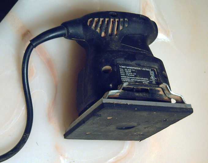 Another view
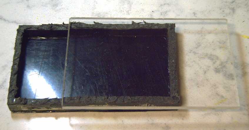 In the
evening
I made an ABS box to mount onto it. Basicly it was my battery cell box
with no terminal openings. For a lid I saw a 1/4" thick piece of
acrylic plastic that just needed one cut to fit it - a clear lid!
In the
evening
I made an ABS box to mount onto it. Basicly it was my battery cell box
with no terminal openings. For a lid I saw a 1/4" thick piece of
acrylic plastic that just needed one cut to fit it - a clear lid!
Weatherstripping foam around the edges should keep it
closed. (If it's not sealed, this is likely to be a very dusty
operation.
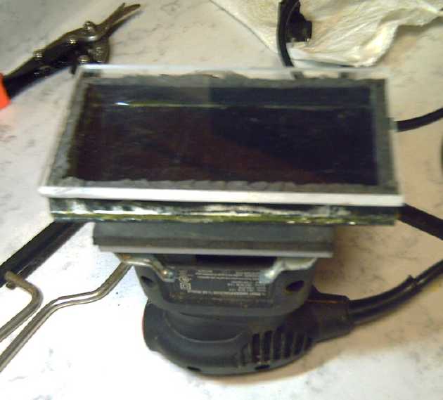 The box on the "vibro"
I'll mount it this way up in the big vise, with the box level.
It'll need some special little C-Clamps to hold the box in place.
 Loading the box: conductive
felt plus active
electrode powder.
Loading the box: conductive
felt plus active
electrode powder.
Assuming it works well,
there will need to be two boxes and lids, one for minus 'trodes and one
for plus, so as to not cross contaminate them. I'll know when I've
tried one whether to make the second or if the idea doesn't work well.
[18th] I started thinking that zinc is known to perform really well,
while manganese is still poorly tested. It would seem I could now make
a nickel-manganate zinc cell, and I had the zinc electrode in the
drawer. I could try impregnating one felt with the positive mix and put
together a cell. Hopefully it would perform better than
previous attempts with the graphite felt to improve conductivity in the
positrode, and maybe some copper chloride in the electrolyte?
I dissolved the SDBS in some water and painted it
onto/into a piece of the watercolor paper separator. It absorbed it
all. Then I went to bleach the nickel & manganese powder. The 100
gram jar of it needed somewhere over 1/4 liter of water, and I used 1/2
a teaspoon of bleach. Then I tried to stir it and it was still full of
lumps of the dry cell manganese. It took quite a while. If I ever use
dry cell MnO2 again I'll be sure to crush it up well into powder before
I mix it in with anything else. Finally I had a jar of soaking wet
stuff. If I poured it through a filter the nano-fine powders would have
clogged the filter after about 3 drops of water. I waited over an hour
for it to settle and poured off only 75cc of water - surely only 1/4 of
it, leaving a slurry. Evidently diluting out soluble impurities from
the loose substance was going to be a tedious process taking a coon's
age! My next solution will simply be to do a lot at once - maybe 1/2 a
kilogram at a time?
I spooned out a bunch into an ashtray and set that to dry
on the woodstove. Obviously it will have to be dry, loose powder to
impregnate into the graphite felt and I wanted to get on with it. I
could (I trust) dilute out impurities after the cell is formed. For the
rest, I filled the jar with water again for further dilution.
[19th] I dumped the dried +trode substance in the glass mortar and
turned it back into loose powder with the pestle. I weighed a sheet of
graphite felt: 3.7g. I put it in the box and spooned some of the powder
on top. There were a few annoyances, but I got it done. One was that
the clips I put on vibrated loose and the box started sliding out one
end. I ended up putting on four 2 inch C-clamps, which got it done but
also kept vibrating loose. Finally, one end of the felt lifted and was
at the top of the box against the lid, so the powders were going
through underneath. I'll have to improve everything before next time -
probably bolt the box onto the sander and screw the lid closed.
It ended up weighing 8.9g, so just 5.2 grams of powder went in. At 200
mAH/g, that's only about one amp-hour. Good enough for a test, but
needs improvement. I'm wondering if there's a more porous graphite felt
or foam around (Hmm... didn't Leonardo say something about "graphite
foam" quite some time back? Must check through my old newsletters.)
Another thought... Maybe I should use two layers of
graphite felt? Uncompressed they would be 2 x 4mm = 8mm thick, but they
would be squashed down quite a bit when clamped in a cell. I decided to
try that. I didn't weigh the second foam (oops) but I'll estimate the
two together would be very close to 7.5g. With the powder they were
only about 14.5g, so there was only about 7g of powder in them. I
spooned some more on top of both and spread it around, figuring that if
the extra powder was just a thin layer, the conductivity should be
pretty good... as long as both graphites touched each other somewhere.
I think I added around 10 grams. 17 grams of powder at 200 mAH/g should
be over 3 amp-hours.
My initial thought was have tabe on the felts and use them
as the terminals. Then I thought the conductivity should be much better
if the whole felt was again a piece of metal and the terminal tab was
metal. So I cut the tabs off the felts and prepped the already cut
cupro-nickel piece by cleaning it and brushing on calcium oxide.
I put it in the cell and put the loaded felts on top of
it. This nearly filled the 10mm thick (inside measure) cell.
I then prepped a separator paper. I had already soaked it
with varsol and dried it. I now mixed the SDBS with some water and
brushed it onto/into the paper. Then I brushed on some zircon. I put
the wet paper into the cell where it slightly folded up the sides, and
placed the zinc plated copper foil electrode into the "bowl" thus
created. Then I took another piece of paper, painted it with zircon,
and put it on top of this electrode. When I pressed down, I estimated
that just about one more sheet of paper would fit as the positive
electrode compacted and everything was pressed together. So I added one
more, no treatment.
Then I went to make the external clamp. I didn't see any
very ideal pieces of alume and I ended up driving into town and
arranging to buy a 4 by 8 foot sheet of 1/4 inch thick alume (that was
probably 1/4 used/gone) from Steve. He also had a small piece that I
took with me to use, and I made the clamp set in the evening, four
#10-24 bolts on each side. It seems to me that for this size cell,
fewer would provide insufficient electrode compaction.
I filled the cell with water through the terminal holes on
the top. At least what I put inside wasn't too thick, because the cell
didn't leak - no water came out the bottom or sides. (If it was too
thin, the compaction would be less and reduce the efficacy of the
posode.)
Charging, Diluting Out Impurities
I started charging it, and then remembered that I had
intended to dilute out any impurities by placing the whole cell under
water. I had a plastic jar just big enough when filled to the brim. I
had put around 30cc of electrolyte into the cell. I now filled the jar
with maybe 1500cc or more. That's 50 to 1 dilution. I dumped in my
little jar of purified KCl salt. It seemed to be enough for charging
the cell through a10Ω resistor from 2.25V. It started around 75mA for a
while at 1.5V. By the morning of the 20th it was 1.8V and below 50mA. 3
hours later it had progressed to 1.85V, 38mA.
Of course the zinc was already metallic, already charged.
So all the while little bubbles of hydrogen were floating up from the
terminal holes. This was the reason for charging so slowly: the gas has
to escape without building up and damaging things inside. Of course it
would be much better if both electrode started charged or discharged
instead of one of each. Zinc hydride is bound to be forming in the
negode.
[23rd] Voltage just stayed around 1.87 to 1.89. I finally thought to
plug the terminal holes to keep air out.
Then I took apart the smaller cell and cut the tape
wrapping off the pair of electrodes. I put the positive side back in,
but I made a new negative with the manganese powder mix impregnated
into a graphite felt. This time I just rubbed the powder into the felt
with the spoon, both sides. The felt went from 2.9 grams to 9.4 grams,
so 6.5 grams of the powder, which was 70% Mn element so 6.5g * .7 * 976
mAH/g = 4.44 amp-hours worth.
I connected the power supply to the 1/2 new cell and set
it to 2.7 volts. The cell sat there grinding away around 1.4 volts,
flipping up and down a bit at random, but gradually the voltage started
dropping slower when the charge was removed. And gradually it rose -
1.42 - 1.46 ...
[24th] The new Mn cell voltage wasn't rising. The separator paper had
looked a bit narrow and I feared it hadn't quite covered the gap at one
edge. Finally I took it apart and put in a new separator paper, cutting
it so all four edges folded up against the ABS cell walls and cutting a
bit off the edge of the graphite foam so the electrode fit easily into
the paper "saucer" thus formed. The voltage started rising into the 2.2
to 2.3 volt range. I ran into town to do a couple of things, fed the
chickens and then locked them up at dark. (The raccons would get them
for sure if I forgot. Their tracks in the snow show they've been
checking out the coop at night.) Then I went out to dinner - a small
party with some interesting discussions.
[25th] Christmas! I phoned relatives and did some reading, then I got
back to it mid afternoon. Load tests showed that the -Zn cell wasn't
improving. (Thankfully, with all the intended "perpetual making"
ingredients included in this one, it wasn't deteriorating either.)
The -Mn cell had reached 2.3x volts but didn't seem to be
rising further in any hurry. I recall them charging to 2.6 volts, even
2.7 in tests years ago.
Finally I decided I must be being too timid in charging.
While starting out with low currents is probably necessary or at least
very desiriable, with 10 ohms in the charging circuits, the current
dropped as the voltage rose, and perhaps there was a point where the
current was failing to convert any more of the NiOOH and MnO4 into
nickel manganates? Then it might go on indefinitely without further
charge going into the cell - just being dissipated as a bit of heat.
There at least was a theory to explain the perplexing lack of
performance of my cells.
So I tried smaller resistors. I ended up with none on the
Zn cell and 1.5Ω on the Mn. Of course the Zn cell rose quickly to the
power supply voltage. The current soon dropped from 490mA to 200, later
to 70. The Mn's voltage started working its way up, now slowly rising
through the 2.4x volt range at 120mA.
I had to keep moving my Fluke DVM between the two cells.
It's the only meter I have that goes above 1.999 volts without losing
the last digit.
New -Mn cell fails
The new -Mn cell
just wouldn't charge. I finally concluded
that my "metallic -Mn electrode" mix wasn't working. Perhaps the
antimony oxide isn't as effective as the sulfide? I still couldn't find
the antimony sulfide (Sb2S3). (I'm not aware that I'm missing any other
battery chemicals that I moved here with, and can't even imagine where
it might be.) I did find an ointment jar of mixed -Mn electrode
powders. It had the antimony sulfide but no zirconium silicate, so it
was probably the original mix I had used in 2012(?) before I found the
need to also add ZrSiO4 for the Mn to stay metallic in the electrolyte
in warmer weather. I could add a few grams of that and use it instead
of the present mix?
Then maybe I should get on e-bay and find some more
Sb2S3. Yikes! The only seller there says 'won't ship to BC Canada'!
"Black powder." (The Sb2S3 oxide is white.) I could buy some "stibnite
mineral" with the long thin crystals of Sb2S3. Maybe I'll search again
for mine, but it's sure a puzzle why it isn't in with all the other
battery experiment chemicals.
(Later I looked back at old TE News issues and found I had
noted graphite powder causes discharge of -Mn electrodes. I had used
zinc powder instead. Maybe the antimony oxide does work okay? I'll try
again with the mix having antimony sulfide - known to work once upon a
time.)
[26th] I charged overnight with 2.25V through 1Ω. The cell hit almost
2.2 volts - seemingly a little higher every day. The usual morning
discharge test through 20Ω got interesting. I had been ending the tests
when the voltage dropped to 1.5 or 1.4 volts. This one started similar
to others, 2.058 volts dropping to 1.912 in 30 seconds and 1.868V after
just one minute. Thereafter it was losing the usual disappointing 10's
of millivolts per minute. But a little above 1.4 volts the drop per
minute slowed considerably to below 10. Then it went to 4: 1.408 to
1.404 to 1.400. I decided to go further. That drop slowed further to 3
mV/minute. I stopped after 31 minutes at 1.370 V. It recovered
gradually to 1.75V.
It surely could have gone about 55 minutes before it
dropped below 1.3 volts - and that's if the rate of drop didn't slow
still further, which it likely would have. And then over 1/2 an hour
above 1.2 volts. That would put it well over 100 mA-H of energy at what
is at least useful voltage levels. (I wasn't willing to stand around
watching for so long.) If that seems pitiful - and puzzling - when
compared to the several amp-hours of theoretical potential, at least
it's a lot more than "Gosh, it lights an LED!"
I put the cell back on charge at 2.25V no resistor.
Perhaps more days of stronger charging will get it delivering such
currents or more at higher voltages?
After less than 2 hours the charge current was down to
50mA and I ran another 20Ω load test. It started with voltages just a
little higher than any previous test but dropped slightly faster, and
ended up almost exactly where the the morning test had been, one minute
shorter to 1.370V, again dropping just 3mV/minute once it was down to
1.40V. But it seems to be long (overnight) charging with no resistor
that brings actual improvement in performance and reduces the rate of
self discharge, bit by bit.
But the 3+ amps of momentary short circuit current - only
30mA/sq.cm - hadn't risen. (It should easily be double that if not
triple or quadruple.) It dawned on me that the problem with that - and
a reason for low discharge voltages - may be that the osmium doped
layer on the zinc is still from the batch I made in ... what? ... 2011?
I had to resurrect it a couple of times by adding water to it, and now
it's about gone. And the osmium in it must have been pretty diluted
too. High time for a new batch!
Oh, wait... I found the original little spice bottle of
acetal ester (if that's really what I made) with no osmium added to it.
It too had dried out and I had to add water. Then I added a bit of the
precious osmium powder. Hopefully that would be good enough. I opened
up the cell and painted it onto the zircon and zinc of the electrode.
And here was something else to notice: recently I had just
used a sheet of zinc in the smaller cell. When I took it out, it was
totally fused to the separator paper. No doubt it was growing dendrites
through it. With this properly prepared cell and electrode, the
electrode lifted off the separator without even trying to stick. No
dendrites into the SDBS impregnated paper!
When I reassembled it the cell said baout 1.8 volts. I put
it back on charge, 2.25V no resistor. Currents seemed higher.
The -Mn Cell: what's next?
For the other (-Mn) cell I found a jar of -Mn powder mix
from long ago, probably early 2013 since the ingredients list didn't
say "zircon". It also didn't show a TE News issue to tell me when I had
made it (again saying it was an early one). It had the Sb2S3, so if I
add ZrSiO4 it should work. It felt heavy - surely enough to
last through a few experimental cells.
I searched through a couple of old TE News battery
writeups like #53 looking for it and discovered that I had found out a
lot of the required battery/chemical info back then, that I had had to
rediscover again much later after leaving the project sit much too
long. Back then it was new, scattered info and I hadn't got some of it
properly sorted out and organized in my mind, so it got forgotten.
Amazement Strikes! (back to testing -Zn cell)
At 9 PM I started another load test, the same with 20Ω
load to compare. Once more the voltage started out a little higher than
any previous time (2.121 just before starting, 1.980 V after 30
seconds), and it dropped a little faster each minute to match. But
after 1.404 volts, the next minute (26) saw only a 1mV drop instead of
8 or 10. The next minute it went up a millivolt! And it
continued up a millivolt per minute until it hit 1.410 V, then it
resumed a similar slow drop. I checked the current meter and it was
consistent with the voltage and 20 ohms. In fact it was another 15
minutes (minute 41) before the voltage dropped under 1.400. Then it
started dropping at just 2.5 mV/minute. Naturally I let it finish
running for a whole hour, at which point the voltage had just dropped
to 1.349.
Whether the improvements were from the second coat of
osmium or more charging or both, I now had something behaving under
load (albeit a fairly light load) much more like a real battery! And
not deteriorating but improving. Of course I now look forward to seeing
it do the same delivering higher discharge voltages or running heavier
loads.
[27th] It started meeting this expectation/hope. Overnight the charge
current had dropped to around 30mA instead of to 50 or 40. (The useless
power supply ampmeter only goes to the nearest 10mA, and even at that
it reads 20mA lower than actual.) The morning 20Ω load test started out
a little lower voltage than the previous two tests, but the drop each
minute was a little less, and after 12 minutes the voltage was higher
than on any previous test. After 25 minutes - the same time as
previously - it commenced dropping by only 1 to 2 mV/minute at over
1.47 volts instead of just over 1.40. Then it sped up to 3 mV/min as it
went through the 1.46 to 1.35V range. next reading after 1.350V was
1.346 and I stopped there. But that was at the 68 minute mark, up from
60 minutes last time. Initial voltage recovery, while still agonizingly
slow, was a little faster, hitting 1.461 instead of 1.453 after one
minute, but it slowed down and was behind after 15 minutes. After half
an hour it was at 1.674V.
MnO2 + Zn as in non-rechargeable dry cells either salt or
alkali, is around 1.5V. NiOOH + Zn is more like 1.8V. I'm expecting
NiMn2O4 + Zn to be almost or about 2.0V. Allowing for drop under load,
the lower voltages seen except for the initial few minutes of discharge
suggests that only a fraction of the MnO2 + NiOOH has been converted to
NiMn2O4 and similar double spinel salts so far. The fact that the
readings keep improving suggest that it is nevertheless happening. It
seems to be that much "excess" charging beyond what a fully working
battery would normally need is very gradually converting them. I think
maybe I'm still too timid on the charging - I'll try upping the charge
voltage just a little... I set the very touchy dial to 2.313 volts. (If
there were 6 cells for 12 volts, that would be equivalent to just 13.9
volts - not a super high charge at least for lead-acid.)
After just an hour of charge a 15 minute 20Ω load test
showed the voltages starting higher and dropping a bit faster but
staying higher through this short period. Next I'll compare that to a
longer charge.
I'm not sure how watching, marking down and studying such
minutely improving figures for hour after hour can be so fascinating,
but the gradual improvement suggests this cell is forming into a
practical working battery rather than a test unit that just doesn't cut
it for actual use. That's the exciting part! It can now be duplicated
or further improved, instead of just "sort of" having it work
"something like a battery". If it doesn't unexpectedly deteriorate.
And can I find NiMn2O4 powder to buy, or find a fast way
to make it before putting it into the cell? Let's see, from the web...
one way (typical) is to mix and heat the powders [Ni(OH)2 + MnO2] to
1200°C in air. But the paper complained about the purity of the
result. (Would 800° work?) Oh Dang! I forgot to torch this
electrode! Another way is probably to bleach it. Perhaps I diluted the
bleach too much when I mixed the powders, or didn't use enough. Oh...
and I now think to refill the cell. I keep adding bits of water, but
nothing leaks out the bottom, and it always absorbs in instead of
sitting in the terminal hole. That probably means it's using up water
in the reaction to form the nickel manganates.
Some Oxidizers:
1. High Heat (in air)
2. NaClO - Bleach
3. KMnO4 - Potassium Permanganate
4. A battery positive electrode under charge.
A further thought [evening 28th]: If I expect oxidizing MnO2 and NiOOH
to produce nickel manganates, does it not also follow that reducing the
manganates will result in them turning back into the original
substances? And then into Mn2O3 and Ni(OH)2? Perhaps I shouldn't be
driving the cell down to such low voltages in the discharge tests?
Maybe if I stop sooner the cell will improve more rapidly?
(Nevertheless, it continues to improve.) I think I'll stop at 1.4 V
from now on, if not 1.45 or 1.5. or even 1.6. That will at least
initially make for short load tests delivering even fewer amp-hours,
but the voltages may improve more rapidly and start giving seriously
better results after a few days.
I am much amazed how long this whole process is taking. I
almost think the plus side should be immersed in electrolyte with a
dummy graphite electrode for the negative, which can bubble as much
hydrogen as it wants until the positive has formed up properly, which
seems to take weeks.
---
[Back to 27th] Late in the evening I ran another load test, this time
with 10Ω instead of 20Ω. I had run a couple of these before and they
only lasted a few minutes. This time it did better with higher
voltages. I was going to end it when it dropped below 1.350 V (at 10
minutes), but in the last minute the rate of drop decreased a lot and I
decided to run it down to 1.300 V to see how it would go. Here it
surprised me again. It ran at 1.312V for 3 minutes!, and then rose
a bit to 1.313V for another 2 minutes. It finally dropped under 1.300V
at the 23 minute mark, running for over 3 times as long as previous 10Ω
tests.
[28th] The morning 20 Ω load test was, as was by now predictable, just
a little better than any previous one. Instead of at 1.40 or 1.47
volts, the drops of only 4 or 5 mV/minute started at about 1.5 V. I
stopped it after 53 minutes, declining to run it under 1.400 V. If I
had gone down to 1.350 V as yesterday and assuming a continuing 3
mV/min - which seeing previous runs would probably have decreased - it
still would have run about 70 minutes and been by a bit the longest
run. It also delivered slightly higher voltages/currents/powers.
Similar to yesterday I ran a 10 Ω load test. Instead of
the voltage falling under 1.35 V at 10 minutes, it did so after 15. A
further small improvement! At that point I ended it. It recovered to
1.785 V after another 15 minutes or so, when I put it back on charge.
[29th] With the thought that running load tests down to low voltages
might be deleterious, delaying or even preventing formation of the
desired higher reaction voltage "NiMn2O4+δ"
oxides and hydroxides, I only ran the load test down to 1.600 V. At
least it makes for much shorter tests. Voltages were a little lower
than yesterday morning, but higher than any other previous test and
both fell under 1.6 V at minute 15. (Maybe it was running it down to
1.35 V with 10 Ω last night?)
[30th] I ran several load tests, each more disappointing than the last.
What was going on? I didn't charge overnight, and the next morning the
voltage had dropped to 1.757.
A Whole New Appraisal of Nickel Manganates
[31st] Before I got up I started thinking: According to the
Pourbaix diagrams, at pH 13 nickel oxyhydroxide would have a reaction
voltage probably around +.6 volts. Manganese dioxide would be around
+.25 V. With all those osidation states, I was pretty sure nickel
manganese oxides would have at least double the amp-hours per kilogram
of NiOOH - effectively in practice 180+ instead of 90. I had also been
thinking the reaction voltage would be higher than NiOOH, but really
that was a complete wild card.
What if in fact nickel-manganese oxides had a much lower
reaction voltage than I had been supposing? Before the oxides were
converted, the cell would have the voltage of nickel-zinc, headed for 2
volts as I had been getting. And probably they needed to be that high
in order to convert the oxides. But if the combined oxides reacted at
only, say, -.1 volts, the cell voltage with the zinc (-1.2V) would only
be 1.1 volts. Here I've been confused many times in my battery
research. A cell down near or under 1 volt (which so many seemed to
drop to overnight or in a few days) just didn't compute with me, and I
was giving up on them.
I decided to try a discharge test in this sense. The
disconnected cell had dropped to 1.757V overnight. I connected the 20
ohm load and it dropped to 1.25V in about 15 minutes. That would have
distressed me, but this time I was expecting it. From there it was
dropping only about 6mV/minute until it hit 1.2V, then the drop slowed
to 4, 3 and 2mV/min. It ran another hour dropping to 1.067V, and
continued dropping by just under 2mV/min. At 2 hours and 10 minutes it
was down to .949V - and still going strong.
As the test wore on it headed down to .901 volts after 2
hours, 30 minutes: .9/1.0 * 142 = 128WH/Kg. But when I disconnected the
load, the voltage quickly sprang back to over 1.2 volts (and eventually
to over 1.4V), so maybe the load was a little high for the low
conductivity of the cell, and cells with better conduction (the thing
to focus on next?) might well be rated as a nominal 1.1 volts, so
instead 1.1/1.0 * 142 = 156WH/Kg. This is up into the energy per weight
territory at least of lithium-iron phosphate. (Some very good 300
amp-hour ones I have in the garage work out to 176 WH/Kg.) NiMn-Zn is
of course much cheaper.
I stopped it and went into town. I resumed when I returned
and ran it down to .75 volts at the 3 hours, 35 minutes total discharge
time mark. It pretty much took all day with a break. It recovered to
well over 1.07 volts in a minute, over 1.1V in two, and eventually to
1.450V. It might run another 20-30 minutes before it dropped to .75
again. I think this is longer than any previous load test.
So it seemed that instead of a cell of about 1.7-1.8V as
with NiOOH, or even higher as I had anticipated, I had a cell that
might be rated 1.1V with over double the amp-hours. Thus:
1.1V * (say) 200AH/Kg = 220WH/Kg
instead of:
1.6V * 90AH/Kg = 144WH/Kg
That's the "Plus" side. But it's the heavy side. Zinc is 820AH/Kg. So
instead of 820/144=5.7, we have 820/220=3.7 then 4.7/6.7=.70 or
weighing only 70% as much per unit of energy stored - ignoring water
content, the copper substrate for the zinc electrode, the separator
paper and packaging, which are the same in any case. Maybe it can be
about 80% of the weight (125% energy by weight) of nickel-zinc.
I bought a few nickel-zinc "AA" cells recently. We can compare:
Nickel-Zinc "AA" cells per the label & weigh scale: 2.5WH / 22g =
114 WH/Kg. (This is better than Ni-MH, which maxes out at about (AA:
2.5AH*1.2V/30g=) 100WH/Kg. If only the cells lasted well, zinc would
replace most everything else AAA to D.)
Multiply: 114 * 125% = 142 WH/Kg.
Oh My God! I think I had at least one perfect working cell in 2013 or
2014 - NiMn-Mn! (NiMn2O4+n - Mn) In fact probably 2 or 3 - I just
didn't recognize it. After 3 weeks of charging and testing the load
voltages dropped from 2.4V (nominal, Ni-Mn) down to 1-point-something
(NiMn-Mn) and wouldn't go back up and stay anywhere near 2.4V. I
thought something was wrong with it and gave up!
I went to recharge it again, this time at 1.5 volts. But
at that voltage it drew no appreciable current! Well, why would it if
it had risen to 1.35V all by itself? Wait... now I'm totally confused!
Surely one doesn't need to charge a 1.1 [nominal] volt battery at 2+
volts?
One sheet of
the tedious load testing of the cell. The cell kept
lasting instead of failing, so there was more and more testing.
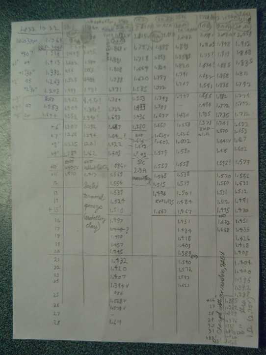 [January
1st] I charged it at 2.2 volts overnight, but it again didn't
hold much charge at higher voltages and quickly dropped below 1.5. I
ran a load test first at 10 ohms, but as it seemed to be overpowering
the cell's capacity, after 15 minutes I switched it to 30 ohms. Voltage
fell fairly quickly until it was under 1.3 volts, but by 1.25 volts it
was only dropping about 4 mV/min. After that it ran over 3 hours
(~3h10m total) down to .898 volts dropping 2 to 3 mV/minute, at which
point I ended it. It immediately jumped up to over 1.1 volts,
suggesting that even 30mA (=.9V/30Ω) was a bit of an "overload", and in
a minute was over 1.2. An hour or so later it was over 1.4V. I had to
set the power supply to about 1.9 volts to get any appreciable amount
of charging current. Why does it recover to such a high voltage and
draw so little current if the "NiMn2O4+x" oxides have been discharged
for over 3 hours? I'll set that aside for the moment and just put up
with using a high charging voltage.
[January
1st] I charged it at 2.2 volts overnight, but it again didn't
hold much charge at higher voltages and quickly dropped below 1.5. I
ran a load test first at 10 ohms, but as it seemed to be overpowering
the cell's capacity, after 15 minutes I switched it to 30 ohms. Voltage
fell fairly quickly until it was under 1.3 volts, but by 1.25 volts it
was only dropping about 4 mV/min. After that it ran over 3 hours
(~3h10m total) down to .898 volts dropping 2 to 3 mV/minute, at which
point I ended it. It immediately jumped up to over 1.1 volts,
suggesting that even 30mA (=.9V/30Ω) was a bit of an "overload", and in
a minute was over 1.2. An hour or so later it was over 1.4V. I had to
set the power supply to about 1.9 volts to get any appreciable amount
of charging current. Why does it recover to such a high voltage and
draw so little current if the "NiMn2O4+x" oxides have been discharged
for over 3 hours? I'll set that aside for the moment and just put up
with using a high charging voltage.
After another discharge test in which in 20 minutes it was
obvious the cell hadn't done much recharging in 7 hours, I raised the
charge voltage to about 1.93V. After a couple of hours it was still
charging... at a whopping 11mA. Let's see... if the discharge (30Ω) is
around 40mA, then 8 hours charging at 10mA will only make for a 2 hour
discharge. For a full charge after a 4 hour discharge could take...
well... all day. And what if it would run for 6 or 8 hours? One load
test per day - for several hours! I already thought all this testing
was tedious! But that's what's wanted: lots of amp-hours! It's
definitely a battery now.
And this time I finally seem to have a cell with a zinc
negative that after two weeks has shown no sign of the zinc growing
dendrites and shorting to the plus side as all my previous cells have
done. This is attributable to the sodium dodecylbenzenesulfonate in the
separator sheet and the osmium doped acetaldehyde/acetal ester painted
onto the zinc electrode.
[January 2nd] After "charging" overnight at such low currents a load
test in the morning was disappointing - better than the previous
evening but not by much. I decided to go back to 2.2 volts. It seemed
silly if the cell was half that voltage, but it didn't seem to take
much current otherwise.
Then I
opened
the cell to inspect it. The graphite felt was ones of ohms resistance -
that can't be the cause of low current capacity. And neither could zinc
with copper behind it. It must be in the electrolyte and or the
separator sheet. I tried to peel the separator sheet from the zinc
electrode. Mostly it was free, but it stuck in a few places mostly
around the edges. This suggests that the SDBS really does work to keep
zinc dendrites from growing into the separator sheet, but that this
separator had a few weak spots where it had penetrated. So in
principle the 150 year old zinc dendrite issue is solved. As this
has been the "holy grail" of battery making for so long, I seem to have
accomplished something valuable. (And it may not have penetrated right
through the paper but been stopped somewhere inside. Certainly there
have been no shorts between electrodes in 2 weeks trials, and in my
experience they seem quick to form.) I pried the paper off and painted
some SDBS on the electrode itself. Next time I'll try adding less water
to the SDBS so it's thicker inside the paper sheet, and be sure the
paper folds up all four edges past the copper/zinc sheet. I also
sprinkled a little KCl electrolyte behind the zinc and added another
piece of paper before I closed it up again so that the graphite felt
would be held more strongly compacted.
On another note, the cell seemed to have finally stopped
absorbing water. It now would sit in a little pool at the electrode
hole where I dripped it in. I guess most of the nickel and manganese
oxides have been converted to hydrated nickel-manganese oxide by now.
Definitely getting higher current capacity is a major goal
now. It might hold answers to the charging voltage question.
100mA/sq.cm (10 amps for this cell) seems like a reasonable minimum to
want. 200 would be more ideal. But first:
Even if there are still some questions and uncertainties,
I want to make a set of
"Exploring Battery Making with Craig" videos on Youtube - "perfected"
or not.
If I do get everything "perfected", will I start producing
batteries? Well, I haven't been producing or selling much of anything
else I've
invented in recent years, so far! How long would it take me to make a
36 volt one (32(?) cells) that I could try out in my DC solar power
system? That would definitely need some speeded up production
techniques from single prototype cell making! Maybe all in a batch or
batches?
Cobalt Oxides
 That evening, having the
"Pourbaix" folder open for something, for some reason I went through
all the redox diagrams and charts of all the elements, backward from
"zirconium" to "Ag" (Silver). I've found none of the info I read is
entirely trustworthy, but The "Web Elements" chart (originally from the
CRC Chemistry
Handbook I believe) for cobalt struck me. It was plain and simple, no
odd "bypass" paths or soluble states. In alkali the voltage from
valence 2 to 3
was shown as just .07 volts lower than nickel.
That evening, having the
"Pourbaix" folder open for something, for some reason I went through
all the redox diagrams and charts of all the elements, backward from
"zirconium" to "Ag" (Silver). I've found none of the info I read is
entirely trustworthy, but The "Web Elements" chart (originally from the
CRC Chemistry
Handbook I believe) for cobalt struck me. It was plain and simple, no
odd "bypass" paths or soluble states. In alkali the voltage from
valence 2 to 3
was shown as just .07 volts lower than nickel.
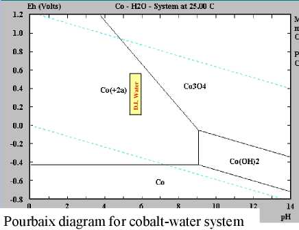 It
was contradicted by a Pourbaix diagram showing much more negative
reaction voltages and only Co3O4 instead of Co(OH)3 or CoOOH. Then in
the "Pourbaix
Diagram Atlas" were diagrams that contradicted both - and each other.
Of course, it all depends on what the voltages are referenced against.
The most common "reference electrode" voltage is the "standard hydrogen
electrode" ("SHE", defined as 0.000V), but there are others. And
voltages may also depend on the electrolyte.
It
was contradicted by a Pourbaix diagram showing much more negative
reaction voltages and only Co3O4 instead of Co(OH)3 or CoOOH. Then in
the "Pourbaix
Diagram Atlas" were diagrams that contradicted both - and each other.
Of course, it all depends on what the voltages are referenced against.
The most common "reference electrode" voltage is the "standard hydrogen
electrode" ("SHE", defined as 0.000V), but there are others. And
voltages may also depend on the electrolyte.
I remembered reading
some
still
different info info about cobalt, in connection with Ovshinky's flooded
nickel [oxyhydroxide] / metal hydride EV batteries of the late 1990s. I
looked in my old printed notes and found (from a website that no longer
exists) CoOOH + H2O) + e- <=> Co(OH)2 + OH- @ +.17 V. This is
more what I remember reading, rather than +.42V. or '-'anything. OTOH,
if one is using nickel manganates of
an indeterminate but likewise very low voltage, cobalt oxides might
well be
better. Nickel and cobalt have virtually identical atomic weight, so if
nickel hydroxide has a theoretical 289 AH/Kg for the same reaction
[NiOOH <=> Ni(OH)2 @ +.49V], then cobalt must too (works
out to
288 AH/Kg).
I also remember reading that cobalt oxide added to nickel
oxide makes the mixture more conductive, but that the cobalt adds
little to the energy storage because of its low reaction voltage. This
makes sense not because cobalt has no energy but because it will remain
in its more oxidized state until the cell is considered "discharged"
and cell resistance has risen, so the cobalt oxide itself won't work
well in that cell.
With a lower reaction voltage, why might cobalt be better
than
nickel? For one thing, with that voltage it's more likely to convert
more fully, where Ni(OH)2 won't all convert to NiOOH, and if most of it
converts to the Ni(OH)2 during discharge, the electrode resistance goes
way
up, making it hard to recharge. So the nickel valence really goes from
somewhere around
2.25 to 2.85 (~~) rather than from 2 to 3. (That a reduction to 60%
of theoretical right there.) The cobalt oxides will probably go closer
to full conversion. Then, Ni(OH)2 is 'fluffy' (low density), and low
conductivity. It needs strong compaction as well as more additives to
help
it conduct, which add
non-reacting weight. One common additive is (ta-dah!) CoOOH / Ca(OH)2!
(as mentioned)
So
in practice the nickel attains only around 90 AH/Kg. Co(OH)2 OTOH is
dense, heavy and (obviously) must be much more conductive. A little
graphite
might be all the conductivity additive it needs? It might well achieve
an actual, practical 200 AH/Kg. A cobalt-zinc cell should be about the
same voltage - and in by the numbers 97% as high watt-hours capacity by
weight - as a manganese-zinc cell, usually stated as 1.5 volts but by
rechargeable battery standards might be considered a 'nominal' 1.3
volts. And manganese-zinc
alkaline 'D' cells [non-rechargeable] can be over 150, or even hit 200,
WH/Kg - lithium territory.
Cobalt oxide isn't so rare. On a chart it seems to be half
as plentiful in the Earth's crust as nickel and copper, and 100 times
as common as silver, which has also been used in batteries. I thought I
had a minute amount from the pottery supply from 2010 or so and I found
the container. It actually had plenty to make some test cells without
having to order more. With zinc seemingly working well and nickel
manganese oxides seeming to have a steep voltage slope in their
discharge curve, I think I'll try out the Co-Zn combo!
(A chart says cobalt is around 1/3 as abundant in the Earth's crust as
copper and nickel and 100 times more abundant than silver - which after
all has been used in batteries. Looking at prices it's only 1-1/2 times
as costly as nickel oxide. At the cheapest US ceramic supply I find
it's 38 $US, who also have nickel oxide at 25 $US)
Later, a web search revealed many more cobalt Pourbaix
diagrams, and they varied a lot. Some (like the one shown above) were
simply incomplete. The oxidation state (b) Co3O4 is intermediate
between (a) Co(OH)2 and (c) CoOOH, and the reaction voltage
(a<=>b) is either almost the same as or very different to
(b<=>c).
I guess I should just pick the diagram that looks the most
promising? That one shows about +.24 and +.26V at pH 13, suggesting
Co3O4 will be a transition molecule little found in the cell between
charge and discharge. The other diagram shows -.15 and +.4V. Losing 2/3
of the amp-hours to gain .15 volts... or losing .4v and 1/3 of the
amp-hours... would be most undesirable. I think only trying it will
tell what is really going to happen.
A highest oxidation state is CoO2 at around +.7 to +1
volt, but I suspect the electrode would bubble oxygen instead of
attaining that state.
Since I'm not getting this report posted until the 8th,
this is trespassing far into January. Something to try out - next
report!
My
Solar
Power System
Wutz in a Name?
The term "solar panel" is
rather long at four syllables. "Panel" can mean just about anything,
including the electrical panels used with solar panel installations, so
it is confusing. I note that some solar panel installers/makers/et al
have gone from calling them "panels" to the equally ambiguous term
"modules". (Really just muddles?)
Surely we can come up with something distinctive and
shorter - 2
syllables? One has to find something at least relatively unambiguous
that might catch on by being close enough to the original words to
readily understand as well as being descriptive. "solari?" hmm...
sounds like a unit of measurement. Maybe the start and end, "solnel"?
Hmm... yuk! The start of both words, "solpan"? Hmm... the "L" before
the "P" is a bit hard to say. How about "solan"? "sopan"? "sopnel"?
"spanel"? "solie"? Hmm, I think I sort of like that one! A solie, two
solies. And a "solie system" is less ambiguous than a "solar system".
Let's see if I still like it if I write it down a few times... Nah,
let's try "solari" after all? One solari, two solaris. And a solari
system? How about "sundows" - sun windows? "Sunnels?" "Pvanels" (for
solar "PV")?
After trying some out for size, in the end I didn't really
like any of the terms I could think of and was pretty
sure no one would adopt one.
The Usual Daily/Monthly/Yearly Log of Solar
Power Generated [and grid power consumed]
(All times are in PST: clock 48 minutes ahead of local sun time, not
PDT which
is an hour and 48 minutes ahead. (DC) battery system power output
readings are reset to zero
daily (often just for LED lights, occasionally used with other loads:
Chevy Sprint electric car, inverters in power outages or other 36V
loads), while the
grid tied readings are cumulative.)
Daily Figures
Notes: House Main
meter (6 digits) accumulates. DC meter now
accumulates until it loses precision (9.999 WH => 0010 KWH), then is
reset. House East and Cabin meters (4
digits) are reset to 0 when they get near 99.99 (which goes to "100.0")
- owing to loss of second decimal precision.
New Order of Daily Solar Readings (Beginning May 2022):
Date House, House, House, Cabin => Total KWH Solar [Notable
power
Uses; Grid power meter@time] Sky/weather
Main
DC East Cabin
November
30th 4160.77, .88, 50.49, 61.58 => .10
[2237@16:30] -4° overnight, ~ -3 all day.
December
01st 4160.91, .95, 50.86, 61.61 => .61 [2286@17:30]
-6.5° in AM. I brushed some snow off lawn solaris - probably why
the
house system gave anything much at all (unlike yesterday.)(But still
ice on them - melted on 2nd.)
02d 4161.48, 1.04, 52.41, 61.84 => 2.44 [2319@17:00] -1°.
Still icy snow on shallow angle roof solaris (10 of 18 solaris).
03rd 4163.00, 1.15, 54.26, 62.57 => 4.21 [60Km; 2357@17:00] Sunny.
-4.5 last night. Snow on solaris turned to ice - more transparent.
04th 4165.21, 1.28, 56.06, 63.78 => 5.35 [2405@16:30] Ice on solaris
turns to frost overnight.
05th 4167.40, 1.40, 57.87, 64.87 => 5.21 [50Km; 2444@17:00; 50Km]
Sunny yet
again, but still cold. -3°, -1°. Solaris clear.
06th 4168.60, 1.49, 59.06, 65.72 => 3.33 [2492@16:30] Less sunny.
07th 4169.31, 1.57, 59.44, 66.04 => 1.49 [2532@16:30; 55Km]
08th 4170.81, 1.65, 60.54, 66.70 => 3.34 [2572@16:30]
09th 4171.41, 1.72, 60.83, 66.92 => 1.18 [85Km; 2612@17:00] Some
snow flakes
10th 4173.46, 1.82, 62.47, 68.07 => 4.94 [55Km; 2664@17:00] Sunny.
11th 4174.77, 1.90, 63.81, 68.78 => 3.44 [2704@17:00]
12th 4175.00, 1.99, 63.87, 68.88 => .48 [55Km;
2743@16:30; 35Km]
13rd 4176.05, 2.06, 64.55, 69.45 => 2.38 [2789@16:30]
14th 4178.10, 2.16, 65.90, 70.39 => 4.44 [55Km; 2827@17:00] Sunny
3° (warmer)
15th 4179.71, 2.24, 67.27, 71.28 => 3.95 [2873@16:30] heavy jet
trails across sky in AM, then sunny
16th 4181.39, 2.34, 69.04, 72.54 => 4.81 [2894@16:30] Sunny
17th 4183.39, 2.45, 70.85, 73.49 => 4.87 [2928@16:30] Mostly sunny
18th 4183.54, 2.51, 72.07, 73.55 => 1.44 [2980@17:00] Som sun later
in PM. -5° all day, late eve. -6°. Snow on solaris except steep
angle ones: carport/pole.
19th 4183.56, 2.52, 72.19, 73.57 => .17 [3026@16:30; 55Km]
-7° all day.
20th 4183.68, 2.59, 72.61, 73.63 => .67 [3098@17:00]
10° AM; -8°, -9°. (72 KWH!!! Electric heaters in garage,
set to 5°, must have been running.)
21st 4183.92, 2.71, 74.11, 73.77 => 2.00 [3141@16:30] -11° in
AM!!! At midday I brushed the snow off the solaris on the the lawn.
(Why
didn't I think of that when it first snowed?)
22d 4183.93, 2.74, 74.16, 73.79 => .11 [3184@17:00]
-.5°. Way warmer but --- SNOW!
23rd 4184.03, 2.86, 74.23, 73.91 => .41 [3223@17:00] +2 to
+3° Wind, rain.
24th 4184.27, 3.02, 74.39, 74.06 => .71 [60Km; 3261@17:00;
10Km] +4°, rain - snow melting, slush
25th 4184.51, 3.12, 74.46, 74.19 => .54 [3300@16:30]
+6.5° wind, rain, snow mostly gon.
26th 4186.18, 3.28, 75.41, 74.85 => 3.44 [3333@17:00] rain AM; some
sun PM. Froze in evening.
27th 4187.51, 3.42, 76.73, 75.64 => 3.58 [3360@16:30] Some sun.
Frost stayed all day.
28th 4189.59, 3.52, 78.49, 76.76 => 5.06 [3391@16:30] Sun! Still
frost.
29th 4190.47, 3.62, 79.12, 77.20 => 2.05 [45Km; 3430@16:30]
30th 4190.90, 3.75, 79.16, 77.27 => .67 [90Km;
3484@22:30]
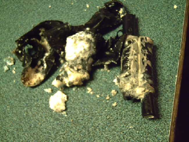
Bad neutral line wreaked havoc on
electrical system - 95VAC on
one line, 150VAC on the other. (Flickering lights. Blinking clocks. I
thought my belt sander and microwave oven had both quit. I faintly
smelled burnt electrical wires in garage - hope nothing is burned out.)
Had to call BC Hydro. Worker replaced all three connectors at the top
of my mast. Neutral especially was correded away with lots of alumina
powder. Ground fault
breaker to carport & cabin was off most of the day.
(Asked & found out main
transmission line here is 14,400 V.)
31st 4191.82, 3.99, 79.95, 77.93 =>
2.51 [55Km; 3503@16:30] 6°.
January
1st 4192.15, 4.12, 80.43, 78.27 => 1.91 [3544@16:30] Wind storm.
2nd4193.56, 4.23, 81.07, 78.75 => 2.64 [60Km; 3583@17:00] Calm.
6°
3rd 4193.97, 4.33, 81.26, 78.93 => .88 [3622@17:00] Cloudy,
then stormy again. Trouble with water filter tank.
4th 4194.83, 4.33, 81.61, 79.24 => 1.52 [50Km; 3670@17:30] DC system
was deprogrammed & disconnected by spray of water from filter tank.
(And car balance charger has been soaked & messed up.)
5th 4195.23, 4.33, 81.69, 79.36 => .60 [3702@17:30] Dark,
clouds, rain
6th 4195.88, 4.33, 81.94, 79.60 => 1.14 [90km; 3743@17:30] Mor ov
same
7th 4197.16, 4.33, 82.62, 80.10 => 2.46 [55Km; 3788@17:00]
Chart of daily KWH from solar panels (Solaris?).
(Compare DECEMBER 2022
(left) with November 2022 & with December 2021 - but note number of
solar
panels differs from 2021.)
Days of
__ KWH
|
December 2022
(18 solies)
|
November 2022
(18 solpans)
|
December 2021
(14 solar panels)
(2 doing not much!)
|
0.xx
|
9
|
7
|
17
|
1.xx
|
3
|
1
|
9
|
2.xx
|
5
|
4
|
4
|
3.xx
|
6
|
5
|
1
|
4.xx
|
5
|
4
|
|
5.xx
|
3
|
1
|
|
6.xx
|
|
4
|
|
7.xx
|
|
2
|
|
8.xx
|
|
1
|
|
9.xx
|
|
1
|
|
10.xx
|
|
|
|
11.xx
|
|
|
|
12.xx
|
|
|
|
13.xx
|
|
|
|
14.xx
|
|
|
|
15.xx
|
|
|
|
Total KWH
for month
|
79.97
|
114.91
|
32.98
|
Km Driven
on Electricity
|
829.9 Km (Od: 91058)
(135 KWH?)
|
793.1 Km
(~120 KWH?)
|
793 Km
(~120 KWH?)
|
Km = Nissan Leaf electric car
drove distance, then car was charged.
Things Noted - December 2022
* Nothing except notes day by day above.
Monthly Summaries: Solar Generated KWH [& Power used from
grid KWH]
Month: House system (+ DC system at house) + Cabin system = KWH made
[used from grid]
2019
March 1-31: 116.19 + ------ + 105.93 = 222.12 KWH - solar [786 KWH
used from
grid] (10 solar panels
total)
April - 1-30: 136.87 + ------ + 121.97 = 258.84 KWH [608 KWH]
May - 1-31: 156.23 + ------ + 147.47 = 303.70 KWH [543 KWH] (11th
solar panel connected on lawn on 26th)
June - 1-30: 146.63 + 15.65 + 115.26 = 277.54 KWH [374 KWH] (36V, 250W
Hot Water Heater installed on 7th)
July - 1-31: 134.06 + 19.06 + 120.86 = 273.98 KWH [342 KWH]
August 1-31:127.47 + 11.44+91.82+(8/10)*96.29 = 307.76 KWH [334 KWH]
(12th solar panel connected
on lawn Aug.
1)
Sept.- 1-30: 110.72 + 15.30 + 84.91 = 210.93 KWH [408 KWH]
(solar includes 2/10 of 96.29)
Oct. - 1-31: 55.67 + 13.03 + 51.82 = 120.52 KWH solar
[635 KWH used from grid]
Nov. - 1-30: 36.51 + 6.31 + 26.29 = 69.11
KWH solar [653 KWH used from grid]
Dec. - 1-23: 18.98 + .84* + 11.70 =
31.52
KWH, solar + wind [711 KWH + 414 (while away) = 1125 from grid]
2020
Jan. - 6-31: 17.52 + ------* + 10.61 = 28.13 KWH,
solar+ wind [1111 KWH from grid]
Feb. - 1-29: 56.83 + ------* + 35.17 = 92.00 KWH,
solar + wind [963 KWH from grid]
* The solar DC system was running the kitchen hot water
tank. Now it's only running a couple of
lights - not (usually) worth reporting. So there's just the 2 grid tie
systems:
house and "roof over travel trailer" (AKA "Cabin").
One year of solar!
March - 1-31: 111.31 + 87.05 = 198.37 KWH solar total
[934 KWH from grid]
April - 1-30: 156.09 + 115.12 = 271.21 [784 KWH
from grid]
May - 1-31: 181.97 + 131.21 = 313.18 KWH
Solar [723 KWH from grid]
June - 1-30: 164.04 + 119.81 = 283.82 KWH Solar [455 KWH
from grid]
July - 1-31: 190.13 + 110.05 = 300.18 KWH Solar [340
KWH from grid]
August- 1-31: 121.81 + 83.62 = 205.43 KWH Solar [385KWH
from Grid]
Sept. - 1-30: 110.68 + 65.09 = 175.77 KWH Solar [564
KWH used from grid]
Oct. - 1-31: 67.28 + 42.55 = 109.83
KWH Solar [1360 KWH from grid -- Renters!]
Nov. - 1-30: 35.70 + 20.79 = 56.49
KWH of Solar [1301 KWH from grid]
Dec. - 1-31: 19.78 + 11.31 = 31.09
KWH Solar [1078 KWH used from grid]
2021
Jan: 25.47 +
18.58 = 44.05
KWH Solar [1185 KWH used from grid] (1
solar panel moved to DC system only -- 11 panels)
Feb: 47.18 + 33.22 = 80.40
KWH Solar [1121 KWH used from grid]
Two years of solar!
Mar: 81.73 + 55.22 + 2.2 (DC) = 139.15 KWH
Solar
[1039 KWH grid]
April: 161.83 + 112.35 + .44(DC) = 274.62 KWH
Solar
[680 KWH from grid]
May: 156.25 + 97.22 + 1.29(DC) = 254.76
KWH
Solar [678 KWH from grid]
June: 197.84 + 112.07 + 2.21(DC) = 312.12 KWH Solar
[& 448 KWH from grid]
(Connected
12th solar panel -- 13 panels total but one goes to DC system
only.)
July: 204.35 + 121.21 + 4.06(DC) = 329.62 KWH
Solar [426 KWH from grid; 150(?) KWH used by Nissan Leaf]
Aug: 176.19 + 102.91 + 5.37(DC) = 284.47 KWH Solar [477 KWH
from grid; 165 KWH (est) used by car]
Sept: 94.35 + 51.34 + 3.30(DC) =
152.29 KWH Solar [590 KWH from grid; 155 KWH (est) used by car]
Oct: 77.52 + 41.85 +
4.10(DC) = 123.47 KWH Solar [1066 KWH from grid; 150 KWH (est) used by
car] (2 new panels on pole
making 14 --
but they are mostly in shadows all winter.)
Nov: 34.69 + 18.92 + 3.82 = 57.43
KWH Solar [1474 KWH from grid (ouch!); 140 (est) used by car]
Dec: 24.00 + 5.22 + 3.76 = 32.98 [1589 KWH from grid (ouch
again! Must be the -10°'s); 120 KWH used by car] (New switches allow switching
some panels
between AC and DC as needed, so all 15 are productively employed.)
2022
Jan: 32.83 + 20.54 + 4.57 =
57.94 KWH Solar [2556 from
grid] Double ouch! Trailer 400W heater, Perry's RV 500W heater, bedroom
heat, car using extra power (100 KWH with less driving)... and so
little
sun!
Feb: 66.63 + 32.09 + 3.42(DC) = 102.14 KWH Solar [1118
KWH from grid; 130 (est) used by car]
Three years of solar!
March: 128.53 + 82.29 + 3.66(DC) = 214.48 [1124 KWH from grid;
160 KWH (est) used by car]
April: 251.29 + 149.87 + 3.01(DC) = 404.17 KWH Solar
[911
KWH; est. 170 KWH used by car]
May: 255.01(house)+6.46(DC)+140.46(carport)+145.91(cabin)=547.74
KWH Solar [933 KWH from grid;
140 KWH (est) used by car; Bitcoin miner using extra power from 22nd
on.] (3 new solar panels
on carport roof
-- sunniest location around -- total 18)
June: 234.54 + 2.10 + 160.70 + 139.18 = 536.52 KWH
[from grid: 864 KWH - dang bitcoin miner!]
July: 232.12 + 4.57 + 143.03 + 139.65 = 519.37
KWH Solar [from power grid: 710 KWH; 165 KWH (est) used by car]
August: 205.57 + 4.20 + 157.88 + 137.47 = 505.32 KWH Solar [from
grid: 561 KWH; 145 KWH (est) used by car]
Sept: 165.52 + 3.97 + 132.24 + 104.29 = 406.02 KWH Solar [from
grid: 856 KWH; car used (est): 165 KWH]
Oct: 97.96 + 2.86 + 78.76 + 59.04 = 238.62 KWH
Solar [from grid: 1067 KWH; car used (est): 143 KWH]
Nov: 47.37 + 3.30 + 37.81 + 26.43 = 114.91 KWH solar.
[from grid: 1504 KWH; car used (est): 120 KWH]
Dec: 31.05 + 3.11 + 29.46 + 16.35 = 79.97 KWH Solar. [from grid: 1266
KWH; car used (est): 135 KWH]
Annual Totals
1. March 2019-Feb. 2020: 2196.15 KWH Solar [used 7927 KWH
from grid]
2. March 2020-Feb. 2021: 2069.82 KWH Solar [used 11294 KWH from grid]
(More electric heat - BR, Trailer & Perry's RV)
3. March 2021-Feb. 2022: 2063.05 KWH Solar [used 10977 KWH from grid]
4a. March 2022-August 2022: in (the best) 6 months, about 2725 KWH
solar - more than in any previous entire year!
4.
Money Saved or Earned - @ 12¢ [All BC residential elec.
rate] ; @
50¢ [2018 cost of diesel fuel to BC Hydro] ; @ 1$ per KWH [actual
total
cost to BC Hydro
in 2022 according to an employee]:
1. 263.42$ ; 1097.58$ ; 2196.15$
2. 248.38$ ; 1034.91$ ; 2069.82$
3. 247.57$ ; 1031.53$ ; 2063.05$
It can be seen that the benefit to the society as a whole
on Haida Gwaii from solar power installations is much greater than the
cost savings to the individual user of electricity, thanks to the heavy
subsidization of our power
owing to the BC government policy of having the same power rate across
the entire province regardless of the cost of production. And it can be
insurance: With some
extra equipment and a battery, sufficient solar can deliver essential
power in
electrical outages however long.
https://www.TurquoiseEnergy.com
Haida Gwaii, BC Canada